WO2023042864A1 - 二次電池用負極活物質および二次電池 - Google Patents
二次電池用負極活物質および二次電池 Download PDFInfo
- Publication number
- WO2023042864A1 WO2023042864A1 PCT/JP2022/034462 JP2022034462W WO2023042864A1 WO 2023042864 A1 WO2023042864 A1 WO 2023042864A1 JP 2022034462 W JP2022034462 W JP 2022034462W WO 2023042864 A1 WO2023042864 A1 WO 2023042864A1
- Authority
- WO
- WIPO (PCT)
- Prior art keywords
- silicate
- negative electrode
- active material
- particles
- electrode active
- Prior art date
- Legal status (The legal status is an assumption and is not a legal conclusion. Google has not performed a legal analysis and makes no representation as to the accuracy of the status listed.)
- Ceased
Links
Images


Classifications
-
- H—ELECTRICITY
- H01—ELECTRIC ELEMENTS
- H01M—PROCESSES OR MEANS, e.g. BATTERIES, FOR THE DIRECT CONVERSION OF CHEMICAL ENERGY INTO ELECTRICAL ENERGY
- H01M4/00—Electrodes
- H01M4/02—Electrodes composed of, or comprising, active material
- H01M4/36—Selection of substances as active materials, active masses, active liquids
-
- C—CHEMISTRY; METALLURGY
- C01—INORGANIC CHEMISTRY
- C01B—NON-METALLIC ELEMENTS; COMPOUNDS THEREOF; METALLOIDS OR COMPOUNDS THEREOF NOT COVERED BY SUBCLASS C01C
- C01B33/00—Silicon; Compounds thereof
- C01B33/02—Silicon
-
- C—CHEMISTRY; METALLURGY
- C01—INORGANIC CHEMISTRY
- C01B—NON-METALLIC ELEMENTS; COMPOUNDS THEREOF; METALLOIDS OR COMPOUNDS THEREOF NOT COVERED BY SUBCLASS C01C
- C01B33/00—Silicon; Compounds thereof
- C01B33/20—Silicates
- C01B33/26—Aluminium-containing silicates, i.e. silico-aluminates
-
- C—CHEMISTRY; METALLURGY
- C01—INORGANIC CHEMISTRY
- C01B—NON-METALLIC ELEMENTS; COMPOUNDS THEREOF; METALLOIDS OR COMPOUNDS THEREOF NOT COVERED BY SUBCLASS C01C
- C01B33/00—Silicon; Compounds thereof
- C01B33/20—Silicates
- C01B33/32—Alkali metal silicates
-
- H—ELECTRICITY
- H01—ELECTRIC ELEMENTS
- H01M—PROCESSES OR MEANS, e.g. BATTERIES, FOR THE DIRECT CONVERSION OF CHEMICAL ENERGY INTO ELECTRICAL ENERGY
- H01M10/00—Secondary cells; Manufacture thereof
- H01M10/05—Accumulators with non-aqueous electrolyte
- H01M10/052—Li-accumulators
- H01M10/0525—Rocking-chair batteries, i.e. batteries with lithium insertion or intercalation in both electrodes; Lithium-ion batteries
-
- H—ELECTRICITY
- H01—ELECTRIC ELEMENTS
- H01M—PROCESSES OR MEANS, e.g. BATTERIES, FOR THE DIRECT CONVERSION OF CHEMICAL ENERGY INTO ELECTRICAL ENERGY
- H01M4/00—Electrodes
- H01M4/02—Electrodes composed of, or comprising, active material
- H01M4/13—Electrodes for accumulators with non-aqueous electrolyte, e.g. for lithium-accumulators; Processes of manufacture thereof
- H01M4/131—Electrodes based on mixed oxides or hydroxides, or on mixtures of oxides or hydroxides, e.g. LiCoOx
-
- H—ELECTRICITY
- H01—ELECTRIC ELEMENTS
- H01M—PROCESSES OR MEANS, e.g. BATTERIES, FOR THE DIRECT CONVERSION OF CHEMICAL ENERGY INTO ELECTRICAL ENERGY
- H01M4/00—Electrodes
- H01M4/02—Electrodes composed of, or comprising, active material
- H01M4/36—Selection of substances as active materials, active masses, active liquids
- H01M4/362—Composites
- H01M4/364—Composites as mixtures
-
- H—ELECTRICITY
- H01—ELECTRIC ELEMENTS
- H01M—PROCESSES OR MEANS, e.g. BATTERIES, FOR THE DIRECT CONVERSION OF CHEMICAL ENERGY INTO ELECTRICAL ENERGY
- H01M4/00—Electrodes
- H01M4/02—Electrodes composed of, or comprising, active material
- H01M4/36—Selection of substances as active materials, active masses, active liquids
- H01M4/38—Selection of substances as active materials, active masses, active liquids of elements or alloys
-
- H—ELECTRICITY
- H01—ELECTRIC ELEMENTS
- H01M—PROCESSES OR MEANS, e.g. BATTERIES, FOR THE DIRECT CONVERSION OF CHEMICAL ENERGY INTO ELECTRICAL ENERGY
- H01M4/00—Electrodes
- H01M4/02—Electrodes composed of, or comprising, active material
- H01M4/36—Selection of substances as active materials, active masses, active liquids
- H01M4/38—Selection of substances as active materials, active masses, active liquids of elements or alloys
- H01M4/386—Silicon or alloys based on silicon
-
- H—ELECTRICITY
- H01—ELECTRIC ELEMENTS
- H01M—PROCESSES OR MEANS, e.g. BATTERIES, FOR THE DIRECT CONVERSION OF CHEMICAL ENERGY INTO ELECTRICAL ENERGY
- H01M4/00—Electrodes
- H01M4/02—Electrodes composed of, or comprising, active material
- H01M4/36—Selection of substances as active materials, active masses, active liquids
- H01M4/48—Selection of substances as active materials, active masses, active liquids of inorganic oxides or hydroxides
- H01M4/485—Selection of substances as active materials, active masses, active liquids of inorganic oxides or hydroxides of mixed oxides or hydroxides for inserting or intercalating light metals, e.g. LiTi2O4 or LiTi2OxFy
-
- H—ELECTRICITY
- H01—ELECTRIC ELEMENTS
- H01M—PROCESSES OR MEANS, e.g. BATTERIES, FOR THE DIRECT CONVERSION OF CHEMICAL ENERGY INTO ELECTRICAL ENERGY
- H01M4/00—Electrodes
- H01M4/02—Electrodes composed of, or comprising, active material
- H01M4/36—Selection of substances as active materials, active masses, active liquids
- H01M4/58—Selection of substances as active materials, active masses, active liquids of inorganic compounds other than oxides or hydroxides, e.g. sulfides, selenides, tellurides, halogenides or LiCoFy; of polyanionic structures, e.g. phosphates, silicates or borates
- H01M4/5825—Oxygenated metallic salts or polyanionic structures, e.g. borates, phosphates, silicates, olivines
-
- H—ELECTRICITY
- H01—ELECTRIC ELEMENTS
- H01M—PROCESSES OR MEANS, e.g. BATTERIES, FOR THE DIRECT CONVERSION OF CHEMICAL ENERGY INTO ELECTRICAL ENERGY
- H01M4/00—Electrodes
- H01M4/02—Electrodes composed of, or comprising, active material
- H01M4/62—Selection of inactive substances as ingredients for active masses, e.g. binders, fillers
-
- H—ELECTRICITY
- H01—ELECTRIC ELEMENTS
- H01M—PROCESSES OR MEANS, e.g. BATTERIES, FOR THE DIRECT CONVERSION OF CHEMICAL ENERGY INTO ELECTRICAL ENERGY
- H01M4/00—Electrodes
- H01M4/02—Electrodes composed of, or comprising, active material
- H01M2004/021—Physical characteristics, e.g. porosity, surface area
-
- H—ELECTRICITY
- H01—ELECTRIC ELEMENTS
- H01M—PROCESSES OR MEANS, e.g. BATTERIES, FOR THE DIRECT CONVERSION OF CHEMICAL ENERGY INTO ELECTRICAL ENERGY
- H01M4/00—Electrodes
- H01M4/02—Electrodes composed of, or comprising, active material
- H01M2004/026—Electrodes composed of, or comprising, active material characterised by the polarity
- H01M2004/027—Negative electrodes
-
- Y—GENERAL TAGGING OF NEW TECHNOLOGICAL DEVELOPMENTS; GENERAL TAGGING OF CROSS-SECTIONAL TECHNOLOGIES SPANNING OVER SEVERAL SECTIONS OF THE IPC; TECHNICAL SUBJECTS COVERED BY FORMER USPC CROSS-REFERENCE ART COLLECTIONS [XRACs] AND DIGESTS
- Y02—TECHNOLOGIES OR APPLICATIONS FOR MITIGATION OR ADAPTATION AGAINST CLIMATE CHANGE
- Y02E—REDUCTION OF GREENHOUSE GAS [GHG] EMISSIONS, RELATED TO ENERGY GENERATION, TRANSMISSION OR DISTRIBUTION
- Y02E60/00—Enabling technologies; Technologies with a potential or indirect contribution to GHG emissions mitigation
- Y02E60/10—Energy storage using batteries
Definitions
- the present invention mainly relates to improvements in negative electrode active materials for secondary batteries.
- secondary batteries such as non-aqueous electrolyte secondary batteries have high voltage and high energy density, so they are expected to be used as power sources for small consumer applications, power storage devices, and electric vehicles.
- the use of materials containing silicon that alloys with lithium is expected as a negative electrode active material with a high theoretical capacity density.
- the silicon particles of the above composite particles expand and contract to a large degree due to the absorption and release of lithium during charging and discharging. Therefore, as the silicon particles expand and contract, a large stress is generated in the lithium silicate phase existing around the silicon particles, which causes cracks and splits in the composite particles. Along with this, the bonding strength between the composite particles and the binder around them is weakened, and especially the cracked composite particles lose the conductive path to the surrounding particles and become isolated. Also, the side reaction between the electrolyte and the silicon particles is promoted. As a result, deterioration in charge-discharge cycle characteristics is caused.
- the negative electrode active material for a secondary battery includes silicate composite particles containing a silicate phase and silicon particles dispersed in the silicate phase, and the oxygen K-edge energy loss at the interface between the silicate phase and the silicon particles is The peak of the absorption edge fine structure (ELNES) is shifted to the lower energy side by 2.0 eV to 3.0 eV with respect to the peak of the oxygen K-edge energy loss absorption edge fine structure in the silicate phase.
- ELNES absorption edge fine structure
- the secondary battery includes a positive electrode, a negative electrode, an electrolyte, and a separator interposed between the positive electrode and the negative electrode, the negative electrode including a current collector and a negative electrode active material layer, the negative electrode active material layer contains the negative electrode active material for a secondary battery.
- FIG. 1 is a cross-sectional view schematically showing a negative electrode active material for a secondary battery (silicate composite particles) according to one embodiment of the present invention
- FIG. 1 is a schematic perspective view of a partially cutaway secondary battery according to an embodiment of the present invention
- a negative electrode active material for a secondary battery according to an embodiment of the present disclosure includes silicate composite particles containing a silicate phase and silicon particles dispersed in the silicate phase.
- the silicate composite particles have a sea-island structure in which silicon particles, which are islands, are dispersed in the silicate phase, which is the sea. It is possible to increase the capacity by controlling the amount of silicon particles dispersed in the silicate phase. It is relaxed by the phase and can reduce the expansion and contraction of the silicate composite particles. Therefore, cracks and cracks in the silicate composite particles can be reduced, and it is possible to easily achieve both high battery capacity and improved cycle characteristics.
- the denser and more stable the interface between the silicate phase and the silicon particles the easier it is for the silicate phase to relax the stress applied by the expansion and contraction of the silicon particles, and the easier it is for the silicate composite particles to be cracked and cracked.
- many Si—O—Si bonds are formed between the silicate phase and the silicon particles by increasing the oxygen abundance ratio at the interface between the silicate phase and the silicon particles.
- a dense and stable interface is formed between the silicate phase and the silicon particles. This reduces cracking and cracking of the silicate composite particles, further improving cycle characteristics.
- the state of the interface between the silicate phase and the silicon particles is determined, for example, by observing the cross section of the negative electrode active material layer (negative electrode mixture layer) with a TEM, identifying the boundary between the silicate phase and the silicon particles based on the cross-sectional image, and determining the boundary position. It can be evaluated by performing electron energy loss spectroscopy (EELS). For example, fine structures close to the absorption edge appear in the EELS spectrum associated with the excitation of K-shell electrons of oxygen (O) atoms. This microstructure reflects the bonding state of oxygen atoms at the interface between the silicate phase and silicon particles.
- EELS electron energy loss spectroscopy
- the peak of the oxygen K-edge energy loss absorption edge fine structure (ELNES: Energy Loss Near Edge Structure) at the interface between the silicate phase and the silicon particles is silicate 2.0 to 3.0 eV relative to the peak of the oxygen K-edge energy-loss absorption edge fine structure in the phase is shifted to the lower energy side.
- ELNES Energy Loss Near Edge Structure
- one silicate composite particle is selected from the cross-sectional image.
- a position at the interface between the silicate phase and the silicon particles and a position within the silicate phase are selected from the cross-sectional image of the selected composite particle.
- Oxygen K-edge ELNES measurement is performed at each position, the ELNES peak in the range of 550 eV to 570 eV reflecting the coordination environment of O atoms is observed, and the peak position (the position where the intensity is maximum) is determined.
- a shift amount of the peak position at the interface between the silicate phase and the silicon particles with respect to the peak position in the silicate phase is obtained.
- the peak position in the silicate phase may be obtained by averaging measured values at a plurality of locations (for example, arbitrarily selected 10 locations) within the silicate phase.
- the peak position at the interface between the silicate phase and the silicon particles may be obtained by averaging measured values at multiple locations (for example, arbitrarily selected 10 locations) on the interface.
- the porosity of the silicate composite particles is preferably less than 6%, preferably 3% or less, more preferably 2% or less.
- the gap between the silicate phase and the silicon particles is small, and the contact area between the silicate phase and the silicon particles is large.
- Si--O--Si bonds are formed in the contact regions between the silicate phase and the silicon particles, forming a dense and stable interface. This further improves cycle characteristics.
- the "porosity” means the ratio of the area occupied by voids to the total area of the mother particles in the cross section of the particle, and can be obtained by observing the cross section of the particle with an SEM.
- a specific method for measuring the porosity by SEM observation is as follows. It is desirable to form the particle cross section on the particles before charging and discharging, but when using particles that have been charged at least once, the particles are completely discharged before the cross section is formed. (1) An ion milling device (ex. IM4000) manufactured by Hitachi High-Tech Co., Ltd. is used to expose the cross section of the base particles.
- the porosity is an average value for 10 particles.
- Silicate composite particles are usually produced by mixing silicate powder and silicon particles, pulverizing the mixture with a ball mill or the like to form a composite, and then sintering the pulverized mixture at a high temperature.
- the amount of peak shift can be controlled by the conditions of the step of obtaining the lithium silicate powder used in the composite. For example, by controlling the temperature of the solid-phase reaction when obtaining silicate to 850° C. or more and the melting point or less, Li 2 O reacts more uniformly with SiO 2 and Al 2 O 3 , and O Bonds via (oxygen) are easily formed. That is, under the solid-phase reaction conditions described above, the silicate powder is hardened more firmly, so that the Si pulverizing power in the compounding step using a ball mill or the like is improved. Si is finely pulverized, and lithium silicate and Si metal become more integrated, thereby facilitating the formation of a bond via O (oxygen) at the Si interface.
- silicate powder increasing the amount of silicon oxide (SiO 2 ) added and adding a specific amount of an aluminum compound according to the manufacturing conditions of the silicate powder can also reduce the peak shift amount at the interface between the silicate phase and the silicon particles. important for control.
- silicon oxide (SiO 2 ) added and adding a specific amount of an aluminum compound according to the manufacturing conditions of the silicate powder can also reduce the peak shift amount at the interface between the silicate phase and the silicon particles. important for control.
- By adding a specific amount of the aluminum compound even when the mixture after pulverization is sintered at a high temperature, it is difficult to harden, and the lithium silicate easily flows in the sintering process. As a result, the porosity of the silicate composite particles is reduced, making it easier to control the peak shift amount within the range of 2.0 eV to 3.0 eV.
- aluminum oxide (Al 2 O 3 ), aluminum hydroxide, etc. may be added as an aluminum compound.
- the silicate phase preferably contains silicon oxide (SiO 2 ) in the range of 69 to 78 mol%, and lithium oxide (Li 2 O) in the range of 14 to 25 mol%. preferable.
- the silicate phase having such a composition preferably contains aluminum oxide (Al 2 O 3 ) in the range of 2-6 mol %. That is, in a preferred example of the silicate phase, the content of silicon oxide (SiO 2 ) is in the range of 69 to 78 mol%, the content of lithium oxide (Li 2 O) is in the range of 14 to 25 mol%, The content of aluminum oxide (Al 2 O 3 ) is in the range of 2-6 mol %.
- the silicate phase preferably contains 70 mol % or more of silicon oxide (SiO 2 ), and more preferably 73 mol % or more.
- the silicate phase more preferably contains lithium oxide (Li 2 O) in an amount of 21 mol % or less, more preferably 20 mol % or less. Further, the silicate phase more preferably contains 3 mol % or more of aluminum oxide (Al 2 O 3 ), more preferably 4 mol % or more. Silicon oxide, lithium oxide and aluminum oxide are compounded as silicate and do not necessarily exist alone.
- the silicate phase can have at least one crystalline phase selected from the group consisting of Li2SiO3 , Li2Si2O5 , and SiO2 .
- the presence or absence of a crystalline phase contained in the composite particles and its content can be evaluated by X-ray diffraction (XRD).
- XRD X-ray diffraction
- lithium silicate Li 2 SiO 3
- Silicate composite particles are produced by pulverizing and combining silicon and silicate.
- silicon oxide may be generated if the amount of silicon raw material is excessive relative to the amount of lithium raw material.
- Silicon oxide can be precipitated in the silicate phase as fine crystals by a heating step after pulverization. Crystalline silicon oxide is stable, reacts with lithium ions during charging and does not play a role in the irreversible reaction, and is so fine that it hardly interferes with the expansion and contraction of silicon particles.
- the fine crystals of silicon oxide can exist dispersedly in the silicate phase in the silicate composite particles. In other words, silicon oxide microcrystals and silicon particles can be dispersed in the silicate phase.
- the silicate phase may contain another element M in addition to Li, Si, and O (oxygen).
- the element M in addition to Li, Si, and O (oxygen).
- the silicate phase may contain at least one element M selected from the group consisting of Na, K, Ca, Mg, Zr, Fe, B, Al, P and La, for example.
- alkali metal element other than Li By including an alkali metal element other than Li in the silicate phase, it becomes difficult to crystallize, the viscosity in the softened state is low, and the fluidity is high. Therefore, in the heat treatment step, it is easy to fill the gaps between the silicon particles and easily form dense composite particles. Na and/or K are preferable as the alkali metal element because they are inexpensive.
- the silicate phase may contain Group II elements such as Ca and Mg.
- Group II elements such as Ca and Mg.
- a silicate phase exhibits alkalinity, and Group II elements have the effect of suppressing the elution of alkali metals from the silicate phase. Therefore, the slurry viscosity is easily stabilized when the slurry containing the negative electrode active material is prepared. Therefore, the need for treatment (for example, acid treatment) for neutralizing the alkaline component of the silicate composite particles is also reduced.
- Ca is preferable because it can improve the Vickers hardness of the silicate phase and further improve the cycle characteristics.
- B has a low melting point and is advantageous in improving fluidity in sintering.
- Al, Zr and La can improve hardness while retaining ionic conductivity.
- rare earth elements such as La can improve charge-discharge efficiency in the initial stage of charge-discharge cycles.
- Zr, Ti, P, Al and B have the effect of increasing the resistance to non-aqueous electrolytes and the structural stability of the silicate phase.
- the silicate phase may further contain trace amounts of elements such as Cr, Ni, Mn, Cu and Mo.
- the element M may form a compound.
- the compound may be, for example, a silicate of the element M or an oxide of the element M, depending on the type of the element M.
- the contents of Li, Si, and the element M in the silicate phase can be measured, for example, by analyzing the cross section of the negative electrode mixture layer.
- a battery in a fully discharged state is disassembled, the negative electrode is taken out, the negative electrode is washed with anhydrous ethyl methyl carbonate or dimethyl carbonate to remove non-aqueous electrolyte components, dried, and then the negative electrode is cleaned using a cross section polisher (CP). Obtain a cross section of the mixture layer. Next, a cross section of the negative electrode mixture layer is observed using a scanning electron microscope (SEM).
- SEM scanning electron microscope
- the content of each element can be obtained by any of the following methods. Also, the composition of the silicate phase is calculated from the content of each element.
- ⁇ EDX> 10 silicate composite particles having a maximum particle diameter of 5 ⁇ m or more are randomly selected from the cross-sectional image of the backscattered electron image of the negative electrode mixture layer, and elemental mapping analysis is performed on each of the silicate composite particles by energy dispersive X-ray (EDX). .
- the area ratio of the target element is calculated using image analysis software.
- the observation magnification is desirably 2000 to 20000 times.
- the measurements of the area fraction of a given element in 10 particles are averaged.
- the content of the target element is calculated from the obtained average value.
- SEM-EDX measurement conditions Processing equipment: SM-09010 (Cross Section Polisher) manufactured by JEOL Processing conditions: acceleration voltage 6 kV Current value: 140 ⁇ A Degree of vacuum: 1 ⁇ 10 -3 to 2 ⁇ 10 -3 Pa Measuring device: Electron microscope SU-70 manufactured by HITACHI Acceleration voltage during analysis: 10 kV Field: Free Mode Probe Current Mode: Medium Probe current range: High Anode Ap.: 3 OBJ App.: 2 Analysis area: 1 ⁇ m square Analysis software: EDAX Genesis CPS: 20500 Lsec: 50 Time constant: 3.2
- ⁇ AES> 10 silicate composite particles having a maximum particle diameter of 5 ⁇ m or more are randomly selected from the cross-sectional image of the backscattered electron image of the negative electrode mixture layer, and each of them is subjected to an Auger electron spectroscopy (AES) analyzer (for example, JEOL Qualitative and quantitative analysis of the elements is performed using JAMP-9510F manufactured by Co., Ltd.).
- AES Auger electron spectroscopy
- Measurement conditions may be, for example, an acceleration voltage of 10 kV, a beam current of 10 nA, and an analysis area of 20 ⁇ m ⁇ . The content is calculated by averaging the content of a predetermined element contained in 10 particles.
- the silicate composite particles may further include a conductive layer covering the surface of the composite particles. Therefore, the mapping analysis by EDX or AES is performed on the range 1 ⁇ m inside from the peripheral edge of the cross section of the silicate composite particles so that the measurement range does not include the thin film or the conductive layer. Mapping analysis can also confirm the state of distribution of the carbon material inside the composite particles. At the end of the cycle, it is difficult to distinguish the electrolyte from decomposition products, so it is preferable to measure the sample before the cycle or at the beginning of the cycle.
- ⁇ ICP> A sample of silicate composite particles is completely dissolved in a heated acid solution (mixed acid of hydrofluoric acid, nitric acid and sulfuric acid), and the carbon remaining in the solution is filtered off. The resulting filtrate is then analyzed by inductively coupled plasma atomic emission spectroscopy (ICP) to determine the spectral intensity of each element. Subsequently, a calibration curve is prepared using a commercially available standard solution of elements, and the content of each element contained in the Si-containing particles is calculated.
- ICP inductively coupled plasma atomic emission spectroscopy
- the contents of B, Na, K and Al contained in the silicate phase can be quantitatively analyzed according to JIS (Japanese Industrial Standard) R3105 (1995) (analysis method for borosilicate glass).
- a silicate phase and silicon particles are present in the silicate composite particles, but these can be distinguished and quantified by using Si-NMR.
- the Si content obtained by the above method is the sum of the amount of Si constituting the silicon particles and the amount of Si in the silicate phase (and the amount of Si constituting silicon oxide).
- the amount of Si element contained in the silicate composite particles is distributed among the silicon particles, the silicon oxide phase, and the silicate phase using the results of quantitative analysis by Si-NMR.
- a mixture containing silicon particles with known Si contents, a silicon oxide phase, and a silicate phase in a predetermined ratio may be used as a standard substance necessary for quantification.
- Si-NMR measurement conditions Desirable Si-NMR measurement conditions are shown below.
- Measurement device Solid-state nuclear magnetic resonance spectrometer (INOVA-400) manufactured by Varian Probe: Varian 7mm CPMAS-2 MAS: 4.2kHz MAS speed: 4kHz Pulse: DD (45° pulse + signal acquisition time 1H decouple) Repeat time: 1200sec-3000sec Observation width: 100kHz Observation center: Around -100 ppm Signal capture time: 0.05 sec Cumulative count: 560 Sample amount: 207.6 mg
- the content of silicon particles in the silicate composite particles should be, for example, 30% by mass or more and 80% by mass or less.
- the content of the silicon particles By setting the content of the silicon particles to 30% by mass or more, the proportion of the silicate phase is reduced, and the initial charge/discharge efficiency is likely to be improved.
- the content of silicon particles in the silicate composite particles is preferably 40% by mass or more, more preferably 50% by mass or more.
- the silicon particles dispersed in the silicate phase have a particulate phase of silicon (Si) alone, and are composed of single or multiple crystallites.
- the crystallite size of the silicon particles is preferably 50 nm or less.
- the amount of volume change due to the expansion and contraction of the silicon particles during charging and discharging can be reduced, and the cycle characteristics can be further improved.
- the silicon particles shrink voids are formed around the silicon particles and contact points with the surroundings of the particles decrease, thereby suppressing the isolation of the particles, and suppressing the decrease in charge-discharge efficiency due to the isolation of the particles.
- the lower limit of the crystallite size of silicon particles is not particularly limited, it is, for example, 2 nm.
- the crystallite size of the silicon particles is more preferably 5 nm or more and 30 nm or less, and still more preferably 5 nm or more and 20 nm or less.
- the crystallite size of the silicon particles is 20 nm or less, the expansion and contraction of the silicon particles can be made uniform, and the cycle characteristics can be improved by reducing fine cracks in the particles due to the expansion and contraction of the silicon particles during charging and discharging.
- the crystallite size of the silicon particles is calculated by Scherrer's formula from the half width of the diffraction peak attributed to the Si (111) plane in the X-ray diffraction (XRD) pattern of the silicon particles.
- At least part of the surface of the silicate composite particles may be coated with a conductive material. Since the silicate phase has poor electronic conductivity, the conductivity of the silicate composite particles tends to be low. However, by coating the surface of the base particles with a conductive material to form a conductive layer, the conductivity of the silicate composite particles can be dramatically increased.
- a carbon material is preferable as the conductive material. The carbon material preferably contains at least one selected from the group consisting of carbon compounds and carbonaceous substances.
- the thickness of the conductive layer is substantially thin enough not to affect the average particle size of the silicate composite particles.
- the thickness of the conductive layer is preferably 1 to 200 nm, more preferably 5 to 100 nm, in consideration of ensuring conductivity and diffusibility of lithium ions.
- the thickness of the conductive layer can be measured by cross-sectional observation of the silicate composite particles using SEM or TEM (transmission electron microscope).
- Examples of carbon compounds include compounds containing carbon and hydrogen and compounds containing carbon, hydrogen and oxygen.
- Amorphous carbon with low crystallinity, graphite with high crystallinity, and the like can be used as the carbonaceous material.
- Amorphous carbon includes carbon black, coal, coke, charcoal, activated carbon, and the like.
- Examples of graphite include natural graphite, artificial graphite, and graphitized mesophase carbon particles. Among them, amorphous carbon is preferable because it has a low hardness and a large buffering effect on silicon particles whose volume changes due to charging and discharging.
- the amorphous carbon may be graphitizable carbon (soft carbon) or non-graphitizable carbon (hard carbon).
- Examples of carbon black include acetylene black and ketjen black.
- the silicate composite particles can be removed from the battery by the following method. First, the battery is disassembled, the negative electrode is taken out, and the negative electrode is washed with anhydrous ethyl methyl carbonate or dimethyl carbonate to remove the electrolyte. Next, the negative electrode mixture is peeled off from the copper foil and pulverized in a mortar to obtain a sample powder. Next, the sample powder is dried in a dry atmosphere for 1 hour and immersed in weakly boiled 6M hydrochloric acid for 10 minutes to remove alkali metals such as Na and Li that may be contained in the binder and the like. Next, the sample powder is washed with deionized water, separated by filtration, and dried at 200° C. for 1 hour. After that, by heating to 900° C. in an oxygen atmosphere to remove the carbon component, only the silicate composite particles can be isolated.
- Step (i) (Producing lithium silicate)
- a raw material for lithium silicate a raw material mixture containing a raw material containing Si and a Li raw material in a predetermined ratio is used.
- the raw material mixture may contain the element M described above.
- an Al raw material for example, the aluminum compound described above
- a mixture obtained by mixing predetermined amounts of the above raw materials is melted, and the melt is passed through a metal roll to form flakes to produce lithium silicate. After that, the flaked silicate is crystallized by heat treatment in an air atmosphere at a temperature above the glass transition point and below the melting point.
- the flaked silicate can also be used without being crystallized. It is also possible to manufacture a silicate by a solid-phase reaction by firing a mixture obtained by mixing predetermined amounts at a temperature of, for example, 850° C. or more and the melting point or less without melting.
- Silicon oxide can be used as the Si raw material.
- the Li raw material for example, lithium carbonate, lithium oxide, lithium hydroxide, lithium hydride, or the like can be used. These may be used alone or in combination of two or more.
- Sources of the element M include oxides, hydroxides, carbonate compounds, hydrides, nitrates, sulfates, and the like of each element.
- the Si raw material that has not reacted with the Li raw material may remain. The remaining Si raw material is dispersed in the lithium silicate as fine crystals of silicon oxide.
- Step (ii) (Step of obtaining silicate composite particles)
- the lithium silicate is blended with raw material silicon to form a composite.
- composite particles are produced through the following steps (a) to (c).
- step (a) First, raw material silicon powder and lithium silicate powder are mixed at a mass ratio of, for example, 20:80 to 95:5. Coarse silicon particles having an average particle size of several ⁇ m to several tens of ⁇ m may be used as raw material silicon.
- step (b) Next, using a pulverizing device such as a ball mill, the mixture of raw material silicon and lithium silicate is pulverized and compounded while being finely divided. At this time, an organic solvent may be added to the mixture for wet pulverization. A predetermined amount of the organic solvent may be charged into the pulverization vessel at once at the initial stage of pulverization, or a predetermined amount of the organic solvent may be intermittently introduced into the pulverization vessel in multiple batches during the pulverization process. The organic solvent plays a role in preventing the material to be ground from adhering to the inner wall of the grinding vessel.
- a pulverizing device such as a ball mill
- organic solvents alcohols, ethers, fatty acids, alkanes, cycloalkanes, silicate esters, metal alkoxides, etc. can be used.
- coarse silicon particles with an average particle diameter of several ⁇ m to several tens of ⁇ m may be used.
- the silicon particles finally obtained have a crystallite size of 5 nm or more and 50 nm or less calculated by Scherrer's formula from the half width of the diffraction peak attributed to the Si (111) plane of the X-ray diffraction pattern. Control is preferred.
- the raw material silicon and the lithium silicate may be separately pulverized and then mixed.
- silicon nanoparticles and amorphous lithium silicate nanoparticles may be produced and mixed without using a pulverizer.
- a known method such as a vapor phase method (eg, plasma method) or a liquid phase method (eg, liquid phase reduction method) may be used to prepare nanoparticles.
- step (c) the pulverized material is fired while applying pressure by a hot press or the like to obtain a sintered body. Firing is performed, for example, in an inert atmosphere (eg, an atmosphere of argon, nitrogen, or the like).
- the firing temperature is preferably 450° C. or higher and 1000° C. or lower. When the temperature is within the above range, it is easy to disperse the fine silicon particles in the silicate phase with low crystallinity. During sintering, the lithium silicate softens and flows to fill the gaps between the silicon particles. As a result, it is possible to obtain a dense block-shaped sintered body having the silicate phase as the sea portion and the silicon particles as the island portion.
- the firing temperature is preferably 550° C. or higher and 900° C. or lower, more preferably 650° C. or higher and 850° C. or lower.
- the firing time is, for example, 1 hour or more and 10 hours or less.
- silicate composite particles By pulverizing the obtained sintered body, silicate composite particles can be obtained. Composite silicate particles having a predetermined average particle size can be obtained by appropriately selecting the pulverization conditions.
- Step (iii) (Step of forming a conductive layer on the surface of the silicate composite particles)
- a conductive material is preferably electrochemically stable, preferably a conductive carbon material.
- the conductive carbon material for example, coal pitch, coal tar pitch, petroleum pitch, phenolic resin, or the like can be used.
- Firing of the mixture of the raw material of the conductive material and the composite particles is performed, for example, in an inert atmosphere (for example, an atmosphere of argon, nitrogen, etc.).
- the firing temperature is preferably 450° C. or higher and 1000° C. or lower. When the temperature is within the above range, it is easy to form a highly conductive conductive layer on the silicate phase with low crystallinity.
- the firing temperature is preferably 550° C. or higher and 900° C. or lower, more preferably 650° C. or higher and 850° C. or lower.
- the firing time is, for example, 1 hour or more and 10 hours or less.
- a conductive layer may be formed on the composite particles by other methods.
- the conductive layer may be formed by reacting a hydrocarbon gas on the surface of the Si-containing particles by a vapor phase method such as a CVD method. Acetylene, methane, etc. may be used as the hydrocarbon gas.
- carbon black may be mixed with the composite particles to adhere a precursor of the conductive layer to the surface of the composite particles, and then the precursor may be fired together with the composite particles to form the conductive layer.
- Step (iv) A step of washing the composite particles (including those having a conductive layer on the surface) with an acid may be performed.
- an acidic aqueous solution it is possible to dissolve and remove trace amounts of alkaline components present on the surfaces of the composite particles that may occur when the raw material silicon and lithium silicate are combined.
- an aqueous solution of inorganic acids such as hydrochloric acid, hydrofluoric acid, sulfuric acid, nitric acid, phosphoric acid and carbonic acid
- an aqueous solution of organic acids such as citric acid and acetic acid
- FIG. 1 schematically shows a cross section of silicate composite particles 20 as an example of a negative electrode material.
- the base particles 23 comprise a lithium silicate phase 21 and silicon particles 22 dispersed within the silicate phase 21 .
- the mother particles 23 have a sea-island structure in which fine silicon particles are dispersed in the matrix of the lithium silicate phase 21 .
- the surfaces of the base particles 23 are coated with the conductive layer 26 to form the silicate composite particles 20 .
- the base particles 23 may contain other components in addition to the lithium silicate phase 21, the silicon particles 22, the silicon oxide phase and the carbon material.
- the average particle size of the silicon particles 22 is 500 nm or less, preferably 200 nm or less, and more preferably 50 nm or less before the first charge.
- the average particle diameter of the silicon particles 22 is measured by observing the cross section of the negative electrode material using SEM or TEM. Specifically, it is obtained by averaging the maximum diameters of arbitrary 100 silicon particles 22 .
- a secondary battery according to an embodiment of the present invention includes a positive electrode, a negative electrode, an electrolyte, and a separator interposed between the positive electrode and the negative electrode.
- the negative electrode includes a current collector and a negative electrode active material layer containing the negative electrode active material for a secondary battery. Examples of the negative electrode, positive electrode, electrolyte, and separator included in the secondary battery according to the embodiment of the present invention will be described below.
- the negative electrode includes, for example, a negative electrode current collector and a negative electrode mixture layer formed on the surface of the negative electrode current collector and containing a negative electrode active material.
- the negative electrode mixture layer can be formed by applying a negative electrode slurry in which a negative electrode mixture is dispersed in a dispersion medium to the surface of the negative electrode current collector and drying the slurry. The dried coating film may be rolled if necessary.
- the negative electrode mixture layer may be formed on one surface of the negative electrode current collector, or may be formed on both surfaces.
- the negative electrode mixture contains, as a negative electrode active material, the negative electrode active material for a secondary battery containing the silicate composite particles as an essential component, and may contain a binder, a conductive agent, a thickener, etc. as optional components. . Since the silicon particles in the silicate composite particles can occlude a large amount of lithium ions, they contribute to increasing the capacity of the negative electrode.
- the negative electrode active material may further contain other active materials that electrochemically occlude and release lithium ions.
- a carbon-based active material is preferable. Since the volume of the silicate composite particles expands and contracts with charging and discharging, poor contact between the negative electrode active material and the negative electrode current collector tends to occur with charging and discharging when the proportion of the silicate composite particles in the negative electrode active material increases. On the other hand, by using the silicate composite particles and the carbon-based active material together, it is possible to achieve excellent cycle characteristics while imparting the high capacity of the silicon particles to the negative electrode.
- the ratio of the silicate composite particles to the total of the silicate composite particles and the carbon-based active material is, for example, preferably 0.5 to 15% by mass, more preferably 1 to 5% by mass. This makes it easier to achieve both high capacity and improved cycle characteristics.
- carbon-based active materials examples include graphite, graphitizable carbon (soft carbon), and non-graphitizable carbon (hard carbon). Among them, graphite is preferable because it has excellent charging/discharging stability and low irreversible capacity.
- Graphite means a material having a graphite-type crystal structure, and includes, for example, natural graphite, artificial graphite, and graphitized mesophase carbon particles.
- One of the carbon-based active materials may be used alone, or two or more thereof may be used in combination.
- the negative electrode current collector a non-porous conductive substrate (metal foil, etc.) or a porous conductive substrate (mesh body, net body, punching sheet, etc.) is used.
- materials for the negative electrode current collector include stainless steel, nickel, nickel alloys, copper, and copper alloys.
- the thickness of the negative electrode current collector is not particularly limited, but is preferably 1 to 50 ⁇ m, more preferably 5 to 20 ⁇ m, from the viewpoint of the balance between strength and weight reduction of the negative electrode.
- binders include fluorine resins, polyolefin resins, polyamide resins, polyimide resins, vinyl resins, styrene-butadiene copolymer rubber (SBR), polyacrylic acid and derivatives thereof. These may be used individually by 1 type, and may be used in combination of 2 or more type.
- conductive agents include carbon black, conductive fibers, carbon fluoride, and organic conductive materials. These may be used individually by 1 type, and may be used in combination of 2 or more type.
- thickening agents include carboxymethyl cellulose (CMC) and polyvinyl alcohol. These may be used individually by 1 type, and may be used in combination of 2 or more type.
- dispersion media examples include water, alcohol, ether, N-methyl-2-pyrrolidone (NMP), and mixed solvents thereof.
- the positive electrode includes, for example, a positive electrode current collector and a positive electrode mixture layer formed on the surface of the positive electrode current collector.
- the positive electrode mixture layer can be formed by applying a positive electrode slurry in which a positive electrode mixture is dispersed in a dispersion medium to the surface of the positive electrode current collector and drying the slurry. The dried coating film may be rolled if necessary.
- the positive electrode material mixture layer may be formed on one surface of the positive electrode current collector, or may be formed on both surfaces.
- the positive electrode mixture contains a positive electrode active material as an essential component, and may contain a binder, a conductive agent, etc. as optional components.
- a lithium composite metal oxide can be used as the positive electrode active material.
- Lithium composite metal oxides include, for example, Li a CoO 2 , Li a NiO 2 , Li a MnO 2 , Li a Co b Ni 1-b O 2 , Li a Co b M 1-b O c , Li a Ni 1- bMbOc , LiaMn2O4 , LiaMn2 - bMbO4 , LiMePO4 , Li2MePO4F .
- M is at least one selected from the group consisting of Na, Mg, Sc, Y, Mn, Fe, Co, Ni, Cu, Zn, Al, Cr, Pb, Sb and B.
- Me contains at least a transition element (for example, contains at least one selected from the group consisting of Mn, Fe, Co, and Ni).
- a transition element for example, contains at least one selected from the group consisting of Mn, Fe, Co, and Ni.
- 0 ⁇ a ⁇ 1.2, 0 ⁇ b ⁇ 0.9, and 2.0 ⁇ c ⁇ 2.3 0 ⁇ a ⁇ 1.2, 0 ⁇ b ⁇ 0.9, and 2.0 ⁇ c ⁇ 2.3.
- the value a which indicates the molar ratio of lithium, is the value immediately after the preparation of the active material, and increases or decreases due to charging and discharging.
- binder and conductive agent As the binder and conductive agent, the same ones as exemplified for the negative electrode can be used.
- Graphite such as natural graphite and artificial graphite may be used as the conductive agent.
- the shape and thickness of the positive electrode current collector can be selected from the shape and range according to the negative electrode current collector.
- Examples of materials for the positive electrode current collector include stainless steel, aluminum, aluminum alloys, and titanium.
- the electrolyte includes a solvent and a lithium salt dissolved in the solvent.
- the concentration of lithium salt in the electrolyte is, for example, 0.5-2 mol/L.
- the electrolyte may contain known additives.
- Aqueous solvents or non-aqueous solvents are used as solvents.
- the non-aqueous solvent for example, cyclic carbonate, chain carbonate, cyclic carboxylate, and the like are used.
- Cyclic carbonates include propylene carbonate (PC) and ethylene carbonate (EC).
- Chain carbonates include diethyl carbonate (DEC), ethyl methyl carbonate (EMC), dimethyl carbonate (DMC) and the like.
- Cyclic carboxylic acid esters include ⁇ -butyrolactone (GBL) and ⁇ -valerolactone (GVL).
- the non-aqueous solvent may be used singly or in combination of two or more.
- Lithium salts include, for example, lithium salts of chlorine-containing acids ( LiClO4 , LiAlCl4 , LiB10Cl10 , etc.), lithium salts of fluorine-containing acids ( LiPF6 , LiBF4 , LiSbF6 , LiAsF6 , LiCF3SO3 ) . , LiCF3CO2 , etc. ), lithium salts of fluorine - containing acid imides (LiN( CF3SO2 ) 2 , LiN( CF3SO2 ) ( C4F9SO2 ) , LiN( C2F5SO2 ) 2, etc.), lithium halides (LiCl, LiBr, LiI, etc.) can be used. Lithium salts may be used singly or in combination of two or more.
- Separatator Generally, it is desirable to interpose a separator between the positive electrode and the negative electrode.
- the separator has high ion permeability and moderate mechanical strength and insulation.
- a microporous thin film, a woven fabric, a nonwoven fabric, or the like can be used as the separator.
- Polyolefins such as polypropylene and polyethylene can be used as the material of the separator, for example.
- a secondary battery there is a structure in which an electrode group in which a positive electrode and a negative electrode are wound with a separator interposed therebetween, and an electrolyte are accommodated in an exterior body.
- another type of electrode group may be applied, such as a laminated electrode group in which a positive electrode and a negative electrode are laminated with a separator interposed therebetween.
- the secondary battery may be of any shape such as cylindrical, square, coin, button, and laminate.
- FIG. 2 is a schematic perspective view with a part cut away of a prismatic secondary battery according to one embodiment of the present invention.
- the battery includes a bottomed prismatic battery case 4 , an electrode group 1 and an electrolyte (not shown) housed in the battery case 4 , and a sealing plate 5 that seals the opening of the battery case 4 .
- the electrode group 1 has a long strip-shaped negative electrode, a long strip-shaped positive electrode, and a separator interposed therebetween.
- the negative electrode, the positive electrode, and the separator are wound around a flat core, and the electrode group 1 is formed by removing the core.
- the sealing plate 5 has a liquid inlet closed with a sealing plug 8 and a negative electrode terminal 6 insulated from the sealing plate 5 with a gasket 7 .
- One end of the negative electrode lead 3 is attached to the negative electrode current collector of the negative electrode by welding or the like.
- One end of the positive electrode lead 2 is attached to the positive electrode current collector of the positive electrode by welding or the like.
- the other end of the negative lead 3 is electrically connected to the negative terminal 6 .
- the other end of positive electrode lead 2 is electrically connected to sealing plate 5 .
- a frame made of resin is disposed above the electrode group 1 to separate the electrode group 1 from the sealing plate 5 and to separate the negative electrode lead 3 from the battery case 4 .
- Lithium silicate with an average particle size of 10 ⁇ m and raw material silicon (3N, average particle size of 10 ⁇ m) were mixed at a mass ratio of 40:60.
- the mixture is filled into a pot (made of SUS, volume: 500 mL) of a planetary ball mill (manufactured by Fritsch, P-5), 24 SUS balls (20 mm in diameter) are placed, the lid is closed, and the inert atmosphere is run at 200 rpm. The mixture was milled for 25 hours.
- the powdered mixture was taken out in an inert atmosphere and fired at 600°C for 4 hours in an inert atmosphere while applying pressure from a hot press to obtain a sintered body of the mixture.
- the obtained sintered body was pulverized and passed through a mesh of 40 ⁇ m to obtain silicate composite particles.
- silicate composite particles 100 parts by mass of silicate composite particles and 5 parts by mass of coal tar pitch were mixed and then fired at 800° C. in an argon atmosphere to form a conductive layer covering at least part of the surface of the composite particles. Firing converted the coal tar pitch to amorphous carbon. The thickness of the conductive layer was 10 nm. The mass ratio of the conductive layer to the sum of the Si-containing particles and the conductive layer was 3% by mass. After that, a sieve was used to obtain silicate composite particles having an average particle size of 5 ⁇ m and having a conductive layer. XRD analysis was performed on the silicate composite particles, and peaks derived from Si, SiO 2 , Li 2 Si 2 O 5 and Li 2 SiO 3 were confirmed.
- the silicate composite particles and graphite were mixed at a mass ratio of 5:95 and used as a negative electrode active material.
- Water was added to a negative electrode mixture containing a negative electrode active material, carboxymethyl cellulose sodium (CMC-Na), and styrene-butadiene rubber (SBR) at a mass ratio of 97.5:1:1.5 and stirred. , to prepare a negative electrode slurry.
- the negative electrode slurry is applied to the surface of the copper foil so that the mass of the negative electrode mixture per 1 m 2 is 190 g.
- a negative electrode on which the negative electrode mixture layer of No. 3 was formed was produced.
- NMP N-methyl- 2 - pyrrolidone
- a non-aqueous electrolyte was prepared by dissolving LiPF 6 at a concentration of 1.0 mol/L in a mixed solvent containing ethylene carbonate (EC) and diethyl carbonate (DEC) at a volume ratio of 3:7.
- EC ethylene carbonate
- DEC diethyl carbonate
- a tab was attached to each electrode, and an electrode group was produced by spirally winding the positive electrode and the negative electrode with the separator interposed therebetween such that the tab was positioned at the outermost periphery. After inserting the electrode group into an outer package made of an aluminum laminate film and vacuum-drying at 105° C. for 2 hours, a non-aqueous electrolyte was injected and the opening of the outer package was sealed to obtain a secondary battery.
- the rest period between charging and discharging was 10 minutes.
- the discharge capacity C1 at the first cycle was obtained.
- the discharge capacity C300 at the 300th cycle was determined, and the ratio represented by 100 ⁇ C300 / C1 (%) was determined as the capacity retention rate R. The larger the R value, the better the charge/discharge cycle characteristics.
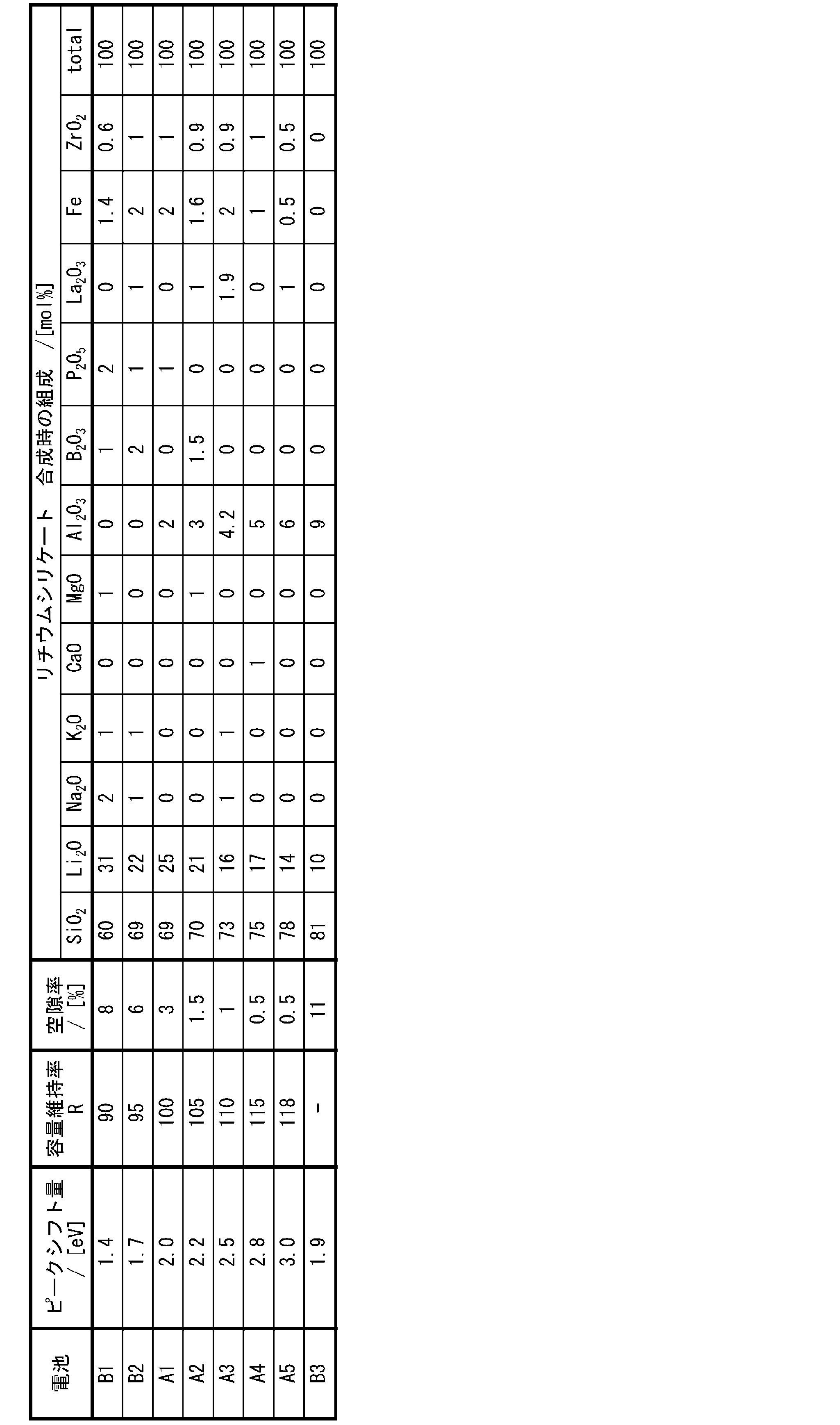
- Table 1 shows the evaluation results for each of the secondary batteries A1 to A5 and B1 to B3.
- Table 1 shows the evaluation results of the porosity, peak shift, and capacity retention rate R of the silicate composite particles used as the negative electrode active material of each battery.
- the capacity retention rate R is shown as a relative value with the capacity retention rate of Battery A1 set to 100.
- Table 1 shows the composition of the silicate phase of the silicate composite particles used as the negative electrode active material of each battery in the form of the mixing ratio (molar ratio) of the Li raw material, the Si raw material, and the compound of the element M used at the time of synthesis. , are shown together.
- the peak shift amount in Table 1 indicates how much the ELNES peak at the interface between the silicate phase and the silicon particles is shifted to the low energy side with respect to the ELNES peak in the silicate phase. From Table 1, the secondary batteries A1 to A6 with peak shift amounts in the range of 2.0 eV to 3.0 eV had a higher capacity retention rate R than the batteries B1 to B3.
- the amount of SiO 2 added was about the same as that of the battery B2
- the addition of Al 2 O 3 reduced the porosity and improved the capacity retention ratio R.
- the peak shift amount could be controlled within the range of 2.0 eV to 3.0 eV.
- Batteries A1 to A5 in which the SiO 2 addition amount is in the range of 69 mol % to 78 mol % and the Li 2 O addition amount is in the range of 14 mol % to 25 mol % have peak shift amounts of 2.0 eV to 3.0 eV. It was in the range of 0 eV, and in this case, the porosity was greatly reduced, and the capacity retention rate was remarkably improved.
- the present invention can provide a non-aqueous electrolyte secondary battery having high capacity and good charge-discharge cycle characteristics.
- the nonaqueous electrolyte secondary battery of the present invention is useful as a main power source for mobile communication devices, portable electronic devices, and the like. While the invention has been described in terms of presently preferred embodiments, such disclosure is not to be construed in a limiting sense. Various alterations and modifications will no doubt become apparent to those skilled in the art to which the invention pertains after reading the above disclosure. Therefore, the appended claims are to be interpreted as covering all variations and modifications without departing from the true spirit and scope of the invention.
Landscapes
- Chemical & Material Sciences (AREA)
- Chemical Kinetics & Catalysis (AREA)
- Electrochemistry (AREA)
- General Chemical & Material Sciences (AREA)
- Inorganic Chemistry (AREA)
- Organic Chemistry (AREA)
- Engineering & Computer Science (AREA)
- Materials Engineering (AREA)
- Manufacturing & Machinery (AREA)
- Crystallography & Structural Chemistry (AREA)
- Composite Materials (AREA)
- Battery Electrode And Active Subsutance (AREA)
Abstract
Description
本発明の新規な特徴を添付の請求の範囲に記述するが、本発明は、構成および内容の両方に関し、本発明の他の目的および特徴と併せ、図面を照合した以下の詳細な説明によりさらによく理解されるであろう。
<TEM-ELNES測定条件>
分析装置:JEOL製 JEM-F200
EELS検出器 Quantum ER(Gatan社製:JEM-F200に付属)
条件:加速電圧200kV
真空度:1×10⁻⁶~8.0×10⁻⁵Pa
dispersion:0.050eV/ch
probe diameter:0.16nm
probe current:0.05nA
カメラ長:40mm
pixel time:約0.1(s)
(1)日立ハイテク社製のイオンミリング装置(ex.IM4000)を用いて、母粒子の断面を露出させる。
(2)露出させた粒子断面をSEMで観察して、粒子断面の総面積に対する空隙の面積の割合を測定し、空隙率(空隙の面積×100/粒子断面の総面積)を算出する。空隙率は、粒子10個についての平均値とする。
負極合剤層の反射電子像の断面画像から、粒子の最大径が5μm以上のシリケート複合粒子を無作為に10個選び出して、それぞれについてエネルギー分散型X線(EDX)による元素のマッピング分析を行う。画像解析ソフトを用いて対象となる元素の面積割合を算出する。観察倍率は2000~20000倍が望ましい。粒子10個に含まれる所定の元素の面積割合の測定値を平均する。得られた平均値から対象となる元素の含有量が算出される。
<SEM-EDX測定条件>
加工装置:JEOL製、SM-09010(Cross Section Polisher)
加工条件:加速電圧6kV
電流値:140μA
真空度:1×10⁻³~2×10⁻³Pa
測定装置:電子顕微鏡HITACHI製SU-70
分析時加速電圧:10kV
フィールド:フリーモード
プローブ電流モード:Medium
プローブ電流範囲:High
アノード Ap.:3
OBJ Ap.:2
分析エリア:1μm四方
分析ソフト:EDAX Genesis
CPS:20500
Lsec:50
時定数:3.2
測定では、負極合剤層の反射電子像の断面画像から、粒子の最大径が5μm以上のシリケート複合粒子を無作為に10個選び出して、それぞれについてオージェ電子分光(AES)分析装置(例えば日本電子社製、JAMP-9510F)を用いて元素の定性定量分析を行う。測定条件は、例えば、加速電圧10kV、ビーム電流10nA、分析領域20μmφとすればよい。粒子10個に含まれる所定の元素の含有量を平均して含有量が算出される。
シリケート複合粒子の試料を、加熱した酸溶液(フッ化水素酸、硝酸および硫酸の混酸)中で全溶解し、溶液残渣の炭素を濾過して除去する。その後、得られた濾液を誘導結合プラズマ発光分光分析法(ICP)で分析して、各元素のスペクトル強度を測定する。続いて、市販されている元素の標準溶液を用いて検量線を作成し、Si含有粒子に含まれる各元素の含有量を算出する。
<Si-NMR測定条件>
測定装置:バリアン社製、固体核磁気共鳴スペクトル測定装置(INOVA‐400)
プローブ:Varian 7mm CPMAS-2
MAS:4.2kHz
MAS速度:4kHz
パルス:DD(45°パルス+シグナル取込時間1Hデカップル)
繰り返し時間:1200sec~3000sec
観測幅:100kHz
観測中心:-100ppm付近
シグナル取込時間:0.05sec
積算回数:560
試料量:207.6mg
工程(i)(リチウムシリケートを得る工程)
リチウムシリケートの原料には、Siを含む原料と、Li原料とを所定の割合で含む原料混合物を用いる。原料混合物に、上述の元素Mを含ませてもよい。元素Mを含む原料として、Al原料(例えば既述のアルミニウム化合物)を原料化合物に含ませることが好ましい。上記原料を所定量混合した混合物を溶解し、融液を金属ロールに通してフレーク化してリチウムシリケートを作製する。その後フレーク化したシリケートを大気雰囲気で、ガラス転移点以上、融点以下の温度で熱処理により結晶化させる。なおフレーク化したシリケートは結晶化させずに使用することも可能である。また所定量混合した混合物を例えば850℃以上融点以下の温度で溶解させずに焼成し、固相反応によりシリケートを製造することも可能である。
リチウムシリケート内には、Li原料と反応しなかったSi原料が残存し得る。残存するSi原料は、酸化シリコンの微細結晶として、リチウムシリケート内に分散している。
次に、リチウムシリケートに原料シリコンを配合して複合化が行われる。例えば、以下の工程(a)~(c)を経て、複合粒子が作製される。
まず、原料シリコンの粉末とリチウムシリケートの粉末とを、例えば、20:80~95:5の質量比で混合する。原料シリコンには、平均粒径が数μm~数十μm程度のシリコンの粗粒子を用いればよい。
次に、ボールミルのような粉砕装置を用いて、原料シリコンとリチウムシリケートの混合物を微粒子化しながら粉砕および複合化する。このとき、混合物に有機溶媒を添加して、湿式粉砕してもよい。所定量の有機溶媒を粉砕初期に一度に粉砕容器に投入してもよく、粉砕過程で所定量の有機溶媒を複数回に分けて間欠的に粉砕容器に投入してもよい。有機溶媒は、粉砕対象物の粉砕容器の内壁への付着を防ぐ役割を果たす。
次に、粉砕物を、ホットプレス等で圧力を印加しながら焼成して焼結体を得る。焼成は、例えば、不活性雰囲気(例えば、アルゴン、窒素等の雰囲気)中で行われる。焼成温度は、450℃以上、1000℃以下であることが好ましい。上記温度範囲である場合、結晶性が低いシリケート相内に微小なシリコン粒子を分散させやすい。焼結時に、リチウムシリケートが軟化し、シリコン粒子間の隙間を埋めるように流動する。その結果、シリケート相を海部とし、シリコン粒子を島部とする緻密なブロック状の焼結体を得ることができる。焼成温度は、好ましくは550℃以上、900℃以下であり、より好ましくは650℃以上、850℃以下である。焼成時間は、例えば、1時間以上、10時間以下である。
次に、シリケート複合粒子の表面の少なくとも一部を、導電性材料で被覆して導電層を形成してもよい。導電性材料は、電気化学的に安定であることが好ましく、導電性炭素材料が好ましい。導電性炭素材料としては、例えば、石炭ピッチもしくはコールタールピッチ、石油ピッチ、フェノール樹脂等を用い得る。導電性材料の原料と複合粒子とを混合し、混合物を焼成して導電性材料の原料を炭化させることで、複合粒子の表面の少なくとも一部を覆う導電層が形成される。
複合粒子(表面に導電層を有する場合を含む。)を酸で洗浄する工程を行ってもよい。例えば、酸性水溶液で複合粒子を洗浄することで、原料シリコンとリチウムシリケートとを複合化させる際に生じ得る、複合粒子の表面に存在する微量のアルカリ成分を溶解させ、除去することができる。酸性水溶液としては、塩酸、フッ化水素酸、硫酸、硝酸、リン酸、炭酸などの無機酸の水溶液や、クエン酸、酢酸などの有機酸の水溶液を用いることができる。
母粒子23は、リチウムシリケート相21と、シリケート相21内に分散しているシリコン粒子22と、を備える。母粒子23は、リチウムシリケート相21のマトリックス中に微細なシリコン粒子が分散した海島構造を有する。母粒子23の表面は、導電層26で被覆され、シリケート複合粒子20が形成される。
負極は、例えば、負極集電体と、負極集電体の表面に形成され、かつ負極活物質を含む負極合剤層とを具備する。負極合剤層は、負極合剤を分散媒に分散させた負極スラリーを、負極集電体の表面に塗布し、乾燥させることにより形成できる。乾燥後の塗膜を、必要により圧延してもよい。負極合剤層は、負極集電体の一方の表面に形成してもよく、両方の表面に形成してもよい。
正極は、例えば、正極集電体と、正極集電体の表面に形成された正極合剤層とを具備する。正極合剤層は、正極合剤を分散媒に分散させた正極スラリーを、正極集電体の表面に塗布し、乾燥させることにより形成できる。乾燥後の塗膜を、必要により圧延してもよい。正極合剤層は、正極集電体の一方の表面に形成してもよく、両方の表面に形成してもよい。
電解質は、溶媒と、溶媒に溶解したリチウム塩を含む。電解質におけるリチウム塩の濃度は、例えば、0.5~2mol/Lである。電解質は、公知の添加剤を含有してもよい。
通常、正極と負極との間には、セパレータを介在させることが望ましい。セパレータは、イオン透過度が高く、適度な機械的強度および絶縁性を備えている。セパレータとしては、微多孔薄膜、織布、不織布などを用いることができる。セパレータの材質としては、例えば、ポリプロピレン、ポリエチレンなどのポリオレフィンが用いられ得る。
[シリケート複合粒子の調製]
Li原料として炭酸リチウム(Li2CO3)と、Si原料として二酸化ケイ素(SiO2)と、元素Mの化合物とを、表1に示すモル比で混合し、混合物を不活性ガス雰囲気中で800℃で10時間焼成し、リチウムシリケートを得た。得られたリチウムシリケートは平均粒径10μmになるように粉砕した。表1において、リチウムおよび元素Mのモル比は、それぞれ、酸化物に換算したときのモル比を表す(ただし、Feは除く)。
シリケート複合粒子と黒鉛とを5:95の質量比で混合し、負極活物質として用いた。負極活物質と、カルボキシメチルセルロースナトリウム(CMC-Na)と、スチレン-ブタジエンゴム(SBR)とを、97.5:1:1.5の質量比で含む負極合剤に水を添加して攪拌し、負極スラリーを調製した。次に、銅箔の表面に1m2当りの負極合剤の質量が190gとなるように負極スラリーを塗布し、塗膜を乾燥後、圧延して、銅箔の両面に密度1.5g/cm3の負極合剤層が形成された負極を作製した。
LiNi0.88Co0.09Al0.03O2と、アセチレンブラックと、ポリフッ化ビニリデン(PVDF)とを、95:2.5:2.5の質量比で含む正極合剤にN-メチル-2-ピロリドン(NMP)を添加して攪拌し、正極スラリーを調製した。次に、アルミニウム箔の表面に正極スラリーを塗布し、塗膜を乾燥させた後、圧延して、アルミニウム箔の両面に、密度3.6g/cm3の正極合剤層が形成された正極を作製した。
エチレンカーボネート(EC)とジエチルカーボネート(DEC)とを3:7の体積比で含む混合溶媒にLiPF6を1.0mol/L濃度で溶解して非水電解液を調製した。
各電極にタブをそれぞれ取り付け、タブが最外周部に位置するように、セパレータを介して正極および負極を渦巻き状に巻回することにより電極群を作製した。電極群をアルミニウムラミネートフィルム製の外装体内に挿入し、105℃で2時間真空乾燥した後、非水電解液を注入し、外装体の開口部を封止して、二次電池を得た。
既述の方法により、負極合剤層の断面に対して酸素K端ELNES測定を行った。断面画像におけるシリケート相とシリコン粒子との界面にある位置、および、シリケート相内の位置をそれぞれ1箇所選択し、シリケート相とシリコン粒子との界面におけるELNESのピーク、および、シリケート相におけるELNESのピークから、ピークシフト量を求めた。
既述の方法により、シリケート複合粒子の空隙率(%)を求めた。
各電池について、下記条件で充放電を繰り返し行った。
<充電>
25℃で、1It(800mA)の電流で電圧が4.2Vになるまで定電流充電を行い、その後、4.2Vの電圧で電流が1/20It(40mA)になるまで定電圧充電した。
25℃で、1It(800mA)の電流で電圧が2.75Vになるまで定電流放電を行った。
本発明を現時点での好ましい実施態様に関して説明したが、そのような開示を限定的に解釈してはならない。種々の変形および改変は、上記開示を読むことによって本発明に属する技術分野における当業者には間違いなく明らかになるであろう。したがって、添付の請求の範囲は、本発明の真の精神および範囲から逸脱することなく、すべての変形および改変を包含する、と解釈されるべきものである。
Claims (7)
- シリケート相と、前記シリケート相に分散しているシリコン粒子と、を含むシリケート複合粒子を備え、
前記シリケート相と前記シリコン粒子との界面における酸素K端エネルギー損失吸収端微細構造のピークが、前記シリケート相における前記酸素K端エネルギー損失吸収端微細構造のピークに対して2.0eV~3.0eV、低エネルギー側にシフトしている、二次電池用負極活物質。 - 前記シリケート複合粒子の空隙率が6%未満である、請求項1に記載の二次電池用負極活物質。
- 前記シリケート複合粒子において、前記シリケート相は、酸化シリコン(SiO2)を69~78モル%の範囲で含有し、酸化リチウム(Li2O)を14~25モル%の範囲で含有し、酸化アルミニウム(Al2O3)を2~6モル%の範囲で含有する、請求項1または2に記載の二次電池用負極活物質。
- 前記シリケート相は、Li2SiO3、Li2Si2O5、およびSiO2からなる群より選択される少なくとも1種の結晶相を有する、請求項1~3のいずれか1項に記載の二次電池用負極活物質。
- 前記シリケート相は、Cu-Kα線を用いたX線回折法による回折パターンにおいて、
2θ=19.0°、2θ=23.7°、2θ=24.5°、および2θ=24.8°からなる群より選択される少なくとも1つの付近に、リチウムシリケートに由来するピークを有し、
2θ=20.4°、2θ=26.0°、および2θ=49.2°からなる群より選択される少なくとも1つの付近に、酸化シリコンに由来するピークを有する、請求項4に記載の二次電池用負極活物質。 - 前記シリケート相は、元素Mをさらに含み、
前記元素Mは、Na、K、Ca、Mg、Zr、Fe、B、Al、PおよびLaからなる群より選択される少なくとも1種である、請求項1~5のいずれか1項に記載の二次電池用負極活物質。 - 正極、負極、電解質および前記正極と前記負極との間に介在するセパレータを備え、
前記負極が、集電体と、負極活物質層と、を含み、
前記負極活物質層が、請求項1~6のいずれか1項に記載の二次電池用負極活物質を含む、二次電池。
Priority Applications (4)
| Application Number | Priority Date | Filing Date | Title |
|---|---|---|---|
| JP2023548491A JPWO2023042864A1 (ja) | 2021-09-17 | 2022-09-14 | |
| CN202280062334.4A CN117981113A (zh) | 2021-09-17 | 2022-09-14 | 二次电池用负极活性物质和二次电池 |
| US18/690,536 US20240413327A1 (en) | 2021-09-17 | 2022-09-14 | Negative electrode active material for secondary batteries, and secondary battery |
| EP22870011.8A EP4404301A4 (en) | 2021-09-17 | 2022-09-14 | Negative electrode active material for secondary batteries and secondary batteries |
Applications Claiming Priority (2)
| Application Number | Priority Date | Filing Date | Title |
|---|---|---|---|
| JP2021152568 | 2021-09-17 | ||
| JP2021-152568 | 2021-09-17 |
Publications (1)
| Publication Number | Publication Date |
|---|---|
| WO2023042864A1 true WO2023042864A1 (ja) | 2023-03-23 |
Family
ID=85602943
Family Applications (1)
| Application Number | Title | Priority Date | Filing Date |
|---|---|---|---|
| PCT/JP2022/034462 Ceased WO2023042864A1 (ja) | 2021-09-17 | 2022-09-14 | 二次電池用負極活物質および二次電池 |
Country Status (5)
| Country | Link |
|---|---|
| US (1) | US20240413327A1 (ja) |
| EP (1) | EP4404301A4 (ja) |
| JP (1) | JPWO2023042864A1 (ja) |
| CN (1) | CN117981113A (ja) |
| WO (1) | WO2023042864A1 (ja) |
Cited By (2)
| Publication number | Priority date | Publication date | Assignee | Title |
|---|---|---|---|---|
| EP4583208A4 (en) * | 2023-02-28 | 2026-03-04 | Contemporary Amperex Technology Hong Kong Ltd | Negative electrodeactivatable material based on silicon, secondary battery and electrical device |
| WO2026079470A1 (ja) * | 2024-10-10 | 2026-04-16 | パナソニックエナジー株式会社 | 負極活物質および二次電池 |
Citations (5)
| Publication number | Priority date | Publication date | Assignee | Title |
|---|---|---|---|---|
| JP2015153520A (ja) | 2014-02-12 | 2015-08-24 | 株式会社大阪チタニウムテクノロジーズ | リチウムイオン二次電池の負極用粉末、およびその製造方法 |
| JP2017091978A (ja) * | 2015-11-17 | 2017-05-25 | 信越化学工業株式会社 | 負極活物質、混合負極活物質材料、非水電解質二次電池用負極、リチウムイオン二次電池、及び負極活物質の製造方法 |
| JP2018152250A (ja) * | 2017-03-13 | 2018-09-27 | 信越化学工業株式会社 | 負極材及びその負極材の製造方法、並びに混合負極材 |
| WO2019130787A1 (ja) * | 2017-12-28 | 2019-07-04 | パナソニックIpマネジメント株式会社 | 非水電解質二次電池用負極活物質 |
| US20210111395A1 (en) * | 2018-01-31 | 2021-04-15 | Lg Chem, Ltd. | Negative electrode active material, negative electrode including the same and lithium secondary battery including the same |
Family Cites Families (1)
| Publication number | Priority date | Publication date | Assignee | Title |
|---|---|---|---|---|
| EP4098614A4 (en) * | 2020-01-31 | 2023-11-01 | Panasonic Intellectual Property Management Co., Ltd. | NEGATIVE ELECTRODE ACTIVE SUBSTANCE FOR SECONDARY BATTERY, METHOD FOR PRODUCING SAME AND SECONDARY BATTERY |
-
2022
- 2022-09-14 WO PCT/JP2022/034462 patent/WO2023042864A1/ja not_active Ceased
- 2022-09-14 EP EP22870011.8A patent/EP4404301A4/en active Pending
- 2022-09-14 CN CN202280062334.4A patent/CN117981113A/zh active Pending
- 2022-09-14 US US18/690,536 patent/US20240413327A1/en active Pending
- 2022-09-14 JP JP2023548491A patent/JPWO2023042864A1/ja active Pending
Patent Citations (5)
| Publication number | Priority date | Publication date | Assignee | Title |
|---|---|---|---|---|
| JP2015153520A (ja) | 2014-02-12 | 2015-08-24 | 株式会社大阪チタニウムテクノロジーズ | リチウムイオン二次電池の負極用粉末、およびその製造方法 |
| JP2017091978A (ja) * | 2015-11-17 | 2017-05-25 | 信越化学工業株式会社 | 負極活物質、混合負極活物質材料、非水電解質二次電池用負極、リチウムイオン二次電池、及び負極活物質の製造方法 |
| JP2018152250A (ja) * | 2017-03-13 | 2018-09-27 | 信越化学工業株式会社 | 負極材及びその負極材の製造方法、並びに混合負極材 |
| WO2019130787A1 (ja) * | 2017-12-28 | 2019-07-04 | パナソニックIpマネジメント株式会社 | 非水電解質二次電池用負極活物質 |
| US20210111395A1 (en) * | 2018-01-31 | 2021-04-15 | Lg Chem, Ltd. | Negative electrode active material, negative electrode including the same and lithium secondary battery including the same |
Non-Patent Citations (1)
| Title |
|---|
| See also references of EP4404301A4 |
Cited By (2)
| Publication number | Priority date | Publication date | Assignee | Title |
|---|---|---|---|---|
| EP4583208A4 (en) * | 2023-02-28 | 2026-03-04 | Contemporary Amperex Technology Hong Kong Ltd | Negative electrodeactivatable material based on silicon, secondary battery and electrical device |
| WO2026079470A1 (ja) * | 2024-10-10 | 2026-04-16 | パナソニックエナジー株式会社 | 負極活物質および二次電池 |
Also Published As
| Publication number | Publication date |
|---|---|
| US20240413327A1 (en) | 2024-12-12 |
| EP4404301A1 (en) | 2024-07-24 |
| EP4404301A4 (en) | 2025-04-30 |
| JPWO2023042864A1 (ja) | 2023-03-23 |
| CN117981113A (zh) | 2024-05-03 |
Similar Documents
| Publication | Publication Date | Title |
|---|---|---|
| JP7209266B2 (ja) | 非水電解質二次電池用負極活物質 | |
| JP7478973B2 (ja) | 二次電池用負極活物質および二次電池 | |
| JP7710186B2 (ja) | 二次電池 | |
| JP7620831B2 (ja) | 非水電解質二次電池用負極材料および非水電解質二次電池 | |
| US20240396019A1 (en) | Secondary battery | |
| US20240405201A1 (en) | Secondary battery | |
| JP7417903B2 (ja) | 二次電池用負極活物質および二次電池 | |
| JP7664538B2 (ja) | 二次電池用負極活物質およびこれを用いた二次電池 | |
| JP7660301B2 (ja) | 二次電池用負極活物質および二次電池 | |
| US20250201831A1 (en) | Negative electrode active material for secondary batteries, and secondary battery | |
| US20240413327A1 (en) | Negative electrode active material for secondary batteries, and secondary battery | |
| US20240396023A1 (en) | Negative electrode active substance for secondary battery, method for producing same, and secondary battery | |
| JP7336690B2 (ja) | 二次電池用負極活物質および二次電池 | |
| WO2024070707A1 (ja) | 二次電池用負極材料および二次電池 | |
| JP7681839B2 (ja) | 二次電池用負極活物質および二次電池 | |
| WO2024071116A1 (ja) | 二次電池用負極活物質、二次電池、および二次電池用負極活物質の製造方法 | |
| JP7738265B2 (ja) | 二次電池用負極活物質および二次電池 | |
| WO2024004520A1 (ja) | 二次電池用負極材料、および、二次電池 | |
| WO2023190241A1 (ja) | 二次電池用負極材料および二次電池 | |
| JP7417902B2 (ja) | 二次電池用負極活物質および二次電池 | |
| JP7788645B2 (ja) | 二次電池用負極活物質およびこれを用いた二次電池 | |
| US20250259995A1 (en) | Negative electrode active material for secondary batteries, and secondary battery | |
| WO2023008098A1 (ja) | 二次電池用負極活物質および二次電池 | |
| WO2025070505A1 (ja) | 二次電池用負極活物質、および二次電池 |
Legal Events
| Date | Code | Title | Description |
|---|---|---|---|
| 121 | Ep: the epo has been informed by wipo that ep was designated in this application |
Ref document number: 22870011 Country of ref document: EP Kind code of ref document: A1 |
|
| WWE | Wipo information: entry into national phase |
Ref document number: 2023548491 Country of ref document: JP |
|
| WWE | Wipo information: entry into national phase |
Ref document number: 18690536 Country of ref document: US |
|
| WWE | Wipo information: entry into national phase |
Ref document number: 202280062334.4 Country of ref document: CN |
|
| WWE | Wipo information: entry into national phase |
Ref document number: 2022870011 Country of ref document: EP |
|
| NENP | Non-entry into the national phase |
Ref country code: DE |
|
| ENP | Entry into the national phase |
Ref document number: 2022870011 Country of ref document: EP Effective date: 20240417 |