WO2023047771A1 - 立体物の製造方法 - Google Patents
立体物の製造方法 Download PDFInfo
- Publication number
- WO2023047771A1 WO2023047771A1 PCT/JP2022/027560 JP2022027560W WO2023047771A1 WO 2023047771 A1 WO2023047771 A1 WO 2023047771A1 JP 2022027560 W JP2022027560 W JP 2022027560W WO 2023047771 A1 WO2023047771 A1 WO 2023047771A1
- Authority
- WO
- WIPO (PCT)
- Prior art keywords
- print medium
- adhesive
- adhesive portion
- meth
- dimensional object
- Prior art date
- Legal status (The legal status is an assumption and is not a legal conclusion. Google has not performed a legal analysis and makes no representation as to the accuracy of the status listed.)
- Ceased
Links
Images












Classifications
-
- B—PERFORMING OPERATIONS; TRANSPORTING
- B32—LAYERED PRODUCTS
- B32B—LAYERED PRODUCTS, i.e. PRODUCTS BUILT-UP OF STRATA OF FLAT OR NON-FLAT, e.g. CELLULAR OR HONEYCOMB, FORM
- B32B37/00—Methods or apparatus for laminating, e.g. by curing or by ultrasonic bonding
- B32B37/12—Methods or apparatus for laminating, e.g. by curing or by ultrasonic bonding characterised by using adhesives
- B32B37/1284—Application of adhesive
- B32B37/1292—Application of adhesive selectively, e.g. in stripes, in patterns
-
- B—PERFORMING OPERATIONS; TRANSPORTING
- B42—BOOKBINDING; ALBUMS; FILES; SPECIAL PRINTED MATTER
- B42D—BOOKS; BOOK COVERS; LOOSE LEAVES; PRINTED MATTER CHARACTERISED BY IDENTIFICATION OR SECURITY FEATURES; PRINTED MATTER OF SPECIAL FORMAT OR STYLE NOT OTHERWISE PROVIDED FOR; DEVICES FOR USE THEREWITH AND NOT OTHERWISE PROVIDED FOR; MOVABLE-STRIP WRITING OR READING APPARATUS
- B42D15/00—Printed matter of special format or style not otherwise provided for
- B42D15/0073—Printed matter of special format or style not otherwise provided for characterised by shape or material of the sheets
-
- B—PERFORMING OPERATIONS; TRANSPORTING
- B32—LAYERED PRODUCTS
- B32B—LAYERED PRODUCTS, i.e. PRODUCTS BUILT-UP OF STRATA OF FLAT OR NON-FLAT, e.g. CELLULAR OR HONEYCOMB, FORM
- B32B37/00—Methods or apparatus for laminating, e.g. by curing or by ultrasonic bonding
- B32B37/12—Methods or apparatus for laminating, e.g. by curing or by ultrasonic bonding characterised by using adhesives
-
- B—PERFORMING OPERATIONS; TRANSPORTING
- B32—LAYERED PRODUCTS
- B32B—LAYERED PRODUCTS, i.e. PRODUCTS BUILT-UP OF STRATA OF FLAT OR NON-FLAT, e.g. CELLULAR OR HONEYCOMB, FORM
- B32B38/00—Ancillary operations in connection with laminating processes
- B32B38/0012—Mechanical treatment, e.g. roughening, deforming, stretching
-
- B—PERFORMING OPERATIONS; TRANSPORTING
- B42—BOOKBINDING; ALBUMS; FILES; SPECIAL PRINTED MATTER
- B42D—BOOKS; BOOK COVERS; LOOSE LEAVES; PRINTED MATTER CHARACTERISED BY IDENTIFICATION OR SECURITY FEATURES; PRINTED MATTER OF SPECIAL FORMAT OR STYLE NOT OTHERWISE PROVIDED FOR; DEVICES FOR USE THEREWITH AND NOT OTHERWISE PROVIDED FOR; MOVABLE-STRIP WRITING OR READING APPARATUS
- B42D15/00—Printed matter of special format or style not otherwise provided for
- B42D15/02—Postcards; Greeting, menu, business or like cards; Letter cards or letter-sheets
- B42D15/04—Foldable or multi-part cards or sheets
- B42D15/042—Foldable cards or sheets
-
- G—PHYSICS
- G03—PHOTOGRAPHY; CINEMATOGRAPHY; ANALOGOUS TECHNIQUES USING WAVES OTHER THAN OPTICAL WAVES; ELECTROGRAPHY; HOLOGRAPHY
- G03G—ELECTROGRAPHY; ELECTROPHOTOGRAPHY; MAGNETOGRAPHY
- G03G15/00—Apparatus for electrographic processes using a charge pattern
- G03G15/65—Apparatus which relate to the handling of copy material
- G03G15/6582—Special processing for irreversibly adding or changing the sheet copy material characteristics or its appearance, e.g. stamping, annotation printing, punching
- G03G15/6585—Special processing for irreversibly adding or changing the sheet copy material characteristics or its appearance, e.g. stamping, annotation printing, punching by using non-standard toners, e.g. transparent toner, gloss adding devices
-
- G—PHYSICS
- G03—PHOTOGRAPHY; CINEMATOGRAPHY; ANALOGOUS TECHNIQUES USING WAVES OTHER THAN OPTICAL WAVES; ELECTROGRAPHY; HOLOGRAPHY
- G03G—ELECTROGRAPHY; ELECTROPHOTOGRAPHY; MAGNETOGRAPHY
- G03G9/00—Developers
- G03G9/08—Developers with toner particles
-
- G—PHYSICS
- G03—PHOTOGRAPHY; CINEMATOGRAPHY; ANALOGOUS TECHNIQUES USING WAVES OTHER THAN OPTICAL WAVES; ELECTROGRAPHY; HOLOGRAPHY
- G03G—ELECTROGRAPHY; ELECTROPHOTOGRAPHY; MAGNETOGRAPHY
- G03G9/00—Developers
- G03G9/08—Developers with toner particles
- G03G9/087—Binders for toner particles
-
- G—PHYSICS
- G03—PHOTOGRAPHY; CINEMATOGRAPHY; ANALOGOUS TECHNIQUES USING WAVES OTHER THAN OPTICAL WAVES; ELECTROGRAPHY; HOLOGRAPHY
- G03G—ELECTROGRAPHY; ELECTROPHOTOGRAPHY; MAGNETOGRAPHY
- G03G9/00—Developers
- G03G9/08—Developers with toner particles
- G03G9/087—Binders for toner particles
- G03G9/08702—Binders for toner particles comprising macromolecular compounds obtained by reactions only involving carbon-to-carbon unsaturated bonds
- G03G9/08706—Polymers of alkenyl-aromatic compounds
- G03G9/08708—Copolymers of styrene
- G03G9/08711—Copolymers of styrene with esters of acrylic or methacrylic acid
-
- G—PHYSICS
- G03—PHOTOGRAPHY; CINEMATOGRAPHY; ANALOGOUS TECHNIQUES USING WAVES OTHER THAN OPTICAL WAVES; ELECTROGRAPHY; HOLOGRAPHY
- G03G—ELECTROGRAPHY; ELECTROPHOTOGRAPHY; MAGNETOGRAPHY
- G03G9/00—Developers
- G03G9/08—Developers with toner particles
- G03G9/087—Binders for toner particles
- G03G9/08784—Macromolecular material not specially provided for in a single one of groups G03G9/08702 - G03G9/08775
- G03G9/08797—Macromolecular material not specially provided for in a single one of groups G03G9/08702 - G03G9/08775 characterised by their physical properties, e.g. viscosity, solubility, melting temperature, softening temperature, glass transition temperature
-
- B—PERFORMING OPERATIONS; TRANSPORTING
- B32—LAYERED PRODUCTS
- B32B—LAYERED PRODUCTS, i.e. PRODUCTS BUILT-UP OF STRATA OF FLAT OR NON-FLAT, e.g. CELLULAR OR HONEYCOMB, FORM
- B32B2451/00—Decorative or ornamental articles
-
- G—PHYSICS
- G03—PHOTOGRAPHY; CINEMATOGRAPHY; ANALOGOUS TECHNIQUES USING WAVES OTHER THAN OPTICAL WAVES; ELECTROGRAPHY; HOLOGRAPHY
- G03G—ELECTROGRAPHY; ELECTROPHOTOGRAPHY; MAGNETOGRAPHY
- G03G2215/00—Apparatus for electrophotographic processes
- G03G2215/00362—Apparatus for electrophotographic processes relating to the copy medium handling
- G03G2215/00789—Adding properties or qualities to the copy medium
- G03G2215/00877—Folding device
Definitions
- the present invention relates to a method for manufacturing three-dimensional objects.
- the method for manufacturing a pop-up paper product described in Patent Document 1 includes a two-folding step (S1) for folding one sheet of paper in two, and a free end of the upper half surface that is positioned on the top surface by the two-folding step. and a predetermined portion of a triangle formed by connecting a predetermined point on a central line formed in a direction orthogonal to the folding line passing through the center of the valley-folded folding line and the intersection of the central line and the free end
- At least one embodiment of the present invention suppresses variation in the shape of a three-dimensional portion caused by variation in the position of the adhesive portion, compared to the case where the adhesive portion is formed on a portion of the print medium using a spray or the like. .
- an adhesive portion is formed on a part of a sheet-like print medium by electrophotography using a pressurized phase transition resin toner that exhibits adhesiveness by undergoing a phase transition under pressure. and forming a three-dimensional part by bending a part of the print medium and adhering the part of the print medium on which the adhesive part is formed to another part of the print medium to form a three-dimensional part. is.
- an image may also be formed on a print medium in the step of forming the adhesive portion.
- the first adhesive portion and the second adhesive portion having weaker adhesive strength than the first adhesive portion and a bond may be formed on the print medium.
- the toner concentration of the first adhesive portion is made higher than the toner concentration of the second adhesive portion.
- the adhesive portion may be formed on the print medium.
- the adhesive part is printed so that the adhesive force changes from the first adhesive part to the second adhesive part. It may be formed on a medium.
- the adhesive portion in the method for manufacturing a three-dimensional object described in [7] and [6], in the step of forming the adhesive portion, the adhesive portion may be formed in different colors on the front surface of the print medium and the back surface of the print medium.
- a portion of the print medium is folded to press the print medium into a flat shape.
- the portion of the print medium on which the adhesive portion is formed may be adhered to another portion of the print medium.
- the pressurized phase change resin toner comprises a styrene resin containing styrene and other vinyl monomers as polymerization components, and at least two a (meth)acrylic acid ester-based resin containing a (meth)acrylic acid ester as a polymerization component, and a (meth)acrylic acid ester-based resin in which the mass ratio of the (meth)acrylic acid ester to the entire polymerization component is 90% by mass or more, and at least two It may have two glass transition temperatures, and the difference between the lowest glass transition temperature and the highest glass transition temperature may be 30° C. or more.
- the pressurized phase-change resin toner contains pressurized phase-change resin toner particles, and the pressurized phase-change resin toner particles contain the styrene-based resin. and an island phase containing the (meth)acrylic acid ester-based resin dispersed in the sea phase.
- the island phase may have an average diameter of 200 nm or more and 500 nm or less.
- the number of types of toner can be reduced compared to the case where different types of toner are used to create differences in adhesive force.
- defective products can be easily extracted in the middle of the process compared to the case where the colors of the bonded portions are the same on the front and back surfaces.
- the printing method in which the adhesive part is formed Compared to the case where the part of the printing medium on which the adhesive part is formed is adhered to the other part of the printing medium by pressing the uneven printing medium, the printing method in which the adhesive part is formed Portions of the media can be easily adhered to other portions of the print media.
- the pressurized phase-change resin toner is a pressurized phase-change resin toner containing a styrene-based resin and a (meth)acrylic acid ester-based resin, wherein the (meth)acrylic acid ester-based resin is (meth) )
- the adhesiveness of the adhesive portion is superior to the case of applying a pressurized phase transition resin toner which is a homopolymer of an acrylate ester.
- the adhesiveness of the adhesive portion is excellent compared to the case where the pressurized phase change resin toner particles contained in the pressurized phase change resin toner do not have a sea-island structure.
- the adhesiveness of the adhesive portion is excellent compared to the case where the average diameter of the island phase of the sea-island structure of the pressurized phase change resin toner particles is more than 500 nm.
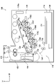
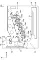
- FIG. 1 is a schematic configuration diagram showing an image forming apparatus used in a bonding portion forming step of a three-dimensional object manufacturing method according to the first exemplary embodiment of the present invention.
- FIG. 2 is a schematic configuration diagram showing a forming unit of an image forming apparatus used in a bonding portion forming step of a three-dimensional object manufacturing method according to the first exemplary embodiment of the present invention.
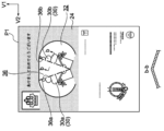
- FIG. 3A is a drawing showing an image formed on the surface of a print medium in a bonding portion forming process of a three-dimensional object manufacturing method according to the first exemplary embodiment of the present invention.
- FIG. 1 is a schematic configuration diagram showing an image forming apparatus used in a bonding portion forming step of a three-dimensional object manufacturing method according to the first exemplary embodiment of the present invention.
- FIG. 2 is a schematic configuration diagram showing a forming unit of an image forming apparatus used in a bonding portion forming step of a three-dimensional object manufacturing method according to the first exemplary embodiment of the present invention.
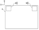
- FIG. 3B is a drawing showing an image formed on the back surface of the print medium in the bonding portion forming process of the three-dimensional object manufacturing method according to the first exemplary embodiment of the present invention.
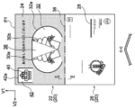
- FIG. 4A is a diagram illustrating a bonding portion formed on a surface of a print medium in a bonding portion forming process of a three-dimensional object manufacturing method according to the first exemplary embodiment of the present invention.
- FIG. 4B is a diagram illustrating a bonding portion formed on the back surface of the print medium in the bonding portion forming process of the three-dimensional object manufacturing method according to the first exemplary embodiment of the present invention.
- FIG. 5A is a process diagram showing a three-dimensional part forming process of the three-dimensional object manufacturing method according to the first exemplary embodiment of the present invention.
- FIG. 5B is a process diagram showing a three-dimensional part forming process of the three-dimensional object manufacturing method according to the first exemplary embodiment of the present invention.
- FIG. 6A is a process diagram showing a three-dimensional part forming process of the three-dimensional object manufacturing method according to the first exemplary embodiment of the present invention.
- FIG. 6B is a process diagram showing a three-dimensional part forming process of the three-dimensional object manufacturing method according to the first exemplary embodiment of the present invention.
- FIG. 7A is a process diagram showing a three-dimensional part forming process of the three-dimensional object manufacturing method according to the first exemplary embodiment of the present invention.
- FIG. 6A is a process diagram showing a three-dimensional part forming process of the three-dimensional object manufacturing method according to the first exemplary embodiment of the present invention.
- FIG. 7B is a process diagram showing a three-dimensional part forming process of the three-dimensional object manufacturing method according to the first exemplary embodiment of the present invention.
- FIG. 7C is a process diagram showing a three-dimensional part forming process of the three-dimensional object manufacturing method according to the first exemplary embodiment of the present invention.
- FIG. 8 is a process diagram showing a three-dimensional part forming process of the three-dimensional object manufacturing method according to the first exemplary embodiment of the present invention.
- FIG. 9A is a process diagram showing a bonding portion forming step and a three-dimensional portion forming step of a three-dimensional object manufacturing method according to the second exemplary embodiment of the present invention.
- FIG. 9B is a process diagram showing a bonding part forming process and a three-dimensional part forming process of the three-dimensional object manufacturing method according to the second exemplary embodiment of the present invention.
- FIG. 10A is a process diagram showing a three-dimensional part forming process of the three-dimensional object manufacturing method according to the second exemplary embodiment of the present invention.
- FIG. 10B is a process diagram showing a three-dimensional part forming process of the three-dimensional object manufacturing method according to the second exemplary embodiment of the present invention.
- FIG. 11A is a process diagram showing a bonding portion forming step and a three-dimensional portion forming step of a three-dimensional object manufacturing method according to the third exemplary embodiment of the present invention.
- FIG. 10A is a process diagram showing a three-dimensional part forming process of the three-dimensional object manufacturing method according to the second exemplary embodiment of the present invention.
- FIG. 11B is a process diagram showing a bonding portion forming step and a three-dimensional portion forming step of the three-dimensional object manufacturing method according to the third exemplary embodiment of the present invention.
- FIG. 12A is a process diagram showing a three-dimensional part forming process of a three-dimensional object manufacturing method according to the third exemplary embodiment of the present invention.
- FIG. 12B is a process diagram showing a three-dimensional part forming process of the three-dimensional object manufacturing method according to the third exemplary embodiment of the present invention.
- FIG. 13A is a process diagram showing a bonding portion forming step and a three-dimensional portion forming step of a three-dimensional object manufacturing method according to the fourth exemplary embodiment of the present invention.
- FIG. 12A is a process diagram showing a three-dimensional part forming process of a three-dimensional object manufacturing method according to the third exemplary embodiment of the present invention.
- FIG. 13B is a process diagram showing a bonding portion forming step and a three-dimensional portion forming step of a three-dimensional object manufacturing method according to the fourth exemplary embodiment of the present invention.
- FIG. 14A is a process diagram showing a three-dimensional part forming process of a three-dimensional object manufacturing method according to the fourth exemplary embodiment of the present invention.
- FIG. 14B is a process diagram showing a three-dimensional part forming process of the three-dimensional object manufacturing method according to the fourth exemplary embodiment of the present invention.
- FIG. 14C is a process diagram showing a three-dimensional part forming process of the three-dimensional object manufacturing method according to the fourth exemplary embodiment of the present invention.
- FIG. 14A is a process diagram showing a three-dimensional part forming process of a three-dimensional object manufacturing method according to the fourth exemplary embodiment of the present invention.
- FIG. 14B is a process diagram showing a three-dimensional part forming process of the three-dimensional object manufacturing method according to the fourth exemplary embodiment of the present
- FIG. 15 is a view showing the adhesive portion formed on the back surface of the print medium in the adhesive portion forming process of the three-dimensional object manufacturing method according to the fifth exemplary embodiment of the present invention.
- FIG. 16 is a schematic configuration diagram showing an image forming apparatus used in a three-dimensional object bonding portion forming process according to the sixth exemplary embodiment of the present invention.
- FIG. 17A is a drawing showing a bonding portion formed on the surface of a print medium in a bonding portion forming process of a three-dimensional object manufacturing method according to the sixth exemplary embodiment of the present invention.
- FIG. 17B is a drawing showing the adhesive portion formed on the back surface of the print medium in the adhesive portion forming process of the three-dimensional object manufacturing method according to the sixth exemplary embodiment of the present invention.
- FIG. 1 An example of a three-dimensional object manufacturing method according to the first exemplary embodiment of the present invention will be described with reference to FIGS. 1 to 8.
- FIG. 1 An example of a three-dimensional object manufacturing method according to the first exemplary embodiment of the present invention will be described with reference to FIGS. 1 to 8.
- FIG. 1 An example of a three-dimensional object manufacturing method according to the first exemplary embodiment of the present invention will be described with reference to FIGS. 1 to 8.
- a pressurized phase transition resin toner that exhibits adhesiveness by undergoing a phase transition under pressure is used to electrophotographically form an adhesive portion and an image on a portion of a sheet-like printing medium P1.
- a part forming step is provided.
- An “image” is an image formed for the purpose of being visually recognized by a user or an operator.
- the print medium P1 is a printable medium, such as plain paper, glossy paper, and coated paper.
- the print medium P1 is folded to bond the portion of the print medium P1 formed with the adhesive portion to another portion of the print medium P1, and at least a portion of the print medium P1 is attached to the other portion of the print medium P1.
- a three-dimensional portion forming step of forming a three-dimensional portion by folding is provided.
- the “other portion of the print medium P1” includes the other portion of the print medium P1 on which the adhesive portion is formed and the other portion of the print medium P1 on which the adhesive portion is not formed.
- the bonding portion forming step is a step of forming the bonding portion 50 and the image on the sheet-like print medium P1 by the electrophotographic image forming apparatus 100 using each toner. Specifically, in order to form the adhesive portion 50 , a pressurized phase-transition resin toner that exhibits adhesiveness by undergoing a phase transition under pressure is used, and in order to form the image 20 , each color toner is used.
- the image forming apparatus 100, the bonding portion 50 and the image 20 formed on the printing medium P1, and the process of forming the bonding portion 50 and the image 20 on the printing medium P1 using the image forming apparatus 100 will be described. do.
- FIG. 1 and 2 indicate the vertical direction of the device, and the arrow W indicates the width direction of the device (horizontal direction).
- a storage unit 114 that stores a sheet-shaped print medium P1
- a transport unit 116 that transports the print medium P1 stored in the storage unit 114
- a transport unit 116 that transports the print medium P1 from the storage unit 114.
- a forming unit 120 for forming the image 20 and the bonding unit 50 on the print medium P1.
- the storage unit 114, the transport unit 116, and the forming unit 120 are arranged in this order from the bottom to the top in the vertical direction of the apparatus.
- the storage unit 114 includes a storage member 126 that can be pulled out from the apparatus main body 100a of the image forming apparatus 100 toward the front side in the depth direction of the apparatus. Further, the storage member 126 includes a delivery roll 130 that delivers the print media P1 stacked on the storage member 126 to a transport path 128 that constitutes the transport section 116 .
- the transport unit 116 includes a plurality of transport rolls 132 that transport the print medium P1 along the transport path 128, and a discharge roll 176 that discharges the print medium P1 to the outside of the apparatus main body 100a.
- the transport unit 116 includes a double-sided transport unit 178 that reverses the front and back of the print medium P1 in order to form the adhesive part 50 and the image 20 on both sides of the print medium P1.
- the double-sided transport unit 178 includes a reversing path 182 through which the transported print medium P1 is fed by reversing the ejection rolls 176 .
- a plurality of transport rolls 184 are arranged along a reversing path 182, and the printing medium P1 transported by these transport rolls 184 is transported again to the transport rolls 132 in a state in which the front and back sides are reversed.
- the forming section 120 includes five forming units 118Y, 118M, 118C, 118K, and 118S for yellow (Y), magenta (M), cyan (C), black (K), and adhesion (S).
- Forming units 118Y, 118M, 118C, and 118K of yellow (Y), magenta (M), cyan (C), and black (K) use respective color toners to form images to be transferred to the print medium P1.
- the adhesive (S) forming unit 118S forms an adhesive portion that is transferred to the print medium P1 using a pressurized phase change resin toner.
- Each forming unit 118 has the same configuration except for the toner used.
- Each forming unit 118 includes, as shown in FIG. 2, an image carrier 136, a charging member 138 that charges the surface of the image carrier 136, an exposure device 142 that irradiates the image carrier 136 with exposure light, It has Further, each forming unit 118 includes a developing device 140 that develops an electrostatic latent image formed by irradiating the charged image carrier 136 with exposure light from an exposure device 142 and visualizes it as a toner image.
- the forming unit 120 includes an endless transfer belt 122 that rotates in the direction of arrow A in the drawing, a plurality of winding rolls 123 around which the transfer belt 122 is wound, and each forming unit 118. and a primary transfer roll 144 that transfers the toner image formed by the transfer belt 122 onto the transfer belt 122 . Further, the forming unit 120 heats and presses the secondary transfer roll 146 that transfers the toner image transferred to the transfer belt 122 to the printing medium P1, and the printing medium P1 onto which the toner image has been transferred, thereby transferring the toner image onto the printing medium. and a fixing device 150 for fixing to P1.
- the print medium P1 has a rectangular shape extending vertically in the figure.
- the image 20 formed on the surface of the print medium P1- is an image formed on one side (upper side in the figure) of the print medium P1 in the longitudinal direction of the print medium P1 (hereinafter referred to as the "medium longitudinal direction"). 22 and an image 26 formed on the other side (lower side in the drawing).
- the longitudinal direction of the medium is indicated by an arrow V1 in the drawing.
- the image 22 formed on one side in the longitudinal direction of the medium includes a colored portion 24 (portion indicated by dots in the drawing), a first pop-up image portion 30 formed inside the colored portion 24 and serving as a three-dimensional portion, a second pop-up image portion 40 formed inside the color portion 24 and serving as a three-dimensional portion;
- a "three-dimensional part” is a part that constitutes a part of a three-dimensional object manufactured from the printing medium P1 and that is raised with respect to other parts.
- a "three-dimensional portion” is a portion that is in a three-dimensional state rather than a planar state.
- this "three-dimensional part” there are two cases: when the three-dimensional object is manufactured, it is in a three-dimensional state, and when the three-dimensional object is manufactured, it is not in a three-dimensional state, but can be in a three-dimensional state. Including both.
- a blank portion 32 surrounded by the color portion 24 is located at the central portion in the longitudinal direction of the medium and also at the central portion in the transverse direction of the print medium P1 (hereinafter referred to as the "medium transverse direction"). to form The blank portion 32 has an oval shape extending in the lateral direction of the medium.
- a first pop-up image portion 30 is formed inside the blank portion 32 .
- the lateral direction of the medium is indicated by an arrow V2 in the figure.
- the first pop-up image portion 30 is divided in the short side direction of the medium into a first pop-up image portion 30a and a first pop-up image portion 30b. Between the first pop-up image portion 30a and the first pop-up image portion 30b, a triangular portion 36 which constitutes a part of the blank portion 32 and whose vertex faces the other side (lower side in the figure) in the longitudinal direction of the medium is provided. Form. The first popup image portion 30a and the first popup image portion 30b are in contact with each other at a point (point Z1 in the figure) on the other side in the medium longitudinal direction.
- a rectangular blank portion 42 surrounded by the colored portion 24 is formed on one side in the longitudinal direction of the medium and on one side in the lateral direction of the medium (left side in the drawing).
- a second pop-up image portion 40 is formed inside the blank portion 42 .
- the image 26 formed on the other side in the medium longitudinal direction includes a planar image portion 28 .
- the planar image portion 28 is formed on the other side (the right side in the drawing) of the print medium P1 in the short direction of the medium.
- the image 20 to be formed on the back surface of the print medium P1 includes a frame portion 44 and a frame portion 46, as shown in FIG. 3B.
- a frame portion 44 is formed at a portion on one side in the medium longitudinal direction and on one side in the medium transverse direction of the print medium P1, and at a portion on the other side in the medium longitudinal direction and in the medium transverse direction.
- a frame portion 46 is formed on one side portion.
- the frame portion 44 overlaps the edge portion of the blank portion 42 (see FIG. 3A) formed on the surface in the medium thickness direction.
- the frame portion 46 is symmetrical with the frame portion 44 with respect to the central portion in the longitudinal direction of the medium.
- the adhesive portion 50 (hereinafter referred to as "adhesive portion 50a") formed on the surface of the print medium P1 is a triangle with the vertex facing the other side in the longitudinal direction of the medium. Specifically, an adhesive portion 50a is formed in the triangular portion 36 shown in FIG. 3A.
- the adhesive portion 50a is colorless and transparent in this exemplary embodiment.
- the bonding portion 50a is an example of a first bonding portion.
- the adhesive portion 50 formed on the back surface of the print medium P1- includes an adhesive portion 50b and an adhesive portion 50c, as shown in FIG. 4B.
- the adhesive portions 50b, 50c are transparent and colorless in this exemplary embodiment.
- the bonding portion 50b is an example of a first bonding portion
- the bonding portion 50c is an example of a second bonding portion.
- a bonding portion 50b is formed in the portion other than the .
- the adhesive force of the adhesive portion 50b is equivalent to the adhesive force of the adhesive portion 50a shown in FIG. 4A.
- a rectangular adhesive portion 50c is formed inside the frame portion 46 shown in FIG. 3B.
- the adhesive force of the adhesive portion 50c is weaker than the adhesive force of the adhesive portions 50a and 50b. In other words, the adhesive force of the adhesive portions 50a and 50b is stronger than the adhesive force of the adhesive portion 50c.
- the strength of the adhesive force of the adhesive portion 50 can be changed by the toner concentration. Specifically, by making the toner density of the adhesive portions 50a and 50b higher than the toner density of the adhesive portion 50c, the adhesive strength of the adhesive portions 50a and 50b is increased compared to the adhesive strength of the adhesive portion 50c. Become stronger.
- the image forming apparatus 100 forms the adhesive portion 50 and the image 20 on the print medium P1 as follows.
- each charging member 138 (see FIG. 2) provided in each forming unit 118 and to which a voltage is applied uniformly negatively charges the surface of each image carrier 136 at a predetermined potential.
- each exposure device 142 irradiates the surface of each charged image carrier 136 with exposure light based on image data input from the outside to form an electrostatic latent image.
- each developing device 140 develops this electrostatic latent image into a toner image.
- the forming units 118Y, 118M, 118C, and 118K form a toner image corresponding to the image 20 to be formed on the surface of the printing medium P1
- the forming unit 118S forms an adhesive portion formed on the surface of the printing medium P1.
- a toner image corresponding to 50 is formed.
- the primary transfer roll 144 shown in FIG. 1 transfers the toner image formed on the surface of each image carrier 136 onto the transfer belt 122 .
- the print medium P1 delivered from the storage member 126 to the transport path 128 by the delivery roll 130 is delivered to the transfer position T where the transfer belt 122 and the secondary transfer roll 146 are in contact.
- the print medium P1 is conveyed between the transfer belt 122 and the secondary transfer roll 146, thereby transferring the toner image on the transfer belt 122 to the surface of the print medium P1.
- the image 20 to be formed on the surface of the print medium P1 and the toner image corresponding to the adhesive portion 50 are transferred to the surface of the print medium P1.
- the fixing device 150 fixes the toner image transferred to the surface of the print medium P1 onto the surface of the print medium P1.
- the printing medium P ⁇ b>1 with the toner image fixed on its surface is sent to the reversing path 182 .
- the print medium P ⁇ b>1 is turned upside down, and the transport rollers 184 transport the print medium P ⁇ b>1 to the transport rollers 132 .
- the forming units 118Y, 118M, 118C, and 118K form toner images corresponding to the image 20 formed on the back surface of the print medium P1 through the steps described above, and the forming unit 118S forms a toner image on the back surface of the print medium P1. A toner image corresponding to the adhesive portion 50 is formed.
- the print medium P1 is delivered to the transfer position T where the transfer belt 122 and the secondary transfer roll 146 are in contact. At the transfer position T, the print medium P1 is conveyed between the transfer belt 122 and the secondary transfer roll 146, thereby transferring the toner image on the transfer belt 122 to the back surface of the print medium P1. Specifically, the image 20 formed on the back surface of the print medium P1 and the toner image corresponding to the adhesive portion 50 are transferred to the back surface of the print medium P1.
- the fixing device 150 fixes the toner image transferred to the back surface of the print medium P1 to the back surface of the print medium P1.
- the discharge roll 176 that rotates forward discharges the print medium P1 on which the toner image is fixed to the outside of the apparatus main body 100a.
- the image forming apparatus 100 is used to form the image 20 and the adhesive portion 50 on the front and back surfaces of the printing medium P1.
- a notch 32a is formed in a part of the edge of the oval white portion 32 extending in the lateral direction of the medium, and the edge of the rectangular white portion 42 is cut.
- a notch 42a is formed in part.
- cuts 32a are formed in the linear edge on one side of the blank portion 32 in the medium longitudinal direction and on the curved edges on both sides of the blank portion 32 in the medium transverse direction.
- Incisions 42 a are formed at one linear edge in the medium longitudinal direction of the rectangular blank portion 42 and at both linear edges in the medium short direction of the blank portion 32 .
- the cuts 32a, 42a may be formed using, for example, a cutting machine.
- creases are formed at a boundary 36a between the triangular portion 36 and the first popup image portion 30a and at a boundary 36b between the triangular portion 36 and the first popup image portion 30b. do. Specifically, creases are formed at the boundaries 36a and 36b so as to form mountain folds when viewed from the surface side.
- the printing medium P1 is folded in two by folding the boundary 38 between the one side portion and the other side portion in the longitudinal direction of the printing medium P1. Specifically, the print medium P1 is folded in half by folding the boundary 38 so as to form a mountain fold when viewed from the front side.
- the boundary 39 between the one side portion and the other side portion of the folded print medium P1 in the short direction of the medium is folded, and the folded print medium P1 is folded. , then fold it in two again. Specifically, the boundary 39 is folded so as to form a valley fold when viewed from the front side, and the print medium P1 folded in half is further folded in half. By folding the printing medium P1 in four in this manner, the planar image portion 28 appears on the surface.
- the print medium P1 is folded in four to press the entire flat print medium P1 using a pair of rolls.
- the back surfaces of the printing medium P1 are bonded together by the bonding portion 50b shown in FIG. 4B, and the portion of the triangular portion 36 on one side and the other side in the medium width direction are bonded by the bonding portion 50a shown in FIG. 4A.
- the term “planar” refers to a state in which the print medium P1 does not have uneven portions.
- the formed blank portion 32 is raised against the color portion 24 .
- the first popup image portion 30 is an example of a stereoscopic portion.
- the blank portion 42 formed with the second pop-up image portion 40 that is a three-dimensional portion is raised with respect to the color portion 24 .
- the blank portion 42 is adhered to the back surface of the print medium P1 by the adhesive portion 50c shown in FIG. 4B.
- the adhesive force of the adhesive portion 50c is weaker than the adhesive force of the adhesive portion 50b. Therefore, the blank portion 42 formed with the second pop-up image portion 40 is peeled off from the back surface of the print medium P1 and raised against the color portion 24 .
- the second popup image portion 40 is an example of a stereoscopic portion.
- the three-dimensional object 110 having the three-dimensional portion formed thereon is manufactured using the printing medium P1.
- the image forming apparatus 100 forms the bonding portion 50 on a portion of the printing medium P1 using the pressurized phase change resin toner.
- variations in the shape of the three-dimensional portion due to variations in the position of the adhesive portion are suppressed compared to the case where the adhesive portion is formed on a portion of the print medium using a spray or the like.
- the image 20 is formed on the print medium P1 in the bonding portion forming step.
- the image forming apparatus 100 forms the adhesive portion 50 and the image 20 on the printing medium P1 in the adhesive portion forming step.
- variations in the relative positions of the adhesive portion 50 and the image 20 are suppressed compared to the case where the adhesive portion and the image are formed on the print medium in different steps.
- the adhesive force of the adhesive portions 50a and 50b is stronger than the adhesive force of the adhesive portion 50c. In this way, it is possible to deal with locations that require a strong adhesive force and locations that require a weak adhesive force.
- the toner concentration of the adhesive portions 50a and 50b is made higher than the toner concentration of the adhesive portion 50c, thereby creating a difference in adhesive force.
- the number of types of toner is reduced compared to the case where different types of toner are used to create different adhesive strengths.
- “Toner concentration” is the amount of toner per unit area of the print medium P1.
- the flat printing medium P1 is pressed to bond the back surfaces of the printing medium P1 to each other, and the triangular portion 36 on one side in the medium short direction is formed. and the part on the other side.
- the back surfaces of the print medium P1 can be easily adhered to each other, compared to the case where the portion of the print medium on which the adhesion portion is formed is adhered to another portion of the print medium by pressing the uneven print medium.
- the portion on one side and the portion on the other side of the triangular portion 36 in the transverse direction of the medium are easily adhered.
- FIGS. 9A, 9B, 10A and 10B An example of a three-dimensional object manufacturing method according to the second exemplary embodiment of the present invention will be described with reference to FIGS. 9A, 9B, 10A and 10B.
- the second exemplary embodiment will be mainly described for the parts that are different from the first exemplary embodiment.
- a three-dimensional object manufacturing method according to the second exemplary embodiment will be described separately for a bonding portion forming step and a three-dimensional portion forming step.
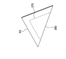
- the adhesive portion forming step As shown in FIG. 9A, the image 220 and the adhesive portion 250 are formed on the rectangular printing medium P2. Specifically, the adhesive portion 250 includes an adhesive portion 250a and an adhesive portion 250b.
- the bonding portion 250a is an example of a first bonding portion
- the bonding portion 250b is an example of a second bonding portion.
- the adhesive portion 250a is formed with a predetermined width along the outer edge of the print medium P2. In other words, the adhesive portion 250a is formed on the outer peripheral portion of the print medium P2. In the rectangular region surrounded by the bonding portion 250a, the bonding portion 250b is formed in a triangular region on one side with respect to the boundary 260 connecting the opposing corners.
- the adhesive force of the adhesive portion 250b is weaker than the adhesive force of the adhesive portion 250a. In other words, the adhesive force of the adhesive portion 250a is stronger than the adhesive force of the adhesive portion 250b.
- the image 220 which is a character image indicating "1 etc.”, is formed in the area on the opposite side of the adhesive part 250b across the boundary 260.
- perforations 270 are formed along part of the edge of the bonding portion 250b. Specifically, a perforation 270 is formed on the edge of the adhesive portion 250b facing the adhesive portion 250a. Perforations 270 may be formed using, for example, a perforation cutter.
- the print medium P2 is folded in half at the boundary 260 so that the image 220 is hidden. Furthermore, by pressing the entire print medium P2, the peripheral portions of the print medium P2 are adhered together by the adhesion portion 250a shown in FIG. 9A. Further, the portion of the print medium P2 on which the image 220 is formed is adhered to the adhesive portion 250b by the adhesive portion 250b shown in FIG. 9A.
- the perforation 270 cuts out and raises a region portion 272 surrounded by the perforation 270, which is a three-dimensional portion. This exposes the image 220 to the outside.
- Region portion 272 is an example of a three-dimensional portion.
- a three-dimensional object 210 having a three-dimensional portion is manufactured using the printing medium P2.
- ⁇ Third Exemplary Embodiment> An example of a three-dimensional object manufacturing method according to the third exemplary embodiment of the present invention will be described with reference to FIGS. 11A, 11B, 12A and 12B.
- the third exemplary embodiment will mainly be described for the parts that differ from the first exemplary embodiment.
- a three-dimensional object manufacturing method according to the third exemplary embodiment will be described separately for a bonding portion forming step and a three-dimensional portion forming step.
- a bonding portion 350 is formed on a portion of the front surface and a portion of the back surface of a rectangular print medium P3 extending in the horizontal direction in the drawing. .
- an adhesive portion 350 (hereinafter “adhesive portion 350a") is formed on the surface of the print medium P3, as shown in FIG. 11A. Specifically, the adhesive portion 350a is formed on one side of the print medium P3 in the longitudinal direction of the medium so as to extend in the lateral direction of the medium.
- an adhesive portion 350 (hereinafter “adhesive portion 350b") is formed on the back surface of the print medium P3, as shown in FIG. 11B.
- the adhesive portion 350b is formed on the other side of the print medium P3 in the medium longitudinal direction so as to extend in the medium lateral direction.
- the width of the adhesive portion 350b is the same as the width of the adhesive portion 350a.
- the portion of the printing medium P3 excluding the portion where the adhesive portion 350b is formed is divided equally into four in the longitudinal direction of the printing medium P3. A crease that becomes a mountain fold is formed.
- the print medium P3 is folded in half so that the adhesive portion 350a and the adhesive portion 350b overlap.
- the portion of the print medium P3 on which the adhesive portion 350a is formed and the portion of the print medium P3 on which the adhesive portion 350b is formed are adhered.
- the print medium P3 that has been folded in half is spread out so that there is a space inside, and the print medium P3 is shaped like a quadrangular prism.
- the three-dimensional object 310 is manufactured using the printing medium P3.
- a three-dimensional object 310 in the shape of a quadrangular prism is an example of a three-dimensional portion.
- FIGS. 13A, 13B, 14A, 14B, and 14C An example of a three-dimensional object manufacturing method according to the fourth exemplary embodiment of the present invention will be described with reference to FIGS. 13A, 13B, 14A, 14B, and 14C.
- the fourth exemplary embodiment will be mainly described for the parts that are different from the first exemplary embodiment.
- a three-dimensional object manufacturing method according to the fourth exemplary embodiment will be described separately for the bonding portion forming step and the three-dimensional portion forming step.
- the printing medium P4 and the printing medium P5 are used in the three-dimensional object manufacturing method according to the fourth exemplary embodiment.
- the print medium P4 has a rectangular shape extending in the horizontal direction in the drawing.
- the print medium P5 has a rectangular shape extending vertically in the drawing, and has a shape similar to that of the print medium P4 folded in half in the longitudinal direction of the medium.
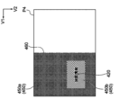
- Adhesion portion forming step In the adhesive portion forming step, as shown in FIG. 13A, an adhesive portion 450 and an image 420 are formed on the print medium P4.
- the adhesive portion 450 is formed on one side of the boundary 460 that divides the printing medium P4 into two in the longitudinal direction of the medium.
- the adhesive portion 450 includes an adhesive portion 450a and an adhesive portion 450b having a weaker adhesive force than the adhesive portion 450a.
- the bonding portion 450a is an example of a first bonding portion
- the bonding portion 450b is an example of a second bonding portion.
- a rectangular adhesive portion 450b extending in the longitudinal direction of the medium is formed on one side (lower side in the drawing) in the medium transverse direction.
- a bonding portion 450a is formed in a portion other than the bonding portion 40b so as to surround the bonding portion 450b.
- An image 420 which is a character image indicating "confidential information", is formed on the adhesive portion 450b.
- perforations 470 are formed on the print medium P5. Specifically, when the print medium P5 is laid over the portion of the print medium P4 where the adhesive portion 450 is formed, perforations are made in the portion of the print medium P5 that overlaps the left and right edges and the lower edge of the adhesive portion 450b. 470 is formed.
- the print medium P5 is placed on the portion of the print medium P4 where the adhesive portion 450 is formed.
- the print medium P4 is folded in half at the boundary 460 so that the perforations 470 are hidden. Furthermore, in this state, by pressing the entire print medium P4, the print medium P5 is adhered to the print medium P4 by the adhesion portion 450 shown in FIG. 13A.
- the printing medium P4 folded in half is opened, and an area portion 472 surrounded by the perforations 470, which is a three-dimensional portion, is cut and raised.
- Region portion 472 is an example of a three-dimensional portion.
- a three-dimensional object 410 having a three-dimensional portion is manufactured using the print media P4 and P5.
- an adhesive portion 550 is formed on the back surface of the print medium P1.
- the adhesive portion 550 includes an adhesive portion 550a, an adhesive portion 550b, an adhesive portion 550c, and an adhesive portion 50c.
- the bonding portion 550a is an example of a first bonding portion
- the bonding portion 550c is an example of a second bonding portion.
- an adhesive portion 550a extending in the lateral direction of the medium is formed in the central portion in the longitudinal direction of the medium. Further, a pair of adhesive portions 550b extending in the lateral direction of the medium are formed so as to sandwich the adhesive portion 550a from the longitudinal direction of the medium. Also, a pair of adhesive portions 550c extending in the lateral direction of the medium are formed so as to sandwich the pair of adhesive portions 550b from the longitudinal direction of the medium.
- the adhesive strength increases stepwise in the order of the adhesive portion 550c, the adhesive portion 550b, and the adhesive portion 550a. That is, the adhesive force of the adhesive portion 550a closest to the boundary 38 in the center in the longitudinal direction of the medium is stronger than those of the adhesive portions 550c and 550b, and the adhesive force of the adhesive portion 550c furthest from the boundary 38 is greater than that of the adhesive portions 550a and 550b. weaker than In other words, in the portion near the boundary 38 that is folded in the three-dimensional portion forming step, the adhesive force acting on the adhesive portion 550a is strong, and in the portion far from the boundary 38, the adhesive force acting on the adhesive portion 550c is weak. is weak.
- the bonding portion 550b sandwiched between the bonding portion 550a and the bonding portion 550c has a moderate bonding strength.
- the method of manufacturing a three-dimensional object corresponds to a place where a moderate adhesive strength between strong and weak adhesive strength is required.
- FIGS. 16, 17A, and 17B An example of a three-dimensional object manufacturing method according to the sixth exemplary embodiment of the present invention will be described with reference to FIGS. 16, 17A, and 17B.
- the sixth exemplary embodiment will mainly be described for the parts that are different from the first exemplary embodiment.
- the image forming apparatus 600 shown in FIG. 16 is used in the bonding portion forming process according to the sixth exemplary embodiment.
- the forming unit 120 of the image forming apparatus 600 includes six forming units 118Y for yellow (Y), magenta (M), cyan (C), black (K), first adhesion (S1), and second adhesion (S2). , 118M, 118C, 118K, 118S1, 118S2.
- the color of the adhesive portion 650 formed by the forming unit 118S1 is different from the color of the adhesive portion 650 formed by the forming unit 118S2.
- the bonded portion 650 formed by the forming unit 118S1 and the bonded portion 650 formed by the forming unit 118S2 can be visually distinguished.
- a triangular adhesive portion 650 (hereinafter “adhesive portion 650a”) is formed on the surface of the print medium P1, as shown in FIG. 17A.
- the bonding portion 650a is formed by the forming unit 118S1.
- a bonding portion 650 (hereinafter “bonding portion 650b”) and a bonding portion 650 (hereinafter “bonding portion 650c”) surrounded by the bonding portion 650b are formed. do.
- the bonding portions 650b and 650c are formed by the forming unit 118S2.
- the bonding portion 650a and the bonding portion 650b are examples of a first bonding portion
- the bonding portion 650c is an example of a second bonding portion.
- pressurized phase-change resin toner (hereinafter simply referred to as "pressurized phase-change resin toner") used in the bonding portion forming step in each exemplary embodiment will be described below.
- the pressurized phase change resin toner is a styrenic resin containing styrene and other vinyl monomers as polymerization components; At least two (meth)acrylic acid esters are included in the polymerization components, and the (meth)acrylic acid ester resin in which the mass ratio of the (meth)acrylic acid esters to the total polymerization components is 90% by mass or more, It preferably has at least two glass transition temperatures and the difference between the lowest and highest glass transition temperatures is 30° C. or more.
- the pressurized phase change resin toner exhibits a thermal property that "it has at least two glass transition temperatures, and the difference between the lowest glass transition temperature and the highest glass transition temperature is 30° C. or more.” It undergoes a phase transition under pressure.
- a pressurized phase-change resin toner that undergoes a phase transition under pressure means a pressurized phase-change resin toner that satisfies Formula 1 below.
- T1 is the temperature at which the viscosity is 10000 Pa ⁇ s under a pressure of 1 MPa
- T2 is the temperature at which the viscosity is 10000 Pa ⁇ s under a pressure of 10 MPa. How to obtain the temperature T1 and the temperature T2 will be described later.
- the pressurized phase change resin toner includes "a styrene resin containing styrene and other vinyl monomers as polymerization components” and "a styrene resin containing at least two kinds of (meth)acrylic acid esters as polymerization components and occupying the entire polymerization components (meth) ) a (meth)acrylic acid ester-based resin in which the mass ratio of the acrylic acid ester is 90% by mass or more.”
- a styrene resin containing at least two kinds of (meth)acrylic acid esters as polymerization components and occupying the entire polymerization components (meth) ) a (meth)acrylic acid ester-based resin in which the mass ratio of the acrylic acid ester is 90% by mass or more As a result, the adhesiveness of the bonded portion is enhanced.
- the mechanism is presumed to be as follows.
- both resins are included in the pressurized phase-change resin toner particles in a phase-separated state.
- the pressurized phase change resin toner particles are pressurized, the (meth)acrylic acid ester resin, which has a relatively low glass transition temperature, is first fluidized, and this fluidization spreads to the styrene resin, and both resins are fluidized.
- Both resins in the pressurized phase change resin toner particles are considered to form a phase-separated state again due to their low compatibility when they are fluidized by pressurization and then solidified by depressurization to form a resin layer.
- the (meth)acrylic acid ester resin containing at least two (meth)acrylic acid esters in the polymerization component has at least two types of ester groups bonded to the main chain, so that (meth)acrylic acid Compared to homopolymers of esters, the degree of molecular alignment in the solid state is low, so it is assumed that they are easily fluidized by pressurization.
- the pressurized phase change resin toner flows under pressure more than the pressurized phase change resin toner in which the (meth)acrylic acid ester-based resin is a homopolymer of (meth)acrylic acid ester. It is presumed that the phase transition is likely to occur due to pressure.
- a (meth)acrylic acid ester-based resin containing at least two (meth)acrylic acid esters in the polymerization component and having a mass ratio of the (meth)acrylic acid ester in the total polymerization component of 90% by mass or more is solidified again. Since the degree of alignment of the molecules is low even in the case, it is presumed that the phase separation with the styrenic resin becomes a minute phase separation. It is presumed that the finer the state of phase separation between the styrene-based resin and the (meth)acrylic acid ester-based resin, the higher the uniformity of the adhesive surface to the adherend and the better the adhesiveness.
- the pressurized phase change resin toner according to the present exemplary embodiment has better adhesiveness than the pressurized phase change resin toner in which the (meth)acrylic acid ester-based resin is a homopolymer of (meth)acrylic acid ester. presumed to be excellent.
- styrene-based resin means “styrene-based resin containing styrene and other vinyl monomers as polymerization components”
- (meth)acrylic acid ester-based resin means "at least two It means a (meth)acrylic acid ester-based resin that contains the seed (meth)acrylic acid ester as a polymerization component and that the (meth)acrylic acid ester accounts for 90% by mass or more of the total polymerization component.
- the pressurized phase change resin toner contains at least pressurized phase change resin toner particles and, if necessary, an external additive.
- the pressurized phase change resin toner particles contain at least a styrene-based resin and a (meth)acrylic acid ester-based resin.
- the pressurized phase change resin toner particles may contain colorants, release agents, and other additives.
- the pressurized phase change resin toner particles preferably have a higher content of styrene-based resin than the content of (meth)acrylic acid ester-based resin.
- the content of the styrene resin is preferably 55% by mass or more and 80% by mass or less, more preferably 60% by mass or more and 75% by mass or less, based on the total content of the styrene resin and the (meth)acrylic acid ester resin. , more preferably 65% by mass or more and 70% by mass or less.
- the pressurized phase change resin toner particles constituting the pressurized phase change resin toner contain a styrene-based resin containing styrene and other vinyl monomers as polymer components.
- the mass ratio of styrene to the total polymerized components of the styrene resin is preferably 60% by mass or more, more preferably 70% by mass or more. is more preferably 75% by mass or more, and from the viewpoint of forming a pressurized phase transition resin toner that easily undergoes phase transition under pressure, it is preferably 95% by mass or less, more preferably 90% by mass or less, and 85% by mass or less. More preferred.
- vinyl monomers other than styrene that constitute styrene resins include styrene monomers other than styrene and acrylic monomers.
- styrenic monomers other than styrene include alkyl-substituted styrene; aryl-substituted styrene; alkoxy-substituted styrene; halogen-substituted styrene; nitro-substituted styrene; Styrenic monomers may be used singly or in combination of two or more.
- the acrylic monomer is preferably at least one acrylic monomer selected from the group consisting of (meth)acrylic acid and (meth)acrylic acid ester.
- (meth)acrylic acid esters include (meth)acrylic acid alkyl esters, (meth)acrylic acid carboxy-substituted alkyl esters, (meth)acrylic acid hydroxy-substituted alkyl esters, (meth)acrylic acid alkoxy-substituted alkyl esters, di(meth)acrylic acid esters. ) acrylic acid esters and the like.
- One type of acrylic monomer may be used alone, or two or more types may be used in combination.
- vinyl monomers constituting styrene resins include, in addition to styrene monomers and acrylic monomers, for example, (meth)acrylonitrile; vinyl ethers; vinyl ketones; and olefins.
- the styrene-based resin preferably contains a (meth)acrylic acid ester as a polymerization component, more preferably a (meth)acrylic acid alkyl ester, from the viewpoint of forming a pressurized phase-transition resin toner that easily undergoes a phase transition under pressure. More preferably, it contains an alkyl (meth)acrylate having an alkyl group having 2 to 10 carbon atoms, and an alkyl (meth)acrylate having an alkyl group having 4 to 8 carbon atoms. More preferably, it contains an ester, particularly preferably at least one of n-butyl acrylate and 2-ethylhexyl acrylate.
- the styrene-based resin and the (meth)acrylic acid ester-based resin preferably contain the same (meth)acrylic acid ester as a polymerization component from the viewpoint of forming a pressurized phase-change resin toner that undergoes phase transition easily under pressure.
- the mass ratio of the (meth)acrylic acid ester to the total polymerized components of the styrene resin is preferably 40% by mass or less from the viewpoint of suppressing fluidization of the pressurized phase change resin toner in a non-pressurized state. , more preferably 30% by mass or less, more preferably 25% by mass or less, and from the viewpoint of forming a pressurized phase transition resin toner that easily undergoes phase transition under pressure, it is preferably 5% by mass or more, more preferably 10% by mass or more; 15% by mass or more is more preferable.
- an alkyl (meth)acrylic acid ester is preferable, and an alkyl (meth)acrylic acid ester having an alkyl group having 2 to 10 carbon atoms is more preferable.
- a (meth)acrylic acid alkyl ester having 4 or more and 8 or less carbon atoms is more preferable.
- the styrene resin contains at least one of n-butyl acrylate and 2-ethylhexyl acrylate as a polymerization component, and the total amount of n-butyl acrylate and 2-ethylhexyl acrylate in the total polymerization components of the styrene resin is The amount is preferably 40% by mass or less, more preferably 30% by mass or less, and even more preferably 25% by mass or less, from the viewpoint of suppressing fluidization of the pressurized phase change resin toner in a non-pressurized state. From the viewpoint of forming a pressurized phase transition resin toner that easily undergoes phase transition under pressure, the content is preferably 5% by mass or more, more preferably 10% by mass or more, and even more preferably 15% by mass or more.
- the weight-average molecular weight of the styrene-based resin is preferably 3000 or more, more preferably 4000 or more, and even more preferably 5000 or more, from the viewpoint of suppressing fluidization of the pressurized phase change resin toner in a non-pressurized state. It is preferably 60,000 or less, more preferably 55,000 or less, and even more preferably 50,000 or less, from the viewpoint of forming a pressurized phase transition resin toner that easily undergoes phase transition under pressure.
- the weight average molecular weight of the resin is measured by gel permeation chromatography (GPC). Molecular weight measurement by GPC is performed using Tosoh's HLC-8120GPC as a GPC apparatus, using Tosoh's TSKgel SuperHM-M (15 cm) as a column, and using tetrahydrofuran as a solvent. The weight average molecular weight of the resin is calculated using a molecular weight calibration curve prepared from monodisperse polystyrene standard samples.
- the glass transition temperature of the styrene resin is preferably 30° C. or higher, more preferably 40° C. or higher, from the viewpoint of suppressing fluidization of the pressurized phase change resin toner in a non-pressurized state.
- the temperature is preferably 50° C. or higher, more preferably 50° C. or higher.
- the temperature is preferably 110° C. or lower, more preferably 100° C. or lower, and 90° C. °C or less is more preferable.
- the glass transition temperature of the resin is obtained from a differential scanning calorimetry curve (DSC curve) obtained by performing differential scanning calorimetry (DSC). More specifically, it is determined according to the "extrapolated glass transition start temperature" described in the method for determining the glass transition temperature of JIS K7121:1987 "Method for measuring the transition temperature of plastics".
- the glass transition temperature of the resin can be controlled by the type and polymerization ratio of the polymer components.
- the glass transition temperature tends to be lower as the density of aliphatic groups in the side chains is higher.
- the mass ratio of the styrene-based resin to the entire pressurized phase change resin toner particles is preferably 55 mass% or more, and 60 mass%. More preferably 65% by mass or more, more preferably 80% by mass or less, more preferably 75% by mass or less, more preferably 70% by mass or less from the viewpoint of forming a pressurized phase transition resin toner that undergoes phase transition easily by pressure. % or less is more preferable.
- the pressurized phase change resin toner particles constituting the pressurized phase change resin toner contain at least two kinds of (meth)acrylic acid esters as polymerized components, and the mass ratio of the (meth)acrylic acid esters to the total polymerized components is 90. It contains a (meth)acrylic acid ester-based resin that is at least 10% by mass.
- the mass ratio of the (meth)acrylic acid ester to the total polymerization components of the (meth)acrylic acid ester resin is 90% by mass or more, more preferably 95% by mass or more, further preferably 98% by mass or more, and 100% by mass. % is more preferred.
- (meth)acrylic acid esters examples include (meth)acrylic acid alkyl esters, (meth)acrylic acid carboxy-substituted alkyl esters, (meth)acrylic acid hydroxy-substituted alkyl esters, (meth)acrylic acid alkoxy-substituted alkyl esters, di(meth)acrylic acid esters. ) acrylic acid esters and the like. (Meth)acrylic acid esters may be used alone or in combination of two or more.
- the (meth)acrylic acid ester is preferably an alkyl (meth)acrylic acid ester from the viewpoint of forming a pressurized phase-transition resin toner that easily undergoes phase transition under pressure and has excellent adhesiveness, and the alkyl group has two carbon atoms.
- a (meth)acrylic acid alkyl ester having at least 10 carbon atoms is more preferable, and a (meth)acrylic acid alkyl ester having an alkyl group having from 4 to 8 carbon atoms is more preferable, and n-butyl acrylate and acrylic acid 2-ethylhexyl is particularly preferred.
- the styrene-based resin and the (meth)acrylic acid ester-based resin preferably contain the same (meth)acrylic acid ester as a polymerization component from the viewpoint of forming a pressurized phase-change resin toner that undergoes phase transition easily under pressure.
- the mass ratio of the (meth)acrylic acid alkyl ester to the total polymerized components of the (meth)acrylic acid ester resin is 90 from the viewpoint of forming a pressurized phase transition resin toner that easily undergoes phase transition under pressure and has excellent adhesiveness. It is preferably at least 95% by mass, even more preferably at least 98% by mass, even more preferably at least 100% by mass.
- the (meth)acrylic acid alkyl ester used here is preferably a (meth)acrylic acid alkyl ester having an alkyl group having 2 or more and 10 or less carbon atoms, and an alkyl group having 4 or more and 8 or less carbon atoms. Certain (meth)acrylic acid alkyl esters are more preferred.
- the mass ratio of the two that have the highest mass ratio is an additive that is easy to undergo phase transition under pressure and has excellent adhesiveness.
- the ratio is preferably 80:20 to 20:80, more preferably 70:30 to 30:70, and further preferably 60:40 to 40:60. preferable.
- the two having the highest mass ratio are preferably (meth)acrylic acid alkyl esters.
- the (meth)acrylic acid alkyl ester used here is preferably a (meth)acrylic acid alkyl ester having an alkyl group having 2 or more and 10 or less carbon atoms, and an alkyl group having 4 or more and 8 or less carbon atoms. Certain (meth)acrylic acid alkyl esters are more preferred.
- the two (meth)acrylic acid esters contained as polymerization components in the (meth)acrylic acid ester-based resin are the (meth)acrylic acid alkyl esters with the highest mass ratio
- the two ( The difference in the number of carbon atoms in the alkyl group of the meth)acrylic acid alkyl ester is preferably 1 or more and 4 or less from the viewpoint of forming a pressurized phase transition resin toner that is easily transferred by pressure and has excellent adhesiveness. It is more preferably 2 or more and 4 or less, and still more preferably 3 or 4.
- the (meth)acrylic acid ester-based resin contains n-butyl acrylate and 2-ethylhexyl acrylate as polymerizable components from the viewpoint of forming a pressurized phase-change resin toner that easily undergoes phase transition under pressure and has excellent adhesiveness. is preferable, and among the at least two (meth)acrylic acid esters contained as polymerization components in the (meth)acrylic acid ester-based resin, the two having the highest mass ratio are n-butyl acrylate and 2-ethylhexyl acrylate.
- the total amount of n-butyl acrylate and 2-ethylhexyl acrylate in the total polymerization components of the (meth)acrylate resin is preferably 90% by mass or more, more preferably 95% by mass or more, and 98% by mass or more. More preferably, 100% by mass is even more preferable.
- the (meth)acrylic acid ester-based resin may contain a vinyl monomer other than the (meth)acrylic acid ester as a polymerization component.
- Vinyl monomers other than (meth)acrylic acid esters include, for example, (meth)acrylic acid; styrene; styrene-based monomers other than styrene; (meth)acrylonitrile; vinyl ethers such as vinyl methyl ether and vinyl isobutyl ether; vinyl ketones such as vinyl ethyl ketone and vinyl isopropenyl ketone; olefins such as isoprene, butene and butadiene; These vinyl monomers may be used individually by 1 type, and may use 2 or more types together.
- the vinyl monomer other than the (meth)acrylic acid ester is preferably at least one of acrylic acid and methacrylic acid, Acrylic acid is more preferred.
- the weight average molecular weight of the (meth)acrylic acid ester resin is preferably 50,000 or more, more preferably 100,000 or more, from the viewpoint of suppressing fluidization of the pressurized phase change resin toner in a non-pressurized state. , more preferably 120,000 or more, more preferably 150,000 or more, and from the viewpoint of forming a pressurized phase transition resin toner that easily undergoes phase transition under pressure, it is preferably 250,000 or less, more preferably 220,000 or less, and 200,000 or less. More preferred.
- the glass transition temperature of the (meth)acrylic acid ester resin is preferably 10° C. or less, more preferably 0° C. or less, from the viewpoint of forming a pressurized phase transition resin toner that readily undergoes phase transition under pressure. , more preferably ⁇ 10° C. or lower, and preferably ⁇ 90° C. or higher, and ⁇ 80° C. or higher from the viewpoint of suppressing the fluidization of the pressurized phase change resin toner in a non-pressurized state. is more preferable, and -70° C. or higher is even more preferable.
- the mass ratio of the (meth)acrylic acid ester resin to the entire pressurized phase change resin toner particles is preferably 20% by mass or more, more preferably 25% by mass, from the viewpoint of forming a pressurized phase change resin toner that easily undergoes phase transition under pressure. % or more, more preferably 30% by mass or more, and from the viewpoint of suppressing the fluidization of the pressurized phase change resin toner in a non-pressurized state, it is preferably 45% by mass or less, and 40% by mass or less. More preferably, 35% by mass or less is even more preferable.
- the total amount of the styrene-based resin and the (meth)acrylic acid ester-based resin contained in the pressurized phase-change resin toner particles is preferably 70% by mass or more, and preferably 80% by mass or more, with respect to the entire pressurized phase-change resin toner particles. is more preferable, 90% by mass or more is still more preferable, 95% by mass or more is still more preferable, and 100% by mass is even more preferable.
- the pressurized phase change resin toner particles may contain, for example, polystyrene; non-vinyl resins such as epoxy resins, polyester resins, polyurethane resins, polyamide resins, cellulose resins, polyether resins, and modified rosins; and the like. These resins may be used individually by 1 type, and may use 2 or more types together.
- the pressurized phase change resin toner particles may optionally contain colorants (eg, pigments, dyes), release agents (eg, hydrocarbon waxes; natural waxes such as carnauba wax, rice wax, candelilla wax; montan Synthetic or mineral/petroleum waxes such as waxes; ester waxes such as fatty acid esters and montanic acid esters), charge control agents, and the like may be contained.
- colorants eg, pigments, dyes
- release agents eg, hydrocarbon waxes; natural waxes such as carnauba wax, rice wax, candelilla wax; montan Synthetic or mineral/petroleum waxes such as waxes; ester waxes such as fatty acid esters and montanic acid esters
- charge control agents eg, charge control agents, and the like may be contained.
- the amount of colorant in the pressurized phase-change resin toner particles is 1.0% by mass or less with respect to the entire pressurized phase-change resin toner particles. From the viewpoint of enhancing the transparency of the pressurized phase change resin toner, the smaller the number, the better.
- the internal structure of the pressurized phase change resin toner particles is preferably a sea-island structure.
- a sea-island structure having phases is preferred.
- the specific form of the styrenic resin contained in the sea phase is as described above.
- the specific form of the (meth)acrylic acid ester resin contained in the island phase is as described above. Island phases containing no (meth)acrylic acid ester resin may be dispersed in the sea phase.
- the average diameter of the island phase is preferably 200 nm or more and 500 nm or less.
- the pressurized phase-change resin toner particles are easily phase-transitioned by pressure. excellent physical strength (for example, the strength to prevent deformation when stirred in a developing device). From these points of view, the average diameter of the island phase is more preferably 220 nm or more and 450 nm or less, and still more preferably 250 nm or more and 400 nm or less.
- the amount of (meth)acrylic acid ester resin relative to the amount of styrene resin increases or decreasing the time for which the high temperature is maintained in the step of fusing and coalescing the aggregated resin particles.
- Confirmation of the sea-island structure and measurement of the average diameter of the island phase are performed by the following methods.
- a pressurized phase change resin toner is embedded in an epoxy resin, cut into sections with a diamond knife or the like, and the cut sections are dyed with osmium tetroxide or ruthenium tetroxide in a desiccator. Observe the stained sections under a scanning electron microscope (SEM).
- SEM scanning electron microscope
- the sea phase and the island phase of the sea-island structure are distinguished by the degree of dyeing of the resin with osmium tetroxide or ruthenium tetroxide.
- 100 island phases are randomly selected from the SEM image, the major diameter of each island phase is measured, and the average value of the 100 major diameters is taken as the average diameter.
- the pressurized phase change resin toner particles may be pressurized phase change resin toner particles having a single layer structure, or pressurized phase change resin toner particles having a core-shell structure having a core portion and a shell layer covering the core portion. It may be toner particles. From the viewpoint of suppressing the fluidization of the pressurized phase change resin toner in a non-pressurized state, the pressurized phase change resin toner particles preferably have a core-shell structure.
- the core portion preferably contains a styrene resin and a (meth)acrylic acid ester resin from the viewpoint of easy phase transition due to pressure.
- the shell layer preferably contains a styrene-based resin. Specific forms of the styrene-based resin are as described above. The specific form of the (meth)acrylic acid ester resin is as described above.
- the core portion may have a sea phase containing a styrene resin and an island phase containing a (meth)acrylic acid ester resin dispersed in the sea phase. preferable.
- the average diameter of the island phase is preferably within the range described above.
- the shell layer preferably contains a styrene resin.
- the sea phase of the core portion and the shell layer form a continuous structure, and the pressurized phase change resin toner particles are likely to undergo phase transition due to pressure.
- Specific forms of the styrene-based resin contained in the sea phase of the core and the shell layer are as described above.
- the specific form of the (meth)acrylic acid ester resin contained in the island phase of the core portion is as described above.
- resins contained in the shell layer include polystyrene; epoxy resins, polyester resins, polyurethane resins, polyamide resins, cellulose resins, polyether resins, and non-vinyl resins such as modified rosin. These resins may be used individually by 1 type, and may use 2 or more types together.
- the average thickness of the shell layer is preferably 120 nm or more, more preferably 130 nm or more, and even more preferably 140 nm or more, from the viewpoint of suppressing deformation of the pressurized phase change resin toner particles. 550 nm or less is preferable, 500 nm or less is more preferable, and 400 nm or less is still more preferable from the viewpoint of ease of production.
- the average thickness of the shell layer is measured by the following method.
- a pressurized phase change resin toner is embedded in an epoxy resin, cut into sections with a diamond knife or the like, and the cut sections are dyed with osmium tetroxide or ruthenium tetroxide in a desiccator. Observe the stained sections under a scanning electron microscope (SEM).
- SEM scanning electron microscope
- Ten pressurized phase change resin toner particle cross sections were randomly selected from the SEM image, and the shell layer thickness of each pressurized phase change resin toner particle was measured at 20 locations, and the average value was calculated and added.
- the average thickness of 10 pressure phase transition resin toner particles is defined as the average thickness.
- the volume average particle diameter (D50v) of the pressurized phase change resin toner particles is preferably 4 ⁇ m or more, more preferably 5 ⁇ m or more, and still more preferably 6 ⁇ m or more, from the viewpoint of ease of handling of the pressurized phase change resin toner particles.
- the thickness is preferably 12 ⁇ m or less, more preferably 10 ⁇ m or less, and even more preferably 9 ⁇ m or less.
- the volume average particle diameter (D50v) of the pressurized phase change resin toner particles is measured using Coulter Multisizer II (manufactured by Beckman Coulter, Inc.) and an aperture with an aperture diameter of 100 ⁇ m.
- 0.5 mg or more and 50 mg or less of pressurized phase change resin toner particles are added to 2 mL of a 5% by mass aqueous solution of sodium alkylbenzenesulfonate and dispersed, and then mixed with 100 mL or more and 150 mL or less of an electrolytic solution (ISOTON-II, manufactured by Beckman Coulter, Inc.).
- Dispersion treatment is performed for 1 minute with an ultrasonic disperser, and the resulting dispersion is used as a sample.
- the particle size of 50000 particles having a particle size of 2 ⁇ m or more and 60 ⁇ m or less in the sample is measured.
- the volume-average particle size (D50v) is defined as the particle size at which the cumulative 50% of the volume-based particle size distribution is calculated from the small diameter side.
- Examples of external additives include inorganic particles.
- inorganic particles SiO2 , TiO2 , Al2O3 , CuO, ZnO , SnO2 , CeO2, Fe2O3 , MgO , BaO, CaO, K2O , Na2O , ZrO2 , CaO-SiO 2 , K2O .( TiO2 )n, Al2O3.2SiO2 , CaCO3 , MgCO3 , BaSO4 , MgSO4 and the like.
- the surfaces of the inorganic particles used as external additives are preferably subjected to a hydrophobic treatment.
- the hydrophobizing treatment is performed, for example, by immersing the inorganic particles in a hydrophobizing agent.
- the hydrophobizing agent is not particularly limited, and examples thereof include silane coupling agents, silicone oils, titanate coupling agents, aluminum coupling agents and the like. These may be used individually by 1 type, and may use 2 or more types together.
- the amount of the hydrophobizing agent is, for example, 1 part by mass or more and 10 parts by mass or less with respect to 100 parts by mass of the inorganic particles.
- External additives include resin particles (polystyrene, polymethyl methacrylate, melamine resin particles, etc.), cleaning active agents (e.g., higher fatty acid metal salts such as zinc stearate, fluorine-based high molecular weight particles). etc. are also mentioned.
- the external addition amount of the external additive is preferably 0.01% by mass or more and 5.0% by mass or less, more preferably 0.01% by mass or more and 2.0% by mass or less, relative to the pressurized phase transition resin toner particles. .
- a pressurized phase change resin toner has at least two glass transition temperatures. presumed to be the transition temperature.
- the pressurized phase change resin toner may have three or more glass transition temperatures, but the number of glass transition temperatures is preferably two.
- Examples of a mode in which the number of glass transition temperatures is two include a mode in which the resin contained in the pressurized phase change resin toner is only a styrene resin and a (meth)acrylic acid ester resin; a styrene resin and a (meth)acrylic A form in which the content of other resins other than acid ester resins is small (for example, a form in which the content of other resins is 5% by mass or less with respect to the entire pressurized phase transition resin toner);
- the pressurized phase change resin toner has at least two glass transition temperatures, and the difference between the lowest glass transition temperature and the highest glass transition temperature is 30°C or more.
- the difference between the lowest glass transition temperature and the highest glass transition temperature is more preferably 40° C. or higher, still more preferably 50° C. or higher, from the viewpoint that the pressurized phase change resin toner undergoes phase transition easily due to pressure. More preferably, it is 60° C. or higher.
- the upper limit of the difference between the lowest glass transition temperature and the highest glass transition temperature is, for example, 140° C. or less, 130° C. or less, or 120° C. or less.
- the lowest glass transition temperature of the pressurized phase change resin toner is preferably 10° C. or less, more preferably 0° C. or less, from the viewpoint that the pressurized phase change resin toner easily undergoes phase transition due to pressure.
- the temperature is more preferably ⁇ 10° C. or lower, and from the viewpoint of suppressing the fluidization of the pressurized phase change resin toner in a non-pressurized state, the temperature is preferably ⁇ 90° C. or higher, and ⁇ 80° C. or higher. It is more preferably -70°C or higher.
- the highest glass transition temperature exhibited by the pressurized phase change resin toner is preferably 30° C. or higher, more preferably 40° C., from the viewpoint of suppressing fluidization of the pressurized phase change resin toner in a non-pressurized state.
- the temperature is more preferably 50° C. or higher, more preferably 50° C. or higher, and preferably 70° C. or lower, and preferably 65° C. or lower from the viewpoint that the pressurized phase change resin toner undergoes phase transition easily due to pressure. More preferably, the temperature is 60° C. or lower.
- the glass transition temperature of the pressurized phase transition resin toner is obtained from a differential scanning calorimetry curve (DSC curve) obtained by performing differential scanning calorimetry (DSC). More specifically, it is determined according to the "extrapolated glass transition start temperature" described in the method for determining the glass transition temperature of JIS K7121:1987 "Method for measuring the transition temperature of plastics".
- the pressurized phase-change resin toner is a pressurized phase-change resin toner that undergoes a phase transition under pressure, and satisfies Formula 1 below.
- Formula 1 10°C ⁇ T1-T2
- T1 is the temperature at which the viscosity is 10000 Pa ⁇ s under a pressure of 1 MPa
- T2 is the temperature at which the viscosity is 10000 Pa ⁇ s under a pressure of 10 MPa.
- the temperature difference (T1-T2) is 10° C. or higher, preferably 15° C. or higher, more preferably 20° C. or higher, from the viewpoint that the pressurized phase change resin toner easily undergoes phase transition under pressure. From the viewpoint of suppressing fluidization of the pressurized phase change resin toner, the temperature is preferably 120° C. or lower, more preferably 100° C. or lower, and even more preferably 80° C. or lower.
- the value of temperature T1 is preferably 140° C. or lower, more preferably 130° C. or lower, still more preferably 120° C. or lower, and even more preferably 115° C. or lower.
- the lower limit of temperature T1 is preferably 80° C. or higher, more preferably 85° C. or higher.
- the temperature T2 is preferably 40° C. or higher, more preferably 50° C. or higher, and even more preferably 60° C. or higher.
- the upper limit of the temperature T2 is preferably 85°C or less.
- the temperature difference ( T1-T3), and the temperature difference (T1-T3) is preferably 5° C. or more.
- the temperature difference (T1-T3) is preferably 5° C. or more, more preferably 10° C. or more, from the viewpoint of easy phase transition due to pressure.
- the temperature difference (T1-T3) is generally less than 25°C.
- the pressurized phase change resin toner preferably has a temperature T3 of 90° C. or less at which it exhibits a viscosity of 10000 Pa ⁇ s under a pressure of 4 MPa, and 85° C. or less. It is more preferable that the temperature is 80° C. or lower.
- the lower limit of temperature T3 is preferably 60° C. or higher.
- a method for obtaining the temperature T1, the temperature T2 and the temperature T3 is as follows.
- a pellet-shaped sample is prepared by compressing the pressurized phase change resin toner.
- a pellet-shaped sample is set in a flow tester (manufactured by Shimadzu Corporation, CFT-500), the applied pressure is fixed at 1 MPa, and the viscosity with respect to temperature at 1 MPa is measured. From the obtained viscosity graph, the temperature T1 at which the viscosity becomes 104 Pa ⁇ s at an applied pressure of 1 MPa is determined.
- the temperature T2 is determined in the same manner as for the temperature T1, except that the applied pressure of 1 MPa is changed to 10 MPa.
- the temperature T3 is determined in the same manner as for the temperature T1, except that the applied pressure 1 MPa is changed to 4 MPa.
- a temperature difference (T1-T2) is calculated from the temperatures T1 and T2.
- a temperature difference (T1-T3) is calculated from the temperatures T1 and T3.
- the pressurized phase change resin toner is obtained by externally adding an external additive to the pressurized phase change resin toner particles after manufacturing the pressurized phase change resin toner particles.
- the pressurized phase transition resin toner may be produced by either a dry production method (eg, kneading pulverization method, etc.) or a wet production method (eg, aggregation coalescence method, suspension polymerization method, dissolution suspension method, etc.). These manufacturing methods are not particularly limited, and known manufacturing methods are employed. Among these, it is preferable to obtain the pressurized phase transition resin toner particles by the aggregation coalescence method.
- a dry production method eg, kneading pulverization method, etc.
- a wet production method eg, aggregation coalescence method, suspension polymerization method, dissolution suspension method, etc.
- the styrene resin particle dispersion (St1) was dried to take out the styrene resin particles, and the thermal behavior in the temperature range of -100°C to 100°C was measured using a differential scanning calorimeter (DSC-60A manufactured by Shimadzu Corporation). Upon analysis, one glass transition temperature was observed. Table 1 shows the glass transition temperatures.
- Styrene-based resin particle dispersions (St2) and (St3) Styrene-based resin particle dispersions (St2) and (St3) were prepared in the same manner as the styrene-based resin particle dispersion (St1) except that the monomers were changed as shown in Table 1.
- Table 1 shows the composition and physical properties of the styrene-based resin particle dispersion (St1).
- monomers are indicated by the following abbreviations.
- Styrene St, n-butyl acrylate: BA, 2-ethylhexyl acrylate: 2EHA, ethyl acrylate: EA, 4-hydroxybutyl acrylate: 4HBA, acrylic acid: AA, methacrylic acid: MAA, 2-carboxy acrylate Ethyl: CEA
- the composite resin particle dispersion liquid (M1) was dried, the composite resin particles were taken out, and the thermal behavior in the temperature range of -150°C to 100°C was analyzed with a differential scanning calorimeter (Shimadzu Corporation, DSC-60A). However, two glass transition temperatures were observed. Table 2 shows the glass transition temperatures.
- Composite resin particle dispersions (M4) and (M5) were prepared in the same manner as the composite resin particle dispersion (M1), except that the amounts of 2-ethylhexyl acrylate and n-butyl acrylate used were adjusted. .
- Table 2 shows the composition and physical properties of the composite resin particle dispersion (M1).
- the monomers are indicated by the following abbreviations.
- Styrene St
- n-butyl acrylate BA
- 2-ethylhexyl acrylate 2EHA
- acrylic acid AA
- the particle size was measured every 10 minutes with a Multisizer II (aperture diameter: 50 ⁇ m, manufactured by Beckman-Coulter).
- a Multisizer II aperture diameter: 50 ⁇ m, manufactured by Beckman-Coulter.
- the temperature was maintained, and 170 parts of the styrene-based resin particle dispersion (St1) was added over 5 minutes.
- the slurry was kept at 50° C. for 30 minutes, and then a 1.0% sodium hydroxide aqueous solution was added to adjust the pH of the slurry to 6.0.
- the temperature was raised to 90°C at a rate of temperature increase of 1°C/min and maintained at 90°C.
- FE-SEM field-emission scanning electron microscope
- the slurry after cooling was passed through a nylon mesh with an opening of 15 ⁇ m to remove coarse particles, and the slurry that passed through the mesh was filtered under reduced pressure using an aspirator.
- the solid matter remaining on the filter paper was pulverized as finely as possible by hand, poured into ion-exchanged water (temperature: 30°C) ten times the amount of solid matter, and stirred for 30 minutes.
- ion-exchanged water temperature: 30°C
- the solid content remaining on the filter paper is crushed as finely as possible by hand, poured into ion-exchanged water (temperature 30 ° C.) 10 times the solid content, stirred for 30 minutes, and then again with an aspirator.
- the electrical conductivity of the filtrate was measured. This operation was repeated until the electric conductivity of the filtrate became 10 ⁇ S/cm or less to wash the solid content.
- the washed solid content was pulverized with a wet dry granulator (comil) and vacuum dried in an oven at 25°C for 36 hours to obtain pressurized phase transition resin toner particles (1).
- the pressurized phase change resin toner particles (1) had a volume average particle diameter of 8.0 ⁇ m.
- pressurized phase change resin toner particles (1) 100 parts of pressurized phase change resin toner particles (1) and 1.5 parts of hydrophobic silica (RY50, manufactured by Nippon Aerosil Co., Ltd.) were mixed, and the mixture was mixed using a sample mill at a rotational speed of 13000 rpm for 30 seconds. By sieving with a vibrating sieve having an opening of 45 ⁇ m, a pressurized phase transition resin toner (1) was obtained.
- the thermal behavior in the temperature range of -150°C to 100°C was analyzed using a differential scanning calorimeter (DSC-60A, manufactured by Shimadzu Corporation). Two temperatures were observed. Table 3 shows the glass transition temperatures.
- the pressurized phase change resin toner (1) satisfied the formula 1 "10° C. ⁇ T1 ⁇ T2". .
- the pressurized phase change resin toner (1) had a core portion in which island phases existed and a shell layer in which island phases did not exist.
- the sea phase contained a styrene-based resin
- the island phase contained a (meth)acrylic acid ester-based resin.
- the average diameter of the island phase was obtained by the measurement method described above. Table 3 shows the average diameter of island phases.
- Pressurized phase change resin toner (2) was prepared in the same manner as for pressurized phase change resin toner (1), except that the composite resin particle dispersion and the styrene resin particle dispersion were changed as shown in Table 3. (5) was prepared.
- T1-T3 A temperature difference (T1-T3), which is an index indicating that the pressurized phase change resin toner is likely to undergo phase transition due to pressure, was determined. Using each pressurized phase change resin toner as a sample, the temperature T1 and the temperature T3 were measured with a flow tester (manufactured by Shimadzu Corporation, CFT-500), and the temperature difference (T1-T3) was calculated. Table 3 shows the temperature difference (T1-T3).
- Postcard paper V424 manufactured by Fuji Film Business Innovation Co., Ltd. was prepared as a recording medium.
- image forming apparatus DocuCentre C7550I manufactured by FUJIFILM Business Innovation Co., Ltd. and commercially available yellow toner, magenta toner, cyan toner and black toner manufactured by FUJIFILM Business Innovation Co., Ltd., black characters are printed on one side of postcard paper. and a full-color photographic image were formed to form an image having an areal density of 30%, and the image was fixed.
- the pressurized phase transition resin toner was spread over the entire image-forming surface of the postcard paper so that the applied amount was 3 g/m 2 .
- the transfer resin toner was fixed to form a layer of pressurized phase change resin toner.
- Postcard paper having a layer of pressurized phase transition resin toner on the image forming surface was folded in half using a sealer PRESSLE multiII manufactured by Toppan Forms Co., Ltd. so that the image forming surface faces inside, and then folded in half. Pressure was applied to the postcard paper, and the inner image forming surfaces were adhered to each other at a pressure of 90 MPa.
- 10 postcards were continuously produced by folding in half so that the image forming surface faces inside and adhering the image forming surfaces to each other.
- the 10th postcard was cut in the long side direction with a width of 15 mm to prepare a rectangular test piece, and a 90 degree peel test was performed.
- the peel speed of the 90 degree peel test is 20 mm / min
- the load (N) from 10 mm to 50 mm after the start of measurement is sampled at intervals of 0.4 mm, the average is calculated, and the load (N) of the three test pieces was averaged.
- the load (N) required for peeling was classified as follows. Table 3 shows the results.
- the pressurized phase change resin toner of the test example is easily phase-transitioned by pressure and has excellent adhesiveness.
- the pressurized phase change resin toners of Test Examples 1-3 and Test Examples 4-5 it can be seen that the smaller the average diameter of the island phases of the sea-island structure, the better the adhesiveness.
- the first popup image portion 30 and the second popup image portion 40 which are three-dimensional portions, are formed on one side portion of the print medium P1 in the medium longitudinal direction.
- a three-dimensional object may be manufactured using a print medium P that does not have a portion on the other side in the longitudinal direction of the print medium P1 that does not have a three-dimensional portion.
- the three-dimensional object 110 is manufactured using one print medium P1. You may manufacture the three-dimensional object 110 by the printing medium of.
- the adhesive force of the adhesive portion is changed by changing the toner concentration, but the adhesive force of the adhesive portion may be changed by changing the type of toner. In this case, the effect obtained by changing the adhesive strength of the adhesive portion by changing the toner density does not work.
- a weak adhesion portion may be formed in the color portion 24 on the surface of the printing medium P1. This prevents the print medium P1 from naturally opening when the print medium P1 is folded in four.
- the adhesive force of the adhesive portion 550 is changed stepwise in the fifth exemplary embodiment, it may be changed gradually.
- the colors of the adhesive portions are changed between the front and back surfaces of the print medium P1.
- the color of one adhesive portion formed on one surface may be different from the color of the other adhesive portion. This makes it easier to extract defective products in the middle of the process compared to the case where all the colors of the bonded parts are the same color.
Landscapes
- Physics & Mathematics (AREA)
- General Physics & Mathematics (AREA)
- Spectroscopy & Molecular Physics (AREA)
- Engineering & Computer Science (AREA)
- Mechanical Engineering (AREA)
- Chemical & Material Sciences (AREA)
- Chemical Kinetics & Catalysis (AREA)
- Printing Methods (AREA)
- Credit Cards Or The Like (AREA)
- Combination Of More Than One Step In Electrophotography (AREA)
- Developing Agents For Electrophotography (AREA)
- Folding Of Thin Sheet-Like Materials, Special Discharging Devices, And Others (AREA)
Abstract
Description
本発明の第1例示的実施形態に係る立体物の製造方法の一例について図1~図8に従って説明する。
先ず、接着部形成工程について説明し、次に立体部分工程について説明する。接着部形成工程で用いる加圧相転移樹脂トナーについては、各例示的実施形態の後で説明する。
接着部形成工程は、各トナーを用いて電子写真方式の画像形成装置100によってシート状の印刷媒体P1に接着部50、及び画像を形成する工程である。具体的には、接着部50を形成するために、圧力によって相転移することで接着性を生じる加圧相転移樹脂トナーを用い、画像20を形成するために、各色のトナーを用いる。
画像形成装置100については、図1、図2に従って説明する。図1、図2に示す矢印Hは、装置上下方向(鉛直方向)を示し、矢印Wについては、装置幅方向(水平方向)を示す。
収容部114は、画像形成装置100の装置本体100aから装置奥行方向の手前側に引き出し可能な収容部材126を備えており、この収容部材126には、印刷媒体P1が積載されている。さらに、収容部材126は、収容部材126に積載された印刷媒体P1を、搬送部116を構成する搬送経路128に送り出す送出ロール130を備えている。
搬送部116は、搬送経路128に沿って印刷媒体P1を搬送する複数の搬送ロール132と、印刷媒体P1を装置本体100aの外部へ排出する排出ロール176と、を備えている。
形成部120は、イエロー(Y)、マゼンタ(M)、シアン(C)、ブラック(K)、及び接着(S)の5つの形成ユニット118Y、118M、118C、118K、118Sを備えている。イエロー(Y)、マゼンタ(M)、シアン(C)、ブラック(K)の形成ユニット118Y、118M、118C、118Kは、各色のトナーを用いて、印刷媒体P1に転写される画像を形成する。接着(S)の形成ユニット118Sは、加圧相転移樹脂トナーを用いて印刷媒体P1に転写される接着部を形成する。
次に、印刷媒体P1の表面及び裏面に形成する接着部50及び画像20について、図3A、図3B、図4A、図4Bに従って説明する。印刷媒体P1の表面に形成する画像20、印刷媒体P1の裏面に形成する画像20、印刷媒体P1の表面に形成する接着部50、及び印刷媒体P1の裏面に形成する接着部50の順番に説明する。印刷媒体P1は、図中上下方向に延びる矩形状である。
印刷媒体P1の表面に形成する画像20は、図3Aに示されるように、印刷媒体P1の長手方向(以下「媒体長手方向」)において印刷媒体P1の一方側(図中上側)に形成する画像22と、他方側(図中下側)に形成する画像26と、で構成される。媒体長手方向については、図中の矢印V1で示す。
印刷媒体P1の裏面に形成する画像20は、図3Bに示されるように、枠部44と、枠部46と、を含む。印刷媒体P1において媒体長手方向の一方側の部分で、かつ、媒体短手方向の一方側の部分に枠部44を形成し、媒体長手方向の他方側の部分で、かつ、媒体短手方向の一方側の部分に枠部46を形成する。
印刷媒体P1の表面に形成される接着部50(以下「接着部50a」)は、図4Aに示されるように、頂点が媒体長手方向の他方側を向いた三角形である。具体的には、図3Aに示す三角形部36に接着部50aを形成する。接着部50aは、本例示的実施形態では、無色透明である。接着部50aは、第一接着部の一例である。
印刷媒体P1の裏面に形成される接着部50は、図4Bに示されるように、接着部50bと、接着部50cと、を含む。接着部50b、50cは、本例示的実施形態では、無色透明である。接着部50bは、第一接着部の一例であって、接着部50cは、第二接着部の一例である。
画像形成装置100では、次のようにして接着部50及び画像20を印刷媒体P1に形成する。
立体部形成工程では、先ず、図5Aに示されるように、媒体短手方向に延びる長円状の白抜き部32における縁の一部に切り込み32aと、矩形状の白抜き部42における縁の一部に切り込み42aと、を形成する。
以上説明したように、立体物110の製造方法においては、接着部形成工程で、加圧相転移樹脂トナーを用いて画像形成装置100によって、接着部50を印刷媒体P1の一部に形成する。これにより、スプレー等を用いて接着部を印刷媒体の一部に形成する場合と比して、接着部の位置ばらつきに起因して生じる立体部分の形状ばらつきが抑制される。
本発明の第2例示的実施形態に係る立体物の製造方法の一例について図9A、図9B、図10A、図10Bに従って説明する。第2例示的実施形態については、第1例示的実施形態に対して異なる部分を主に説明する。第2例示的実施形態に係る立体物の製造方法については、接着部形成工程と立体部形成工程とに分けて夫々説明する。
接着部形成工程では、図9Aに示されるように、画像220と接着部250とを矩形状の印刷媒体P2に形成する。具体的には、接着部250は、接着部250aと接着部250bとを含む。接着部250aは、第一接着部の一例であって、接着部250bは、第二接着部の一例である。
立体部形成工程では、図9Bに示されるように、接着部250bの縁の一部にミシン目270を形成する。具体的には、接着部250bの縁において、接着部250aに臨んでいる縁にミシン目270を形成する。ミシン目270は、例えば、ミシン目カッターを用いて形成してもよい。
<第3例示的実施形態>
本発明の第3例示的実施形態に係る立体物の製造方法の一例について図11A、図11B、図12A、図12Bに従って説明する。第3例示的実施形態については、第1例示的実施形態に対して異なる部分を主に説明する。第3例示的実施形態に係る立体物の製造方法については、接着部形成工程と立体部形成工程とに分けて夫々説明する。
接着部形成工程では、図11A及び図11Bに示されるように、図中左右方向に延びる矩形状とされた印刷媒体P3の表面の一部と裏面の一部とに、接着部350を形成する。
立体部形成工程では、図11A及び図11Bに示されるように、媒体短手方向に延びる4本の折り目を形成する。
本発明の第4例示的実施形態に係る立体物の製造方法の一例について図13A、図13B、図14A、図14B、図14Cに従って説明する。第4例示的実施形態については、第1例示的実施形態に対して異なる部分を主に説明する。第4例示的実施形態に係る立体物の製造方法については、接着部形成工程と立体部形成工程とに分けて夫々説明する。第4例示的実施形態に係る立体物の製造方法では、印刷媒体P4と印刷媒体P5とを用いる。印刷媒体P4は、図13Aに示されるように、図中左右方向に延びる矩形状である。さらに、印刷媒体P5は、図13Bに示されるように、図中上下方向に延びる矩形状とされ、印刷媒体P4を媒体長手方向で二つ折りした形状と同様の形状である。
接着部形成工程では、図13Aに示されるように、接着部450と、画像420とを印刷媒体P4に形成する。
立体部形成工程では、図13Bに示されるように、印刷媒体P5にミシン目470を形成する。具体的には、印刷媒体P5を印刷媒体P4の接着部450が形成された部分にかさねたときに、接着部450bにおいて左右両側の縁及び下側の縁と重なる印刷媒体P5の部分にミシン目470を形成する。
本発明の第5例示的実施形態に係る立体物の製造方法の一例について図15に従って説明する。第5例示的実施形態については、第1例示的実施形態に対して異なる部分を主に説明する。
本発明の第6例示的実施形態に係る立体物の製造方法の一例について図16、図17A、図17Bに従って説明する。第6例示的実施形態については、第1例示的実施形態に対して異なる部分を主に説明する。
以下、各例示的実施形態における、接着部形成工程で用いる加圧相転移樹脂トナー(以下、単に「加圧相転移樹脂トナー」と称する)について説明する。
スチレン及びその他のビニルモノマーを重合成分に含むスチレン系樹脂と、
少なくとも2種の(メタ)アクリル酸エステルを重合成分に含み、重合成分全体に占める(メタ)アクリル酸エステルの質量割合が90質量%以上である(メタ)アクリル酸エステル系樹脂と、を含み、
少なくとも2つのガラス転移温度を有し、最も低いガラス転移温度と最も高いガラス転移温度との差が30℃以上であることが好ましい。
式1において、T1は、圧力1MPa下に粘度10000Pa・sを示す温度であり、T2は、圧力10MPa下に粘度10000Pa・sを示す温度である。温度T1及び温度T2の求め方は後述する。
少なくとも2種の(メタ)アクリル酸エステルを重合成分に含む(メタ)アクリル酸エステル系樹脂は、主鎖に結合しているエステル基の種類が少なくとも2種類であることにより、(メタ)アクリル酸エステルのホモポリマーに比べて、固体状態での分子の整列度が低く、それゆえ加圧によって流動化しやすいと推測される。さらに、重合成分全体に占める(メタ)アクリル酸エステルの質量割合が90質量%以上であると、エステル基が少なくとも2種類、密度高く存在することになるので、固体状態での分子の整列度がより低くなり、それゆえ加圧によってより流動化しやすいと推測される。したがって、本例示的実施形態に係る加圧相転移樹脂トナーは、(メタ)アクリル酸エステル系樹脂が(メタ)アクリル酸エステルのホモポリマーである加圧相転移樹脂トナーに比べて、圧力によって流動化しやすい、つまり圧力によって相転移しやすいと推測される。
少なくとも2種の(メタ)アクリル酸エステルを重合成分に含み、重合成分全体に占める(メタ)アクリル酸エステルの質量割合が90質量%以上である(メタ)アクリル酸エステル系樹脂は、再び固化する際においても分子の整列度が低いので、スチレン系樹脂との相分離が微小な相分離になると推測される。スチレン系樹脂と(メタ)アクリル酸エステル系樹脂との相分離の状態が微小であるほど、被接着物に対する接着面の均一性が高くなり、接着性に優れると推測される。したがって、本例示的実施形態に係る加圧相転移樹脂トナーは、(メタ)アクリル酸エステル系樹脂が(メタ)アクリル酸エステルのホモポリマーである加圧相転移樹脂トナーに比べて、接着性に優れると推測される。
加圧相転移樹脂トナー粒子は、少なくともスチレン系樹脂及び(メタ)アクリル酸エステル系樹脂を含有する。加圧相転移樹脂トナー粒子は、着色剤、離型剤、その他添加剤を含有していてもよい。
加圧相転移樹脂トナーを構成する加圧相転移樹脂トナー粒子は、スチレン及びその他のビニルモノマーを重合成分に含むスチレン系樹脂を含有する。
加圧相転移樹脂トナーを構成する加圧相転移樹脂トナー粒子は、少なくとも2種の(メタ)アクリル酸エステルを重合成分に含み、重合成分全体に占める(メタ)アクリル酸エステルの質量割合が90質量%以上である(メタ)アクリル酸エステル系樹脂を含有する。
(メタ)アクリル酸エステルは、1種を単独で使用してもよいし、2種以上を併用してもよい。
加圧相転移樹脂トナー粒子は、例えば、ポリスチレン;エポキシ樹脂、ポリエステル樹脂、ポリウレタン樹脂、ポリアミド樹脂、セルロース樹脂、ポリエーテル樹脂、変性ロジン等の非ビニル系樹脂;などを含有していてもよい。これらの樹脂は、1種を単独で用いてもよいし、2種以上を併用してもよい。
加圧相転移樹脂トナー粒子は、必要に応じて、着色剤(例えば、顔料、染料)、離型剤(例えば、炭化水素系ワックス;カルナバワックス、ライスワックス、キャンデリラワックス等の天然ワックス;モンタンワックス等の合成又は鉱物・石油系ワックス;脂肪酸エステル、モンタン酸エステル等のエステル系ワックス)、帯電制御剤などを含有していてもよい。
加圧相転移樹脂トナー粒子の内部構造は海島構造であることが好ましく、海島構造としては、スチレン系樹脂を含む海相と、当該海相に分散した(メタ)アクリル酸エステル系樹脂を含む島相とを有する海島構造が好ましい。海相に含まれるスチレン系樹脂の具体的形態は、先述のとおりである。島相に含まれる(メタ)アクリル酸エステル系樹脂の具体的形態は、先述のとおりである。海相に(メタ)アクリル酸エステル系樹脂を含まない島相が分散していてもよい。
加圧相転移樹脂トナーをエポキシ樹脂に包埋し、ダイヤモンドナイフ等で切片を作製し、作製した切片をデシケータ内で四酸化オスミウム又は四酸化ルテニウムを用いて染色する。染色された切片を走査型電子顕微鏡(SEM)にて観察する。海島構造の海相と島相とは、四酸化オスミウム又は四酸化ルテニウムによる樹脂の染色度合いに起因する濃淡で区別され、これを利用して海島構造の有無を確認する。SEM画像から100個の島相を無作為に選択し、各島相の長径を計測し、長径100個の平均値を平均径とする。
加圧相転移樹脂トナーをエポキシ樹脂に包埋し、ダイヤモンドナイフ等で切片を作製し、作製した切片をデシケータ内で四酸化オスミウム又は四酸化ルテニウムを用いて染色する。染色された切片を走査型電子顕微鏡(SEM)にて観察する。SEM画像から10個の加圧相転移樹脂トナー粒子断面を無作為に選択し、加圧相転移樹脂トナー粒子1個につきシェル層の厚さを20か所計測して平均値を算出し、加圧相転移樹脂トナー粒子10個の平均値を平均厚とする。
外添剤としては、例えば、無機粒子が挙げられる。無機粒子として、SiO2、TiO2、Al2O3、CuO、ZnO、SnO2、CeO2、Fe2O3、MgO、BaO、CaO、K2O、Na2O、ZrO2、CaO・SiO2、K2O・(TiO2)n、Al2O3・2SiO2、CaCO3、MgCO3、BaSO4、MgSO4等が挙げられる。
加圧相転移樹脂トナーは、少なくとも2つのガラス転移温度を有するところ、ガラス転移温度の1つはスチレン系樹脂のガラス転移温度と推測され、もう1つは(メタ)アクリル酸エステル系樹脂のガラス転移温度と推測される。
式1・・・10℃≦T1-T2
式1において、T1は、圧力1MPa下に粘度10000Pa・sを示す温度であり、T2は、圧力10MPa下に粘度10000Pa・sを示す温度である。
温度T2の値は、40℃以上が好ましく、50℃以上がより好ましく、60℃以上が更に好ましい。温度T2の上限は、85℃以下が好ましい。
温度差(T1-T3)は、一般的に25℃以下である。
加圧相転移樹脂トナーを圧縮してペレット状の試料を作製する。ペレット状の試料をフローテスター(島津製作所製、CFT-500)にセットして、印加圧力を1MPaに固定して、1MPaにおける温度に対する粘度を測定する。得られた粘度のグラフから、印加圧力1MPaにおいて粘度が104Pa・sになるときの温度T1を決定する。印加圧力1MPaを10MPaとする以外は、温度T1に係る方法と同様にして、温度T2を決定する。印加圧力1MPaを4MPaとする以外は、温度T1に係る方法と同様にして、温度T3を決定する。温度T1と温度T2から温度差(T1-T2)を算出する。温度T1と温度T3から温度差(T1-T3)を算出する。
加圧相転移樹脂トナーは、加圧相転移樹脂トナー粒子を製造後、加圧相転移樹脂トナー粒子に対して、外添剤を外添することで得られる。
以下、以上説明した加圧相転移樹脂トナーが、圧力によって相転移しやすく且つ接着性に優れることを示す実施例(試験例)を示す。以下の説明において、特に断りのない限り、「部」及び「%」は質量基準である。
[スチレン系樹脂粒子分散液(St1)の調製]
・スチレン :390部
・アクリル酸n-ブチル:100部
・アクリル酸 : 10部
・ドデカンチオール :7.5部
上記の材料を混合し溶解してモノマー溶液を調製した。
アニオン性界面活性剤(ダウ・ケミカル社製、Dowfax2A1)8部をイオン交換水205部に溶解し、前記モノマー溶液を加えて分散し乳化し、乳化液を得た。
アニオン性界面活性剤(ダウ・ケミカル社製、Dowfax2A1)2.2部をイオン交換水462部に溶解し、攪拌機、温度計、還流冷却管及び窒素ガス導入管を備えた重合用フラスコに仕込み、攪拌しながら73℃まで加熱し、保持した。
過硫酸アンモニウム3部をイオン交換水21部に溶解し、前記重合用フラスコに定量ポンプを介して15分間かけて滴下した後、前記乳化液を、定量ポンプを介して160分間かけて滴下した。
次いで、ゆっくりと攪拌を続けながら重合用フラスコを75℃に3時間保持した後、室温に戻した。
これにより、スチレン系樹脂粒子を含み、樹脂粒子の体積平均粒径(D50v)が174nm、GPC(UV検出)による重量平均分子量が49000、ガラス転移温度が54℃、固形分量が42%のスチレン系樹脂粒子分散液(St1)を得た。
スチレン系樹脂粒子分散液(St1)の調製と同様にして、但しモノマーを表1に記載の通りに変更して、スチレン系樹脂粒子分散液(St2)及び(St3)を調製した。
スチレン:St、アクリル酸n-ブチル:BA、アクリル酸2-エチルヘキシル:2EHA、アクリル酸エチル:EA、アクリル酸4-ヒドロキシブチル:4HBA、アクリル酸:AA、メタクリル酸:MAA、アクリル酸2-カルボキシエチル:CEA

[複合樹脂粒子分散液(M1)の調製]
・スチレン系樹脂粒子分散液(St1):1190部(固形分500部)
・アクリル酸2-エチルヘキシル : 250部
・アクリル酸n-ブチル : 250部
・イオン交換水 : 982部
上記の材料を重合用フラスコに仕込み、25℃で1時間攪拌した後、70℃に加熱した。
過硫酸アンモニウム2.5部をイオン交換水75部に溶解し、前記重合用フラスコに定量ポンプを介して60分間かけて滴下した。
次いで、ゆっくりと攪拌を続けながら重合用フラスコを70℃に3時間保持した後、室温に戻した。
これにより、複合樹脂粒子を含み、樹脂粒子の体積平均粒径(D50v)が219nm、GPC(UV検出)による重量平均分子量が219000、固形分量が32%の複合樹脂粒子分散液(M1)を得た。
複合樹脂粒子分散液(M1)の調製と同様にして、但しスチレン系樹脂粒子分散液(St1)を表2に記載の通りに変更して、又は、(メタ)アクリル酸エステル系樹脂の重合成分を表2に記載の通りに変更して、複合樹脂粒子分散液(M2)及び(M3)を調製した。
複合樹脂粒子分散液(M1)の調製と同様にして、但しアクリル酸2-エチルヘキシル及びアクリル酸n-ブチルの使用量を調節して、複合樹脂粒子分散液(M4)及び(M5)を調製した。
スチレン:St、アクリル酸n-ブチル:BA、アクリル酸2-エチルヘキシル:2EHA、アクリル酸:AA
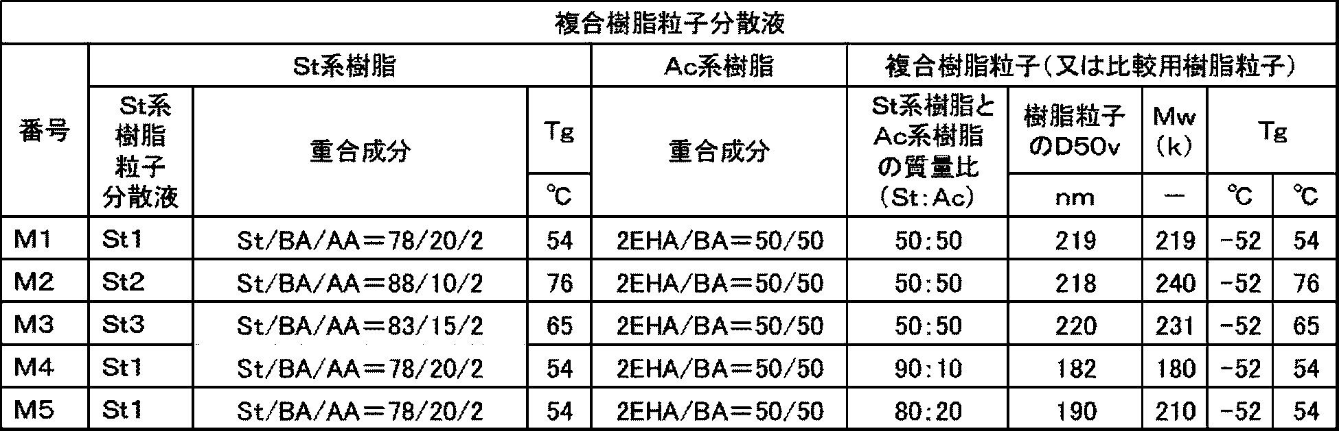
[加圧相転移樹脂トナー(1)の調製]
・複合樹脂粒子分散液(M1) :504部
・イオン交換水 :710部
・アニオン性界面活性剤(ダウ・ケミカル社製、Dowfax2A1): 1部
加圧相転移樹脂トナー(1)の調製と同様にして、但し複合樹脂粒子分散液及びスチレン系樹脂粒子分散液を表3に記載の通りに変更して、加圧相転移樹脂トナー(2)~(5)を調製した。
加圧相転移樹脂トナーが圧力によって相転移しやすいことを示す指標である温度差(T1-T3)を求めた。各加圧相転移樹脂トナーを試料にして、フローテスター(島津製作所製、CFT-500)にて、温度T1及び温度T3を測定し、温度差(T1-T3)を算出した。表3に温度差(T1-T3)を示す。
記録媒体として富士フイルムビジネスイノベーション(株)製のハガキ用紙V424を用意した。富士フイルムビジネスイノベーション(株)製の画像形成装置DocuCentre C7550I並びに富士フイルムビジネスイノベーション(株)製の市販品のイエロートナー、マゼンタトナー、シアントナー及びブラックトナーを用いて、ハガキ用紙の片面に、黒色文字とフルカラー写真画像とが混在した面積密度30%の画像を形成し、画像を定着させた。
ハガキ用紙の画像形成面の全体に、加圧相転移樹脂トナーを付与量3g/m2となるように散布し、ベルトロール型固定機を通過させて、ハガキ用紙の画像形成面に加圧相転移樹脂トナーを固定させ、加圧相転移樹脂トナーの層を形成した。
画像形成面に加圧相転移樹脂トナーの層を有するハガキ用紙を、トッパン・フォームズ(株)製のシーラーPRESSLE multiIIを用いて、画像形成面が内側になるように二つ折りにし、二つ折りにしたハガキ用紙に圧力を印加し、内側の画像形成面どうしを圧力90MPaで接着した。
上記の装置及び条件で、画像形成面が内側になるように二つ折りにされ、且つ画像形成面どうしが接着されたハガキを連続して10通作製した。10通目のハガキを長辺方向に幅15mmで裁断し長方形の試験片を作製して、90度剥離試験を行った。90度剥離試験の剥離速度は20mm/分とし、測定開始後10mmから50mmまでの荷重(N)を0.4mm間隔で採取し、その平均を算出し、さらに試験片3枚の荷重(N)を平均した。剥離に要する荷重(N)を下記のとおり分類した。表3に結果を示す。
B:0.6N以上、0.8N未満
C:0.4N以上、0.6N未満
D:0.2N以上、0.4N未満
E:0.2N未満

試験例1~3と試験例4~5との加圧相転移樹脂トナーの比較により、海島構造の島相の平均径が小さくなると、接着性に優れることがわかる。
Claims (11)
- 圧力によって相転移することで接着性を生じる加圧相転移樹脂トナーを用いて電子写真方式によってシート状の印刷媒体の一部に接着部を形成する工程と、
印刷媒体の一部を折り曲げて前記接着部が形成された印刷媒体の部分を印刷媒体の他の部分と接着させて立体部分を形成する工程と、
を備える立体物の製造方法。 - 前記接着部を形成する工程では、印刷媒体に画像も形成する、
請求項1に記載の立体物の製造方法。 - 前記接着部を形成する工程では、第一接着部と、前記第一接着部と比して接着力の弱い第二接着部と、を含んでいる前記接着部を印刷媒体に形成する、
請求項1又は2に記載の立体物の製造方法。 - 前記接着部を形成する工程では、前記第一接着部のトナー濃度を、前記第二接着部のトナー濃度と比して高くして前記接着部を印刷媒体に形成する、
請求項3に記載の立体物の製造方法。 - 前記接着部を形成する工程では、前記第一接着部から前記第二接着部まで、接着力が変化するように前記接着部を印刷媒体に形成する、
請求項4に記載の立体物の製造方法。 - 前記接着部を形成する工程では、互いに離間すると共に色が異なる複数の前記接着部を印刷媒体に形成する、
請求項1~5の何れか1項に記載の立体物の製造方法。 - 前記接着部を形成する工程では、印刷媒体の表面と、印刷媒体の裏面とに色が異なる前記接着部を形成する、
請求項6に記載の立体物の製造方法。 - 前記立体部分を形成する工程では、印刷媒体の一部を折り曲げて印刷媒体を平面状として押圧することで、前記接着部が形成された印刷媒体の部分を印刷媒体の他の部分と接着させる、
請求項1~7の何れか1項に記載の立体物の製造方法。 - 前記加圧相転移樹脂トナーは、
スチレン及びその他のビニルモノマーを重合成分に含むスチレン系樹脂と、
少なくとも2種の(メタ)アクリル酸エステルを重合成分に含み、重合成分全体に占める(メタ)アクリル酸エステルの質量割合が90質量%以上である(メタ)アクリル酸エステル系樹脂と、を含み、
少なくとも2つのガラス転移温度を有し、最も低いガラス転移温度と最も高いガラス転移温度との差が30℃以上である、
請求項1~8の何れか1項に記載の立体物の製造方法。 - 前記加圧相転移樹脂トナーは、加圧相転移樹脂トナー粒子を含み、
前記加圧相転移樹脂トナー粒子は、前記スチレン系樹脂を含む海相と、前記海相に分散した前記(メタ)アクリル酸エステル系樹脂を含む島相とを有する、
請求項9に記載の立体物の製造方法。 - 前記島相の平均径が200nm以上500nm以下である、請求項10に記載の立体物の製造方法。
Priority Applications (3)
| Application Number | Priority Date | Filing Date | Title |
|---|---|---|---|
| EP22872527.1A EP4406892A4 (en) | 2021-09-22 | 2022-07-13 | PROCESS FOR MANUFACTURING THREE-DIMENSIONAL OBJECTS |
| CN202280037325.XA CN117425607A (zh) | 2021-09-22 | 2022-07-13 | 立体物的制造方法 |
| US18/516,051 US20240092073A1 (en) | 2021-09-22 | 2023-11-21 | Method for producing three-dimensional object |
Applications Claiming Priority (2)
| Application Number | Priority Date | Filing Date | Title |
|---|---|---|---|
| JP2021-154745 | 2021-09-22 | ||
| JP2021154745A JP7815670B2 (ja) | 2021-09-22 | 2021-09-22 | 立体物の製造方法 |
Related Child Applications (1)
| Application Number | Title | Priority Date | Filing Date |
|---|---|---|---|
| US18/516,051 Continuation US20240092073A1 (en) | 2021-09-22 | 2023-11-21 | Method for producing three-dimensional object |
Publications (1)
| Publication Number | Publication Date |
|---|---|
| WO2023047771A1 true WO2023047771A1 (ja) | 2023-03-30 |
Family
ID=85720460
Family Applications (1)
| Application Number | Title | Priority Date | Filing Date |
|---|---|---|---|
| PCT/JP2022/027560 Ceased WO2023047771A1 (ja) | 2021-09-22 | 2022-07-13 | 立体物の製造方法 |
Country Status (5)
| Country | Link |
|---|---|
| US (1) | US20240092073A1 (ja) |
| EP (1) | EP4406892A4 (ja) |
| JP (1) | JP7815670B2 (ja) |
| CN (1) | CN117425607A (ja) |
| WO (1) | WO2023047771A1 (ja) |
Cited By (1)
| Publication number | Priority date | Publication date | Assignee | Title |
|---|---|---|---|---|
| EP4446813A1 (en) * | 2023-04-10 | 2024-10-16 | FUJIFILM Business Innovation Corp. | Plate data forming device, plate data forming program, pressure-bonding device, and plate data forming method |
Citations (6)
| Publication number | Priority date | Publication date | Assignee | Title |
|---|---|---|---|---|
| JPH07101184A (ja) * | 1993-10-01 | 1995-04-18 | Tadanao Ashiya | 湾曲変形を抑制した貼り合わせ葉書 |
| JP2005298551A (ja) * | 2004-04-06 | 2005-10-27 | Daio Paper Corp | 擬似接着用紙およびその製造方法 |
| JP2015044294A (ja) | 2013-08-27 | 2015-03-12 | 有限会社篠原紙工 | ポップアップ紙製品の製造方法 |
| JP2021018425A (ja) * | 2019-07-17 | 2021-02-15 | 富士ゼロックス株式会社 | 圧力応答性粒子、カートリッジ、印刷物の製造装置、印刷物の製造方法、印刷物、印刷物製造用シート、及び印刷物製造用シートの製造方法 |
| JP2021140121A (ja) * | 2020-03-09 | 2021-09-16 | 富士フイルムビジネスイノベーション株式会社 | 圧力応答性粒子、カートリッジ、印刷物の製造装置、印刷物の製造方法、印刷物、印刷物製造用シート、及び印刷物製造用シートの製造方法 |
| JP2021154745A (ja) | 2017-06-16 | 2021-10-07 | キヤノン株式会社 | 光プリントヘッドを備える画像形成装置 |
Family Cites Families (3)
| Publication number | Priority date | Publication date | Assignee | Title |
|---|---|---|---|---|
| JP2000177017A (ja) * | 1998-12-17 | 2000-06-27 | Minolta Co Ltd | 3次元造形物の製造方法 |
| JP2004142363A (ja) | 2002-10-28 | 2004-05-20 | Dainippon Printing Co Ltd | ポップアップ式カード |
| JP5328594B2 (ja) * | 2009-10-04 | 2013-10-30 | 内田紙工業株式会社 | 見開き構造体 |
-
2021
- 2021-09-22 JP JP2021154745A patent/JP7815670B2/ja active Active
-
2022
- 2022-07-13 EP EP22872527.1A patent/EP4406892A4/en active Pending
- 2022-07-13 WO PCT/JP2022/027560 patent/WO2023047771A1/ja not_active Ceased
- 2022-07-13 CN CN202280037325.XA patent/CN117425607A/zh active Pending
-
2023
- 2023-11-21 US US18/516,051 patent/US20240092073A1/en active Pending
Patent Citations (6)
| Publication number | Priority date | Publication date | Assignee | Title |
|---|---|---|---|---|
| JPH07101184A (ja) * | 1993-10-01 | 1995-04-18 | Tadanao Ashiya | 湾曲変形を抑制した貼り合わせ葉書 |
| JP2005298551A (ja) * | 2004-04-06 | 2005-10-27 | Daio Paper Corp | 擬似接着用紙およびその製造方法 |
| JP2015044294A (ja) | 2013-08-27 | 2015-03-12 | 有限会社篠原紙工 | ポップアップ紙製品の製造方法 |
| JP2021154745A (ja) | 2017-06-16 | 2021-10-07 | キヤノン株式会社 | 光プリントヘッドを備える画像形成装置 |
| JP2021018425A (ja) * | 2019-07-17 | 2021-02-15 | 富士ゼロックス株式会社 | 圧力応答性粒子、カートリッジ、印刷物の製造装置、印刷物の製造方法、印刷物、印刷物製造用シート、及び印刷物製造用シートの製造方法 |
| JP2021140121A (ja) * | 2020-03-09 | 2021-09-16 | 富士フイルムビジネスイノベーション株式会社 | 圧力応答性粒子、カートリッジ、印刷物の製造装置、印刷物の製造方法、印刷物、印刷物製造用シート、及び印刷物製造用シートの製造方法 |
Non-Patent Citations (1)
| Title |
|---|
| See also references of EP4406892A4 |
Cited By (1)
| Publication number | Priority date | Publication date | Assignee | Title |
|---|---|---|---|---|
| EP4446813A1 (en) * | 2023-04-10 | 2024-10-16 | FUJIFILM Business Innovation Corp. | Plate data forming device, plate data forming program, pressure-bonding device, and plate data forming method |
Also Published As
| Publication number | Publication date |
|---|---|
| JP2023046055A (ja) | 2023-04-03 |
| EP4406892A1 (en) | 2024-07-31 |
| US20240092073A1 (en) | 2024-03-21 |
| EP4406892A4 (en) | 2025-09-17 |
| JP7815670B2 (ja) | 2026-02-18 |
| CN117425607A (zh) | 2024-01-19 |
Similar Documents
| Publication | Publication Date | Title |
|---|---|---|
| US12251956B2 (en) | Method for producing printed material and system for producing printed material | |
| US11235608B2 (en) | Method for forming printed material and system for forming printed material | |
| US11104538B1 (en) | Method for producing printed material and system for producing printed material | |
| JP7516991B2 (ja) | 圧力応答性粒子、カートリッジ、印刷物の製造装置、印刷物の製造方法、印刷物、印刷物製造用シート、及び印刷物製造用シートの製造方法 | |
| JP7480539B2 (ja) | 印刷物の製造方法及び印刷物の製造システム | |
| WO2023047771A1 (ja) | 立体物の製造方法 | |
| JP2022042364A (ja) | 圧力応答性粒子、カートリッジ、印刷物の製造装置、印刷物の製造方法、印刷物、印刷物製造用シート、及び印刷物製造用シートの製造方法 | |
| US11235593B2 (en) | Method for forming printed material and system for forming printed material | |
| JP2022042366A (ja) | 圧力応答性粒子、カートリッジ、印刷物の製造装置、印刷物の製造方法、印刷物、印刷物製造用シート、及び印刷物製造用シートの製造方法 | |
| US12420519B2 (en) | Pressure sensitive adhesive particle, cartridge, apparatus for producing printed material, method for producing printed material, printed material, sheet for producing printed material, and method for producing sheet for producing printed material | |
| JP7593127B2 (ja) | 圧力応答性粒子、カートリッジ、印刷物の製造装置、印刷物の製造方法、印刷物、印刷物製造用シート、及び印刷物製造用シートの製造方法 | |
| JP7631980B2 (ja) | 印刷物、及び印刷物の製造方法 | |
| US20240337978A1 (en) | Image forming system, image forming method, and crimping toner image forming apparatus | |
| EP4067100B1 (en) | Printed material and method for producing printed material | |
| US20240337979A1 (en) | Image forming system, image forming method, and crimping toner image forming apparatus | |
| JP2023047239A (ja) | 圧着印刷物 | |
| JP2022150041A (ja) | 圧力応答性粒子の製造方法、印刷物の製造方法、印刷物製造用シートの製造方法、及び、圧力応答性粒子 | |
| JP2022110880A (ja) | 圧力応答性粒子、接着材料、印刷物の製造装置、印刷物の製造方法、印刷物、印刷物製造用シート、及び、印刷物製造用シートの製造方法 |
Legal Events
| Date | Code | Title | Description |
|---|---|---|---|
| 121 | Ep: the epo has been informed by wipo that ep was designated in this application |
Ref document number: 22872527 Country of ref document: EP Kind code of ref document: A1 |
|
| WWE | Wipo information: entry into national phase |
Ref document number: 202280037325.X Country of ref document: CN |
|
| WWE | Wipo information: entry into national phase |
Ref document number: 2022872527 Country of ref document: EP |
|
| NENP | Non-entry into the national phase |
Ref country code: DE |
|
| ENP | Entry into the national phase |
Ref document number: 2022872527 Country of ref document: EP Effective date: 20240422 |