WO2023047879A1 - ワーク位置判定装置、レーザ加工装置、及びワーク位置判定方法 - Google Patents
ワーク位置判定装置、レーザ加工装置、及びワーク位置判定方法 Download PDFInfo
- Publication number
- WO2023047879A1 WO2023047879A1 PCT/JP2022/031947 JP2022031947W WO2023047879A1 WO 2023047879 A1 WO2023047879 A1 WO 2023047879A1 JP 2022031947 W JP2022031947 W JP 2022031947W WO 2023047879 A1 WO2023047879 A1 WO 2023047879A1
- Authority
- WO
- WIPO (PCT)
- Prior art keywords
- unit
- workpiece
- work
- imaging unit
- imaging
- Prior art date
- Legal status (The legal status is an assumption and is not a legal conclusion. Google has not performed a legal analysis and makes no representation as to the accuracy of the status listed.)
- Ceased
Links
Images






Classifications
-
- B—PERFORMING OPERATIONS; TRANSPORTING
- B23—MACHINE TOOLS; METAL-WORKING NOT OTHERWISE PROVIDED FOR
- B23Q—DETAILS, COMPONENTS, OR ACCESSORIES FOR MACHINE TOOLS, e.g. ARRANGEMENTS FOR COPYING OR CONTROLLING; MACHINE TOOLS IN GENERAL CHARACTERISED BY THE CONSTRUCTION OF PARTICULAR DETAILS OR COMPONENTS; COMBINATIONS OR ASSOCIATIONS OF METAL-WORKING MACHINES, NOT DIRECTED TO A PARTICULAR RESULT
- B23Q17/00—Arrangements for observing, indicating or measuring on machine tools
- B23Q17/24—Arrangements for observing, indicating or measuring on machine tools using optics or electromagnetic waves
- B23Q17/2428—Arrangements for observing, indicating or measuring on machine tools using optics or electromagnetic waves for measuring existing positions of tools or workpieces
-
- B—PERFORMING OPERATIONS; TRANSPORTING
- B23—MACHINE TOOLS; METAL-WORKING NOT OTHERWISE PROVIDED FOR
- B23K—SOLDERING OR UNSOLDERING; WELDING; CLADDING OR PLATING BY SOLDERING OR WELDING; CUTTING BY APPLYING HEAT LOCALLY, e.g. FLAME CUTTING; WORKING BY LASER BEAM
- B23K26/00—Working by laser beam, e.g. welding, cutting or boring
- B23K26/02—Positioning or observing the workpiece, e.g. with respect to the point of impact; Aligning, aiming or focusing the laser beam
- B23K26/03—Observing, e.g. monitoring, the workpiece
- B23K26/032—Observing, e.g. monitoring, the workpiece using optical means
-
- B—PERFORMING OPERATIONS; TRANSPORTING
- B23—MACHINE TOOLS; METAL-WORKING NOT OTHERWISE PROVIDED FOR
- B23K—SOLDERING OR UNSOLDERING; WELDING; CLADDING OR PLATING BY SOLDERING OR WELDING; CUTTING BY APPLYING HEAT LOCALLY, e.g. FLAME CUTTING; WORKING BY LASER BEAM
- B23K26/00—Working by laser beam, e.g. welding, cutting or boring
- B23K26/60—Preliminary treatment
-
- B—PERFORMING OPERATIONS; TRANSPORTING
- B23—MACHINE TOOLS; METAL-WORKING NOT OTHERWISE PROVIDED FOR
- B23K—SOLDERING OR UNSOLDERING; WELDING; CLADDING OR PLATING BY SOLDERING OR WELDING; CUTTING BY APPLYING HEAT LOCALLY, e.g. FLAME CUTTING; WORKING BY LASER BEAM
- B23K26/00—Working by laser beam, e.g. welding, cutting or boring
- B23K26/70—Auxiliary operations or equipment
-
- G—PHYSICS
- G05—CONTROLLING; REGULATING
- G05B—CONTROL OR REGULATING SYSTEMS IN GENERAL; FUNCTIONAL ELEMENTS OF SUCH SYSTEMS; MONITORING OR TESTING ARRANGEMENTS FOR SUCH SYSTEMS OR ELEMENTS
- G05B19/00—Program-control systems
- G05B19/02—Program-control systems electric
- G05B19/18—Numerical control [NC], i.e. automatically operating machines, in particular machine tools, e.g. in a manufacturing environment, so as to execute positioning, movement or co-ordinated operations by means of program data in numerical form
- G05B19/19—Numerical control [NC], i.e. automatically operating machines, in particular machine tools, e.g. in a manufacturing environment, so as to execute positioning, movement or co-ordinated operations by means of program data in numerical form characterised by positioning or contouring control systems, e.g. to control position from one programmed point to another or to control movement along a programmed continuous path
-
- G—PHYSICS
- G05—CONTROLLING; REGULATING
- G05B—CONTROL OR REGULATING SYSTEMS IN GENERAL; FUNCTIONAL ELEMENTS OF SUCH SYSTEMS; MONITORING OR TESTING ARRANGEMENTS FOR SUCH SYSTEMS OR ELEMENTS
- G05B19/00—Program-control systems
- G05B19/02—Program-control systems electric
- G05B19/18—Numerical control [NC], i.e. automatically operating machines, in particular machine tools, e.g. in a manufacturing environment, so as to execute positioning, movement or co-ordinated operations by means of program data in numerical form
- G05B19/401—Numerical control [NC], i.e. automatically operating machines, in particular machine tools, e.g. in a manufacturing environment, so as to execute positioning, movement or co-ordinated operations by means of program data in numerical form characterised by control arrangements for measuring, e.g. calibration and initialisation, measuring workpiece for machining purposes
-
- B—PERFORMING OPERATIONS; TRANSPORTING
- B23—MACHINE TOOLS; METAL-WORKING NOT OTHERWISE PROVIDED FOR
- B23K—SOLDERING OR UNSOLDERING; WELDING; CLADDING OR PLATING BY SOLDERING OR WELDING; CUTTING BY APPLYING HEAT LOCALLY, e.g. FLAME CUTTING; WORKING BY LASER BEAM
- B23K37/00—Auxiliary devices or processes, not specially adapted for a procedure covered by only one of the other main groups of this subclass
- B23K37/04—Auxiliary devices or processes, not specially adapted for a procedure covered by only one of the other main groups of this subclass for holding or positioning work
- B23K37/0408—Auxiliary devices or processes, not specially adapted for a procedure covered by only one of the other main groups of this subclass for holding or positioning work for planar work
-
- G—PHYSICS
- G05—CONTROLLING; REGULATING
- G05B—CONTROL OR REGULATING SYSTEMS IN GENERAL; FUNCTIONAL ELEMENTS OF SUCH SYSTEMS; MONITORING OR TESTING ARRANGEMENTS FOR SUCH SYSTEMS OR ELEMENTS
- G05B2219/00—Program-control systems
- G05B2219/30—Nc systems
- G05B2219/37—Measurements
- G05B2219/37575—Pre-process, measure workpiece before machining
-
- G—PHYSICS
- G05—CONTROLLING; REGULATING
- G05B—CONTROL OR REGULATING SYSTEMS IN GENERAL; FUNCTIONAL ELEMENTS OF SUCH SYSTEMS; MONITORING OR TESTING ARRANGEMENTS FOR SUCH SYSTEMS OR ELEMENTS
- G05B2219/00—Program-control systems
- G05B2219/30—Nc systems
- G05B2219/45—Nc applications
- G05B2219/45041—Laser cutting
Definitions
- the present invention relates to a work position determination device, a laser processing device, and a work position determination method.
- a laser processing apparatus includes a processing unit that laser-processes a plate-shaped work having a flat portion by irradiating the work with a laser beam.
- laser processing may be further performed on a workpiece that has already been processed by another processing apparatus such as a press machine.
- another processing apparatus such as a press machine.
- correcting the coordinate system of the processing portion for example, the position of a reference hole formed in the work or the position of the outer peripheral end surface of the work is detected, and the coordinate system of the processing portion is corrected based on the detection result.
- a sensor such as a touch probe or camera is used to detect the reference hole or end face of the workpiece.
- This sensor is moved along the flat surface of the workpiece by a drive unit.
- a control unit that controls the driving unit moves the sensor along the workpiece based on an estimated position given in advance as positional information of the reference hole or the end surface.
- the detection result by the sensor is sent to the control section, and the control section determines whether or not the boundary has been detected.
- the coordinates of one point on the boundary are obtained based on the detection result, and the driving unit repeatedly moves the sensor to obtain the coordinates of the next point on the boundary (see, for example, Patent Document 1).
- An object of the present invention is to provide a work position determination device, a laser processing device, and a work position determination method that can shorten the time required to determine the position of a work.
- a work position determination device includes an imaging unit, a driving unit that relatively moves the imaging unit with respect to a work having a flat surface in a plane direction parallel to the flat surface, and an imaging unit that is configured in a plan view.
- a control unit that controls the driving unit to move along a prescribed trajectory that passes through a plurality of locations of the boundary part in the plane part, and image information captured by the imaging unit while the imaging unit moves along the prescribed trajectory, and a storage unit for storing coordinate information of the imaging unit when each image information was captured, and based on the image information and the coordinate information stored in the storage unit, the position corresponding to the boundary portion in the planar direction of the workpiece is determined.
- a position determination unit and a deviation determination unit that determines deviation of the workpiece from the reference position based on the determination result of the position determination unit.
- a laser processing apparatus is a laser processing apparatus including a processing unit that processes a work having a flat portion by irradiating the work with a laser beam, and the work position determination device of the above-described aspect. Prepare.
- the work position determination method provides a specified trajectory for a work having a flat portion in a plane direction parallel to the flat portion and passing through a plurality of locations of the boundary portion of the flat portion in a plan view.
- the image information captured by the image capturing unit while the image capturing unit moves along a prescribed trajectory, and the coordinate information of the image capturing unit when each image information was captured are stored.
- determining the position corresponding to the boundary portion in the planar direction of the work based on the stored image information and coordinate information; and determining the position of the work relative to the reference position based on the determination result of the position corresponding to the boundary portion. determining the deviation.
- the imaging unit is moved along a prescribed locus, and image information captured by the imaging unit during this movement is stored in the storage unit. Since the position of the workpiece is obtained based on the stored image information, feedback control of the driving section based on the image information captured by the imaging section is not required. For this reason, it is not necessary to consider delays in image processing calculations and delays in communication such as movement commands with respect to the movement of the imaging unit, so the time required to determine the position of the workpiece can be shortened. As a result, the work efficiency can be improved.
- the imaging optical system in the imaging unit is provided coaxially with the laser light irradiation optical system in the processing unit of the laser processing apparatus that processes the work by irradiating the work with laser light.
- control unit is arranged such that the imaging unit moves along a prescribed trajectory passing through a plurality of locations on the inner peripheral edge of the reference hole in plan view while capturing an image of the reference hole provided in the work. and the position determination unit may calculate the position of the center of the reference hole in the workpiece. According to this aspect, by moving the imaging section along a prescribed trajectory, it is possible to efficiently acquire image information at a plurality of locations on the inner peripheral edge of the reference hole, and accurately calculate the center position from the image information.
- control unit may control the driving unit so that the imaging unit moves along a trajectory that draws a prescribed point-symmetrical shape or line-symmetrical shape in plan view. According to this aspect, it is possible to efficiently acquire image information at a plurality of locations on the inner peripheral edge of the reference hole. Furthermore, by imaging the boundary portion from a plurality of directions, the robustness of the determination accuracy by the position determination unit can be improved. Further, in the work position determination device of the aspect described above, the observation range of one image captured by the imaging section may be smaller than the reference hole. According to this aspect, since the observation range is smaller than the reference hole, the image information of the inner peripheral edge of the reference hole can be obtained with high accuracy.
- the control unit drives the imaging unit to move along a prescribed trajectory that passes through a plurality of locations on the edge in plan view while capturing an image of the edge corresponding to the side of the workpiece. and the position determination unit may determine the position of the edge on the workpiece. According to this aspect, it is possible to efficiently acquire the image information of the end portion corresponding to the side of the workpiece by moving the imaging section along the prescribed locus. Further, in the workpiece position determination device of the aspect described above, the control unit may control the driving unit so that the imaging unit moves along a prescribed linear, curved, zigzag, or spiral trajectory in plan view. good. According to this aspect, it is possible to efficiently acquire image information at a plurality of locations at the end of the work.
- the position determination unit selects image information used for determining the position of the boundary portion from among the plurality of image information captured by the imaging unit, and selects image information corresponding to the selected image information.
- the position of the boundary portion may be determined based on the coordinate information. According to this aspect, image information less than all the captured image information is processed, so it is possible to speed up the determination process.
- the shift determination unit determines the shift amount in each of the first direction and the second direction orthogonal to the reference position from the determination result of the position of at least one boundary portion. good too.
- the shift determination unit determines, from the determination results of the positions of the boundary portions at least three locations, the shift amount in each of the first and second directions perpendicular to the reference position, and the shift amount in the first direction.
- An amount of rotation about an axis in a third direction orthogonal to the direction and the second direction may be determined. According to this aspect, since the amount of shift in each of the first and second directions and the amount of rotation about the axis in the third direction are determined, it is possible to accurately determine the deviation of the workpiece from the reference position.
- FIG. 4 is a diagram showing an example of the relationship between a reference hole and an observation range of an imaging unit
- FIG. 5 is a diagram showing an example of a relationship between an end portion and an observation range of an imaging unit
- A) and (B) are diagrams showing examples of prescribed trajectories set for reference holes.
- A) and (B) are diagrams showing examples of prescribed trajectories set for reference holes.
- FIG. 10 is a diagram showing another example of an imaging unit;
- FIG. 10 is a diagram showing another example of an imaging unit;
- FIG. 10 is a diagram showing an example of selecting image information in a position determination unit;
- FIG. 10 is a diagram showing an example in which a work is arranged at a reference position; It is a figure which shows an example of the determination result by a deviation
- 4 is a flowchart showing an example of a workpiece position determination method according to the embodiment;
- the direction indicated by the arrow is referred to as the + direction (eg, +X direction, +X side), and the direction opposite to the direction indicated by the arrow is referred to as the - direction (eg, -X direction, -X side). called.
- FIG. 1 is a diagram showing an example of a workpiece position determination device 40 and a laser processing device 1 according to an embodiment.
- the workpiece position determination device 40 is included in the configuration of the laser processing device 1 .
- the work position determination device 40 includes a head driving section (driving section) 20 , an imaging section 30 , a control section 41 , a storage section 42 , a position determination section 43 and a shift determination section 44 . Each part constituting the workpiece position determination device 40 will be described as appropriate when describing the laser processing device 1 .
- the laser processing device 1 includes a processing section 100 .
- the processing unit 100 can irradiate a laser beam L1 to cut a plate-like workpiece W to be processed.
- the processing unit 100 performs laser processing (cutting processing, drilling processing) on the work W carried into the processing area. Carrying in the unprocessed work W to a position where laser processing by the processing unit 100 is possible and carrying out the processed work W from the position may be performed by moving a processing pallet 50, which will be described later, or not shown. It may be performed by a loader device or the like.
- the laser processing apparatus 1 may be, for example, a multi-tasking machine in which the processing unit 100 is arranged adjacent to another processing apparatus such as a punch press.
- the processing unit 100 includes a laser head 10, a lens driving unit 21, and a processing palette 50. Further, the processing section 100 shares the work position determining device 40 with the head driving section 20 and the imaging section 30 . That is, the processing section 100 includes a head driving section 20 and an imaging section 30 .
- the laser head 10 has a head body 11 and a nozzle 12, and cuts and drills the work W by irradiating the flat portion Wa of the work W with a laser beam L1. When cutting the workpiece W, the laser head 10 irradiates the laser beam L1 and is driven by the head drive unit 20 to move the laser beam L1 along a predetermined cutting line.
- the laser head 10 is connected to a laser light source such as a laser oscillator 60 or the like.
- the laser oscillator 60 generates infrared laser light, for example, as the laser light L1.
- the laser light source for example, a carbon dioxide gas laser light source or a solid laser light source may be used.
- the laser head 10 has an irradiation optical system 61 .
- the irradiation optical system 61 guides and then converges the laser beam L1 generated by the laser oscillator 60 .
- the irradiation optical system 61 has an optical fiber 62 , a collimator 63 , a beam splitter 64 and a condenser lens 65 .
- An optical fiber 62 connects the laser oscillator 60 and the laser head 10 .
- a laser beam L1 from a laser oscillator 60 is introduced into the laser head 10 via an optical fiber 62 .
- the collimator 63 converts the laser light L1 from the laser oscillator 60 into parallel light or brings it closer to parallel light.
- the beam splitter 64 is arranged at a position where the laser beam L1 that has passed through the collimator 63 is incident.
- the beam splitter 64 is a wavelength selection mirror having characteristics of reflecting the laser beam L1 and transmitting the illumination laser beam L2, which will be described later.
- the laser beam L 1 is reflected by the beam splitter 64 , the optical path is bent from the X direction to the Z direction ( ⁇ Z side) by about 90 degrees, and enters the condenser lens 65 .
- the condenser lens 65 condenses the laser beam L1 from the collimator 63 .
- the condenser lens 65 is movable along the optical axis 63a.
- the laser beam L1 is converged by the irradiation optical system 61 so as to form a spot with a predetermined diameter on the workpiece W. As shown in FIG.
- the diameter of the spot can be adjusted, for example, by moving the condenser lens 65 with the lens drive section 21 .
- the lens drive section 21 is controlled by the control section 41 .
- the head main body 11 is arranged in the processing section 100 above (+Z side) the work W arranged in the processing area.
- the head main body 11 is driven by the head driving section 20 so as to move relative to the workpiece W in the X, Y and Z directions.
- the head driving unit 20 has, for example, a gantry movable in the X direction, a slider movable in the Y direction with respect to the gantry, and an elevating unit movable in the Z direction with respect to the slider.
- the head drive unit 20 moves the head main body 11 to predetermined positions in the X, Y and Z directions by driving the gantry, the slider, and the elevating unit, respectively.
- the head drive unit 20 is not limited to the above configuration, and may have another configuration such as a robot arm.
- the nozzle 12 is attached to the lower side (-Z side) of the head body 11 so as to face the -Z direction (downward), and irradiate the laser light L1 in the -Z direction (downward).
- the nozzle 12 is connected to an assist gas supply unit (not shown) through a gas supply pipe or the like, and supplies an assist gas (for example, nitrogen gas) from the assist gas supply unit toward a portion to be irradiated with the laser beam L1. supplied to W.
- an assist gas for example, nitrogen gas
- the processing unit 100 can illuminate the workpiece W with the illumination laser beam L2.
- the laser array 70 emits illumination laser light L2 having a wavelength different from that of the laser light L1 from a plurality of laser elements.
- the driving of the laser array 70 is controlled by the control unit 41 and stored in the housing 73 .
- the illumination optical system 71 illuminates the work W with the illumination laser light L2 generated by the laser array 70 .
- the illumination optical system 71 includes a collimator 72 , a half mirror 74 , a beam splitter 64 and a condenser lens 65 .
- the illumination optical system 71 shares the beam splitter 64 and the condensing lens 65 with the irradiation optical system 61 , and performs epi-illumination via the condensing lens 65 .
- the optical axis 72a on the light exit side of the illumination optical system 71 and the optical axis 63a on the light exit side of the irradiation optical system 61 are coaxial, and the illumination laser light L2 travels along the same optical path as the laser light L1.
- the workpiece W is irradiated.
- the collimator 72 is arranged at a position where the illumination laser light L2 from the laser array 70 is incident.
- the collimator 72 converts the illumination laser light L2 from the laser array 70 into parallel light or brings it closer to parallel light.
- the half mirror 74 is a reflecting/transmitting member having a characteristic of partially reflecting and partially transmitting the illumination laser beam L2.
- the illumination laser beam L 2 is reflected by the half mirror 74 , the optical path is bent from the X direction to the Z direction ( ⁇ Z side) by about 90 degrees, and enters the beam splitter 64 .
- the illumination laser beam L2 is condensed by the condensing lens 65 to illuminate the workpiece W. As shown in FIG.
- the area illuminated by the illumination laser beam L2 is set so as to include a portion of the workpiece W irradiated with the laser beam L1. Also, the area illuminated by the illumination laser beam L2 can be changed by moving the condenser lens 65 by the lens drive unit 21 .
- the imaging unit 30 images the plane portion Wa of the work W. Further, the imaging unit 30 images the cut portion of the work W irradiated with the laser beam L1.
- the imaging unit 30 moves in the X direction, the Y direction, and the Z direction integrally with the head body 11 . That is, the head drive unit 20 is a drive unit that relatively moves the imaging unit in a plane direction parallel to the plane portion Wa of the work W. As shown in FIG.
- the imaging unit 30 includes an imaging optical system 31 and an imaging device 32 , and detects light (returned light) from the workpiece W with the imaging device 32 via the imaging optical system 31 .
- a CCD or CMOS image sensor is used as the imaging device 32 to capture an image formed by the imaging optical system 31 .
- the imaging element 32 is provided with a plurality of pixels arranged two-dimensionally. Each pixel is provided with a light receiving element such as a photodiode.
- the image sensor 32 sequentially reads charges (signals) generated in each pixel by light (return light) incident on the light receiving element, amplifies the read signals, A/D converts them, and arranges them in an image format. , to generate digital data of the captured image.
- the imaging optical system 31 has a condenser lens 65 , a beam splitter 64 , a half mirror 74 , a wavelength selection filter 33 and an imaging lens 34 .
- the imaging optical system 31 shares the condenser lens 65 and the beam splitter 64 with the irradiation optical system 61 .
- the imaging unit 30 can image the workpiece W coaxially with the irradiation optical system 61 . That is, the optical axis 34 a of the imaging optical system 31 and the optical axis 63 a of the irradiation optical system 61 are coaxial at the condenser lens 65 and the beam splitter 64 .
- the imaging device 32 is held by, for example, an alignment device 35 and its position with respect to the imaging optical system 31 can be adjusted by the alignment device 35 .
- the alignment device 35 moves the imaging element 32.
- the position of the imaging element 32 can be adjusted to the focal point of the imaging optical system 31 .
- the image forming lens 34 may be moved in a direction parallel to the optical axis 34a to align the focus position with the imaging device 32.
- Return light from the workpiece W passes through the condenser lens 65 and enters the beam splitter 64 .
- the returned light includes, for example, the light reflected and scattered by the workpiece W in the illumination laser light L2 and the light derived from the irradiation of the laser light L1.
- light originating from the illumination laser beam L 2 passes through the beam splitter 64 and enters the half mirror 74 .
- the light originating from the irradiation of the laser beam L 1 is reflected by the beam splitter 64 and removed from the optical path from the beam splitter 64 to the half mirror 74 .
- the return light that has entered the half mirror 74 is divided into light that passes through the half mirror 74 and enters the wavelength selection filter 33 and light that is reflected by the half mirror 74 .
- the wavelength selection filter 33 has a characteristic of reflecting light in the wavelength band reflected by the workpiece W due to illumination with the illumination laser light L2. Further, the wavelength selection filter 33 has a characteristic of transmitting light in the wavelength band emitted from the workpiece W by irradiation with the laser beam L1.
- the wavelength selection filter 33 is, for example, a dichroic mirror or a notch filter. That is, the light derived from the illumination laser beam L2 among the returned light is reflected by the wavelength selection filter 33 and enters the imaging lens 34 .
- the imaging lens 34 converges the light reflected by the wavelength selection filter 33 onto the imaging device 32 .
- the imaging lens 34 and the condenser lens 65 project an image of the workpiece W onto the imaging device 32 .
- the imaging unit 30 mainly generates digital data of a captured image according to the light (return light) in the wavelength band reflected by the workpiece W due to the illumination laser beam L2.
- the control unit 41 of the work position determination device 40 controls the image pickup unit 30 (head main body 11) to move the boundary portion Wb (see FIG. 3 etc.) of the flat surface portion Wa of the work W in plan view (when viewed in the Z direction).
- the head drive unit 20 is controlled so as to move along a prescribed locus that passes through a plurality of locations.
- the control unit 41 performs overall control of the processing unit 100 of the laser processing apparatus 1 . The details of the boundary portion Wb will be described later.
- the storage unit 42 stores image information captured by the image capturing unit 30 while the image capturing unit 30 moves along the prescribed locus, and coordinate information of the image capturing unit 30 when each image information was captured.
- the coordinate information of the imaging section 30 is the coordinate information of the plane portion Wa of the work W imaged by the imaging section 30 .
- the position determination unit 43 determines the position corresponding to the boundary portion Wb in the planar direction of the workpiece W based on the image information and the coordinate information stored in the storage unit 42 .
- the deviation determining section 44 determines the deviation of the workpiece W from the reference position based on the determination result of the position determining section 43 .
- Reference position is used in the sense of including reference coordinates. As the reference position, for example, information of a position to be compared may be used, or preset reference coordinates may be used.
- the deviation determining section 44 may determine the deviation of the work W from the reference coordinates from the coordinates of the position corresponding to the boundary portion Wb determined by the position determining section 43, for example. Processing in the control unit 41, the storage unit 42, the position determination unit 43, and the deviation determination unit 44 will be described later.
- the machining pallet 50 carries the workpiece W and arranges the workpiece W in the machining area within the machining unit 100 .
- the processing pallet 50 may be movable in the X direction, the Y direction, or the like, with the workpiece W placed thereon, by a driving device (not shown).
- the processing pallet 50 has a base 51 and a support plate 52 .
- the support plate 52 has a saw-toothed upper end portion 52 a and is provided in a plurality of rows on the base 51 .
- a work W is placed on the support plate 52 . At this time, since the upper end portion 52a is serrated, the contact area with the workpiece W is reduced.
- the support plate 52 is not limited to having a sawtooth shape, and may have, for example, a conical shape, a wave shape, or a plurality of pins. It is optional whether or not the processing pallet 50 is used. For example, in place of the machining pallet 50, a work placement section may be provided in the machining area within the machining section 100. FIG.
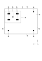
- FIG. 2 is a diagram showing an example of the work W processed by the laser processing device 1.
- the laser processing device 1 further performs laser processing on the workpiece W that has been processed (previously processed) by another processing device such as a press machine.
- the workpiece W is, for example, a rectangular plate as a whole, and has a plane portion Wa and end portions We corresponding to four sides.
- the workpiece W is formed with a hole portion Wc and a reference hole Wh which are formed by another processing device.
- the hole Wc is provided in a portion of the work W corresponding to the product M cut out by the laser processing apparatus 1 .
- the hole Wc may have a shape penetrating the front and back of the work W in the thickness direction, or may have a concave shape having a bottom.
- Three reference holes Wh that are circular in plan view (when viewed in the Z direction) are formed so that the workpiece position determination device 40 can determine the deviation of the workpiece W from the reference position. Further, there may be a case where the reference hole Wh is not formed because the ratio of the product M to the work W is large and a margin cannot be secured. In such a case, as will be described later, a mode is adopted in which the end portion We of the workpiece W is detected as the boundary portion Wb.
- a reference hole Wh unrelated to the product M is used for determining the deviation of the work W, but the present invention is not limited to this form.
- the hole Wc necessary for the product M may be used as the reference hole Wh for determining the deviation of the work W.
- the three reference holes Wh are arranged in the vicinity of three of the four corners of the workpiece W having a rectangular shape. By arranging the three reference holes Wh in this manner, the distance between the reference holes Wh can be increased, and the position of the workpiece W can be accurately determined.
- the reference hole Wh is not limited to being circular, and may be polygonal, elliptical, oval, or the like.
- the reference hole Wh may have a shape penetrating the front and back of the work W in the thickness direction, or may have a concave shape having a bottom. That is, the shape of the reference hole Wh is arbitrary as long as the appearance of the reference hole Wh is different from that of the plane portion Wa when the imaging unit 30 captures an image of the plane portion Wa, and the boundary portion Wb can be identified in the image captured by the imaging unit 30. is.
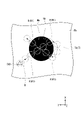
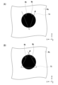
- FIG. 3 is a diagram showing an example of the relationship between the reference hole Wh and the observation range R of the imaging section 30.
- the control unit 41 causes the image capturing unit 30 to capture an image of the reference hole Wh provided in the workpiece W, and passes through a plurality of locations of the boundary portion Wb, which is the inner peripheral edge of the reference hole Wh in plan view.
- the head driving section 20 is controlled to move along a specified trajectory TA (hereinafter, the specified trajectory TA and the like may be collectively referred to as a specified trajectory T).
- the imaging unit 30 can acquire an observation range (image acquisition range) R as one image.
- the observation range R is an imaging range acquired by the imaging unit 30 in one imaging.
- the observation range R moves together with the imaging unit 30 as the imaging unit 30 moves along the prescribed trajectory TA.
- the prescribed trajectory TA is a trajectory set in advance so that the observation range R of the imaging section 30 passes through a plurality of locations on the boundary portion Wb of the plane portion Wa.
- the observation range R is set to be smaller than the reference hole Wh.
- the prescribed trajectory TA is pre-stored in the storage unit 42 .
- the prescribed trajectory TA is set according to the shape and dimensions of the reference hole Wh.
- the control unit 41 reads out the prescribed trajectory TA stored in the storage unit 42, controls the head driving unit 20 so that the observation range R moves along this trajectory TA, and causes the imaging unit 30 (head main body) to move. 11) is moved.
- the control unit 41 obtains the estimated position information and shape information of the reference hole Wh in the work W from the processing device or the like that processed the processed portion of the work W.
- the presumed position information of the reference hole Wh obtained in advance is only information regarding the presumed position of the reference hole Wh when the workpiece W is placed on the reference position S (see FIG. 12) without deviation.
- the control unit 41 sets a starting point (for example, coordinate values of X and Y) TA0 for starting the prescribed trajectory TA. 3 and 4, the starting point TA0 is indicated by a triangle.
- the control unit 41 moves the imaging unit 30 to the starting point TA0, and moves the imaging unit 30 from this starting point TA0 along the prescribed trajectory TA.
- the specified trajectory TA is a so-called unicursal trajectory that traverses the reference hole Wh from a starting point TA0 in plan view, then moves the plane portion Wa, and traverses the reference hole Wh again from a different position.
- It is the route of The imaging unit 30 performs imaging at a predetermined frame rate while moving along a prescribed trajectory TA. That is, the imaging unit 30 continuously acquires a plurality of images along the prescribed trajectory TA.
- the frame rate is set in advance according to the moving speed of the imaging unit 30 and the like.
- Information (image information) about a plurality of images captured by the imaging unit 30 is stored in the storage unit 42 .
- the control unit 41 acquires information (coordinate information) about the coordinate values of the imaging unit 30 (observation range R) at the time of capturing the image, associates the coordinate information with the image information, and stores the coordinate information in the storage unit 42 .
- the control unit 41 may acquire, for example, the position (X, Y coordinate values) of the laser head 10 at the timing of imaging from the head driving unit 20 or the like. It may be acquired from the output of a distance sensor or the like (not shown) that measures the position.
- each piece of image information is stored in association with the coordinate information of the imaging unit 30 (laser head 10) at the timing at which the image was captured.
- the observation range R at a position including the boundary portion Wb can be estimated from the pre-acquired estimated position information and shape information of the reference hole Wh.
- the control unit 41 may store the image estimated to be the image at the position including the boundary portion Wb in the storage unit 42 as a specific image, distinguishing it from other images, for example. Note that in FIGS. 3 and 4, the observation range R estimated to capture the specific image is indicated as an observation range R1.
- the control unit 41 acquires a plurality of pieces of image information and coordinate information through the above processing for each of the three reference holes Wh, and stores them in the storage unit 42 .
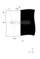
- FIG. 4 is a diagram showing an example of the relationship between the edge We and the observation range R of the imaging unit 30.
- the control unit 41 captures an image of an end We corresponding to a side of the workpiece W viewed as a rectangle by the imaging unit 30, and at a plurality of locations of the end We, which are boundary portions Wb in a plan view.
- the head drive unit 20 is controlled so as to move along a prescribed trajectory TB passing through the .
- the imaging unit 30 can acquire the observation range R as one image.
- the specified trajectory TB is set in advance so that the observation range R of the imaging section 30 passes through a plurality of locations on the end We (boundary portion Wb).
- the specified trajectory TB is set according to the position of the end We of the work W. As shown in FIG.
- the control unit 41 reads out the specified trajectory TB stored in the storage unit 42 and moves the observation range R along this trajectory TB.
- the control unit 41 obtains the estimated position information of the end We of the work W. As shown in FIG.
- the control unit 41 sets a starting point (for example, coordinate values of X and Y) TB0 at which the prescribed trajectory TB starts based on the estimated position information of the target end We.
- the control unit 41 moves the imaging unit 30 to the starting point TB0, and moves the imaging unit 30 from this starting point TB0 along the prescribed trajectory TB.
- the prescribed trajectory TB is a path that moves linearly in the -Y direction from the starting point TB0.
- the imaging unit 30 captures a plurality of images at a predetermined frame rate while moving along a prescribed trajectory TB.
- Information (image information) about a plurality of images captured by the imaging unit 30 is stored in the storage unit 42, and coordinate information at the time of image capturing is stored in the storage unit 42 in association with the image information. It is the same.
- the control unit 41 acquires a plurality of pieces of image information and coordinate information by the above processing for two different end portions We in the X direction and one end portion We in the Y direction, and stores them in the storage unit. Store in 42.
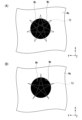
- 5 to 7 are diagrams showing examples of prescribed trajectories T set for the reference hole Wh.
- the specified trajectory T1 is set in the shape of a five-pointed star (five-pointed star, pentagonal star) in plan view, and passes through a plurality of locations on the boundary portion Wb.
- the specified trajectory T1 is a so-called one-stroke path.
- the size of the five-pointed star shape is set according to the size of the reference hole Wh obtained in advance.
- the imaging unit 30 performs imaging while moving the observation range R along a prescribed trajectory T1 in the shape of a five-pointed star in plan view.
- FIG. 5B it is possible to acquire specific images including the boundary portions Wb in ten observation ranges R1 from among the plurality of captured images.
- the prescribed locus T may be other than the pentagram-shaped prescribed locus T1.
- the prescribed trajectory T2 may be set in the shape of a seven-pointed star (a seven-pointed star, a heptagonal star) in plan view. This prescribed trajectory T2 also passes through a plurality of locations on the boundary portion Wb. Further, the prescribed locus T2 is a so-called one-stroke path.
- a prescribed trajectory T3 in which at least one line segment is, for example, curved in the shape of a five-pointed star may be used.
- the prescribed trajectory T is not limited to a pointed star shape, and may be any other shape as long as it passes through a plurality of locations on the boundary portion Wb.
- it may be a V-shaped prescribed trajectory T4, or as shown in FIG. 7B, it may be a triangular prescribed trajectory T5.
- the control section 41 may control the head drive section 20 so that the imaging section 30 moves along the prescribed trajectories T1 to T5 that draw a prescribed point-symmetrical shape or line-symmetrical shape.
- the imaging unit 30 By moving the imaging unit 30 along the specified trajectories T1 to T5 that draw a point-symmetrical shape or a line-symmetrical shape, it is possible to efficiently acquire image information at a plurality of locations on the inner peripheral edge of the reference hole Wh. Furthermore, by imaging the boundary portion Wb from a plurality of directions, the robustness of the determination accuracy by the position determination unit 43 can be improved.
- FIGS. 8A to 8C are diagrams showing an example of the prescribed trajectory T set for the end We of the work W.
- the specified trajectory T6 may be a linear zigzag shape that folds over the edge We, which is the boundary portion Wb.
- the specified trajectory T7 may have a wave shape (continuous sine curve shape) that changes so as to straddle the end portion We.
- the specified trajectory T8 may have a spiral shape along the end We.
- the spiral shape in the prescribed trajectory T8 corresponds to, for example, a shape in which the spiral shape as a three-dimensional shape is tilted and orthographically projected along the end portion We.
- the imaging unit 30 performs imaging while moving the observation range R along prescribed trajectories T6 to T8. As a result, it is possible to acquire a specific image including the boundary portion Wb at a plurality of locations among a plurality of captured images.
- the optical axis 63a of the irradiation optical system 61 that irradiates the laser beam L1 and the optical axis 34a of the imaging optical system 31 of the imaging unit 30 are coaxial.
- 9 and 10 are diagrams showing other examples of the imaging unit 30.
- the optical axis 63a of the irradiation optical system 61 and the optical axis 34a of the imaging optical system 31 may be different axes.
- the imaging section 30 may be provided in a state of being externally attached to the head main body 11 of the laser head 10 . In this case, the width W of the optical axis 63a and the optical axis 34a are offset.
- the control unit 41 acquires the coordinate information of the laser head 10 by the head driving unit 20 for each image captured by the imaging unit 30, and then associates the coordinate information obtained by offsetting the width W from this coordinate information with each image. Is required.
- the control unit 41 does not need to perform processing after obtaining the coordinate information of the laser head 10. You can reduce the burden. Further, there is no need for an offset error due to assembly accuracy or deformation after assembly, which occurs when the optical axis 63a and the optical axis 34a are not coaxial, and offset correction for eliminating this error. This offset correction is assumed to be frequently performed at the timing of starting the apparatus, and affects the machining efficiency. Therefore, by making the optical axis 63a and the optical axis 34a coaxial, the processing load on the control unit 41 after obtaining the coordinate information and the processing load at the time of device startup (preparation for processing) are reduced.
- the laser head 10 and the imaging unit 30 are arranged separately, the laser head 10 is moved by the head driving unit 20, and the imaging unit 30 is moved by the driving unit 80 separate from the head driving unit 20. It may be configured to be moved.
- the control unit 41 may control the driving unit 80 to move the imaging unit 30 and acquire coordinate information from the driving unit 80 when the imaging unit 30 captures the image.
- the single head driving unit 20 can be used both for moving the imaging unit 30 and for moving the laser head 10. can.
- a position determination unit 43 of the work position determination device 40 determines a position corresponding to the boundary portion Wb in the planar direction of the work W based on the image information and the coordinate information stored in the storage unit 42 .
- the position determination unit 43 determines the position of the center of the reference hole Wh in the work W based on the image information and the coordinate information of the reference hole Wh captured by the imaging unit 30. judge. In this case, the position determination unit 43 determines the position of the center of the reference hole Wh as the position corresponding to the boundary portion Wb.
- the position determination unit 43 does not have to determine the position itself of the boundary portion Wb captured by the imaging unit 30, but rather determines the predetermined position determined based on the position of the boundary portion Wb. may Further, when the edge We is used to determine the displacement of the work W, the position determination unit 43 determines the position of the edge We in the work W based on the image information and the coordinate information of the edge We captured by the imaging unit 30. judge. In this case, the position determination unit 43 determines the position of the end We as the position corresponding to the boundary Wb. That is, the position determination unit 43 may determine the position itself of the boundary portion Wb captured by the imaging unit 30 . The position determination unit 43 determines the position of the center or end We of the reference hole Wh using all the image information and position information captured by the imaging unit 30, for example.
- the position determination unit 43 may select image information to be used for position determination from a plurality of pieces of image information.
- Image information is selected by selecting image information with a high possibility of performing position determination (based on acquired image information or information from a separately provided sensor or the like) from the image information.
- image information that clearly includes the boundary portion Wb is processed, and image information that does not include the boundary portion Wb is rejected. This determination may be made from the image information alone, or may be made using other sensor information.
- the image information (the above-described specific image) estimated to include the boundary portion Wb is read from the storage unit 42, and the center of the reference hole Wh or the The position of the edge We may be determined.
- the position determination unit 43 may select image information by a different method. The position determination unit 43 first selects image information to be used for determining the position corresponding to the boundary portion Wb from among the plurality of image information captured by the imaging unit 30 . For example, the position determination unit 43 determines the brightness value of image information for each pixel, and determines that a boundary portion Wb exists when the difference in brightness value between a predetermined number of adjacent pixels exceeds a predetermined value, You can select the image.
- the position determination unit 43 can select image information using detection values of other sensors.
- a sensor for example, there is a sensor that determines whether or not there is a workpiece W directly below the laser head 10 .
- FIG. 11 is a diagram showing an example of selecting image information used for determining the position corresponding to the boundary portion Wb from a plurality of pieces of image information in the position determination unit 43.
- the upper part of FIG. 11 shows the moving speed of the laser head 10 when the laser head 10 moves along the prescribed trajectory T.
- the middle part of FIG. 11 shows the detection results of the other sensors, and detects an ON value when the workpiece W exists directly below the laser head 10, and an OFF value when it does not exist.
- the lower part of FIG. 11 shows the determination result of the position determination unit 43.
- the horizontal axis indicates the passage of time.
- the position determination unit 43 detects that the moving speed of the laser head 10 exceeds 0 and that the workpiece W exists directly below the laser head 10.
- Image information captured during the period can be selected as a target to be used for determination.
- One image of exactly the same location is sufficient, but when the boundary portion Wb is included in the imaging range, a plurality of images can be obtained as much as possible even if images of almost the same position are obtained. preferably.
- the position determination unit 43 may set the moving speed of the laser head 10 to a predetermined value or higher when selecting image information. By selecting the image information in this manner, the amount of information for determining the position of the center or end We of the reference hole Wh can be reduced, the processing load of the position determination unit 43 can be reduced, and the position determination can be performed. The processing speed of the unit 43 can be increased.
- the position determination unit 43 determines the position of the center or edge We of the reference hole Wh based on the selected image information and coordinate information.
- the position determining unit 43 extracts the position of the boundary portion Wb from each of the selected image information and the coordinate information, for example, and estimates from the positions of the plurality of boundary portions Wb.
- the position (coordinate value) of its center is calculated.
- the center of the virtual circle is estimated from the positions of a plurality of (for example, three or more) boundary portions Wb, for example, using pre-obtained shape information (for example, radius) of the reference hole Wh. That is, the position determination unit 43 does not have to calculate the virtual circle itself.
- the position determination unit 43 may, for example, extract the position and shape of the boundary portion Wb from the selected image information and coordinate information, and calculate the center position (coordinate values) from the curvature of the boundary portion Wb. Further, when determining the position of the end We, the position determination unit 43 extracts the position of the boundary Wb from each of the selected image information and coordinate information, for example, and estimates from the positions of the plurality of boundary Wb. The position (coordinate value) of the end We is calculated.
- the position determination unit 43 determines the position of the center or one end We of one reference hole Wh from a plurality of pieces of image information and coordinate information, respectively, and averages the plurality of judgment results to form one reference hole Wh.
- the center of the hole Wh or the position of one end We may be calculated. In this case, among a plurality of determination results, the maximum value and the minimum value may be excluded and averaged.
- the position determination unit 43 determines the center of one reference hole Wh by another method such as a method of excluding any of the determination results by removing outliers using quartiles for a plurality of determination results. , or the position of one end We may be calculated.
- the position determination unit 43 arranges the values of the plurality of determination results in ascending order, and sets the preset first quartile, second quartile, and third quartile. Quarter 1 to 2 quartile, or 2 to 3 quartile, 1st quartile One of the values from the number to the third quartile is used as a plurality of determination results, and the others are excluded as outliers to calculate the center of one reference hole Wh or the position of one end We. good too.
- the position determination unit 43 determines the positions of the centers P1, P2, and P3 of the three reference holes Wh1, Wh2, and Wh3 (see FIG. 12) on the workpiece W from their respective boundary portions Wb, for example.
- the positions of the centers P1, P2 and P3 are X and Y coordinate values.
- the position determination unit 43 determines the positions of three determination points P4, P5, and P6 (see FIG. 12) of the end We on the workpiece W, for example.
- the positions of the determination points P4, P5, and P6 are X and Y coordinate values.
- the deviation determination unit 44 determines the deviation of the workpiece W from the reference position S based on the determination result of the position corresponding to the boundary portion Wb by the position determination unit 43 . For example, the deviation determination unit 44 determines the position of the workpiece W with respect to the reference position S from the positions of the centers P1, P2, and P3 of the three reference holes Wh1, Wh2, and Wh3, which are the determination results of the positions corresponding to the three boundary portions Wb. Determine deviation. Further, the deviation determination unit 44 determines the deviation of the work W from the reference position S from the positions of three determination points P4, P5, and P6 on the edge We, for example.
- the determination points P4 and P5 are set on the portion of the end We along the first direction D1, and the determination point P6 is set on the portion of the end We along the second direction D2.
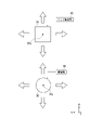
- the displacement of the workpiece W is determined by at least the amount of shift in each of the orthogonal first direction D1 (X direction) and the second direction D2 (Y direction), and the third direction D3 ( Z direction) and the amount of rotation (inclination) around the axis.
- the amount of shift of the work W relative to the reference position S in the first direction D1 and the second direction D2 and the amount of rotation about the axis in the third direction D3 are determined from the three reference holes Wh1, Wh2, and Wh3.
- the shift determination unit 44 may determine the shift amount in each of the orthogonal first direction D1 and second direction D2 with respect to the reference position S from the determination result of the position of at least one boundary portion Wb.
- the deviation determining section 44 may determine the deviation of the work W from one reference hole Wh.
- the position determination unit 43 first determines the position of the center P from the boundary portion Wb of one reference hole Wh. Subsequently, based on the determination result of the position determination unit 43, the shift determination unit 44 calculates only the shift amounts of the work W with respect to the reference position S in the first direction D1 and the second direction D2.
- the deviation determination unit 44 determines the first direction D1 and the second direction D2 of the work W with respect to the reference position S.
- a form in which only each shift amount is determined may be used.
- FIG. 12 is a diagram showing an example in which the workpiece W is arranged at the reference position S.
- FIG. 12 when the workpiece W is placed in alignment with the reference position S, of the four corners of the workpiece W, the -X side and -Y side corners coincide with the origin Wo, and the edge The portion We extends along the first direction D1 (X direction) and the second direction D2.
- the workpiece W is formed with three reference holes Wh1, Wh2, and Wh3.
- the coordinate values (X, Y) of the center P10 of the reference hole Wh1 when the work W is placed in alignment with the reference position S are (X1, Y1).
- the center P20 of the reference hole Wh2 has coordinate values (X1, Y2).
- the center P30 of the reference hole Wh3 has coordinate values (X2, Y1).
- the coordinate values of the determination point P40 of the end portion We when the work W is placed in alignment with the reference position S are (X3, 0).
- the determination point P50 of the edge We has coordinate values (X2, 0).
- the determination point P60 of the edge We has coordinate values (0, Y3).
- the control unit 41 acquires in advance the coordinate values of the centers P10, P20, and P30 at the reference position S and the coordinate values of the determination points P40, P50, and P60, and stores them in the storage unit .
- FIG. 13 is a diagram showing an example of the determination result of the deviation determination unit 44.
- the reference position S of the workpiece W is indicated by a dashed line.
- the positions of the centers P1, P2, and P3 of the reference holes Wh1, Wh2, and Wh3 determined by the position determination unit 43 are different from the above-described reference positions.
- the positions of the determination points P4, P5, and P6 determined by the position determining unit 43 are also determined from the coordinate values of the determination points P40, P50, and P60 in the reference position S described above in the first direction D1 (X direction) and the second direction D1. It is shifted in the direction D2 (Y direction) and rotated around the axis in the third direction D3 (Z direction). As a result, as shown in FIG. 13, the position of the origin Wo is shifted to the position of the origin Wo'.
- the deviation determination unit 44 determines the coordinate values of the at least three centers P1, P2, and P3 (six values in total) determined by the position determination unit 43, or the coordinate values of the determination points P4, P5, and P6 (six values in total). , the amount of shift in the first direction D1 and the second direction D2, and the amount of rotation (inclination) about the axis in the third direction D3 orthogonal to the first direction D1 and the second direction D2.
- the shift determination unit 44 uses three determination parameters, the amount of shift in the first direction D1 and the second direction D2, and the amount of rotation about the axis in the third direction D3. ), the two amounts of shift and rotation can be reliably calculated.
- the deviation determination unit 44 makes three determinations of the two shift amounts and the rotation amount, as well as the expansion and contraction amount (X scale) of the workpiece W in the first direction D1 (X direction). ), the expansion/contraction amount (Y scale) of the workpiece W in the second direction D2 (X direction), and the orthogonality between the first direction D1 and the second direction D2 can be determined.
- the control unit 41 controls the head driving unit 20 so as to move the laser head 10 in accordance with the deviation. For example, the control unit 41 corrects the coordinates related to the placement of the workpiece W during laser processing according to the deviation from the reference position S.
- the control unit 41 may change the target coordinate values for the laser head 10 according to the shift in the machining program including the information about the movement of the laser head 10, and execute the machining program as the new coordinate values.
- FIG. 14 is a flow chart showing an example of a workpiece position determination method according to the embodiment.
- the controller 41 first moves the laser head 10 to an estimated position in the observation range (step S01).
- the control unit 41 moves the laser head 10 to, for example, the vicinity of the reference hole Wh or the end We as the estimated position of the observation range based on the pre-obtained estimated position information of the reference hole Wh or the end We.
- the head driving section 20 is controlled as follows.
- the control unit 41 sets imaging conditions for the imaging unit 30 (step S02).
- the control unit 41 sets imaging conditions such as a focal position and exposure in the imaging optical system 31 of the imaging unit 30 . Further, the control unit 41 performs control so that the illumination laser light L2 is emitted from the laser array 70 via the illumination optical system 71 when the imaging unit 30 takes an image.
- the control unit 41 causes the imaging unit 30 to image the estimated position of the observation range to obtain image information, and causes the image information to be transmitted to the workpiece position determination device 40 (step S03).
- the image information imaged in step S03 is used for evaluation of imaging conditions.
- the image information in step S03 may be one or plural.
- the control unit 41 receives the image information transmitted from the imaging unit 30 (step S04), and evaluates the imaging conditions based on the received image information (step S05). For example, evaluation image information for evaluating imaging conditions is stored in the storage unit 42, and the control unit 41 compares the received image information with the evaluation image information stored in the storage unit 42. , defocus (bokeh), exposure, and other shooting conditions may be evaluated. Subsequently, the control unit 41 transmits the evaluation result to the imaging unit 30 (step S06). The imaging unit 30 receives the transmitted evaluation result (step S07), and adjusts the imaging conditions based on the evaluation result (step S08). Steps S03 to S08 may be performed only once at the beginning, or may be performed repeatedly several times, for example, by feedback control of focus and luminance.
- the imaging unit 30 acquires image information while moving along the prescribed trajectory T, and further acquires coordinate information of the imaging unit 30 when the image information was captured (step S09).
- the control unit 41 moves the imaging unit 30 to the starting points TA0, TB0 (see FIGS. 3 and 4).
- the imaging unit 30 is controlled to perform imaging at a predetermined frame rate while moving from TB0 along prescribed trajectories TA and TB.
- the imaging unit 30 moves from starting points TA0 and TB0 along prescribed trajectories TA and TB, acquires image information by imaging the reference hole Wh or the boundary portion Wb of the end portion We, and acquires image information at the imaging position where the image information is imaged. acquires the coordinate information of and associates it with the image information.
- the imaging unit 30 captures an image while acquiring the coordinate information of the laser head 10 from the head drive unit 20, and associates the coordinate information of the laser head 10 acquired at the timing of imaging with the image information. Further, as described above, when the position determination unit 43 uses information from other sensors and speed information of the laser head 10 for position determination, these information are also added to the image information captured by the image capturing unit 30 at the same time as the image capturing. (or at a predetermined timing after imaging). Note that step S09 is performed for each of a plurality of reference holes Wh or a plurality of end portions We. Subsequently, the imaging unit 30 transmits the acquired image information and coordinate information to the workpiece position determination device 40 (step S10).
- the image pickup unit 30 collectively transmits a plurality of image information and position information picked up while moving the specified trajectory T to the work position determination device 40 .
- the image pickup unit 30 collectively transmits a plurality of pieces of image information and position information by the imaging unit 30 in this way, the time required for transmission processing can be shortened.
- control unit 41 receives the transmitted image information and coordinate information (step S11), and causes the storage unit 42 to store them.
- the position determination unit 43 determines the position of the boundary portion Wb based on the image information and coordinate information stored in the storage unit 42 (step S12).
- the position determination unit 43 determines, for example, the position (coordinate value) of the center calculated from the boundary portion Wb of the reference hole Wh, or the position (coordinate value) of the end portion We, which is the boundary portion Wb.
- the deviation determination unit 44 determines the deviation of the work W based on the determination result of the position determination unit 43 (step S13). For example, the deviation determination unit 44 determines the deviation of the workpiece W from the reference position S from the positions of the centers of the at least three reference holes Wh or from the positions of the at least three ends We. The amount of shift in each of the D1 and second directions D2 and the amount of rotation about the axis in the third direction D3 are determined. In steps S09 to S13, the deviation of the workpiece W from the reference position S may be determined from the center position of one reference hole Wh. In this case, in step S09, the imaging unit 30 images one reference hole Wh.
- step S12 the position determination unit 43 determines the position of the center P from the boundary portion Wb of one reference hole Wh.
- the displacement determination unit 44 calculates only the shift amounts of the work W with respect to the reference position S in the first direction D1 and the second direction D2.
- the shift of the workpiece W may be determined using one reference hole Wh.
- the control unit 41 transmits the determination result of the deviation determination unit 44 to the laser head 10 (step S14).
- the laser head 10 receives the transmitted determination result (step S15), and based on the received determination result, the coordinates of the workpiece W during laser processing are corrected (step S16).
- the communication between the laser head 10, the imaging unit 30, and the work position determination device 40 is transmission/reception from step S10 to step S11, and transmission/reception from step S14 to step S15.
- no communication is performed between the laser head 10, the imaging unit 30, and the workpiece position determining device 40 during steps S11 to S14.
- the laser head 10 can accurately perform laser processing on the workpiece W by moving according to the corrected coordinates. A series of processing ends when step S16 is completed.
- the imaging unit 30 is moved along the prescribed trajectory T in plan view, and the image information captured by the imaging unit 30 during this movement and the Since the displacement of the work W with respect to the reference position S is determined based on the coordinate information, feedback control of the head driving section 20 is not required for movement of the imaging section 30 . Therefore, there is no need to consider delays in image processing calculations and delays in communication such as movement commands with respect to the movement of the imaging unit 30, so the time required to determine the displacement of the workpiece W can be shortened. Further, in the laser processing apparatus 1 including the work position determining device 40, the time required for determining the shift of the work W is shortened, so the processing efficiency of the work W can be improved.
Landscapes
- Engineering & Computer Science (AREA)
- Physics & Mathematics (AREA)
- Optics & Photonics (AREA)
- Mechanical Engineering (AREA)
- Plasma & Fusion (AREA)
- Human Computer Interaction (AREA)
- Manufacturing & Machinery (AREA)
- General Physics & Mathematics (AREA)
- Automation & Control Theory (AREA)
- Laser Beam Processing (AREA)
- Numerical Control (AREA)
- Machine Tool Sensing Apparatuses (AREA)
Abstract
Description
TB0から規定の軌跡TA、TBに沿って移動させつつ、所定のフレームレートで撮像を行うように撮像部30を制御する。撮像部30は、始点TA0、TB0から規定の軌跡TA、TBに沿って移動し、基準穴Wh又は端部Weの境界部分Wbを撮像して画像情報を取得し、画像情報を撮像した撮像位置の座標情報を取得して画像情報に対応付ける。
D2・・・第2方向
D3・・・第3方向
P1、P2、P3・・・中心
R、R1・・・観察範囲
T、TA、TB、T1、T2、T3、T4、T5、T6、T7・・・軌跡
W・・・ワーク
Wa・・・平面部
Wb・・・境界部分
Wc・・・穴部
We・・・端部
Wh、Wh1、Wh2、Wh3・・・基準穴
Wo・・・原点
1・・・レーザ加工装置
10・・・レーザヘッド
20・・・ヘッド駆動部(駆動部)
30・・・撮像部
34a、63a、72a・・・光軸
40・・・ワーク位置判定装置
41・・・制御部
42・・・記憶部
43・・・位置判定部
44・・・ずれ判定部
80・・・駆動部
100・・・加工部
Claims (12)
- 撮像部と、
平面部を有するワークに対し、前記撮像部を前記平面部と平行な平面方向に相対的に移動させる駆動部と、
前記撮像部が、平面視において前記平面部における境界部分の複数個所を通過する規定の軌跡で移動するように前記駆動部を制御する制御部と、
前記撮像部が前記規定の軌跡で移動する間に当該撮像部により撮像された画像情報、及び各画像情報を撮影した際の前記撮像部の座標情報を記憶する記憶部と、
前記記憶部に記憶された前記画像情報及び前記座標情報に基づいて、前記ワークの前記平面方向における前記境界部分に対応する位置を判定する位置判定部と、
前記位置判定部による判定結果に基づいて、基準位置に対する前記ワークのずれを判定するずれ判定部と、を備えるワーク位置判定装置。 - 前記撮像部における撮像光学系は、前記ワークにレーザ光を照射することにより当該ワークを加工するレーザ加工装置の加工部における前記レーザ光の照射光学系と同軸に設けられる、請求項1に記載のワーク位置判定装置。
- 前記制御部は、前記撮像部が前記ワークに設けられた基準穴を撮像しつつ平面視において当該基準穴の内周縁の複数個所を通過する規定の軌跡で移動するように前記駆動部を制御し、
前記位置判定部は、前記ワークにおける前記基準穴の中心の位置を算出する、請求項1又は請求項2に記載のワーク位置判定装置。 - 前記制御部は、平面視において前記撮像部が規定の点対称形状又は線対称形状を描く軌跡で移動するように前記駆動部を制御する、請求項3に記載のワーク位置判定装置。
- 前記撮像部により撮像される一画像の観察範囲は、前記基準穴より小さい、請求項3又は請求項4に記載のワーク位置判定装置。
- 前記制御部は、前記撮像部が前記ワークの辺に相当する端部を撮像しつつ平面視において当該端部の複数個所を通過する規定の軌跡で移動するように前記駆動部を制御し、
前記位置判定部は、前記ワークにおける前記端部の位置を判定する、請求項1又は請求項2に記載のワーク位置判定装置。 - 前記制御部は、平面視において前記撮像部が規定の直線状、曲線状、ジグザグ状、又はスパイラル状を描く軌跡で移動するように前記駆動部を制御する、請求項6に記載のワーク位置判定装置。
- 前記位置判定部は、前記撮像部により撮像された複数の前記画像情報のうち、前記境界部分の位置の判定に用いる前記画像情報を選択し、選択した前記画像情報に対応する前記座標情報に基づいて、前記境界部分の位置を判定する請求項1から請求項7のいずれか一項に記載のワーク位置判定装置。
- 前記ずれ判定部は、少なくとも1箇所の前記境界部分の位置の判定結果から、前記基準位置に対する、直交する第1方向及び第2方向それぞれのシフト量を判定する、請求項1から請求項8のいずれか一項に記載のワーク位置判定装置。
- 前記ずれ判定部は、少なくとも3個所の前記境界部分の位置の判定結果から、前記基準位置に対する、直交する第1方向及び第2方向それぞれのシフト量、及び前記第1方向及び前記第2方向と直交する第3方向の軸まわりの回転量を判定する、請求項9に記載のワーク位置判定装置。
- 平面部を有するワークにレーザ光を照射することにより当該ワークを加工する加工部を備えるレーザ加工装置であって、
請求項1から請求項10のいずれか一項に記載のワーク位置判定装置を備えるレーザ加工装置。 - 平面部を有するワークに対し、前記平面部と平行な平面方向であってかつ平面視において前記平面部における境界部分の複数個所を通過する規定の軌跡で撮像部を相対的に移動させることと、
前記撮像部が前記規定の軌跡で移動する間に当該撮像部により撮像された画像情報、及び各画像情報を撮影した際の前記撮像部の座標情報を記憶することと、
記憶された前記画像情報及び前記座標情報に基づいて、前記ワークの前記平面方向における前記境界部分に対応する位置を判定することと、
前記境界部分に対応する位置の判定結果に基づいて、基準位置に対する前記ワークのずれを判定することと、を含むワーク位置判定方法。
Priority Applications (4)
| Application Number | Priority Date | Filing Date | Title |
|---|---|---|---|
| EP22872635.2A EP4406685A4 (en) | 2021-09-24 | 2022-08-24 | WORKPIECE LOCATION DETERMINING DEVICE, LASER PROCESSING DEVICE, AND WORKPIECE LOCATION DETERMINING METHOD |
| CN202280061562.XA CN117940246A (zh) | 2021-09-24 | 2022-08-24 | 工件位置判定装置、激光加工装置以及工件位置判定方法 |
| KR1020247009454A KR20240045331A (ko) | 2021-09-24 | 2022-08-24 | 가공물 위치 판정 장치, 레이저 가공 장치, 및 가공물 위치 판정 방법 |
| US18/692,382 US20240383089A1 (en) | 2021-09-24 | 2022-08-24 | Workpiece position determination device, laser machining device, and workpiece position determination method |
Applications Claiming Priority (2)
| Application Number | Priority Date | Filing Date | Title |
|---|---|---|---|
| JP2021-156087 | 2021-09-24 | ||
| JP2021156087A JP7582145B2 (ja) | 2021-09-24 | 2021-09-24 | ワーク位置判定装置、レーザ加工装置、及びワーク位置判定方法 |
Publications (1)
| Publication Number | Publication Date |
|---|---|
| WO2023047879A1 true WO2023047879A1 (ja) | 2023-03-30 |
Family
ID=85720534
Family Applications (1)
| Application Number | Title | Priority Date | Filing Date |
|---|---|---|---|
| PCT/JP2022/031947 Ceased WO2023047879A1 (ja) | 2021-09-24 | 2022-08-24 | ワーク位置判定装置、レーザ加工装置、及びワーク位置判定方法 |
Country Status (6)
| Country | Link |
|---|---|
| US (1) | US20240383089A1 (ja) |
| EP (1) | EP4406685A4 (ja) |
| JP (1) | JP7582145B2 (ja) |
| KR (1) | KR20240045331A (ja) |
| CN (1) | CN117940246A (ja) |
| WO (1) | WO2023047879A1 (ja) |
Families Citing this family (1)
| Publication number | Priority date | Publication date | Assignee | Title |
|---|---|---|---|---|
| CN118559663B (zh) * | 2024-08-05 | 2024-10-29 | 深圳市新凯来工业机器有限公司 | 对准装置及对准方法 |
Citations (7)
| Publication number | Priority date | Publication date | Assignee | Title |
|---|---|---|---|---|
| JPH09502553A (ja) * | 1993-09-11 | 1997-03-11 | プッツマイスター・ヴェルク マシーネンファブリーク ゲゼルシャフト ミット ベシュレンクテル ハフツング | 少なくとも1つの処理ユニットを有する処理装置により対象物を処理する方法 |
| JP3660041B2 (ja) | 1996-01-17 | 2005-06-15 | 株式会社アマダ | レーザ加工機におけるワーク位置検出方法及び装置 |
| JP2008076200A (ja) * | 2006-09-21 | 2008-04-03 | Soatec Inc | 光学式測定システム |
| JP6253847B1 (ja) * | 2016-11-28 | 2017-12-27 | 三菱電機株式会社 | レーザ加工装置、レーザ加工方法、及びレーザ加工プログラム |
| WO2021109575A1 (zh) * | 2019-12-02 | 2021-06-10 | 广东技术师范大学 | 基于融入全局视觉和局部视觉的机器人视觉引导方法和装置 |
| JP6905651B1 (ja) * | 2019-12-13 | 2021-07-21 | 川崎重工業株式会社 | ロボットシステム及びワークの3次元モデルの形成方法 |
| JP2021156087A (ja) | 2020-03-30 | 2021-10-07 | 大和ハウス工業株式会社 | 布基礎 |
Family Cites Families (8)
| Publication number | Priority date | Publication date | Assignee | Title |
|---|---|---|---|---|
| JP3855684B2 (ja) * | 2001-06-05 | 2006-12-13 | 松下電器産業株式会社 | レーザ加工装置およびレーザ加工方法 |
| JP2008221299A (ja) * | 2007-03-14 | 2008-09-25 | Hitachi Via Mechanics Ltd | レーザ加工装置 |
| JP5374909B2 (ja) * | 2008-04-10 | 2013-12-25 | 株式会社Ihi | マーキング装置 |
| EP2937753B1 (de) * | 2014-04-24 | 2019-07-31 | Siemens Aktiengesellschaft | Verfahren zum Vermessen von Werkstücken und nach dem Verfahren arbeitende Produktions- und/oder Werkzeugmaschine |
| JP6464213B2 (ja) * | 2017-02-09 | 2019-02-06 | ファナック株式会社 | レーザ加工ヘッドおよび撮影装置を備えるレーザ加工システム |
| JP2019115923A (ja) * | 2017-12-27 | 2019-07-18 | 三菱重工工作機械株式会社 | 芯出し装置、レーザ加工機、レーザ加工機の芯出し方法、およびプログラム |
| JP7405606B2 (ja) * | 2019-12-26 | 2023-12-26 | 株式会社キーエンス | レーザ加工装置 |
| JP7417503B2 (ja) * | 2020-09-25 | 2024-01-18 | 芝浦機械株式会社 | 加工機、計測装置及び被加工物の製造方法 |
-
2021
- 2021-09-24 JP JP2021156087A patent/JP7582145B2/ja active Active
-
2022
- 2022-08-24 KR KR1020247009454A patent/KR20240045331A/ko active Pending
- 2022-08-24 CN CN202280061562.XA patent/CN117940246A/zh active Pending
- 2022-08-24 WO PCT/JP2022/031947 patent/WO2023047879A1/ja not_active Ceased
- 2022-08-24 EP EP22872635.2A patent/EP4406685A4/en not_active Withdrawn
- 2022-08-24 US US18/692,382 patent/US20240383089A1/en active Pending
Patent Citations (7)
| Publication number | Priority date | Publication date | Assignee | Title |
|---|---|---|---|---|
| JPH09502553A (ja) * | 1993-09-11 | 1997-03-11 | プッツマイスター・ヴェルク マシーネンファブリーク ゲゼルシャフト ミット ベシュレンクテル ハフツング | 少なくとも1つの処理ユニットを有する処理装置により対象物を処理する方法 |
| JP3660041B2 (ja) | 1996-01-17 | 2005-06-15 | 株式会社アマダ | レーザ加工機におけるワーク位置検出方法及び装置 |
| JP2008076200A (ja) * | 2006-09-21 | 2008-04-03 | Soatec Inc | 光学式測定システム |
| JP6253847B1 (ja) * | 2016-11-28 | 2017-12-27 | 三菱電機株式会社 | レーザ加工装置、レーザ加工方法、及びレーザ加工プログラム |
| WO2021109575A1 (zh) * | 2019-12-02 | 2021-06-10 | 广东技术师范大学 | 基于融入全局视觉和局部视觉的机器人视觉引导方法和装置 |
| JP6905651B1 (ja) * | 2019-12-13 | 2021-07-21 | 川崎重工業株式会社 | ロボットシステム及びワークの3次元モデルの形成方法 |
| JP2021156087A (ja) | 2020-03-30 | 2021-10-07 | 大和ハウス工業株式会社 | 布基礎 |
Non-Patent Citations (1)
| Title |
|---|
| See also references of EP4406685A4 |
Also Published As
| Publication number | Publication date |
|---|---|
| CN117940246A (zh) | 2024-04-26 |
| EP4406685A4 (en) | 2025-10-01 |
| EP4406685A1 (en) | 2024-07-31 |
| US20240383089A1 (en) | 2024-11-21 |
| JP2023047141A (ja) | 2023-04-05 |
| JP7582145B2 (ja) | 2024-11-13 |
| KR20240045331A (ko) | 2024-04-05 |
Similar Documents
| Publication | Publication Date | Title |
|---|---|---|
| US10092977B2 (en) | Welding head and method for joining a workpiece | |
| JP5931537B2 (ja) | レーザの光軸アライメント方法およびそれを用いたレーザ加工装置 | |
| EP2769800B1 (en) | Laser processing machine | |
| CN107803585B (zh) | 激光加工机及激光加工方法 | |
| US20170186656A1 (en) | Wafer processing method | |
| JP2009262163A (ja) | アライメント調整方法及び装置、及びそれを備えたレーザー加工装置 | |
| JP7375634B2 (ja) | レーザ加工システム、及びレーザ加工方法 | |
| JP6592547B2 (ja) | レーザ光の芯出し方法及びレーザ加工装置 | |
| JP7582145B2 (ja) | ワーク位置判定装置、レーザ加工装置、及びワーク位置判定方法 | |
| JP2004276101A (ja) | レーザ加工方法及びレーザ加工装置 | |
| JP7664524B2 (ja) | 亀裂検出装置及び亀裂検出装置の制御方法 | |
| JP5058624B2 (ja) | レーザ顕微鏡 | |
| WO2012023250A1 (ja) | 部品実装装置および部品検出方法 | |
| CN114127973B (zh) | 沉积机的基底定位 | |
| JP2025537365A (ja) | パッケージング用途のための表面下位置合わせ計測システム | |
| JP2002316276A (ja) | レーザマーキング装置のマーキング歪み補正装置及びマーキング補正方法 | |
| KR20130073050A (ko) | 레이저 가공 장치 및 그 보정 데이터 생성 방법 | |
| US20210060697A1 (en) | Method of determining whether or not result of processing process of laser processing apparatus is acceptable | |
| JP2000294608A (ja) | 表面画像投影装置及び方法 | |
| CN114096369A (zh) | 控制装置及具备控制装置的激光加工系统、激光加工方法 | |
| JP3063677B2 (ja) | レーザ加工装置及びレーザ加工方法 | |
| JP5205101B2 (ja) | パターン描画装置およびパターン描画方法 | |
| JP5142916B2 (ja) | レーザ加工方法、及び、レーザ加工装置 | |
| KR20190063027A (ko) | 라인 스캐닝 방식의 공초점 현미경에서의 자동초점조절 방법 및 장치 | |
| JP2003077141A (ja) | 光学ヘッド調整装置 |
Legal Events
| Date | Code | Title | Description |
|---|---|---|---|
| 121 | Ep: the epo has been informed by wipo that ep was designated in this application |
Ref document number: 22872635 Country of ref document: EP Kind code of ref document: A1 |
|
| WWE | Wipo information: entry into national phase |
Ref document number: 202280061562.X Country of ref document: CN |
|
| WWE | Wipo information: entry into national phase |
Ref document number: 18692382 Country of ref document: US |
|
| WWE | Wipo information: entry into national phase |
Ref document number: 2022872635 Country of ref document: EP |
|
| NENP | Non-entry into the national phase |
Ref country code: DE |
|
| ENP | Entry into the national phase |
Ref document number: 2022872635 Country of ref document: EP Effective date: 20240424 |
|
| WWW | Wipo information: withdrawn in national office |
Ref document number: 2022872635 Country of ref document: EP |