WO2023047885A1 - 作業機械の制御システムおよび作業機械 - Google Patents
作業機械の制御システムおよび作業機械 Download PDFInfo
- Publication number
- WO2023047885A1 WO2023047885A1 PCT/JP2022/032212 JP2022032212W WO2023047885A1 WO 2023047885 A1 WO2023047885 A1 WO 2023047885A1 JP 2022032212 W JP2022032212 W JP 2022032212W WO 2023047885 A1 WO2023047885 A1 WO 2023047885A1
- Authority
- WO
- WIPO (PCT)
- Prior art keywords
- work machine
- work
- evacuation
- control system
- management unit
- Prior art date
- Legal status (The legal status is an assumption and is not a legal conclusion. Google has not performed a legal analysis and makes no representation as to the accuracy of the status listed.)
- Ceased
Links
Images




Classifications
-
- E—FIXED CONSTRUCTIONS
- E02—HYDRAULIC ENGINEERING; FOUNDATIONS; SOIL SHIFTING
- E02F—DREDGING; SOIL-SHIFTING
- E02F9/00—Component parts of dredgers or soil-shifting machines, not restricted to one of the kinds covered by groups E02F3/00 - E02F7/00
- E02F9/20—Drives; Control devices
- E02F9/2025—Particular purposes of control systems not otherwise provided for
-
- E—FIXED CONSTRUCTIONS
- E02—HYDRAULIC ENGINEERING; FOUNDATIONS; SOIL SHIFTING
- E02F—DREDGING; SOIL-SHIFTING
- E02F9/00—Component parts of dredgers or soil-shifting machines, not restricted to one of the kinds covered by groups E02F3/00 - E02F7/00
- E02F9/26—Indicating devices
- E02F9/267—Diagnosing or detecting failure of vehicles
- E02F9/268—Diagnosing or detecting failure of vehicles with failure correction follow-up actions
-
- E—FIXED CONSTRUCTIONS
- E02—HYDRAULIC ENGINEERING; FOUNDATIONS; SOIL SHIFTING
- E02F—DREDGING; SOIL-SHIFTING
- E02F9/00—Component parts of dredgers or soil-shifting machines, not restricted to one of the kinds covered by groups E02F3/00 - E02F7/00
- E02F9/20—Drives; Control devices
- E02F9/2025—Particular purposes of control systems not otherwise provided for
- E02F9/2045—Guiding machines along a predetermined path
-
- E—FIXED CONSTRUCTIONS
- E02—HYDRAULIC ENGINEERING; FOUNDATIONS; SOIL SHIFTING
- E02F—DREDGING; SOIL-SHIFTING
- E02F3/00—Dredgers; Soil-shifting machines
- E02F3/04—Dredgers; Soil-shifting machines mechanically-driven
- E02F3/28—Dredgers; Soil-shifting machines mechanically-driven with digging tools mounted on a dipper- or bucket-arm, i.e. there is either one arm or a pair of arms, e.g. dippers, buckets
- E02F3/36—Component parts
- E02F3/42—Drives for dippers, buckets, dipper-arms or bucket-arms
- E02F3/43—Control of dipper or bucket position; Control of sequence of drive operations
- E02F3/431—Control of dipper or bucket position; Control of sequence of drive operations for bucket-arms, front-end loaders, dumpers or the like
- E02F3/434—Control of dipper or bucket position; Control of sequence of drive operations for bucket-arms, front-end loaders, dumpers or the like providing automatic sequences of movements, e.g. automatic dumping or loading, automatic return-to-dig
-
- E—FIXED CONSTRUCTIONS
- E02—HYDRAULIC ENGINEERING; FOUNDATIONS; SOIL SHIFTING
- E02F—DREDGING; SOIL-SHIFTING
- E02F9/00—Component parts of dredgers or soil-shifting machines, not restricted to one of the kinds covered by groups E02F3/00 - E02F7/00
- E02F9/24—Safety devices, e.g. for preventing overload
-
- E—FIXED CONSTRUCTIONS
- E02—HYDRAULIC ENGINEERING; FOUNDATIONS; SOIL SHIFTING
- E02F—DREDGING; SOIL-SHIFTING
- E02F9/00—Component parts of dredgers or soil-shifting machines, not restricted to one of the kinds covered by groups E02F3/00 - E02F7/00
- E02F9/26—Indicating devices
- E02F9/261—Surveying the work-site to be treated
- E02F9/262—Surveying the work-site to be treated with follow-up actions to control the work tool, e.g. controller
-
- B—PERFORMING OPERATIONS; TRANSPORTING
- B60—VEHICLES IN GENERAL
- B60Y—INDEXING SCHEME RELATING TO ASPECTS CROSS-CUTTING VEHICLE TECHNOLOGY
- B60Y2200/00—Type of vehicle
- B60Y2200/40—Special vehicles
- B60Y2200/41—Construction vehicles, e.g. graders, excavators
- B60Y2200/415—Wheel loaders
Definitions
- the present invention relates to a work machine control system and a work machine.
- a work machine that automatically excavates an object to be excavated and loads it at a predetermined loading position and a control system for the work machine have been proposed. Since dump trucks and other work machines may enter the work site to carry in materials, it is required that the work machine that operates automatically avoids contact with them and continues work.
- Patent Document 1 when automatic driving cannot be switched to manual driving, the vehicle is evacuated to a preset evacuation location based on the route information set in the vehicle, and the driver can operate manually.
- a driving support technology has been disclosed that takes over driving after waiting for a change.
- Patent Document 2 discloses an automatic driving control device that automatically drives based on a road structure map, and when automatic driving cannot be controlled, the vehicle is evacuated to the road shoulder in the section where the wire rope type guard fence is installed.
- An automatic cruise control system is disclosed.
- Patent Documents 1 and 2 are intended for vehicles traveling on public roads, and are only considered for safe evacuation. However, when evacuating a work machine that travels while performing work within the work area, it is necessary to consider the traveling route and work efficiency of the dump truck and other work machines that work within the work area. In these cited documents, no consideration is given to the reduction in work efficiency due to travel paths and evacuation of dump trucks and other work machines working within the work area.
- a typical present invention is a control system for a work machine comprising a control device for operating the work machine, wherein the control device stores information about work to be performed by the work machine. and a current position of the work machine, and sets a target position based on the work instruction and the current position; and a target route between the current position and the target position. and a motion generator for causing the work machine to travel according to the target route, wherein the action management unit controls the evacuation based on the work range of a work machine different from the work machine.
- a retraction instruction including a position, determining a retraction position from among the retractable positions based on the work range of another work machine and the current position of the work machine when the retraction instruction is received;
- the retraction position is set to the target position.
- FIG. 1 is a configuration diagram of a control system for a wheel loader according to a first embodiment
- FIG. It is a hardware block diagram of the control system of 1st embodiment.
- (a) to (c) are explanatory diagrams for explaining map data of the first embodiment.
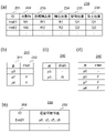
- (a) shows an example of a work instruction according to the first embodiment
- (b) to (d) show an example of a target route according to the first embodiment
- (e) shows an example of an evacuation instruction according to the first embodiment.
- the work machine 100 such as a wheel loader that automatically travels within the work area 300 repeats excavating an excavating target 310 and transporting the excavated target to a loading target 320 in accordance with work instructions.
- a transport vehicle 330 that operates differently from the work machine 100 enters there.
- the transport vehicle 330 is, for example, a dump truck or the like that transports the object loaded in the loading object 320 to the outside of the work area 300 or replenishes the excavating object 310 .
- a management device (computer provided in a management center) or the like that controls the entire work area may be provided.
- control system 180 when the transport vehicle 330 enters the work area 300, an evacuation instruction is transmitted to the control system 180 (see FIG. 3) of the work machine 100.
- control system 180 of work machine 100 receives a retraction instruction, control system 180 retracts to a retraction position that minimizes a decrease in work efficiency.
- the working machine 100 and its control system 180 that realize this will be described below.
- a wheel loader will be described as an example of the working machine 100 .
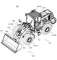
- FIG. 2 is a diagram schematically showing the appearance of the wheel loader 100 of this embodiment
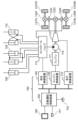
- FIG. 3 is a diagram showing a control system 180 of the wheel loader 100 of this embodiment.
- the wheel loader 100 includes a vehicle body 110 and an articulated working machine 120 attached to the front of the vehicle body 110 .
- the working machine 120 is a working device driven by at least one actuator.
- Work machine 120 shown in FIG. 2 includes bucket 121 , lift arm 122 , bell crank 123 , bucket link 124 , lift cylinder 125 , bucket cylinder 126 , and steering cylinder 112 .
- the bucket 121 is a working tool provided in front of the vehicle body.
- Lift cylinder 125 and bucket cylinder 126 are hydraulic actuators (hydraulic cylinders) that drive bucket 121 and lift arm 122 respectively, and are attached between work implement 120 and vehicle body 110 .
- One lift arm 122 and one lift cylinder 125 are provided on each of the left and right sides of the vehicle body 110 .
- the lift arm 122 is rotatably supported by the vehicle body 110, and rotates vertically (elevates) as the lift cylinder 125 is driven to extend and retract.
- the bucket 121 rotates (dump operation or tilt operation) as the bucket cylinder 126 is driven to extend and retract.
- the lift cylinder 125 has one end connected to the lift arm 122 and the other end connected to the vehicle body 110 .
- the bucket cylinder 126 has one end connected to the bell crank 123 and the other end connected to the vehicle body 110 .
- the link mechanism for operating the bucket 121 of the wheel loader 100 shown in FIG. 2 is of a Z-link type (bell crank type) using a bell crank 123.
- the vehicle body 110 is provided with four wheels (a front right tire 131FR, a front left tire 131FL, a rear right tire 131RR (see FIG. 2), and a rear left tire 131RL). Hereinafter, they are collectively referred to as tires 131 when there is no particular need to distinguish them.
- Each tire 131 is driven by a power transmission device using the engine 111 (see FIG. 3) as a power source.
- the wheel loader 100 moves forward or backward by transmitting driving force to the ground via each tire 131 .
- the wheel loader 100 has an articulated steering mechanism, and turns by creating an angle difference between the front and rear of the vehicle body about the vertical direction of the vehicle body.
- Wheel loader 100 as shown in FIG. A differential 134F, a rear differential 134R, a positioning device 141, a pressure sensor 142, a control system 180, and a user interface 190 are provided.
- control system 180 includes an automatic operation control device 200, a hydraulic control device 160, an engine control device 150, and a travel control device 170, as shown in FIG.
- the engine 111 is the power source of the wheel loader 100.
- Engine 111 drives hydraulic pump 114 and driving force transmission device 113 .
- the driving force transmission device 113 is transmitted to the front right tire 131FR and the front left tire 131FL via the center joint 132C and the front differential 134F, and to the rear right tire 131FR via the center joint 132C and the rear differential 134R.
- the driving force of the engine 111 is transmitted to the tire 131RR and the rear left tire 131RL, respectively, and the wheel loader 100 is accelerated.
- the hydraulic pump 114 is driven by the engine 111 to supply hydraulic oil to the control valve 115 .
- Hydraulic fluid is distributed by control valve 115 to drive steer cylinder 112, lift cylinder 125, bucket cylinder 126, and brakes 133F, 133R.
- the steering cylinder 112 the lift cylinder 125, and the bucket cylinder 126 expand and contract with the supply of hydraulic oil, the angle between the front and rear of the vehicle body, the angle of the lift arm 122 with respect to the front of the vehicle body, and the angle of the bucket 121 change.
- the brakes 133F and 133R are closed by hydraulic oil, so that the rotation of the tires 131FR, 131FL, 131RR and 131RL is suppressed and the wheel loader 100 is decelerated and stopped.
- the positioning device 141 acquires current position information of the wheel loader 100 .
- the positioning device 141 is a GNSS (Global Navigation Satellite System).
- GNSS Global Navigation Satellite System
- the positioning device 141 is not limited to this.
- the positioning device 141 may perform positioning by known SLAM (Simultaneous Localization and Mapping) using a camera or LiDAR (Light Detection and Ranging).
- the user interface (input device) 190 is a PC, a tablet terminal, a smartphone, or the like, and other devices may be used as long as they can input work instructions, which will be described later.
- the automatic operation control device (control device) 200 receives various instructions from the user interface 190 (work instructions, evacuation instructions, work restart instructions, etc.), current position information from the positioning device 141, load information from the pressure sensor 142, and , generate an engine control signal, a hydraulic control signal, and a travel control signal, and send them to the engine control device 150, the hydraulic control device 160, and the travel control device 170, respectively.
- various instructions from the user interface 190 (work instructions, evacuation instructions, work restart instructions, etc.), current position information from the positioning device 141, load information from the pressure sensor 142, and , generate an engine control signal, a hydraulic control signal, and a travel control signal, and send them to the engine control device 150, the hydraulic control device 160, and the travel control device 170, respectively.
- the engine control device 150 controls the rotation speed of the engine 111
- the hydraulic control device 160 controls the degree of opening and closing of the control valve 115
- the travel control device 170 controls the gear ratio of the driving force transmission device 113. and control the direction of rotation.
- the control system 180 is a computer for executing various information processing related to the operation of the wheel loader 100, and is realized by a microcomputer, for example.
- FIG. 4 is a diagram showing the hardware configuration of the control system 180.
- the control system 180 includes a CPU (Central Processing Unit) 181 , a memory 182 , a storage device 183 and an input/output interface (I/F) 184 . Furthermore, a communication interface (I/F) 185 may be provided. Also, the CPU 181 , memory 182 , and storage device 183 may be provided for each section within the control system 180 . A plurality of configurations may be used in common.
- CPU Central Processing Unit
- the CPU 181 expands the program stored in the storage device 183 into the memory 182 and executes it.
- the memory 182 is, for example, a RAM (Random Access Memory) and functions as a work area.
- the storage device 183 is a ROM (Read Only Memory), flash memory, or the like, and stores programs, data used for processing by the CPU 181, data generated during processing, data generated by processing, and the like.
- each function of the control system 180 is implemented by, for example, the CPU 181 loading a program stored in the storage device 183 into the memory 182 and executing the program.
- the input/output I/F 184 is a data input/output interface.
- data is input/output to/from the user interface 190 .
- the operator of the wheel loader 100 inputs work instructions, evacuation instructions, and work resumption instructions via the user interface 190 .
- the storage device 183 includes ROM and flash memory, which are semiconductor memories, but may include a magnetic storage device such as a hard disk drive instead.
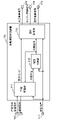
- FIG. 5 is a functional block diagram of the automatic driving control device 200 of this embodiment.
- the automatic driving control device 200 includes a behavior management section 211 , a route planning section 212 and a motion generation section 213 .
- a receiving unit is further provided when instructions are received from the outside without going through the user interface 190 .
- the behavior management unit 211 acquires work instructions, evacuation instructions, work resumption instructions, and the current position, determines the operation mode of the wheel loader 100 and transmits it to the operation generation unit 213, sets the target position, and sets the route plan. 212. Then, the target route is received from the route planning unit 212 in response to the transmission of the target position. Further, the action management unit 211 transmits the determined operation mode to the user interface 190 as one piece of notification information.
- the behavior management unit 211 receives work instructions, evacuation instructions, and work resumption instructions from the user interface 190 . Also, the current position is received from the positioning device 141 .
- the operation modes include a travel mode, an excavation mode, a loading mode, a work mode including a dumping mode, and an evacuation mode.
- the action management unit 211 determines the operation mode to be one of the travel mode, the excavation mode, the loading mode, and the dumping mode, according to the work instruction. Also, upon receiving the evacuation instruction, the operating mode is determined to be the evacuation mode. Note that the operation mode may be changed to the evacuation mode when a signal indicating that another vehicle of a predetermined type to be evacuated has entered the work area 300 among the other vehicles.
- the route planning unit 212 calculates the target route from the current position of the wheel loader 100 to the target position using the map data 220 (see FIGS. 6(a) to 6(c)), and generates motions with the action management unit 211. 213.
- the route planning section 212 receives the target position from the action managing section 211 . Also, the current position is received from the positioning device 141 .
- the motion generation unit 213 causes the work machine to travel along the target route, and moves the bucket 121 to excavate, load, and dump soil.
- the motion generation unit 213 generates a travel motion signal to cause the wheel loader 100 to travel along the target route.
- the motion generator 213 transmits the travel motion signal to the travel control device 170 as a travel control signal and to the hydraulic control device 160 as a hydraulic control signal.
- the motion generation unit 213 generates a work motion signal for the bucket 121 to perform excavation, loading, and dumping according to the motion mode.
- the motion generation unit 213 calculates the necessary engine speed from the running motion and the work motion, and transmits it to the engine control device 150 as an engine control signal.
- the traveling control signal may be the operation amount of the accelerator and brake pedals, the operation amount of the steering operation device, and the switching signal of the forward/reverse switch.
- the hydraulic control signal may be the lever operation amount of the lift arm 122 and the bucket 121 .
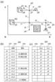
- FIG. 6(a) is a diagram for explaining the map data 220 of this embodiment
- FIGS. 6(b) and 6(c) are examples of the map data 220 of this embodiment.
- the map data 220 is generated in advance and stored in the storage device 183 or the like.
- the map data 220 comprises a plurality of points (nodes) in the work area 300 and line segments (arcs) connecting them.
- the map data 220 includes coordinates 222 and attributes 223 of each point 221, as shown in FIG. 6(b), and information on endpoints 225 and 226 of each line segment 224, as shown in FIG. 6(c). .
- Q1 and Q2 are objects to be excavated
- R1 and R2 are objects to be loaded
- O1 is an obstacle.
- the work instructions 230 include, for example, an identifier (ID) 231 assigned to each work instruction 230, an object type 232, a target loading amount 233, a loading position 234, an excavation position 235, and an earth discharge position. 236;
- the work instructions 230 are created by, for example, a management device and provided to the wheel loader 100 .
- the action management unit 211 sequentially implements the work instructions 230 .
- the work instruction 230 with the identifier Ins01 is an instruction to repeatedly excavate the object M1 at the excavation position Q1 and load it at the loading position R1, and complete the work when the loading amount reaches W1.
- the action management unit 211 When the action management unit 211 receives the work instruction 230 with the identifier Ins01, it first sets the operation mode to the running mode, sets the excavation position Q1 (p8) as the target position, and transmits it to the route planning unit 212 .
- the route planning unit 212 generates a target route 240 from the current position to the target position p8 and transmits it to the action managing unit 211 and the motion generating unit 213.
- the target route 240 includes passing points 241 including these positions from the current position to the target position, and FNR 242 indicating the traveling direction between each point.
- the FNR 242 is represented by F for forward and R for reverse.
- the behavior management unit 211 acquires the current position at predetermined time intervals, and determines whether the target position (p8) and the current position match each time the current position is acquired. If they match, it is determined that the target position (p8) has been reached, and the operation mode is set to excavation mode. While the operation mode is the excavation mode, the load of the bucket 121 is obtained from the pressure sensor 142 at predetermined time intervals, and it is determined whether or not the amount of change matches the amount of excavation. If they match, it is determined that the excavation is completed, and the operation mode is set to the running mode. After that, the loading position R1 (p6) is set as the target position and transmitted to the route planning section 212 . The route planning unit 212 generates a target route 240 from the current position (p8) to the target position (p6).
- the action management unit 211 acquires the current position at predetermined time intervals, and determines whether the target position (p6) and the current position match each time the current position is acquired. If they match, it is determined that the target position (p6) has been reached, and the operation mode is set to the loading mode. While the operation mode is the loading mode, the load of the bucket 121 is obtained from the pressure sensor 142 at predetermined time intervals, and it is determined whether or not the change amount matches the loading amount. If they match, it is determined that the loading is completed, and that the work of the work instruction 230 with the identifier Ins01 is completed.
- the action management unit 211 completes the work with the identifier Ins01, it proceeds to the work instruction 230 with the next identifier Ins02.
- the work instruction 230 with the identifier Ins02 is an instruction to excavate the object M2 at the excavation position Q2, load it at the loading position R2, and complete the work when the loading amount reaches W2.
- the excavation position and the dumping position are indicated as the same position. This means that the surplus to the target amount is discharged to the original excavation position.
- the behavior management unit 211 sets the target position to Q1 (p8), issues instructions to each unit, causes the work machine to travel in the same manner as described above, and determines that the target position (p8) has been reached.
- the operation mode is set to the dumping mode, and the dumping is carried out.
- the action management unit 211 calculates the difference ⁇ W1 between the already loaded amount and the target loaded amount W1, and uses the difference ⁇ W1 to You may comprise so that the amount of excavation may be adjusted. In this case, the action management unit 211 controls the excavation amount so as not to exceed the difference ⁇ W1 during excavation.
- the evacuation instruction 250 includes, for example, an identifier (ID) 251 assigned to each evacuation instruction 250 and an evacuation possible position 252 .
- the retractable position 252 is information of a retractable position of the wheel loader 100 within the work area 300, and a point of the map data 220 is registered.
- the retractable positions 252 of the wheel loader 100 are p0, p2, p5, and p6, as shown in FIG. 7(e).
- the evacuation instruction 250 is created by a management device or the like based on predetermined travel route information of the transport vehicle 330. Further, the evacuation instruction 250 may be created based on not only the travel route information of the transport vehicle 330 but also the work range information of other work machines that enter the work area 300 . In this embodiment, the generated evacuation instruction 250 is notified to the user, and the user inputs the evacuation instruction 250 to the automatic operation control device 200 via the user interface 190 .
- the action management unit 211 When the action management unit 211 receives the evacuation instruction 250, it executes evacuation processing. Specifically, the action management unit 211 determines the evacuation position closest to the current position among the evacuation positions 252 as the evacuation position. Then, the determined retreat position is transmitted to the route planning section 212 as the target position.
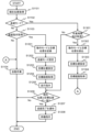
- FIG. 8 is a processing flow of action management processing of this embodiment. This process is repeated at predetermined time intervals.
- the behavior management unit 211 acquires the current position from the positioning device 141 (step S1101). In addition, when the output cycle of the positioning device 141 and the processing cycle of the action management process are different, the latest current position information is acquired from the current position information output by the positioning device 141 .
- the behavior management unit 211 determines whether the current operation mode is the evacuation mode (step S1102).
- the action management unit 211 determines whether the evacuation instruction 250 has been received from the user interface 190 (step S1103).
- the action management unit 211 performs arithmetic processing for executing automatic work (step S1104), and ends the processing. Specifically, the work is executed according to the work instruction 230 .
- step S1101 the action management unit 211 performs the processing when the evacuation instruction 250 is newly acquired.
- the behavior management unit 211 first records the current operation mode and target position in the storage device 183 (step S1201).
- the target position stored in the storage device 183 is called the final target position.
- the action management unit 211 sets the evacuation mode as the action mode (step S1202), and transmits it to the action generation unit 213.
- the behavior management unit 211 newly sets a target position (step S1203). Based on the possible evacuation position 252 given as the evacuation instruction 250 and the current position information obtained from the positioning device 141, the nearest evacuation position is selected from among the possible evacuation positions 252 and set as the target position.
- the behavior management unit 211 transmits the target position to the route planning unit 212, returns, and acquires the target route 240 (step S1204).
- the current position is p3, and an example of the target route 240 generated when the evacuation instruction 250 shown in FIG. 7(e) is received is shown in FIG. c).
- p0 which is the retractable position 252 closest to p3, is selected as the retraction position. Therefore, a target route 240 is generated that goes from p3 to p0 in reverse.
- step S1205 a running instruction is output to the motion generation unit 213 (step S1205).
- the operation mode is the save mode.
- the current position and the target position are compared to determine whether they match (step S1206). If they do not match (S1205; No), the process ends. Also at this time, the operation mode is the save mode.
- step S1207 if they match (S1206; Yes), the user is notified that saving has been completed (step S1207).
- a save completion notice is generated and sent to the user interface 190 .
- the motion generator 213 is instructed to wait at that position (step S1208). Also at this time, the operation mode is the save mode.
- step S1102 if it is in the evacuation mode (S1102; Yes), it is determined whether or not a work resumption instruction has been acquired via the user interface 190 (step S1301).
- step S1206 If the work resumption instruction has not been acquired (S1301; No), proceed to step S1206 to continue the evacuation operation. On the other hand, if a work restart instruction has been acquired (S1301; Yes), the operation mode executed before evacuation and the final target position recorded in step S1201 are read from the storage device 183 (step S1302). Then, the read final target position is set as the target position (step S 1303 ) and transmitted to the route planning section 212 . Then, according to the transmitted target position, the target route 240 is obtained from the route planning unit 212 (step S1304), the process proceeds to step S1104, and the automatic work is resumed.
- the current position is p0.
- the map data 220 of FIG. 6A when Ins01 of the work instruction 230 shown in FIG. be.
- An example of the target route 240 generated in this case is shown in FIG. 7(d).
- a target route 240 is generated that advances from p0 to p8.
- the work machine control system 180 that controls the operation of the work machine such as the wheel loader 100 of the present embodiment acquires the work instruction 230 including the final target position and the current position of the wheel loader 100.
- a behavior management unit 211 that sets a target position, a route planning unit 212 that generates a target route 240 between the current position and the target position, and a motion generation unit 213 that causes the wheel loader 100 to travel along the target route.
- the action management unit 211 determines an evacuation position from among evacuation possible positions 252 included in the evacuation instruction 250 based on at least one of the current position and the final target position, The retracted position is set as the target position.
- the present embodiment it is possible to select the optimum evacuation position according to the current position of the own vehicle (wheel loader 100) when the evacuation instruction 250 is received. For example, if there are multiple retractable positions, the retractable position closest to the current position is selected as the retraction position. As a result, the retraction distance can be shortened, and the work interruption time can be shortened. That is, according to the control system 180 of the present embodiment, it is possible to minimize the decrease in work efficiency due to evacuation while avoiding contact with the dump truck and other working machines.
- the retractable position 252 is included in the retraction instruction 250 in the above embodiment.
- the retractable position may be generated by the automatic operation control device 200 .
- the automatic driving control device 200 includes an evacuation position generator that generates an evacuation position according to the work range information of the entering vehicle.
- the retractable position generation unit receives the work range information of the vehicle. Based on this work range information, the evacuation position 252 is specified on the map data 220 .
- the retractable position closest to the current position is set as the retractable position, but the present invention is not limited to this.
- the retractable position closest to the final target position may be set as the retracted position.
- the configuration of the wheel loader 100 of this embodiment is the same as that of the first embodiment. Also, the control system 180 is the same as in the first embodiment.
- FIG. 9 is a functional block diagram of the automatic driving control device 200 of this embodiment.
- the automatic driving control device 200 of the present embodiment has the configuration of the first embodiment (behavior management unit 211, route planning unit 212, motion generation unit 213), and further , and an anomaly detector 214 .
- the abnormality detection unit 214 confirms the soundness of the wheel loader 100, and if there is an abnormality, transmits an evacuation instruction 250 to the action management unit 211.
- Abnormalities assumed here include, for example, failure of each device constituting the wheel loader 100, breakage of electrical, mechanical, and hydraulic connection points, communication delays of sensors and controllers, and the like.
- the abnormality detection unit 214 determines whether there is an abnormality based on sensor signals from various sensors installed (mounted) in each part of the wheel loader 100 (hereinafter referred to as mounted sensors 143).
- the mounted sensors 143 are, for example, a vehicle speed sensor, a steering angle sensor, a positioning device for acquiring self-position, various pressure sensors (lift, bucket, brake, etc.).
- the abnormality detection unit 214 determines that there is an abnormality when the mounted sensor outputs a sensor signal indicating that the soundness of the actuators and peripheral devices for realizing running and working operations cannot be confirmed.
- the action management unit 211 When the action management unit 211 receives at least one of the evacuation instruction 250 transmitted from the user interface 190 and the evacuation instruction 250 transmitted from the anomaly detection unit 214, it executes evacuation processing similar to the first embodiment.
- control system 180 of the wheel loader 100 of this embodiment further includes the abnormality detection section 214 that transmits the evacuation instruction 250 to the action management section 211 when an abnormality of the wheel loader 100 is detected.
- the arithmetic processing at the time of evacuation described in the first embodiment is performed not only based on the evacuation instruction 250 from the user, but also based on the abnormality detection of the wheel loader 100. do. In this way, by widening the application range of the process during evacuation, it is possible to shorten the interruption time of work even in the event of an abnormality, as in the first embodiment, and to minimize the decrease in work efficiency.
- the retractable position closest to either the current position or the final target position is set as the retracting position.
- the retractable position at which the entire travel route is the shortest is set as the retracted position.
- the present embodiment will be described with a focus on the configuration different from the first embodiment.
- a case will be explained by comparing the total traveling distances when the retractable position closest to the current position and the retractable position closest to the final target position are each set as the retracted position and determined.
- the wheel loader 100 of this embodiment is the same as that of the first embodiment.
- the control system is the same as in the first embodiment.
- the functional blocks and hardware configuration of the automatic driving control device 200 are the same as in the first embodiment.
- the functions of the action management unit 211 and the route planning unit 212 are different.
- the action management unit 211 of this embodiment Upon receiving an evacuation instruction, the action management unit 211 of this embodiment extracts the evacuation possible position closest to the current position as a first evacuation position candidate, as in the first embodiment. Furthermore, in the present embodiment, the closest possible retraction position from the target position at that time is extracted as the second retraction position candidate. The action management section 211 transmits the first and second evacuation position candidates to the route planning section 212 along with the current position and the final target position.
- the route planning unit 212 When the route planning unit 212 receives the route points from the action management unit 211, it calculates a target route that passes through the route points. In this embodiment, when the evacuation position candidate is received from the action management unit 211, a target route from the current position to the final target position is calculated for each evacuation position candidate, and each target route candidate to the behavior management unit 211.
- the action management unit 211 determines the evacuation position based on the target route candidate for each evacuation position candidate received from the route planning unit 212 .
- the evacuation position candidate with the shortest travel distance calculated based on the target route candidate is determined as the evacuation position.
- the traveled distance is calculated based on map data 220 .
- the route planning unit 212 is notified of the retreat position as the target position.
- the action management process by the action management unit 211 of this embodiment is basically the same as the action management process of the first embodiment. However, the process for setting the target position in step S1203 is different.
- FIG. 10 shows the flow of the target position setting process in step S1203 of this embodiment, that is, the target position setting process in the evacuation mode.
- the action management unit 211 first sets a retreat position candidate (step S3101).
- the possible evacuation position closest to the current position and the possible evacuation position closest to the final target position are extracted as evacuation position candidates. do.
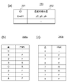
- Map data 220 shown in FIGS. 6(a) to 6(c) is provided, and when the current position is p0, the final target position is p8, and the evacuation instruction 250 shown in FIG. 11(a) is received, it is extracted.
- Retreat position candidates will be explained. Three locations p2, p5, and p6 are registered as retractable positions 252 in this retraction instruction 250 .
- the retraction position candidate (first retraction position candidate) extracted as the closest retractable position from the current position p0 is p2.
- a retraction position candidate (second retraction position candidate) extracted as a retractable position closest to the final target position p8 is p6.
- the behavior management unit 211 sets each extracted evacuation position candidate as a waypoint (step S3102).
- each evacuation position candidate is transmitted to the route planning unit 212 as a waypoint.
- the action management unit 211 turns around and acquires a target route candidate for each evacuation position candidate (step S3103).
- a target route candidate (first target route candidate) is generated that goes from the current position p0 to the final target position p8 via the first evacuation position candidate p2.
- the first target route candidate 240a is shown in FIG. 11(b). As shown in this figure, the first target route candidate 240a is generated as F (forward) from p0 to p2, R (reverse) from p2 to p3 to p0, and F from p8 to p8.
- a target route candidate (second target route candidate) is generated that goes from the current position p0 to the final target position p8 via the second evacuation position candidate p6.
- the second target route candidate 240b is shown in FIG. 11(c). As shown in this figure, the second target route candidate 240b is generated as F from p0 through p3 and p7 to p6, then R through p7 to p9, and F through p7 to p8.
- the action management unit 211 calculates the travel distance of each target route and identifies the target route candidate with the shortest travel distance (step S3104).
- the coordinate value of each point is used to calculate the distance between each point, and the total sum is taken as the traveling distance.
- the behavior management unit 211 determines the evacuation position candidate in the identified target route candidate as the evacuation position (step S3105). Then, the determined retraction position is set as the target position (step S3106).
- the action management unit 211 moves from the current position to the final target via each of the plurality of evacuation position candidates selected from the evacuation possible positions 252.
- the evacuation position candidate through which the target route candidate with the shortest travel distance passes is determined as the evacuation position.
- the route with the shortest total travel distance is selected from among a plurality of possible evacuation positions for all work instructions executed by the wheel loader 100 .
- the action management unit 211 extracts all possible evacuation positions as evacuation position candidates and transmits them to the route planning unit 212 in step S3101. Then, the route planning unit 212 calculates target route candidates for all the evacuation position candidates (evacuable positions), and returns them to the action management unit 211 .
- the action management unit 211 calculates the travel distances for all target route candidates, selects the shortest one from among them, and determines the evacuation position candidate (evacuable position) used in the target route candidate as the evacuation position. , set to the target position.
- this embodiment may include the abnormality detection unit 214 as in the second embodiment.
- the work instruction 230, the evacuation instruction 250, and the work resumption instruction have been described as input by the user via the user interface 190.
- the automatic driving control device 200 may be provided with a receiving section and receive directly via the receiving section.
- a receiving unit is implemented by the communication I/F 185 .
- the management device or the like creates these instructions and transmits them to the automatic operation control device 200 .
- the behavior management unit 211 identifies the evacuation position based on these pieces of information and the map data 220 .
- the present invention is applied to the wheel loader 100, but the application target of the present invention is not limited to this, and can also be applied to working machines other than the wheel loader 100, such as hydraulic excavators. .
- working machines such as hydraulic excavators.
- the traveling distance for evacuation can be minimized, resulting in higher efficiency.
Landscapes
- Engineering & Computer Science (AREA)
- Mining & Mineral Resources (AREA)
- Civil Engineering (AREA)
- General Engineering & Computer Science (AREA)
- Structural Engineering (AREA)
- Mechanical Engineering (AREA)
- Operation Control Of Excavators (AREA)
- Component Parts Of Construction Machinery (AREA)
- Control Of Driving Devices And Active Controlling Of Vehicle (AREA)
- Control Of Position, Course, Altitude, Or Attitude Of Moving Bodies (AREA)
Abstract
Description
まず、第一実施形態の概要を、図1を用いて説明する。本実施形態では、作業領域300内を自動走行する例えば、ホイールローダ等の作業機械100が、作業指示に従って、掘削対象310を掘削し、掘削した対象物を積込対象320まで運搬することを繰り返す。そこに、作業機械100とは異なる動作をする運搬車両330が侵入する。運搬車両330は、例えば、積込対象320に積み込まれた対象物を、作業領域300外に運搬したり、掘削対象310を補充したりする、ダンプトラック等である。なお、作業領域全体の制御を行う管理装置(管理センタに備えられたコンピュータ)等を備えていてもよい。
なお、上記実施形態では、退避可能位置252は退避指示250に含まれる。しかしながら、退避可能位置を、自動運転制御装置200で生成してもよい。この場合、自動運転制御装置200は、進入する車両の作業範囲情報に応じて、退避可能位置を生成する退避可能位置生成部を備える。
上記実施形態では、現在位置に最も近い退避可能位置を退避位置に設定しているが、これに限定されない。例えば、最終目標位置に最も近い退避可能位置を退避位置に設定してもよい。
次に、本発明の第二実施形態を説明する。第一実施形態では、運搬車両330等の他車両が作業領域300に入った場合、退避指示250が出される。本実施形態では、さらに、ホイールローダ100に異常が発生した場合も、退避指示250が出される。
次に、本発明の第三実施形態を説明する。第一実施形態および第二実施形態では、退避時、現在位置および最終目標位置のいずれかに最も近い退避可能位置を退避位置と設定する。一方、本実施形態では、全体の走行経路が最も短くなる退避可能位置を退避位置に設定する。
なお、上記実施形態では、退避位置候補として、現在位置に最も近い退避可能位置および最終目標位置に最も近い退避可能位置のみを抽出しているが、これに限定されない。例えば、退避可能位置全てを抽出してもよい。
なお、本実施形態は、第二実施形態同様、異常検知部214を備えてもよい。
また、上記各実施形態および変形例において、作業指示230,退避指示250、作業再開指示は、ユーザがユーザインタフェース190を介して入力するものとして説明したが、これらの各指示の取得は、これに限定されない。例えば、自動運転制御装置200が、受信部を備え、受信部を介して、直接受信してもよい。受信部は、通信I/F185により実現される。この場合、管理装置等がこれらの指示を作成し、自動運転制御装置200に送信する。
200:自動運転制御装置(制御装置)、211:行動管理部、212:経路計画部、213:動作生成部、214:異常検知部、220:マップデータ、221:点、222:座標、223:属性、224:線分、225:端点、226:端点、230:作業指示、231:識別子(ID)、232:種別、233:目標積込量、234:積込位置、235:掘削位置、236:放土位置、240:目標経路、240a:第一目標経路候補、240b:第二目標経路候補、241:通過点、242:FNR、250:退避指示、251:識別子(ID)、252:退避可能位置、
300:作業領域、310:掘削対象、320:積込対象、330:運搬車両
Claims (7)
- 作業機械を動作させる制御装置を備えた、作業機械の制御システムであって、
前記制御装置は、
前記作業機械が実行する作業の情報を含む作業指示と前記作業機械の現在位置とを取得し、前記作業指示と前記現在位置とに基づいて目標位置を設定する行動管理部と、
前記現在位置と前記目標位置との間の目標経路を生成する経路計画部と、
前記目標経路に従って、前記作業機械を走行させる動作生成部と、を備え、
前記行動管理部は、前記作業機械とは別の作業機械の作業範囲に基づいた退避可能位置を含む退避指示を受信し、前記退避指示を受信した場合、別の作業機械の前記作業範囲および前記作業機械の前記現在位置に基づいて、前記退避可能位置の中から退避位置を決定し、前記退避位置を前記目標位置に設定すること
を特徴とする作業機械の制御システム。 - 請求項1記載の作業機械の制御システムであって、
前記制御装置は、
前記作業機械の異常に係る信号を取得し、前記作業機械に異常があることを検知した場合、前記退避指示を前記行動管理部に送信する異常検知部をさらに備えること
を特徴とする作業機械の制御システム。 - 請求項1記載の作業機械の制御システムであって、
前記行動管理部は、前記退避可能位置の中から、前記現在位置に最も近い前記退避可能位置を、前記退避位置に決定すること
を特徴とする作業機械の制御システム。 - 請求項1記載の作業機械の制御システムであって、
前記作業指示には、最終目標位置の情報を含み、
前記行動管理部は、前記退避可能位置から選択された複数の退避位置候補それぞれを経由して前記現在位置から前記最終目標位置に至る各目標経路候補の中で、最も走行距離の短い目標経路候補が経由する前記退避位置候補を、前記退避位置と決定すること
を特徴とする作業機械の制御システム。 - 請求項4記載の作業機械の制御システムであって、
前記行動管理部は、複数の前記退避位置候補として、前記現在位置に最も近い退避可能位置である第一退避位置候補と、前記最終目標位置に最も近い退避可能位置である第二退避位置候補とを選択すること
を特徴とする作業機械の制御システム。 - 請求項1記載の作業機械の制御システムであって、
前記行動管理部は、前記作業機械が前記退避位置に到達した場合、前記作業指示を入力するための入力装置に退避動作の完了を示す情報を出力すること
を特徴とする作業機械の制御システム。 - 請求項1から6のいずれか1項記載の作業機械の制御システムを搭載した、作業機械。
Priority Applications (5)
| Application Number | Priority Date | Filing Date | Title |
|---|---|---|---|
| EP22872641.0A EP4407103A4 (en) | 2021-09-24 | 2022-08-26 | CONSTRUCTION MACHINERY CONTROL SYSTEM AND CONSTRUCTION MACHINERY |
| KR1020237029016A KR20230134586A (ko) | 2021-09-24 | 2022-08-26 | 작업 기계의 제어 시스템 및 작업 기계 |
| CN202280016633.4A CN116888329B (zh) | 2021-09-24 | 2022-08-26 | 作业机械的控制系统以及作业机械 |
| US18/279,477 US12534876B2 (en) | 2021-09-24 | 2022-08-26 | Work machine control system, and work machine |
| JP2023549431A JP7401719B2 (ja) | 2021-09-24 | 2022-08-26 | 作業機械の制御システムおよび作業機械 |
Applications Claiming Priority (2)
| Application Number | Priority Date | Filing Date | Title |
|---|---|---|---|
| JP2021155407 | 2021-09-24 | ||
| JP2021-155407 | 2021-09-24 |
Publications (1)
| Publication Number | Publication Date |
|---|---|
| WO2023047885A1 true WO2023047885A1 (ja) | 2023-03-30 |
Family
ID=85720546
Family Applications (1)
| Application Number | Title | Priority Date | Filing Date |
|---|---|---|---|
| PCT/JP2022/032212 Ceased WO2023047885A1 (ja) | 2021-09-24 | 2022-08-26 | 作業機械の制御システムおよび作業機械 |
Country Status (6)
| Country | Link |
|---|---|
| US (1) | US12534876B2 (ja) |
| EP (1) | EP4407103A4 (ja) |
| JP (1) | JP7401719B2 (ja) |
| KR (1) | KR20230134586A (ja) |
| CN (1) | CN116888329B (ja) |
| WO (1) | WO2023047885A1 (ja) |
Cited By (3)
| Publication number | Priority date | Publication date | Assignee | Title |
|---|---|---|---|---|
| WO2025004497A1 (ja) * | 2023-06-28 | 2025-01-02 | 株式会社小松製作所 | 作業機械を制御するためのシステム |
| WO2025204569A1 (ja) * | 2024-03-29 | 2025-10-02 | 株式会社小松製作所 | 作業機械を含むシステム、作業機械、および作業機械の自動走行制御方法 |
| WO2026013988A1 (ja) * | 2024-07-08 | 2026-01-15 | 株式会社小松製作所 | 方法、作業機械用コントローラ、および作業機械を含むシステム |
Families Citing this family (1)
| Publication number | Priority date | Publication date | Assignee | Title |
|---|---|---|---|---|
| JP2025114291A (ja) * | 2024-01-24 | 2025-08-05 | 株式会社小松製作所 | 作業機械の制御システム及び作業機械の制御方法 |
Citations (5)
| Publication number | Priority date | Publication date | Assignee | Title |
|---|---|---|---|---|
| WO2015087430A1 (ja) * | 2013-12-12 | 2015-06-18 | 日立建機株式会社 | 車両走行システム及び車両走行制御方法 |
| JP2018181120A (ja) | 2017-04-18 | 2018-11-15 | 株式会社デンソーテン | 運転支援装置及び運転支援方法 |
| JP2018193038A (ja) | 2017-05-22 | 2018-12-06 | 本田技研工業株式会社 | 自動走行制御装置 |
| JP2019214831A (ja) * | 2018-06-11 | 2019-12-19 | 株式会社フジタ | 作業機械の遠隔制御システム |
| WO2020217977A1 (ja) * | 2019-04-24 | 2020-10-29 | 株式会社小松製作所 | 作業機械を制御するためのシステムおよび方法 |
Family Cites Families (12)
| Publication number | Priority date | Publication date | Assignee | Title |
|---|---|---|---|---|
| US5987379A (en) * | 1997-10-30 | 1999-11-16 | Trimble Navigation Limited | Creation and monitoring of variable buffer zones |
| JP3891700B2 (ja) * | 1998-07-08 | 2007-03-14 | 富士重工業株式会社 | 誘導走行を行う走行車 |
| DE102004027242A1 (de) * | 2004-06-03 | 2005-12-22 | Claas Selbstfahrende Erntemaschinen Gmbh | Routenplanungssystem für landwirtschaftliche Arbeitsmaschinen |
| JP5866645B2 (ja) * | 2011-06-17 | 2016-02-17 | 株式会社小松製作所 | 無人走行車両の走行禁止領域設定システム及び無人走行車両の走行禁止領域設定用コンピュータプログラム |
| JP6064946B2 (ja) * | 2014-05-30 | 2017-01-25 | 株式会社デンソー | 退避走行支援装置 |
| DE102016203727A1 (de) * | 2016-03-08 | 2017-09-14 | Robert Bosch Gmbh | Verfahren zum Vermeiden eines Auffahrunfalls zwischen einem ersten Fahrzeug und einem zweiten Fahrzeug und Steuergerät |
| JP6919531B2 (ja) * | 2017-11-30 | 2021-08-18 | 井関農機株式会社 | 作業車両 |
| JP6953343B2 (ja) * | 2018-03-27 | 2021-10-27 | ヤンマーパワーテクノロジー株式会社 | 自動走行システム |
| US10831213B2 (en) * | 2018-03-30 | 2020-11-10 | Deere & Company | Targeted loading assistance system |
| JP7094832B2 (ja) * | 2018-08-23 | 2022-07-04 | ヤンマーパワーテクノロジー株式会社 | 協調作業システム |
| JP7296823B2 (ja) * | 2019-08-23 | 2023-06-23 | 株式会社安藤・間 | 自動運転式建設機械制御システム、及び自動運転式建設機械制御方法 |
| US11378964B2 (en) * | 2019-10-28 | 2022-07-05 | Caterpillar Inc. | Systems and methods for autonomous movement of material |
-
2022
- 2022-08-26 EP EP22872641.0A patent/EP4407103A4/en active Pending
- 2022-08-26 CN CN202280016633.4A patent/CN116888329B/zh active Active
- 2022-08-26 KR KR1020237029016A patent/KR20230134586A/ko not_active Ceased
- 2022-08-26 JP JP2023549431A patent/JP7401719B2/ja active Active
- 2022-08-26 US US18/279,477 patent/US12534876B2/en active Active
- 2022-08-26 WO PCT/JP2022/032212 patent/WO2023047885A1/ja not_active Ceased
Patent Citations (5)
| Publication number | Priority date | Publication date | Assignee | Title |
|---|---|---|---|---|
| WO2015087430A1 (ja) * | 2013-12-12 | 2015-06-18 | 日立建機株式会社 | 車両走行システム及び車両走行制御方法 |
| JP2018181120A (ja) | 2017-04-18 | 2018-11-15 | 株式会社デンソーテン | 運転支援装置及び運転支援方法 |
| JP2018193038A (ja) | 2017-05-22 | 2018-12-06 | 本田技研工業株式会社 | 自動走行制御装置 |
| JP2019214831A (ja) * | 2018-06-11 | 2019-12-19 | 株式会社フジタ | 作業機械の遠隔制御システム |
| WO2020217977A1 (ja) * | 2019-04-24 | 2020-10-29 | 株式会社小松製作所 | 作業機械を制御するためのシステムおよび方法 |
Non-Patent Citations (1)
| Title |
|---|
| See also references of EP4407103A4 |
Cited By (3)
| Publication number | Priority date | Publication date | Assignee | Title |
|---|---|---|---|---|
| WO2025004497A1 (ja) * | 2023-06-28 | 2025-01-02 | 株式会社小松製作所 | 作業機械を制御するためのシステム |
| WO2025204569A1 (ja) * | 2024-03-29 | 2025-10-02 | 株式会社小松製作所 | 作業機械を含むシステム、作業機械、および作業機械の自動走行制御方法 |
| WO2026013988A1 (ja) * | 2024-07-08 | 2026-01-15 | 株式会社小松製作所 | 方法、作業機械用コントローラ、および作業機械を含むシステム |
Also Published As
| Publication number | Publication date |
|---|---|
| CN116888329A (zh) | 2023-10-13 |
| CN116888329B (zh) | 2026-02-27 |
| JP7401719B2 (ja) | 2023-12-19 |
| EP4407103A1 (en) | 2024-07-31 |
| KR20230134586A (ko) | 2023-09-21 |
| EP4407103A4 (en) | 2025-08-13 |
| US12534876B2 (en) | 2026-01-27 |
| US20240301656A1 (en) | 2024-09-12 |
| JPWO2023047885A1 (ja) | 2023-03-30 |
Similar Documents
| Publication | Publication Date | Title |
|---|---|---|
| JP7401719B2 (ja) | 作業機械の制御システムおよび作業機械 | |
| JP7107737B2 (ja) | 車両管制システム | |
| AU2017218993B2 (en) | Control system for a machine | |
| US12460388B2 (en) | Control device and control method for work machine | |
| WO2012073950A1 (ja) | 無人車両の走行システムにおける走行制御方法および無人車両の走行システム | |
| EP4212676A1 (en) | Route setting system | |
| CN115298632A (zh) | 作业机械 | |
| WO2024057961A1 (ja) | 作業機械を含むシステム、作業機械のコントローラ、および作業機械の制御方法 | |
| WO2020195044A1 (ja) | 作業機械の制御システム及び方法 | |
| KR102423054B1 (ko) | 자율 주행 방법 및 이를 이용하는 무인 도저 | |
| WO2022130756A1 (ja) | 複数の作業機械を制御するためのシステム及び方法 | |
| WO2024176867A1 (ja) | 作業機械を含むシステム、作業機械用コントローラ、および作業機械の経路生成方法 | |
| WO2024043075A1 (ja) | 作業機械、作業機械を含むシステム、および作業機械の制御方法 | |
| WO2024057959A1 (ja) | 作業機械を含むシステム、作業機械のコントローラ、および作業機械の制御方法 | |
| JP7722829B2 (ja) | 作業機械の制御システムおよび作業機械 | |
| JPH11350534A (ja) | 土工機械のための走査センサ設備 | |
| JP2024030581A (ja) | 作業機械、作業機械を含むシステム、および作業機械の制御方法 | |
| WO2026013988A1 (ja) | 方法、作業機械用コントローラ、および作業機械を含むシステム | |
| WO2024053443A1 (ja) | 作業機械、作業機械を含むシステム、および作業機械の制御方法 | |
| WO2025052756A1 (ja) | 作業機械 | |
| JP2024048983A (ja) | 作業機械の自動制御システム | |
| KR20250133394A (ko) | 작업 기계의 제어 시스템 | |
| WO2024062899A1 (ja) | 作業機械を含むシステム、および作業機械の制御方法 | |
| JP2025153585A (ja) | 作業機械を含むシステム、作業機械、および作業機械の自動走行制御方法 | |
| WO2024176868A1 (ja) | 作業機械を含むシステム、作業機械用コントローラ、および作業機械の経路生成方法 |
Legal Events
| Date | Code | Title | Description |
|---|---|---|---|
| 121 | Ep: the epo has been informed by wipo that ep was designated in this application |
Ref document number: 22872641 Country of ref document: EP Kind code of ref document: A1 |
|
| WWE | Wipo information: entry into national phase |
Ref document number: 2023549431 Country of ref document: JP |
|
| WWE | Wipo information: entry into national phase |
Ref document number: 202280016633.4 Country of ref document: CN |
|
| ENP | Entry into the national phase |
Ref document number: 20237029016 Country of ref document: KR Kind code of ref document: A |
|
| WWE | Wipo information: entry into national phase |
Ref document number: 1020237029016 Country of ref document: KR |
|
| WWE | Wipo information: entry into national phase |
Ref document number: 18279477 Country of ref document: US |
|
| WWE | Wipo information: entry into national phase |
Ref document number: 2022872641 Country of ref document: EP |
|
| NENP | Non-entry into the national phase |
Ref country code: DE |
|
| ENP | Entry into the national phase |
Ref document number: 2022872641 Country of ref document: EP Effective date: 20240424 |
|
| WWG | Wipo information: grant in national office |
Ref document number: 18279477 Country of ref document: US |
|
| WWR | Wipo information: refused in national office |
Ref document number: 1020237029016 Country of ref document: KR |