WO2023047891A1 - 超音波内視鏡システム、及び超音波内視鏡システムの作動方法 - Google Patents
超音波内視鏡システム、及び超音波内視鏡システムの作動方法 Download PDFInfo
- Publication number
- WO2023047891A1 WO2023047891A1 PCT/JP2022/032373 JP2022032373W WO2023047891A1 WO 2023047891 A1 WO2023047891 A1 WO 2023047891A1 JP 2022032373 W JP2022032373 W JP 2022032373W WO 2023047891 A1 WO2023047891 A1 WO 2023047891A1
- Authority
- WO
- WIPO (PCT)
- Prior art keywords
- ultrasonic
- transmission
- transducers
- image
- polarization
- Prior art date
- Legal status (The legal status is an assumption and is not a legal conclusion. Google has not performed a legal analysis and makes no representation as to the accuracy of the status listed.)
- Ceased
Links
Images







Classifications
-
- G—PHYSICS
- G01—MEASURING; TESTING
- G01S—RADIO DIRECTION-FINDING; RADIO NAVIGATION; DETERMINING DISTANCE OR VELOCITY BY USE OF RADIO WAVES; LOCATING OR PRESENCE-DETECTING BY USE OF THE REFLECTION OR RERADIATION OF RADIO WAVES; ANALOGOUS ARRANGEMENTS USING OTHER WAVES
- G01S15/00—Systems using the reflection or reradiation of acoustic waves, e.g. sonar systems
- G01S15/88—Sonar systems specially adapted for specific applications
- G01S15/89—Sonar systems specially adapted for specific applications for mapping or imaging
- G01S15/8906—Short-range imaging systems; Acoustic microscope systems using pulse-echo techniques
- G01S15/8909—Short-range imaging systems; Acoustic microscope systems using pulse-echo techniques using a static transducer configuration
- G01S15/8915—Short-range imaging systems; Acoustic microscope systems using pulse-echo techniques using a static transducer configuration using a transducer array
- G01S15/892—Short-range imaging systems; Acoustic microscope systems using pulse-echo techniques using a static transducer configuration using a transducer array the array being curvilinear
-
- A—HUMAN NECESSITIES
- A61—MEDICAL OR VETERINARY SCIENCE; HYGIENE
- A61B—DIAGNOSIS; SURGERY; IDENTIFICATION
- A61B1/00—Instruments for performing medical examinations of the interior of cavities or tubes of the body by visual or photographical inspection, e.g. endoscopes; Illuminating arrangements therefor
-
- A—HUMAN NECESSITIES
- A61—MEDICAL OR VETERINARY SCIENCE; HYGIENE
- A61B—DIAGNOSIS; SURGERY; IDENTIFICATION
- A61B8/00—Diagnosis using ultrasonic, sonic or infrasonic waves
- A61B8/12—Diagnosis using ultrasonic, sonic or infrasonic waves in body cavities or body tracts, e.g. by using catheters
-
- A—HUMAN NECESSITIES
- A61—MEDICAL OR VETERINARY SCIENCE; HYGIENE
- A61B—DIAGNOSIS; SURGERY; IDENTIFICATION
- A61B8/00—Diagnosis using ultrasonic, sonic or infrasonic waves
- A61B8/44—Constructional features of the ultrasonic, sonic or infrasonic diagnostic device
- A61B8/4444—Constructional features of the ultrasonic, sonic or infrasonic diagnostic device related to the probe
- A61B8/445—Details of catheter construction
-
- A—HUMAN NECESSITIES
- A61—MEDICAL OR VETERINARY SCIENCE; HYGIENE
- A61B—DIAGNOSIS; SURGERY; IDENTIFICATION
- A61B8/00—Diagnosis using ultrasonic, sonic or infrasonic waves
- A61B8/44—Constructional features of the ultrasonic, sonic or infrasonic diagnostic device
- A61B8/4483—Constructional features of the ultrasonic, sonic or infrasonic diagnostic device characterised by features of the ultrasound transducer
-
- A—HUMAN NECESSITIES
- A61—MEDICAL OR VETERINARY SCIENCE; HYGIENE
- A61B—DIAGNOSIS; SURGERY; IDENTIFICATION
- A61B8/00—Diagnosis using ultrasonic, sonic or infrasonic waves
- A61B8/44—Constructional features of the ultrasonic, sonic or infrasonic diagnostic device
- A61B8/4483—Constructional features of the ultrasonic, sonic or infrasonic diagnostic device characterised by features of the ultrasound transducer
- A61B8/4488—Constructional features of the ultrasonic, sonic or infrasonic diagnostic device characterised by features of the ultrasound transducer the transducer being a phased array
-
- A—HUMAN NECESSITIES
- A61—MEDICAL OR VETERINARY SCIENCE; HYGIENE
- A61B—DIAGNOSIS; SURGERY; IDENTIFICATION
- A61B8/00—Diagnosis using ultrasonic, sonic or infrasonic waves
- A61B8/44—Constructional features of the ultrasonic, sonic or infrasonic diagnostic device
- A61B8/4483—Constructional features of the ultrasonic, sonic or infrasonic diagnostic device characterised by features of the ultrasound transducer
- A61B8/4494—Constructional features of the ultrasonic, sonic or infrasonic diagnostic device characterised by features of the ultrasound transducer characterised by the arrangement of the transducer elements
-
- A—HUMAN NECESSITIES
- A61—MEDICAL OR VETERINARY SCIENCE; HYGIENE
- A61B—DIAGNOSIS; SURGERY; IDENTIFICATION
- A61B8/00—Diagnosis using ultrasonic, sonic or infrasonic waves
- A61B8/52—Devices using data or image processing specially adapted for diagnosis using ultrasonic, sonic or infrasonic waves
- A61B8/5207—Devices using data or image processing specially adapted for diagnosis using ultrasonic, sonic or infrasonic waves involving processing of raw data to produce diagnostic data, e.g. for generating an image
-
- A—HUMAN NECESSITIES
- A61—MEDICAL OR VETERINARY SCIENCE; HYGIENE
- A61B—DIAGNOSIS; SURGERY; IDENTIFICATION
- A61B8/00—Diagnosis using ultrasonic, sonic or infrasonic waves
- A61B8/54—Control of the diagnostic device
-
- G—PHYSICS
- G01—MEASURING; TESTING
- G01S—RADIO DIRECTION-FINDING; RADIO NAVIGATION; DETERMINING DISTANCE OR VELOCITY BY USE OF RADIO WAVES; LOCATING OR PRESENCE-DETECTING BY USE OF THE REFLECTION OR RERADIATION OF RADIO WAVES; ANALOGOUS ARRANGEMENTS USING OTHER WAVES
- G01S15/00—Systems using the reflection or reradiation of acoustic waves, e.g. sonar systems
- G01S15/88—Sonar systems specially adapted for specific applications
- G01S15/89—Sonar systems specially adapted for specific applications for mapping or imaging
- G01S15/8906—Short-range imaging systems; Acoustic microscope systems using pulse-echo techniques
- G01S15/8909—Short-range imaging systems; Acoustic microscope systems using pulse-echo techniques using a static transducer configuration
- G01S15/8915—Short-range imaging systems; Acoustic microscope systems using pulse-echo techniques using a static transducer configuration using a transducer array
- G01S15/8927—Short-range imaging systems; Acoustic microscope systems using pulse-echo techniques using a static transducer configuration using a transducer array using simultaneously or sequentially two or more subarrays or subapertures
-
- G—PHYSICS
- G01—MEASURING; TESTING
- G01S—RADIO DIRECTION-FINDING; RADIO NAVIGATION; DETERMINING DISTANCE OR VELOCITY BY USE OF RADIO WAVES; LOCATING OR PRESENCE-DETECTING BY USE OF THE REFLECTION OR RERADIATION OF RADIO WAVES; ANALOGOUS ARRANGEMENTS USING OTHER WAVES
- G01S15/00—Systems using the reflection or reradiation of acoustic waves, e.g. sonar systems
- G01S15/88—Sonar systems specially adapted for specific applications
- G01S15/89—Sonar systems specially adapted for specific applications for mapping or imaging
- G01S15/8906—Short-range imaging systems; Acoustic microscope systems using pulse-echo techniques
- G01S15/899—Combination of imaging systems with ancillary equipment
-
- G—PHYSICS
- G01—MEASURING; TESTING
- G01S—RADIO DIRECTION-FINDING; RADIO NAVIGATION; DETERMINING DISTANCE OR VELOCITY BY USE OF RADIO WAVES; LOCATING OR PRESENCE-DETECTING BY USE OF THE REFLECTION OR RERADIATION OF RADIO WAVES; ANALOGOUS ARRANGEMENTS USING OTHER WAVES
- G01S7/00—Details of systems according to groups G01S13/00, G01S15/00, G01S17/00
- G01S7/52—Details of systems according to groups G01S13/00, G01S15/00, G01S17/00 of systems according to group G01S15/00
- G01S7/52017—Details of systems according to groups G01S13/00, G01S15/00, G01S17/00 of systems according to group G01S15/00 particularly adapted to short-range imaging
- G01S7/52019—Details of transmitters
- G01S7/5202—Details of transmitters for pulse systems
-
- G—PHYSICS
- G01—MEASURING; TESTING
- G01S—RADIO DIRECTION-FINDING; RADIO NAVIGATION; DETERMINING DISTANCE OR VELOCITY BY USE OF RADIO WAVES; LOCATING OR PRESENCE-DETECTING BY USE OF THE REFLECTION OR RERADIATION OF RADIO WAVES; ANALOGOUS ARRANGEMENTS USING OTHER WAVES
- G01S7/00—Details of systems according to groups G01S13/00, G01S15/00, G01S17/00
- G01S7/52—Details of systems according to groups G01S13/00, G01S15/00, G01S17/00 of systems according to group G01S15/00
- G01S7/52017—Details of systems according to groups G01S13/00, G01S15/00, G01S17/00 of systems according to group G01S15/00 particularly adapted to short-range imaging
- G01S7/52046—Techniques for image enhancement involving transmitter or receiver
-
- G—PHYSICS
- G01—MEASURING; TESTING
- G01S—RADIO DIRECTION-FINDING; RADIO NAVIGATION; DETERMINING DISTANCE OR VELOCITY BY USE OF RADIO WAVES; LOCATING OR PRESENCE-DETECTING BY USE OF THE REFLECTION OR RERADIATION OF RADIO WAVES; ANALOGOUS ARRANGEMENTS USING OTHER WAVES
- G01S7/00—Details of systems according to groups G01S13/00, G01S15/00, G01S17/00
- G01S7/52—Details of systems according to groups G01S13/00, G01S15/00, G01S17/00 of systems according to group G01S15/00
- G01S7/52017—Details of systems according to groups G01S13/00, G01S15/00, G01S17/00 of systems according to group G01S15/00 particularly adapted to short-range imaging
- G01S7/52053—Display arrangements
- G01S7/52057—Cathode ray tube displays
- G01S7/52074—Composite displays, e.g. split-screen displays; Combination of multiple images or of images and alphanumeric tabular information
Definitions
- the present invention relates to an ultrasonic endoscope system that performs polarization processing on a plurality of ultrasonic transducers provided in an ultrasonic endoscope, and an ultrasonic endoscope system operating method.
- An ultrasonic endoscope having an ultrasonic observation section at the distal end of an endoscope is used as an ultrasonic diagnostic apparatus for observing the bile and pancreas through the gastrointestinal tract.
- Such an ultrasonic diagnostic apparatus acquires an ultrasonic image of the inside of the body cavity of the subject by driving a plurality of ultrasonic transducers in the body cavity of the subject and transmitting and receiving ultrasonic waves.
- it is necessary to avoid a decrease in sensitivity while the apparatus is inside the body cavity of the subject.
- a plurality of ultrasonic transducers in an ultrasonic diagnostic apparatus are composed of, for example, single-crystal transducers that are piezoelectric elements, and are normally used in a polarized state.
- An ultrasonic transducer composed of a single-crystal transducer can receive ultrasonic waves with high sensitivity, but depolarization may occur in which the degree of polarization decreases as the driving time increases. .
- the reception sensitivity of the ultrasonic transducer is lowered, which may affect the image quality of the ultrasonic image. For this reason, it is also known that sensitivity can be recovered by performing repolarization treatment (simply referred to as polarization treatment) as a countermeasure against depolarization of the single crystal resonator.
- the risk of depolarization is correlated with the thickness of the vibrator, that is, the resonance frequency, and the thicker the vibrator (lower frequency), the lower the risk. Therefore, the risk of depolarization is avoided by using a vibrator using a single crystal vibrator for the body surface in a low frequency band of 1 to 6 MHz (see Patent Document 1).
- the frequency of the ultrasonic waves must be set to a high frequency band of 7 to 8 MHz, so the thickness is relatively large.
- a thin vibrator is used, and the thinner the vibrator, the higher the risk of depolarization. Therefore, in the case of a vibrator having a small thickness, a repolarization process is required (see Patent Documents 2 and 3).
- the ultrasonic sensor as a piezoelectric sensor device described in Patent Document 1 includes a piezoelectric element having a piezoelectric body and a pair of electrodes sandwiching the piezoelectric body, and detecting a detection signal output from the piezoelectric element. and a dedicated polarization processing circuit that applies a polarization voltage to the piezoelectric element to perform the polarization processing.
- the detection circuit detects depolarization from the difference in characteristics between the piezoelectric elements, and a dedicated polarization processing circuit is used to perform polarization processing, thereby obtaining polarization. can be recovered.
- the polarization process is performed, for example, at the timing when the power is turned on, at the timing when a request signal for performing the detection process is input (every reception timing), or at the timing when a predetermined standby transition time has elapsed after the end of the detection process. be implemented.
- the piezoelectric element can be polarized again, and the receiving sensitivity of the piezoelectric element can be maintained.
- the ultrasonic sensor described in Patent Document 2 has a piezoelectric element and a drive circuit that drives the piezoelectric element.
- the drive circuit first maintains the polarization of the piezoelectric element with a first potential V1, then applies the maximum potential VH and the minimum potential VL at least once to cause the piezoelectric element to transmit ultrasonic waves, and Then, waiting the piezoelectric element at a second potential V2, then increasing from the second potential V2 to a third potential V3, then at the third potential while the piezoelectric element receives ultrasonic waves.
- the piezoelectric element is driven by a driving waveform having a step of maintaining V3 and then returning from the third potential V3 to the first potential V1.
- Patent Literature 2 having such a configuration, by driving the piezoelectric element with the drive waveform having the six steps described above, the piezoelectric element can be driven while maintaining the polarization of the piezoelectric element. It becomes possible. That is, Patent Document 2 describes that depolarization is prevented by devising a waveform for driving the piezoelectric element.
- the ultrasonic diagnostic apparatus described in Patent Document 3 includes an ultrasonic endoscope including an ultrasonic observation unit that transmits ultrasonic waves to a subject using an ultrasonic transducer and receives reflected waves, A transmission circuit that transmits a transmission signal to an ultrasonic transducer to generate an ultrasonic wave, a reception circuit that outputs a reception signal based on a reflected wave, an ultrasonic image generation unit that generates an ultrasonic image based on the reception signal, an ultrasonic A control circuit that uses a transmission circuit to perform polarization processing on an ultrasonic transducer during a non-diagnostic period in which ultrasonic waves are not transmitted during a diagnostic period for acquiring a sound wave image and reflected waves are not received.
- the ultrasonic diagnostic apparatus described in Patent Document 3 does not affect the image quality of the ultrasonic image in a non-diagnostic time different from the time when the ultrasonic image is acquired, and the circuit configuration is significantly changed. It states that polarization processing of the ultrasonic transducer can be performed using an existing transmission circuit for transmitting a transmission signal to the ultrasonic transducer of the ultrasonic endoscope without increasing the scale.
- An object of the present invention is to solve the above-described problems of the prior art.
- an existing transmission circuit that transmits a transmission signal to the ultrasonic transducer of the ultrasonic endoscope is used to suspend the transmission of ultrasonic waves for acquiring an ultrasonic image, but the simultaneous transmission opening is performed.
- An object of the present invention is to provide an ultrasonic endoscope system capable of performing polarization processing on a plurality of ultrasonic transducers, and an operating method of the ultrasonic endoscope system.
- an ultrasonic endoscope system for acquiring an ultrasonic image and an endoscopic image, wherein simultaneous transmission opening is performed having an ultrasonic transducer array in which a plurality of ultrasonic transducers are arranged, transmitting ultrasonic waves using one of the plurality of ultrasonic transducers, and transmitting ultrasonic waves
- An ultrasonic endoscope having an ultrasonic observation unit that receives reflected waves of sound waves and suspends transmission of ultrasonic waves by the other ultrasonic transducers of the plurality of ultrasonic transducers;
- a transmission signal for ultrasonic wave generation consisting of a diagnostic drive pulse to be applied to each of the plurality of ultrasonic transducers is transmitted, and at the same time, for acquiring an ultrasonic image.
- a transmission circuit for transmitting a polarization processing transmission signal composed of a polarization drive pulse for performing polarization processing to the other plurality of ultrasonic transducers that are not transmitting the ultrasonic wave generation transmission signal of one of the plurality of ultrasonic transducers;
- An ultrasonic wave comprising a receiving circuit that outputs a received signal based on a reflected wave received by an ultrasonic transducer, and an ultrasonic image generating unit that converts the received signal into an ultrasonic image to obtain an ultrasonic image.
- a processor device for ultrasound wherein the processor device for ultrasound further uses a transmission circuit to transmit a transmission signal for ultrasound generation to one of the plurality of ultrasound transducers in order to acquire an ultrasound image.
- a transmission circuit is used for the other plurality of ultrasonic transducers to transmit signals for polarization processing to the other plurality of ultrasonic transducers.
- a control circuit for performing polarization processing the control circuit transmitting an ultrasound generation transmission signal for generating an ultrasound image and transmitting a polarization processing transmission signal for performing polarization processing are simultaneously performed by a plurality of different ultrasonic transducers, and the transmission and reception of ultrasonic waves and the polarization processing are simultaneously performed by a plurality of different ultrasonic transducers.
- the transmission waveform of the transmission signal for ultrasonic wave generation and the transmission waveform of the transmission signal for polarization processing are different. Further, it is preferable that the transmission signal for ultrasonic wave generation and the transmission signal for polarization processing are different in at least one of the frequency, voltage, and wave number of the transmission waveform. Further, the control circuit changes the simultaneous transmission numerical aperture of one of the plurality of ultrasonic transducers that transmit and receive ultrasonic waves for generating an ultrasonic image as the focus position for observation is changed. Accordingly, it is preferable to change the simultaneous transmission numerical aperture of the other plurality of ultrasonic transducers to be polarized.
- the center of one of the plurality of ultrasonic transducers for transmitting and receiving ultrasonic waves for generating an ultrasonic image is used.
- the center of the other plurality of ultrasonic transducers for transmitting the polarization processing transmission signals for performing the polarization processing is used.
- the control circuit simultaneously transmits ultrasonic waves to the other plurality of ultrasonic transducers.
- the other ultrasonic transducer is used to transmit ultrasonic waves and receive reflected waves, one It is preferable to control the plurality of ultrasonic transducers so that transmission and reception of ultrasonic waves are stopped and polarization processing is performed.
- a method of operating an ultrasonic endoscope system is a method of operating an ultrasonic endoscope system for acquiring an ultrasonic image and an endoscopic image.
- the ultrasonic endoscope system includes an ultrasonic endoscope including an ultrasonic observation section having an ultrasonic transducer array in which a plurality of ultrasonic transducers are arranged; While transmitting ultrasonic wave generation transmission signals to one of the plurality of ultrasonic transducers, at the same time, the other plurality of ultrasonic waves suspending transmission of ultrasonic wave generation transmission signals for acquiring ultrasonic images
- a transmission circuit that transmits a transmission signal for polarization processing to the transducer, a reception circuit that outputs a reception signal based on the reflected waves received by one of the plurality of ultrasound transducers, and an ultrasound image that generates an ultrasound image by imaging the reception signal.
- ultrasonic waves comprising diagnostic driving pulses applied to one of the plurality of ultrasonic transducers that generate ultrasonic waves for acquiring ultrasonic images.
- a polarization processing transmission signal composed of a polarization drive pulse that generates a generation transmission signal and is applied to each of the other plurality of ultrasonic transducers that are suspending transmission of the ultrasonic wave generation transmission signal for polarization processing. and a control step of controlling the transmission circuit to generate a transmission signal for ultrasonic wave generation generated from the transmission circuit to one of the plurality of ultrasonic transducers to transmit a diagnostic drive pulse to one of the plurality of ultrasonic transducers.
- An output step of outputting a received signal based on waves, a generation step of receiving the received signal by the ultrasonic image generating unit and imaging the received signal to generate an ultrasonic image, a generating step, and a receiving step are executed.
- the transmission signals for polarization processing generated from the transmission circuit are transmitted to the other plurality of ultrasonic transducers, and the polarization drive pulses are applied to the other plurality of ultrasonic transducers to generate the other ultrasonic transducers. and a polarization step of subjecting the plurality of ultrasonic transducers to polarization processing.
- the transmission waveform of the transmission signal for ultrasonic wave generation and the transmission waveform of the transmission signal for polarization processing are different. Further, it is preferable that the transmission signal for ultrasonic wave generation and the transmission signal for polarization processing are different in at least one of the frequency, voltage, and wave number of the transmission waveform. Also, as the focus position for observation is changed, the simultaneous transmission numerical aperture of one of the plurality of ultrasonic transducers for transmitting and receiving ultrasonic waves for generating an ultrasonic image is changed. It is preferable to change the simultaneous transmission numerical aperture of the other plurality of ultrasonic transducers to be processed.
- the center of one of the plurality of ultrasonic transducers for transmitting and receiving ultrasonic waves for generating an ultrasonic image is used.
- the center of the other plurality of ultrasonic transducers for transmitting the polarization processing transmission signals for performing the polarization processing is used.
- control step when the control is performed so as to generate a transmission signal for ultrasonic wave generation to be transmitted to one of the plurality of ultrasonic transducers, a transmission signal for polarization processing to be transmitted to the other plurality of ultrasonic transducers is selected.
- One of the plurality of ultrasonic transducers is controlled to generate a signal, the generating step and the receiving step are performed, and at the same time the other plurality of ultrasonic transducers is subjected to the polarization step.
- control step when the control is performed so as to generate a transmission signal for ultrasonic wave generation to be transmitted to the other plurality of ultrasonic transducers, polarization processing to be transmitted to one of the plurality of ultrasonic transducers
- the other plurality of ultrasonic transducers are subjected to the generating step and the receiving step, and at the same time, the one plurality of ultrasonic transducers are subjected to the polarization step.
- the ultrasonic waves of the ultrasonic endoscope are simultaneously acquired.
- the existing transmission circuit for transmitting transmission signals to transducers the transmission of ultrasound waves for acquiring ultrasound images is suspended, but polarization processing is performed on the other multiple ultrasound transducers that are open for simultaneous transmission. It can be performed. Therefore, according to the present invention, it is possible to simultaneously perform polarization processing of the other plurality of ultrasonic transducers without degrading the image quality of the ultrasonic images acquired using one of the plurality of ultrasonic transducers.
- the polarization state of the ultrasonic transducer can be maintained in good condition at all times. Therefore, according to the present invention, the reception sensitivity of a plurality of ultrasonic transducers can always be kept good without degrading the image quality of the ultrasonic image, and therefore the image quality of the ultrasonic image is not affected. , it is possible to acquire high-quality ultrasound images at all times.
- the polarization processing of a plurality of ultrasonic transducers is performed using an existing transmission circuit that transmits transmission signals to the ultrasonic transducers of the ultrasonic endoscope, so that the existing circuit configuration can be greatly reduced. , and the polarization processing of the ultrasonic transducer can be performed without increasing the circuit scale.
- polarization processing is performed on ultrasonic transducers that are not transmitting ultrasonic waves for obtaining ultrasonic images, so that the frame rate for obtaining ultrasonic images is reduced.
- an ultrasonic endoscope with a small number of channels (for example, 64 ch) with a simultaneous transmission numerical aperture and an ultrasonic probe (probe) for body surface with a large number of channels (for example, 256 ch) are provided. Even in a shared ultrasound system, polarization processing can be performed on ultrasound transducers that are not transmitting ultrasound to acquire an ultrasound image, so over-specification does not occur.
- FIG. 1 is a diagram showing a schematic configuration of an ultrasonic endoscope system according to one embodiment of the present invention
- FIG. 2 is a plan view showing the distal end portion of the insertion section of the ultrasonic endoscope shown in FIG. 1 and its surroundings
- FIG. 3 is a view showing a cross section of the distal end portion of the insertion portion of the ultrasonic endoscope shown in FIG. 2 taken along the II cross section shown in FIG. 2
- FIG. 2 is a block diagram showing the configuration of the ultrasonic processor shown in FIG. 1
- FIG. 5 is a graph showing an example of a drive waveform of a polarization drive pulse transmitted from the transmission circuit shown in FIG.
- 5B is a graph showing the relationship between the sensitivity and frequency of the drive waveform of the polarization drive pulse shown in FIG. 5A; 5 is a graph showing another example of the drive waveform of the polarization drive pulse transmitted from the transmission circuit shown in FIG. 4; 6B is a graph showing the relationship between the sensitivity and frequency of the driving waveform of the polarizing driving pulse shown in FIG. 5A and the driving waveform of the polarizing driving pulse shown in FIG. 6A; 5 is a graph showing another example of a pulse waveform of a polarization drive pulse transmitted from the transmission circuit shown in FIG. 4; 7B is a graph showing the relationship between the sensitivity and frequency of the drive waveform of the polarization drive pulse shown in FIG.
- FIG. 7A is a graph showing another example of a pulse waveform of a polarization drive pulse transmitted from the transmission circuit shown in FIG. 4; 7D is a graph showing the relationship between the sensitivity and frequency of the drive waveform of the polarization drive pulse shown in FIG. 7C. 5 is a graph showing another example of a pulse waveform of a diagnostic drive pulse transmitted from the transmission circuit shown in FIG. 4; 8B is a graph showing the relationship between the sensitivity and frequency of the drive waveform of the diagnostic drive pulse shown in FIG. 8A;
- FIG. 2 is a diagram showing the configuration of an ultrasound system in which the number of channels of a pulse generation circuit is smaller than the number of channels of an ultrasound transducer; FIG.
- FIG. 3 is a diagram showing the configuration of a micro-convex vibrator
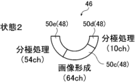
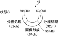
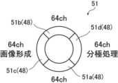
- FIG. 2 is a diagram showing an example of a state of a plurality of ultrasonic transducers driven for image formation and a plurality of ultrasonic transducers subjected to polarization processing at the same time
- FIG. 10 is a diagram showing another example of a state of a plurality of ultrasonic transducers driven for image formation and a plurality of ultrasonic transducers subjected to polarization processing at the same time;
- FIG. 10 is a diagram showing another example of a state of a plurality of ultrasonic transducers driven for image formation and a plurality of ultrasonic transducers subjected to polarization processing at the same time;
- FIG. 10 is a diagram showing another example of a state of a plurality of ultrasonic transducers driven for image formation and a plurality of ultrasonic transducers subjected to polarization processing at the same time;
- FIG. 2 is a diagram showing the flow of diagnostic processing using the ultrasonic endoscope system shown in FIG. 1.
- FIG. FIG. 4 is a diagram showing the procedure of diagnostic steps during diagnostic processing;
- FIG. 4 is a conceptual diagram of an example representing a display mode;
- FIG. 1 is a diagram showing a schematic configuration of an ultrasonic endoscope system 10.
- the ultrasonic endoscope system 10 is used to observe (hereinafter also referred to as ultrasonic diagnosis) the state of an observation target site inside the body of a patient, who is a subject, using ultrasonic waves.
- the site to be observed is a site that is difficult to inspect from the patient's body surface side, such as the gallbladder or pancreas.
- An ultrasonic endoscope system 10 acquires an ultrasonic image and an endoscopic image, and as shown in FIG. It has a mirror processor device 16 , a light source device 18 , a monitor 20 , a water supply tank 21 a , a suction pump 21 b and an operator console 100 .
- the ultrasonic endoscope 12 is an endoscope, and includes an insertion section 22 inserted into a body cavity of a patient, an operation section 24 operated by an operator (user) such as a doctor or a technician, and an insertion section 22. and an ultrasonic transducer unit 46 (see FIGS. 2 and 3) attached to the distal end 40 of the.
- the operator obtains an endoscopic image of the inner wall of the patient's body cavity and an ultrasonic image of the observation target region using the functions of the ultrasonic endoscope 12 .
- an "endoscopic image” is an image obtained by photographing the inner wall of a patient's body cavity using an optical technique.
- An “ultrasonic image” is an image obtained by receiving reflected waves (echoes) of ultrasonic waves transmitted from the body cavity of a patient toward an observation target site and imaging the received signals. Note that the ultrasonic endoscope 12 will be described in detail in a later section.
- the ultrasonic processor device 14 is connected to the ultrasonic endoscope 12 via a universal cord 26 and an ultrasonic connector 32a provided at its end.
- the ultrasonic processor device 14 controls the ultrasonic transducer unit 46 of the ultrasonic endoscope 12 to transmit ultrasonic waves. Further, the ultrasonic processor 14 generates an ultrasonic image by imaging the received signal when the ultrasonic transducer unit 46 receives the reflected wave (echo) of the transmitted ultrasonic wave.
- the ultrasound processor unit 14 will be described in detail in a later section.
- the endoscope processor device 16 is connected to the ultrasonic endoscope 12 via the universal cord 26 and an endoscope connector 32b provided at the end thereof.
- the endoscope processor device 16 acquires image data of a region adjacent to the observation target imaged by the ultrasonic endoscope 12 (more specifically, a solid-state imaging device 86 described later; see FIG. 3), and converts the acquired image data into Predetermined image processing is performed to generate an endoscopic image.
- the "adjacent site to be observed" is a portion of the inner wall of the patient's body cavity that is adjacent to the site to be observed.
- the ultrasound processor 14 and the endoscope processor 16 are composed of two separate devices (computers). However, the present invention is not limited to this, and both the ultrasound processor device 14 and the endoscope processor device 16 may be configured by one device.
- the light source device 18 is connected to the ultrasonic endoscope 12 via the universal cord 26 and a light source connector 32c provided at its end.
- the light source device 18 emits white light or specific wavelength light composed of the three primary colors of red, green, and blue light when imaging a site adjacent to the observation target using the ultrasonic endoscope 12 .
- the light emitted by the light source device 18 propagates through the ultrasonic endoscope 12 through a light guide (not shown) included in the universal cord 26, and passes through the ultrasonic endoscope 12 (specifically, an illumination window 88 to be described later: 2).
- an illumination window 88 to be described later: 2 the adjacent site to be observed is illuminated by the light from the light source device 18 .
- the monitor 20 is connected to the ultrasound processor device 14 and the endoscope processor device 16, and displays the ultrasound images generated by the ultrasound processor device 14 and the ultrasound images generated by the endoscope processor device 16.
- Display endoscopic images As a display method for the ultrasonic image and the endoscopic image, either one of the images may be switched and displayed on the monitor 20, or both images may be displayed simultaneously. Display modes for ultrasonic images and endoscopic images will be described later. In this embodiment, an ultrasonic image and an endoscopic image are displayed on the single monitor 20, but a monitor for displaying the ultrasonic image and a monitor for displaying the endoscopic image are provided separately. good too. Further, the ultrasonic image and the endoscopic image may be displayed in a display form other than the monitor 20, for example, in a display form of a terminal carried by the operator.
- the operator console 100 is a device provided for the operator to input necessary information for ultrasonic diagnosis and to instruct the ultrasonic processor device 14 to start ultrasonic diagnosis.
- the operator console 100 includes, for example, a keyboard, mouse, trackball, touch pad, touch panel, and the like.
- the CPU (control circuit) 152 (see FIG. 4) of the ultrasonic processor device 14 controls each part of the device (for example, a receiving circuit 142 and a transmitting circuit 144 which will be described later) in accordance with the contents of the operation. Control.
- the operator before starting the ultrasonic diagnosis, the operator provides examination information (for example, examination order information including date and order number, and patient information including patient ID and patient name). ) on the console 100 .
- examination information for example, examination order information including date and order number, and patient information including patient ID and patient name.
- the CPU 152 of the ultrasonic processor unit 14 executes ultrasonic diagnosis based on the inputted examination information.
- Each section of the ultrasonic processor unit 14 is controlled.
- the operator can set various control parameters on the console 100 when performing ultrasonic diagnosis. Control parameters include, for example, the result of selection between live mode and freeze mode, the set value of display depth (depth), and the result of selection of ultrasonic image generation mode.
- the "live mode” is a mode in which ultrasonic images (moving images) obtained at a predetermined frame rate are sequentially displayed (real-time display).
- the “freeze mode” is a mode in which a one-frame image (still image) of an ultrasound image (moving image) generated in the past is read out from the cine memory 150 described later and displayed.
- the B mode is a mode for displaying a tomographic image by converting the amplitude of an ultrasonic echo into luminance.
- the CF mode is a mode in which average blood flow velocity, flow fluctuation, flow signal intensity, flow power, etc. are mapped in various colors and displayed superimposed on a B-mode image.
- the PW mode is a mode for displaying the velocity of an ultrasonic echo source (for example, blood flow velocity) detected based on the transmission and reception of pulse waves.
- ultrasonic image generation mode is merely an example, and modes other than the three types of modes described above, such as A (Amplitude) mode, M (Motion) mode, contrast mode, etc., may be further included. However, a mode for obtaining Doppler images may also be included.
- FIG. 2 is an enlarged plan view showing the distal end portion of the insertion portion 22 of the ultrasonic endoscope 12 and its surroundings.
- FIG. 3 is a cross-sectional view showing a cross section of the distal end portion 40 of the insertion portion 22 of the ultrasonic endoscope 12 taken along the II cross section shown in FIG.
- the ultrasonic endoscope 12 has the insertion section 22 and the operation section 24 as described above.
- the insertion portion 22 includes a distal end portion 40, a curved portion 42, and a flexible portion 43 in order from the distal end side (free end side), as shown in FIG.
- the distal end portion 40 is provided with an ultrasonic observation section 36 and an endoscope observation section 38 as shown in FIG.
- an ultrasonic transducer unit 46 having a plurality of ultrasonic transducers 48 is arranged in the ultrasonic observation section 36 .
- the treatment instrument lead-out port 44 serves as an outlet for a treatment instrument (not shown) such as forceps, a puncture needle, or a high-frequency scalpel.
- the treatment instrument lead-out port 44 also serves as a suction port for sucking substances such as blood and body waste.
- the bending portion 42 is a portion that is continuous with the proximal end side (the side opposite to the side where the ultrasonic transducer unit 46 is provided) from the distal end portion 40, and is bendable.
- the flexible portion 43 is a portion that connects the bending portion 42 and the operation portion 24 , has flexibility, and is provided in an elongated state.
- a plurality of ducts for supplying air and water and a plurality of ducts for suction are formed inside each of the insertion portion 22 and the operation portion 24, a treatment instrument channel 45 is formed, one end of which communicates with the treatment instrument outlet 44.
- the ultrasonic observation section 36, the endoscope observation section 38, the water supply tank 21a and the suction pump 21b, and the operation section 24 will be described in detail.
- the ultrasonic observation section 36 is a section provided for acquiring an ultrasonic image, and is arranged on the distal end side of the distal section 40 of the insertion section 22 .
- the ultrasound observation unit 36 includes an ultrasound transducer unit 46, a plurality of coaxial cables 56, and an FPC (Flexible Printed Circuit) 60, as shown in FIG.
- the ultrasonic transducer unit 46 corresponds to an ultrasonic probe (probe), and ultrasonic waves are generated using an ultrasonic transducer array 50 in which a plurality of ultrasonic transducers 48, which will be described later, are arranged in a patient's body cavity.
- the ultrasonic transducer unit 46 is of a convex type, and transmits ultrasonic waves radially (in an arc).
- the type (model) of the ultrasonic transducer unit 46 is not particularly limited to this, and other types may be used as long as they can transmit and receive ultrasonic waves, such as sector type, linear type and radial type. etc.
- the ultrasonic transducer unit 46 is configured by laminating a backing material layer 54, an ultrasonic transducer array 50, an acoustic matching layer 74, and an acoustic lens 76, as shown in FIG.
- the ultrasonic transducer array 50 may be configured by arranging a plurality of ultrasonic transducers 48 in a two-dimensional array.
- Each of the N ultrasonic transducers 48 is configured by arranging electrodes on both sides of a single-crystal transducer, which is a piezoelectric element.
- Crystal lithium niobate, lead magnesium niobate (PMN), lead magnesium niobate-lead titanate (PMN-PT), lead zinc niobate (PZN), lead zinc niobate-titanate Any one of lead (PZN-PT), lead indium niobate (PIN), lead titanate (PT), lithium tantalate, langasite, and zinc oxide is used.
- the electrodes consist of individual electrodes (not shown) individually provided for each of the plurality of ultrasonic transducers 48 and a transducer ground (not shown) common to the plurality of ultrasonic transducers 48 .
- the electrodes are also electrically connected to the ultrasound processor unit 14 via the coaxial cable 56 and the FPC 60 .
- the ultrasonic transducer 48 needs to be driven (vibrated) at a relatively high frequency of 7 MHz to 8 MHz for the purpose of acquiring an ultrasonic image of the body cavity of the patient. Therefore, the thickness of the piezoelectric element forming the ultrasonic transducer 48 is designed to be relatively thin, for example, 75 ⁇ m to 125 ⁇ m, preferably 90 ⁇ m to 110 ⁇ m.
- a diagnostic drive pulse which is a pulsed drive voltage, is supplied to each ultrasonic transducer 48 as an input signal (transmission signal) from the ultrasonic processor 14 through the coaxial cable 56 .
- the piezoelectric element expands and contracts to drive (vibrate) the ultrasonic transducer 48 .
- a pulsed ultrasonic wave is output from the ultrasonic transducer 48 .
- the amplitude of the ultrasonic waves output from the ultrasonic transducer 48 has a magnitude corresponding to the intensity (output intensity) when the ultrasonic transducer 48 outputs the ultrasonic waves.
- the output intensity is defined as the magnitude of the sound pressure of the ultrasonic waves output from the ultrasonic transducer 48 .
- each ultrasonic transducer 48 When each ultrasonic transducer 48 receives a reflected ultrasonic wave (echo), it vibrates (drives) accordingly, and the piezoelectric element of each ultrasonic transducer 48 generates an electric signal. This electrical signal is output from each ultrasonic transducer 48 toward the ultrasonic processor 14 as an ultrasonic reception signal. At this time, the magnitude (voltage value) of the electric signal output from the ultrasonic transducer 48 corresponds to the reception sensitivity when the ultrasonic transducer 48 receives ultrasonic waves.
- the reception sensitivity is defined as the ratio of the amplitude of the electric signal output by the ultrasonic transducer 48 after receiving the ultrasonic wave to the amplitude of the ultrasonic wave transmitted by the ultrasonic transducer 48 .
- the scanning range along the curved surface on which the ultrasonic transducer array 50 is arranged for example, Ultrasonic waves are scanned in a range of about several tens of millimeters from the center of curvature of the curved surface, and the ultrasonic transducer array 50 that is not scanned is subjected to polarization processing.
- the maximum simultaneous numerical aperture of the transmission circuit 144 is M (eg, 64), and N (M ⁇ N, eg, 128) ultrasonic transducers.
- an M:N (eg, 1:2) multiplexer 140 is used.
- M is 64 and N is 128,
- No. 1 of the transmission circuit 144 is connected to Nos. 1 and 65 of the ultrasonic transducers 48, and No. 2 of the transmission circuit 144 is connected to the ultrasonic transducer.
- the last number 64 of the transmission circuit 144 is connected to numbers 64 and 128 of the ultrasonic transducer 48 .
- ultrasonic transducers 48 1 and 65 are connected to the same channel 1 of the pulser 158 of the transmission circuit 144, they cannot be driven at the same time.
- ultrasonic transducers 48 2 and 66 followed by ultrasonic transducers 48 p and (p+64), and finally ultrasonic transducers 48 64 and 128, They cannot be driven at the same time.
- the remaining (M ⁇ m) channels of the pulser 158 are used to polarize the (M ⁇ m) ultrasonic transducers 48 that are not driven.
- the 32 ultrasonic transducers 48 numbered 1 to 32 are driven to acquire an ultrasonic image, that is, to draw an image
- the 32 ultrasonic transducers 48 numbered 65 to 96 are connected to the same pulser 158 and cannot be driven.
- either the 32 ultrasonic transducers 48 numbered 33 to 64 or the 32 ultrasonic transducers 48 numbered 97 to 128 can be selected by the multiplexer 140 for polarization processing. . Therefore, while the 32 ultrasonic transducers 48 numbered 1 to 32 selected by the multiplexer 140 are being driven for imaging, the number 33 to 64 or number 97 selected by the multiplexer 140 is driven. The 32 ultrasonic transducers 48 of Nos. 128 to 128 can be subjected to polarization treatment.
- a driven transducer the ultrasonic transducer 48
- a driven transducer is supplied with a drive voltage.
- m drive target transducers are driven, and ultrasonic waves are output from each of the drive target transducers in the open channel.
- the ultrasonic waves output from the m drive target transducers are immediately synthesized, and the synthesized wave (ultrasonic beam) is transmitted toward the observation target region.
- each of the m drive target transducers receives the ultrasonic waves (echoes) reflected by the observation target site, and outputs an electric signal (reception signal) corresponding to the reception sensitivity at that time.
- the multiplexer 140 selects an aperture channel for polarization, thereby obtaining an ultrasonic image from among the N ultrasonic transducers 48.
- (M ⁇ m) ultrasonic transducers 48 (hereinafter also referred to as “polarized transducers”) that are not used are supplied with a polarization voltage different from the driving voltage of the driven transducers 48, A polarization process is performed.
- the polarization processing of the ultrasonic transducer 48 will be described in detail in a later section.
- the series of image rendering steps for obtaining an ultrasonic image (that is, supply of drive voltage to the transducer to be driven, transmission and reception of ultrasonic waves, and output of electrical signals) is performed by N ultrasonic transducers.
- the position of the transducer to be driven in 48 may be shifted one by one (by one ultrasonic transducer 48) and repeated.
- the series of polarization processing steps for the polarization processing and the positions of the polarization target transducers among the N ultrasonic transducers 48 are shifted one by one (by one ultrasonic transducer 48). may be repeated.
- the above-described series of image rendering processes is performed by centering the ultrasonic transducer 48 located at one end of the N ultrasonic transducers 48 and m pieces on both sides thereof. It starts with the oscillator to be driven.
- the series of polarization processing steps also starts from (M ⁇ m) number of polarization object oscillators corresponding to the m number of drive object oscillators.
- the series of image rendering steps described above is repeated every time the position of the transducer to be driven shifts due to switching of the aperture channel by the multiplexer 140 .
- the series of polarization processing steps described above is also repeated each time the position of the polarization target vibrator corresponding to the drive target vibrator shifts due to the switching of the open channel by the multiplexer 140 .
- the above series of image rendering processes reach m driven transducers on both sides of the ultrasonic transducer 48 located at the other end of the N ultrasonic transducers 48. This is repeated N times in total.
- the above series of polarization processing steps are also repeated N times in total until reaching (M ⁇ m) number of polarization object transducers corresponding to m number of drive object transducers on both sides of the ultrasonic transducer 48 at the other end. implemented. In this way, the N ultrasonic transducers 48 can be evenly used and the N ultrasonic transducers 48 can be equally polarized to obtain an ultrasonic image.
- the backing material layer 54 supports each ultrasonic transducer 48 of the ultrasonic transducer array 50 from the back side. In addition, the backing material layer 54 attenuates the ultrasonic waves propagated to the backing material layer 54 side among the ultrasonic waves emitted from the ultrasonic transducer 48 or the ultrasonic waves (echoes) reflected at the observation target site. have a function.
- the backing material is made of a rigid material such as hard rubber, and an ultrasonic damping material (ferrite, ceramics, etc.) is added as necessary.
- the acoustic matching layer 74 is overlaid on the ultrasound transducer array 50 and provided for acoustic impedance matching between the patient's body and the ultrasound transducers 48 .
- the acoustic matching layer 74 By providing the acoustic matching layer 74, it is possible to increase the transmittance of ultrasonic waves.
- the material of the acoustic matching layer 74 various organic materials whose acoustic impedance value is closer to that of the patient's human body than the piezoelectric element of the ultrasonic transducer 48 can be used.
- Specific examples of materials for the acoustic matching layer 74 include epoxy resin, silicon rubber, polyimide, and polyethylene.
- the acoustic lens 76 superimposed on the acoustic matching layer 74 is for converging the ultrasonic waves emitted from the ultrasonic transducer array 50 toward the site to be observed.
- the acoustic lens 76 is made of, for example, silicon-based resin (millable type silicon rubber (HTV rubber), liquid silicon rubber (RTV rubber), etc.), butadiene-based resin, polyurethane-based resin, or the like. , alumina or silica are mixed.
- the FPC 60 is electrically connected to electrodes provided on each ultrasonic transducer 48 .
- Each of the plurality of coaxial cables 56 is wired to the FPC 60 at one end thereof.
- each of the plurality of coaxial cables 56 is connected at the other end (the side opposite to the FPC 60 side). It is electrically connected to the ultrasonic processor device 14 .
- the ultrasonic endoscope 12 may include an endoscope-side memory 58 (see FIG. 4).
- the endoscope-side memory 58 stores drive times of the plurality of ultrasonic transducers 48 during ultrasonic diagnosis. Strictly speaking, the endoscope-side memory 58 stores the accumulated driving time of the drive target transducer among the plurality of ultrasonic transducers 48 . Note that the endoscope-side memory 58 may further store the accumulated processing time of the polarization processing of the polarization target transducer among the plurality of ultrasonic transducers 48 .
- the accumulated driving time and the accumulated processing time are defined as the accumulated drive time and the accumulated processing time, but the present invention is not limited to this.
- the time during which the voltage is supplied may be used as the cumulative processing time.
- the CPU 152 of the ultrasonic processor device 14 accesses the endoscope-side memory 58, and the accumulated data stored in the endoscope-side memory 58 It is possible to read the driving time and also the cumulative processing time.
- the CPU 152 of the ultrasound processor 14 also rewrites the cumulative driving time and the cumulative processing time stored in the endoscope-side memory 58 to default values, and changes the cumulative driving time, Furthermore, when the cumulative processing time changes, the cumulative drive time is updated to a new cumulative processing time.
- the endoscopic observation section 38 is a portion provided for acquiring an endoscopic image, and is arranged on the distal end portion 40 of the insertion section 22 closer to the proximal side than the ultrasonic observation section 36 .
- the endoscope observation section 38 is composed of an observation window 82, an objective lens 84, a solid-state imaging device 86, an illumination window 88, a cleaning nozzle 90, a wiring cable 92, and the like, as shown in FIGS.
- the observation window 82 is attached to the distal end portion 40 of the insertion section 22 so as to be inclined with respect to the axial direction (longitudinal axis direction of the insertion section 22).
- the light incident through the observation window 82 and reflected by the portion adjacent to the observation object is imaged on the imaging surface of the solid-state imaging device 86 by the objective lens 84 .
- the solid-state imaging device 86 photoelectrically converts the reflected light from the observation target adjacent region that has passed through the observation window 82 and the objective lens 84 and is imaged on the imaging surface, and outputs an imaging signal.
- a CCD Charge Coupled Device
- CMOS Complementary Metal Oxide Semiconductor
- a captured image signal output by the solid-state imaging device 86 is transmitted to the endoscope processor device 16 via the universal cord 26 via a wiring cable 92 extending from the insertion section 22 to the operation section 24 .
- the illumination windows 88 are provided on both sides of the observation window 82 .
- An output end of a light guide (not shown) is connected to the illumination window 88 .
- the light guide extends from the insertion portion 22 to the operation portion 24 and its incident end is connected to the light source device 18 connected via the universal cord 26 .
- Illumination light emitted by the light source device 18 travels through the light guide and is irradiated from the illumination window 88 toward the site adjacent to the observation target.
- the cleaning nozzle 90 is a jet hole formed in the distal end portion 40 of the insertion portion 22 for cleaning the surfaces of the observation window 82 and the illumination window 88 . and is jetted toward the illumination window 88 .
- the cleaning liquid ejected from the cleaning nozzle 90 is water, particularly degassed water.
- the cleaning liquid is not particularly limited, and may be another liquid such as normal water (non-deaerated water).
- the water supply tank 21a is a tank for storing degassed water, and is connected to the light source connector 32c by an air/water supply tube 34a.
- the degassed water is used as the cleaning liquid jetted from the cleaning nozzle 90 .
- the suction pump 21b sucks the aspirate (including the degassed water supplied for washing) inside the body cavity through the treatment instrument outlet 44 .
- the suction pump 21b is connected to the light source connector 32c through a suction tube 34b.
- the ultrasonic endoscope system 10 may include an air supply pump or the like that supplies air to a predetermined air supply destination.
- a treatment instrument channel 45 and an air/water supply conduit are provided in the insertion section 22 and the operation section 24 .
- the treatment instrument channel 45 communicates between the treatment instrument insertion port 30 and the treatment instrument outlet port 44 provided in the operation section 24 .
- the treatment instrument channel 45 is connected to a suction button 28b provided on the operation section 24 .
- the suction button 28b is connected to the treatment instrument channel 45 and also to the suction pump 21b.
- One end of the air/water supply conduit communicates with the cleaning nozzle 90 , and the other end thereof is connected to the air/water supply button 28 a provided on the operation unit 24 .
- the air/water supply button 28a is connected to the water supply tank 21a in addition to the air/water supply conduit.
- the operation unit 24 is a portion operated by the operator at the start of ultrasonic diagnosis, during diagnosis, at the end of diagnosis, etc., and one end of a universal cord 26 is connected to one end of the operation unit 24 .
- the operation unit 24 also has an air/water supply button 28a, a suction button 28b, a pair of angle knobs 29, and a treatment instrument insertion opening (forceps opening) 30, as shown in FIG.
- the bending portion 42 is remotely operated to bend and deform. This deformation operation enables the distal end portion 40 of the insertion portion 22 provided with the ultrasonic observation portion 36 and the endoscope observation portion 38 to be directed in a desired direction.
- the treatment instrument insertion port 30 is a hole formed for inserting a treatment instrument (not shown) such as forceps, and communicates with the treatment instrument outlet 44 via a treatment instrument channel 45 .
- the treatment instrument inserted into the treatment instrument insertion port 30 is introduced into the body cavity from the treatment instrument outlet port 44 after passing through the treatment instrument channel 45 .
- the air/water supply button 28a and the suction button 28b are two-stage switching push buttons, and are operated to switch opening and closing of the channels provided inside the insertion section 22 and the operation section 24, respectively.
- the ultrasonic processor device 14 causes m ultrasonic transducers 48 (more specifically, elements to be driven) among the N ultrasonic transducers 48 of the ultrasonic transducer unit 46 to transmit and receive ultrasonic waves, and Received signals output from the same m number of ultrasonic transducers 48 (that is, elements to be driven) during ultrasonic reception are imaged to generate an ultrasonic image.
- the ultrasound processor device 14 also displays the generated ultrasound image on the monitor 20 . Furthermore, in the present embodiment, the ultrasound processor device 14 is used to generate ultrasound images of the N ultrasound transducers 48 at the same time, and then is not used to generate ultrasound images.
- the ultrasound processor 14 includes a multiplexer 140, a receiving circuit 142, a transmitting circuit 144, an A/D converter 146, an ASIC (Application Specific Integrated Circuit) 148, a cine memory 150, and a CPU (Central Processing Unit). 152, and a DSC (Digital Scan Converter) 154.
- the receiving circuit 142 and the transmitting circuit 144 are electrically connected to the ultrasonic transducer array 50 of the ultrasonic endoscope 12 .
- the multiplexer 140 selects up to m driven transducers from among the N ultrasound transducers 48 for generation of an ultrasound image and opens their channels. First, a maximum (N ⁇ m) number of transducers to be driven that are not transducers to be driven are selected from among the N ultrasonic transducers 48, and the channels thereof are opened for polarization.
- the transmission circuit 144 includes an FPGA (Field Programmable Gate Array), a pulser (pulse generation circuit 158), SW (switch), etc., and is connected to the MUX (multiplexer 140). Note that an ASIC (application specific integrated circuit) may be used instead of the FPGA. In order to transmit ultrasonic waves from the ultrasonic transducer unit 46, the transmission circuit 144 applies a driving voltage for transmitting ultrasonic waves to the transducers to be driven selected by the multiplexer 140 according to control signals sent from the CPU 152.
- FPGA Field Programmable Gate Array
- a pulser pulse generation circuit 158
- SW switch
- ASIC application specific integrated circuit
- this is a circuit that supplies a polarization voltage for performing polarization processing to the polarization target oscillator selected by the multiplexer 140 .
- the drive voltage is a pulsed voltage signal (transmission signal) and is applied to the electrodes of the vibrator to be driven via the universal cord 26 and coaxial cable 56 .
- the polarization voltage is also a pulsed voltage signal (transmission signal) and is applied to the electrodes of the transducer to be driven via the universal cord 26 and coaxial cable 56 .
- the transmission circuit 144 has a pulse generation circuit 158 that generates transmission signals based on control signals.
- a transmission signal for generating a sound wave is generated and supplied to the plurality of ultrasonic transducers 48 to be driven, and a transmission signal for polarization processing is generated and sent to the plurality of ultrasonic transducers 48 to be polarized. supply. That is, under the control of the CPU 152, the transmission circuit 144 uses the pulse generation circuit 158 to generate a first transmission signal having a drive voltage for performing ultrasonic diagnosis.
- the same pulse generation circuit 158 as that used to generate the first transmission signal is used to generate a second transmission signal having a polarization voltage for performing polarization processing.
- the signal waveform of the first transmission signal for ultrasonic wave generation for ultrasonic diagnosis is different from the signal waveform of the second transmission signal for polarization processing for performing the polarization processing.
- different signal waveforms mean that at least one of the frequency, voltage, and wave number of the signal waveforms is different.
- the receiving circuit 142 is a circuit that receives an electrical signal, that is, a received signal, output from the transducer to be driven that has received an ultrasonic wave (echo). Further, the receiving circuit 142 amplifies the received signal received from the ultrasonic transducer 48 according to the control signal sent from the CPU 152 and transfers the amplified signal to the A/D converter 146 .
- the A/D converter 146 is connected to the receiving circuit 142 , converts the received signal received from the receiving circuit 142 from an analog signal to a digital signal, and outputs the converted digital signal to the ASIC 148 .
- the ASIC 148 is connected to the A/D converter 146, and as shown in FIG. constitutes
- hardware circuits such as the ASIC 148 perform the functions described above (specifically, the phase matching unit 160, the B mode image generation unit 162, the PW mode image generation unit 164, the CF mode image generation unit 166 and Although the memory controller 151) is implemented, it is not limited to this.
- the above functions may be realized by cooperation between a central processing unit (CPU) and software (computer program) for executing various data processing.
- the phase matching unit 160 performs a process of applying a delay time to the received signal (received data) digitized by the A/D converter 146 and performing phasing addition (adding after matching the phase of the received data). do.
- a sound ray signal in which the focus of the ultrasonic echo is narrowed is generated by the phasing and addition processing.
- the B-mode image generation unit 162, the PW-mode image generation unit 164, and the CF-mode image generation unit 166 select the driven transducer among the plurality of ultrasonic transducers 48 when the ultrasonic transducer unit 46 receives ultrasonic waves. generates an ultrasound image based on the electrical signal output by (strictly speaking, the audio signal generated by phasing and adding the received data).
- the B-mode image generation unit 162 is an image generation unit that generates a B-mode image, which is a tomographic image of the inside (inside the body cavity) of the patient.
- the B-mode image generator 162 corrects the attenuation caused by the propagation distance according to the depth of the reflection position of the ultrasonic waves by STC (Sensitivity Time Gain Control) for the sequentially generated sound ray signals.
- the B-mode image generation unit 162 also performs envelope detection processing and log (logarithmic) compression processing on the corrected sound ray signal to generate a B-mode image (image signal).
- the PW mode image generator 164 is an image generator that generates an image that displays the blood flow velocity in a predetermined direction.
- the PW mode image generation unit 164 extracts frequency components by performing a fast Fourier transform on a plurality of sound ray signals in the same direction among the sound ray signals sequentially generated by the phase matching unit 160 . After that, the PW mode image generator 164 calculates the blood flow velocity from the extracted frequency components, and generates a PW mode image (image signal) displaying the calculated blood flow velocity.
- the CF mode image generation unit 166 is an image generation unit that generates an image that displays blood flow information in a predetermined direction.
- the CF-mode image generating unit 166 generates an image signal indicating information about blood flow by obtaining the autocorrelation of a plurality of sound ray signals in the same direction among the sound ray signals sequentially generated by the phase matching unit 160. . After that, the CF-mode image generation unit 166 generates a CF-mode image (image signal ).
- the memory controller 151 stores the image signal generated by the B-mode image generator 162 , PW-mode image generator 164 or CF-mode image generator 166 in the cine memory 150 .
- the DSC 154 is connected to the ASIC 148, and converts the image signal generated by the B-mode image generator 162, PW-mode image generator 164, or CF-mode image generator 166 into an image signal conforming to a normal television signal scanning method. (raster conversion), and the image signal is output to the monitor 20 after being subjected to various necessary image processing such as gradation processing.
- the cine memory 150 has a capacity for accumulating image signals for one frame or several frames.
- the image signal generated by the ASIC 148 is output to the DSC 154 and also stored in the cine memory 150 by the memory controller 151 .
- the memory controller 151 reads the image signal stored in the cine memory 150 and outputs it to the DSC 154 .
- an ultrasonic image (still image) based on the image signal read from the cine-memory 150 is displayed on the monitor 20 .
- the CPU 152 functions as a control section (control circuit) that controls each section of the ultrasonic processor device 14, and is connected to the receiving circuit 142, the transmitting circuit 144, the A/D converter 146, and the ASIC 148 to control these devices. Control. More specifically, the CPU 152 is connected to the operator console 100 and controls each part of the ultrasonic processor device 14 according to examination information, control parameters, etc. input from the operator console 100 . Further, when the ultrasonic endoscope 12 is connected to the ultrasonic processor device 14 via the ultrasonic connector 32a, the CPU 152 automatically recognizes the ultrasonic endoscope 12 by a method such as PnP (Plug and Play). do. After that, the CPU 152 accesses the endoscope-side memory 58 of the ultrasonic endoscope 12 and reads the cumulative driving time and the cumulative processing time stored in the endoscope-side memory 58 .
- PnP Plug and Play
- the CPU 152 accesses the endoscope-side memory 58 at the end of the ultrasonic diagnosis, and uses the accumulated drive time and the accumulated processing time stored in the endoscope-side memory 58 as the ultrasonic diagnosis performed immediately before. Update to the value added by the required time.
- the ultrasonic endoscope 12 stores the cumulative driving time and the cumulative processing time, but the present invention is not limited to this. The time and cumulative processing time may be stored for each ultrasonic endoscope 12 .
- the CPU 152 may control the multiplexer 140 to select all the ultrasonic transducers 48 other than the transducers to be driven as the transducers to be polarized.
- control may be performed to select the polarization target vibrator according to the accumulated driving time read out from 48 .
- the polarization drive pulse which is the second transmission signal
- the transmission circuit 144 that generates the diagnosis drive pulse, which is the first transmission signal for acquiring an ultrasonic image.
- the transmission circuit 144 has the same circuit configuration as an existing transmission circuit that does not have a new circuit configuration for generating the polarization drive pulse.
- the transmission circuit 144 has a settable voltage range in which at least two drive voltages, the image drive voltage of the diagnostic drive pulse and the polarization drive voltage of the polarization drive pulse, can be set.
- the driving voltage for imaging When acquiring an ultrasound image, set the driving voltage for imaging within the settable voltage range, and when performing polarization processing, set the driving voltage for imaging and the driving voltage for polarization that is different from the driving voltage for imaging within the same settable voltage range. set.
- the polarization drive voltage is preferably set to a voltage higher than the image drive voltage, and more preferably set to a higher voltage within the settable voltage range. Most preferably set.
- the polarization drive pulse (main lobe) is preferably a drive pulse in a frequency band different from the probe frequency band of the diagnosis drive pulse. Therefore, it can be said that the drive voltage applied to the ultrasonic transducers 48 during the polarization process is preferably higher than the drive voltage applied to the ultrasonic transducers 48 during acquisition of the ultrasonic image.
- the polarization drive pulse wave applied to the ultrasonic transducer 48 during the polarization process is generated by the same transmission circuit 144 as the diagnostic drive pulse wave applied to the ultrasonic transducer 48 during acquisition of the ultrasonic image, It can be said that it is preferable that the drive pulse wave has a different polarization drive voltage within the same settable voltage range as the image drive pulse wave and a frequency different from the probe frequency band for acquiring the ultrasonic image.
- the present invention has an existing transmission circuit configuration, uses the same transmission circuit 144 for driving pulse output as that for acquiring an ultrasonic image, and uses the same setting as the diagnostic driving pulse for acquiring an ultrasonic image.
- the ultrasonic transducer of the ultrasonic endoscope 12 simultaneously outputs a driving pulse for polarization having a driving voltage within the possible voltage range and a frequency different from the probe frequency band at the same time as the driving pulse for diagnosis, and simultaneously acquires an ultrasonic image. It can be said that the polarization treatment of 48 is performed.
- the magnitude of the drive voltage (voltage value or potential) of the polarization drive pulse is within the settable voltage range of the transmission circuit 144.
- the CPU 152 sets an appropriate value that satisfies the conditions for obtaining the effect of repolarization according to the specifications of the ultrasonic transducer 48 (more specifically, the thickness and material of the ultrasonic transducer 48).
- the supply time of the driving voltage of the driving pulse for polarization is determined by the CPU 152 according to the specifications of the ultrasonic transducer 48 (more specifically, the thickness and material of the ultrasonic transducer 48). It is supposed to be set to an appropriate value that satisfies Thereafter, the CPU 152 performs polarization processing based on the set values.
- the CPU (control circuit) 152 applies a diagnostic drive pulse (first pulse) to each of the plurality of first ultrasonic transducers 48 that generate ultrasonic waves for acquiring ultrasonic images. It controls the transmission circuit 144 (pulse generation circuit 158) to generate a transmission signal). At the same time, the CPU (control circuit) 152 uses different polarization signals within the same settable voltage range as the diagnostic driving pulse to perform polarization processing of the plurality of second ultrasonic transducers 48 that are not generating ultrasonic waves.
- the diagnostic driving pulse is applied to the plurality of first ultrasonic transducers 48, and the diagnostic driving pulse causes the plurality of first ultrasonic transducers 48 to generate ultrasonic waves, which are polarized.
- a driving pulse for polarization is applied to the plurality of second ultrasonic transducers 48, and the plurality of second ultrasonic transducers 48 is polarized by the driving pulse for polarization.
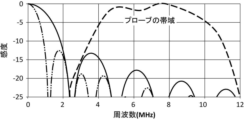
- 5A and 5B are graphs showing an example of the drive waveform of the polarization drive pulse transmitted from the transmission circuit shown in FIG. 4, and graphs showing the relationship between the sensitivity and frequency of the drive waveform.
- the drive waveform shown in FIG. 5A is a unipolar single wave waveform with a frequency of 1.25 MHz.
- the driving waveform of the polarizing driving pulse is not particularly limited. It is preferable to perform the polarization processing of the ultrasonic transducer 48 using the ultrasonic transducer 48 .
- the probe frequency band for acquiring ultrasound images is about 2.7 MHz to about 11.7 MHz, as indicated by the dashed line.
- the band of the main lobe of the drive waveform of the polarization drive pulse indicated by the solid line is about 2.3 MHz or less. That is, the band characteristics of the frequency of the driving pulse for polarization and the band characteristics of the frequency of the driving pulse for diagnosis do not overlap at a sensitivity level of -20 dB or higher.
- the frequency band of the main lobe and the probe frequency band indicated by the dashed line do not overlap at a sensitivity level of -20 dB or more. preferable.
- the frequency band of the main lobe is preferably lower than the probe frequency band at a sensitivity level of -20 dB or higher.
- the upper limit temperature of the distal end portion of the ultrasonic endoscope 12 inserted into the body cavity of the subject is strictly limited so as not to affect the body cavity, etc., and it is necessary to prevent the temperature from rising.
- the driving pulse for polarization (main lobe) is transmitted outside the probe frequency band, the input energy to the ultrasonic transducer 48 is reduced and the temperature rise is suppressed. Further, since the area outside the probe frequency band is outside the resonance band in which the ultrasonic transducer 48 resonates, even if the polarization drive pulse (main lobe) is applied to the ultrasonic transducer 48, the output sound pressure also becomes small.
- the drive waveform of the polarizing drive pulse shown in FIG. 5B in addition to the main lobe, there are also one or more side polarizers shown by solid lines, and four side polarizers in the example shown in FIG. It can be seen that lobes are generated.
- the maximum sensitivity of these sidelobes within the probe frequency band are preferably all less than -10 dB, and the average sensitivity of these sidelobes is preferably less than -20 dB, as shown in FIG. 5B.
- the driving waveform of the polarizing driving pulse is not particularly limited, and may be a bipolar waveform as shown in FIG. 6A, but may be a unipolar waveform as shown in FIG. 5A. preferable.
- the reason for this is that, as in the frequency characteristics of the driving waveform shown in FIG. This is because the unipolar waveform is lower than the bipolar waveform. Therefore, by making the transmission waveform a unipolar waveform as shown in FIG. 5A, not only the main lobe but also the harmonic components can be suppressed, and a higher effect can be expected.
- the polarizing drive pulse shown in FIG. 7A has a drive waveform including two pulse waves of the polarizing drive pulse shown in FIG. 5A.
- FIG. 7B shows the frequency characteristics of the drive waveform of the polarization drive pulse shown in FIG. 7A.
- the frequency characteristics of the driving waveform shown in FIG. 7B are different from the frequency characteristics of the driving waveform shown in FIG. 5B in the waveform of the main lobe, but the waveform of the side lobe does not change significantly. Further, as shown in FIG.
- the transmission circuit 144 can output a plurality of unipolar waveforms as the polarization drive pulse with the interval of the waveforms being the minimum number of clocks defined in the ultrasonic processor device 14 .
- the reason for this is that although it is optimal to apply a DC voltage for polarization processing, DC voltage cannot be transmitted when using the transmission circuit 144 having an existing transmission circuit configuration as in the present invention. .
- the minimum and maximum time widths are determined depending on the type of pulser (pulse generation circuit 158) of the transmission circuit 144 of the ultrasonic processor device 14 used in the ultrasonic endoscope system 10.
- FIG. Therefore, as the minimum time width, the time of the minimum number of clocks specified in the transmission circuit 144 is used, the minimum time width is interposed between a plurality of unipolar waveforms, and a polarized waveform close to a DC voltage is obtained. A high repolarization effect can be expected.
- the minimum time width of the two unipolar pulse waveforms, that is, the strongest pulse width is determined by the specifications of the pulser (pulse generation circuit 158) of the transmission circuit 144.
- FIGS. 8A and 8B are graphs showing examples of drive waveforms of diagnostic drive pulses transmitted from the transmission circuit shown in FIG. 4, and graphs showing the relationship between the sensitivity and frequency of the drive waveforms.
- FIG. 8A is a bipolar single-wave waveform with a center frequency of 6 MHz.
- FIG. 8B shows the frequency characteristic of the drive waveform of the diagnostic drive pulse. From the above, it is preferable that the drive waveform (transmission waveform) of the polarization drive pulse and the drive waveform (transmission waveform) of the diagnostic drive pulse are different. More specifically, at least one of voltage, frequency, and wave number is different. is preferred.
- an ultrasonic system is miniaturized by limiting the simultaneous transmission numerical aperture (the number of pulsar channels), that is, by limiting the number of ultrasonic transducers that simultaneously transmit ultrasonic waves.
- the multiple elements are driven through a multiplexer 140 functioning as a switch.
- high-end machines achieve improved image quality by increasing the number of pulsar channels. That is, in the example shown in FIG. 9, the number of channels of the elements (ultrasonic transducers 48) of the probe (ultrasonic transducer unit 46) is 256 channels (ch).
- the element group 49 consisting of the 256 ch elements 48 of the probe 46 is divided into four element groups 49a to 49d consisting of 64 ch elements 48, and the multiplexer 140, An element group 49a composed of one divided group of 64ch elements 48 is selected, each element 48 of the element group 49a is connected to each of the 64ch elements of the pulser 158, and the 64ch elements 48 are simultaneously opened and driven for transmission. , to acquire an ultrasound image.
- illustration of each element (ultrasonic transducer) 48 in the element group is omitted.
- the 64ch elements 48 of the remaining three element groups 49b to 49d are not driven and are not used for acquiring an ultrasonic image.
- the driving of each element 48 of the element group 49a is stopped, and the 64ch elements 48 of the next element group 49b are driven.
- the elements 48 of the element groups 49c and 49d can be sequentially driven.
- three element groups out of the four element groups 49a to 49d are not driven, so the example shown in FIG. 9 is over-specified.
- the pulser 158 on the system side has 256 channels, all the elements 48 can be driven, so the multiplexer 140 is unnecessary. Therefore, when the number of channels of the element 48 of the probe 46 is large, it is conceivable to increase the number of channels of the pulser 158 on the system side.
- the ultrasonic transducer 48 of the ultrasonic endoscope 12 is often formed with a small-diameter convex. Even if it is increased, the contribution of the end elements (ultrasonic transducers) 48 to the improvement of image quality becomes small, and rather, it may become a factor causing artifacts such as side lobes. Therefore, transmission is often performed with the transmission numerical aperture limited to a range of ⁇ 45 degrees. For example, in the microconvex vibrator shown in FIG. 10, the 64-channel elements 48 of the central element group 49e are driven to form the central thick line, but the element groups 49f and 49f Each 32ch element 48 of 49g is not driven. As described above, in an ultrasonic endoscope system designed for an ultrasonic endoscope, it is often designed with the minimum number of elements (for example, 64 channels). In acoustic endoscope systems, the simultaneous numerical aperture may be excessive.
- the polarization processing can be performed without lowering the frame rate by performing image rendering, that is, performing the polarization processing at the same time as the acquisition of the ultrasonic image, using the excessive pulsars. . That is, the present invention is applied to the example shown in FIG. Polarization processing can be performed on each of the 32ch elements 48 of the element groups 49f and 49g of 1 and 2, respectively. Although it is over-spec, the present invention is also applied to the example shown in FIG. At the same time, the polarization processing can be performed on each of the 64ch elements 48 of the remaining three element groups 49b to 49d.
- the channels of the element 48 which are simultaneously opened but are not used for acquiring an ultrasonic image are subjected to repolarization processing (simply referred to as polarization processing) to obtain an ultrasonic image.
- repolarization processing (simply referred to as polarization processing) to obtain an ultrasonic image.
- repolarization treatment is performed.
- Example 1 11A to 11C show that, under the control of the control circuit (CPU 152), image formation and polarization processing are simultaneously performed while shifting an element (ultrasonic transducer) 48 driven for obtaining an ultrasonic image, that is, image formation. It is a figure explaining the state to implement. 11A to 11C illustrate states in which a pulser 158 not used for image formation is used to polarize an element (ultrasonic transducer) 48 not used for image formation. represent. In this poling process, it is preferable to use a voltage different from the voltage applied to the elements 48 used for image formation.
- the 64-ch elements 48 of the element group (array) 50a in the right half of the total 128-ch elements 48 of the probe 46 are used for ultrasound transmission for image formation, but the left half The 64ch elements 48 of the element group 50b are subjected to polarization treatment.
- state 2 shown in FIG. 11B the right 10ch element 48 in the 64ch element 48 of the right half element group 50a shown in FIG. is started, while the right 10 ch elements 48 of the 64 ch elements 48 of the left half element group 50b shown in FIG. . Therefore, in state 2 shown in FIG.
- the 64-ch elements 48 of the central element group 50c of all the 128-ch elements 48 of the probe 46 are used for image formation, but the 10-ch elements 48 of the right element group (array) 50d are used for image formation. 48 and the 54ch elements 48 of the element group (array) 50e on the left side are subjected to polarization processing.
- the 22-channel elements 48 on the right side of the 64-channel elements 48 in the center element group 50c shown in FIG. 11B stop transmitting ultrasonic waves for image formation and start polarization processing.
- the 22ch elements 48 on the right side of the 54ch elements 48 of the left half element group 50e shown in FIG. 11B stop the polarization processing and start transmitting ultrasonic waves for image formation. Therefore, in state 3 shown in FIG. 11C, the 64-ch elements 48 of the central element group 50f of all the 128-ch elements 48 of the probe 46 are used for image formation, but the 32-ch elements 48 of the right element group (array) 50g are used for image formation.
- the positions of the elements 48 that perform polarization processing can be changed as the elements 48 used for transmitting and receiving ultrasonic waves for image formation are shifted.
- the positions of the elements 48 that perform polarization processing are changed as the elements 48 used for transmitting and receiving ultrasonic waves for image formation are shifted.
- the number of channels and the number of channels of the element 48 that performs polarization processing are not changed, and both are 64ch.
- the simultaneous numerical aperture of the element 48 used for image formation is changed in accordance with the change of the focus position for observation, the number of channels (simultaneous numerical aperture) of the element 48 that performs polarization processing is changed accordingly. is preferred. For example, from a state in which the number of channels for image formation and the number of channels for polarization processing are both 64 ch, the number of simultaneous aperture channels of the element 48 used for image formation is changed to 56 ch as the focus position for observation is changed. In that case, it is preferable to change the number of channels of the element 48 that performs polarization processing to 72 ch.
- the transmission circuit 144 has two voltage systems, and it is preferable to apply different voltages by using one system for image formation and the other system for polarization processing. Alternatively, one system can be used with either one attenuated.
- FIGS. 12A and 12B show a case where a radial transducer array 51, which is an ultrasonic transducer array in which a plurality of ultrasonic transducers are arranged in a circle, is used, and a plurality of ultrasonic waves for image formation are used.
- FIG. 4 is a diagram showing a state in which the center of a transducer and the centers of a plurality of ultrasonic transducers for polarization processing are arranged at positions different from each other by 180 degrees;
- the 64-ch elements 48 of the lower element group (array) 51a of all the 256-ch elements 48 of the probe 46 are used for transmitting and receiving ultrasonic waves for image formation.
- the 64ch elements 48 of the group 51b are subjected to polarization processing.
- the lower element group 51a and the upper element group 51b are arranged point-symmetrically with respect to the center of the radial transducer array 51, and the elements 48 of the lower element group 51a
- the center and the center of the element 48 of the upper element group 51b are arranged at positions different from each other by 180 degrees.
- the element group 51c on the left side and the element group 51d on the right side which are arranged point-symmetrically with respect to the center of the radial transducer array 51, are not used for ultrasonic wave transmission/reception and are polarized. It is in a state of freeze where neither has been performed.
- the state shown in FIG. 12B is shifted clockwise by 90 degrees, and the 64ch elements 48 of the element group 51c on the left side of all the 256ch elements 48 of the probe 46 are used for image formation.
- the 64-channel elements 48 of the element group 51d on the right side which are used for transmitting and receiving ultrasonic waves and are arranged point-symmetrically with respect to the center of the radial transducer array 51, are subjected to polarization processing. That is, even in the state shown in FIG. 12B, the left element group 51c for ultrasonic wave transmission/reception and the right element group 51d for polarization processing are arranged at point-symmetrical positions with respect to the center of the radial transducer array 51.
- the center of the element 48 of the element group 51a on the lower side and the center of the element 48 of the element group 51b on the upper side are arranged at positions different from each other by 180 degrees.
- the lower element group 51a and the upper element group 51b, which are arranged point-symmetrically with respect to the center of the radial transducer array 51 are in a frozen state.
- the elements 48 of the radial transducer array 51 are preferably controlled so that the centers of the simultaneous transmit apertures that perform imaging and polarization processing are maintained at 180 degrees to each other. Therefore, in the plurality of elements 48 of the radial transducer array 51, a polarization processing scan can be inserted in a direction 180 degrees different from the image formation scan.
- the polarization transmission is out of the probe's bandwidth and has little impact on imaging. Therefore, as shown in FIGS. 11A to 11C, transmission for polarization processing has little effect on image formation.
- at least two or more elements 48 in a frozen state are provided between the element 48 for image formation and the element 48 for polarization processing. Preferably, only three elements are interposed. Furthermore, as described above, as shown in FIGS.
- the centers of the multiple elements 48 for image formation and the centers of the multiple elements 48 for polarization processing are By arranging it at the position of 180 degrees, it is possible to further reduce the influence on image formation.
- FIG. 13 is a diagram showing the flow of diagnostic processing using the ultrasonic endoscope system 10.
- FIG. 14 is a diagram showing the procedure of diagnostic steps during diagnostic processing.
- each part of the ultrasound endoscope system 10 is powered on. Diagnosis processing is started as a trigger.
- an input step is first performed (S001).
- the operator inputs examination information, control parameters, and the like through the console 100 .
- a standby step is performed until an instruction to start diagnosis is given (S002).
- the CPU 152 of the ultrasound processor device 14 reads the cumulative drive time and cumulative processing time from the endoscope-side memory 58 of the ultrasound endoscope 12 (S003).
- the CPU 152 controls each part of the ultrasound processor device 14 to perform a diagnosis step (S005).
- the diagnosis step proceeds along the flow shown in FIG. 14, and when the designated image generation mode is the B mode (Yes in S031), the ultrasound processor unit 14 is operated to generate a B mode image. Each part is controlled (S032). If the designated image generation mode is not the B mode (No in S031) but the CF mode (Yes in S033), each part of the ultrasonic processor device 14 is controlled to generate a CF mode image ( S034).
- each part of the ultrasound processor device 14 is controlled to generate a PW mode image ( S036). If the designated image generation mode is not the PW mode (No in S036), the process proceeds to step S037.
- the polarization processing step is triggered by the start of the diagnosis step, and each part of the ultrasonic processor unit 14 is controlled so as to carry out the polarization processing until the diagnosis step is completed (S021).
- the CPU 152 determines that during the period of ultrasonic diagnosis, there is no transmission of ultrasonic waves and reception of reflected waves for ultrasonic diagnosis with respect to the plurality of ultrasonic transducers 48, which are the transducers to be driven.
- ultrasonic waves are simultaneously transmitted and reflected waves are received for ultrasonic diagnosis.
- Each part of the ultrasonic processor unit 14 is controlled so as to perform polarization processing on a plurality of ultrasonic transducers 48 that are polarization target transducers that are not polarized. In other words, acquisition of an ultrasonic image and polarization processing are simultaneously performed during an ultrasonic diagnosis.
- the CPU 152 determines whether or not the ultrasonic diagnosis has ended (S037). If the ultrasonic diagnosis has not ended (No in S037), the process returns to the diagnosis step S031, and generation of ultrasonic images in each image generation mode is repeated until the diagnosis end condition is satisfied. Also in this case, the polarization treatment is also performed at the same time.
- the condition for terminating the diagnosis includes, for example, that the operator gives an instruction to terminate the diagnosis through the console 100 .
- the polarization processing is also ended at the same time, and the CPU 152 reduces the time required for the ultrasonic diagnosis that has been performed up to that point in step S003. is added to the cumulative drive time and cumulative processing time read from the endoscope-side memory 58, and the cumulative drive time and cumulative processing time after addition of the cumulative drive time and cumulative processing time stored in the endoscope-side memory 58 are: Update (S038).
- the diagnosis step ends when the series of steps (S031 to S038) in the diagnosis step ends. Subsequently, referring back to FIG.
- the polarization processing may be performed on all the ultrasonic transducers 48 corresponding to the polarization target transducers for which ultrasonic waves for ultrasonic diagnosis are not transmitted and whose reflected waves are not received.
- the ultrasonic transducer 48 for which the accumulated processing time of the polarization processing has reached a predetermined time does not need to be subjected to the polarization processing even if it corresponds to the transducer to be polarized.
- the ultrasonic transducer 48 for which the accumulated processing time of the polarization processing has reached a predetermined time does not need to perform the polarization processing from the beginning, and when the accumulated processing time of the polarization processing reaches the predetermined time, You may stop a polarization process.
- the ultrasonic transducer 48 is operated according to the time during which ultrasonic waves are transmitted for ultrasonic diagnosis and the reflected waves are received, that is, according to the cumulative drive time of the plurality of ultrasonic transducers 48.
- the ultrasonic transducer 48 Since the dipoles applied to both surfaces of the ultrasonic transducer 48 decrease and depolarization progresses, even during image formation, the ultrasonic transducer 48 whose cumulative drive time has reached a certain level or more can be It may be removed from the driving target transducer that transmits ultrasonic waves for diagnosis and receives the reflected waves thereof, and may be used as a polarization target transducer to perform polarization processing.
- the ultrasonic endoscope system 10 can acquire an ultrasonic image and an endoscopic image, and display the ultrasonic image and the endoscopic image on the monitor 20 in various display modes.
- the display modes include a first display mode for displaying only an ultrasonic image, and a second display mode for displaying an ultrasonic image larger than an endoscopic image by picture-in-picture (PinP).
- a third display mode in which the ultrasonic image is displayed smaller than the endoscopic image
- a fourth display mode in which only the endoscopic image is displayed. The user can arbitrarily switch between the first to fourth display modes for display.
- the ultrasonic endoscope system 10 transmits ultrasonic waves for ultrasonic diagnosis using ultrasonic transducers and receives reflected waves during the period of ultrasonic diagnosis. is obtained, at the same time, polarization processing is performed on the ultrasonic transducers for which ultrasonic waves for ultrasonic diagnosis are not transmitted and reflected waves are not received. Therefore, even during the ultrasonic diagnosis, the reception sensitivity of the plurality of ultrasonic transducers 48 can always be maintained at a high level without lowering the image quality of the ultrasonic image because the frame rate does not decrease. Therefore, high-quality ultrasound images can always be acquired.
- the ultrasonic endoscope system 10 uses the existing transmission circuit 144, more specifically, the pulse generation circuit 158, to perform polarization processing at the same time as transmitting ultrasonic waves for ultrasonic diagnosis. Polarization processing can be performed during ultrasonic diagnosis without significantly changing the circuit.
- the total number of ultrasonic transducers 48 and the number of aperture channels may be changed to any number.
- the number of aperture channels is the same as the total number of ultrasonic transducers 48
- the number of driven transducers 48 that transmit ultrasonic waves for ultrasonic diagnosis and receive reflected waves is equal to the total number of ultrasonic transducers 48. need to be less.
- the polarization processing can be performed simultaneously on the ultrasonic transducers 48 to be polarized that do not transmit ultrasonic waves and receive no reflected waves.
Landscapes
- Health & Medical Sciences (AREA)
- Life Sciences & Earth Sciences (AREA)
- Engineering & Computer Science (AREA)
- Physics & Mathematics (AREA)
- Radar, Positioning & Navigation (AREA)
- Remote Sensing (AREA)
- Surgery (AREA)
- Pathology (AREA)
- General Health & Medical Sciences (AREA)
- Veterinary Medicine (AREA)
- Biophysics (AREA)
- Nuclear Medicine, Radiotherapy & Molecular Imaging (AREA)
- Public Health (AREA)
- Radiology & Medical Imaging (AREA)
- Biomedical Technology (AREA)
- Heart & Thoracic Surgery (AREA)
- Medical Informatics (AREA)
- Molecular Biology (AREA)
- Animal Behavior & Ethology (AREA)
- Acoustics & Sound (AREA)
- Computer Networks & Wireless Communication (AREA)
- General Physics & Mathematics (AREA)
- Gynecology & Obstetrics (AREA)
- Computer Vision & Pattern Recognition (AREA)
- Optics & Photonics (AREA)
- Ultra Sonic Daignosis Equipment (AREA)
Abstract
Description
超音波診断装置において複数の超音波振動子は、例えば、圧電素子である単結晶振動子によって構成されており、通常、分極した状態で用いられる。単結晶振動子によって構成された超音波振動子は、高感度にて超音波を受信することが可能であるが、駆動時間が長くなるにつれて分極の度合いが低下する脱分極現象が生じることがある。脱分極現象が生じると、超音波振動子の受信感度が低下してしまい、超音波画像の画質に影響を及ぼす虞がある。このため、単結晶振動子の脱分極の対策として、再分極処理(単に分極処理とも言う)を行うことで感度が回復することも知られている。
これに対し、被検体の体腔内において各超音波振動子を駆動して超音波を送受信する場合、超音波の周波数を7~8MHzレベルの高周波帯域に設定する必要があるため、比較的厚みが薄い振動子を利用することになるが、振動子の厚みが薄くなるほど、脱分極現象の発生リスクが高くなる。このため、厚みが薄い振動子の場合には再分極のプロセスが必要となる(特許文献2~3参照)。
特許文献3に記載の超音波診断装置は、超音波画像を取得する時間とは異なる非診断時間において、超音波画像の画質に影響を及ぼすことなく、また、回路構成の大幅な変更、及び回路規模の拡大を招くことなく、超音波内視鏡の超音波振動子に送信信号を送信する既存の送信回路を用いて、超音波振動子の分極処理を行うことができるとしている。
しかしながら、特許文献1に記載の超音波センサーのように、再度分極を行うための専用回路、及び脱分極の検出機構等を設けることはハードウェアの変更要素が大きく、既存のシステムに搭載するのは非常に困難であるという問題がある。
また、特許文献2に記載の超音波センサーにおいては、脱分極を防止し、分極を維持するために、各駆動波形中に直流成分入れることによって駆動波形のパルス長が長くなるため、フレームレートが低下して超音波画像の画質に影響を及ぼす可能性があるという問題がある。また、このような駆動波形を使って脱分極を防ぐには、画質と脱分極のリスクとのトレードオフとなるという問題がある。
特許文献3に記載の超音波診断装置のように、超音波内視鏡が接続される超音波システムは、体表用途と共用することがある。その際の同時送信開口数のスペックは体表用(~256ch)に比べて、小径のコンベックス形状の超音波内視鏡では64chで十分であることが多い。このため、超音波内視鏡にとって、体表用途と共用されるような超音波システムがオーバースペックとなるという問題がある。
また、再分極プロセスには、通常、画像描出と異なる送信波形を用いるため、超音波出力は弱いが、上記の従来の超音波装置等において、スキャン走査中に実施するとフレームレートが低下してしまうという問題がある。
また、超音波発生用送信信号と分極処理用送信信号とは、送信波形の周波数、電圧、及び波数の少なくとも1つが異なることが好ましい。
また、制御回路は、観察のためのフォーカス位置の変更に伴って超音波画像を生成するための超音波の送受信を行う一方の複数の超音波振動子の同時送信開口数が変化されるのに応じて、分極処理を行う他方の複数の超音波振動子の同時送信開口数を変化させることが好ましい。
また、制御回路は、一方の複数の超音波振動子を用いて超音波の送信、及び反射波の受信を行わせる場合には、同時に、他方の複数の超音波振動子に対して、超音波の送受信を休止して分極処理を行わせるように制御し、逆に、他方の複数の超音波振動子を用いて超音波の送信、及び反射波の受信を行わせる場合には、同時に、一方の複数の超音波振動子に対して、超音波の送受信を休止して分極処理を行わせるように制御することが好ましい。
また、超音波発生用送信信号と分極処理用送信信号とは、送信波形の周波数、電圧、及び波数の少なくとも1つが異なることが好ましい。
また、観察のためのフォーカス位置の変更に伴って超音波画像を生成するための超音波の送受信を行う一方の複数の超音波振動子の同時送信開口数が変化されるのに応じて、分極処理を行う他方の複数の超音波振動子の同時送信開口数を変化させることが好ましい。
また、複数の超音波振動子が円周状に配置された超音波振動子アレイを用いる時、超音波画像を生成するための超音波の送受信を行う一方の複数の超音波振動子の中心と、分極処理を行うための分極処理用送信信号の送信を行う他方の複数の超音波振動子の中心とは、180度異なる位置に配置されることが好ましい。
このため、本発明によれば、一方の複数の超音波振動子を用いて取得している超音波画像の画質を劣化させることなく、同時に他方の複数の超音波振動子の分極処理を行うことができ、常に、超音波振動子の分極状態を良好に維持することができる。
したがって、本発明によれば、超音波画像の画質を低下させることなく、複数の超音波振動子の受信感度を常に良好に保つことができ、したがって、超音波画像の画質に影響を及ぼすことなく、常に高画質な超音波画像を取得することができる。
また、本発明によれば、超音波内視鏡の超音波振動子に送信信号を送信する既存の送信回路を用いて複数の超音波振動子の分極処理を行うため、既存の回路構成を大幅に変更することなく、また、回路規模の拡大を招くことなく、超音波振動子の分極処理を行うことができる。
また、本発明によれば、超音波画像の取得のための超音波の送信を休止している超音波振動子に分極処理を行うので、超音波画像の取得のためのフレームレートが低下することがない。
また、本発明によれば、同時送信開口数が少ないチャンネル数(例えば、64ch)の超音波内視鏡、及び多いチャンネル数(例えば、256ch)の体表用超音波探触子(プローブ)が共用される超音波システムであっても、超音波画像の取得のための超音波の送信を休止している超音波振動子に分極処理を行うことができるので、オーバースペックとなることがない。
なお、本実施形態は、本発明の代表的な実施態様であるが、あくまでも一例に過ぎず、本発明を限定するものではない。
また、本明細書において、「~」を用いて表される数値範囲は、「~」の前後に記載される数値を下限値及び上限値として含む範囲を意味する。
本実施形態に係る超音波内視鏡システム10について、図1を参照しながら、その概要を説明する。図1は、超音波内視鏡システム10の概略構成を示す図である。
超音波内視鏡システム10は、超音波を用いて、被検体である患者の体内の観察対象部位の状態を観察(以下、超音波診断ともいう)するために用いられる。ここで、観察対象部位は、患者の体表側からは検査な困難な部位であり、例えば胆嚢又は膵臓である。超音波内視鏡システム10を用いることにより、患者の体腔である食道、胃、十二指腸、小腸、及び大腸等の消化管を経由して、観察対象部位の状態及び異常の有無を超音波診断することが可能である。
超音波内視鏡システム10は、超音波画像、及び内視鏡画像を取得するものであり、図1に示すように、超音波内視鏡12と、超音波用プロセッサ装置14と、内視鏡用プロセッサ装置16と、光源装置18と、モニタ20と、送水タンク21aと、吸引ポンプ21bと、操作卓100とを有する。
ここで、「内視鏡画像」は、患者の体腔内壁を光学的手法によって撮影することで得られる画像である。また、「超音波画像」は、患者の体腔内から観察対象部位に向かって送信された超音波の反射波(エコー)を受信し、その受信信号を画像化することで得られる画像である。
なお、超音波内視鏡12については、後の項で詳しく説明する。
なお、超音波用プロセッサ装置14については、後の項で詳しく説明する。
ここで、「観察対象隣接部位」とは、患者の体腔内壁のうち、観察対象部位と隣り合う位置にある部分である。
なお、本実施形態では、超音波用プロセッサ装置14及び内視鏡用プロセッサ装置16が、別々に設けられた2台の装置(コンピュータ)によって構成されている。ただし、これに限定されるものではなく、1台の装置によって超音波用プロセッサ装置14及び内視鏡用プロセッサ装置16の双方が構成されてもよい。
なお、本実施形態では、一台のモニタ20に超音波画像及び内視鏡画像を表示するが、超音波画像表示用のモニタと、内視鏡画像表示用のモニタとが別々に設けられてもよい。また、モニタ20以外の表示形態、例えば、術者が携帯する端末のディスプレイに表示する形態にて超音波画像及び内視鏡画像を表示してもよい。
また、術者は、超音波診断の実施に際して、各種の制御パラメータを操作卓100にて設定することが可能である。制御パラメータとしては、例えば、ライブモード及びフリーズモードの選択結果、表示深さ(深度)の設定値、及び、超音波画像生成モードの選択結果等が挙げられる。
ここで、「ライブモード」は、所定のフレームレートにて得られる超音波画像(動画像)を逐次表示(リアルタイム表示)するモードである。「フリーズモード」は、過去に生成された超音波画像(動画像)の1フレームの画像(静止画像)を、後述のシネメモリ150から読み出して表示するモードである。
なお、上述した超音波画像生成モードは、あくまでも一例であり、上述した3種類のモード以外のモード、例えば、A(Amplitude)モード、M(Motion)モード及び造影モード等が更に含まれてもよいし、ドップラー画像を得るモードが含まれていても良い。
次に、超音波内視鏡12の構成について、既出の図1及び図2~図4を参照しながら説明する。図2は、超音波内視鏡12の挿入部22の先端部及びその周辺を拡大して示した平面図である。図3は、超音波内視鏡12の挿入部22の先端部40を図2に図示のI-I断面にて切断したときの断面を示す断面図である。
超音波内視鏡12は、前述したように挿入部22及び操作部24を有する。挿入部22は、図1に示すように先端側(自由端側)から順に、先端部40、湾曲部42及び軟性部43を備える。先端部40には、図2に示すように超音波観察部36及び内視鏡観察部38が設けられている。超音波観察部36には、図3に示すように、複数の超音波振動子48を備える超音波振動子ユニット46が配置されている。
また、図2に示すように先端部40には処置具導出口44が設けられている。処置具導出口44は、鉗子、穿刺針、若しくは高周波メス等の処置具(不図示)の出口となる。また、処置具導出口44は、血液及び体内汚物等の吸引物を吸引する際の吸引口にもなる。
挿入部22及び操作部24の各々の内部には、送気送水用の管路及び吸引用の管路が、それぞれ複数形成されている。更に、挿入部22及び操作部24の各々の内部には、一端が処置具導出口44に通じる処置具チャンネル45が形成されている。
次に、超音波内視鏡12の構成要素のうち、超音波観察部36、内視鏡観察部38、送水タンク21a及び吸引ポンプ21b、並びに操作部24に関して詳しく説明する。
超音波観察部36は、超音波画像を取得するために設けられた部分であり、挿入部22の先端部40において先端側に配置されている。超音波観察部36は、図3に示すように超音波振動子ユニット46と、複数の同軸ケーブル56と、FPC(FlexiblePrinted Circuit)60とを備える。
超音波振動子ユニット46は、超音波探触子(プローブ)に相当し、患者の体腔内において、後述する複数の超音波振動子48が配列された超音波振動子アレイ50を用いて超音波を送信し、且つ、観察対象部位にて反射した超音波の反射波(エコー)を受信して受信信号を出力する。本実施形態に係る超音波振動子ユニット46は、コンベックス型であり、放射状(円弧状)に超音波を送信する。ただし、超音波振動子ユニット46の種類(型式)については特にこれに限定されるものではなく、超音波を送受信できるものであれば他の種類でもよく、例えば、セクタ型、リニア型及びラジアル型等であってもよい。
超音波振動子アレイ50は、一次元アレイ状に配列された複数の超音波振動子48(超音波トランスデューサ)からなる。より詳しく説明すると、超音波振動子アレイ50は、N個(例えば、N=64、128、又は256)の超音波振動子48が先端部40の軸線方向(挿入部22の長手軸方向)に沿って凸湾曲状に等間隔で配列されることで構成されている。なお、超音波振動子アレイ50は、複数の超音波振動子48を二次元アレイ状に配置して構成されたものであってもよい。
電極は、複数の超音波振動子48の各々に対して個別に設けられた個別電極(不図示)と、複数の超音波振動子48に共通の振動子グランド(不図示)とからなる。また、電極は、同軸ケーブル56及びFPC60を介して超音波用プロセッサ装置14と電気的に接続される。
各超音波振動子48には、パルス状の駆動電圧である診断用駆動パルスが、入力信号(送信信号)として、超音波用プロセッサ装置14から同軸ケーブル56を通じて供給される。この駆動電圧が超音波振動子48の電極に印加されると、圧電素子が伸縮して超音波振動子48が駆動(振動)する。この結果、超音波振動子48からパルス状の超音波が出力される。このとき、超音波振動子48から出力される超音波の振幅は、その超音波振動子48が超音波を出力した際の強度(出力強度)に応じた大きさとなっている。ここで、出力強度は、超音波振動子48から出力された超音波の音圧の大きさとして定義される。
例えば、1番~32番の32個の超音波振動子48を超音波画像の取得、即ち画像描出のために駆動している場合には、65~96番の32個の超音波振動子48は同じパルサー158につながっているので駆動できない。しかしながら、これら以外の33番~64番の32個の超音波振動子48、もしくは97番~128番の32個の超音波振動子48のどちらか一方を分極処理のためにマルチプレクサ140によって選択できる。
したがって、マルチプレクサ140によって選択された1番~32番の32個の超音波振動子48が画像描出のために駆動されている間に、マルチプレクサ140によって選択された33番~64番、もしくは97番~128番の32個の超音波振動子48には、分極処理を行うことができる。
この場合について具体的に説明すると、上記一連の画像描出工程は、N個の超音波振動子48のうち、一方の端に位置する超音波振動子48を中心とする、その両側のm個の駆動対象振動子から開始される。上記一連の分極処理工程も、このm個の駆動対象振動子に対応する(M-m)個の分極対象振動子から開始される。そして、上記一連の画像描出工程は、マルチプレクサ140による開口チャンネルの切り替えによって駆動対象振動子の位置がずれる度に繰り返される。同様に、上記一連の分極処理工程も、マルチプレクサ140による開口チャンネルの切り替えによって駆動対象振動子に対応する分極対象振動子の位置がずれる度に繰り返される。最終的に、上記一連の画像描出工程は、N個の超音波振動子48のうち、他端に位置する超音波振動子48を中心とする、その両側のm個の駆動対象振動子に至るまで、計N回繰り返して実施される。一方、上記一連の分極処理工程も、他端の超音波振動子48の両側のm個の駆動対象振動子に対応する(M-m)個の分極対象振動子に至るまで、計N回繰り返して実施される。こうして、超音波画像の取得のために、N個の超音波振動子48を均等に用いると共に、N個の超音波振動子48に均等に分極処理を施すことができる。
音響整合層74は、超音波振動子アレイ50の上に重ねられており、患者の人体と超音波振動子48との間の音響インピーダンス整合をとるために設けられている。音響整合層74が設けられていることにより、超音波の透過率を高めることが可能となる。音響整合層74の材料としては、音響インピーダンスの値が、超音波振動子48の圧電素子に比して、より患者の人体のものの値に近い様々な有機材料を用いることができる。音響整合層74の材料としては、具体的にはエポキシ系樹脂、シリコンゴム、ポリイミド及びポリエチレン等が挙げられる。
FPC60は、各超音波振動子48が備える電極と電気的に接続される。複数の同軸ケーブル56の各々は、その一端にてFPC60に配線されている。そして、超音波内視鏡12が超音波用コネクタ32aを介して超音波用プロセッサ装置14に接続されると、複数の同軸ケーブル56の各々は、その他端(FPC60側とは反対側)にて超音波用プロセッサ装置14と電気的に接続される。
なお、本実施形態では、超音波診断の実施期間中、つまり、超音波画像(動画像)の取得が開始されてから終了されるまでの期間(より詳しくは、ライブモードで超音波診断が実施された時間)を累積駆動時間、及び累積処理時間としているが、これに限定されるものではなく、駆動対象振動子に駆動電圧を供給した時間を累積駆動時間とし、分極対象振動子に分極用電圧を供給した時間を累積処理時間としてもよい。
内視鏡観察部38は、内視鏡画像を取得するために設けられた部分であり、挿入部22の先端部40において超音波観察部36よりも基端側に配置されている。内視鏡観察部38は、図2~図3に示すように観察窓82、対物レンズ84、固体撮像素子86、照明窓88、洗浄ノズル90及び配線ケーブル92等によって構成されている。
観察窓82は、挿入部22の先端部40において軸線方向(挿入部22の長手軸方向)に対して斜めに傾けられた状態で取り付けられている。観察窓82から入射されて観察対象隣接部位にて反射された光は、対物レンズ84で固体撮像素子86の撮像面に結像される。
洗浄ノズル90は、観察窓82及び照明窓88の表面を洗浄するために挿入部22の先端部40に形成された噴出孔であり、洗浄ノズル90からは、空気又は洗浄用液体が観察窓82及び照明窓88に向けて噴出される。なお、本実施形態において、洗浄ノズル90から噴出される洗浄用液体は、水、特に脱気水である。ただし、洗浄用液体については、特に限定されるものではなく、他の液体、例えば、通常の水(脱気されていない水)であってもよい。
送水タンク21aは、脱気水を貯留するタンクであり、送気送水用チューブ34aにより光源用コネクタ32cに接続されている。なお、脱気水は、洗浄ノズル90から噴出される洗浄用液体として用いられる。
吸引ポンプ21bは、処置具導出口44を通じて体腔内の吸引物(洗浄用に供給された脱気水を含む)を吸引する。吸引ポンプ21bは、吸引用チューブ34bにより光源用コネクタ32cに接続されている。なお、超音波内視鏡システム10は、所定の送気先に空気を送気する送気ポンプなどを備えていてもよい。
処置具チャンネル45は、操作部24に設けられた処置具挿入口30と処置具導出口44との間を連絡している。また、処置具チャンネル45は、操作部24に設けられた吸引ボタン28bに接続している。吸引ボタン28bは、処置具チャンネル45のほかに、吸引ポンプ21bに接続されている。
送気送水管路は、その一端側で洗浄ノズル90に通じており、他端側では、操作部24に設けられた送気送水ボタン28aに接続している。送気送水ボタン28aは、送気送水管路のほかに、送水タンク21aに接続されている。
操作部24は、超音波診断の開始時、診断中及び診断終了時等において術者によって操作される部分であり、その一端にはユニバーサルコード26の一端が接続されている。また、操作部24は、図1に示すように、送気送水ボタン28a、吸引ボタン28b、一対のアングルノブ29、並びに処置具挿入口(鉗子口)30を有する。
一対のアングルノブ29の各々を回動すると、湾曲部42が遠隔的に操作されて湾曲変形する。この変形操作により、超音波観察部36及び内視鏡観察部38が設けられた挿入部22の先端部40を所望の方向に向けることが可能となる。
送気送水ボタン28a及び吸引ボタン28bは、2段切り替え式の押しボタンであり、挿入部22及び操作部24の各々の内部に設けられた管路の開閉を切り替えるために操作される。
超音波用プロセッサ装置14は、超音波振動子ユニット46のN個の超音波振動子48の内のm個の超音波振動子48(詳しくは駆動対象素子)に超音波を送受信させ、且つ、超音波受信時に同じm個の超音波振動子48(即ち駆動対象素子)が出力した受信信号を画像化して超音波画像を生成する。また、超音波用プロセッサ装置14は、生成した超音波画像をモニタ20に表示する。
更に、本実施形態においては、超音波用プロセッサ装置14は、同時に、N個の超音波振動子48の内の超音波画像の生成に用いられた後、超音波画像の生成に用いられていない、例えば(N-m)個の分極対象振動子に対して分極用電圧を供給して分極対象振動子を分極する。このように、超音波画像の生成に用いられていない分極対象振動子に分極処理を実行することにより、超音波診断の繰り返し実施によって脱分極した超音波振動子48を再度分極することができ、これにより、超音波振動子48の超音波に対する受信感度を良好なレベルまで回復させることが可能となる。
受信回路142、及び送信回路144は、超音波内視鏡12の超音波振動子アレイ50と電気的に接続する。
マルチプレクサ140は、超音波画像の生成のために、N個の超音波振動子48の中から最大m個の駆動対象振動子を選択して、そのチャンネルを開口させると共に、同時に、分極処理のために、N個の超音波振動子48の中から駆動対象振動子でない最大(N-m)個の駆動対象振動子を選択して、そのチャンネルを分極用に開口させる。
送信回路144は、超音波振動子ユニット46から超音波を送信するために、CPU152から送られてくる制御信号に従って、マルチプレクサ140により選択された駆動対象振動子に対して超音波送信用の駆動電圧を供給すると同時に、超音波振動子ユニット46の複数の超音波振動子48中で駆動対象振動子として選択されていない分極対象振動子に分極処理を施すために、CPU152から送られてくる制御信号に従って、マルチプレクサ140により選択された分極対象振動子に対して分極処理を行うための分極用電圧を供給する回路である。駆動電圧は、パルス状の電圧信号(送信信号)であり、ユニバーサルコード26及び同軸ケーブル56を介して駆動対象振動子の電極に印加される。分極用電圧も、パルス状の電圧信号(送信信号)であり、ユニバーサルコード26及び同軸ケーブル56を介して駆動対象振動子の電極に印加される。
即ち、送信回路144は、CPU152の制御により、超音波診断を行うために、パルス発生回路158を用いて、超音波診断を行うための駆動電圧を有する第1の送信信号を生成すると同時に、CPU152の制御により、分極処理を行うために、第1の送信信号を生成する場合と同じパルス発生回路158を用いて、分極処理を行うための分極用電圧を有する第2の送信信号を生成する。ここで、超音波診断を行うための超音波発生用の第1の送信信号の信号波形と分極処理を行うための分極処理用の第2の送信信号の信号波形とは、異なることが好ましい。なお、信号波形が異なるとは、信号波形の周波数、電圧、及び波数の少なくとも1つが異なることを言う。
なお、本実施形態では、ASIC148のようなハードウェア回路によって上述の機能(具体的には、位相整合部160、Bモード画像生成部162、PWモード画像生成部164、CFモード画像生成部166及びメモリコントローラ151)を実現しているが、これに限定されるものではない。中央演算装置(CPU)と各種データ処理を実行させるためのソフトウェア(コンピュータプログラム)とを協働させることで上記の機能を実現させてもよい。
位相整合部160は、A/Dコンバータ146によりデジタル信号化された受信信号(受信データ)に対して遅延時間を与えて整相加算する(受信データの位相を合わせてから加算する)処理を実行する。整相加算処理により、超音波エコーの焦点が絞り込まれた音線信号が生成される。
Bモード画像生成部162は、患者の内部(体腔内)の断層画像であるBモード画像を生成する画像生成部である。Bモード画像生成部162は、順次生成される音線信号に対し、STC(SensitivityTime gain Control)によって、超音波の反射位置の深度に応じて伝搬距離に起因する減衰の補正を施す。また、Bモード画像生成部162は、補正後の音線信号に対して包絡線検波処理及びLog(対数)圧縮処理を施して、Bモード画像(画像信号)を生成する。
CFモード画像生成部166は、所定方向における血流の情報を表示する画像を生成する画像生成部である。CFモード画像生成部166は、位相整合部160によって順次生成される音線信号のうち、同一方向における複数の音線信号の自己相関を求めることで、血流に関する情報を示す画像信号を生成する。その後、CFモード画像生成部166は、上記の画像信号に基づき、Bモード画像生成部162によって生成されるBモード画像信号に血流に関する情報を重畳させたカラー画像としてのCFモード画像(画像信号)を生成する。
DSC154は、ASIC148に接続されており、Bモード画像生成部162、PWモード画像生成部164又はCFモード画像生成部166が生成した画像の信号を通常のテレビジョン信号の走査方式に従う画像信号に変換(ラスター変換)し、画像信号に階調処理等の各種の必要な画像処理を施した後にモニタ20に出力する。
また、CPU152は、超音波内視鏡12が超音波用コネクタ32aを介して超音波用プロセッサ装置14に接続されると、PnP(Plug andPlay)等の方式により超音波内視鏡12を自動認識する。その後、CPU152は、超音波内視鏡12の内視鏡側メモリ58にアクセスし、内視鏡側メモリ58に記憶された累積駆動時間、更には累積処理時間を読み取る。
なお、本実施形態では、超音波内視鏡12に累積駆動時間、及び累積処理時間が記憶されることとしたが、これに限定されるものではなく、超音波用プロセッサ装置14側に累積駆動時間、及び累積処理時間が超音波内視鏡12毎に記憶されていてもよい。
ところで、CPU152は、マルチプレクサ140が駆動対象振動子以外の全ての超音波振動子48を分極対象振動子として選択するように制御しても良いが、超音波診断開始前に、内視鏡側メモリ58にアクセスして、内視鏡側メモリ58に記憶された駆動対象振動子以外の累積駆動時間を読み出し、読み出した累積駆動時間に応じて、マルチプレクサ140が駆動対象振動子以外の超音波振動子48から読み出した累積駆動時間に応じて分極対象振動子を選択するように制御しても良い。
したがって、分極処理時に超音波振動子48に印加される駆動電圧は、超音波画像の取得時に超音波振動子48に印加される駆動電圧と異なり、より高い電圧であることが好ましいと言える。また、分極処理時に超音波振動子48に印加される分極用駆動パルス波が、超音波画像の取得時に超音波振動子48に印加される診断用駆動パルス波と同じ送信回路144によって生成され、画像用駆動パルス波と同じ設定可能電圧範囲内の異なる分極用駆動電圧であり、超音波画像の取得のためのプローブ周波数帯域と異なる周波数の駆動パルスであることが好ましいと言える。
以上から、本発明は、既存の送信回路構成を有し、超音波画像の取得と同じ駆動パルス出力用の送信回路144を用いて、超音波画像を取得するための診断用駆動パルスと同じ設定可能電圧範囲内の駆動電圧、かつプローブ周波数帯域と異なる周波数の分極用駆動パルスを診断用駆動パルスと同時に出力し、超音波画像を取得する時間において同時に超音波内視鏡12の超音波振動子48の分極処理を行うものであると言える。
同時に、CPU(制御回路)152は、超音波を発生させていない複数の第2の超音波振動子48の分極処理を行うために、診断用駆動パルスと同じ設定可能電圧範囲内の異なる分極用駆動電圧であり、超音波画像の取得のための超音波探触子(超音波振動子ユニット46)としてのプローブ周波数帯域と異なる周波数の分極用駆動パルス(第2の送信信号)を生成するように送信回路144を制御する。
その結果、本発明では、診断用駆動パルスが複数の第1の超音波振動子48に印加されて、診断用駆動パルスによって複数の第1の超音波振動子48から超音波が発生され、分極用駆動パルスが複数の第2の超音波振動子48に印加され、分極用駆動パルスによって複数の第2の超音波振動子48の分極処理が行われる。
図5A、及び図5Bは、図4に示す送信回路から送信される分極用駆動パルスの駆動波形の一例のグラフ、及びその駆動波形の感度と周波数の関係を示すグラフである。図5Aに示す駆動波形は、周波数1.25MHzのユニポーラの1つの波の波形である。
本発明においては、分極用駆動パルスの駆動波形は、特に制限的では無いが、図5Aに示すユニポーラの波形を持ち、図5Bに実線で示す周波数特性を持つ駆動波形を有する分極用駆動パルスを用いて超音波振動子48の分極処理を行うことが好ましい。図5Bに示す例では、例えば、-20dB以上のレベルの感度において、超音波画像を取得するためのプローブ周波数帯域は、破線で示すように、約2.7MHz~約11.7MHzであるのに対し、実線で示す分極用駆動パルスの駆動波形のメインローブの帯域は、約2.3MHz以下である。即ち、分極用駆動パルスの周波数の帯域特性と、診断用駆動パルスの周波数の帯域特性とは、-20dB以上のレベルの感度において重ならない。
図5Bに示す分極用駆動パルスの駆動波形においては、メインローブの他に、プローブ周波数帯域内において、メインローブに付随して、同じく実線で示す1つ以上、図5Bに示す例では4つのサイドローブが生じていることが分かる。プローブ周波数帯域内のこれらのサイドローブの最大感度は、図5Bに示すように、全て-10dB以下であることが好ましく、これらのサイドローブの感度の平均は、-20dB以下であることが好ましい。この理由は、以下の通りである。
一般的に、プローブの周波数特性の仕様は、送受信感度の-20dBの帯域で表現される。これは、感度のピークから1/10以下の信号はほとんど画像に影響しない点から決められているからである。一方、送信波の帯域についてはプローブと異なり、送信部分のみであるため、20dB/2=10dBのレベルが閾値となる。そのため、送信成分として考えると-10dBの方がより好ましいからである。
このため、送信波形を図5Aに示すようなユニポーラの波形にすることにより、メインローブだけでなく、高調波成分が抑えられ、より高い効果が期待できる。
また、図7Cに示すように、分極用駆動パルスの駆動波形をユニポーラの波形で波形間に最小クロック数分の時間を開けた複数のパルス波形を繋いだ分極用駆動パルスの送信を行うことが好ましい。即ち、本発明では、送信回路144は、分極用駆動パルスとして、複数のユニポーラの波形を、この波形の間隔を超音波用プロセッサ装置14において規定される最小クロック数の時間空けて出力することが好ましい。
この理由は、分極処理には直流電圧を印加することが最適であるが、本発明のように、既存の送信回路構成を有する送信回路144を用いる場合には直流電圧の送信ができないからである。
また、図7Dに2点鎖線で示すように、分極用駆動パルスの駆動波形として、図7Cに示す複数のユニポーラの波形を組み合わせて用いることにより、図7Dに実線で示す1つのユニポーラの波形をからなる分極用駆動パルスの駆動波形よりも、サイドローブの最大感度を低下させることができる。
これらに対し、図8A、及び図8Bは、図4に示す送信回路から送信される診断用駆動パルスの駆動波形の一例のグラフ、及びその駆動波形の感度と周波数の関係を示すグラフである。図8Aに示す駆動波形は、中心周波数6MHzのバイポーラの1つの波の波形である。診断用駆動パルスの駆動波形の周波数特性を図8Bに示す。
以上から、分極用駆動パルスの駆動波形(送信波形)と、診断用駆動パルスの駆動波形(送信波形)とは、異なることが好ましく、詳しくは、電圧、周波数、及び波数の少なくとも1つが異なることが好ましい。
即ち、図9に示す例では、プローブ(超音波振動子ユニット46)の素子(超音波振動子48)のチャンネル数が256チャンネル(ch)であり、多素子であるのに対し、システム側のパルサー(パルス発生回路158)のチャンネル数が64chであるため、プローブ46の256chの素子48からなる素子群49を64chの素子48からなる4つの素子群49a~49dに分割し、マルチプレクサ140で、分割された1群の64chの素子48からなる素子群49aを選択し、素子群49aの各素子48をパルサー158の64chのそれぞれに接続して、64chの素子48を同時開口して送信駆動し、超音波画像を取得することになる。なお、図9に示す例でも、以下の図に示す例でも、素子群内の各素子(超音波振動子)48の図示は省略している。
しかしながら、このようにしても、4つの素子群49a~49dの内の3つの素子群は駆動されないので、図9に示す例は、オーバースペックとなる。勿論、システム側のパルサー158のチャンネル数が256chある場合には、全ての素子48を駆動することができるので、マルチプレクサ140は不要である。このため、プローブ46の素子48のチャンネル数が多い場合には、システム側のパルサー158のチャンネル数を増やすことが考えられる。
例えば、図10に示すマイクロコンベックス振動子においては、中央の太線を形成するために中央の素子群49eの64chの素子48を駆動するが、両側の端部1、及び2の素子群49f、及び49gの各32chの素子48は駆動しない。
このように、超音波内視鏡用に設計された超音波内視鏡システムにおいては、必要最低限の素子数(例えば64ch)で設計されることが多いが、体表用プローブも使用する超音波内視鏡システムにおいては、同時開口数が過剰になる場合がある。
即ち、図10に示す例に本発明を適用し、CPU152の制御により、中央の素子群49eの64chの素子48を超音波画像の取得のために駆動している間、同時に、両側の端部1、及び2の素子群49f、及び49gの各32chの素子48に分極処理を行うことができる。
なお、オーバースペックであるが、図9に示す例にも、本発明を適用し、CPU152の制御により、素子群49aの64chの素子48を超音波画像の取得のために駆動している間、同時に、残りの3つの素子群49b~49dの各64chの素子48に分極処理を行うこともできる。
即ち、本発明は、同時開口しているが、超音波画像の取得のために使用しない素子48のチャンネルに再分極処理(単に、分極処理ともいう)を入れることにより、超音波画像の取得と同時に再分極処理を行うものである。
(実施例1)
図11A~図11Cは、制御回路(CPU152)の制御により、超音波画像の取得、即ち画像形成のために駆動する素子(超音波振動子)48をシフトさせながら画像形成と分極処理とを同時に実施する状態を説明する図である。
図11A~図11Cに示す状態では、いずれも、画像形成に使用していないパルサー158を用いて、画像形成に使用していない素子(超音波振動子)48に分極処理を行っている状態を表している。この分極処理においては、画像形成に使用する素子48に印加する電圧と異なる電圧を使用することが好ましい。
次に、図11Bに示す状態2では、図11Aに示す右半分の素子群50aの64chの素子48内の右側の10chの素子48は、画像形成のための超音波送信が停止され、分極処理が開始され、一方、図11Aに示す左半分の素子群50bの64chの素子48の内の右側の10chの素子48は、分極処理が停止され、画像形成のための超音波送信が開始される。したがって、図11Bに示す状態2では、プローブ46の全128chの素子48の中央の素子群50cの64chの素子48は、画像形成に用いられるが、右側の素子群(アレイ)50dの10chの素子48、及び左側の素子群(アレイ)50eの54chの素子48には、分極処理が行われる。
図11A~図11Cに示す状態1、2、及び3のように、画像形成のための超音波送受信に用いる素子48のシフトに伴って、分極処理を行う素子48の位置を変更することができる。
なお、図11A~図11Cに示す例では、画像形成のための超音波送受信に用いる素子48のシフトに伴い分極処理を行う素子48の位置も変更されるが、画像形成に用いる素子48のチャンネル数と、分極処理を行う素子48のチャンネル数は変更されず、共に64chである。
観察のためのフォーカス位置の変更に伴って、画像形成に用いる素子48の同時開口数が変更になる場合、それに応じて、分極処理を行う素子48のチャンネル数(同時開口数)を変更するのが好ましい。
例えば、画像形成のチャンネル数、及び分極処理のチャンネル数が共に、64chである状態から、観察のためのフォーカス位置の変更に伴って、画像形成に用いる素子48の同時開口チャンネル数が56chに変更になる場合には、分極処理を行う素子48のチャンネル数を72chに変更することが好ましい。
また、上述したように、素子48に印加する送信信号(駆動パルス)の電圧は、画像形成、及び分極処理においては、異なる電圧を使用することが好ましいが、送信周波数も、画像形成と分極処理とにおいては異なる波形を用いることが好ましい。また、送信波形の波数も異なることが好ましい。
このため、送信回路144において、電圧は2系統持つことが望ましく、その1系統を画像形成、他の系統を分極処理に用いることで、異なる電圧を印加することが好ましい。こうする代わりに、1系統でどちらか一方を減衰させて用いることも可能である。
図12A、及び図12Bは、複数の超音波振動子が円周状に配置された超音波振動子アレイであるラジアル振動子アレイ51を用いる場合において、それぞれ、画像形成のための複数の超音波振動子の中心と、分極処理のための複数の超音波振動子の中心とは、180度異なる位置に配置されている状態を示す図である。
まず、図12Aに示す状態では、プローブ46の全256chの素子48の下側の素子群(アレイ)51aの64chの素子48は、画像形成のための超音波送受信に用いられるが、上側の素子群51bの64chの素子48には、分極処理が行われる。図12Aに示すように、下側の素子群51aと上側の素子群51bとは、ラジアル振動子アレイ51の中心に対して点対象の位置に配置され、下側の素子群51aの素子48の中心と上側の素子群51bの素子48の中心とは、180度異なる位置に配置されている。なお、図12Aにおいて、ラジアル振動子アレイ51の中心に対して点対象の位置に配置されている左側の素子群51cと右側の素子群51dとは、超音波送受信にも用いられず、分極処理も行われていないフリーズの状態である。
以上のように、ラジアル振動子アレイ51の複数の素子48は、画像形成と分極処理とを実施する同時送信開口の中心が互いに180度を維持するように制御されることが好ましい。したがって、ラジアル振動子アレイ51の複数の素子48において、画像形成のスキャンに対し、180度異なる方向に分極処理用のスキャンを挿入することができる。
したがって、図11A~図11Cに示すように、分極処理用の送信は、画像形成への影響はほとんどないので、画像形成のための素子48と、分極処理のための素子48とが隣接していても良い。しかしながら、クロストークやノイズなどの画像形成への影響をより減らすために、画像形成のための素子48と、分極処理のための素子48との間に、フリーズの状態の素子48を少なくとも2~3素子だけ介在させることが好ましい。
更に、上述したように、図12A、及び図12Bに示すように、ラジアル振動子アレイ51において、画像形成用の複数の素子48の中心と、分極処理用の複数の素子48の中心とを、180度の位置に配置することで、画像形成への影響を更に少なくすることができる。
次に、超音波内視鏡システム10の動作例として、超音波診断に関する一連の処理(以下、診断処理とも言う)の流れを、図13、及び図14を参照しながら説明する。図13は、超音波内視鏡システム10を用いた診断処理の流れを示す図である。図14は、診断処理中の診断ステップの手順を示す図である。
即ち、CPU152は、超音波診断の実施期間中であって、駆動対象振動子である複数の超音波振動子48に対して超音波診断を行うための超音波の送信、及び反射波の受信が行われて、超音波画像の各々のフレームの画像が取得される各々のフレーム時間、即ち診断ステップ中において、同時に、超音波診断を行うための超音波の送信、及び反射波の受信が行われていない分極対象振動子である複数の超音波振動子48に対して分極処理を行うように超音波用プロセッサ装置14各部を制御する。つまり、超音波診断の実施期間中に、超音波画像の取得と分極処理とが同時に行われる。
続いて、図13に戻って、超音波内視鏡システム10各部の電源がオフとなると(S006でYes)、診断処理が終了する。一方で、超音波内視鏡システム10各部の電源がオン状態で維持される場合には(S006でNo)、入力ステップS001に戻り、上述した診断処理の各ステップを繰り返すことになる。
なお、超音波振動子48は、超音波診断を行うための超音波の送信、及びその反射波の受信が行われた時間、つまり、複数の超音波振動子48の累積駆動時間に応じて、超音波振動子48の両面に付与された双極子が減少して脱分極が進行するので、累積駆動時間が一定以上に達した超音波振動子48を、画像形成中であっても、超音波診断を行うための超音波の送信、及びその反射波の受信を行う駆動対象振動子から外し、分極対象振動子として、分極処理を行っても良い。
図15に示すように、表示モードには、超音波画像のみを表示する第1の表示モード、ピクチャ・イン・ピクチャ(PinP)により、超音波画像を内視鏡画像よりも大きく表示する第2の表示モード、同じく、PinPにより、超音波画像を内視鏡画像よりも小さく表示する第3の表示モード、及び内視鏡画像のみを表示する第4の表示モードがある。ユーザの指示により、第1~第4の表示モードを任意に切り替えて表示させることができる。
超音波内視鏡システム10は、超音波診断の実施期間中に、超音波振動子を用いて超音波診断を行うための超音波の送信、及び反射波の受信を行い、各々のフレームの画像を取得する間に、同時に、超音波診断を行うための超音波の送信、及び反射波の受信が行われていない超音波振動子に対して分極処理を行う。そのため、超音波診断の実施期間中であっても、フレームレートが低下しないので超音波画像の画質を低下させることなく、複数の超音波振動子48の受信感度を常に良好に保つことができ、したがって常に高画質な超音波画像を取得することができる。
また、超音波内視鏡システム10は、既存の送信回路144、より詳しくはパルス発生回路158を用いて、超音波診断を行うための超音波の送信と同時に、分極処理を行うため、既存の回路を大幅に変更することなく、超音波診断の実施期間中に分極処理を行うことができる。
12 超音波内視鏡
14 超音波用プロセッサ装置
16 内視鏡用プロセッサ装置
18 光源装置
20 モニタ
21a 送水タンク
21b 吸引ポンプ
22 挿入部
24 操作部
26 ユニバーサルコード
28a 送水送気ボタン
28b 吸引ボタン
29 アングルノブ
30 処置具挿入口
32a 超音波用コネクタ
32b 内視鏡用コネクタ
32c 光源用コネクタ
34a 送気送水用チューブ
34b 吸引用チューブ
36 超音波観察部
38 内視鏡観察部
40 先端部
42 湾曲部
43 軟性部
44 処置具導出口
45 処置具チャンネル
46 超音波振動子ユニット
48 超音波振動子
50 超音波振動子アレイ
50a、50b、50c、50d、50e、50f、50g、50h、51a、51b、51c、51d 素子群
54 バッキング材層
56 同軸ケーブル
58 内視鏡側メモリ
60 FPC
74 音響整合層
76 音響レンズ
82 観察窓
84 対物レンズ
86 固体撮像素子
88 照明窓
90 洗浄ノズル
92 配線ケーブル
100 操作卓
140 マルチプレクサ
142 受信回路
144 送信回路
146 A/Dコンバータ
148 ASIC
150 シネメモリ
151 メモリコントローラ
152 CPU
154 DSC
158 パルス発生回路
160 位相整合器
162 Bモード画像生成部
164 PWモード画像生成部
166 CFモード画像生成部
Claims (12)
- 超音波画像、及び内視鏡画像を取得する超音波内視鏡システムであって、
同時送信開口する複数の超音波振動子が配列された超音波振動子アレイを有し、
前記複数の超音波振動子の一方の複数の超音波振動子を用いて超音波を送信し、かつ前記超音波の送信による前記超音波の反射波を受信すると共に、前記複数の超音波振動子の他方の複数の超音波振動子による前記超音波の送信を休止する超音波観察部を備える超音波内視鏡と、
前記一方の複数の超音波振動子から前記超音波を発生させるために、前記一方の複数の超音波振動子にそれぞれ印加する診断用駆動パルスからなる超音波発生用送信信号を送信すると共に、同時に、前記超音波画像の取得のための前記超音波発生用送信信号の送信を休止している前記他方の複数の超音波振動子に分極処理を行うための分極用駆動パルスからなる分極処理用送信信号を送信する送信回路、前記一方の複数の超音波振動子が受信した前記反射波に基づく受信信号を出力する受信回路、及び前記超音波画像を取得するために前記受信信号を画像化して前記超音波画像を生成する超音波画像生成部を備える超音波用プロセッサ装置と、を有し、
前記超音波用プロセッサ装置は、更に、前記超音波画像の取得のために、前記送信回路を用いて前記一方の複数の超音波振動子に対して前記超音波発生用送信信号を送信して前記超音波の送信、及び前記反射波の受信を行わせると共に、前記他方の複数の超音波振動子に対して前記送信回路を用いて前記他方の複数の超音波振動子に対して前記分極処理用送信信号を送信して、前記分極処理を行わせる制御回路を備え、
前記制御回路は、前記超音波画像を生成するための前記超音波発生用送信信号の送信、及び前記分極処理を行うための前記分極処理用送信信号の送信を、同時にそれぞれ異なる前記一方、及び前記他方の複数の超音波振動子で行わせるように前記送信回路を制御し、前記超音波の送受信と前記分極処理とを、同時に異なる前記複数の超音波振動子で行わせることを特徴とする超音波内視鏡システム。 - 前記超音波発生用送信信号の送信波形と前記分極処理用送信信号の送信波形とは異なる請求項1に記載の超音波内視鏡システム。
- 前記超音波発生用送信信号と前記分極処理用送信信号とは、前記送信波形の周波数、電圧、及び波数の少なくとも1つが異なる請求項2に記載の超音波内視鏡システム。
- 前記制御回路は、観察のためのフォーカス位置の変更に伴って前記超音波画像を生成するための前記超音波の送受信を行う前記一方の複数の超音波振動子の同時送信開口数が変化されるのに応じて、前記分極処理を行う前記他方の複数の超音波振動子の同時送信開口数を変化させる請求項1または2に記載の超音波内視鏡システム。
- 前記複数の超音波振動子が円周状に配置された前記超音波振動子アレイを用いる時、前記超音波画像を生成するための前記超音波の送受信を行う前記一方の複数の超音波振動子の中心と、前記分極処理を行うための前記分極処理用送信信号の送信を行う前記他方の複数の超音波振動子の中心とは、180度異なる位置に配置される請求項1または2に記載の超音波内視鏡システム。
- 前記制御回路は、
前記一方の複数の超音波振動子を用いて前記超音波の送信、及び前記反射波の受信を行わせる場合には、同時に、前記他方の複数の超音波振動子に対して、前記超音波の送受信を休止して前記分極処理を行わせるように制御し、
逆に、前記他方の複数の超音波振動子を用いて前記超音波の送信、及び前記反射波の受信を行わせる場合には、同時に、前記一方の複数の超音波振動子に対して、前記超音波の送受信を休止して前記分極処理を行わせるように制御する請求項1または2に記載の超音波内視鏡システム。 - 超音波画像、及び内視鏡画像を取得する超音波内視鏡システムの作動方法であって、
前記超音波内視鏡システムは、複数の超音波振動子が配列された超音波振動子アレイを有する超音波観察部を備える超音波内視鏡と、前記複数の超音波振動子の内の一方の複数の超音波振動子に超音波発生用送信信号を送信すると共に、同時に、前記超音波画像の取得のための前記超音波発生用送信信号の送信を休止している他方の複数の超音波振動子に分極処理用送信信号を送信する送信回路、前記一方の複数の超音波振動子が受信した反射波に基づく受信信号を出力する受信回路、及び前記受信信号を画像化して前記超音波画像を生成する超音波画像生成部を有する超音波用プロセッサ装置と、を備え、
前記超音波画像の取得のために超音波を発生させる前記一方の複数の超音波振動子にそれぞれ印加する診断用駆動パルスからなる前記超音波発生用送信信号を生成すると共に、分極処理のために、前記超音波発生用送信信号の送信を休止している前記他方の複数の超音波振動子にそれぞれ印加する分極用駆動パルスからなる前記分極処理用送信信号を生成するように前記送信回路を制御する制御ステップと、
前記送信回路から生成された前記超音波発生用送信信号を前記一方の複数の超音波振動子に送信して、前記診断用駆動パルスを前記一方の複数の超音波振動子に印加して前記超音波を発生させる発生ステップと、
前記超音波の前記反射波を前記一方の複数の超音波振動子が受信する受信ステップと、
前記受信回路から前記複数の超音波振動子が受信した前記反射波に基づく前記受信信号を出力する出力ステップと、
前記超音波画像生成部が前記受信信号を受信して前記受信信号を画像化して前記超音波画像を生成する生成ステップと、
前記発生ステップ、及び前記受信ステップを実行している間に、同時に、前記送信回路から生成された前記分極処理用送信信号を前記他方の複数の超音波振動子に送信して、前記分極用駆動パルスを前記他方の複数の超音波振動子に印加して前記他方の複数の超音波振動子に前記分極処理を行う分極ステップと、を有することを特徴とする超音波内視鏡システムの作動方法。 - 前記超音波発生用送信信号の送信波形と前記分極処理用送信信号の送信波形とは異なる請求項7に記載の超音波内視鏡システムの作動方法。
- 前記超音波発生用送信信号と前記分極処理用送信信号とは、前記送信波形の周波数、電圧、及び波数の少なくとも1つが異なる請求項8に記載の超音波内視鏡システムの作動方法。
- 観察のためのフォーカス位置の変更に伴って前記超音波画像を生成するための前記超音波の送受信を行う前記一方の複数の超音波振動子の同時送信開口数が変化されるのに応じて、前記分極処理を行う前記他方の複数の超音波振動子の同時送信開口数を変化させる請求項7~9のいずれか1項に記載の超音波内視鏡システムの作動方法。
- 前記複数の超音波振動子が円周状に配置された前記超音波振動子アレイを用いる時、前記超音波画像を生成するための前記超音波の送受信を行う前記一方の複数の超音波振動子の中心と、前記分極処理を行うための前記分極処理用送信信号の送信を行う前記他方の複数の超音波振動子の中心とは、180度異なる位置に配置される請求項7~9のいずれか1項に記載の超音波内視鏡システムの作動方法。
- 前記制御ステップにおいて、前記一方の複数の超音波振動子に送信する前記超音波発生用送信信号を生成するように制御される場合には、前記他方の複数の超音波振動子に送信する前記分極処理用送信信号を生成するように制御され、
前記一方の複数の超音波振動子に対して、前記発生ステップ、及び前記受信ステップが実施されると共に、同時に前記他方の複数の超音波振動子に対して前記分極ステップが実施され、
逆に、前記制御ステップにおいて、前記他方の複数の超音波振動子に送信する前記超音波発生用送信信号を生成するように制御される場合には、前記一方の複数の超音波振動子に送信する前記分極処理用送信信号を生成するように制御され、
前記他方の複数の超音波振動子に対して、前記発生ステップ、及び前記受信ステップが実施されると共に、同時に前記一方の複数の超音波振動子に対して前記分極ステップが実施される請求項7~9のいずれか1項に記載の超音波内視鏡システムの作動方法。
Priority Applications (4)
| Application Number | Priority Date | Filing Date | Title |
|---|---|---|---|
| EP22872647.7A EP4406487A4 (en) | 2021-09-21 | 2022-08-29 | ULTRASOUND ENDOSCOPE SYSTEM AND OPERATING METHODS FOR ULTRASOUND ENDOSCOPE SYSTEM |
| JP2023549433A JP7842770B2 (ja) | 2021-09-21 | 2022-08-29 | 超音波内視鏡システム、及び超音波内視鏡システムの作動方法 |
| CN202280060725.2A CN117915838A (zh) | 2021-09-21 | 2022-08-29 | 超声波内窥镜系统及超声波内窥镜系统的工作方法 |
| US18/587,876 US20240201350A1 (en) | 2021-09-21 | 2024-02-26 | Ultrasound endoscope system and operation method of ultrasound endoscope system |
Applications Claiming Priority (2)
| Application Number | Priority Date | Filing Date | Title |
|---|---|---|---|
| JP2021-153270 | 2021-09-21 | ||
| JP2021153270 | 2021-09-21 |
Related Child Applications (1)
| Application Number | Title | Priority Date | Filing Date |
|---|---|---|---|
| US18/587,876 Continuation US20240201350A1 (en) | 2021-09-21 | 2024-02-26 | Ultrasound endoscope system and operation method of ultrasound endoscope system |
Publications (1)
| Publication Number | Publication Date |
|---|---|
| WO2023047891A1 true WO2023047891A1 (ja) | 2023-03-30 |
Family
ID=85720530
Family Applications (1)
| Application Number | Title | Priority Date | Filing Date |
|---|---|---|---|
| PCT/JP2022/032373 Ceased WO2023047891A1 (ja) | 2021-09-21 | 2022-08-29 | 超音波内視鏡システム、及び超音波内視鏡システムの作動方法 |
Country Status (5)
| Country | Link |
|---|---|
| US (1) | US20240201350A1 (ja) |
| EP (1) | EP4406487A4 (ja) |
| JP (1) | JP7842770B2 (ja) |
| CN (1) | CN117915838A (ja) |
| WO (1) | WO2023047891A1 (ja) |
Citations (9)
| Publication number | Priority date | Publication date | Assignee | Title |
|---|---|---|---|---|
| JP2004230033A (ja) * | 2003-01-31 | 2004-08-19 | Toshiba Corp | 超音波探触子再分極装置、超音波プローブ及び超音波診断装置 |
| JP2011005024A (ja) * | 2009-06-26 | 2011-01-13 | Konica Minolta Medical & Graphic Inc | 超音波探触子の性能回復方法、超音波診断装置、および該性能回復方法に用いる治具 |
| JP2013005137A (ja) | 2011-06-15 | 2013-01-07 | Seiko Epson Corp | 圧電センサー装置、および圧電センサー装置の駆動方法 |
| JP2015062621A (ja) * | 2013-09-26 | 2015-04-09 | ジーイー・メディカル・システムズ・グローバル・テクノロジー・カンパニー・エルエルシー | 超音波装置 |
| JP2017143353A (ja) | 2016-02-08 | 2017-08-17 | セイコーエプソン株式会社 | 超音波センサー及び超音波センサー用圧電素子の駆動方法 |
| JP2020000605A (ja) * | 2018-06-29 | 2020-01-09 | 富士フイルム株式会社 | 超音波診断装置および超音波診断装置の作動方法 |
| JP2020000625A (ja) | 2018-06-29 | 2020-01-09 | 富士フイルム株式会社 | 超音波診断装置、及び超音波診断装置の作動方法 |
| US20200025897A1 (en) * | 2018-07-23 | 2020-01-23 | General Electric Company | Method and systems for maintaining polarization of an ultrasound transducer |
| US20210015466A1 (en) * | 2019-07-19 | 2021-01-21 | GE Precision Healthcare LLC | Method and system to revert a depoling effect exhibited by an ultrasound transducer |
Family Cites Families (2)
| Publication number | Priority date | Publication date | Assignee | Title |
|---|---|---|---|---|
| JP6519212B2 (ja) * | 2014-03-27 | 2019-05-29 | セイコーエプソン株式会社 | 圧電素子、圧電デバイスおよびプローブ並びに電子機器および超音波画像装置 |
| JP7336596B2 (ja) | 2020-06-30 | 2023-08-31 | オリンパス株式会社 | 超音波観測装置、超音波観測装置の作動方法、超音波観測装置の作動プログラム、及び超音波観測システム |
-
2022
- 2022-08-29 EP EP22872647.7A patent/EP4406487A4/en active Pending
- 2022-08-29 JP JP2023549433A patent/JP7842770B2/ja active Active
- 2022-08-29 WO PCT/JP2022/032373 patent/WO2023047891A1/ja not_active Ceased
- 2022-08-29 CN CN202280060725.2A patent/CN117915838A/zh active Pending
-
2024
- 2024-02-26 US US18/587,876 patent/US20240201350A1/en active Pending
Patent Citations (9)
| Publication number | Priority date | Publication date | Assignee | Title |
|---|---|---|---|---|
| JP2004230033A (ja) * | 2003-01-31 | 2004-08-19 | Toshiba Corp | 超音波探触子再分極装置、超音波プローブ及び超音波診断装置 |
| JP2011005024A (ja) * | 2009-06-26 | 2011-01-13 | Konica Minolta Medical & Graphic Inc | 超音波探触子の性能回復方法、超音波診断装置、および該性能回復方法に用いる治具 |
| JP2013005137A (ja) | 2011-06-15 | 2013-01-07 | Seiko Epson Corp | 圧電センサー装置、および圧電センサー装置の駆動方法 |
| JP2015062621A (ja) * | 2013-09-26 | 2015-04-09 | ジーイー・メディカル・システムズ・グローバル・テクノロジー・カンパニー・エルエルシー | 超音波装置 |
| JP2017143353A (ja) | 2016-02-08 | 2017-08-17 | セイコーエプソン株式会社 | 超音波センサー及び超音波センサー用圧電素子の駆動方法 |
| JP2020000605A (ja) * | 2018-06-29 | 2020-01-09 | 富士フイルム株式会社 | 超音波診断装置および超音波診断装置の作動方法 |
| JP2020000625A (ja) | 2018-06-29 | 2020-01-09 | 富士フイルム株式会社 | 超音波診断装置、及び超音波診断装置の作動方法 |
| US20200025897A1 (en) * | 2018-07-23 | 2020-01-23 | General Electric Company | Method and systems for maintaining polarization of an ultrasound transducer |
| US20210015466A1 (en) * | 2019-07-19 | 2021-01-21 | GE Precision Healthcare LLC | Method and system to revert a depoling effect exhibited by an ultrasound transducer |
Non-Patent Citations (1)
| Title |
|---|
| See also references of EP4406487A4 |
Also Published As
| Publication number | Publication date |
|---|---|
| CN117915838A (zh) | 2024-04-19 |
| JP7842770B2 (ja) | 2026-04-08 |
| EP4406487A1 (en) | 2024-07-31 |
| US20240201350A1 (en) | 2024-06-20 |
| EP4406487A4 (en) | 2025-01-15 |
| JPWO2023047891A1 (ja) | 2023-03-30 |
Similar Documents
| Publication | Publication Date | Title |
|---|---|---|
| JP7367152B2 (ja) | 超音波診断装置、及び超音波診断装置の作動方法 | |
| JP7265593B2 (ja) | 超音波システム、及び、超音波画像生成方法 | |
| US12369889B2 (en) | Ultrasound diagnostic apparatus and operation method of ultrasound diagnostic apparatus | |
| US12121402B2 (en) | Ultrasound diagnostic apparatus and operation method of ultrasound diagnostic apparatus | |
| JP7842770B2 (ja) | 超音波内視鏡システム、及び超音波内視鏡システムの作動方法 | |
| WO2023047876A1 (ja) | 超音波診断システム、及び超音波診断システムの作動方法 |
Legal Events
| Date | Code | Title | Description |
|---|---|---|---|
| 121 | Ep: the epo has been informed by wipo that ep was designated in this application |
Ref document number: 22872647 Country of ref document: EP Kind code of ref document: A1 |
|
| WWE | Wipo information: entry into national phase |
Ref document number: 2023549433 Country of ref document: JP |
|
| WWE | Wipo information: entry into national phase |
Ref document number: 202280060725.2 Country of ref document: CN |
|
| WWE | Wipo information: entry into national phase |
Ref document number: 2022872647 Country of ref document: EP |
|
| NENP | Non-entry into the national phase |
Ref country code: DE |
|
| ENP | Entry into the national phase |
Ref document number: 2022872647 Country of ref document: EP Effective date: 20240422 |