WO2023048065A1 - 脳波検出用電極、脳波測定装置及び脳波測定方法 - Google Patents
脳波検出用電極、脳波測定装置及び脳波測定方法 Download PDFInfo
- Publication number
- WO2023048065A1 WO2023048065A1 PCT/JP2022/034608 JP2022034608W WO2023048065A1 WO 2023048065 A1 WO2023048065 A1 WO 2023048065A1 JP 2022034608 W JP2022034608 W JP 2022034608W WO 2023048065 A1 WO2023048065 A1 WO 2023048065A1
- Authority
- WO
- WIPO (PCT)
- Prior art keywords
- group
- electroencephalogram
- detection electrode
- protrusions
- silicone rubber
- Prior art date
- Legal status (The legal status is an assumption and is not a legal conclusion. Google has not performed a legal analysis and makes no representation as to the accuracy of the status listed.)
- Ceased
Links
Images



Classifications
-
- A—HUMAN NECESSITIES
- A61—MEDICAL OR VETERINARY SCIENCE; HYGIENE
- A61B—DIAGNOSIS; SURGERY; IDENTIFICATION
- A61B5/00—Measuring for diagnostic purposes; Identification of persons
- A61B5/24—Detecting, measuring or recording bioelectric or biomagnetic signals of the body or parts thereof
- A61B5/25—Bioelectric electrodes therefor
- A61B5/279—Bioelectric electrodes therefor specially adapted for particular uses
- A61B5/291—Bioelectric electrodes therefor specially adapted for particular uses for electroencephalography [EEG]
-
- A—HUMAN NECESSITIES
- A61—MEDICAL OR VETERINARY SCIENCE; HYGIENE
- A61B—DIAGNOSIS; SURGERY; IDENTIFICATION
- A61B5/00—Measuring for diagnostic purposes; Identification of persons
- A61B5/24—Detecting, measuring or recording bioelectric or biomagnetic signals of the body or parts thereof
- A61B5/25—Bioelectric electrodes therefor
- A61B5/251—Means for maintaining electrode contact with the body
- A61B5/256—Wearable electrodes, e.g. having straps or bands
-
- A—HUMAN NECESSITIES
- A61—MEDICAL OR VETERINARY SCIENCE; HYGIENE
- A61B—DIAGNOSIS; SURGERY; IDENTIFICATION
- A61B5/00—Measuring for diagnostic purposes; Identification of persons
- A61B5/68—Arrangements of detecting, measuring or recording means, e.g. sensors, in relation to patient
- A61B5/6801—Arrangements of detecting, measuring or recording means, e.g. sensors, in relation to patient specially adapted to be attached to or worn on the body surface
- A61B5/6802—Sensor mounted on worn items
- A61B5/6803—Head-worn items, e.g. helmets, masks, headphones or goggles
-
- A—HUMAN NECESSITIES
- A61—MEDICAL OR VETERINARY SCIENCE; HYGIENE
- A61B—DIAGNOSIS; SURGERY; IDENTIFICATION
- A61B5/00—Measuring for diagnostic purposes; Identification of persons
- A61B5/68—Arrangements of detecting, measuring or recording means, e.g. sensors, in relation to patient
- A61B5/6801—Arrangements of detecting, measuring or recording means, e.g. sensors, in relation to patient specially adapted to be attached to or worn on the body surface
- A61B5/6813—Specially adapted to be attached to a specific body part
- A61B5/6814—Head
-
- A—HUMAN NECESSITIES
- A61—MEDICAL OR VETERINARY SCIENCE; HYGIENE
- A61B—DIAGNOSIS; SURGERY; IDENTIFICATION
- A61B5/00—Measuring for diagnostic purposes; Identification of persons
- A61B5/68—Arrangements of detecting, measuring or recording means, e.g. sensors, in relation to patient
- A61B5/6801—Arrangements of detecting, measuring or recording means, e.g. sensors, in relation to patient specially adapted to be attached to or worn on the body surface
- A61B5/683—Means for maintaining contact with the body
- A61B5/6835—Supports or holders, e.g., articulated arms
-
- A—HUMAN NECESSITIES
- A61—MEDICAL OR VETERINARY SCIENCE; HYGIENE
- A61B—DIAGNOSIS; SURGERY; IDENTIFICATION
- A61B2560/00—Constructional details of operational features of apparatus; Accessories for medical measuring apparatus
- A61B2560/04—Constructional details of apparatus
- A61B2560/0462—Apparatus with built-in sensors
- A61B2560/0468—Built-in electrodes
-
- A—HUMAN NECESSITIES
- A61—MEDICAL OR VETERINARY SCIENCE; HYGIENE
- A61B—DIAGNOSIS; SURGERY; IDENTIFICATION
- A61B2562/00—Details of sensors; Constructional details of sensor housings or probes; Accessories for sensors
- A61B2562/02—Details of sensors specially adapted for in-vivo measurements
- A61B2562/0209—Special features of electrodes classified in A61B5/24, A61B5/25, A61B5/283, A61B5/291, A61B5/296, A61B5/053
-
- A—HUMAN NECESSITIES
- A61—MEDICAL OR VETERINARY SCIENCE; HYGIENE
- A61B—DIAGNOSIS; SURGERY; IDENTIFICATION
- A61B2562/00—Details of sensors; Constructional details of sensor housings or probes; Accessories for sensors
- A61B2562/04—Arrangements of multiple sensors of the same type
- A61B2562/046—Arrangements of multiple sensors of the same type in a matrix array
-
- A—HUMAN NECESSITIES
- A61—MEDICAL OR VETERINARY SCIENCE; HYGIENE
- A61B—DIAGNOSIS; SURGERY; IDENTIFICATION
- A61B2562/00—Details of sensors; Constructional details of sensor housings or probes; Accessories for sensors
- A61B2562/16—Details of sensor housings or probes; Details of structural supports for sensors
- A61B2562/164—Details of sensor housings or probes; Details of structural supports for sensors the sensor is mounted in or on a conformable substrate or carrier
Definitions
- the present invention relates to an electroencephalogram detection electrode, an electroencephalogram measurement device, and an electroencephalogram measurement method.
- Patent Document 1 a base portion, a protrusion made of rubber protruding from the base portion, and a tip end of the protrusion portion are electrically connected to the outside of the electroencephalogram measurement electrode.
- An electroencephalogram measurement electrode (electroencephalogram detection electrode) is disclosed that includes a metal contact portion that contacts the scalp during electroencephalogram measurement.
- Patent document 2 has an electrode member that contacts the subject's body and a conductive support member that supports the electrode member, at least the electrode member is made of conductive rubber, and the conductive rubber is silicone rubber.
- Patent Document 3 discloses an electroencephalogram measurement electrode including a base material made of an elastic body and a structure formed on the surface of the base material, wherein the base material has a protruding portion having a contact surface that contacts the scalp. wherein the structure includes a plurality of nanocarbon materials, the plurality of nanocarbon materials form a network structure connected to each other, and are fixed to the surface of the base material An electroencephalogram measurement electrode is disclosed.
- the electroencephalogram electrode has a plurality of projections with electrode parts at the tips, if the apexes (tips) of all the projections are placed on the pores of the scalp, the electrode parts will come into contact with the hair. There was a problem that the contact surface with the scalp was lost and the brain waves could not be obtained or the obtained brain waves were not stable.
- the techniques of Patent Documents 1 to 3 do not consider the above problems, and new techniques have been sought.
- the present invention has been made in view of such circumstances, and an electroencephalogram electrode having a plurality of protrusions with electrode portions provided at the tips thereof is designed so that any one of the tips of the protrusions does not rest on the pores on the scalp.
- the purpose is to provide a technology that enables reliable contact with
- An electroencephalogram detection electrode for detecting electroencephalograms in contact with the subject's scalp a base; a plurality of cone-shaped protrusions protruding from the base; an electrode portion provided on the protrusion; has Among the plurality of protrusions, the distance D1 between the protrusions closest to each other is an electroencephalogram detection electrode that satisfies the following formula (1).
- an electroencephalogram detection electrode according to any one of [1] to [8]; a frame mounted on the subject's head and for attaching the electroencephalogram detection electrodes;
- An electroencephalogram measurement device having [10] [9]
- An electroencephalogram measurement method comprising attaching the electroencephalogram measurement device according to [9] to the subject's head and performing electroencephalogram measurement.
- an electroencephalogram electrode having a plurality of protrusions with electrode portions provided at the tips thereof, a technique is provided to prevent any of the tips of the protrusions from resting on the pores so as to ensure contact with the scalp. can provide.
- FIG. 1 is a diagram schematically showing an electroencephalogram measurement device worn on a person's head according to an embodiment
- FIG. 1 is a perspective view of a frame, according to an embodiment
- FIG. 1 is a front view of an electroencephalogram electrode unit according to an embodiment
- FIG. 1 is a perspective view of an electroencephalogram detection electrode according to an embodiment
- FIG. 1 is a plan view of an electroencephalogram detection electrode according to an embodiment
- FIG. 1 is a cross-sectional view of an electroencephalogram detection electrode according to an embodiment
- FIG. 10 is a diagram for explaining the relationship between the vertexes of projections of electroencephalogram detection electrodes and the arrangement of pores according to the embodiment
- FIG. 10 is a diagram for explaining the relationship between the vertexes of projections of electroencephalogram detection electrodes and the arrangement of pores according to the embodiment
- FIG. 10 is a diagram for explaining the relationship between the vertexes of projections of electroencephalogram detection electrodes and the arrangement of pores according to
- FIG. 10 is a diagram for explaining the relationship between the vertexes of projections of electroencephalogram detection electrodes and the arrangement of pores according to the embodiment; 5 is a graph illustrating distances between vertices, according to an embodiment; FIG. 10 is a plan view showing variations of protrusions according to the embodiment;
- FIG. 1 is a diagram schematically showing an electroencephalogram measurement device 1 attached to a person's head 99.
- An electroencephalogram measurement method is performed in which the electroencephalogram measurement device 1 is mounted on the subject's head 99 to measure electroencephalograms.
- the electroencephalogram measurement device 1 is attached to the head 99, detects electroencephalograms as potential fluctuations from the living body, and outputs the detected electroencephalograms to an electroencephalogram display device (not shown).
- the electroencephalogram display device acquires electroencephalograms detected by the electroencephalogram measuring device 1, displays them on a monitor, stores data, and performs well-known electroencephalogram analysis processing.
- the electroencephalogram measurement device 1 has a plurality of electroencephalogram electrode units 10 and a frame 20 .
- the electroencephalogram electrode units 10 are provided for 5 channels (five pieces).
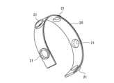
- FIG. 20 A perspective view of the frame 20 is shown in FIG.
- the frame 20 is made of a rigid material such as polyamide resin, and is formed in a strip shape and curved so as to follow the shape of the human head 99 .
- the frame 20 is provided with five electrode unit attachment portions 21 as openings for attaching the electroencephalogram electrode units 10 .
- the position of the electrode unit mounting portion 21 (that is, the mounting position of the electroencephalogram electrode unit 10) corresponds to positions T3, C3, Cz, C4, and T4 in the International 10-20 Electrode Placement Method.
- the inner peripheral surface of the electrode unit mounting portion 21 is threaded, and the electroencephalogram electrode unit 10 is screwed to the body portion 11 by means of the threaded portion 13 (see FIG. 3).
- the screwing amount of the electroencephalogram electrode unit 10 By adjusting the screwing amount of the electroencephalogram electrode unit 10, the amount of protrusion to the head 99 side is adjusted, and the contact amount and contact pressure with the head 99 (scalp) are controlled. Also, by screwing the electroencephalogram electrode unit 10, the hair is parted.
- FIG. 3 shows a front view of the electroencephalogram electrode unit 10.
- the electroencephalogram electrode unit 10 has a substantially cylindrical body 11 and an electroencephalogram detection electrode 50 provided on one end side (lower side in the drawing).
- the trunk portion 11 integrally has a signal extraction portion 12, a threaded portion 13, and an electrode fixing portion 14.
- the threaded portion 13 has a shape in which threads are formed on the cylindrical side surface.
- a signal output portion 12 is provided at one end (upper side in the drawing) of the threaded portion 13 .
- a signal output terminal is provided in the signal extracting portion 12, and is operated by an operator using a predetermined jig as necessary when screwing the electroencephalogram electrode unit 10 to the frame 20.
- a cylindrical electrode fixing portion 14 is provided at the other end (lower side in the drawing) of the threaded portion 13 .
- An electroencephalogram detection electrode 50 is attached to the electrode fixing portion 14 .
- FIG. 4 is a perspective view of the electroencephalogram detection electrode 50.
- FIG. FIG. 5 is a plan view of the electroencephalogram detection electrode 50.
- FIG. FIG. 6 is a cross-sectional view of the electroencephalogram detection electrode 50, and particularly shows a cross-sectional view taken along line X1-X1 in FIG.
- the electroencephalogram detection electrode 50 has a base portion 51 , a projection portion 60 and an electrode portion 80 .
- the base portion 51 and the projection portion 60 are integrally provided by a rubber-like elastic body. A specific material for the elastic body will be described later. Note that the base portion 51 and the projection portion 60 are not limited to being provided integrally, and may be provided separately and assembled with an adhesive or a fitting structure.
- the base portion 51 has a substantially cylindrical shape, and has a circular protrusion forming surface 52 at one end and a circular mounting surface 53 at the other end.
- the attachment surface 53 is attached to the electrode fixing portion 14 of the body portion 11 with an adhesive or the like.
- the fixing structure between the mounting surface 53 and the electrode fixing portion 14 is not particularly limited, and for example, a fitting structure with an uneven shape may be used.
- a plurality of protrusions 60 are arranged in alignment on the protrusion forming surface 52 .
- seven regular hexagonal pyramidal protrusions 60 are arranged in a grid pattern. Specifically, they are provided in an orthorhombic lattice. More specifically, as shown in FIG. 5, six protrusions 60 are arranged in a honeycomb shape so as to surround the central protrusion 60 so that the adjacent protrusions 60 are in contact with each other at their bases without gaps.
- the projection 60 is provided with an electrode portion 80 within a predetermined height range from the apex 61 and is in contact with the head 99 (scalp).
- the shape of the protrusion 60 may be a pyramid such as a triangular pyramid, a square pyramid, a pentagonal pyramid, a hexagonal pyramid, a heptagonal pyramid, an octagonal pyramid, or the like, or a cone.
- An octagonal pyramid or less is preferable, and a square pyramid or a hexagonal pyramid is more preferable.
- pyramids When comparing cones and pyramids as the protrusions 60, pyramids have the advantage of being easier to control the direction of deformation than cones.
- the shape of the protrusion 60 is the square pyramid and the protrusion width and height of the protrusion 60 are the same, and when comparing the shape of the protrusion 60 between the square pyramid and the hexagonal pyramid, the hexagonal pyramid is better than the square pyramid. Not easy to deform. Therefore, the width of the protrusion required to obtain the same strength is smaller for the hexagonal pyramid, and the number of protrusions that can be arranged on the protrusion forming surface 52 of the circular base 51 can be increased.
- the projections 60 are quadrangular pyramids, it is easy to design the arrangement of the plurality of projections 60, and the deformation state when pressed against the head 99 can be easily predicted, enabling stable electroencephalogram measurement. It should be noted that various shapes can be adopted as the grid-like arrangement, and specific examples will be described later with reference to FIG. 10 .
- FIG. 7 and 8 are diagrams for explaining the relationship between the vertex 61 of the protrusion 60 of the electroencephalogram detection electrode and the arrangement of the pores.
- the pores 9 are added to the plan view of the electroencephalogram detection electrode 50 (the electrode portion 80 is omitted).
- FIG. 8 is a diagram for explaining in an easy-to-understand manner the relationship between the distance between the vertices 61, the interval between the pores 9, and the size of the pores 9. As shown in FIG.
- the distance D1 between the most adjacent protrusions 60 (that is, between the vertices 61) satisfies the following formula (1).
- m and n integers of 0 or more, and either m or n is 1 or more
- L distance between pore centers on the subject's scalp
- d pore diameter on the subject's scalp
- the pore center-to-center distance L is, for example, 0. It is 5 mm or more and 1.5 mm or less, preferably 0.6 mm or more and 1.4 mm or less, and more preferably 0.7 mm or more and 1.3 mm or less.
- the distance L between pore centers may be calculated as 1.0 mm.
- the pore diameter d is, for example, 0.05 mm or more and 0.15 mm or less, preferably 0.06 mm or more and 0.14 mm or less, and more preferably 0.07 mm or more and 0.13 mm or less.
- the pore diameter d may be calculated as 0.1 mm.
- a distance D1 between the protrusions 60 is 2 mm or more and 10 mm or less, preferably 2.5 mm or more and 7 mm or less, and more preferably 3 mm or more and 5 mm or less.
- the vertex 61 on the left side of the drawing is located on the right side of the rightmost position of the left pore 9 .
- the right apex 61 is positioned to the left of the leftmost position of the right pore 9 .
- the distance D1 between the vertices 61 is shorter than the distance between the rightmost position of the left pore 9 and the leftmost position of the right pore 9, and satisfies the following formula (1A).
- the vertex 61 on the left side of the drawing is located at the rightmost position of the pore 9 on the left side.
- the right vertex 61 is located at the leftmost position of the right pore 9 .
- the distance D1 between the vertices 61 is equal to the distance between the rightmost position of the left pore 9 and the leftmost position of the right pore 9, and satisfies the following formula (1B).
- D1 L(m 2 +n 2 ) 1/2 -d (1B)
- the vertex 61 on the left side of the drawing is located within the circle indicating the pore 9 on the left side.
- the right vertex 61 is located within the circle representing the right pore 9 .
- each vertex 61 is shown positioned at the center 9a of the pore 9.
- the distance D1 between the vertices 61 is equal to the distance between the centers 9a of the pores 9, and satisfies the following formula (1C).
- D1 L(m 2 +n 2 ) 1/2 (1C)
- the vertex 61 on the left side of the figure is located at the leftmost position of the pore 9 on the left side.
- the right vertex 61 is located at the rightmost position of the right pore 9 .
- the distance D1 between the vertices 61 is equal to the distance between the leftmost position of the left pore 9 and the rightmost position of the right pore 9, and satisfies the following formula (1D).
- D1 L(m 2 +n 2 ) 1/2 +d (1D)
- the vertex 61 on the left side of the drawing is positioned to the left of the leftmost position of the pore 9 on the left side.
- the right vertex 61 is positioned to the right of the rightmost position of the right pore 9 .
- the distance D1 between the vertices 61 is longer than the distance between the leftmost position of the left pore 9 and the rightmost position of the right pore 9, and satisfies the following formula (1E).
- both apexes 61 rest on the pores 9 in the cases of arrangements (2) to (4). That is, when D1 satisfies the following formula (2) for the distance D1 between the vertices 61, both vertices 61 are placed on the pores 9. L(m 2 +n 2 ) 1/2 ⁇ d ⁇ D1 ⁇ L(m 2 +n 2 ) 1/2 +d (2) Therefore, if the distance D1 between the vertices 61 does not satisfy the above formula (2), that is, if the condition satisfies the above formula (1), then Either can avoid getting on the pores 9.
- FIG. 9 is a graph showing the range of the distance D1 that satisfies the above formula (1). Specifically, it shows the range of the distance D1 when the pore center-to-center distance L is 1.0 mm and the pore diameter d is 0.1 mm, and the set of (m, n) is sequentially applied. Here, both m and n are set to 10 or less.
- the horizontal axis indicates the distance D1
- the vertical axis indicates n of (m, n).
- one of the apexes 61 of the two protrusions 60 does not rest on the pores 9 at the distance D1 corresponding to the sanitized area.
- it is the range shown in Table 1 below.
- the distance D1 ⁇ 10 mm is set.
- the protrusion 60 has the shape of a regular quadrangular pyramid.
- Nine protrusions 60 are arranged on the protrusion forming surface 52 in a matrix of 3 ⁇ 3. That is, the protrusions 60 (vertices 61) are arranged in a square lattice.
- the projecting portion 60 has the shape of a regular quadrangular pyramid. Seven protrusions 60 are arranged in an oblique grid pattern on the protrusion forming surface 52 . Specifically, two protrusions 60 are arranged in the first row, three protrusions 60 in the second line, and two protrusions 60 in the third line, so that the adjacent protrusions 60 are placed on the bottom side without gaps. are placed in contact with each other.
- the protrusion 60 has a conical shape.
- Nine protrusions 60 are arranged on the protrusion forming surface 52 in a matrix of 3 ⁇ 3. That is, the protrusions 60 (vertices 61) are arranged in a square lattice.
- the protrusion 60 has a conical shape. Seven protrusions 60 (apexes 61) are arranged in an equilateral triangular lattice on the protrusion forming surface 52 so that the adjacent bases are in contact with each other.
- the protrusion 60 has the shape of an equilateral triangular pyramid. Thirteen protrusions 60 are arranged in a triangular lattice on the protrusion forming surface 52 such that adjacent bases overlap each other. Apices 61 of the protrusions 60 are arranged in a regular hexagonal lattice.
- the distance D1 between the vertices 61 satisfies the above-described formula (1).
- all the apexes 61 that is, all the electrode portions 80 can be reliably prevented from being placed on the pores 9, and stable electroencephalogram measurement can be realized.
- the signal line 69 can adopt various arrangement structures as long as it is a mode that conducts the inside of the protrusion 60 .
- the tip of the signal line 69 may be any of a structure that protrudes, a structure that is substantially on the same plane, and a structure that is buried with respect to the tip of the protrusion 60 or the inclined surface of the tip. From the viewpoint of connection stability with the electrode part 80, a projecting structure may be used. A projecting portion of the tip of the signal line 69 is partially or wholly covered with the electrode portion 80 .
- the projecting structure of the tip of the signal line 69 may be unfolded, folded, or wrapped around the surface of the tip of the projection 60 . Also, the signal line 69 may not coincide with the vertical line extending from the vertex 61 of the protrusion 60 and may be inclined with respect to the vertical line.
- the electroencephalogram detection electrode 50 is a rubber-like elastic body as described above.
- the rubber-like elastic body is rubber or a thermoplastic elastomer (also simply referred to as “elastomer (TPE)”). Examples of rubber include silicone rubber.
- thermoplastic elastomers examples include styrene-based TPE (TPS), olefin-based TPE (TPO), vinyl chloride-based TPE (TPVC), urethane-based TPE (TPU), ester-based TPE (TPEE), and amide-based TPE (TPAE).
- TPS styrene-based TPE
- TPO olefin-based TPE
- TPVC vinyl chloride-based TPE
- TPU urethane-based TPE
- TPEE ester-based TPE
- TPAE amide-based TPE
- the type A durometer hardness of the surface of the electroencephalogram detection electrode 50 (protrusion 60 or base 51) measured in accordance with JIS K 6253 (1997) at 37°C. is rubber hardness A, the rubber hardness A is, for example, 15 or more and 55 or less.
- the silicone rubber-based curable composition will be described.
- the silicone rubber can be composed of a cured product of a silicone rubber-based curable composition.
- the curing step of the silicone rubber-based curable resin composition is, for example, heating at 100 to 250° C. for 1 to 30 minutes (primary curing), followed by post-baking (secondary curing) at 100 to 200° C. for 1 to 4 hours. It is done by
- An insulating silicone rubber is a silicone rubber that does not contain a conductive filler
- a conductive silicone rubber is a silicone rubber that contains a conductive filler
- the silicone rubber-based curable composition according to this embodiment can contain a vinyl group-containing organopolysiloxane (A).
- the vinyl group-containing organopolysiloxane (A) is a polymer that is the main component of the silicone rubber-based curable composition of the present embodiment.
- the insulating silicone rubber-based curable composition and the conductive silicone rubber-based curable composition may contain the same vinyl group-containing linear organopolysiloxane.
- the vinyl group-containing linear organopolysiloxane of the same kind includes at least the same vinyl group with the same functional group and has a linear shape. can be different.
- the insulating silicone rubber-based curable composition and the conductive silicone rubber-based curable composition may further contain different vinyl group-containing organopolysiloxanes.
- the vinyl group-containing organopolysiloxane (A) can contain a vinyl group-containing linear organopolysiloxane (A1) having a linear structure.
- the vinyl group-containing linear organopolysiloxane (A1) has a linear structure and contains vinyl groups, and the vinyl groups serve as cross-linking points during curing.
- the vinyl group content of the vinyl group-containing linear organopolysiloxane (A1) is not particularly limited, but for example, it preferably has two or more vinyl groups in the molecule and is 15 mol % or less. , 0.01 to 12 mol %.
- the amount of vinyl groups in the vinyl group-containing linear organopolysiloxane (A1) is optimized, and a network can be reliably formed with each component described later.
- " ⁇ " means including both numerical values.
- the vinyl group content is the mol % of the vinyl group-containing siloxane units when the total units constituting the vinyl group-containing linear organopolysiloxane (A1) are taken as 100 mol %. .
- one vinyl group is considered to be one vinyl group-containing siloxane unit.
- the degree of polymerization of the vinyl group-containing linear organopolysiloxane (A1) is not particularly limited, it is, for example, preferably in the range of about 1,000 to 10,000, more preferably in the range of about 2,000 to 5,000.
- the degree of polymerization can be determined, for example, as a polystyrene-equivalent number-average polymerization degree (or number-average molecular weight) in GPC (gel permeation chromatography) using chloroform as a developing solvent.
- the specific gravity of the vinyl group-containing linear organopolysiloxane (A1) is not particularly limited, but is preferably in the range of about 0.9 to 1.1.
- the heat resistance, flame retardancy, chemical stability, etc. of the resulting silicone rubber can be improved by using those having the degree of polymerization and specific gravity within the ranges described above. can be improved.
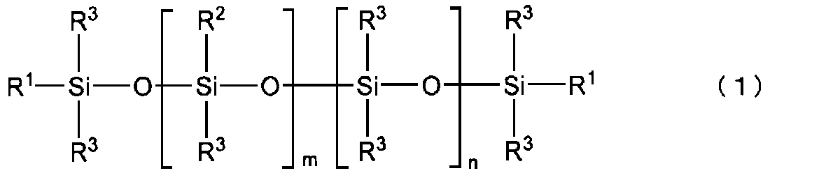
- vinyl group-containing linear organopolysiloxane (A1) those having a structure represented by the following formula (1) are particularly preferable.
- R 1 is a substituted or unsubstituted alkyl group, alkenyl group, aryl group, or a hydrocarbon group of a combination thereof having 1 to 10 carbon atoms.
- the alkyl group having 1 to 10 carbon atoms includes, for example, methyl group, ethyl group, propyl group, etc. Among them, methyl group is preferred.
- the alkenyl group having 1 to 10 carbon atoms includes, for example, vinyl group, allyl group, butenyl group, etc. Among them, vinyl group is preferred.
- the aryl group having 1 to 10 carbon atoms includes, for example, a phenyl group.
- R 2 is a substituted or unsubstituted alkyl group, alkenyl group, aryl group having 1 to 10 carbon atoms, or a hydrocarbon group combining these.
- the alkyl group having 1 to 10 carbon atoms includes, for example, methyl group, ethyl group, propyl group, etc. Among them, methyl group is preferred.
- alkenyl groups having 1 to 10 carbon atoms include vinyl groups, allyl groups and butenyl groups.
- Examples of the aryl group having 1 to 10 carbon atoms include a phenyl group.
- R 3 is a substituted or unsubstituted alkyl group having 1 to 8 carbon atoms, an aryl group, or a hydrocarbon group combining these.
- the alkyl group having 1 to 8 carbon atoms includes, for example, methyl group, ethyl group, propyl group, etc. Among them, methyl group is preferred.
- Examples of the aryl group having 1 to 8 carbon atoms include a phenyl group.
- examples of substituents for R 1 and R 2 in formula (1) include methyl group and vinyl group, and examples of substituents for R 3 include methyl group.
- a plurality of R 1 are independent of each other and may be different or the same. Furthermore, the same applies to R 2 and R 3 .
- m and n are the numbers of repeating units constituting the vinyl group-containing linear organopolysiloxane (A1) represented by formula (1), m is an integer of 0 to 2000, and n is 1000 to 10000. is an integer of m is preferably 0-1000 and n is preferably 2000-5000.
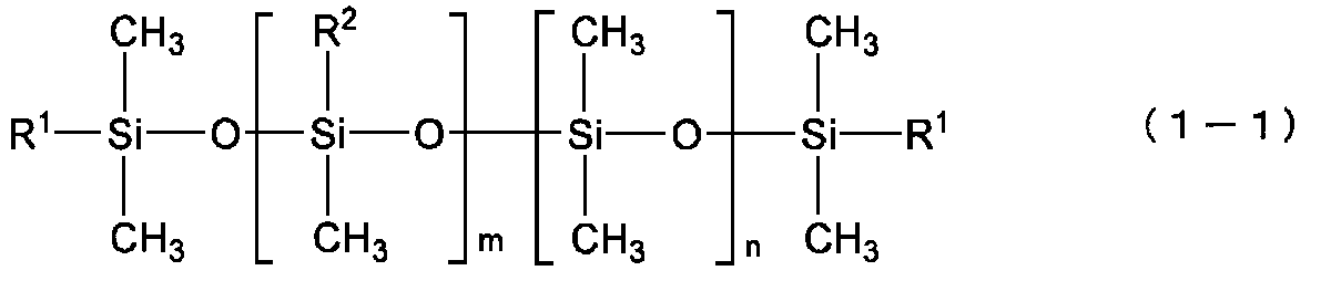
- vinyl group-containing linear organopolysiloxane (A1) represented by formula (1) include, for example, those represented by the following formula (1-1).
- R 1 and R 2 are each independently a methyl group or a vinyl group, and at least one is a vinyl group.
- the vinyl group-containing linear organopolysiloxane (A1) a first vinyl group-containing vinyl group having a vinyl group content of 2 or more vinyl groups in the molecule and not more than 0.4 mol% It contains a linear organopolysiloxane (A1-1) and a second vinyl group-containing linear organopolysiloxane (A1-2) having a vinyl group content of 0.5 to 15 mol%. It is preferable to have As crude rubber, which is a raw material of silicone rubber, a first vinyl group-containing linear organopolysiloxane (A1-1) having a general vinyl group content and a second vinyl group-containing linear organopolysiloxane having a high vinyl group content were used.
- the vinyl groups can be unevenly distributed, and the crosslink density can be more effectively formed in the crosslink network of the silicone rubber. As a result, the tear strength of silicone rubber can be increased more effectively.
- the vinyl group-containing linear organopolysiloxane (A1) for example, a unit in which R 1 is a vinyl group and/or a unit in which R 2 is a vinyl group in the above formula (1-1) , a first vinyl group-containing linear organopolysiloxane (A1-1) having 2 or more in the molecule and containing 0.4 mol% or less, and a unit in which R 1 is a vinyl group and / or R It is preferable to use a second vinyl group-containing linear organopolysiloxane (A1-2) containing 0.5 to 15 mol % of units in which 2 is a vinyl group.
- the first vinyl group-containing linear organopolysiloxane (A1-1) preferably has a vinyl group content of 0.01 to 0.2 mol %.
- the second vinyl group-containing linear organopolysiloxane (A1-2) preferably has a vinyl group content of 0.8 to 12 mol %.
- (A1-1) and (A1-2) are not particularly limited, but for example, the weight ratio of (A1-1):(A1-2) is preferably 50:50 to 95:5, and 80:20 to 90: 10 is more preferred.
- the first and second vinyl group-containing linear organopolysiloxanes (A1-1) and (A1-2) may be used singly or in combination of two or more. good.
- the vinyl group-containing organopolysiloxane (A) may also contain a vinyl group-containing branched organopolysiloxane (A2) having a branched structure.
- the silicone rubber-based curable composition of the present embodiment may contain a cross-linking agent.
- Cross-linking agents can include organohydrogenpolysiloxanes (B).
- Organohydrogenpolysiloxane (B) is classified into linear organohydrogenpolysiloxane (B1) having a linear structure and branched organohydrogenpolysiloxane (B2) having a branched structure. Either or both may be included.
- the insulating silicone rubber-based curable composition and the conductive silicone rubber-based curable composition may contain the same type of cross-linking agent.
- the same type of cross-linking agent should have at least a common structure such as a linear structure or a branched structure, and may contain different molecular weight distributions and different functional groups in the molecule, and the amount added may be different.
- the insulating silicone rubber-based curable composition and the conductive silicone rubber-based curable composition may further contain different cross-linking agents.
- the linear organohydrogenpolysiloxane (B1) has a linear structure and a structure ( ⁇ Si—H) in which hydrogen is directly bonded to Si, and is the vinyl group-containing organopolysiloxane (A). It is a polymer that undergoes a hydrosilylation reaction with other vinyl groups and other vinyl groups contained in other components of the silicone rubber-based curable composition to crosslink these components.
- the molecular weight of the linear organohydrogenpolysiloxane (B1) is not particularly limited, for example, the weight average molecular weight is preferably 20,000 or less, more preferably 1,000 or more and 10,000 or less.
- the weight average molecular weight of the linear organohydrogenpolysiloxane (B1) can be measured, for example, by polystyrene conversion in GPC (gel permeation chromatography) using chloroform as a developing solvent.
- the linear organohydrogenpolysiloxane (B1) does not have a vinyl group. Thereby, it is possible to accurately prevent the progress of the cross-linking reaction in the molecule of the linear organohydrogenpolysiloxane (B1).
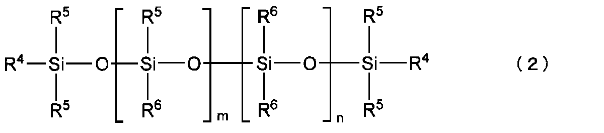
- linear organohydrogenpolysiloxane (B1) for example, one having a structure represented by the following formula (2) is preferably used.
- R 4 is a substituted or unsubstituted alkyl group, alkenyl group, aryl group having 1 to 10 carbon atoms, a hydrocarbon group combining these groups, or a hydride group.
- the alkyl group having 1 to 10 carbon atoms includes, for example, methyl group, ethyl group, propyl group, etc. Among them, methyl group is preferred.
- alkenyl groups having 1 to 10 carbon atoms include vinyl groups, allyl groups and butenyl groups.
- the aryl group having 1 to 10 carbon atoms include a phenyl group.
- R 5 is a substituted or unsubstituted alkyl group, alkenyl group, aryl group having 1 to 10 carbon atoms, a hydrocarbon group combining these, or a hydride group.
- alkyl group having 1 to 10 carbon atoms include methyl group, ethyl group and propyl group, with methyl group being preferred.
- alkenyl groups having 1 to 10 carbon atoms include vinyl groups, allyl groups and butenyl groups.
- Examples of the aryl group having 1 to 10 carbon atoms include a phenyl group.
- a plurality of R 4 are independent of each other and may be different from each other or may be the same. The same is true for R5 . However, at least two or more of the plurality of R 4 and R 5 are hydride groups.
- R 6 is a substituted or unsubstituted alkyl group having 1 to 8 carbon atoms, an aryl group, or a hydrocarbon group combining these.
- the alkyl group having 1 to 8 carbon atoms includes, for example, methyl group, ethyl group, propyl group, etc. Among them, methyl group is preferred.
- Examples of the aryl group having 1 to 8 carbon atoms include a phenyl group.
- a plurality of R 6 are independent from each other and may be different from each other or may be the same.
- substituents for R 4 , R 5 and R 6 in formula (2) include methyl group and vinyl group, and methyl group is preferred from the viewpoint of preventing intramolecular cross-linking reaction.
- m and n are the numbers of repeating units constituting the linear organohydrogenpolysiloxane (B1) represented by formula (2), m is an integer of 2 to 150, and n is an integer of 2 to 150. is.
- m is an integer from 2-100 and n is an integer from 2-100.
- the straight-chain organohydrogenpolysiloxane (B1) may be used alone or in combination of two or more.
- the branched organohydrogenpolysiloxane (B2) has a branched structure, it is a component that forms regions with a high crosslink density and greatly contributes to the formation of a loose and dense structure of crosslink density in the silicone rubber system. Further, like the linear organohydrogenpolysiloxane (B1), it has a structure ( ⁇ Si—H) in which hydrogen is directly bonded to Si, and in addition to the vinyl group of the vinyl group-containing organopolysiloxane (A), silicone It is a polymer that undergoes a hydrosilylation reaction with the vinyl groups of the components blended in the rubber-based curable composition to crosslink these components.
- the specific gravity of the branched organohydrogenpolysiloxane (B2) is in the range of 0.9 to 0.95.
- the branched organohydrogenpolysiloxane (B2) does not have a vinyl group. Thereby, it is possible to accurately prevent the progress of the cross-linking reaction in the molecule of the branched organohydrogenpolysiloxane (B2).
- branched organohydrogenpolysiloxane (B2) one represented by the following average compositional formula (c) is preferable.
- R 7 is a monovalent organic group, a is an integer ranging from 1 to 3, m is the number of H a (R 7 ) 3-a SiO 1/2 units, n is SiO 4/ is a number of 2 units)
- R 7 is a monovalent organic group, preferably a substituted or unsubstituted alkyl group having 1 to 10 carbon atoms, an aryl group, or a hydrocarbon group combining these.
- the alkyl group having 1 to 10 carbon atoms includes, for example, methyl group, ethyl group, propyl group, etc. Among them, methyl group is preferable.
- Examples of the aryl group having 1 to 10 carbon atoms include a phenyl group.
- a is the number of hydride groups (hydrogen atoms directly bonded to Si) and is an integer in the range of 1 to 3, preferably 1.
- m is the number of H a (R 7 ) 3-a SiO 1/2 units
- n is the number of SiO 4/2 units.
- the branched organohydrogenpolysiloxane (B2) has a branched structure.
- the linear organohydrogenpolysiloxane (B1) and the branched organohydrogenpolysiloxane (B2) differ in that their structures are linear or branched.
- the number of bound alkyl groups R (R/Si) is 1.8 to 2.1 for the linear organohydrogenpolysiloxane (B1) and 0.8 to 1 for the branched organohydrogenpolysiloxane (B2). .7 range.
- the branched organohydrogenpolysiloxane (B2) has a branched structure, for example, when heated to 1000° C. at a heating rate of 10° C./min in a nitrogen atmosphere, the residual amount is 5% or more. becomes.
- the straight-chain organohydrogenpolysiloxane (B1) is straight-chain, the amount of residue after heating under the above conditions is almost zero.
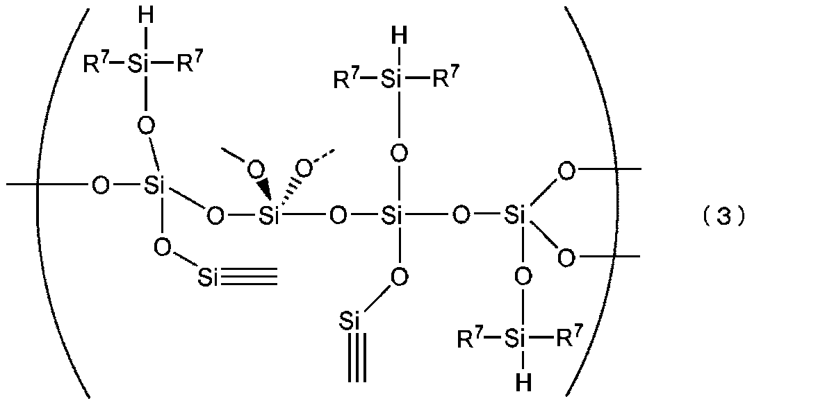
- branched organohydrogenpolysiloxane (B2) include those having a structure represented by the following formula (3).
- R 7 is a substituted or unsubstituted alkyl group having 1 to 8 carbon atoms, an aryl group, a hydrocarbon group combining these, or a hydrogen atom.
- the alkyl group having 1 to 8 carbon atoms includes, for example, methyl group, ethyl group, propyl group, etc. Among them, methyl group is preferable.
- Examples of the aryl group having 1 to 8 carbon atoms include a phenyl group.
- the substituent of R7 include a methyl group and the like.
- a plurality of R 7 are independent of each other and may be different from each other or may be the same.
- the branched organohydrogenpolysiloxane (B2) may be used alone or in combination of two or more.
- the amount of hydrogen atoms (hydride groups) directly bonded to Si is not particularly limited.
- linear organohydrogenpolysiloxane (B1) and branched organohydrogenpolysiloxane are The total amount of hydride groups in the siloxane (B2) is preferably from 0.5 to 5 mol, more preferably from 1 to 3.5 mol.
- the silicone rubber-based curable composition according to this embodiment contains a non-conductive filler.
- the non-conductive filler may contain silica particles (C) as needed. Thereby, the hardness and mechanical strength of the elastomer can be improved.
- the insulating silicone rubber-based curable composition and the conductive silicone rubber-based curable composition may contain the same type of non-conductive filler.
- Non-conductive fillers of the same type may have at least common constituent materials, and may differ in particle size, specific surface area, surface treatment agent, or addition amount thereof.
- the insulating silicone rubber-based curable composition and the conductive silicone rubber-based curable composition may further contain different silane coupling agents.
- the silica particles (C) are not particularly limited, but for example, fumed silica, calcined silica, precipitated silica, etc. are used. These may be used alone or in combination of two or more.
- the silica particles (C) preferably have a BET specific surface area of, for example, 50 to 400 m 2 /g, more preferably 100 to 400 m 2 /g. Also, the average primary particle size of the silica particles (C) is, for example, preferably 1 to 100 nm, more preferably about 5 to 20 nm.
- silica particles (C) having a specific surface area and an average particle size within the above ranges, the hardness and mechanical strength of the formed silicone rubber can be improved, especially the tensile strength can be improved.
- the silicone rubber-based curable composition of the present embodiment can contain a silane coupling agent (D).
- Silane coupling agent (D) can have a hydrolyzable group. The hydrolyzable group is hydrolyzed with water to form a hydroxyl group, and the hydroxyl group undergoes a dehydration condensation reaction with the hydroxyl group on the surface of the silica particle (C), thereby modifying the surface of the silica particle (C).
- the insulating silicone rubber-based curable composition and the conductive silicone rubber-based curable composition may contain the same type of silane coupling agent.
- the silane coupling agents of the same kind should have at least a common functional group, and may differ in other functional groups in the molecule and in the amount added.
- the insulating silicone rubber-based curable composition and the conductive silicone rubber-based curable composition may further contain different silane coupling agents.
- this silane coupling agent (D) can contain a silane coupling agent having a hydrophobic group.
- the hydrophobic group is imparted to the surface of the silica particles (C), so that the cohesive force of the silica particles (C) in the silicone rubber-based curable composition and further in the silicone rubber is reduced (hydrogen aggregation due to bonding is reduced), and as a result, it is presumed that the dispersibility of the silica particles (C) in the silicone rubber-based curable composition is improved. This increases the interface between the silica particles (C) and the rubber matrix, increasing the reinforcing effect of the silica particles (C).
- the slipperiness of the silica particles (C) within the matrix is improved when the rubber matrix is deformed.
- the improved dispersibility and slipperiness of the silica particles (C) improve the mechanical strength (for example, tensile strength and tear strength) of the silicone rubber due to the silica particles (C).
- the silane coupling agent (D) can contain a silane coupling agent having a vinyl group.
- vinyl groups are introduced onto the surfaces of the silica particles (C). Therefore, during curing of the silicone rubber-based curable composition, that is, a hydrosilylation reaction occurs between the vinyl group of the vinyl group-containing organopolysiloxane (A) and the hydride group of the organohydrogenpolysiloxane (B). , When a network (crosslinked structure) is formed by these, the vinyl groups possessed by the silica particles (C) also participate in the hydrosilylation reaction with the hydride groups possessed by the organohydrogenpolysiloxane (B). Silica particles (C) also come to be taken in. As a result, it is possible to reduce the hardness and increase the modulus of the formed silicone rubber.
- silane coupling agent (D) a silane coupling agent having a hydrophobic group and a silane coupling agent having a vinyl group can be used in combination.
- silane coupling agent (D) examples include those represented by the following formula (4).
- n represents an integer of 1-3.
- Y represents a functional group having a hydrophobic group, a hydrophilic group or a vinyl group; when n is 1, it is a hydrophobic group; when n is 2 or 3, at least one of It is a hydrophobic group.
- X represents a hydrolyzable group.
- the hydrophobic group is an alkyl group having 1 to 6 carbon atoms, an aryl group, or a hydrocarbon group having a combination thereof, and examples thereof include a methyl group, an ethyl group, a propyl group, a phenyl group, and the like. Methyl groups are preferred.
- the hydrophilic group includes, for example, a hydroxyl group, a sulfonic acid group, a carboxyl group, a carbonyl group, etc. Among them, a hydroxyl group is particularly preferable.
- the hydrophilic group may be contained as a functional group, but is preferably not contained from the viewpoint of imparting hydrophobicity to the silane coupling agent (D).
- the hydrolyzable group includes an alkoxy group such as a methoxy group and an ethoxy group, a chloro group, a silazane group, and the like.
- a silazane group is preferable because of its high reactivity with the silica particles (C).
- a compound having a silazane group as a hydrolyzable group has two structures of (Y n —Si—) in the above formula (4) due to its structural characteristics.
- silane coupling agent (D) represented by the above formula (4) are as follows.
- Those having a hydrophobic group as the functional group include, for example, methyltrimethoxysilane, dimethyldimethoxysilane, phenyltrimethoxysilane, methyltriethoxysilane, dimethyldiethoxysilane, phenyltriethoxysilane, n-propyltrimethoxysilane, alkoxysilanes such as n-propyltriethoxysilane, hexyltrimethoxysilane, hexyltriethoxysilane, decyltrimethoxysilane; chlorosilanes such as methyltrichlorosilane, dimethyldichlorosilane, trimethylchlorosilane, phenyltrichlorosilane; hexamethyldisilazane.
- silane coupling agent having a trimethylsilyl group containing one or more selected from the group consisting of hexamethyldisilazane, trimethylchlorosilane, trimethylmethoxysilane, and trimethylethoxysilane is preferred.
- Examples of those having a vinyl group as the functional group include methacryloxypropyltriethoxysilane, methacryloxypropyltrimethoxysilane, methacryloxypropylmethyldiethoxysilane, methacryloxypropylmethyldimethoxysilane, vinyltriethoxysilane, and vinyltrimethoxysilane.
- alkoxysilanes such as silane and vinylmethyldimethoxysilane
- chlorosilanes such as vinyltrichlorosilane and vinylmethyldichlorosilane
- divinyltetramethyldisilazane divinyltetramethyldisilazane.
- a silane coupling agent having a vinyl group-containing organosilyl group containing one or more selected from the group consisting of methyldimethoxysilane is preferred.
- silane coupling agent (D) contains two kinds of a silane coupling agent having a trimethylsilyl group and a silane coupling agent having a vinyl group-containing organosilyl group
- those having a hydrophobic group include hexamethyldisilazane, Divinyltetramethyldisilazane is preferably included as one having a vinyl group.
- the ratio of (D1) and (D2) is not particularly limited, but for example, (D1):(D2) in a weight ratio of 1:0.001 to 1:0.35, preferably 1:0.01 to 1:0.20, more preferably 1:0.03 to 1:0 .15. Desired physical properties of the silicone rubber can be obtained by setting it to such a numerical range. Specifically, the dispersibility of silica in the rubber and the crosslinkability of the rubber can be balanced.
- the lower limit of the content of the silane coupling agent (D) is preferably 1% by mass or more with respect to 100 parts by weight of the total amount of the vinyl group-containing organopolysiloxane (A). It is more preferably at least 5% by mass, even more preferably at least 5% by mass.
- the upper limit of the content of the silane coupling agent (D) is preferably 100% by mass or less, and 80% by mass or less, with respect to 100 parts by weight of the total amount of the vinyl group-containing organopolysiloxane (A). It is more preferable that the content is 40% by mass or less.
- the silicone rubber can have appropriate mechanical properties.
- the silicone rubber-based curable composition according to this embodiment may contain a catalyst.
- the catalyst may contain platinum or a platinum compound (E).
- Platinum or a platinum compound (E) is a catalytic component that acts as a catalyst during curing.
- the amount of platinum or platinum compound (E) added is a catalytic amount.
- the insulating silicone rubber-based curable composition and the conductive silicone rubber-based curable composition may contain the same type of catalyst. Catalysts of the same kind may have at least common constituent materials, and the catalysts may contain different compositions and may differ in addition amount.
- the insulating silicone rubber-based curable composition and the conductive silicone rubber-based curable composition may further contain different catalysts.
- platinum or platinum compound (E) a known one can be used, for example, platinum black, platinum supported on silica or carbon black, chloroplatinic acid or an alcohol solution of chloroplatinic acid, A complex salt of platinic acid and olefin, a complex salt of chloroplatinic acid and vinyl siloxane, and the like are included.
- the platinum or platinum compound (E) may be used alone or in combination of two or more.
- the content of platinum or platinum compound (E) in the silicone rubber-based curable composition means the amount of catalyst, and can be set as appropriate.
- (A), silica particles (C), the total amount of 100 parts by weight of the silane coupling agent (D), platinum group metal is an amount of 0.01 to 1000 ppm by weight unit, preferably 0. The amount is 1 to 500 ppm.
- the silicone rubber-based curable composition according to the present embodiment may contain water (F) in addition to the above components (A) to (E).
- Water (F) is a component that functions as a dispersion medium for dispersing each component contained in the silicone rubber-based curable composition and contributes to the reaction between the silica particles (C) and the silane coupling agent (D). . Therefore, the silica particles (C) and the silane coupling agent (D) can be linked to each other more reliably in the silicone rubber, and uniform properties can be exhibited as a whole.
- the silicone rubber-based curable composition of the present embodiment may further contain other components in addition to the above components (A) to (F).
- Other components include silica particles (C) such as diatomaceous earth, iron oxide, zinc oxide, titanium oxide, barium oxide, magnesium oxide, cerium oxide, calcium carbonate, magnesium carbonate, zinc carbonate, glass wool, and mica.
- additives such as inorganic fillers, reaction inhibitors, dispersants, pigments, dyes, antistatic agents, antioxidants, flame retardants, and thermal conductivity improvers.
- the conductive solution (conductive silicone rubber composition) according to the present embodiment contains the conductive filler and solvent in addition to the silicone rubber-based curable composition containing no conductive filler.
- solvents can be used as the solvent, and for example, a high boiling point solvent can be included. These may be used alone or in combination of two or more.
- solvents examples include aliphatic hydrocarbons such as pentane, hexane, cyclohexane, heptane, methylcyclohexane, ethylcyclohexane, octane, decane, dodecane, and tetradecane; benzene, toluene, ethylbenzene, xylene, trifluoromethylbenzene; , aromatic hydrocarbons such as benzotrifluoride; diethyl ether, diisopropyl ether, dibutyl ether, cyclopentyl methyl ether, cyclopentyl ethyl ether, ethylene glycol dimethyl ether, ethylene glycol diethyl ether, diethylene glycol dimethyl ether, 1,4-dioxane, 1,3 - ethers such as dioxane and tetrahydrofuran; haloalkanes such as
- the conductive solution can have a viscosity suitable for various coating methods such as spray coating and dip coating.
- the lower limit of the content of the silica particles (C) contained in the electrode part 80 is the amount of the silica particles (C) and the conductive filler.
- it is 1% by mass or more, preferably 3% by mass or more, and more preferably 5% by mass or more, relative to the total amount of 100% by mass.
- the upper limit of the content of the silica particles (C) contained in the electrode part 80 is, for example, 20% by mass or less with respect to the total amount of 100% by mass of the silica particles (C) and the conductive filler, It is preferably 15% by mass or less, more preferably 10% by mass or less. Thereby, the conductivity, mechanical strength, and flexibility of the electrode portion 80 can be balanced.
- a conductive silicone rubber can be obtained by heating and drying the conductive solution as necessary.
- the conductive silicone rubber may be configured without silicone oil. As a result, it is possible to suppress deterioration in conductivity due to bleeding out of the silicone oil onto the surface of the electrode portion 80 .
- a known signal line 69 can be used, and for example, it can be made of a conductive fiber.
- the conductive fiber one or more selected from the group consisting of metal fiber, metal-coated fiber, carbon fiber, conductive polymer fiber, conductive polymer-coated fiber, and conductive paste-coated fiber can be used. These may be used alone or in combination of two or more.
- the metal material of the metal fibers and metal-coated fibers is not limited as long as it has conductivity, but copper, silver, gold, nickel, tin, lead, zinc, bismuth, antimony, stainless steel, aluminum, silver/chloride silver and alloys thereof; These may be used alone or in combination of two or more. Among these, silver can be used from the viewpoint of conductivity. Moreover, it is preferable that the metal material does not contain a metal such as chromium that causes a load on the environment.
- the fiber materials of the metal-coated fibers, conductive polymer-coated fibers, and conductive paste-coated fibers are not particularly limited, but may be synthetic fibers, semi-synthetic fibers, or natural fibers. Among these, it is preferable to use polyester, nylon, polyurethane, silk, cotton, and the like. These may be used alone or in combination of two or more.
- Examples of the carbon fibers include PAN-based carbon fibers and pitch-based carbon fibers.
- the conductive polymer material of the conductive polymer fiber and the conductive polymer-coated fiber is, for example, a mixture of a conductive polymer such as polythiophene, polypyrrole, polyaniline, polyacetylene, polyphenylene vinylene, polynaphthalene, and derivatives thereof and a binder resin, Alternatively, an aqueous solution of a conductive polymer such as PEDOT-PSS ((3,4-ethylenedioxythiophene)-poly(styrenesulfonic acid)) is used.
- PEDOT-PSS ((3,4-ethylenedioxythiophene)-poly(styrenesulfonic acid)
- the resin material contained in the conductive paste of the conductive paste-coated fiber is not particularly limited, but preferably has elasticity. It can contain one or more selected from the group consisting of propylene rubbers. These may be used alone or in combination of two or more.
- the conductive filler contained in the conductive paste of the conductive paste-coated fiber is not particularly limited, and known conductive materials may be used, such as metal particles, metal fibers, metal-coated fibers, carbon black, acetylene black, graphite, carbon It may contain one or more selected from the group consisting of fibers, carbon nanotubes, conductive polymers, conductive polymer-coated fibers and metal nanowires.
- the metal constituting the conductive filler is not particularly limited, but for example, copper, silver, gold, nickel, tin, lead, zinc, bismuth, antimony, silver/silver chloride, or at least one of these alloys. or, alternatively, two or more of these.
- silver or copper is preferable because of its high conductivity and high availability.
- the signal line 69 may be composed of twisted yarn obtained by twisting a plurality of linear conductive fibers. Thereby, disconnection of the signal line 69 at the time of deformation can be suppressed.
- the coating of the conductive fiber means not only covering the outer surface of the fiber material, but also, in the case of a twisted yarn obtained by twisting single fibers, a metal or a conductive polymer is added between the fibers in the twisted yarn. , or impregnated with a conductive paste to cover each single fiber constituting the twisted yarn.
- the tensile elongation at break of the signal wire 69 is, for example, 1% to 50%, preferably 1.5% to 45%. By setting the value within such a numerical range, it is possible to suppress excessive deformation of the protrusion 60 while suppressing breakage during deformation.
- the conductive member of the electrode part 80 is, for example, a paste containing a highly conductive metal.
- the highly conductive metal includes one or more selected from the group consisting of copper, silver, gold, nickel, tin, lead, zinc, bismuth, antimony, or alloys thereof.
- silver, silver chloride, and copper are suitable from the viewpoint of availability and conductivity.
- the electrode portion 80 is formed of a paste containing a highly conductive metal
- the apex 61 of the protrusion 60 made of a rubber-like elastic body is dipped (immersion-coated) in a paste-like conductive solution containing a highly conductive metal. )do.
- the electrode portion 80 is formed on the surface of the projection portion 60 .
- the electrode section 80 as a conductive resin layer may be formed by applying a conductive solution containing a conductive filler and a solvent to the surface of the protrusion 60 . At this time, by using the same type of material (silicone rubber) as the solvent for the protrusions 60, the adhesion of the electrode portions 80 (conductive resin layer) can be enhanced.
- a conductive silicone rubber can be obtained by heating and drying the conductive solution as necessary.
- the conductive silicone rubber may be configured without silicone oil. As a result, it is possible to suppress deterioration in conductivity due to bleeding out of the silicone oil onto the surface of the electrode portion 80 .
- An example of a method for manufacturing the electroencephalogram detection electrode 50 of this embodiment can include the following steps. First, using a mold, the silicone rubber-based curable composition is molded under heat and pressure to obtain a molded body comprising the base portion 51 and the projection portion 60 . Subsequently, a signal line 69 is threaded through each protrusion 60 of the obtained molding using a sewing needle. A pasty conductive solution is dip-coated on the protruding portion 60 (predetermined range including the vertex 61) of the molded body obtained thereafter, and post-curing is performed after heating and drying. Thereby, the electrode portion 80 can be formed on the surface of the projection portion 60 . As described above, the electroencephalogram detection electrode 50 can be manufactured. During the molding process, insert molding may be used in which the silicone rubber-based curable composition is introduced into the molding space in which the signal line 69 is arranged, and pressurized and heat-molded.
- electroencephalogram measuring device 10 electroencephalogram electrode unit 11 body portion 12 signal extraction portion 13 threaded portion 14 electrode fixing portion 20 frame 21 electrode unit attachment portion 50, 50A to 50E electroencephalogram detection electrode 51 base portion 52 protrusion forming surface 60 protrusion portion 61 Vertex 69 Signal line 80 Electrode part
Landscapes
- Life Sciences & Earth Sciences (AREA)
- Health & Medical Sciences (AREA)
- Medical Informatics (AREA)
- Biophysics (AREA)
- Pathology (AREA)
- Engineering & Computer Science (AREA)
- Biomedical Technology (AREA)
- Heart & Thoracic Surgery (AREA)
- Physics & Mathematics (AREA)
- Molecular Biology (AREA)
- Surgery (AREA)
- Animal Behavior & Ethology (AREA)
- General Health & Medical Sciences (AREA)
- Public Health (AREA)
- Veterinary Medicine (AREA)
- Measurement And Recording Of Electrical Phenomena And Electrical Characteristics Of The Living Body (AREA)
Abstract
Description
特許文献1では、基底部と、前記基底部から突出して設けられた、ゴムからなる突出部と、前記突出部の先端に設けられ、前記脳波測定用電極の外部と電気的に接続され、前記脳波の測定時に頭皮に接触する、金属からなる接触部と、を備える脳波測定用電極(脳波検出用電極)が開示されている。
特許文献2では、被験者の身体に接触する電極部材と、前記電極部材を支持する導電性の支持部材とを有し、少なくとも前記電極部材は導電性ゴムからなり、前記導電性ゴムは、シリコーンゴムと銀粉とを含んでなり、前記支持部材から複数の前記電極部材がブラシ状に突出するように設けられ、脳波測定に用いられることを特徴とする生体電極が開示されている。
特許文献3では、弾性体からなる母材と、前記母材の表面に形成された構造体とを備える脳波測定用電極であって、前記母材は、頭皮に接触する接触面を有する突出部を備え、前記構造体は、複数のナノ炭素材料を含み、前記複数のナノ炭素材料が、互いに接続されたネットワーク構造を形成していると共に、前記母材の表面に固定されていることを特徴とする脳波測定用電極が開示されている。
特許文献1~3の技術では、上記課題を考慮しておらず、新たな技術が求められていた。
[1]
被験者の頭皮に接触して脳波を検出する脳波検出用電極であって、
基部と、
前記基部から突出する複数の錐体形状の突起部と、
前記突起部に設けられた電極部と、
を有し、
前記複数の突起部において、最も隣接する突起部間の距離D1は、下記の式(1)を満たす脳波検出用電極。
D1<L(m2+n2)1/2-d 又は D1>L(m2+n2)1/2+d ・・・(1)
m,n:0以上の整数であって、かつm又はnのいずれかは1以上
L:被験者の頭皮の毛穴中心間距離
d:被験者の頭皮の毛穴径
[2]
前記複数の突起部は、それらの頂点が正方格子を構成するように配置されている、[1]に記載の脳波検出用電極。
[3]
前記複数の突起部は、それらの頂点が正三角格子を構成するように配置されている、[1]に記載の脳波検出用電極。
[4]
前記突起部は錐体である、[1]から[3]までのいずれか1に記載の脳波検出用電極。
[5]
前記突起部が呈する錐体は六角錐である、[4]に記載の脳波検出用電極。
[6]
隣接する前記突起部の底面の辺が接触して配置されている、[5]に記載の脳波検出用電極。
[7]
前記突起部が呈する錐体は円錐である、[6]に記載の脳波検出用電極。
[8]
前記最も隣接する突起部間の距離D1は、2mm以上10mm以下である、[1]から[7]までのいずれか1に記載の脳波検出用電極。
[9]
[1]から[8]までのいずれか1に記載の脳波検出用電極と、
被験者の頭部に装着されるとともに、前記脳波検出用電極を取り付けるフレームと、
を有する脳波測定装置。
[10]
[9]に記載の脳波測定装置を被験者の頭部に装着して脳波測定を行う脳波測定方法。
以下、本発明の実施の形態について、図面を用いて説明する。
図1は人の頭部99に装着した状態の脳波測定装置1を模式的に示す図である。脳波測定装置1を被験者の頭部99に装着して脳波測定を行う脳波測定方法が実行される。脳波測定装置1は、頭部99に装着され、脳波を生体からの電位変動として検出し、検出した脳波を脳波表示装置(図示せず)に出力する。脳波表示装置は、脳波測定装置1が検出した脳波を取得して、モニタ表示したり、データ保存したり、周知の脳波解析処理を行う。
図1に示すように、脳波測定装置1は、複数の脳波電極ユニット10と、フレーム20と、を有する。本実施形態では、脳波電極ユニット10は、5ch分(5個)設けられている。
図2にフレーム20の斜視図を示す。フレーム20は、例えばポリアミド樹脂のような硬質部材で帯状に、かつ人間の頭部99の形状に沿うように湾曲して形成されている。
図3に脳波電極ユニット10の正面図を示す。脳波電極ユニット10は、略円柱状の胴部11と、その一端側(図中下側)に設けられた脳波検出用電極50とを有する。
螺刻部13は、円柱形状の側面に螺刻した形状である。螺刻部13の一端(図中上側)に信号取出部12が設けられている。信号取出部12には信号出力端子が設けられるとともに、脳波電極ユニット10をフレーム20に螺着する際に作業者によって必要に応じて所定の治具を用いて操作される。螺刻部13の他端(図中下側)には、円柱状の電極固定部14が設けられている。電極固定部14に脳波検出用電極50が取り付けられる。
図4は脳波検出用電極50の斜視図である。図5は脳波検出用電極50の平面図である。図6は脳波検出用電極50の断面図であり、特に図5のX1-X1断面図を示す。
突起部形成面52には、複数の突起部60が整列配置されて設けられている。ここでは、7つの正六角錐の突起部60が格子状に配置されている。具体的には、斜方格子状に設けられている。より具体的には、図5に示すように、中央の突起部60を囲むようにして、6つの突起部60が隣接する突起部60同士が隙間無く底辺を接するように、ハニカム状に配置されている。突起部60には、頂点61から所定高さの範囲に電極部80が設けられ頭部99(頭皮)と接触する。突起部60の形状は、三角錐、四角錐、五角錐、六角錐、七角錐、八角錐等の多角錐等の錐体であっても、円錐であってもよく、多角錐の場合は、八角錐以下が好ましく、四角錐または六角錐がより好ましい。
突起部60として円錐と角錐とを比較した場合、円錐に対して角錐では変形方向を制御しやすいという利点がある。
突起部60の形状としては四角錐と突起部60の突起幅と突起高さが同じ場合、突起部60の形状としては四角錐と六角錐を比較した場合、四角錐に比べて六角錘のほうが変形しにくい。よって、同一の強度を得るために必要な突起幅は六角錘のほうが小さくなり、円状である基部51の突起部形成面52に配置できる突起数を多くすることができる。
突起部60が四角錐の場合、複数の突起部60の配置設計が容易であり、また、頭部99に押しつけた際の変形状態を予測しやすく、安定した脳波測定ができる。なお、格子状配置として各種形状を採用でき、具体例については図10で後述する。
図7~9を参照して突起部60の配置を、特に頂点61間の距離と毛穴9の関係に着目して説明する。図7および図8は脳波検出用電極の突起部60の頂点61と毛穴の配置との関係を説明する図である。図7では脳波検出用電極50の平面図(電極部80を省略している)に毛穴9を追加して示している。図8は、頂点61間の距離と、毛穴9の間隔、毛穴9の大きさとの関係を分かりやすく説明する図である。
D1<L(m2+n2)1/2-d 又はD1>L(m2+n2)1/2+d ・・・(1)
m,n:0以上の整数であって、かつm又はnのいずれかは1以上
L:被験者の頭皮の毛穴中心間距離
d:被験者の頭皮の毛穴径
毛穴中心間距離Lは、例えば0.5mm以上1.5mm以下であり、好ましくは0.6mm以上1.4mm以下であり、より好ましくは0.7mm以上1.3mm以下とすることができる。一般的な傾向を考慮すると毛穴中心間距離Lは1.0mmとして計算してもよい。
毛穴径dは、例えば0.05mm以上0.15mm以下であり、好ましくは0.06mm以上0.14mm以下であり、より好ましくは0.07mm以上0.13mm以下とすることができる。一般的な傾向を考慮すると毛穴径dは0.1mmとして計算してもよい。
突起部60(すなわち頂点61)間の距離D1は、2mm以上10mm以下であり、好ましくは2.5mm以上7mm以下であり、より好ましくは3mm以上5mm以下である。距離D1をこのようは範囲とすることで、突起部60の密度を十分に大きくすることができるとともに、突起部60の大きさや強度を適切にすることができる。
D1<L(m2+n2)1/2-d・・・(1A)
頂点61間の距離D1が上記の式(1A)を満たす場合、一方の突起部60の頂点61が毛穴9のどの部分(図の毛穴9を示す円内)に載った場合であっても、他方の突起部60の頂点61は毛穴9に載ることはない。
D1=L(m2+n2)1/2-d・・・(1B)
頂点61間の距離D1が上記の式(1B)を満たす場合、ちょうど配置(2)の状態のときに、両方の突起部60の頂点61が毛穴9に載る。
このとき頂点61間の距離D1は、毛穴9の中心9a間の距離と等しく、下記の式(1C)を満たす。
D1=L(m2+n2)1/2・・・(1C)
D1=L(m2+n2)1/2+d・・・(1D)
頂点61間の距離D1が上記の式(1D)を満たす場合、ちょうど配置(4)の状態のときに、両方の突起部60の頂点61が毛穴9に載る。
D1>L(m2+n2)1/2+d・・・(1E)
頂点61間の距離D1が上記の式(1E)を満たす場合、一方の突起部60の頂点61が毛穴9のどの部分(図の毛穴9を示す円内)に載った場合であっても、他方の突起部60の頂点61は毛穴9に載ることはない。
L(m2+n2)1/2-d≦D1≦L(m2+n2)1/2+d ・・・(2)
したがって、頂点61間の距離D1が上記式(2)を満たさないような条件であれば、すなわち上述の式(1)を満たす条件の場合に、隣接する二つの突起部60の頂点61のうちいずれかは、毛穴9に載ることを回避できる。
グラフでは、横軸が距離D1、縦軸が(m、n)のうちのnを示している。例えば、縦軸でn=1のときに、m=1、2、3、・・・10を適用していったときの、式(1)から得られる範囲を横線(太線)として示している。n=1~10の横線の全てについて、すなわち全ての(m、n)の組について、式(1)を満たす範囲が、グラフ中墨塗で示す領域である。言い換えると、墨塗の領域に対応する距離D1のときに、二つの突起部60の頂点61のうちいずれかは、毛穴9に載ることがない。
具体的には、以下の表1で示す範囲である。ただし、距離D1≦10mmとしている。

図6の脳波検出用電極50の断面形状に示すように、突起部60の内部には、電極部80に接続する導電性の信号線69が設けられている。信号線69は、突起部60の内部を導通する態様であれば各種の配置構造を採用し得る。例えば、信号線69の先端は、突起部60の先端あるいは先端部の傾斜面に対して、突出した構造、略同一面上となる構造、埋没した構造のいずれでもよい。電極部80との接続安定性の観点から、突出した構造を用いてもよい。信号線69の先端の突出部分は、一部または全体が電極部80で覆われている。
脳波検出用電極50(基部51、突起部60)の材料について説明する。脳波検出用電極50は、上述のようにゴム状の弾性体である。ゴム状の弾性体として、具体的にはゴムや熱可塑性エラストマー(単に「エラストマー(TPE)」ともいう)である。ゴムとしては、例えばシリコーンゴムがある。熱可塑性エラストマーとして、例えば、スチレン系TPE(TPS)、オレフィン系TPE(TPO)、塩化ビニル系TPE(TPVC)、ウレタン系TPE(TPU)、エステル系TPE(TPEE)、アミド系TPE(TPAE)などがある。
上記シリコーンゴムは、シリコーンゴム系硬化性組成物の硬化物で構成することができる。シリコーンゴム系硬化性樹脂組成物の硬化工程は、例えば、100~250℃で1~30分間加熱(1次硬化)した後、100~200℃で1~4時間ポストベーク(2次硬化)することによって行われる。
なお、絶縁性シリコーンゴム系硬化性組成物および導電性シリコーンゴム系硬化性組成物は、互いに異なるビニル基含有オルガノポリシロキサンをさらに含んでもよい。
本実施形態のシリコーンゴム系硬化性組成物は、架橋剤を含んでもよい。架橋剤は、オルガノハイドロジェンポリシロキサン(B)を含むことができる。
オルガノハイドロジェンポリシロキサン(B)は、直鎖構造を有する直鎖状オルガノハイドロジェンポリシロキサン(B1)と分岐構造を有する分岐状オルガノハイドロジェンポリシロキサン(B2)とに分類され、これらのうちのいずれか一方または双方を含むことができる。
なお、絶縁性シリコーンゴム系硬化性組成物および導電性シリコーンゴム系硬化性組成物は、互いに異なる架橋剤をさらに含んでもよい。
(Ha(R7)3-aSiO1/2)m(SiO4/2)n
(式(c)において、R7は一価の有機基、aは1~3の範囲の整数、mはHa(R7)3-aSiO1/2単位の数、nはSiO4/2単位の数である)
本実施形態に係るシリコーンゴム系硬化性組成物は、非導電性フィラーを含む。非導電性フィラーは、必要に応じ、シリカ粒子(C)を含んでもよい。これにより、エラストマーの硬さや機械的強度の向上を図ることができる。
なお、絶縁性シリコーンゴム系硬化性組成物および導電性シリコーンゴム系硬化性組成物は、互いに異なるシランカップリング剤をさらに含んでもよい。
本実施形態のシリコーンゴム系硬化性組成物は、シランカップリング剤(D)を含むことができる。
シランカップリング剤(D)は、加水分解性基を有することができる。加水分解基が水により加水分解されて水酸基になり、この水酸基がシリカ粒子(C)表面の水酸基と脱水縮合反応することで、シリカ粒子(C)の表面改質を行うことができる。
なお、絶縁性シリコーンゴム系硬化性組成物および導電性シリコーンゴム系硬化性組成物は、互いに異なるシランカップリング剤をさらに含んでもよい。
上記式(4)中、nは1~3の整数を表す。Yは、疎水性基、親水性基またはビニル基を有するもののうちのいずれかの官能基を表し、nが1の時は疎水性基であり、nが2または3の時はその少なくとも1つが疎水性基である。Xは、加水分解性基を表す。
上記官能基として疎水性基を有するものとして、例えば、メチルトリメトキシシラン、ジメチルジメトキシシラン、フェニルトリメトキシシラン、メチルトリエトキシシラン、ジメチルジエトキシシラン、フェニルトリエトキシシラン、n-プロピルトリメトキシシラン、n-プロピルトリエトキシシラン、ヘキシルトリメトキシシラン、ヘキシルトリエトキシシラン、デシルトリメトキシシランのようなアルコキシシラン;メチルトリクロロシラン、ジメチルジクロロシラン、トリメチルクロロシラン、フェニルトリクロロシランのようなクロロシラン;ヘキサメチルジシラザンが挙げられる。この中でも、ヘキサメチルジシラザン、トリメチルクロロシラン、トリメチルメトキシシラン、及びトリメチルエトキシシランからなる群から選択される一種以上を含むトリメチルシリル基を有するシランカップリング剤が好ましい。
シランカップリング剤(D)の含有量を上記下限値以上とすることにより、エラストマーを含む柱状部と導電性樹脂層との密着性を高めることができる。また、シリコーンゴムの機械的強度の向上に資することができる。また、シランカップリング剤(D)の含有量を上記上限値以下とすることにより、シリコーンゴムが適度な機械特性を持つことができる。
本実施形態に係るシリコーンゴム系硬化性組成物は、触媒を含んでもよい。触媒は、白金または白金化合物(E)を含むことができる。白金または白金化合物(E)は、硬化の際の触媒として作用する触媒成分である。白金または白金化合物(E)の添加量は触媒量である。
なお、絶縁性シリコーンゴム系硬化性組成物および導電性シリコーンゴム系硬化性組成物は、互いに異なる触媒をさらに含んでもよい。
白金または白金化合物(E)の含有量を上記下限値以上とすることにより、シリコーンゴム系硬化性組成物が適切な速度で硬化することが可能となる。また、白金または白金化合物(E)の含有量を上記上限値以下とすることにより、製造コストの削減に資することができる。
また、本実施形態に係るシリコーンゴム系硬化性組成物には、上記成分(A)~(E)以外に、水(F)が含まれていてもよい。
さらに、本実施形態のシリコーンゴム系硬化性組成物は、上記(A)~(F)成分以外に、他の成分をさらに含むことができる。この他の成分としては、例えば、珪藻土、酸化鉄、酸化亜鉛、酸化チタン、酸化バリウム、酸化マグネシウム、酸化セリウム、炭酸カルシウム、炭酸マグネシウム、炭酸亜鉛、ガラスウール、マイカ等のシリカ粒子(C)以外の無機充填材、反応阻害剤、分散剤、顔料、染料、帯電防止剤、酸化防止剤、難燃剤、熱伝導性向上剤等の添加剤が挙げられる。
導電性シリコーンゴムは、シリコーンオイルを含まない構成であってもよい。これにより、電極部80の表面にシリコーンオイルがブリードアウトすることで導通性が低下することを抑制できる。
信号線69は、公知のものを使用することができるが、例えば、導電繊維で構成され得る。導電繊維としては、金属繊維、金属被覆繊維、炭素繊維、導電性ポリマー繊維、導電性ポリマー被覆繊維、および導電ペースト被覆繊維からなる群から選択される一種以上を用いることができる。これらを単独で用いても2種以上を組み合わせて用いてもよい。
電極部80の導電部材は、例えば、良導性金属を含むペーストである。良導性金属は、銅、銀、金、ニッケル、錫、鉛、亜鉛、ビスマス、アンチモン、或いはこれらの合金からなる群から選択される一種以上を含む。特に、入手性や導電性の観点から、銀や塩化銀、銅が好適である。
導電性シリコーンゴムは、シリコーンオイルを含まない構成であってもよい。これにより、電極部80の表面にシリコーンオイルがブリードアウトすることで導通性が低下することを抑制できる。
本実施形態の脳波検出用電極50の製造方法の一例は次の工程を含むことができる。
まず、金型を用いて、上記シリコーンゴム系硬化性組成物を加熱加圧成形し、基部51および突起部60からなる成形体を得る。続いて、得られた成形体の各突起部60の内部に、縫い針を用いて、信号線69を通す。その後得られた成形体の突起部60(頂点61を含む所定範囲)に、ペースト状の導電性溶液をディップ塗布し、加熱乾燥後、ポストキュアを行う。これにより、突起部60の表面に電極部80を形成できる。
以上により、脳波検出用電極50を製造することができる。
なお、上記成形工程時において、信号線69を配置した成形空間内に、上記シリコーンゴム系硬化性組成物を導入し、加圧加熱成形するインサート成形を用いてもよい。
10 脳波電極ユニット
11 ボディ部
12 信号取出部
13 螺刻部
14 電極固定部
20 フレーム
21 電極ユニット取付部
50、50A~50E 脳波検出用電極
51 基部
52 突起部形成面
60 突起部
61 頂点
69 信号線
80 電極部
Claims (10)
- 被験者の頭皮に接触して脳波を検出する脳波検出用電極であって、
基部と、
前記基部から突出する複数の錐体形状の突起部と、
前記突起部に設けられた電極部と、
を有し、
前記複数の突起部において、最も隣接する突起部間の距離D1は、下記の式(1)を満たす脳波検出用電極。
D1<L(m2+n2)1/2-d 又は D1>L(m2+n2)1/2+d ・・・(1)
m,n:0以上の整数であって、かつm又はnのいずれかは1以上
L:被験者の頭皮の毛穴中心間距離
d:被験者の頭皮の毛穴径 - 前記複数の突起部は、それらの頂点が正方格子を構成するように配置されている、請求項1に記載の脳波検出用電極。
- 前記複数の突起部は、それらの頂点が正三角格子を構成するように配置されている、請求項1に記載の脳波検出用電極。
- 前記突起部は錐体である、請求項1または2に記載の脳波検出用電極。
- 前記突起部が呈する錐体は四角錐である、請求項4に記載の脳波検出用電極。
- 隣接する前記突起部の底面の辺が接触して配置されている、請求項5に記載の脳波検出用電極。
- 前記突起部が呈する錐体は円錐である、請求項6に記載の脳波検出用電極。
- 前記最も隣接する突起部間の距離D1は、2mm以上10mm以下である、請求項1または2に記載の脳波検出用電極。
- 請求項1または2に記載の脳波検出用電極と、
被験者の頭部に装着されるとともに、前記脳波検出用電極を取り付けるフレームと、
を有する脳波測定装置。 - 請求項9に記載の脳波測定装置を被験者の頭部に装着して脳波測定を行う脳波測定方法。
Priority Applications (3)
| Application Number | Priority Date | Filing Date | Title |
|---|---|---|---|
| US18/691,470 US20240382133A1 (en) | 2021-09-24 | 2022-09-15 | Brain wave detection electrode, brain wave measuring device, and brain wave measuring method |
| EP22872819.2A EP4406479A4 (en) | 2021-09-24 | 2022-09-15 | Brain wave detection electrode, brain wave measurement device, and brain wave measurement method |
| JP2022577212A JP7375958B2 (ja) | 2021-09-24 | 2022-09-15 | 脳波検出用電極、脳波測定装置及び脳波測定方法 |
Applications Claiming Priority (2)
| Application Number | Priority Date | Filing Date | Title |
|---|---|---|---|
| JP2021155434 | 2021-09-24 | ||
| JP2021-155434 | 2021-09-24 |
Publications (1)
| Publication Number | Publication Date |
|---|---|
| WO2023048065A1 true WO2023048065A1 (ja) | 2023-03-30 |
Family
ID=85720692
Family Applications (1)
| Application Number | Title | Priority Date | Filing Date |
|---|---|---|---|
| PCT/JP2022/034608 Ceased WO2023048065A1 (ja) | 2021-09-24 | 2022-09-15 | 脳波検出用電極、脳波測定装置及び脳波測定方法 |
Country Status (4)
| Country | Link |
|---|---|
| US (1) | US20240382133A1 (ja) |
| EP (1) | EP4406479A4 (ja) |
| JP (1) | JP7375958B2 (ja) |
| WO (1) | WO2023048065A1 (ja) |
Cited By (1)
| Publication number | Priority date | Publication date | Assignee | Title |
|---|---|---|---|---|
| EP4302692A4 (en) * | 2021-03-02 | 2025-03-12 | Sumitomo Bakelite Co., Ltd. | Electrode for detecting brain waves and device for measuring brain waves |
Families Citing this family (1)
| Publication number | Priority date | Publication date | Assignee | Title |
|---|---|---|---|---|
| CN119655771B (zh) * | 2025-01-22 | 2025-12-12 | 北京脑连科技有限公司 | 脑电采集装置和脑电采集设备 |
Citations (10)
| Publication number | Priority date | Publication date | Assignee | Title |
|---|---|---|---|---|
| US4967038A (en) * | 1986-12-16 | 1990-10-30 | Sam Techology Inc. | Dry electrode brain wave recording system |
| WO2008143131A1 (ja) * | 2007-05-24 | 2008-11-27 | Lion Corporation | 頭皮毛穴洗浄用ブラシ及び頭皮毛穴洗浄用具 |
| JP2015027989A (ja) * | 2013-07-05 | 2015-02-12 | 株式会社マンダム | 整髪剤の整髪性能の評価方法 |
| JP5842198B2 (ja) | 2011-11-30 | 2016-01-13 | 公益財団法人ヒューマンサイエンス振興財団 | 脳波測定用電極、脳波測定用部材、及び、脳波測定装置 |
| WO2016136629A1 (ja) | 2015-02-27 | 2016-09-01 | ニッタ株式会社 | 脳波測定用電極 |
| JP2016526972A (ja) * | 2013-06-21 | 2016-09-08 | ノースイースタン ユニバーシティ | 電界脳波を含む脳の電気的活動測定用のセンサおよびプロセッサ |
| JP3209880U (ja) * | 2017-01-30 | 2017-04-13 | 有限会社 啓 | 脳波信号検出センサ |
| WO2020080395A1 (ja) * | 2018-10-17 | 2020-04-23 | Nok株式会社 | 生体電極及び生体電極の製造方法 |
| WO2021029118A1 (ja) | 2019-08-14 | 2021-02-18 | Nok株式会社 | 生体電極 |
| JP2021155434A (ja) | 2015-05-04 | 2021-10-07 | コンフルーエンス ファーマシューティカルズ,エルエルシー | アカンプロサートのスプリンクル製剤 |
Family Cites Families (5)
| Publication number | Priority date | Publication date | Assignee | Title |
|---|---|---|---|---|
| WO2013177126A2 (en) * | 2012-05-21 | 2013-11-28 | General Electric Company | Electrode assembly |
| WO2016080804A1 (en) * | 2014-11-20 | 2016-05-26 | Samsung Electronics Co., Ltd. | Apparatus for measuring bioelectrical signals |
| KR102449869B1 (ko) * | 2015-05-28 | 2022-10-04 | 삼성전자주식회사 | 뇌파 센서 유닛 및 이를 이용한 뇌파 측정 장치 |
| WO2021124795A1 (ja) * | 2019-12-16 | 2021-06-24 | 住友ベークライト株式会社 | 脳波検出用電極及び脳波検出システム |
| EP4302692A4 (en) * | 2021-03-02 | 2025-03-12 | Sumitomo Bakelite Co., Ltd. | Electrode for detecting brain waves and device for measuring brain waves |
-
2022
- 2022-09-15 EP EP22872819.2A patent/EP4406479A4/en not_active Withdrawn
- 2022-09-15 US US18/691,470 patent/US20240382133A1/en active Pending
- 2022-09-15 WO PCT/JP2022/034608 patent/WO2023048065A1/ja not_active Ceased
- 2022-09-15 JP JP2022577212A patent/JP7375958B2/ja active Active
Patent Citations (10)
| Publication number | Priority date | Publication date | Assignee | Title |
|---|---|---|---|---|
| US4967038A (en) * | 1986-12-16 | 1990-10-30 | Sam Techology Inc. | Dry electrode brain wave recording system |
| WO2008143131A1 (ja) * | 2007-05-24 | 2008-11-27 | Lion Corporation | 頭皮毛穴洗浄用ブラシ及び頭皮毛穴洗浄用具 |
| JP5842198B2 (ja) | 2011-11-30 | 2016-01-13 | 公益財団法人ヒューマンサイエンス振興財団 | 脳波測定用電極、脳波測定用部材、及び、脳波測定装置 |
| JP2016526972A (ja) * | 2013-06-21 | 2016-09-08 | ノースイースタン ユニバーシティ | 電界脳波を含む脳の電気的活動測定用のセンサおよびプロセッサ |
| JP2015027989A (ja) * | 2013-07-05 | 2015-02-12 | 株式会社マンダム | 整髪剤の整髪性能の評価方法 |
| WO2016136629A1 (ja) | 2015-02-27 | 2016-09-01 | ニッタ株式会社 | 脳波測定用電極 |
| JP2021155434A (ja) | 2015-05-04 | 2021-10-07 | コンフルーエンス ファーマシューティカルズ,エルエルシー | アカンプロサートのスプリンクル製剤 |
| JP3209880U (ja) * | 2017-01-30 | 2017-04-13 | 有限会社 啓 | 脳波信号検出センサ |
| WO2020080395A1 (ja) * | 2018-10-17 | 2020-04-23 | Nok株式会社 | 生体電極及び生体電極の製造方法 |
| WO2021029118A1 (ja) | 2019-08-14 | 2021-02-18 | Nok株式会社 | 生体電極 |
Non-Patent Citations (1)
| Title |
|---|
| See also references of EP4406479A4 |
Cited By (1)
| Publication number | Priority date | Publication date | Assignee | Title |
|---|---|---|---|---|
| EP4302692A4 (en) * | 2021-03-02 | 2025-03-12 | Sumitomo Bakelite Co., Ltd. | Electrode for detecting brain waves and device for measuring brain waves |
Also Published As
| Publication number | Publication date |
|---|---|
| EP4406479A1 (en) | 2024-07-31 |
| JP7375958B2 (ja) | 2023-11-08 |
| JPWO2023048065A1 (ja) | 2023-03-30 |
| EP4406479A4 (en) | 2025-05-07 |
| US20240382133A1 (en) | 2024-11-21 |
Similar Documents
| Publication | Publication Date | Title |
|---|---|---|
| JP7468695B2 (ja) | 脳波測定装置および脳波測定方法 | |
| JP7197060B1 (ja) | 脳波検出用電極及び脳波測定装置 | |
| JP7375958B2 (ja) | 脳波検出用電極、脳波測定装置及び脳波測定方法 | |
| JP7495056B2 (ja) | 脳波検出用電極及び脳波測定装置 | |
| JP6923107B1 (ja) | 脳波検出用電極及び脳波検出システム | |
| JP7487597B2 (ja) | 脳波測定用電極および脳波測定装置 | |
| JP7327708B1 (ja) | 脳波測定装置および脳波測定方法 | |
| JP2022018252A (ja) | 脳波測定用電極および脳波測定装置 | |
| JP7613107B2 (ja) | 脳波測定用電極および脳波測定装置 | |
| JP7404998B2 (ja) | 脳波検出用電極及び脳波測定装置 | |
| JP7505215B2 (ja) | 脳波測定用電極および脳波測定装置 | |
| JP2023083705A (ja) | 脳波測定用電極、脳波測定装置および脳波測定方法 | |
| JP7145324B2 (ja) | 生体用電極、生体センサー、及び生体信号測定システム | |
| JP7375957B2 (ja) | 脳波検出用電極、脳波測定装置及び脳波測定方法 | |
| JP7480926B1 (ja) | 脳波測定用電極、脳波測定装置、脳波測定方法及び脳波測定用電極の製造方法 | |
| JP7420319B2 (ja) | 生体信号測定用電極、生体信号測定装置及び生体信号測定方法 | |
| JP2021180700A (ja) | 脳波測定用電極及び脳波測定装置 | |
| JP2023088433A (ja) | 脳波測定装置および脳波測定方法 | |
| JP7004127B1 (ja) | 脳波検出用電極 | |
| JP2023072841A (ja) | 脳波検出用電極 | |
| JP2025119197A (ja) | 脳波測定用電極 | |
| WO2025164548A1 (ja) | 脳波測定用電極 | |
| JP2025119245A (ja) | 脳波測定用電極 | |
| JP2022018263A (ja) | 脳波測定用電極及び脳波測定装置 | |
| JP2021142186A (ja) | 脳波測定用電極及び脳波測定装置 |
Legal Events
| Date | Code | Title | Description |
|---|---|---|---|
| WWE | Wipo information: entry into national phase |
Ref document number: 2022577212 Country of ref document: JP |
|
| 121 | Ep: the epo has been informed by wipo that ep was designated in this application |
Ref document number: 22872819 Country of ref document: EP Kind code of ref document: A1 |
|
| WWE | Wipo information: entry into national phase |
Ref document number: 18691470 Country of ref document: US |
|
| WWE | Wipo information: entry into national phase |
Ref document number: 2022872819 Country of ref document: EP |
|
| NENP | Non-entry into the national phase |
Ref country code: DE |
|
| ENP | Entry into the national phase |
Ref document number: 2022872819 Country of ref document: EP Effective date: 20240424 |
|
| WWW | Wipo information: withdrawn in national office |
Ref document number: 2022872819 Country of ref document: EP |