WO2023048132A1 - 判定システム、判定方法、判定装置及び判定プログラム - Google Patents
判定システム、判定方法、判定装置及び判定プログラム Download PDFInfo
- Publication number
- WO2023048132A1 WO2023048132A1 PCT/JP2022/034958 JP2022034958W WO2023048132A1 WO 2023048132 A1 WO2023048132 A1 WO 2023048132A1 JP 2022034958 W JP2022034958 W JP 2022034958W WO 2023048132 A1 WO2023048132 A1 WO 2023048132A1
- Authority
- WO
- WIPO (PCT)
- Prior art keywords
- determination
- signal
- value
- electrical signal
- reference value
- Prior art date
- Legal status (The legal status is an assumption and is not a legal conclusion. Google has not performed a legal analysis and makes no representation as to the accuracy of the status listed.)
- Ceased
Links
Images


Classifications
-
- A—HUMAN NECESSITIES
- A61—MEDICAL OR VETERINARY SCIENCE; HYGIENE
- A61G—TRANSPORT, PERSONAL CONVEYANCES, OR ACCOMMODATION SPECIALLY ADAPTED FOR PATIENTS OR DISABLED PERSONS; OPERATING TABLES OR CHAIRS; CHAIRS FOR DENTISTRY; FUNERAL DEVICES
- A61G7/00—Beds specially adapted for nursing; Devices for lifting patients or disabled persons
- A61G7/05—Parts, details or accessories of beds
-
- A—HUMAN NECESSITIES
- A61—MEDICAL OR VETERINARY SCIENCE; HYGIENE
- A61B—DIAGNOSIS; SURGERY; IDENTIFICATION
- A61B5/00—Measuring for diagnostic purposes; Identification of persons
- A61B5/103—Measuring devices for testing the shape, pattern, colour, size or movement of the body or parts thereof, for diagnostic purposes
- A61B5/11—Measuring movement of the entire body or parts thereof, e.g. head or hand tremor or mobility of a limb
-
- G—PHYSICS
- G01—MEASURING; TESTING
- G01P—MEASURING LINEAR OR ANGULAR SPEED, ACCELERATION, DECELERATION, OR SHOCK; INDICATING PRESENCE, ABSENCE, OR DIRECTION, OF MOVEMENT
- G01P13/00—Indicating or recording presence, absence, or direction, of movement
-
- A—HUMAN NECESSITIES
- A61—MEDICAL OR VETERINARY SCIENCE; HYGIENE
- A61B—DIAGNOSIS; SURGERY; IDENTIFICATION
- A61B5/00—Measuring for diagnostic purposes; Identification of persons
- A61B5/103—Measuring devices for testing the shape, pattern, colour, size or movement of the body or parts thereof, for diagnostic purposes
- A61B5/11—Measuring movement of the entire body or parts thereof, e.g. head or hand tremor or mobility of a limb
- A61B5/1116—Determining posture transitions
-
- A—HUMAN NECESSITIES
- A61—MEDICAL OR VETERINARY SCIENCE; HYGIENE
- A61B—DIAGNOSIS; SURGERY; IDENTIFICATION
- A61B5/00—Measuring for diagnostic purposes; Identification of persons
- A61B5/68—Arrangements of detecting, measuring or recording means, e.g. sensors, in relation to patient
- A61B5/6887—Arrangements of detecting, measuring or recording means, e.g. sensors, in relation to patient mounted on external non-worn devices, e.g. non-medical devices
- A61B5/6892—Mats
-
- A—HUMAN NECESSITIES
- A61—MEDICAL OR VETERINARY SCIENCE; HYGIENE
- A61B—DIAGNOSIS; SURGERY; IDENTIFICATION
- A61B5/00—Measuring for diagnostic purposes; Identification of persons
- A61B5/02—Detecting, measuring or recording for evaluating the cardiovascular system, e.g. pulse, heart rate, blood pressure or blood flow
-
- A—HUMAN NECESSITIES
- A61—MEDICAL OR VETERINARY SCIENCE; HYGIENE
- A61B—DIAGNOSIS; SURGERY; IDENTIFICATION
- A61B5/00—Measuring for diagnostic purposes; Identification of persons
- A61B5/103—Measuring devices for testing the shape, pattern, colour, size or movement of the body or parts thereof, for diagnostic purposes
- A61B5/11—Measuring movement of the entire body or parts thereof, e.g. head or hand tremor or mobility of a limb
- A61B5/113—Measuring movement of the entire body or parts thereof, e.g. head or hand tremor or mobility of a limb occurring during breathing
-
- A—HUMAN NECESSITIES
- A61—MEDICAL OR VETERINARY SCIENCE; HYGIENE
- A61G—TRANSPORT, PERSONAL CONVEYANCES, OR ACCOMMODATION SPECIALLY ADAPTED FOR PATIENTS OR DISABLED PERSONS; OPERATING TABLES OR CHAIRS; CHAIRS FOR DENTISTRY; FUNERAL DEVICES
- A61G2200/00—Information related to the kind of patient or his position
- A61G2200/30—Specific positions of the patient
- A61G2200/32—Specific positions of the patient lying
-
- A—HUMAN NECESSITIES
- A61—MEDICAL OR VETERINARY SCIENCE; HYGIENE
- A61G—TRANSPORT, PERSONAL CONVEYANCES, OR ACCOMMODATION SPECIALLY ADAPTED FOR PATIENTS OR DISABLED PERSONS; OPERATING TABLES OR CHAIRS; CHAIRS FOR DENTISTRY; FUNERAL DEVICES
- A61G2200/00—Information related to the kind of patient or his position
- A61G2200/30—Specific positions of the patient
- A61G2200/34—Specific positions of the patient sitting
-
- A—HUMAN NECESSITIES
- A61—MEDICAL OR VETERINARY SCIENCE; HYGIENE
- A61G—TRANSPORT, PERSONAL CONVEYANCES, OR ACCOMMODATION SPECIALLY ADAPTED FOR PATIENTS OR DISABLED PERSONS; OPERATING TABLES OR CHAIRS; CHAIRS FOR DENTISTRY; FUNERAL DEVICES
- A61G2203/00—General characteristics of devices
- A61G2203/10—General characteristics of devices characterised by specific control means, e.g. for adjustment or steering
-
- A—HUMAN NECESSITIES
- A61—MEDICAL OR VETERINARY SCIENCE; HYGIENE
- A61G—TRANSPORT, PERSONAL CONVEYANCES, OR ACCOMMODATION SPECIALLY ADAPTED FOR PATIENTS OR DISABLED PERSONS; OPERATING TABLES OR CHAIRS; CHAIRS FOR DENTISTRY; FUNERAL DEVICES
- A61G2203/00—General characteristics of devices
- A61G2203/30—General characteristics of devices characterised by sensor means
- A61G2203/34—General characteristics of devices characterised by sensor means for pressure
-
- A—HUMAN NECESSITIES
- A61—MEDICAL OR VETERINARY SCIENCE; HYGIENE
- A61G—TRANSPORT, PERSONAL CONVEYANCES, OR ACCOMMODATION SPECIALLY ADAPTED FOR PATIENTS OR DISABLED PERSONS; OPERATING TABLES OR CHAIRS; CHAIRS FOR DENTISTRY; FUNERAL DEVICES
- A61G2203/00—General characteristics of devices
- A61G2203/70—General characteristics of devices with special adaptations, e.g. for safety or comfort
-
- A—HUMAN NECESSITIES
- A61—MEDICAL OR VETERINARY SCIENCE; HYGIENE
- A61H—PHYSICAL THERAPY APPARATUS, e.g. DEVICES FOR LOCATING OR STIMULATING REFLEX POINTS IN THE BODY; ARTIFICIAL RESPIRATION; MASSAGE; BATHING DEVICES FOR SPECIAL THERAPEUTIC OR HYGIENIC PURPOSES OR SPECIFIC PARTS OF THE BODY
- A61H2201/00—Characteristics of apparatus not provided for in the preceding codes
- A61H2201/50—Control means thereof
- A61H2201/5007—Control means thereof computer controlled
- A61H2201/501—Control means thereof computer controlled connected to external computer devices or networks
-
- A—HUMAN NECESSITIES
- A61—MEDICAL OR VETERINARY SCIENCE; HYGIENE
- A61H—PHYSICAL THERAPY APPARATUS, e.g. DEVICES FOR LOCATING OR STIMULATING REFLEX POINTS IN THE BODY; ARTIFICIAL RESPIRATION; MASSAGE; BATHING DEVICES FOR SPECIAL THERAPEUTIC OR HYGIENIC PURPOSES OR SPECIFIC PARTS OF THE BODY
- A61H2201/00—Characteristics of apparatus not provided for in the preceding codes
- A61H2201/50—Control means thereof
- A61H2201/5023—Interfaces to the user
- A61H2201/5043—Displays
-
- A—HUMAN NECESSITIES
- A61—MEDICAL OR VETERINARY SCIENCE; HYGIENE
- A61H—PHYSICAL THERAPY APPARATUS, e.g. DEVICES FOR LOCATING OR STIMULATING REFLEX POINTS IN THE BODY; ARTIFICIAL RESPIRATION; MASSAGE; BATHING DEVICES FOR SPECIAL THERAPEUTIC OR HYGIENIC PURPOSES OR SPECIFIC PARTS OF THE BODY
- A61H2201/00—Characteristics of apparatus not provided for in the preceding codes
- A61H2201/50—Control means thereof
- A61H2201/5023—Interfaces to the user
- A61H2201/5048—Audio interfaces, e.g. voice or music controlled
-
- A—HUMAN NECESSITIES
- A61—MEDICAL OR VETERINARY SCIENCE; HYGIENE
- A61H—PHYSICAL THERAPY APPARATUS, e.g. DEVICES FOR LOCATING OR STIMULATING REFLEX POINTS IN THE BODY; ARTIFICIAL RESPIRATION; MASSAGE; BATHING DEVICES FOR SPECIAL THERAPEUTIC OR HYGIENIC PURPOSES OR SPECIFIC PARTS OF THE BODY
- A61H2230/00—Measuring physical parameters of the user
- A61H2230/08—Other bio-electrical signals
-
- A—HUMAN NECESSITIES
- A61—MEDICAL OR VETERINARY SCIENCE; HYGIENE
- A61H—PHYSICAL THERAPY APPARATUS, e.g. DEVICES FOR LOCATING OR STIMULATING REFLEX POINTS IN THE BODY; ARTIFICIAL RESPIRATION; MASSAGE; BATHING DEVICES FOR SPECIAL THERAPEUTIC OR HYGIENIC PURPOSES OR SPECIFIC PARTS OF THE BODY
- A61H2230/00—Measuring physical parameters of the user
- A61H2230/62—Posture
Definitions
- the present invention relates to a determination system, a determination method, a determination device, and a determination program for determining a subject's condition.
- Patent Document 1 proposes an excellent living body detection system. is required.
- the present invention has been made in view of such circumstances, and its main purpose is to provide a judgment system for judging the condition of a subject.
- Another object of the present invention is to provide a determination method using the determination system according to the present invention.
- Another object of the present invention is to provide a determination device used in the determination system according to the present invention.
- a further object of the present invention is to provide a determination program for realizing the determination device according to the present invention.
- the determination system disclosed in the present application includes a detection unit that detects a wave generated based on a subject and outputs an electrical signal based on the detected wave, and a signal related to the electrical signal output by the detection unit a determining unit that determines that the subject has started to sit up when the value satisfies a state determination condition in which the duration of the state of being equal to or greater than a predetermined upper reference value or equal to or less than a predetermined lower reference value exceeds a predetermined time reference value; It is characterized by having
- the determination unit determines that the subject's body position is the lying position, the subject satisfies the state determination condition, the subject transitions from the lying position to the sitting position. It is characterized in that it is determined that the sitting-up motion has started.
- the signal value is a value related to a signal waveform that maintains the shape of the waveform of the electrical signal output by the detection unit.
- the signal value is a value obtained by removing hum noise from the electrical signal output by the detection unit.
- the signal value is a value related to a signal waveform obtained by passing a frequency band of 4 Hz or less from the electrical signal output by the detection unit.
- the signal value is a value obtained by taking a moving average over a period of 5 seconds or less based on the electrical signal output by the detection unit.
- the electrical signal output by the detection unit is an analog electrical signal
- the signal value is a value related to a digital electrical signal converted from the analog electrical signal.
- the detection unit includes a sheet-shaped piezoelectric sensor.
- the detection unit detects a wave generated based on the subject, outputs an electrical signal based on the detected wave, and the signal value related to the electrical signal output by the detection unit is It is characterized in that it is determined whether or not a state determination condition for exceeding a predetermined time reference value for a time period of a predetermined upper reference value or more or a lower limit reference value or less is satisfied.
- the determination method when the body position of the subject is determined to be the lying position and the state determination condition is satisfied, the subject starts a rising motion to transition from the lying position to the sitting position. It is characterized by determining that
- the signal value is a value related to a signal waveform that maintains the shape of the waveform of the electrical signal output by the detection unit.
- the signal value is a value obtained by removing hum noise from the electrical signal output by the detection unit.
- the signal value is a value related to a signal waveform obtained by passing a frequency band of 4 Hz or less from the electrical signal output by the detection unit.
- the signal value is a value obtained by taking a moving average over a period of 5 seconds or less based on the electrical signal output by the detection unit.
- the electrical signal output by the detection unit is an analog electrical signal
- the signal value is a value related to a digital electrical signal converted from the analog electrical signal.
- the detection unit includes a sheet-shaped piezoelectric sensor.
- the determination device disclosed in the present application includes an input unit that receives an input of an electric signal based on detection of waves generated based on a subject, and a signal value related to the electric signal received by the input unit that is equal to or greater than a predetermined upper limit reference value.
- a judgment unit for judging whether or not a state judgment condition in which the time of the state below the lower limit reference value exceeds the predetermined time reference value is satisfied.
- the determination unit determines that the body position of the subject is the lying position, and the state determination condition is satisfied, the subject transitions from the lying position to the sitting position. It is characterized in that it is determined that the sitting-up motion has started.
- the signal value is a value related to a signal waveform that maintains the shape of the waveform of the electrical signal received by the input unit.
- the signal value is a value obtained by removing hum noise from the electrical signal received by the input unit.
- the signal value is a value related to a signal waveform obtained by passing a frequency band of 4 Hz or less from the electrical signal received by the input unit.
- the signal value is a value obtained by taking a moving average over a period of 5 seconds or less based on the electrical signal received by the input unit.
- the electrical signal received by the input unit is an analog electrical signal
- the signal value is a value related to a digital electrical signal converted from the analog electrical signal.
- the determination program disclosed in the present application is a determination program that causes a computer to determine the state of a subject, and includes a step of receiving an input of a signal value based on a wave generated by the subject to the computer; and a judgment step of judging whether or not the signal value satisfies a state judgment condition that the time for which the signal value is greater than or equal to the predetermined upper limit reference value or less than or equal to the lower limit reference value exceeds the predetermined time reference value.
- the determination step includes transitioning the subject from the lying position to the sitting position when the state determination condition is satisfied from the state in which the subject's body position is determined to be the lying position. It is characterized in that it is determined that the sitting-up motion has started.
- the signal value is a value related to a signal waveform that maintains the shape of the waveform of the electrical signal received in the input step.
- the signal value is a value obtained by removing hum noise from the electrical signal received in the input step.
- the signal value is a value related to a signal waveform obtained by passing a frequency band of 4 Hz or less from the electrical signal received in the input step.
- the signal value is a value obtained by taking a moving average over a period of 5 seconds or less based on the electrical signal received in the input step.
- the electrical signal received in the input step is an analog electrical signal
- the signal value is a value related to a digital electrical signal converted from the analog electrical signal. do.
- the determination system, determination method, determination device, and determination program according to the present invention have excellent effects such as being able to determine the subject's condition.
- FIG. 1 is a schematic diagram schematically showing a configuration example of a determination system disclosed in the present application
- FIG. 1 is a block diagram showing a configuration example of a device such as a detection device included in a determination system disclosed in the present application
- FIG. 2 is a schematic diagram conceptually showing an example of a piezoelectric sensor used in a detection unit of a detection device included in the determination system disclosed in the present application
- FIG. 2 is a schematic diagram conceptually showing an example of a piezoelectric sensor used in a detection unit of a detection device included in the determination system disclosed in the present application
- 1 is a block diagram showing a configuration example of devices such as a determination device and a communication device included in a determination system disclosed in the present application
- 4 is a flowchart showing an example of detection processing of a detection device included in the determination system disclosed in the present application; 4 is a flowchart showing an example of signal processing of a determination device included in the determination system disclosed in the present application; 4 is a flow chart showing an example of determination processing of a determination device included in the determination system disclosed in the present application; 4 is a graph showing an example of a waveform of a digital electric signal input to a determination unit of a determination device included in the determination system disclosed in the present application; 4 is a graph showing an example of a waveform of a digital electric signal input to a determination unit of a determination device included in the determination system disclosed in the present application; 4 is a graph showing an example of a waveform of a digital electric signal input to a determination unit of a determination device included in the determination system disclosed in the present application; 4 is a graph showing an example of a waveform of a digital electric signal input to a determination unit of a determination device included in the determination system disclosed in the present application; 4 is a
- FIG. 1 is a schematic block diagram showing a configuration example of a determination system disclosed in the present application
- FIG. 1 is a block diagram showing a configuration example of a device such as a determination device included in a determination system disclosed in the present application
- FIG. 1 is a block diagram showing a configuration example of a device such as a determination device included in a determination system disclosed in the present application
- FIG. 1 is a block diagram showing a configuration example of a device such as a determination device included in a determination system disclosed in the present application
- FIG. 1 is a block diagram showing a configuration example of a device such as a determination device included in a determination system disclosed in the present application
- FIG. 1 is a schematic block diagram showing a configuration example of a determination system disclosed in the present application
- FIG. 1 is a block diagram showing a configuration example of a device such as a determination device included in a determination system disclosed in the present application
- FIG. 1 is a block diagram showing a configuration example of a device such as a determination
- the determination system disclosed in the present application is a system using various devices such as a detection device and a determination device, and is used for the purpose of detecting the state of a subject, such as the state of breathing, the state of heartbeat, and the state of posture. be done.
- Posture states include, for example, a lying position, a sitting position, and the like.
- the configuration used for the purpose of detecting the initial movement when transitioning from the lying position to the sitting position, ie, the state of starting the rising motion will be mainly described.
- specific examples of devices such as the detection device 1 and the determination device 2 illustrated in the drawings will be described with reference to the drawings. It should be noted that the following embodiments are examples of embodying the present invention, and are not intended to limit the technical scope of the present invention.
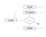
- FIG. 1 is a schematic diagram schematically showing a configuration example of a determination system disclosed in the present application.
- the determination system disclosed in the present application is installed in facilities such as hospitals, nursing homes, and nursing homes.
- facilities such as hospitals, nursing homes, and nursing homes.
- rooms such as hospital rooms and care rooms for patients who need monitoring, residents, and other people requiring care (subjects), and beds 3 used by people requiring care are placed in the rooms.
- beds 3 used by people requiring care
- there are waiting areas such as nurse stations where staff such as nurses, caregivers, doctors, etc. wait for medical personnel who provide nursing care for people requiring nursing care. .
- a bed 3 used by a person requiring care includes a floorboard 30.
- a mat 31 is placed on the floorboard 30 as bedding. be killed.
- a detection device 1 is attached to the bed 3 .
- the detection device 1 includes a detection unit 10 using a sheet-like piezoelectric sensor 10a (see FIG. 2, etc.).
- the detection device 1 can detect vibrations in various frequency ranges generated by the person requiring care. Therefore, the signal output from the detection device 1 is a signal in which a plurality of vibrations having various frequency characteristics are superimposed on each other.
- the detection device 1 detects at least one of a body sound signal with a frequency of 20 Hz or higher, a heartbeat signal, a respiratory vibration signal, a body movement signal with a frequency of 20 Hz or lower, and a snoring signal with a frequency of 20 Hz or higher. It may be possible to obtain A body sound signal with a frequency of 20 Hz or more and a snoring signal with a frequency of 20 Hz or more can be distinguished based on the frequency component (spectrum).
- the detection unit 10 of the detection device 1 is laid, for example, under bedding such as the mat 31 and sheets of the bed 3 used by the person requiring care. That is, the detection unit 10 performs detection regarding the subject through bedding such as the mat 31 and sheets.
- FIG. 1 illustrates a configuration in which the detector 10 is placed on the floor plate 30 of the bed 3 and the mat 31 is placed thereon. Note that the detection unit 10 may be placed on a sheet so as to come into direct contact with the person requiring care.
- a determination device 2 is connected to the detection device 1, and an electrical signal output from the detection device 1 is input to the determination device 2 via a communication line. It is also possible to communicate between the detection device 1 and the determination device 2 by wireless communication based on a wireless communication standard such as Bluetooth (registered trademark).
- the determination device 2 As devices capable of communicating with the determination device 2, there are various communication devices 4 such as a nurse call receiving device possessed by a nurse, a monitor deployed at a nurse station, a mobile phone, a smart phone, a tablet type terminal held by an external party. used.
- the determination device 2 and the communication device 4 are communicably connected by a communication network NW such as a wireless LAN (Local Area Network), a wired LAN, a WAN (Wide Area Network), and a dedicated communication line.
- the determination device 2 transmits various types of information such as notification information resulting from processing such as determination processing to be described later to the communication device 4 via the communication network NW. Transmission of various types of information from the determination device 2 to the communication device 4 may be of a push type that transmits information in substantially real time.
- FIG. 2 is a block diagram showing a configuration example of a device such as the detection device 1 included in the determination system disclosed in the present application.
- the detection device 1 includes various components such as an amplitude amplifier 11, a preprocessing LPF (Low Pass Filter) 12, an output section 13, and the like, in addition to the detection section 10 using a sensor.
- LPF Low Pass Filter
- the detection unit 10 has a function of detecting waves such as sound and vibration with the piezoelectric sensor 10a, converting the detected waves into analog electrical signals, and outputting them to the amplitude amplifier 11.
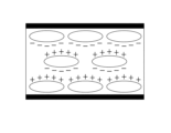
- 3A and 3B are schematic diagrams conceptually showing an example of a piezoelectric sensor 10a used in the detection unit 10 of the detection device 1 included in the determination system disclosed in the present application.
- 3A and 3B schematically show a cross section of the piezoelectric sensor 10a, with FIG. 3A showing a state without pressure and FIG. 3B showing a state with pressure.
- the piezoelectric sensor 10a is formed in a sheet shape using an electret foam using a polyolefin material having an ultra-dense foam structure.
- the piezoelectric sensor 10a When the piezoelectric sensor 10a receives pressure, it transitions from the state shown in FIG. 3A to the state shown in FIG. 3B, and the internal bubbles are deformed to generate a potential difference. The generated potential difference is output to the amplitude amplifier 11 as an analog electrical signal.
- an electret sheet used for such a piezoelectric sensor 10a for example, an electret sheet described in Japanese Patent No. 5926860 of the present applicant is used.
- the amplitude amplifier 11 is configured using, for example, a signal amplification amplifier that amplifies the voltage of the electrical signal.
- the amplitude amplifier 11 amplifies the amplitude of the wave voltage received as an analog electric signal and outputs it to the preprocessing LPF 12 .
- the preprocessing LPF 12 removes high-frequency noise such as hum noise from the amplified wave and outputs it to the output unit 13 .
- the preprocessing LPF 12 preferably removes analog electrical signals in a frequency band higher than 5 Hz. Furthermore, it is more preferable that the preprocessing LPF 12 remove analog electrical signals in a frequency band higher than 10 Hz and pass analog electrical signals in a frequency band of 10 Hz or lower.
- the output unit 13 outputs the analog electrical signal that has passed through the preprocessing LPF 12 to the determination device 2 .
- the amplitude amplifier 11 and the preprocessing LPF 12 are circuits that perform preprocessing to convert the input electrical signal into an electrical signal that can be processed by the determination device 2. Even after amplitude amplification and high-frequency noise removal, the electrical signal The waveform shape of is maintained. That is, the detection device 1 outputs an electric signal having a signal waveform in a state of so-called raw data detected by the detection unit 10 to the determination device 2 .
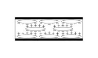
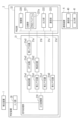
- FIG. 4 is a block diagram showing a configuration example of devices such as the determination device 2 and the communication device 4 included in the determination system disclosed in the present application.
- the determination device 2 is configured by mounting various electric circuits and a microcomputer (microcomputer), for example.
- the determination device 2 includes various components such as an input unit 20, a signal processing unit 21, a determination unit 22, and the like.
- the input unit 20 is an input unit that receives the input of analog electrical signals output from the detection device 1 .
- the signal processing unit 21 is a unit that processes the received electrical signal or outputs it to the determination unit 22 without processing.
- the signal processing unit 21 includes an A/D conversion unit 210 that converts the analog electrical signal received by the input unit 20 into a digital electrical signal, and has multiple routes for processing the converted digital electrical signal.
- the A/D converter 210 samples the analog electric signal at a sampling period of 100 Hz, for example, and converts it into a digital signal.
- the first route 21a is a route for performing signal processing for detecting the heartbeat signal of the subject, and includes circuits such as a detection circuit 21a1, a HPF (High Pass Filter) circuit 21a2, and a first LPF circuit 21a3.
- the HPF circuit 21a2 is, for example, a circuit that removes electrical signals in a frequency band of 0.01 Hz or less, and more preferably a circuit that removes electrical signals in a frequency band of 0.6 Hz or less.
- the HPF circuit 21a2 passes electrical signals in a frequency band higher than 0.01 Hz when removing electrical signals in a frequency band of 0.01 Hz or less, and passes 0 when removing electrical signals in a frequency band of 0.6 Hz or less.
- the first LPF circuit 21a3 is, for example, a circuit that removes electrical signals in a frequency band higher than 4.0 Hz, and more preferably a circuit that removes electrical signals in a frequency band higher than 2.2 Hz.
- the first LPF circuit 21a3 passes electrical signals in a frequency band of 4.0 Hz or less when removing electrical signals in a frequency band higher than 4.0 Hz, and when removing electrical signals in a frequency band higher than 2.2 Hz, It passes electrical signals in a frequency band of 2.2 Hz or less.
- the electrical signal that has passed through the first route 21 a is output to the determination section 22 .
- the second route 21b is a route for performing signal processing for detecting that the subject is in the middle of the sitting-up motion or has finished the sitting-up motion, and circuits such as the second LPF circuit 21b1 and the detection circuit 21b2 are used. contains.
- the second LPF circuit 21b1 is, for example, a circuit that removes electrical signals in a frequency band higher than 10 Hz, and more preferably a circuit that removes electrical signals in a frequency band higher than 1 Hz.
- the second LPF circuit 21b1 passes electrical signals in the frequency band of 10 Hz or lower when removing electrical signals in the frequency band higher than 10 Hz, and passes electrical signals in the frequency band of 1 Hz or lower when removing electrical signals in the frequency band higher than 1 Hz. pass electrical signals.
- the electrical signal that has passed through the second route 21 b is output to the determination section 22 .
- the third route 21c is a route for performing signal processing for detecting the respiratory signal of the subject, and includes circuits such as the third LPF circuit 21c1.
- the third LPF circuit 21c1 is, for example, a circuit that removes electrical signals in a frequency band higher than 2.0 Hz, and more preferably a circuit that removes electrical signals in a frequency band higher than 0.5 Hz.
- the third LPF circuit 21c1 passes electrical signals in a frequency band of 2.0 Hz or lower when removing electrical signals in a frequency band higher than 2.0 Hz, and removes electrical signals in a frequency band higher than 0.5 Hz. It allows electrical signals in a frequency band of 0.5 Hz or less to pass through.
- the electrical signal that has passed through the third route 21 c is output to the determination section 22 .
- the fourth route 21d is a route for performing signal processing for detecting that the body position of the subject has started a rising motion that transitions from the lying position to the sitting position. 22.
- the electrical signal passing through the fourth route 21d is an electrical signal in which the shape of the signal waveform of the digital electrical signal converted by the A/D converter 210 is maintained.
- Various circuits included in the signal processing unit 21 can be configured in various forms such as hardware, software, and a hybrid circuit of hardware and software.
- the determination unit 22 is configured using, for example, a microcomputer equipped with a semiconductor chip such as VLSI (Very Large-Scale IC), and includes a control unit 220, a recording unit 221, an output unit 222, and a communication unit. 223 or the like.
- VLSI Very Large-Scale IC
- the control unit 220 is a processor that includes various circuits such as an information processing circuit, a timer circuit, and a register circuit, and executes processing for overall control.
- the recording unit 221 is a circuit configured using nonvolatile memory and volatile memory, and records various data such as various programs and various reference values.
- a program recorded in the recording unit 221 a program such as a determination program 221a for performing determination processing can be exemplified.
- Examples of the reference values recorded in the recording unit 221 include various reference values such as an upper limit reference value, a lower limit reference value, and a time reference value used in the determination process.
- the determination device 2 By the control unit 220 executing various steps included in the determination program 221a recorded in the recording unit 221, the determination device 2 detects the state of the subject from the digital electric signal based on the wave detected by the detection unit 10. Demonstrate the ability to judge.
- the output unit 222 is an output unit such as a liquid crystal display and a speaker.
- the communication unit 223 is a communication unit including various configurations such as an antenna, a LAN adapter, a control circuit, etc. for wireless or wired communication with the communication device 4 via the communication network NW.
- the communication device 4 includes a communication unit 40 that communicates with the determination device 2 via the communication network NW, an output unit 41 that performs various outputs, and the like.
- the output by the output unit 41 includes processes such as light output, image display, sound output, ringing, and vibration.
- FIG. 5 is a flowchart showing an example of detection processing of the detection device 1 included in the determination system disclosed in the present application.
- the detection unit 10 of the detection device 1 detects waves such as vibrations of the subject with the piezoelectric sensor 10a (S101), and converts the detected waves into analog electric signals.
- the detection device 1 amplifies the amplitude of the analog electrical signal by the amplitude amplifier 11 (S102), and removes high frequency noise by the preprocessing LPF 12 (S103).
- the detection device 1 outputs the analog electrical signal to the determination device 2 through the output unit 13 (S104).
- the detection device 1 executes detection processing.
- FIG. 6 is a flowchart showing an example of signal processing of the determination device 2 included in the determination system disclosed in the present application.
- the determination device 2 receives an input of an analog electrical signal from the detection device 1 through the input unit 20 (S201).
- the signal processing unit 21 of the determination device 2 converts into a digital electrical signal in the A/D conversion unit 210 (S202). Further, the signal processing unit 21 processes the digital electric signal or outputs it to the determination unit 22 without processing (S203).
- step S203 the signal processing unit 21 performs signal processing for extracting a signal in a specific frequency band from the digital electric signals passing through the first route 21a to the third route 21c, and extracts the digital electric signals passing through the fourth route 21d.
- the signal is output to the determination unit 22 as unprocessed data that maintains the signal waveform.
- the detection device 1 executes signal processing.
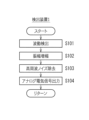
- FIG. 7 is a flowchart showing an example of determination processing of the determination device 2 included in the determination system disclosed in the present application.
- the determination unit 22 of the determination device 2 performs processing for determining the heartbeat state of the subject based on the digital electrical signal that has passed through the first route 21a. Further, the determination unit 22 determines the state of the signal for detecting that the subject is in the middle of the sitting-up motion or has finished the sitting-up motion, based on the digital electric signal that has passed through the second route 21b. process. Further, the determination unit 22 performs processing for determining the respiratory state of the subject based on the digital electrical signal that has passed through the third route 21c.
- the determination unit 22 determines whether the subject transitions from the lying position to the sitting position with respect to the digital electric signal that has passed through the fourth route 21d, that is, the digital electric signal that maintains the shape of the waveform of the electric signal output by the detection unit 10. A process for determining whether or not the rising motion to be performed is started. Furthermore, the determination unit 22 integrates the digital electrical signals that have passed through the first route 21a, the second route 21b, and the third route 21c, and determines the state of the subject's posture, for example, the lying position, sitting position, etc. process. With reference to FIG. 7, the determination processing for determining whether or not the rising motion for transitioning from the lying position to the sitting position has started will be described.
- the control unit 220 included in the determination unit 22 of the determination device 2 executes the determination process by executing the determination program 221a recorded in the recording unit 221 .
- the control unit 220 calculates a moving average value of the signal values of the digital electrical signal received through the fourth route 21d (S301).
- a moving average value is calculated for a period of 5 seconds or less. It should be noted that it is not preferable to lengthen the period for which the moving average is to be applied, since promptness is required for the determination of the start of the sitting-up motion. Further, for determination processing in which promptness is emphasized, the calculation of the moving average in step S301 may be omitted, and the processing after step S302 described below may be executed. That is, the process of step S301 is executed when the demand for promptness is low. The higher the demand for promptness, the shorter the target period. It is preferable to use the signal value of the digital electrical signal omitting the calculation of the average.
- the control unit 220 determines whether or not the subject is in the supine position, ie, is lying on the bed 3 (S302). The determination itself as to whether or not the subject is in the supine position is performed based on digital electrical signals that have passed through other routes such as the first route 21a. In step S302, for example, the method of determining the lying position described in International Publication No. 2021/112131 filed by the applicant of the present application is used.
- step S302 If it is determined in step S302 that the person is in the supine position (S302: YES), the control unit 220 determines that the signal value of the digital electrical signal is equal to or higher than the predetermined upper reference value or lower limit reference value or lower recorded in the recording unit 221. (S303). The upper limit reference value and the lower limit reference value are recorded in advance in the recording unit 221 as state determination conditions.
- step S303 If it is determined in step S303 that the signal value is equal to or greater than the predetermined upper reference value or equal to or lower than the lower reference value (S303: YES), the control unit 220 continues to maintain the state equal to or higher than the upper reference value or equal to or lower than the lower limit value. It is determined whether or not the current duration exceeds the time reference value recorded in the recording unit 221 (S304). In step S304, the signal value may momentarily fluctuate due to factors such as noise. Even when the state exceeds the lower limit reference value, if the state is equal to or less than the predetermined instantaneous reference value, the control unit 220 continues the state of being equal to or more than the upper limit reference value or equal to or less than the lower limit reference value. You may set so that it may determine.
- the state of the upper limit reference value or more is instantaneously switched to the state of the lower limit value or less, the same applies when the signal value in the middle of the switching is detected. It may be set so as to determine whether or not the state of above or below the lower reference value continues.
- Reference values such as the upper limit reference value and the lower limit reference value that serve as the judgment reference in step S303, and the time reference value and the instantaneous reference value that serve as the judgment reference in step S304 are recorded in the recording unit 221 in advance as the state judgment conditions. It is to be noted that
- step S304 If it is determined in step S304 that the time during which the signal value continues to be equal to or greater than the upper limit reference value or equal to or less than the lower limit value exceeds the time reference value recorded in the recording unit 221 (S304: YES), control The unit 220 determines that the state determination condition is satisfied, and that the state of the subject is a state in which the subject has started a rising motion that transitions from the lying position to the sitting position (S305).
- the control unit 220 which has determined that the state determination conditions are satisfied and the subject has started the sit-up motion to transition from the lying position to the sitting position, performs notification processing for notifying the start of the sit-up motion (S306). ).
- the notification processing in step S306 includes processing for outputting notification information for notifying the start of the standing-up motion from the output unit 222, processing for transmitting from the communication unit 223 to the communication device 4 via the communication network NW, and the like.
- a recording process for recording for example, in the recording unit 221 that the state determination condition is satisfied may be executed together with the notification process or instead of the notification process.
- step S302 If it is determined in step S302 that the position is not in the supine position (S302: NO), if it is determined in step S303 that the signal value is below the upper limit reference value and above the lower limit reference value (S303: NO), or step S304 , if it is determined that the duration time does not exceed the time reference value (S304: NO), the control unit 220 does not satisfy the state determination condition, and the state of the subject changes from the lying position to the sitting position. It is determined that the operation has not started (S307).
- the control unit 220 determines that the state determination condition is not satisfied and the subject's state is not in a state of starting a rising motion that transitions from the lying position to the sitting position. is taken in, the process returns to step S301, and the subsequent processes are repeated.
- the determination processing of the determination device 2 is executed. Note that the determination processing of the determination device 2 explained with reference to FIG. 21c for digital electrical signals. In other words, the determination processing of the determination device 2 can also be performed on an electrical signal that has passed through circuits such as the first LPF circuit 21a3, the second LPF circuit 21b1, and the third LPF circuit 21c1.
- the communication device 4 When the communication unit 40 receives notification information transmitted from the determination device 2 via the communication network NW, the communication device 4 outputs the received notification information from the output unit 41 .
- the output of notification information is light output, image display, and voice output from various communication devices 4 such as a nurse call receiving device possessed by a nurse, a monitor deployed at a nurse station, and a mobile phone possessed by an external party. output, ringing, vibration, etc.
- Staff members such as nurses, caregivers, doctors, and related parties such as family members who have confirmed the notification information output from the communication device 4 can take appropriate measures according to the condition of the target person.
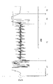
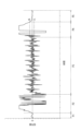
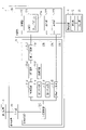
- FIG. 8 is a graph showing an example of the waveform of the digital electric signal input to the determination unit 22 of the determination device 2 included in the determination system disclosed in the present application.
- the horizontal axis represents time and the vertical axis represents the signal value of the digital electrical signal, showing the change over time of the signal value of the digital electrical signal that has passed through the fourth route 21d.
- P1 is the period in which the subject is out of bed
- P2 is the period in which the subject is moving into bed
- P3 is the period in which the subject is in the lying position
- P4 is the period in which the subject is lying
- P5 indicates the period in which the subject is in the sitting position, and the period in which the subject is in the sitting position.
- the dashed-dotted line in the drawing indicates the upper limit reference value (denoted as UL in the drawing) and the lower limit reference value (denoted as LL in the drawing).
- the signal value of the digital electric signal is stable within the upper limit reference value and the lower limit reference value during the period P3 in which the subject is in the lying position after entering the bed. Then, during the period P4 in which the subject performs the sitting-up motion, the signal value changes significantly between positive and negative, and the state continues to exceed the range between the upper limit reference value and the lower limit reference value. Therefore, by appropriately setting the upper limit reference value, the lower limit reference value, and the time reference value, it is possible to detect the state in which the sitting-up motion has started.
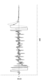
- FIG. 9 is a graph showing an example of the waveform of the digital electric signal input to the determination unit 22 of the determination device 2 included in the determination system disclosed in the present application.
- FIG. 9 shows a form in which the setting of the upper limit reference value and the lower limit reference value illustrated in FIG. 8 is changed so that the upper limit reference value is lowered and the lower limit reference is raised.
- the setting as shown in FIG. 9 it is possible to determine the initial motion of getting up more quickly than the configuration shown in FIG.
- the upper limit reference value and the lower limit reference value are appropriately changed according to the implementation environment such as the situation at the time of implementation and the condition of the subject.
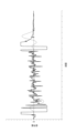
- FIG. 10 is a graph showing an example of the waveform of the digital electric signal input to the determination unit 22 of the determination device 2 included in the determination system disclosed in the present application.
- the abscissa represents time and the ordinate represents the signal value of the digital electric signal, showing changes over time in the signal value.
- the waveform of the digital electrical signal of the raw data indicated by the solid line is superimposed for comparison with the waveform of the digital electrical signal through the LPF that removes the signal value in the frequency band higher than 1 Hz indicated by the dashed line.
- the waveform of the digital electrical signal passed through the 1 Hz LPF has a delayed peak occurrence where the signal value increases positively and negatively, and the time over which the upper and lower reference values are exceeded is shorter. .
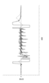
- FIG. 11 is a graph showing an example of the waveform of the digital electric signal input to the determination unit 22 of the determination device 2 included in the determination system disclosed in the present application.
- the horizontal axis represents time and the vertical axis represents the signal value of the digital electric signal, showing changes over time in the signal value.
- the waveform of the digital electrical signal of the raw data indicated by the solid line is superimposed for comparison with the waveform of the digital electrical signal through the LPF that removes the signal value in the frequency band higher than 0.5 Hz indicated by the dashed line. are doing.
- the waveform of the digital electrical signal passed through the LPF of 0.5 Hz has a delay in the occurrence of peaks where the signal value increases positively and negatively, and the maximum positive and negative values are small.
- FIG. 12 is a graph showing an example of the waveform of the digital electric signal input to the determination unit 22 of the determination device 2 included in the determination system disclosed in the present application.
- the horizontal axis represents time and the vertical axis represents the signal value of the digital electric signal, showing changes in signal value over time.
- the waveform of the digital electrical signal of the raw data indicated by the solid line is superimposed on the waveform of the digital electrical signal obtained by calculating the moving average indicated by the dashed line for comparison.
- the moving average in FIG. 12 indicates the average value of 100 signal values at 100 Hz, that is, the calculated value of the moving average for 1 sec.
- the 1-sec moving average waveform has a slower occurrence of peaks where the signal value increases positively and negatively, and the time over which the upper and lower reference values are exceeded is shorter.
- FIG. 13 is a graph showing an example of the waveform of the digital electric signal input to the determination unit 22 of the determination device 2 included in the determination system disclosed in the present application.
- the horizontal axis represents time and the vertical axis represents the signal value of the digital electric signal, showing changes in the signal value over time.
- the waveform of the digital electric signal of raw data indicated by the solid line is superimposed on the waveform of the digital electric signal obtained by calculating the moving average indicated by the dashed line for comparison.
- the moving average in FIG. 13 indicates the average value of 200 signal values at 100 Hz, that is, the calculated value of the moving average for 2 seconds.
- the 2-second moving average waveform has a slower occurrence of peaks where the signal value increases positively and negatively, and the time over which the upper and lower reference values are exceeded is shorter.
- the digital electrical signal to be subjected to the determination process can be obtained quickly when raw data related to the signal waveform that maintains the shape of the waveform of the electrical signal output by the detection unit 10 is used. judgment is possible. Further, as illustrated in FIGS. 10 to 13, the digital electrical signal to be subjected to the determination process may be an electrical signal such as a digital electrical signal passed through an LPF or a moving averaged digital electrical signal. be.
- the configuration example of the determination system disclosed in the present application is not limited to the configuration illustrated in FIG. 1, etc., and the hardware configuration and software processing can be designed as appropriate. That is, the determination system disclosed in the present application has at least a detection function for detecting waves generated based on the subject, a signal processing function for performing signal processing on an electrical signal based on the detected waves, and a digital electrical signal to detect the subject's It can be realized as various configurations having a judgment function for judging the state.
- FIG. 14 is a schematic block diagram showing a configuration example of the determination system disclosed in the present application.
- FIG. 14 shows an outline of another configuration example of the determination system.
- the determination system shown in FIG. 14 includes a detection device 1 , a determination device 2 and a communication device 4 , and further includes a signal processing device 5 .
- the signal processing device 5 has a form in which circuits related to signal processing such as the signal processing unit 21 provided in the determination device 2 are mounted as independent devices, and is configured using a semiconductor chip such as VLSI.
- the signal processing device 5 may further incorporate the preprocessing LPF 12 included in the detection device 1 .
- a general-purpose computer such as a personal computer.
- the determination system according to system configuration example 1 has a form in which the signal processing-related functions of the determination device 2 are made independent as the signal processing device 5 .
- FIG. 15 is a schematic block diagram showing a configuration example of the determination system disclosed in the present application.
- FIG. 15 shows an outline of still another configuration example of the determination system.
- a system configuration example 2 is configured using a server computer that connects the determination device 2 to the communication network NW.
- the signal processing device 5 includes circuits related to signal processing such as the signal processing unit 21, and performs processing for transmitting the processed digital electrical signal to the determination device 2 on the communication network NW.
- the determination device 2 executes various processes such as determination processing based on the received digital electric signal, and transmits notification information based on the determined result to the communication device 4 via the communication network NW.
- a communication device 4 configured using devices such as a nurse call receiver, a monitor, and a mobile phone performs output processing such as display of information indicating the subject's condition and output of voice based on the information indicating the received result. I do.
- the configuration example of the determination device 2 included in the determination system disclosed in the present application is also not limited to the configuration illustrated in FIG. 4 and the like, and can be designed as appropriate.
- the determination device 2 disclosed in the present application which has been described with reference to FIG. This is the output format.
- the determination device 2 disclosed in the present application can also be developed in a form in which an electrical signal passing through the fourth route 21d is processed and output to the determination unit 22, as illustrated below.
- FIG. 16 is a block diagram showing a configuration example of a device such as the determination device 2 included in the determination system disclosed in the present application.
- Another configuration example 1 illustrated in FIG. 16 is a configuration example in which the design of the fourth route 21d included in the signal processing unit 21 of the determination device 2 is changed in the configuration example illustrated in FIG.
- the above description shall be referred to, and detailed description thereof will be omitted.
- the fourth route 21d is a configuration example including a noise elimination circuit 21d1.
- the noise elimination circuit 21d1 is a circuit that eliminates hum noise of 10 Hz or higher.
- FIG. 17 is a block diagram showing a configuration example of a device such as the determination device 2 included in the determination system disclosed in the present application.
- Another configuration example 2 illustrated in FIG. 17 has a configuration in which a fourth LPF circuit 21d2 is included in the fourth route 21d in the configuration example illustrated in FIG.
- the configuration other than the fourth route 21d is the same as the configuration example described above with reference to FIG.
- the fourth LPF circuit 21d2 is, for example, a circuit that removes electrical signals in a frequency band higher than 4 Hz and passes electrical signals in a frequency band of 4 Hz or lower.
- the determination device 2 can improve the determination accuracy and suppress erroneous determination. While the third LPF circuit 21c1 removes electrical signals in a frequency band higher than 0.5 Hz, the fourth LPF circuit 21d2 removes electrical signals in a frequency band higher than 3 Hz. Therefore, the electrical signal that has passed through the fourth route 21d is an electrical signal that maintains the original waveform compared to the electrical signal that has passed through the third route 21c.
- FIG. 18 is a block diagram showing a configuration example of a device such as the determination device 2 included in the determination system disclosed in the present application.
- Another configuration example 3 illustrated in FIG. 18 has a configuration in which a moving average circuit 21d3 is included in the fourth route 21d in the configuration example illustrated in FIG.
- the configuration other than the fourth route 21d is the same as the configuration example described above with reference to FIG.
- the moving average circuit 21d3 is a circuit that takes a moving average in a unit time set to 5 sec or less and outputs the digital electric signal that has received its input. By arranging the moving average circuit 21d3 on the fourth route 21d, the determination device 2 can improve the determination accuracy and suppress erroneous determination.
- determination device 2 can be implemented in combination as appropriate.
- other configuration examples of the determination device 2 include a configuration in which a noise elimination circuit 21d1 and a fourth LPF circuit 21d2 are arranged in the fourth route 21d, a configuration in which a noise elimination circuit 21d1 and a moving average circuit 21d3 are arranged, and the like. It can be deployed in various configurations.
- the determination system disclosed in the present application detects the wave motion of the subject, and when the time period of the state of the predetermined upper reference value or more or the lower limit reference value or less exceeds the predetermined time reference value, the subject is standing up. is determined to have started and annunciated. As a result, it is possible to detect early the start of the sitting-up motion, which is likely to cause an accident, and to take measures such as assistance.
- both the upper limit reference value and the lower limit reference value are set as the state determination conditions, but the present invention is not limited to this, and only one of the upper limit reference value and the lower limit reference value is set. It is possible to expand into various forms, such as setting as a state determination condition.
- a form was shown in which the time in the state of the upper limit reference value or more or the lower limit reference value or less was collectively compared with the reference time.
- Various forms can be developed, such as setting a reference time for each value.
- the present invention is not limited to this, and a microphone sensor may be used as long as it is possible to detect waves. It is possible to use various sensors such as.
- detection unit 10 detection unit 10a piezoelectric sensor 2 determination device 22 determination unit 220 control unit 221 recording unit 221a determination program 3 bed 30 floorboard 31 mat 4 communication device 5 signal processing device
Landscapes
- Health & Medical Sciences (AREA)
- Life Sciences & Earth Sciences (AREA)
- Veterinary Medicine (AREA)
- Physics & Mathematics (AREA)
- Public Health (AREA)
- General Health & Medical Sciences (AREA)
- Animal Behavior & Ethology (AREA)
- Pathology (AREA)
- Molecular Biology (AREA)
- Engineering & Computer Science (AREA)
- Biomedical Technology (AREA)
- Heart & Thoracic Surgery (AREA)
- Surgery (AREA)
- Medical Informatics (AREA)
- Biophysics (AREA)
- Oral & Maxillofacial Surgery (AREA)
- Dentistry (AREA)
- Physiology (AREA)
- General Physics & Mathematics (AREA)
- Nursing (AREA)
- Measurement Of The Respiration, Hearing Ability, Form, And Blood Characteristics Of Living Organisms (AREA)
- Invalid Beds And Related Equipment (AREA)
- Measuring And Recording Apparatus For Diagnosis (AREA)
- Accommodation For Nursing Or Treatment Tables (AREA)
- Medical Treatment And Welfare Office Work (AREA)
- Debugging And Monitoring (AREA)
Abstract
Description
本願開示の判定システムは、検出装置、判定装置等の各種装置を用いたシステムであり、対象者の状態、例えば、呼吸の状態、心拍の状態、姿勢の状態等の状態の検知を目的として用いられる。姿勢の状態としては、例えば、臥位、座位等の姿勢を例示することができる。本願では、臥位から座位へ遷移する際の初動、即ち、起き上がり動作を開始した状態の検知等の目的に用いた形態を主として説明する。以下では、図面を参照しながら、図面に例示された検出装置1、判定装置2等の装置の具体例について説明する。なお、以下の実施形態は、本発明を具現化した一例であって、本発明の技術的範囲を限定する性格のものではない。
図1は、本願開示の判定システムの構成例を模式的に示す概略図である。本願開示の判定システムは、病院、老人ホーム、介護施設等の施設内に設置される。施設内には、モニタリングを要する患者、入居者等の要介護者(対象者)が入る病室、介護室等の部屋が設置されており、部屋内には要介護者が使用するベッド3が配置されている。また、施設内には、要介護者の看護、介護等のケアを行う医療関係者等、例えば、看護師、介護士、医師等の職員が待機するナースステーション等の待機所が設置されている。
次に、本願開示の判定システムが備える各種装置のハードウェア構成について説明する。図2は、本願開示の判定システムが備える検出装置1等の装置の構成例を示すブロック図である。検出装置1は、センサを用いた前述の検出部10の他、振幅増幅器11、前処理LPF(Low Pass Filter )12、出力部13等の各種構成を備えている。なお、本願では、検出部10が備えるセンサの一例として、シート状の圧電センサ10aを用いた形態を例示して説明する。
次に、本願開示の判定システムにおける各種装置の処理について説明する。図5は、本願開示の判定システムが備える検出装置1の検出処理の一例を示すフローチャートである。検出装置1の検出部10は、圧電センサ10aにて、対象者に関する振動等の波動を検出し(S101)、検出した波動をアナログ電気信号に変換する。検出装置1は、振幅増幅器11により、アナログ電気信号の振幅を増幅し(S102)、前処理LPF12により、高周波ノイズを除去する(S103)。検出装置1は、出力部13により、アナログ電気信号を判定装置2へ出力する(S104)。
次に、本願開示の判定システムの実施例について説明する。図8は、本願開示の判定システムが備える判定装置2の判定部22に入力されるデジタル電気信号の波形の一例を示すグラフである。図8は、横軸に時間をとり、縦軸にデジタル電気信号の信号値をとって、第4ルート21dを通ったデジタル電気信号の信号値の経時変化を示している。図中、P1は、対象者が離床状態にある期間、P2は、対象者が入床動作をしている期間、P3は、対象者が臥位状態にある期間、P4は、対象者が臥位から座位へ遷移する起き上がり動作を行っている期間、そして、P5は、対象者が座位状態にある期間を示している。また、図中一点鎖線は、上限基準値(図中ULと表記)及び下限基準値(図中LLと表記)を示している。
図14は、本願開示の判定システムの構成例を示す概略ブロック図である。図14は、判定システムの他の構成例の概略を示している。図14に記載の判定システムは、検出装置1、判定装置2及び通信装置4を備えており、更に、信号処理装置5を備えている。信号処理装置5は、判定装置2が備える信号処理部21等の信号処理に関する回路を独立した装置として実装した形態であり、VLSI等の半導体チップを用いて構成されている。信号処理装置5には、更に、検出装置1が備える前処理LPF12を組み込むようにしてもよい。更に、信号処理に関する構成を信号処理装置5として独立させることにより、パーソナルコンピュータ等の汎用型のコンピュータを用いて判定装置2を構成することも可能である。
図15は、本願開示の判定システムの構成例を示す概略ブロック図である。図15は、判定システムの更に他の構成例の概略を示している。システム構成例2は、判定装置2を通信網NWに接続するサーバコンピュータを用いて構成した形態である。システム構成例2において、信号処理装置5は、信号処理部21等の信号処理に関する回路を備えており、処理後のデジタル電気信号を、通信網NW上の判定装置2へ送信する処理を行う。判定装置2は、受信したデジタル電気信号に基づく判定処理等の各種処理を実行して、判定した結果に基づく報知情報を、通信網NWを介して通信装置4へ送信する。ナースコール受信装置、モニタ、携帯電話等の装置を用いて構成された通信装置4は、受信した結果を示す情報に基づいて、対象者の状態を示す情報の表示、音声の出力等の出力処理を行う。
図16は、本願開示の判定システムが備える判定装置2等の装置の構成例を示すブロック図である。図16に例示する他の構成例1は、図4に例示する構成例において、判定装置2の信号処理部21が備える第4ルート21dの設計を変更した構成例である。第4ルート21d以外の構成については、前述の説明を参照するものとし、詳細な説明を省略する。
図17は、本願開示の判定システムが備える判定装置2等の装置の構成例を示すブロック図である。図17に例示する他の構成例2は、図4に例示する構成例において、第4ルート21dに、第4LPF回路21d2を含んだ構成となっている。第4ルート21d以外の構成については、図4を用いて説明した前述の構成例と同様である。第4LPF回路21d2は、例えば、4Hzより高い周波数帯の電気信号を除去し、4Hz以下の周波数帯の電気信号を通過させる回路である。第4ルート21dに第4LPF回路21d2を配置することにより、判定装置2は、判定制度を向上させ、誤判定を抑制することが可能となる。なお、第3LPF回路21c1が0.5Hzより高い周波数帯の電気信号を除去するのに対し、第4LPF回路21d2は、3Hzより高い周波数帯の電気信号を除去する。従って、第4ルート21dを通った電気信号の方が、第3ルート21cを通った電気信号と比べて、元の波形を維持した電気信号となる。
図18は、本願開示の判定システムが備える判定装置2等の装置の構成例を示すブロック図である。図18に例示する他の構成例3は、図4に例示する構成例において、第4ルート21dに、移動平均回路21d3を含んだ構成となっている。第4ルート21d以外の構成については、図4を用いて説明した前述の構成例と同様である。移動平均回路21d3は、入力を受け付けたデジタル電気信号に対し、5sec以下に設定された単位時間における移動平均をとって出力する回路である。第4ルート21dに移動平均回路21d3を配置することにより、判定装置2は、判定制度を向上させ、誤判定を抑制することが可能となる。
10 検出部
10a 圧電センサ
2 判定装置
22 判定部
220 制御部
221 記録部
221a 判定プログラム
3 ベッド
30 床板
31 マット
4 通信装置
5 信号処理装置
Claims (11)
- 対象者に基づき発生する波動を検出し、検出した波動に基づく電気信号を出力する検出部と、
前記検出部が出力した電気信号に係る信号値について、所定の上限基準値以上又は下限基準値以下の状態の時間が所定の時間基準値を超える状態判定条件を充足する場合に、対象者が起き上がり動作を開始したと判定する判定部と
を備えることを特徴とする判定システム。 - 請求項1に記載の判定システムであって、
前記判定部は、対象者の体位が、臥位であると判定している状態から、前記状態判定条件を充足した場合に、対象者が臥位から座位へ遷移する起き上がり動作を開始したと判定する
ことを特徴とする判定システム。 - 請求項1又は請求項2に記載の判定システムであって、
前記信号値は、前記検出部が出力した電気信号の波形の形状を維持した信号波形に係る値である
ことを特徴とする判定システム。 - 請求項1又は請求項2に記載の判定システムであって、
前記信号値は、前記検出部が出力した電気信号からハムノイズを除去した値である
ことを特徴とする判定システム。 - 請求項1又は請求項2に記載の判定システムであって、
前記信号値は、前記検出部が出力した電気信号から4Hz以下の周波数帯を通過させて得られた信号波形に係る値である
ことを特徴とする判定システム。 - 請求項1又は請求項2に記載の判定システムであって、
前記信号値は、前記検出部が出力した電気信号に基づいて、5sec 以下の期間で移動平均をとった値である
ことを特徴とする判定システム。 - 請求項1又は請求項2に記載の判定システムであって、
前記検出部が出力した電気信号は、アナログ電気信号であり、
前記信号値は、前記アナログ電気信号から変換されたデジタル電気信号に係る値である
ことを特徴とする判定システム。 - 請求項1乃至請求項7のいずれか1項に記載の判定システムであって、
前記検出部は、
シート状に形成された圧電センサを含む
ことを特徴とする判定システム。 - 検出部が、対象者に基づき発生する波動を検出して、検出した波動に基づく電気信号を出力し、
前記検出部が出力した電気信号に係る信号値について、所定の上限基準値以上又は下限基準値以下の状態の時間が所定の時間基準値を超える状態判定条件を充足するか否かを判定する
ことを特徴とする判定方法。 - 対象者に基づき発生する波動の検出に基づく電気信号の入力を受け付ける入力部と、
前記入力部が受け付けた電気信号に係る信号値について、所定の上限基準値以上又は下限基準値以下の状態の時間が所定の時間基準値を超える状態判定条件を充足する否かを判定する判定部と
を備える判定装置。 - コンピュータに、対象者の状態を判定させる判定プログラムであって、
コンピュータに、
対象者に基づき発生する波動に基づく信号値の入力を受け付ける入力ステップと、
入力を受け付けた信号値について、所定の上限基準値以上又は下限基準値以下の状態の時間が所定の時間基準値を超える状態判定条件を充足する否かを判定する判定ステップと
を実行させる判定プログラム。
Priority Applications (7)
| Application Number | Priority Date | Filing Date | Title |
|---|---|---|---|
| JP2022578846A JP7293516B1 (ja) | 2021-09-22 | 2022-09-20 | 判定システム、判定方法、判定装置及び判定プログラム |
| KR1020247007541A KR20240065073A (ko) | 2021-09-22 | 2022-09-20 | 판정 시스템, 판정 방법, 판정 장치 및 판정 프로그램 |
| EP22872884.6A EP4406523A4 (en) | 2021-09-22 | 2022-09-20 | DETERMINATION SYSTEM, DETERMINATION METHOD, DETERMINATION DEVICE AND DETERMINATION PROGRAM |
| US18/692,947 US20250102536A1 (en) | 2021-09-22 | 2022-09-20 | Determination system, determination method, determination device, and determination program |
| CN202280063820.8A CN117979937A (zh) | 2021-09-22 | 2022-09-20 | 判定系统、判定方法、判定装置以及判定程序 |
| CA3231353A CA3231353A1 (en) | 2021-09-22 | 2022-09-20 | Determination system, determination method, determination device, and determination program |
| JP2023093094A JP2023118712A (ja) | 2021-09-22 | 2023-06-06 | 判定システム、判定方法、判定装置及び判定プログラム |
Applications Claiming Priority (2)
| Application Number | Priority Date | Filing Date | Title |
|---|---|---|---|
| JP2021154639 | 2021-09-22 | ||
| JP2021-154639 | 2021-09-22 |
Publications (1)
| Publication Number | Publication Date |
|---|---|
| WO2023048132A1 true WO2023048132A1 (ja) | 2023-03-30 |
Family
ID=85719507
Family Applications (1)
| Application Number | Title | Priority Date | Filing Date |
|---|---|---|---|
| PCT/JP2022/034958 Ceased WO2023048132A1 (ja) | 2021-09-22 | 2022-09-20 | 判定システム、判定方法、判定装置及び判定プログラム |
Country Status (8)
| Country | Link |
|---|---|
| US (1) | US20250102536A1 (ja) |
| EP (1) | EP4406523A4 (ja) |
| JP (2) | JP7293516B1 (ja) |
| KR (1) | KR20240065073A (ja) |
| CN (1) | CN117979937A (ja) |
| CA (1) | CA3231353A1 (ja) |
| TW (1) | TW202315575A (ja) |
| WO (1) | WO2023048132A1 (ja) |
Families Citing this family (1)
| Publication number | Priority date | Publication date | Assignee | Title |
|---|---|---|---|---|
| JP7576719B1 (ja) | 2024-01-29 | 2024-10-31 | 住友理工株式会社 | 動作判別システム |
Citations (8)
| Publication number | Priority date | Publication date | Assignee | Title |
|---|---|---|---|---|
| JP2015154926A (ja) | 2014-01-17 | 2015-08-27 | 積水化学工業株式会社 | 生体検出システム |
| JP5926860B2 (ja) | 2014-03-13 | 2016-05-25 | 積水化学工業株式会社 | エレクトレットシート及び圧電センサ |
| JP2017184951A (ja) * | 2016-04-04 | 2017-10-12 | タケモトデンキ株式会社 | 静電容量式起き上がりセンサ |
| JP2018094225A (ja) * | 2016-12-15 | 2018-06-21 | 株式会社Z−Works | 生体状態判定システム |
| WO2018135050A1 (ja) * | 2017-01-20 | 2018-07-26 | シャープ株式会社 | 監視装置 |
| JP2018134424A (ja) * | 2012-03-01 | 2018-08-30 | ヘルスセンシング株式会社 | 検出装置 |
| JP2019216961A (ja) * | 2018-06-19 | 2019-12-26 | 藤田 純平 | 健康支援システム |
| WO2021112131A1 (ja) | 2019-12-04 | 2021-06-10 | 積水化学工業株式会社 | 状態判定方法、状態判定装置、状態判定システム、状態判定プログラム及び記録媒体 |
Family Cites Families (1)
| Publication number | Priority date | Publication date | Assignee | Title |
|---|---|---|---|---|
| EP2396776B1 (en) * | 2009-02-13 | 2012-06-13 | Koninklijke Philips Electronics N.V. | Bed monitoring system |
-
2022
- 2022-09-20 JP JP2022578846A patent/JP7293516B1/ja active Active
- 2022-09-20 WO PCT/JP2022/034958 patent/WO2023048132A1/ja not_active Ceased
- 2022-09-20 CN CN202280063820.8A patent/CN117979937A/zh active Pending
- 2022-09-20 CA CA3231353A patent/CA3231353A1/en active Pending
- 2022-09-20 KR KR1020247007541A patent/KR20240065073A/ko active Pending
- 2022-09-20 US US18/692,947 patent/US20250102536A1/en active Pending
- 2022-09-20 EP EP22872884.6A patent/EP4406523A4/en active Pending
- 2022-09-21 TW TW111135673A patent/TW202315575A/zh unknown
-
2023
- 2023-06-06 JP JP2023093094A patent/JP2023118712A/ja active Pending
Patent Citations (8)
| Publication number | Priority date | Publication date | Assignee | Title |
|---|---|---|---|---|
| JP2018134424A (ja) * | 2012-03-01 | 2018-08-30 | ヘルスセンシング株式会社 | 検出装置 |
| JP2015154926A (ja) | 2014-01-17 | 2015-08-27 | 積水化学工業株式会社 | 生体検出システム |
| JP5926860B2 (ja) | 2014-03-13 | 2016-05-25 | 積水化学工業株式会社 | エレクトレットシート及び圧電センサ |
| JP2017184951A (ja) * | 2016-04-04 | 2017-10-12 | タケモトデンキ株式会社 | 静電容量式起き上がりセンサ |
| JP2018094225A (ja) * | 2016-12-15 | 2018-06-21 | 株式会社Z−Works | 生体状態判定システム |
| WO2018135050A1 (ja) * | 2017-01-20 | 2018-07-26 | シャープ株式会社 | 監視装置 |
| JP2019216961A (ja) * | 2018-06-19 | 2019-12-26 | 藤田 純平 | 健康支援システム |
| WO2021112131A1 (ja) | 2019-12-04 | 2021-06-10 | 積水化学工業株式会社 | 状態判定方法、状態判定装置、状態判定システム、状態判定プログラム及び記録媒体 |
Non-Patent Citations (1)
| Title |
|---|
| See also references of EP4406523A4 |
Also Published As
| Publication number | Publication date |
|---|---|
| EP4406523A1 (en) | 2024-07-31 |
| EP4406523A4 (en) | 2025-05-14 |
| KR20240065073A (ko) | 2024-05-14 |
| CA3231353A1 (en) | 2023-03-30 |
| TW202315575A (zh) | 2023-04-16 |
| JP7293516B1 (ja) | 2023-06-19 |
| CN117979937A (zh) | 2024-05-03 |
| JPWO2023048132A1 (ja) | 2023-03-30 |
| US20250102536A1 (en) | 2025-03-27 |
| JP2023118712A (ja) | 2023-08-25 |
Similar Documents
| Publication | Publication Date | Title |
|---|---|---|
| JP5992296B2 (ja) | ナースコールシステム及び状態判断システム | |
| CN107566510B (zh) | 远程医疗诊断服务系统 | |
| JPWO2015037269A1 (ja) | 被監視者監視装置および該方法ならびに被監視者監視システム | |
| JP7628488B2 (ja) | 状態判定方法、状態判定装置、状態判定システム、状態判定プログラム及び記録媒体 | |
| CN102376144A (zh) | 跌倒警报系统 | |
| JP7293516B1 (ja) | 判定システム、判定方法、判定装置及び判定プログラム | |
| JP2008048819A (ja) | 監視システム及び監視装置 | |
| JP2005304942A (ja) | 睡眠状態検出装置 | |
| WO2019022186A1 (ja) | 在床状態監視システム | |
| JP2026002944A (ja) | 排泄検知システム、排泄検知方法、検出装置、排泄検知装置及び排泄検知プログラム | |
| JP3491350B2 (ja) | 就寝装置 | |
| WO2018016392A1 (ja) | 姿勢検出装置及び姿勢検出方法 | |
| CN107496090B (zh) | 多功能的轮椅坐靠背系统和多功能的轮椅坐靠背 | |
| JP7299863B2 (ja) | ベッドシステム及び荷重検出器の取付方法 | |
| JP7259569B2 (ja) | 通知装置、それを備えるシステム、方法、およびプログラム | |
| JP4338770B1 (ja) | 人体異常判別装置 | |
| CN222383192U (zh) | 一种起床报警装置 | |
| JP2020129757A (ja) | 見守り装置および見守り装置用プログラム | |
| JP7338268B2 (ja) | 見守りシステムおよび見守り方法 | |
| WO2017141721A1 (ja) | 端末装置および端末装置の動作制御方法ならびに被監視者監視システム | |
| CN113384294A (zh) | 一种基于声波的准非接触式心率采集装置及使用方法 | |
| JP6757642B2 (ja) | ベッドシステム | |
| JP2025162290A (ja) | 介護映像分析システム、介護映像分析方法、および介護映像分析プログラム | |
| JP2021197075A (ja) | 情報処理装置、制御プログラム、制御システム、および演算方法 | |
| JP2021009070A (ja) | 見守りシステムおよび見守り方法 |
Legal Events
| Date | Code | Title | Description |
|---|---|---|---|
| WWE | Wipo information: entry into national phase |
Ref document number: 2022578846 Country of ref document: JP |
|
| 121 | Ep: the epo has been informed by wipo that ep was designated in this application |
Ref document number: 22872884 Country of ref document: EP Kind code of ref document: A1 |
|
| WWE | Wipo information: entry into national phase |
Ref document number: 3231353 Country of ref document: CA |
|
| WWE | Wipo information: entry into national phase |
Ref document number: 202280063820.8 Country of ref document: CN |
|
| WWE | Wipo information: entry into national phase |
Ref document number: 2022872884 Country of ref document: EP |
|
| NENP | Non-entry into the national phase |
Ref country code: DE |
|
| ENP | Entry into the national phase |
Ref document number: 2022872884 Country of ref document: EP Effective date: 20240422 |
|
| WWP | Wipo information: published in national office |
Ref document number: 18692947 Country of ref document: US |