WO2023053206A1 - 車両用電源システム - Google Patents
車両用電源システム Download PDFInfo
- Publication number
- WO2023053206A1 WO2023053206A1 PCT/JP2021/035641 JP2021035641W WO2023053206A1 WO 2023053206 A1 WO2023053206 A1 WO 2023053206A1 JP 2021035641 W JP2021035641 W JP 2021035641W WO 2023053206 A1 WO2023053206 A1 WO 2023053206A1
- Authority
- WO
- WIPO (PCT)
- Prior art keywords
- battery pack
- converter
- fan
- vehicle
- power supply
- Prior art date
- Legal status (The legal status is an assumption and is not a legal conclusion. Google has not performed a legal analysis and makes no representation as to the accuracy of the status listed.)
- Ceased
Links
Images


Classifications
-
- B—PERFORMING OPERATIONS; TRANSPORTING
- B60—VEHICLES IN GENERAL
- B60L—PROPULSION OF ELECTRICALLY-PROPELLED VEHICLES; SUPPLYING ELECTRIC POWER FOR AUXILIARY EQUIPMENT OF ELECTRICALLY-PROPELLED VEHICLES; ELECTRODYNAMIC BRAKE SYSTEMS FOR VEHICLES IN GENERAL; MAGNETIC SUSPENSION OR LEVITATION FOR VEHICLES; MONITORING OPERATING VARIABLES OF ELECTRICALLY-PROPELLED VEHICLES; ELECTRIC SAFETY DEVICES FOR ELECTRICALLY-PROPELLED VEHICLES
- B60L58/00—Methods or circuit arrangements for monitoring or controlling batteries or fuel cells, specially adapted for electric vehicles
- B60L58/10—Methods or circuit arrangements for monitoring or controlling batteries or fuel cells, specially adapted for electric vehicles for monitoring or controlling batteries
- B60L58/24—Methods or circuit arrangements for monitoring or controlling batteries or fuel cells, specially adapted for electric vehicles for monitoring or controlling batteries for controlling the temperature of batteries
- B60L58/26—Methods or circuit arrangements for monitoring or controlling batteries or fuel cells, specially adapted for electric vehicles for monitoring or controlling batteries for controlling the temperature of batteries by cooling
-
- H—ELECTRICITY
- H01—ELECTRIC ELEMENTS
- H01M—PROCESSES OR MEANS, e.g. BATTERIES, FOR THE DIRECT CONVERSION OF CHEMICAL ENERGY INTO ELECTRICAL ENERGY
- H01M10/00—Secondary cells; Manufacture thereof
- H01M10/60—Heating or cooling; Temperature control
- H01M10/65—Means for temperature control structurally associated with the cells
- H01M10/656—Means for temperature control structurally associated with the cells characterised by the type of heat-exchange fluid
- H01M10/6561—Gases
- H01M10/6563—Gases with forced flow, e.g. by blowers
-
- B—PERFORMING OPERATIONS; TRANSPORTING
- B60—VEHICLES IN GENERAL
- B60K—ARRANGEMENT OR MOUNTING OF PROPULSION UNITS OR OF TRANSMISSIONS IN VEHICLES; ARRANGEMENT OR MOUNTING OF PLURAL DIVERSE PRIME-MOVERS IN VEHICLES; AUXILIARY DRIVES FOR VEHICLES; INSTRUMENTATION OR DASHBOARDS FOR VEHICLES; ARRANGEMENTS IN CONNECTION WITH COOLING, AIR INTAKE, GAS EXHAUST OR FUEL SUPPLY OF PROPULSION UNITS IN VEHICLES
- B60K1/00—Arrangement or mounting of electrical propulsion units
- B60K1/04—Arrangement or mounting of electrical propulsion units of the electric storage means for propulsion
-
- B—PERFORMING OPERATIONS; TRANSPORTING
- B60—VEHICLES IN GENERAL
- B60K—ARRANGEMENT OR MOUNTING OF PROPULSION UNITS OR OF TRANSMISSIONS IN VEHICLES; ARRANGEMENT OR MOUNTING OF PLURAL DIVERSE PRIME-MOVERS IN VEHICLES; AUXILIARY DRIVES FOR VEHICLES; INSTRUMENTATION OR DASHBOARDS FOR VEHICLES; ARRANGEMENTS IN CONNECTION WITH COOLING, AIR INTAKE, GAS EXHAUST OR FUEL SUPPLY OF PROPULSION UNITS IN VEHICLES
- B60K11/00—Arrangement in connection with cooling of propulsion units
- B60K11/06—Arrangement in connection with cooling of propulsion units with air cooling
-
- B—PERFORMING OPERATIONS; TRANSPORTING
- B60—VEHICLES IN GENERAL
- B60L—PROPULSION OF ELECTRICALLY-PROPELLED VEHICLES; SUPPLYING ELECTRIC POWER FOR AUXILIARY EQUIPMENT OF ELECTRICALLY-PROPELLED VEHICLES; ELECTRODYNAMIC BRAKE SYSTEMS FOR VEHICLES IN GENERAL; MAGNETIC SUSPENSION OR LEVITATION FOR VEHICLES; MONITORING OPERATING VARIABLES OF ELECTRICALLY-PROPELLED VEHICLES; ELECTRIC SAFETY DEVICES FOR ELECTRICALLY-PROPELLED VEHICLES
- B60L1/00—Supplying electric power to auxiliary equipment of vehicles
- B60L1/003—Supplying electric power to auxiliary equipment of vehicles to auxiliary motors, e.g. for pumps, compressors
-
- B—PERFORMING OPERATIONS; TRANSPORTING
- B60—VEHICLES IN GENERAL
- B60L—PROPULSION OF ELECTRICALLY-PROPELLED VEHICLES; SUPPLYING ELECTRIC POWER FOR AUXILIARY EQUIPMENT OF ELECTRICALLY-PROPELLED VEHICLES; ELECTRODYNAMIC BRAKE SYSTEMS FOR VEHICLES IN GENERAL; MAGNETIC SUSPENSION OR LEVITATION FOR VEHICLES; MONITORING OPERATING VARIABLES OF ELECTRICALLY-PROPELLED VEHICLES; ELECTRIC SAFETY DEVICES FOR ELECTRICALLY-PROPELLED VEHICLES
- B60L50/00—Electric propulsion with power supplied within the vehicle
- B60L50/50—Electric propulsion with power supplied within the vehicle using propulsion power supplied by batteries or fuel cells
- B60L50/60—Electric propulsion with power supplied within the vehicle using propulsion power supplied by batteries or fuel cells using power supplied by batteries
- B60L50/64—Constructional details of batteries specially adapted for electric vehicles
-
- B—PERFORMING OPERATIONS; TRANSPORTING
- B60—VEHICLES IN GENERAL
- B60L—PROPULSION OF ELECTRICALLY-PROPELLED VEHICLES; SUPPLYING ELECTRIC POWER FOR AUXILIARY EQUIPMENT OF ELECTRICALLY-PROPELLED VEHICLES; ELECTRODYNAMIC BRAKE SYSTEMS FOR VEHICLES IN GENERAL; MAGNETIC SUSPENSION OR LEVITATION FOR VEHICLES; MONITORING OPERATING VARIABLES OF ELECTRICALLY-PROPELLED VEHICLES; ELECTRIC SAFETY DEVICES FOR ELECTRICALLY-PROPELLED VEHICLES
- B60L50/00—Electric propulsion with power supplied within the vehicle
- B60L50/50—Electric propulsion with power supplied within the vehicle using propulsion power supplied by batteries or fuel cells
- B60L50/60—Electric propulsion with power supplied within the vehicle using propulsion power supplied by batteries or fuel cells using power supplied by batteries
- B60L50/66—Arrangements of batteries
-
- B—PERFORMING OPERATIONS; TRANSPORTING
- B60—VEHICLES IN GENERAL
- B60R—VEHICLES, VEHICLE FITTINGS, OR VEHICLE PARTS, NOT OTHERWISE PROVIDED FOR
- B60R16/00—Electric or fluid circuits specially adapted for vehicles and not otherwise provided for; Arrangement of elements of electric or fluid circuits specially adapted for vehicles and not otherwise provided for
- B60R16/02—Electric or fluid circuits specially adapted for vehicles and not otherwise provided for; Arrangement of elements of electric or fluid circuits specially adapted for vehicles and not otherwise provided for electric constitutive elements
- B60R16/04—Arrangement of batteries
-
- H—ELECTRICITY
- H01—ELECTRIC ELEMENTS
- H01M—PROCESSES OR MEANS, e.g. BATTERIES, FOR THE DIRECT CONVERSION OF CHEMICAL ENERGY INTO ELECTRICAL ENERGY
- H01M10/00—Secondary cells; Manufacture thereof
- H01M10/42—Methods or arrangements for servicing or maintenance of secondary cells or secondary half-cells
- H01M10/425—Structural combination with electronic components, e.g. electronic circuits integrated to the outside of the casing
-
- H—ELECTRICITY
- H01—ELECTRIC ELEMENTS
- H01M—PROCESSES OR MEANS, e.g. BATTERIES, FOR THE DIRECT CONVERSION OF CHEMICAL ENERGY INTO ELECTRICAL ENERGY
- H01M10/00—Secondary cells; Manufacture thereof
- H01M10/60—Heating or cooling; Temperature control
- H01M10/61—Types of temperature control
- H01M10/613—Cooling or keeping cold
-
- H—ELECTRICITY
- H01—ELECTRIC ELEMENTS
- H01M—PROCESSES OR MEANS, e.g. BATTERIES, FOR THE DIRECT CONVERSION OF CHEMICAL ENERGY INTO ELECTRICAL ENERGY
- H01M10/00—Secondary cells; Manufacture thereof
- H01M10/60—Heating or cooling; Temperature control
- H01M10/62—Heating or cooling; Temperature control specially adapted for specific applications
- H01M10/625—Vehicles
-
- H—ELECTRICITY
- H01—ELECTRIC ELEMENTS
- H01M—PROCESSES OR MEANS, e.g. BATTERIES, FOR THE DIRECT CONVERSION OF CHEMICAL ENERGY INTO ELECTRICAL ENERGY
- H01M50/00—Constructional details or processes of manufacture of the non-active parts of electrochemical cells other than fuel cells, e.g. hybrid cells
- H01M50/20—Mountings; Secondary casings or frames; Racks, modules or packs; Suspension devices; Shock absorbers; Transport or carrying devices; Holders
- H01M50/204—Racks, modules or packs for multiple batteries or multiple cells
- H01M50/207—Racks, modules or packs for multiple batteries or multiple cells characterised by their shape
- H01M50/209—Racks, modules or packs for multiple batteries or multiple cells characterised by their shape adapted for prismatic or rectangular cells
-
- H—ELECTRICITY
- H01—ELECTRIC ELEMENTS
- H01M—PROCESSES OR MEANS, e.g. BATTERIES, FOR THE DIRECT CONVERSION OF CHEMICAL ENERGY INTO ELECTRICAL ENERGY
- H01M50/00—Constructional details or processes of manufacture of the non-active parts of electrochemical cells other than fuel cells, e.g. hybrid cells
- H01M50/20—Mountings; Secondary casings or frames; Racks, modules or packs; Suspension devices; Shock absorbers; Transport or carrying devices; Holders
- H01M50/249—Mountings; Secondary casings or frames; Racks, modules or packs; Suspension devices; Shock absorbers; Transport or carrying devices; Holders specially adapted for aircraft or vehicles, e.g. cars or trains
-
- B—PERFORMING OPERATIONS; TRANSPORTING
- B60—VEHICLES IN GENERAL
- B60K—ARRANGEMENT OR MOUNTING OF PROPULSION UNITS OR OF TRANSMISSIONS IN VEHICLES; ARRANGEMENT OR MOUNTING OF PLURAL DIVERSE PRIME-MOVERS IN VEHICLES; AUXILIARY DRIVES FOR VEHICLES; INSTRUMENTATION OR DASHBOARDS FOR VEHICLES; ARRANGEMENTS IN CONNECTION WITH COOLING, AIR INTAKE, GAS EXHAUST OR FUEL SUPPLY OF PROPULSION UNITS IN VEHICLES
- B60K1/00—Arrangement or mounting of electrical propulsion units
- B60K2001/003—Arrangement or mounting of electrical propulsion units with means for cooling the electrical propulsion units
- B60K2001/005—Arrangement or mounting of electrical propulsion units with means for cooling the electrical propulsion units the electric storage means
-
- B—PERFORMING OPERATIONS; TRANSPORTING
- B60—VEHICLES IN GENERAL
- B60K—ARRANGEMENT OR MOUNTING OF PROPULSION UNITS OR OF TRANSMISSIONS IN VEHICLES; ARRANGEMENT OR MOUNTING OF PLURAL DIVERSE PRIME-MOVERS IN VEHICLES; AUXILIARY DRIVES FOR VEHICLES; INSTRUMENTATION OR DASHBOARDS FOR VEHICLES; ARRANGEMENTS IN CONNECTION WITH COOLING, AIR INTAKE, GAS EXHAUST OR FUEL SUPPLY OF PROPULSION UNITS IN VEHICLES
- B60K1/00—Arrangement or mounting of electrical propulsion units
- B60K1/04—Arrangement or mounting of electrical propulsion units of the electric storage means for propulsion
- B60K2001/0405—Arrangement or mounting of electrical propulsion units of the electric storage means for propulsion characterised by their position
- B60K2001/0411—Arrangement in the front part of the vehicle
-
- B—PERFORMING OPERATIONS; TRANSPORTING
- B60—VEHICLES IN GENERAL
- B60K—ARRANGEMENT OR MOUNTING OF PROPULSION UNITS OR OF TRANSMISSIONS IN VEHICLES; ARRANGEMENT OR MOUNTING OF PLURAL DIVERSE PRIME-MOVERS IN VEHICLES; AUXILIARY DRIVES FOR VEHICLES; INSTRUMENTATION OR DASHBOARDS FOR VEHICLES; ARRANGEMENTS IN CONNECTION WITH COOLING, AIR INTAKE, GAS EXHAUST OR FUEL SUPPLY OF PROPULSION UNITS IN VEHICLES
- B60K1/00—Arrangement or mounting of electrical propulsion units
- B60K1/04—Arrangement or mounting of electrical propulsion units of the electric storage means for propulsion
- B60K2001/0405—Arrangement or mounting of electrical propulsion units of the electric storage means for propulsion characterised by their position
- B60K2001/0422—Arrangement under the front seats
-
- B—PERFORMING OPERATIONS; TRANSPORTING
- B60—VEHICLES IN GENERAL
- B60R—VEHICLES, VEHICLE FITTINGS, OR VEHICLE PARTS, NOT OTHERWISE PROVIDED FOR
- B60R16/00—Electric or fluid circuits specially adapted for vehicles and not otherwise provided for; Arrangement of elements of electric or fluid circuits specially adapted for vehicles and not otherwise provided for
- B60R16/02—Electric or fluid circuits specially adapted for vehicles and not otherwise provided for; Arrangement of elements of electric or fluid circuits specially adapted for vehicles and not otherwise provided for electric constitutive elements
- B60R16/0207—Wire harnesses
-
- H—ELECTRICITY
- H01—ELECTRIC ELEMENTS
- H01M—PROCESSES OR MEANS, e.g. BATTERIES, FOR THE DIRECT CONVERSION OF CHEMICAL ENERGY INTO ELECTRICAL ENERGY
- H01M2220/00—Batteries for particular applications
- H01M2220/20—Batteries in motive systems, e.g. vehicle, ship, plane
Definitions
- the present invention relates to a vehicle power supply system.
- Patent Document 1 a power supply system arranged inside a vehicle such as an automobile is known (see Patent Document 1, for example).
- the battery pack is arranged below the front seats, a fan is arranged in front of the battery pack and below the front seats, and a cooling duct is connected between the fan and the battery pack. ing.
- the battery pack may protrude into the rear seats.
- the fan may have to be arranged so as to protrude toward the rear seats. If the components that make up the power supply system for a vehicle are arranged so as to protrude from the rear seat side, the space on the rear seat side becomes narrow.
- the present invention has been made in view of the above problems, and its purpose is to arrange the components that make up the vehicle power supply system under the floor without narrowing the space on the rear seat side.
- a vehicle power supply system includes a battery pack arranged below a pair of left and right front seats.
- a fan is arranged above the battery pack and between a pair of left and right front seats.
- a vehicle power supply system includes a battery pack arranged below a pair of left and right front seats, and a battery pack arranged below one of the pair of left and right front seats. and a service disconnect switch.
- a converter is arranged in front of the battery pack, and a fan is arranged above the battery pack and between a pair of left and right front seats.
- a first duct connects the battery pack and the fan, and a second duct connects the converter and the fan.
- the components that make up the vehicle power supply system can be arranged under the floor without narrowing the space on the rear seat side.
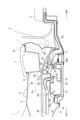
- FIG. 1 is a side cross-sectional view of a vehicle power supply system according to an embodiment of the present invention.
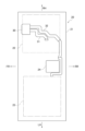
- 2 is a schematic plan view of the battery pack shown in FIG. 1.
- FIG. 3 is a schematic diagram showing the electrical connection between the battery inside the battery pack and the service disconnect switch.
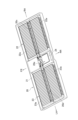
- FIG. 4 is a schematic perspective view of a battery pack.
- FIG. 5 is a schematic perspective view showing the internal structure of the battery pack.
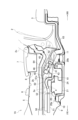
- FIG. 6 is a side sectional view of a vehicle power supply system according to another embodiment of the present invention.
- FIG. 1 indicates the front side of the vehicle
- RR indicates the rear side of the vehicle
- RH indicates the right side in the vehicle width direction
- LH indicates the left side in the vehicle width direction.
- the vehicle power supply system 1 is applied to so-called left-hand drive vehicles.
- the steering wheel (not shown) and the driver's seat are arranged in the left part of the vehicle interior, and the passenger's seat is arranged in the right part of the vehicle interior.
- the vehicle power supply system 1 can be applied to a so-called right-hand drive vehicle.
- the steering wheel (not shown) and the driver's seat are located on the right side of the vehicle interior, and the passenger's seat is located on the left side of the vehicle interior.
- a pair of left and right front seats 2 are arranged in the front part of the vehicle compartment, and rear seats 3 are arranged in the rear part of the vehicle compartment.
- the front seat 2 located at the driver's seat on the left side in the vehicle width direction and the front seat 2 located at the front passenger seat on the right side in the vehicle width direction are arranged in the front part of the vehicle interior.
- Each front seat 2 has a seat frame 2a configured to slide on seat rails 4 in the longitudinal direction of the vehicle.
- Each front seat 2 has a seat cushion 2b arranged on the seat surface portion of the seat frame 2a and a seat back 2c arranged on the backrest portion of the seat frame 2a.
- a center console 5 is arranged between the pair of left and right front seats 2 .
- a shift knob 6, an armrest 7, and the like are arranged on the upper portion of the center console 5.
- a console box 8 is accommodated inside the center console 5 .
- a battery pack 20 (high voltage battery) is arranged extending in the vehicle width direction.
- a horizontally long battery pack 20 is arranged to extend from under the front seat 2 (driver's seat) on the left side in the vehicle width direction to under the front seat 2 (passenger seat) on the right side in the vehicle width direction through the center console 5. . That is, the battery pack 20 is arranged below two front seats 2 adjacent to each other in the vehicle width direction.
- a front cross member 10 extends in front of the battery pack 20 along the vehicle width direction.
- a front coupling portion 20 a is provided at the front portion of the battery pack 20 , and the front coupling portion 20 a is coupled to the front cross member 10 .
- rear cross member 11 extends in the vehicle width direction behind battery pack 20 .
- a rear joint portion 20 b is provided at the rear portion of the battery pack 20 , and the rear joint portion 20 b is joined to the rear cross member 11 .
- a service disconnect switch (hereinafter also referred to as "SD switch") 30 is arranged below the front seat 2 (passenger seat) on the right side in the vehicle width direction. Specifically, the SD switch 30 is arranged at a position below the front seat 2 on the right side in the vehicle width direction on the upper surface of the battery pack 20 .
- the SD switch 30 is for cutting off the voltage circuit of the battery pack 20 . Manually cut off the fuse of the high voltage circuit by removing the plug inserted in the SD switch 30 as an emergency measure when the bonnet hood of the motor room with the fuse box for cutting off the high voltage power supply cannot be opened. can be done.
- the vehicle power supply system 1 may be applied to a right-hand drive vehicle, and the SD switch 30 may be arranged below the front seat 2 (passenger seat) on the left side in the vehicle width direction.
- the SD switch 30 can be arranged at a position below the front seat 2 on the left side in the vehicle width direction on the upper surface of the battery pack 20 .
- the battery pack 20 has a battery case 21.
- a first battery group 22 is arranged inside the battery case 21 at a position below the front seat 2 (passenger seat) on the right side in the vehicle width direction.
- a second battery group 23 is arranged below the front seat 2 (driver's seat) on the left side in the vehicle width direction inside the battery case 21 .
- the first battery group 22 is configured by electrically connecting a plurality of first batteries 22a.
- a plurality of substantially rectangular parallelepiped first batteries 22a are arranged vertically, and these first batteries 22a are electrically connected in series or in parallel.
- the first batteries 22a are arranged in two rows on the front side and the rear side in the longitudinal direction of the vehicle. is formed with a first flow path 20c as a flow path for cooling air.
- the second battery group 23 is configured by electrically connecting a plurality of second batteries 23a.
- a plurality of substantially rectangular parallelepiped second batteries 23a are arranged vertically, and these second batteries 23a are electrically connected in series or in parallel.
- the second batteries 23a are arranged in two rows on the front side and the rear side in the longitudinal direction of the vehicle. is formed with a second flow path 20d as a flow path for cooling air.
- first battery group 22 and the second battery group 23 inside the battery case 21 there are a downstream end of the first flow path 20c and a downstream end of the second flow path 20d.
- a collective channel 20e is formed where the ends converge.
- An internal duct 24 is provided inside the battery case 21, and the internal duct 24 defines a collective flow path 20e.
- the SD switch 30 and the first battery group 22 are electrically connected by a first bus bar 31 as a first wire (see FIG. 3). That is, the first battery group 22 arranged below the front seat 2 (passenger seat) on the right side in the vehicle width direction is connected to the SD switch 30 via the first bus bar 31 .
- an electric wire (conductor) other than a busbar may be used to connect the SD switch 30 and the first battery group 22 .
- the SD switch 30 and the second battery group 23 are electrically connected by a second bus bar 32 as a second wire (see FIG. 3). That is, the second battery group 23 arranged below the front seat 2 (driver's seat) on the left side in the vehicle width direction is connected to the SD switch 30 via the second bus bar 32 .
- wires (conductors) other than bus bars may be used to connect the SD switch 30 and the second battery group 23.
- a battery duct 25 is provided at each end of the battery pack 20 in the vehicle width direction (see FIG. 2). These battery ducts 25 have suction ports (not shown) that open downward. On the other hand, an opening 26 for discharging cooling air is provided at the center position of the upper surface of the battery pack 20 in the vehicle width direction (see FIG. 4). In some embodiments, the suction port of the battery duct 25 may open sideways or upward.
- the air outside the battery pack 20 is introduced into the battery pack 20 as cooling air.
- the cooling air is taken into the battery case 21 from the battery duct 25 on the right side in the vehicle width direction, and passes through the first flow path 20c on the right side in the vehicle width direction and the collective flow path 20e in the center in the vehicle width direction. , is discharged to the outside of the battery case 21 through the discharge opening 26 .
- the cooling air is also taken into the battery case 21 from the battery duct 25 on the left side in the vehicle width direction, passes through the second flow path 20d on the left side in the vehicle width direction, and the collective flow path 20e at the center in the vehicle width direction, and is discharged. It is discharged to the outside of the battery case 21 through the opening 26 for the battery.
- a cooling fan 40 is arranged directly above the battery pack 20 and between the pair of left and right front seats 2 .
- the cooling fan 40 includes a scroll casing 43 with a downwardly opening suction port 41 and a rearwardly opening discharge port 42 , a rotor blade 44 disposed inside the scroll casing 43 , and the rotor blades 44 . It is a centrifugal fan having a motor 45 that rotates.
- the front seat 2 and the cooling fan 40 may be arranged so as to overlap when viewed in the vehicle width direction. Thereby, the cooling fan 40 can be arranged between the pair of left and right front seats 2 .
- the entire cooling fan 40 is arranged so as to be included in the outline of the front seat 2 when viewed in the vehicle width direction. good too.
- the cooling fan 40 is arranged so that the rotating shaft 46 of the rotor blade 44 is inclined backward. “Rearward tilt” means that the upper portion of the rotating shaft 46 is tilted to be positioned on the rear side in the vehicle front-rear direction with respect to the lower portion of the rotating shaft 46 .
- the upper surface of the battery pack 20 is provided with an opening 26 for discharging cooling air, and the cooling fan 40 is arranged so that the extension of the rotating shaft 46 of the rotor blade 44 passes through the opening 26 described above.
- the cooling fan 40 may be arranged so that the entire motor 45 of the cooling fan 40 overlaps the battery pack 20 in plan view. Thereby, the cooling fan 40 can be arranged directly above the battery pack 20 .
- the cooling fan 40 may be arranged so that the extension of the rotating shaft 46 of the rotor blade 44 passes through the upper surface of the battery pack 20 in order to arrange the cooling fan 40 directly above the battery pack 20 . .
- a DC/DC converter 50 is arranged in front of the battery pack 20 .
- a holding bracket (not shown) is coupled to the upper side of battery pack 20 , and DC/DC converter 50 is held on battery pack 20 by this holding bracket.
- a substantially rectangular parallelepiped DC/DC converter 50 is placed horizontally.
- the DC/DC converter 50 arranged horizontally has a suction port 51 opened downward and a discharge port 52 opened rearward.
- the DC/DC converter 50 is a device that converts DC power into DC power, and has a function of changing voltage.
- the DC/DC converter 50 according to the present embodiment is a step-down converter, which steps down the power from the battery pack 20, which is a heavy-voltage battery, to make it weak, and supplies power to a weak-voltage battery (a so-called 12V battery).
- the DC/DC converter 50 is arranged such that the rearmost portion of the DC/DC converter 50 is located forward of the frontmost portion of the seatback 2c.
- the DC/DC converter 50 is arranged so that the foremost portion of the DC/DC converter 50 is located forward of the foremost portion of the battery pack 20 .
- the DC/DC converter 50 may be arranged such that the rearmost part of the DC/DC converter 50 is positioned forward of the frontmost part of the battery pack 20 . Thereby, the DC/DC converter 50 can be arranged in front of the battery pack 20 .
- the DC/DC converter 50 is arranged in front of the cooling fan 40 so as to be aligned with the cooling fan 40 in the longitudinal direction of the vehicle. Therefore, the DC/DC converter 50 is arranged in the area of the center console 5 (the central position in the vehicle width direction).
- the cooling fan 40 and the DC/DC converter 50 may be arranged side by side at the same height level. Thereby, the DC/DC converter 50 can be arranged so as to be aligned with the cooling fan 40 in the longitudinal direction of the vehicle.
- cooling fan 40 and DC/DC converter 50 are arranged so that cooling fan 40 and DC/DC converter 50 are at least partially overlapped when viewed in the vehicle front-rear direction, in order to arrange DC/DC converter 50 side by side with cooling fan 40 in the vehicle front-rear direction. may be placed.
- the top of the DC/DC converter 50 may be positioned lower than the top of the cooling fan 40 and the bottom of the DC/DC converter 50 may be higher than the bottom of the cooling fan 40. .
- the DC/DC converter 50 can be arranged so as to be aligned with the cooling fan 40 in the longitudinal direction of the vehicle.
- a cooling duct (first duct 61) is provided between the battery pack 20 and the cooling fan 40, and a cooling duct (second duct 62) is provided between the DC/DC converter 50 and the cooling fan 40. are placed.
- the first duct 62 is connected between the discharge opening 26 of the battery pack 20 and the suction port 41 of the cooling fan 40
- the second duct 62 is connected between the discharge port 52 of the DC/DC converter 50 and the first It is connected between the connecting port 61a of the duct 61 and the connecting port 61a.
- cooling fan 40 By driving cooling fan 40, air outside battery pack 20 is introduced into battery pack 20 as cooling air, and air outside DC/DC converter 50 is introduced into DC/DC converter 50 as cooling air. be.
- an exhaust duct 63 is connected to the outlet 42 of the cooling fan 40 .
- the exhaust duct 63 extends rearward through both sides of the trunk in the vehicle width direction, and exhausts the air from the cooling fan 40 to the outside of the vehicle.
- the vehicle power supply system 1 includes a battery pack 20 arranged below two front seats 2 adjacent in the vehicle width direction.
- the vehicle power supply system 1 is arranged above the battery pack 20 and between the two front seats 2, and is a fan (cooling fan 40) that introduces the air outside the battery pack 20 into the battery pack 20.
- a mounting space for the cooling fan 40 can be secured, and a space in front of and behind the battery pack 20 can be secured. Therefore, it is possible to arrange the cooling fan 40 so as not to protrude to the rear seat 3 side after arranging the battery pack 20 so as to be accommodated under the front seat 2 .
- the length of the cooling duct (first duct 61) connecting between the battery pack 20 and the cooling fan 40 can be shortened. Therefore, the pressure loss of the cooling air due to the length of the first duct 61 can be suppressed, and the cooling efficiency of the battery pack 20 is improved.
- the vehicle power supply system 1 includes a converter (DC/DC converter 50) arranged in front of the cooling fan 40 so as to be aligned with the cooling fan 40 in the longitudinal direction of the vehicle.
- a converter DC/DC converter 50
- the cooling duct (second duct 62) connected between the DC/DC converter 50 and the cooling fan 40 does not have a portion that bends at right angles, and the route of the second duct 62 can be arranged linearly in a plan view. Become. The cooling air pressure loss due to the shape of the second duct 62 can be suppressed, and the cooling efficiency of the DC/DC converter 50 is improved.
- the DC/DC converter 50 is arranged in front of the battery pack 20 .
- the capacity of the console box 8 must be reduced in order to secure the mounting space for the DC/DC converter 50. sometimes not.
- the console box 8 capacity can be expanded.
- the DC/DC converter 50 By arranging the DC/DC converter 50 in front of the battery pack 20 , the DC/DC converter 50 is positioned in front of the vehicle rather than the two front seats 2 . Interference between the seat frame 2a and the DC/DC converter 50 can be avoided even when the seat frame 2a of the front seat 2 intrudes toward the center in the vehicle width direction during a vehicle collision (side collision).
- the vehicle power supply system 1 includes a service disconnect switch (SD switch) 30 that is arranged below one of the two front seats 2 and cuts off the voltage circuit of the battery pack 20 . .
- SD switch service disconnect switch
- the SD switch 30 is arranged, for example, in the first battery group 22 arranged below one front seat 2 of the two front seats 2 and the second battery group 22 arranged below the other front seat 2. It is arranged in the area between group 23 (approximately at the center in the vehicle width direction). By arranging the SD switch 30 below one of the two front seats 2 (passenger seat), compared to the case where the SD switch 30 is arranged at a substantially central position in the vehicle width direction. , the SD switch 30 can be easily accessed from the outside of the vehicle.
- the vehicle power supply system 1 is arranged below one of the front seats 2 inside the battery pack 20, and is configured by electrically connecting a plurality of first batteries 22a.
- a group 22 is provided.
- the vehicle power supply system 1 includes a second battery group 23 arranged below the other front seat 2 inside the battery pack 20 and configured by electrically connecting a plurality of second batteries 23a.
- the vehicle power supply system 1 electrically connects a first wire (first bus bar 31) that electrically connects the SD switch 30 and the first battery group 22, and the SD switch 30 and the second battery group 23.
- a second electric wire (second bus bar 32) to be connected is provided.
- the SD switch 30 can be arranged at the foot of the front seat 2 (passenger seat) away from the area (center console 5) between the first battery group 22 and the second battery group 23.
- the cooling fan 40 consists of a casing (scroll casing 43) having a suction port 41 opened downward and a discharge port 42 opening rearward, and rotor blades 44 disposed inside the scroll casing 43. and have Cooling fan 40 is arranged such that rotating shaft 46 of rotor 44 is inclined rearward.
- the cooling fan 40 centrifugal fan
- the discharge port 42 of the cooling fan 40 becomes closer to the underfloor side. Therefore, the length of the exhaust duct 63 behind the cooling fan 40 can be shortened.
- a space is created between the suction port 41 of the cooling fan 40 (centrifugal fan) and the upper surface of the battery pack 20 .
- a cooling duct (second duct 62) connecting between the DC/DC converter 50 and the cooling fan 40 can be connected to this space.
- the vehicle power supply system 1 includes a battery pack 20 arranged below two front seats 2 adjacent to each other in the vehicle width direction, and a battery pack 20 arranged below one of the two front seats 2. and a service disconnect switch (SD switch) 30 arranged.
- the vehicle power supply system 1 also includes a converter (DC/DC converter 50) arranged in front of the battery pack 20 and a fan (cooling fan) arranged above the battery pack 20 and between the two front seats 2. fan 40).
- the vehicle power supply system 1 includes a cooling duct (first duct 61) connected between the battery pack 20 and the cooling fan 40, and a cooling duct (second duct 61) connected between the DC/DC converter 50 and the cooling fan 40. duct 62).
- the cooling fan 40 and the cooling ducts are connected to the battery pack. 20 can be mounted on the upper surface.
- a mounting space for the cooling fan 40 and the cooling ducts (the first duct 61 and the second duct 62) can be secured, and a space in front of and behind the battery pack 20 can be secured. Therefore, it is possible to arrange the cooling fan 40 so as not to protrude to the rear seat 3 side after arranging the battery pack 20 so as to be accommodated under the front seat 2 .
- a space is formed in the vertical direction between the console box 8 and the cooling fan 40, and the air conditioner duct 64 for the rear seat 3 is arranged in this space.
- the air conditioner duct 64 for the rear seat 3 is arranged in this space.
Landscapes
- Engineering & Computer Science (AREA)
- Chemical & Material Sciences (AREA)
- Mechanical Engineering (AREA)
- Transportation (AREA)
- Chemical Kinetics & Catalysis (AREA)
- Electrochemistry (AREA)
- General Chemical & Material Sciences (AREA)
- Power Engineering (AREA)
- Manufacturing & Machinery (AREA)
- Life Sciences & Earth Sciences (AREA)
- Sustainable Development (AREA)
- Sustainable Energy (AREA)
- Combustion & Propulsion (AREA)
- Aviation & Aerospace Engineering (AREA)
- Microelectronics & Electronic Packaging (AREA)
- Arrangement Or Mounting Of Propulsion Units For Vehicles (AREA)
Abstract
Description
2 前部座席
20 バッテリパック
22 第1バッテリグループ
22a 第1バッテリ
23 第2バッテリグループ
23a 第2バッテリ
30 SDスイッチ(サービスディスコネクトスイッチ)
31 第1バスバー(第1電線)
32 第2バスバー(第2電線)
40 冷却ファン
41 吸込口
42 吐出口
43 スクロールケーシング(ケーシング)
44 回転翼
50 DC/DCコンバータ(コンバータ)
61 第1ダクト(冷却ダクト)
62 第2ダクト(冷却ダクト)
Claims (7)
- 車幅方向に隣り合う2つの前部座席の下方に配置されるバッテリパックと、
前記バッテリパックの上方で且つ2つの前記前部座席の間に配置され、前記バッテリパックの外部の空気を前記バッテリパックの内部に導入するファンと、を備える、
車両用電源システム。 - 前記ファンと車両前後方向に並ぶように前記ファンの前方に配置されるコンバータを備える、
請求項1に記載の車両用電源システム。 - 前記コンバータは、前記バッテリパックの前方に配置される、
請求項2に記載の車両用電源システム。 - 2つの前記前部座席のうち一方の前記前部座席の下方に配置され、前記バッテリパックの電圧回路を遮断するサービスディスコネクトスイッチを備える、
請求項1から3の何れか一項に記載の車両用電源システム。 - 前記バッテリパックの内部において前記一方の前記前部座席の下方の位置に配置され、複数の第1バッテリを電気的に接続して構成される第1バッテリグループと、
前記バッテリパックの内部において他方の前記前部座席の下方の位置に配置され、複数の第2バッテリを電気的に接続して構成される第2バッテリグループと、
前記サービスディスコネクトスイッチと前記第1バッテリグループとを電気的に接続する第1電線と、
前記サービスディスコネクトスイッチと前記第2バッテリグループとを電気的に接続する第2電線と、を備える
請求項4に記載の車両用電源システム。 - 前記ファンは、吸込口が下方に向けて開口され、吐出口が後方に向けて開口されたケーシングと、前記ケーシングの内部に配置された回転翼と、を有し、
前記ファンが、前記回転翼の回転軸が後方に傾斜するように配置される、
請求項1から5の何れか一項に記載の車両用電源システム。 - 車幅方向に隣り合う2つの前部座席の下方に配置されるバッテリパックと、
2つの前記前部座席のうち一方の前記前部座席の下方に配置されるサービスディスコネクトスイッチと、
前記バッテリパックの前方に配置されるコンバータと、
前記バッテリパックの上方で且つ2つの前記前部座席の間に配置されるファンと、
前記バッテリパックと前記ファンとの間に繋がる第1ダクトと、
前記コンバータと前記ファンとの間に繋がる第2ダクトと、を備える、
車両用電源システム。
Priority Applications (5)
| Application Number | Priority Date | Filing Date | Title |
|---|---|---|---|
| PCT/JP2021/035641 WO2023053206A1 (ja) | 2021-09-28 | 2021-09-28 | 車両用電源システム |
| US18/696,103 US20250132416A1 (en) | 2021-09-28 | 2021-09-28 | Vehicle power supply system |
| CN202180102829.0A CN118043218A (zh) | 2021-09-28 | 2021-09-28 | 车辆用电源系统 |
| JP2023550791A JP7729392B2 (ja) | 2021-09-28 | 2021-09-28 | 車両用電源システム |
| EP21958598.1A EP4414206A4 (en) | 2021-09-28 | 2021-09-28 | VEHICLE ELECTRICAL POWER SYSTEM |
Applications Claiming Priority (1)
| Application Number | Priority Date | Filing Date | Title |
|---|---|---|---|
| PCT/JP2021/035641 WO2023053206A1 (ja) | 2021-09-28 | 2021-09-28 | 車両用電源システム |
Publications (1)
| Publication Number | Publication Date |
|---|---|
| WO2023053206A1 true WO2023053206A1 (ja) | 2023-04-06 |
Family
ID=85781489
Family Applications (1)
| Application Number | Title | Priority Date | Filing Date |
|---|---|---|---|
| PCT/JP2021/035641 Ceased WO2023053206A1 (ja) | 2021-09-28 | 2021-09-28 | 車両用電源システム |
Country Status (5)
| Country | Link |
|---|---|
| US (1) | US20250132416A1 (ja) |
| EP (1) | EP4414206A4 (ja) |
| JP (1) | JP7729392B2 (ja) |
| CN (1) | CN118043218A (ja) |
| WO (1) | WO2023053206A1 (ja) |
Cited By (2)
| Publication number | Priority date | Publication date | Assignee | Title |
|---|---|---|---|---|
| WO2025220167A1 (ja) * | 2024-04-17 | 2025-10-23 | 日産自動車株式会社 | 車両下部構造 |
| WO2026047826A1 (ja) * | 2024-08-26 | 2026-03-05 | 日産自動車株式会社 | バッテリを冷却するファンの排気構造 |
Citations (3)
| Publication number | Priority date | Publication date | Assignee | Title |
|---|---|---|---|---|
| JP2009255774A (ja) * | 2008-04-17 | 2009-11-05 | Toyota Motor Corp | 車両 |
| JP2011063042A (ja) | 2009-09-15 | 2011-03-31 | Suzuki Motor Corp | 車両のバッテリ冷却構造 |
| JP2012140054A (ja) * | 2010-12-28 | 2012-07-26 | Suzuki Motor Corp | 電動車両 |
Family Cites Families (3)
| Publication number | Priority date | Publication date | Assignee | Title |
|---|---|---|---|---|
| JP4363350B2 (ja) * | 2005-03-30 | 2009-11-11 | トヨタ自動車株式会社 | 二次電池の冷却構造 |
| WO2013183501A1 (ja) * | 2012-06-05 | 2013-12-12 | 日産自動車株式会社 | 電動車両の冷却風排気ダクト構造 |
| JP6476906B2 (ja) | 2015-01-23 | 2019-03-06 | スズキ株式会社 | 車両用バッテリパックの冷却構造 |
-
2021
- 2021-09-28 US US18/696,103 patent/US20250132416A1/en active Pending
- 2021-09-28 JP JP2023550791A patent/JP7729392B2/ja active Active
- 2021-09-28 WO PCT/JP2021/035641 patent/WO2023053206A1/ja not_active Ceased
- 2021-09-28 CN CN202180102829.0A patent/CN118043218A/zh active Pending
- 2021-09-28 EP EP21958598.1A patent/EP4414206A4/en not_active Withdrawn
Patent Citations (3)
| Publication number | Priority date | Publication date | Assignee | Title |
|---|---|---|---|---|
| JP2009255774A (ja) * | 2008-04-17 | 2009-11-05 | Toyota Motor Corp | 車両 |
| JP2011063042A (ja) | 2009-09-15 | 2011-03-31 | Suzuki Motor Corp | 車両のバッテリ冷却構造 |
| JP2012140054A (ja) * | 2010-12-28 | 2012-07-26 | Suzuki Motor Corp | 電動車両 |
Non-Patent Citations (1)
| Title |
|---|
| See also references of EP4414206A4 |
Cited By (2)
| Publication number | Priority date | Publication date | Assignee | Title |
|---|---|---|---|---|
| WO2025220167A1 (ja) * | 2024-04-17 | 2025-10-23 | 日産自動車株式会社 | 車両下部構造 |
| WO2026047826A1 (ja) * | 2024-08-26 | 2026-03-05 | 日産自動車株式会社 | バッテリを冷却するファンの排気構造 |
Also Published As
| Publication number | Publication date |
|---|---|
| JP7729392B2 (ja) | 2025-08-26 |
| JPWO2023053206A1 (ja) | 2023-04-06 |
| CN118043218A (zh) | 2024-05-14 |
| EP4414206A1 (en) | 2024-08-14 |
| US20250132416A1 (en) | 2025-04-24 |
| EP4414206A4 (en) | 2025-03-19 |
Similar Documents
| Publication | Publication Date | Title |
|---|---|---|
| JP4363350B2 (ja) | 二次電池の冷却構造 | |
| KR101490648B1 (ko) | 차량 부품 탑재 배열체 | |
| JP4774783B2 (ja) | 駆動用電池パック搭載構造 | |
| CN103975459B (zh) | 电动车用蓄电池组 | |
| JP5277362B1 (ja) | バッテリパックの車載構造 | |
| JP4539717B2 (ja) | 二次電池の冷却構造 | |
| CN114728622B (zh) | 车辆的驱动单元 | |
| CN102514470B (zh) | 蓄电装置 | |
| US12155277B2 (en) | Driving unit and vehicle | |
| JP6752258B2 (ja) | 車両 | |
| JP6688851B2 (ja) | 車両 | |
| JP7729392B2 (ja) | 車両用電源システム | |
| JP6647005B2 (ja) | 車両 | |
| JP6534334B2 (ja) | 車両 | |
| CN111952494B (zh) | 车辆用电池单元 | |
| WO2017094445A1 (ja) | 車両 | |
| CN107199869A (zh) | 车辆 | |
| JP5482697B2 (ja) | 車両用バッテリユニットの空調構造 | |
| CN112172492B (zh) | 车辆 | |
| JP6446351B2 (ja) | バッテリユニット | |
| US11489415B2 (en) | Drive unit | |
| CN106394215A (zh) | 车辆 | |
| JP4064804B2 (ja) | 車両用ワイヤハーネスの配索構造 | |
| US12095314B2 (en) | Driving unit | |
| CN114148416A (zh) | 被配置为便于电连接和气流的机动车辆地板总成 |
Legal Events
| Date | Code | Title | Description |
|---|---|---|---|
| 121 | Ep: the epo has been informed by wipo that ep was designated in this application |
Ref document number: 21958598 Country of ref document: EP Kind code of ref document: A1 |
|
| WWE | Wipo information: entry into national phase |
Ref document number: 2023550791 Country of ref document: JP |
|
| WWE | Wipo information: entry into national phase |
Ref document number: 18696103 Country of ref document: US |
|
| WWE | Wipo information: entry into national phase |
Ref document number: 202180102829.0 Country of ref document: CN |
|
| NENP | Non-entry into the national phase |
Ref country code: DE |
|
| ENP | Entry into the national phase |
Ref document number: 2021958598 Country of ref document: EP Effective date: 20240429 |
|
| WWP | Wipo information: published in national office |
Ref document number: 18696103 Country of ref document: US |
|
| WWW | Wipo information: withdrawn in national office |
Ref document number: 2021958598 Country of ref document: EP |