WO2023053497A1 - 軌道生成システム - Google Patents
軌道生成システム Download PDFInfo
- Publication number
- WO2023053497A1 WO2023053497A1 PCT/JP2022/010798 JP2022010798W WO2023053497A1 WO 2023053497 A1 WO2023053497 A1 WO 2023053497A1 JP 2022010798 W JP2022010798 W JP 2022010798W WO 2023053497 A1 WO2023053497 A1 WO 2023053497A1
- Authority
- WO
- WIPO (PCT)
- Prior art keywords
- omission
- target
- target trajectory
- trajectory
- correction
- Prior art date
- Legal status (The legal status is an assumption and is not a legal conclusion. Google has not performed a legal analysis and makes no representation as to the accuracy of the status listed.)
- Ceased
Links
Images

Classifications
-
- E—FIXED CONSTRUCTIONS
- E02—HYDRAULIC ENGINEERING; FOUNDATIONS; SOIL SHIFTING
- E02F—DREDGING; SOIL-SHIFTING
- E02F9/00—Component parts of dredgers or soil-shifting machines, not restricted to one of the kinds covered by groups E02F3/00 - E02F7/00
- E02F9/20—Drives; Control devices
-
- E—FIXED CONSTRUCTIONS
- E02—HYDRAULIC ENGINEERING; FOUNDATIONS; SOIL SHIFTING
- E02F—DREDGING; SOIL-SHIFTING
- E02F3/00—Dredgers; Soil-shifting machines
- E02F3/04—Dredgers; Soil-shifting machines mechanically-driven
- E02F3/28—Dredgers; Soil-shifting machines mechanically-driven with digging tools mounted on a dipper- or bucket-arm, i.e. there is either one arm or a pair of arms, e.g. dippers, buckets
- E02F3/36—Component parts
- E02F3/42—Drives for dippers, buckets, dipper-arms or bucket-arms
- E02F3/43—Control of dipper or bucket position; Control of sequence of drive operations
- E02F3/435—Control of dipper or bucket position; Control of sequence of drive operations for dipper-arms, backhoes or the like
- E02F3/437—Control of dipper or bucket position; Control of sequence of drive operations for dipper-arms, backhoes or the like providing automatic sequences of movements, e.g. linear excavation, keeping dipper angle constant
-
- E—FIXED CONSTRUCTIONS
- E02—HYDRAULIC ENGINEERING; FOUNDATIONS; SOIL SHIFTING
- E02F—DREDGING; SOIL-SHIFTING
- E02F3/00—Dredgers; Soil-shifting machines
- E02F3/04—Dredgers; Soil-shifting machines mechanically-driven
- E02F3/28—Dredgers; Soil-shifting machines mechanically-driven with digging tools mounted on a dipper- or bucket-arm, i.e. there is either one arm or a pair of arms, e.g. dippers, buckets
- E02F3/36—Component parts
- E02F3/42—Drives for dippers, buckets, dipper-arms or bucket-arms
- E02F3/43—Control of dipper or bucket position; Control of sequence of drive operations
- E02F3/435—Control of dipper or bucket position; Control of sequence of drive operations for dipper-arms, backhoes or the like
- E02F3/438—Memorising movements for repetition, e.g. play-back capability
-
- E—FIXED CONSTRUCTIONS
- E02—HYDRAULIC ENGINEERING; FOUNDATIONS; SOIL SHIFTING
- E02F—DREDGING; SOIL-SHIFTING
- E02F9/00—Component parts of dredgers or soil-shifting machines, not restricted to one of the kinds covered by groups E02F3/00 - E02F7/00
- E02F9/26—Indicating devices
- E02F9/261—Surveying the work-site to be treated
- E02F9/262—Surveying the work-site to be treated with follow-up actions to control the work tool, e.g. controller
-
- E—FIXED CONSTRUCTIONS
- E02—HYDRAULIC ENGINEERING; FOUNDATIONS; SOIL SHIFTING
- E02F—DREDGING; SOIL-SHIFTING
- E02F9/00—Component parts of dredgers or soil-shifting machines, not restricted to one of the kinds covered by groups E02F3/00 - E02F7/00
- E02F9/26—Indicating devices
- E02F9/264—Sensors and their calibration for indicating the position of the work tool
- E02F9/265—Sensors and their calibration for indicating the position of the work tool with follow-up actions (e.g. control signals sent to actuate the work tool)
Definitions
- the present invention relates to a trajectory generation system that generates a target trajectory for an attachment of a work machine.
- Patent Document 1 describes a technique for correcting the target point of the attachment of the work machine (discharge position in Patent Document 1).
- Patent Document 1 describes correcting the position of one target point in a series of operations of the attachment. However, when the target point is corrected, the document does not describe how a series of movements of the attachment other than the target point are performed. Therefore, the operation of the attachment after the correction of the target point may make workers around the working machine feel uneasy.
- An object of the present invention is to provide a trajectory generation system capable of suppressing the movement of an attachment from giving a worker a sense of uneasiness when correcting the target trajectory of the attachment. .
- a trajectory generation system used in a working machine having a machine body and an attachment.
- the attachment is attached to the machine body and performs work.
- the trajectory generation system generates a trajectory for a specific portion of the attachment.
- the trajectory generation system includes a target trajectory setting section and a target trajectory correction section.
- the target trajectory setting unit sets a target trajectory that includes a target trajectory composed of a plurality of target points and time information that is information about the time for the specific portion to move along the target points.
- the target trajectory correction unit corrects the target trajectory.
- the target trajectory correction unit specifies at least one omission target point from among the plurality of target points according to a predetermined condition, and sets two points adjacent to both sides of the omission target point as an omission start point and an omission end point. Set each as a point.
- the target trajectory correction unit sets a corrected target trajectory, which is a route from the omission start point to the omission end point, such that the specific part omits the omission target points at the plurality of target points on the target trajectory. do.
- the target trajectory correcting unit corrects the omission on the corrected target trajectory based on at least one of a moving distance and a moving time of the specific part from the omission start point to the omission end point on the target trajectory before correction. The time information of the specific part from the start point to the omission end point is set.
- FIG. 1 is a side view of a working machine or the like to which a trajectory generation system according to an embodiment of the present invention is applied.
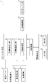
- FIG. 2 is a block diagram of a trajectory generation system according to one embodiment of the invention.
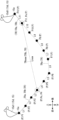
- FIG. 3 is a diagram showing a target trajectory of a specific portion of the attachment shown in FIG. 1;
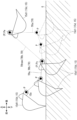
- FIG. 4 is a diagram showing a target trajectory when the bucket shown in FIG. 3 excavates.
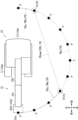
- FIG. 5 is a plan view of the work machine shown in FIG. 1, and shows a target trajectory of a specific portion of the upper swing body when the upper swing structure is swinging.
- FIG. 1 is a side view of a work machine 10 and the like to which a trajectory generation system 1 according to this embodiment is applied.
- FIG. 2 is a block diagram of the trajectory generation system 1 according to this embodiment.
- FIG. 3 is a diagram showing the target trajectory TR of the specific portion 15e of the attachment 15 shown in FIG.
- FIG. 4 is a diagram showing the target trajectory TR when the bucket 15d1 shown in FIG. 3 excavates.
- FIG. 5 is a top view of the work machine 10 shown in FIG. 1, and shows the target trajectory TR of the specific portion 15e when the upper swing body 13 is swinging.
- the trajectory generation system 1 is a system that generates the target trajectory TR (see FIG. 3) of the specific portion 15e of the attachment 15 of the working machine 10 shown in FIG.
- the trajectory generation system 1 includes an attitude sensor 21 , a situation detection section 23 (see FIG. 2), a communication device 25 , a mobile terminal 30 and a controller 40 .
- the trajectory generation system 1 may include the working machine 10 .
- the work machine 10 is a machine that performs work, such as a construction machine that performs construction work, such as a shovel. Work machine 10 is configured to be automatically operated by controller 40 .
- the work machine 10 includes a machine body 10a, an attachment 15, an actuator 17, and a drive control section 19 (see FIG. 2).
- the machine main body 10a is the main body of the work machine 10.
- the machine body 10a includes a lower traveling body 11 and an upper revolving body 13 .
- the undercarriage 11 allows the work machine 10 to travel.
- the undercarriage 11 includes, for example, crawlers.
- the upper revolving body 13 is mounted on the lower traveling body 11 so as to be revolvable about a central revolving axis extending in the vertical direction.
- the attachment 15 is a part that performs work, and is attached to the machine main body 10a (more specifically, the upper revolving body 13).
- the attachment 15 includes, for example, a boom 15b, an arm 15c, and a tip attachment 15d.
- the boom 15b is attached to the upper revolving body 13 so as to be able to rise and fall (rotatable up and down).
- Arm 15c is rotatably attached to boom 15b.
- the tip attachment 15d is provided at the tip of the attachment 15 and rotatably attached to the arm 15c.
- the tip attachment 15d may be, for example, a bucket 15d1 for excavating (scooping) soil, a device for gripping an object (such as a grapple), or a device for crushing or excavating (such as a breaker).
- a specific portion of the attachment 15 is defined as a specific portion 15e.
- the specific portion 15e is a portion that is moved along the target trajectory TR (see FIG. 3).
- the specific portion 15e is the tip of the tip attachment 15d (more specifically, the bucket 15d1) in the examples shown in FIGS. and the tip attachment 15d).
- the actuator 17 operates the working machine 10 .
- the actuator 17 includes a swing motor 17a, a boom cylinder 17b, an arm cylinder 17c, and a tip attachment cylinder 17d.
- the turning motor 17 a turns the upper turning body 13 with respect to the lower running body 11 .
- the swing motor 17a may be a hydraulic motor or an electric motor.
- the boom cylinder 17 b raises and lowers the boom 15 b with respect to the upper swing body 13 .
- the boom cylinder 17b is, for example, a hydraulic telescopic cylinder (hydraulic cylinder). The same applies to the arm cylinder 17c and the tip attachment cylinder 17d.
- the arm cylinder 17c rotates the arm 15c with respect to the boom 15b.
- the tip attachment cylinder 17d rotates the tip attachment 15d with respect to the arm 15c. If the tip attachment 15d itself is drivable, for example, as in a device for pinching an object, a cylinder or a motor for driving the tip attachment 15d may be provided.
- the drive control unit 19 controls the actuator 17.
- the drive control unit 19 may include a hydraulic circuit or an electric circuit.
- the orientation sensor 21 detects the orientation of the working machine 10 .
- the attitude sensor 21 may include a sensor (for example, a rotary encoder) that detects an angle, a sensor that detects an inclination with respect to a horizontal plane, or a sensor that detects the stroke of a hydraulic cylinder that drives the attachment 15.
- Attitude sensor 21 may detect the attitude of work machine 10 based on at least one of a two-dimensional image and a range image. In this case, the two-dimensional image or the distance image may be captured by the imaging device 23b (see FIG. 2, described later).
- the attitude sensor 21 may be mounted on the work machine 10, or may be arranged outside the work machine 10 (for example, at the work site) (the same applies to the situation detection unit 23, the communication device 25, and the controller 40).
- the posture sensor 21 includes a turning angle sensor 21a, a boom angle sensor 21b, an arm angle sensor 21c, a tip attachment angle sensor 21d, and a reference position sensor 21e.
- the turning angle sensor 21 a detects the turning angle of the upper turning body 13 with respect to the lower traveling body 11 .
- the boom angle sensor 21b detects the rotation angle of the boom 15b with respect to the upper swing body 13.
- the arm angle sensor 21c detects the rotation angle of the arm 15c with respect to the boom 15b.
- the tip attachment angle sensor 21d detects the rotation angle of the tip attachment 15d with respect to the arm 15c.
- Reference position sensor 21e detects the position and orientation of work machine 10 with respect to the work site.
- the reference position sensor 21e may perform detection using a positioning system.
- the positioning system may be a satellite positioning system, for example a global navigation satellite system (GNSS).
- GNSS global navigation satellite system
- the reference position sensor 21e may include a GNSS antenna 21e1 or the like.
- the positioning system may be one using a total station.
- the status detection unit 23 detects the status (information) of the work machine 10 (bucket 15d1).
- the situation detection unit 23 may detect the situation of the work machine 10 itself (machine situation, work situation, etc.), or may detect the situation around the work machine 10 .
- the situation detection unit 23 includes a load detection unit 23a and an imaging device 23b.
- the load detection unit 23a detects the load acting on the working machine 10 shown in FIG.
- the load detector 23 a may detect the load acting on the attachment 15 .
- the load detector 23 a may detect the load acting on the actuator 17 .
- the load detector 23 a may detect the load acting on the attachment 15 by detecting the load acting on the actuator 17 .
- the load detector 23a may detect a load acting on the tip attachment 15d (for example, the bucket 15d1).
- the load detector 23a may detect a load (eg, hydraulic pressure) acting on the tip attachment cylinder 17d (eg, bucket cylinder).
- the imaging device 23b (see FIG. 2) images the object to be imaged.
- the “object to be imaged” may be the working machine 10 or an object around the working machine 10 .
- the imaging device 23b may detect two-dimensional information (for example, position and shape) of the object to be imaged.
- the imaging device 23b may detect the three-dimensional information of the object to be imaged, and may acquire an image (distance image) having distance information (depth information).
- the imaging device 23b may detect the three-dimensional information of the object to be imaged based on the distance image and the two-dimensional image.
- the imaging device 23b may include a camera (monocular camera) that detects two-dimensional information.
- the imaging device 23b may be provided with a device that detects three-dimensional information using laser light, for example, may be provided with LIDAR (Light Detection and Ranging), for example, may be provided with a TOF (Time Of Flight) sensor. good.
- the imaging device 23b may include a device that detects three-dimensional information using radio waves (such as a millimeter wave radar, for example).
- the imaging device 23b may include a stereo camera. Specifically, for example, the imaging device 23b may detect the amount of soil in the bucket 15d1 when the tip attachment 15d is the bucket 15d1.
- the communication device 25 performs communication.
- the communication device 25 may communicate between the controller 40 and the mobile terminal 30 .
- the communication device 25 may perform communication between the controllers 40 arranged inside and outside the work machine 10 .
- Communication by the communication device 25 may include at least one of wireless communication, wired communication, and optical communication.
- the mobile terminal 30 is a device (computer) used by the worker.
- the mobile terminal 30 may be, for example, a tablet or a smartphone.
- the mobile terminal 30 includes an operation section 31 and a display section 33 .
- the operation unit 31 is operated by the operator.
- the operation unit 31 may be operated to perform settings related to automatic operation of the work machine 10 (see FIG. 1).
- the operation unit 31 may be operated to set a target trajectory TR (see FIG. 3, which will be described later) and instruct correction.
- the display unit 33 displays.
- the display unit 33 displays information about the target trajectory TR (see FIG. 3).
- the display unit 33 displays the corrected target trajectory TRb (see FIG. 3) (described later).
- the device provided with the display unit 33 for example, the mobile terminal 30
- the device provided with the operation unit 31 may be integrated or separated.
- the controller 40 is a computer that performs signal input/output, computation (processing), information storage, and the like.
- the functions of the controller 40 are realized by executing a program stored in the storage section of the controller 40 by the arithmetic section.
- the controller 40 acquires information on the orientation of the working machine 10 (see FIG. 1) detected by the orientation sensor 21 .
- the controller 40 automatically operates the work machine 10 by controlling the drive control unit 19 .
- the controller 40 sets and corrects the target trajectory TR (see FIG. 3).
- the controller 40 may be provided separately from the mobile terminal 30 or may be provided in the mobile terminal 30 .
- the controller 40 includes a target trajectory setting section 41 , a target trajectory correction section 43 and an operation control section 45 .
- the target trajectory setting unit 41 sets the target trajectory TR shown in FIG. As will be described later, the target trajectory TR may be corrected as necessary, and the target trajectory setting unit 41 (see FIG. 2) sets a pre-correction target trajectory TRa, which is the target trajectory TR before correction.
- the target trajectory TR is a target trajectory for the specific portion 15e. More specifically, an ordered set of a plurality of target points P (for example, three-dimensional coordinates) of the specific portion 15e of the attachment 15 is called a "target path". In the example shown in FIG. 3, each position and order from the target point P1 to the target point P12 correspond to the target route.
- a target trajectory TR is obtained by adding a time parameter to the target trajectory.
- this "time parameter" is, for example, the movement time (time between two points) of the specific portion 15e between two consecutive target points P.
- the time parameter is information (time information, time information) regarding the time for the specific part 15e to move along the target point P.
- the target trajectory setting unit 41 may set the pre-correction target trajectory TRa based on teaching.
- the pre-correction target trajectory TRa may be set based on the above.
- the above "teaching" is performed as follows. A worker (operator) rides the work machine 10 shown in FIG. Then, by operating the work machine 10, the operator operates the work machine 10 so as to follow the target path desired to be set as the target trajectory TR shown in FIG. Move the part 15e. Then, the target trajectory setting unit 41 (see FIG. 2) sets the trajectory along which the specific portion 15e has moved as the pre-correction target trajectory TRa.
- the pre-correction target trajectory TRa including the target trajectory and time information is stored in the controller 40 .
- the target trajectory correction unit 43 (see FIG. 2) corrects the pre-correction target trajectory TRa.
- the target trajectory correction unit 43 sets a post-correction target trajectory TRb by omitting part of the target point P from the pre-correction target trajectory TRa (details will be described later).
- the operation control unit 45 automatically operates the work machine 10 (see FIG. 1).
- the operation control unit 45 controls the work machine 10 such that the specific portion 15e of the attachment 15 moves along the target trajectory TR. More specifically, the operation control unit 45 (see FIG. 2) sets a target route (coordinates and order of each target point P) set as the target trajectory TR, and a time parameter (for example, travel time between each target point P).
- the working machine 10 (see FIG. 1) is controlled so that the specific portion 15e moves according to the following.
- the operation control unit 45 controls the operation (posture) of the work machine 10 by inputting a command signal to the drive control unit 19 (see FIG. 2).
- the target trajectory correction unit 43 shown in FIG. 2 may (automatically) correct the target trajectory TR (see FIG. 3) based on the judgment of the controller 40 .
- the target trajectory correction unit 43 may correct the target trajectory TR based on the detection result of the situation detection unit 23 input to the controller 40 . More specifically, target trajectory correction unit 43 corrects target trajectory TR (see FIG. 3) based on at least one of the situation of work machine 10 (see FIG. 1) itself and the situation around work machine 10. (Specific examples will be described later).
- the target trajectory correction unit 43 may correct the target trajectory TR when there is a command (input) other than the controller 40 .
- the target trajectory correction unit 43 may correct the target trajectory TR according to manual operation (for example, tablet operation) of the operation unit 31 by the operator.
- the outline of the correction of the target trajectory TR shown in FIG. 3 (more specifically, the pre-correction target trajectory TRa) by the target trajectory correction unit 43 is as follows.
- the target trajectory correction unit 43 will be described below with reference to FIGS. 2 and 3.
- the target trajectory correction unit 43 sets the target trajectory of the post-correction target trajectory TRb by omitting some of the plurality of target points P of the pre-correction target trajectory TRa shown in FIG. Then, the target trajectory correction unit 43 determines the time parameter of the post-correction target trajectory TRb based on the information of the pre-correction target trajectory TRa (in consideration of the pre-correction target trajectory TRa).
- the details of correction of the target trajectory TR by the target trajectory correction unit 43 are as follows.
- the target trajectory correction unit 43 sets two of the plurality of target points P on the pre-correction target trajectory TRa (two different points) as the omitted start point Ps and the omitted end point Pe.
- the order of the omission end point Pe is after the order of the omission start point Ps.
- the target trajectory correction unit 43 selects target points P (in the example shown in FIG. P10) is omitted to set the corrected target trajectory TRb. How the omission start point Ps and the omission end point Pe are determined will be described later.
- the target trajectory correction unit 43 is configured so that the operator feels the same sense of speed when the specific portion 15e moves along the pre-correction target trajectory TRa and when the specific portion 15e moves along the post-correction target trajectory TRb. , the post-correction target trajectory TRb is set. As a result, when the specific portion 15e moves according to the corrected target trajectory TRb, it is possible to prevent the operator from feeling uneasy (uncomfortable feeling). For example, a sharp movement of the attachment 15 is suppressed when the specific portion 15e moves according to the corrected target trajectory TRb.
- the target trajectory correction unit 43 calculates the omission start point Ps based on at least one of the movement distance and the movement time of the specific portion 15e from the omission start point Ps to the omission end point Pe on the pre-correction target trajectory TRa. to the omitted end point Pe is set. More specifically, the target trajectory correction unit 43 corrects the target trajectory TRb after correction from the omission start point Ps to the omission end point Pe (hereinafter referred to as the post-omission target trajectory TRnew) as in setting examples 1 and 2 below. ) is set.
- the target trajectory correction unit 43 may set the post-abbreviated target trajectory TRnew (post-correction target trajectory TRb) so that the movement time of the specific portion 15e from the abbreviated start point Ps to the abbreviated end point Pe is the same before and after the correction. good.
- the target trajectory correction unit 43 sets the post-omitting target trajectory TRnew such that the post-correction travel time Tnew described below is equal to the pre-correction travel time T.
- the corrected movement time Tnew is the movement time of the specific portion 15e from the omission start point Ps to the omission end point Pe in the corrected target trajectory TRb (that is, on the post-omission target trajectory TRnew).
- the pre-correction travel time T is the travel time of the specific portion 15e from the omission start point Ps to the omission end point Pe on the pre-correction target trajectory TRa.
- the pre-correction movement time T and the post-correction movement time Tnew are equal, the sense of speed felt by the operator when the specific portion 15e moves from the omission start point Ps to the omission end point Pe is the same before and after the correction. to some extent. Therefore, it is possible to prevent the operator from feeling anxious when he/she sees the specific portion 15e moving along the corrected target trajectory TRb.
- the target point P4 is the omission start point Ps
- the target point P11 is the omission end point Pe.
- the pre-correction movement time T is 7 seconds.
- the target trajectory correction unit 43 sets the post-omitting target trajectory TRnew such that the post-correction movement time Tnew is 7 seconds.
- the target trajectory correction unit 43 corrects the post-abbreviation target trajectory TRnew so that the average speed (average value of the magnitude of the movement speed) of the specific portion 15e from the abbreviation start point Ps to the abbreviation end point Pe is equal before and after the correction. May be set.
- the target trajectory correction unit 43 sets the post-omission target trajectory TRnew such that the following post-correction average speed Vnew is equal to the pre-correction average speed V.
- the pre-correction average speed V is the average speed of the specific portion 15e from the omission start point Ps to the omission end point Pe on the pre-correction target trajectory TRa.
- the post-correction average speed Vnew is the average speed of the specific portion 15e from the omission start point Ps to the omission end point Pe on the post-correction target trajectory TRb (that is, on the post-omission target trajectory TRnew).
- the sense of speed felt by the operator when the specific portion 15e moves from the omission start point Ps to the omission end point Pe is equal to that before and after the correction. to the same extent. Therefore, it is possible to prevent the operator from feeling anxious when he/she sees the specific portion 15e moving along the corrected target trajectory TRb.
- the time required for the specific part 15e to move from the omission start point Ps to the omission end point Pe becomes shorter after the correction than before the correction. Therefore, the attachment 15 can be efficiently moved, and the work efficiency with the attachment 15 is improved.
- the pre-correction movement time T is 7 seconds.
- the target trajectory TRb after correction by the target trajectory correction unit 43 can be set in various ways.
- the target trajectory correction unit 43 may set the post-correction target trajectory TRb based on both the pre-correction movement time T and the pre-correction average speed V.
- FIG. The target trajectory correction unit 43 calculates the target trajectory after correction based on a value obtained by performing at least one of addition, subtraction, multiplication, and division of the correction value on the pre-correction movement time T and the pre-correction average speed V.
- a trajectory TRb may be set.
- the target trajectory correction unit 43 sets the omission start point Ps and the omission end point Pe as follows, for example.
- the target trajectory correction unit 43 determines the omission start point Ps and the At least one of the omission end points Pe may be set.
- a specific example in this case is as follows.
- the target trajectory correction unit 43 may set the position of the specific portion 15e when the amount of earth in the bucket 15d1 exceeds a predetermined earth amount threshold (condition A) as the omission start point Ps.
- the target trajectory correction unit 43 may set the position of the specific portion 15e when the load acting on the bucket 15d1 exceeds a predetermined load threshold (condition B) as the omission start point Ps.
- the soil may not enter the bucket 15d1 even if the bucket 15d1 excavates, resulting in a wasteful excavation operation. Further, if the bucket 15d1 excavates too much soil, the soil may fall from the bucket 15d1, resulting in a wasteful excavation operation.
- the amount of soil in the bucket 15d1 and the load acting on the bucket 15d1 are detected by the situation detector 23 (see FIG. 2).
- the condition detection unit 23 may detect only one of the amount of soil in the bucket 15d1 and the load acting on the bucket 15d1. In the example shown in FIG. 4, the specific portion 15e is the base end portion of the bucket 15d1.
- the target trajectory correction unit 43 sets the end point of the excavation operation by the bucket 15d1 as the omission end point Pe.
- the tip of the bucket 15d1 moves downward toward the ground (below the ground surface G) and toward the upper revolving body 13 (see FIG. 1) while moving toward the arm 15c (see FIG. 1).
- the bucket 15d1 includes an operation of rotating toward the upper revolving body 13 side (excavation side).
- this excavation operation may include an operation of moving (lifting) the bucket 15d1 that has excavated the soil above the ground G in a posture (angle) capable of holding the soil.
- the end point of such a series of excavation operations of the bucket 15d1 is set as the omission end point Pe.
- the operation subsequent to the end of the excavation operation by the bucket 15d1 is, for example, an operation (lifting and turning) including turning of the upper turning body 13 (see FIG. 1).
- a point before the end point of the series of excavation operations of the bucket 15d1 may be set as the omission end point Pe.
- the target trajectory correction unit 43 determines at least one of the omission start point Ps and the omission end point Pe based on the surrounding conditions of the work machine 10 (see FIG. 1) detected by the condition detection unit 23 (see FIG. 2). May be set.
- a specific example in this case is as follows.
- ⁇ Specific example of Setting 4 Omission of turning motion>
- a part of the target point P of the pre-correction target trajectory TRa when the upper swing body 13 performs a swing motion (swing motion) with respect to the lower travel body 11 is omitted. good too.
- the target trajectory correction unit 43 omits the route of the pre-correction target trajectory TRa, and sets the post-correction target trajectory TRb so that the specific portion 15e passes through a route shorter than that before correction (does not take a detour).
- the target trajectory correction unit 43 sets the omission start point Ps and the omission end point Pe as follows.
- the attachment 15 may enter the no-entry area.
- the target trajectory correction unit 43 sets the omission start point Ps and the omission end point Pe so that the attachment 15 does not enter the entry prohibited area.
- the above-mentioned "intrusion prohibited area" is, for example, an area in which obstacles (topography, vehicles such as dump trucks, etc.) exist.
- the target trajectory correction unit 43 may set at least one of the omission start point Ps and the omission end point Pe based on information specified by the operation unit 31 (see FIG. 2). More specifically, the operator designates the target point P to be set as the omission start point Ps from among the target points P of the pre-correction target trajectory TRa using the operation unit 31 . Then, the target trajectory correction unit 43 may set the target point P designated by the operation unit 31 as the omission start point Ps. The same applies to the omission end point Pe. Furthermore, in another embodiment, the operator selects target points P (five target points P in FIG. 5) (omission target points) to be omitted from a plurality of target points P on the pre-correction target trajectory TRa. The omission start point Ps and the omission end point Pe may be set based on the omission target point.
- the display unit 33 displays information on the corrected target trajectory TRb set by the target trajectory correcting unit 43 .
- the display unit 33 may display a figure (for example, see FIGS. 3 to 5) representing the corrected target trajectory TRb.
- the display unit 33 may display a moving image showing how the attachment 15 including the specific portion 15e moves along the post-correction target trajectory TRb.
- the trajectory generation system 1 is used in a working machine 10 having a machine body 10a and an attachment 15, and includes a target trajectory setting section 41 (see FIG. 2) and a target trajectory correction section 43 (see FIG. 2). and
- the attachment 15 is attached to the machine body 10a and performs work.
- the target trajectory setting unit 41 sets the pre-correction target trajectory TRa (see FIG. 3), which is the trajectory targeted by the specific portion 15e of the attachment 15.
- the target trajectory TR includes a target route composed of a plurality of target points P and time information, which is information regarding the time for the specific portion 15e to move along the plurality of target points P.
- the target trajectory correction unit 43 (see FIG. 2) corrects the pre-correction target trajectory TRa (see FIG. 3).
- the target trajectory correction unit 43 sets two of the plurality of target points P on the pre-correction target trajectory TRa shown in FIG. 3 as the omitted start point Ps and the omitted end point Pe.
- the target trajectory correction unit 43 specifies at least one omission target point from among the plurality of target points P according to a predetermined condition, and starts omission of two points adjacent to both sides of the omission target point.
- a point Ps and an abbreviated end point Pe are set respectively. Then, the target trajectory correction unit 43 (see FIG.
- the target trajectory correction unit 43 adjusts the path from the omission start point Ps to the omission end point Pe so that the specific portion 15e omits the omission target points at a plurality of target points P on the pre-correction target trajectory TRa.
- a corrected target path is set.
- the target trajectory correction unit 43 calculates the post-correction target trajectory TRa based on at least one of the movement distance and the movement time of the specific portion 15e from the omission start point Ps to the omission end point Pe on the pre-correction target trajectory TRa.
- a time parameter (time information) of the specific portion 15e from the omission start point Ps to the omission end point Pe in TRb is set.
- a post-correction target trajectory TRb from the omission start point Ps to the omission end point Pe in consideration of at least one of the movement distance and the movement time of the specific portion 15e from the omission start point Ps to the omission end point Pe in the pre-correction target trajectory TRa (Omitted target trajectory TRnew) is set. Therefore, compared to the case where neither the moving distance nor the moving time of the specific part 15e from the omission start point Ps to the omission end point Pe in the pre-correction target trajectory TRa is considered, the following effects can be obtained.
- the post-correction target trajectory TRb can be set such that the movement of the specific portion 15e that moves along the post-correction target trajectory TRb is close to the movement of the specific portion 15e that moves along the pre-correction target trajectory TRa. Therefore, the post-correction target trajectory TRb is set so that the operator feels the same sense of speed when the specific portion 15e moves from the omission start point Ps to the omission end point Pe before and after the correction of the target trajectory TR. be able to. As a result, when the trajectory generation system 1 (see FIG. 1) corrects the target trajectory TR of the attachment 15, it is possible to prevent the operation of the attachment 15 from giving a worker around the work machine 10 a sense of uneasiness. can.
- the target trajectory correction unit 43 sets the corrected target trajectory TRb (especially the time parameter therein) shown in FIG. 3 so that the following corrected travel time Tnew is equal to the pre-correction travel time T. do.
- the corrected travel time Tnew is the travel time of the specific portion 15e (on the post-abbreviated target trajectory TRnew) from the abbreviated start point Ps to the abbreviated end point Pe on the corrected target trajectory TRb (corrected target trajectory).
- the pre-correction travel time T is the travel time of the specific portion 15e from the omission start point Ps to the omission end point Pe on the pre-correction target trajectory TRa.
- the trajectory generation system 1 shown in FIG. 1 can prevent workers around the work machine 10 from feeling uneasy.
- the target trajectory correction unit 43 sets the post-correction target trajectory TRb shown in FIG. 3 so that the following post-correction average speed Vnew is equal to the pre-correction average speed V.
- the post-correction average speed Vnew is the average speed of the specific portion 15e from the omission start point Ps to the omission end point Pe (on the omission target trajectory TRnew) on the post-correction target trajectory TRb.
- the pre-correction average speed V is the average speed of the specific portion 15e from the omission start point Ps to the omission end point Pe on the pre-correction target trajectory TRa.
- the sense of speed felt by the operator when the specific portion 15e moves from the omission start point Ps to the omission end point Pe can be made approximately the same before and after the correction of the target trajectory TR. Therefore, the trajectory generation system 1 shown in FIG. 1 can prevent workers around the work machine 10 from feeling uneasy. In this case, the movement time of the specific portion 15e from the omission start point Ps to the omission end point Pe shown in FIG. 3 can be shorter in the post-correction target trajectory TRb than in the pre-correction target trajectory TRa. Therefore, the specific portion 15e (the attachment 15) can be moved efficiently, and the working efficiency of the attachment 15 can be improved.
- the work machine 10 has a bucket 15d1 shown in FIG. 4, and the trajectory generation system 1 (see FIG. 1) includes a situation detector 23 (bucket information detector) (see FIG. 2). Bucket 15d1 constitutes attachment 15 and excavates soil.
- the status detector 23 (see FIG. 2) detects status (information) regarding the bucket 15d1.
- the target trajectory correction unit 43 sets the position of the specific portion 15e when at least one of the following [Condition A] and [Condition B] is satisfied as the omission start point Ps.
- [Condition A] The situation detection unit 23 (see FIG. 2) detects that the amount of earth in the bucket 15d1 has exceeded a predetermined earth amount threshold.
- [Condition B] The situation detection unit 23 (see FIG. 2) detects that the load acting on the bucket 15d1 has exceeded a predetermined load threshold.
- the target trajectory correction unit 43 sets the omission target points based on the position of the specific portion 15e when at least one of [Condition A] and [Condition B] is satisfied. good too.
- the above configuration can prevent the bucket 15d1 from excavating too much soil.
- the situation detection unit 23 detects only one of the soil amount in the bucket 15d1 and the load acting on the bucket 15d1, and the target trajectory correction unit 43 detects [condition A] and [condition B].
- the trajectory generation system 1 includes a display section 33 that displays information on the corrected target trajectory TRb (see FIG. 3) set by the target trajectory correction section 43.
- FIG. 3 displays information on the corrected target trajectory TRb (see FIG. 3) set by the target trajectory correction section 43.
- the display unit 33 displays the information without actually moving the specific part 15e according to the corrected target trajectory TRb shown in FIG. Information on TRb can be notified in advance.
- connection of each component shown in FIG. 2 etc. may be changed.
- values such as thresholds for example, earth volume thresholds, load thresholds
- the number of components may vary and some components may not be provided.
- the fixation, connection, etc. between components may be direct or indirect.
- what has been described as a plurality of different members or parts may be treated as one member or part.
- what has been described as one member or portion may be divided into a plurality of different members or portions.
- each component may have only a portion of each feature (function, arrangement, shape, actuation, etc.).
- the trajectory generation system includes a target trajectory setting unit that sets a target trajectory including a target trajectory composed of a plurality of target points and time information that is information about the time for the specific part to move along the target points; and a target trajectory correction unit that corrects the target trajectory.
- the target trajectory correction unit specifies at least one omission target point from among the plurality of target points according to a predetermined condition, and sets two points adjacent to both sides of the omission target point as an omission start point and an omission end point.
- the target trajectory correcting unit calculates, based on at least one of a moving distance and a moving time of the specific part from the omission start point to the omission end point on the target trajectory before correction, the The time information of the specific portion from the omission start point to the omission end point is set.
- the target trajectory correcting unit adjusts the movement time of the specific part from the omission start point to the omission end point on the corrected target trajectory from the omission start point on the target trajectory before correction to the omission time.
- the time information in the corrected target trajectory may be set so as to be equal to the movement time of the specific portion up to the end point.
- the target trajectory correction unit adjusts the average speed of the specific part from the omission start point to the omission end point on the corrected target trajectory from the omission start point to the omission end point on the target trajectory before correction.
- the post-correction target trajectory may be set so as to be equal to the average speed of the specific portion up to the omission end point.
- the work machine has a bucket for excavating soil as the attachment, and further includes a bucket information detection unit that detects information about the bucket, and the target trajectory correction unit determines whether the amount of soil in the bucket is When the bucket information detection unit detects that a predetermined soil amount threshold is exceeded, and when the bucket information detection unit detects that the load acting on the bucket exceeds the predetermined load threshold.
- the omission target point may be set based on the position of the specific part when at least one of the conditions is satisfied.
- the above configuration may further include a display section for displaying at least one of the corrected target trajectory set by the target trajectory correction section and the time information.
- the above configuration may further include a working machine having a machine body and an attachment attached to the machine body for performing work.
Landscapes
- Engineering & Computer Science (AREA)
- Mining & Mineral Resources (AREA)
- Civil Engineering (AREA)
- General Engineering & Computer Science (AREA)
- Structural Engineering (AREA)
- Mechanical Engineering (AREA)
- Life Sciences & Earth Sciences (AREA)
- General Life Sciences & Earth Sciences (AREA)
- Paleontology (AREA)
- Operation Control Of Excavators (AREA)
Abstract
Description
図2に示す目標軌道補正部43は、コントローラ40の判断に基づいて(自動的に)、目標軌道TR(図3参照)を補正してもよい。例えば、目標軌道補正部43は、コントローラ40に入力された状況検出部23の検出結果に基づいて、目標軌道TRを補正してもよい。さらに詳しくは、目標軌道補正部43は、作業機械10(図1参照)自体の状況、および作業機械10の周囲の状況の少なくともいずれかに基づいて、目標軌道TR(図3参照)を補正してもよい(具体例は後述)。目標軌道補正部43は、コントローラ40以外の指令(入力)があったときに、目標軌道TRを補正してもよい。例えば、目標軌道補正部43は、作業者による操作部31の手動操作(例えばタブレット操作)に応じて、目標軌道TRを補正してもよい。
目標軌道補正部43による、図3に示す目標軌道TR(さらに詳しくは補正前目標軌道TRa)の補正の概要は、次の通りである。以下では、目標軌道補正部43については図2、図3を参照して説明する。目標軌道補正部43は、図3に示す補正前目標軌道TRaの複数の目標点Pの一部を省略することで、補正後目標軌道TRbの目標経路を設定する。そして、目標軌道補正部43は、補正前目標軌道TRaの情報に基づいて(補正前目標軌道TRaを考慮して)、補正後目標軌道TRbの時間パラメータを決定する。目標軌道補正部43による目標軌道TRの補正の詳細は、次の通りである。
目標軌道補正部43は、補正前目標軌道TRa上の複数の目標点Pのうち2点(互いに異なる2点)を、省略開始点Psおよび省略終了点Peとして設定する。省略終了点Peの順序は、省略開始点Psの順序よりも後である。そして、目標軌道補正部43は、補正前目標軌道TRa上の複数の目標点Pから、省略開始点Psと省略終了点Peとの間の目標点P(図3に示す例では目標点P5からP10まで)を省略した補正後目標軌道TRbを設定する。なお、省略開始点Psおよび省略終了点Peがどのように決まるかについては後述する。
目標軌道補正部43は、補正前目標軌道TRaに従って特定部位15eが移動したときと、補正後目標軌道TRbに従って特定部位15eが移動したときとで、作業者が感じる速度感が同じ程度になるように、補正後目標軌道TRbを設定する。これにより、補正後目標軌道TRbに従って特定部位15eが移動したときに、作業者に不安感(違和感)を与えることが抑制される。例えば、補正後目標軌道TRbに従って特定部位15eが移動したときの、アタッチメント15の急峻な動きが抑制される。
目標軌道補正部43は、省略開始点Psから省略終了点Peまでの特定部位15eの移動時間が補正前後で等しくなるように、省略後目標軌道TRnew(補正後目標軌道TRb)を設定してもよい。この場合、目標軌道補正部43は、下記の補正後移動時間Tnewが補正前移動時間Tと等しくなるように、省略後目標軌道TRnewを設定する。補正後移動時間Tnewは、補正後目標軌道TRbにおける省略開始点Psから省略終了点Peまでの(すなわち省略後目標軌道TRnewでの)特定部位15eの移動時間である。補正前移動時間Tは、補正前目標軌道TRaにおける省略開始点Psから省略終了点Peまでの特定部位15eの移動時間である。この場合、補正前移動時間Tと補正後移動時間Tnewとが等しくなるので、省略開始点Psから省略終了点Peまで特定部位15eが移動するときに作業者が感じる速度感が、補正前後で同じ程度になる。よって、補正後目標軌道TRbに沿って移動する特定部位15eを見た作業者に不安感を与えることが抑制される。
目標軌道補正部43は、省略開始点Psから省略終了点Peまでの特定部位15eの平均速さ(移動速度の大きさの平均値)が補正前後で等しくなるように、省略後目標軌道TRnewを設定してもよい。この場合、目標軌道補正部43は、下記の補正後平均速さVnewが補正前平均速さVと等しくなるように、省略後目標軌道TRnewを設定する。補正前平均速さVは、補正前目標軌道TRaにおける省略開始点Psから省略終了点Peまでの特定部位15eの平均速さである。補正後平均速さVnewは、補正後目標軌道TRbにおける省略開始点Psから省略終了点Peまでの(すなわち省略後目標軌道TRnewでの)特定部位15eの平均速さである。この場合、補正前平均速さVと補正後平均速さVnewとが等しくなるので、省略開始点Psから省略終了点Peまで特定部位15eが移動するときに作業者が感じる速度感が、補正前後で同じ程度になる。よって、補正後目標軌道TRbに沿って移動する特定部位15eを見た作業者に不安感を与えることが抑制される。また、省略開始点Psから省略終了点Peまで特定部位15eが移動する時間が、補正前よりも補正後の方が短くなる。よって、アタッチメント15を効率良く移動させることができ、アタッチメント15による作業効率が向上する。
目標軌道補正部43は、省略開始点Psおよび省略終了点Peを例えば次のように設定する。
目標軌道補正部43は、状況検出部23(図2参照)に検出された作業機械10(図1参照)自体の状況(機械の状況、作業の状況など)に基づいて、省略開始点Psおよび省略終了点Peの少なくともいずれかを設定してもよい。この場合の具体例は、次の通りである。
例えば、図4に示すように、バケット15d1が、土を掘削する動作(掘削動作)を行うときの、補正前目標軌道TRaの目標点Pの一部が省略されてもよい。
目標軌道補正部43は、バケット15d1内の土量が所定の土量閾値を超えたとき(条件A)の特定部位15eの位置を、省略開始点Psとして設定してもよい。目標軌道補正部43は、バケット15d1に作用する負荷が所定の負荷閾値を超えたとき(条件B)の特定部位15eの位置を、省略開始点Psとして設定してもよい。上記条件Aが満たされたときの特定部位15eの位置が、省略開始点Psとして設定されることで、バケット15d1が土を掘削しすぎることが抑制され、掘削作業の効率を向上させることができる(条件Bも同様)。バケット15d1が土を掘削しすぎた場合は、バケット15d1が掘削動作をしてもバケット15d1に土が入らず、掘削動作が無駄な動きとなる場合がある。また、バケット15d1が土を掘削しすぎた場合は、バケット15d1から土が落下する結果、掘削動作が無駄な動きとなる場合がある。バケット15d1内の土量、およびバケット15d1に作用する負荷は、上記の状況検出部23(図2参照)によって検出される。状況検出部23は、バケット15d1内の土量、および、バケット15d1に作用する負荷のうち、いずれか一方のみを検出してもよい。図4に示す例では、特定部位15eは、バケット15d1の基端部である。
目標軌道補正部43は、バケット15d1による掘削動作の終了点を、省略終了点Peとして設定する。この掘削動作は、バケット15d1の先端部が地中(地面Gよりも下側)に向かって下側および上部旋回体13(図1参照)側に移動しながら、アーム15c(図1参照)に対してバケット15d1が上部旋回体13側(掘削側)に回転する動作を含む。また、この掘削動作は、土を掘削したバケット15d1が、土を保持可能な姿勢(角度)で、地面Gよりも上側に移動する(持ち上がる)動作を含んでもよい。このようなバケット15d1の一連の掘削動作の終了点が、省略終了点Peとして設定される。バケット15d1による掘削動作の終了の次の動作は、例えば、上部旋回体13(図1参照)の旋回を含む動作(持ち上げ旋回)などである。なお、バケット15d1の一連の掘削動作の終了点よりも前の点が、省略終了点Peとして設定されてもよい。
目標軌道補正部43は、状況検出部23(図2参照)によって検出された作業機械10(図1参照)の周囲の状況に基づいて、省略開始点Psおよび省略終了点Peの少なくともいずれかを設定してもよい。この場合の具体例は、次の通りである。
例えば、図5に示すように、上部旋回体13が、下部走行体11に対して旋回する動作(旋回動作)を行うときの、補正前目標軌道TRaの目標点Pの一部が省略されてもよい。目標軌道補正部43は、補正前目標軌道TRaの経路を省略し、補正前よりも短い経路を特定部位15eが通るように(遠回りしないように)、補正後目標軌道TRbを設定する。この例では、目標軌道補正部43は、省略開始点Psおよび省略終了点Peを次のように設定する。
目標軌道補正部43は、操作部31(図2参照)で指定された情報に基づいて、省略開始点Psおよび省略終了点Peの少なくともいずれかを設定してもよい。さらに詳しくは、作業者が、補正前目標軌道TRaの目標点Pの中から、省略開始点Psとして設定したい目標点Pを操作部31で指定する。そして、目標軌道補正部43は、操作部31で指定された目標点Pを省略開始点Psとして設定してもよい。省略終了点Peについても同様である。更に、他の実施形態において、作業者が、補正前目標軌道TRa上の複数の目標点Pの中から、省略したい目標点P(図5では、5つの目標点P)(省略対象点)を指定し、当該省略対象点に基づいて省略開始点Psおよび省略終了点Peを設定しても良い。
表示部33(図2参照)は、目標軌道補正部43が設定した補正後目標軌道TRbの情報を表示する。具体的には例えば、表示部33は、補正後目標軌道TRbを表す図形(例えば図3~図5参照)を表示してもよい。表示部33は、特定部位15eを含むアタッチメント15が、補正後目標軌道TRbに従って移動する様子を表す動画を表示してもよい。
上記実施形態は様々に変形されてもよい。例えば、図2などに示す各構成要素の接続は変更されてもよい。例えば、閾値(例えば、土量閾値、負荷閾値)などの値は、一定でもよく、手動操作により変えられてもよく、何らかの条件に応じて自動的に変えられてもよい。例えば、構成要素の数が変更されてもよく、構成要素の一部が設けられなくてもよい。例えば、構成要素同士の固定や連結などは、直接的でも間接的でもよい。例えば、互いに異なる複数の部材や部分として説明したものが、一つの部材や部分とされてもよい。例えば、一つの部材や部分として説明したものが、互いに異なる複数の部材や部分に分けて設けられてもよい。例えば、各構成要素は、各特徴(作用機能、配置、形状、作動など)の一部のみを有してもよい。
Claims (6)
- 機械本体と、前記機械本体に取り付けられ作業を行うアタッチメントとを有する作業機械に用いられ前記アタッチメントの特定部位の軌道を生成する軌道生成システムであって、
複数の目標点から構成される目標経路と前記特定部位が前記目標点に沿って移動する時間に関する情報である時間情報とを含む目標軌道を設定する目標軌道設定部と、
前記目標軌道を補正する目標軌道補正部と、
を備え、
前記目標軌道補正部は、
所定の条件に応じて前記複数の目標点の中から少なくとも一つの省略対象点を特定するとともに、前記省略対象点の両側に隣接する2点を省略開始点および省略終了点としてそれぞれ設定し、
前記目標軌道上の前記複数の目標点において前記特定部位が前記省略対象点を省略するように前記省略開始点から前記省略終了点に至る経路である補正目標経路を設定し、
補正前の前記目標軌道における前記省略開始点から前記省略終了点までの前記特定部位の移動距離および移動時間のうちの少なくとも一方に基づいて、前記補正目標経路における前記省略開始点から前記省略終了点までの前記特定部位の前記時間情報を設定する、
軌道生成システム。 - 請求項1に記載の軌道生成システムであって、
前記目標軌道補正部は、前記補正目標経路における前記省略開始点から前記省略終了点までの前記特定部位の移動時間が、補正前の前記目標軌道における前記省略開始点から前記省略終了点までの前記特定部位の移動時間と等しくなるように、前記補正後の前記目標軌道における前記時間情報を設定する、
軌道生成システム。 - 請求項1に記載の軌道生成システムであって、
前記目標軌道補正部は、前記補正目標経路における前記省略開始点から前記省略終了点までの前記特定部位の平均速さが、補正前の前記目標軌道における前記省略開始点から前記省略終了点までの前記特定部位の平均速さと等しくなるように、前記補正後の前記目標軌道における前記時間情報を設定する、
軌道生成システム。 - 請求項1乃至3のいずれか1項に記載の軌道生成システムであって、
前記作業機械は、前記アタッチメントとして土を掘削するバケットを有し、前記バケットに関する情報を検出するバケット情報検出部を更に備え、
前記目標軌道補正部は、前記バケット内の土量が所定の土量閾値を超えたことが前記バケット情報検出部によって検出されたこと、および、前記バケットに作用する負荷が所定の負荷閾値を超えたことが前記バケット情報検出部によって検出されたことのうちの少なくとも一方の条件が満たされたときの前記特定部位の位置に基づいて、前記省略対象点を設定する、
軌道生成システム。 - 請求項1乃至4のいずれか1項に記載の軌道生成システムであって、
前記目標軌道補正部が設定した前記補正目標経路および前記時間情報のうちの少なくとも一方の情報を表示する表示部を更に備える、
軌道生成システム。 - 請求項1乃至5のいずれか1項に記載の軌道生成システムであって、
機械本体と、前記機械本体に取り付けられ作業を行うアタッチメントとを有する作業機械を更に備える、軌道生成システム。
Priority Applications (3)
| Application Number | Priority Date | Filing Date | Title |
|---|---|---|---|
| US18/693,782 US12540451B2 (en) | 2021-09-29 | 2022-03-11 | Trajectory generation system |
| EP22875381.0A EP4386145B1 (en) | 2021-09-29 | 2022-03-11 | Trajectory generation system |
| CN202280064451.4A CN117999391A (zh) | 2021-09-29 | 2022-03-11 | 轨迹生成系统 |
Applications Claiming Priority (2)
| Application Number | Priority Date | Filing Date | Title |
|---|---|---|---|
| JP2021159775A JP7615995B2 (ja) | 2021-09-29 | 2021-09-29 | 軌道生成システム |
| JP2021-159775 | 2021-09-29 |
Publications (1)
| Publication Number | Publication Date |
|---|---|
| WO2023053497A1 true WO2023053497A1 (ja) | 2023-04-06 |
Family
ID=85782171
Family Applications (1)
| Application Number | Title | Priority Date | Filing Date |
|---|---|---|---|
| PCT/JP2022/010798 Ceased WO2023053497A1 (ja) | 2021-09-29 | 2022-03-11 | 軌道生成システム |
Country Status (5)
| Country | Link |
|---|---|
| US (1) | US12540451B2 (ja) |
| EP (1) | EP4386145B1 (ja) |
| JP (1) | JP7615995B2 (ja) |
| CN (1) | CN117999391A (ja) |
| WO (1) | WO2023053497A1 (ja) |
Cited By (1)
| Publication number | Priority date | Publication date | Assignee | Title |
|---|---|---|---|---|
| WO2025204233A1 (ja) * | 2024-03-29 | 2025-10-02 | コベルコ建機株式会社 | 施工システム |
Families Citing this family (2)
| Publication number | Priority date | Publication date | Assignee | Title |
|---|---|---|---|---|
| WO2026004257A1 (ja) * | 2024-06-27 | 2026-01-02 | 株式会社小松製作所 | 自動旋回制御システム、作業機械および作業機械の自動旋回制御方法 |
| JP2026050041A (ja) * | 2024-09-09 | 2026-03-19 | コベルコ建機株式会社 | 制御装置 |
Citations (5)
| Publication number | Priority date | Publication date | Assignee | Title |
|---|---|---|---|---|
| JPH101968A (ja) * | 1996-06-18 | 1998-01-06 | Hitachi Constr Mach Co Ltd | 油圧建設機械の自動軌跡制御装置 |
| JP2000064359A (ja) | 1998-08-24 | 2000-02-29 | Hitachi Constr Mach Co Ltd | 自動運転建設機械 |
| US6085583A (en) * | 1999-05-24 | 2000-07-11 | Carnegie Mellon University | System and method for estimating volume of material swept into the bucket of a digging machine |
| WO2018179383A1 (ja) * | 2017-03-31 | 2018-10-04 | 株式会社小松製作所 | 作業車両の制御システム、及び作業機の軌跡設定方法 |
| EP3748087A2 (en) * | 2019-05-16 | 2020-12-09 | Doosan Infracore Co., Ltd. | Method for measuring amount of soil in bucket during excavation of excavator |
Family Cites Families (4)
| Publication number | Priority date | Publication date | Assignee | Title |
|---|---|---|---|---|
| JP6564739B2 (ja) * | 2016-06-30 | 2019-08-21 | 日立建機株式会社 | 作業機械 |
| KR102659077B1 (ko) | 2018-03-27 | 2024-04-18 | 스미도모쥬기가이고교 가부시키가이샤 | 쇼벨 |
| US20240026658A1 (en) * | 2020-08-19 | 2024-01-25 | Kobelco Construction Machinery Co., Ltd. | Target path changing system for attachment |
| WO2023053584A1 (ja) * | 2021-09-29 | 2023-04-06 | コベルコ建機株式会社 | 軌道生成システムおよびこれを備えた作業機械 |
-
2021
- 2021-09-29 JP JP2021159775A patent/JP7615995B2/ja active Active
-
2022
- 2022-03-11 CN CN202280064451.4A patent/CN117999391A/zh active Pending
- 2022-03-11 WO PCT/JP2022/010798 patent/WO2023053497A1/ja not_active Ceased
- 2022-03-11 EP EP22875381.0A patent/EP4386145B1/en active Active
- 2022-03-11 US US18/693,782 patent/US12540451B2/en active Active
Patent Citations (5)
| Publication number | Priority date | Publication date | Assignee | Title |
|---|---|---|---|---|
| JPH101968A (ja) * | 1996-06-18 | 1998-01-06 | Hitachi Constr Mach Co Ltd | 油圧建設機械の自動軌跡制御装置 |
| JP2000064359A (ja) | 1998-08-24 | 2000-02-29 | Hitachi Constr Mach Co Ltd | 自動運転建設機械 |
| US6085583A (en) * | 1999-05-24 | 2000-07-11 | Carnegie Mellon University | System and method for estimating volume of material swept into the bucket of a digging machine |
| WO2018179383A1 (ja) * | 2017-03-31 | 2018-10-04 | 株式会社小松製作所 | 作業車両の制御システム、及び作業機の軌跡設定方法 |
| EP3748087A2 (en) * | 2019-05-16 | 2020-12-09 | Doosan Infracore Co., Ltd. | Method for measuring amount of soil in bucket during excavation of excavator |
Non-Patent Citations (1)
| Title |
|---|
| See also references of EP4386145A4 |
Cited By (1)
| Publication number | Priority date | Publication date | Assignee | Title |
|---|---|---|---|---|
| WO2025204233A1 (ja) * | 2024-03-29 | 2025-10-02 | コベルコ建機株式会社 | 施工システム |
Also Published As
| Publication number | Publication date |
|---|---|
| CN117999391A (zh) | 2024-05-07 |
| JP2023049804A (ja) | 2023-04-10 |
| EP4386145A1 (en) | 2024-06-19 |
| JP7615995B2 (ja) | 2025-01-17 |
| US20240384500A1 (en) | 2024-11-21 |
| US12540451B2 (en) | 2026-02-03 |
| EP4386145A4 (en) | 2025-03-12 |
| EP4386145B1 (en) | 2026-03-11 |
Similar Documents
| Publication | Publication Date | Title |
|---|---|---|
| WO2023053497A1 (ja) | 軌道生成システム | |
| US10196796B2 (en) | Construction machine control system, construction machine, and construction machine control method | |
| CA3029812C (en) | Image display system of work machine, remote operation system of work machine, work machine, and method for displaying image of work machine | |
| EP3638857B1 (en) | A working machine provided with an image projection arrangement | |
| KR20210021945A (ko) | 굴삭기, 정보처리장치 | |
| KR20220086671A (ko) | 작업 기계의 제어 시스템, 작업 기계, 작업 기계의 제어 방법 | |
| EP3719212A1 (en) | System for remapping a control signal for excavator arm movement to a rotatory degree of freedom of a tool | |
| WO2023149309A1 (ja) | 作業機械のための自動運転システム、作業機械、および自動運転プログラム | |
| KR20220086672A (ko) | 작업 기계의 제어 시스템, 작업 기계, 및 작업 기계의 제어 방법 | |
| US20240392532A1 (en) | Trajectory-generating system and work machine comprising same | |
| JP7811484B2 (ja) | 表示制御装置、及び遠隔操作装置 | |
| EP4711531A1 (en) | System, program and method for setting target path | |
| JP2023150952A (ja) | 作業機械 | |
| JP2023050081A (ja) | 軌道生成システム | |
| WO2023149307A1 (ja) | 作業機械のための自動運転システム、作業機械、および自動運転プログラム | |
| JP2025038550A (ja) | 作業システム | |
| KR20230156220A (ko) | 건설 기계의 avm 시스템 및 이를 이용한 av 영상 생성 방법 | |
| JP2021067174A (ja) | ショベル、ショベルのシステム | |
| JP2017172207A (ja) | ショベル | |
| JP2020204265A (ja) | 油圧ショベル | |
| CN117980567A (zh) | 轨迹生成系统及具备该轨迹生成系统的工程机械 | |
| WO2025204233A1 (ja) | 施工システム | |
| JP2026072027A (ja) | 作業機械の遠隔制御システム | |
| JP2025153191A (ja) | 自動運転制御システム | |
| JP2024161795A (ja) | 掘削作業完了判定システム |
Legal Events
| Date | Code | Title | Description |
|---|---|---|---|
| 121 | Ep: the epo has been informed by wipo that ep was designated in this application |
Ref document number: 22875381 Country of ref document: EP Kind code of ref document: A1 |
|
| WWE | Wipo information: entry into national phase |
Ref document number: 2022875381 Country of ref document: EP |
|
| WWE | Wipo information: entry into national phase |
Ref document number: 18693782 Country of ref document: US |
|
| WWE | Wipo information: entry into national phase |
Ref document number: 202280064451.4 Country of ref document: CN |
|
| ENP | Entry into the national phase |
Ref document number: 2022875381 Country of ref document: EP Effective date: 20240313 |
|
| NENP | Non-entry into the national phase |
Ref country code: DE |
|
| WWG | Wipo information: grant in national office |
Ref document number: 18693782 Country of ref document: US |
|
| WWG | Wipo information: grant in national office |
Ref document number: 2022875381 Country of ref document: EP |