WO2023053546A1 - 水素製造システムおよび水素製造方法 - Google Patents
水素製造システムおよび水素製造方法 Download PDFInfo
- Publication number
- WO2023053546A1 WO2023053546A1 PCT/JP2022/017840 JP2022017840W WO2023053546A1 WO 2023053546 A1 WO2023053546 A1 WO 2023053546A1 JP 2022017840 W JP2022017840 W JP 2022017840W WO 2023053546 A1 WO2023053546 A1 WO 2023053546A1
- Authority
- WO
- WIPO (PCT)
- Prior art keywords
- steam
- hydrogen
- heat exchanger
- electrode layer
- oxygen
- Prior art date
- Legal status (The legal status is an assumption and is not a legal conclusion. Google has not performed a legal analysis and makes no representation as to the accuracy of the status listed.)
- Ceased
Links
Images

Classifications
-
- C—CHEMISTRY; METALLURGY
- C25—ELECTROLYTIC OR ELECTROPHORETIC PROCESSES; APPARATUS THEREFOR
- C25B—ELECTROLYTIC OR ELECTROPHORETIC PROCESSES FOR THE PRODUCTION OF COMPOUNDS OR NON-METALS; APPARATUS THEREFOR
- C25B1/00—Electrolytic production of inorganic compounds or non-metals
- C25B1/01—Products
- C25B1/02—Hydrogen or oxygen
- C25B1/04—Hydrogen or oxygen by electrolysis of water
- C25B1/042—Hydrogen or oxygen by electrolysis of water by electrolysis of steam
-
- C—CHEMISTRY; METALLURGY
- C25—ELECTROLYTIC OR ELECTROPHORETIC PROCESSES; APPARATUS THEREFOR
- C25B—ELECTROLYTIC OR ELECTROPHORETIC PROCESSES FOR THE PRODUCTION OF COMPOUNDS OR NON-METALS; APPARATUS THEREFOR
- C25B11/00—Electrodes; Manufacture thereof not otherwise provided for
- C25B11/02—Electrodes; Manufacture thereof not otherwise provided for characterised by shape or form
-
- C—CHEMISTRY; METALLURGY
- C25—ELECTROLYTIC OR ELECTROPHORETIC PROCESSES; APPARATUS THEREFOR
- C25B—ELECTROLYTIC OR ELECTROPHORETIC PROCESSES FOR THE PRODUCTION OF COMPOUNDS OR NON-METALS; APPARATUS THEREFOR
- C25B15/00—Operating or servicing cells
- C25B15/02—Process control or regulation
- C25B15/021—Process control or regulation of heating or cooling
-
- C—CHEMISTRY; METALLURGY
- C25—ELECTROLYTIC OR ELECTROPHORETIC PROCESSES; APPARATUS THEREFOR
- C25B—ELECTROLYTIC OR ELECTROPHORETIC PROCESSES FOR THE PRODUCTION OF COMPOUNDS OR NON-METALS; APPARATUS THEREFOR
- C25B15/00—Operating or servicing cells
- C25B15/02—Process control or regulation
- C25B15/023—Measuring, analysing or testing during electrolytic production
- C25B15/025—Measuring, analysing or testing during electrolytic production of electrolyte parameters
- C25B15/027—Temperature
-
- C—CHEMISTRY; METALLURGY
- C25—ELECTROLYTIC OR ELECTROPHORETIC PROCESSES; APPARATUS THEREFOR
- C25B—ELECTROLYTIC OR ELECTROPHORETIC PROCESSES FOR THE PRODUCTION OF COMPOUNDS OR NON-METALS; APPARATUS THEREFOR
- C25B15/00—Operating or servicing cells
- C25B15/08—Supplying or removing reactants or electrolytes; Regeneration of electrolytes
-
- C—CHEMISTRY; METALLURGY
- C25—ELECTROLYTIC OR ELECTROPHORETIC PROCESSES; APPARATUS THEREFOR
- C25B—ELECTROLYTIC OR ELECTROPHORETIC PROCESSES FOR THE PRODUCTION OF COMPOUNDS OR NON-METALS; APPARATUS THEREFOR
- C25B9/00—Cells or assemblies of cells; Constructional parts of cells; Assemblies of constructional parts, e.g. electrode-diaphragm assemblies; Process-related cell features
- C25B9/17—Cells comprising dimensionally-stable non-movable electrodes; Assemblies of constructional parts thereof
- C25B9/19—Cells comprising dimensionally-stable non-movable electrodes; Assemblies of constructional parts thereof with diaphragms
- C25B9/21—Cells comprising dimensionally-stable non-movable electrodes; Assemblies of constructional parts thereof with diaphragms two or more diaphragms
-
- C—CHEMISTRY; METALLURGY
- C25—ELECTROLYTIC OR ELECTROPHORETIC PROCESSES; APPARATUS THEREFOR
- C25B—ELECTROLYTIC OR ELECTROPHORETIC PROCESSES FOR THE PRODUCTION OF COMPOUNDS OR NON-METALS; APPARATUS THEREFOR
- C25B9/00—Cells or assemblies of cells; Constructional parts of cells; Assemblies of constructional parts, e.g. electrode-diaphragm assemblies; Process-related cell features
- C25B9/60—Constructional parts of cells
- C25B9/67—Heating or cooling means
-
- Y—GENERAL TAGGING OF NEW TECHNOLOGICAL DEVELOPMENTS; GENERAL TAGGING OF CROSS-SECTIONAL TECHNOLOGIES SPANNING OVER SEVERAL SECTIONS OF THE IPC; TECHNICAL SUBJECTS COVERED BY FORMER USPC CROSS-REFERENCE ART COLLECTIONS [XRACs] AND DIGESTS
- Y02—TECHNOLOGIES OR APPLICATIONS FOR MITIGATION OR ADAPTATION AGAINST CLIMATE CHANGE
- Y02E—REDUCTION OF GREENHOUSE GAS [GHG] EMISSIONS, RELATED TO ENERGY GENERATION, TRANSMISSION OR DISTRIBUTION
- Y02E60/00—Enabling technologies; Technologies with a potential or indirect contribution to GHG emissions mitigation
- Y02E60/30—Hydrogen technology
- Y02E60/36—Hydrogen production from non-carbon containing sources, e.g. by water electrolysis
Definitions
- the present disclosure relates to a hydrogen production system and a hydrogen production method.
- the electrolysis method has the advantage that raw materials are inexpensive and carbon dioxide (CO 2 ) is not generated in the hydrogen production process.
- CO 2 carbon dioxide
- the electrolysis method since the electrolysis method generates hydrogen by electrolysis, there is a problem that the cost of electric energy is high. Therefore, a high-temperature steam electrolysis method is conceivable in which the electric energy required for electrolysis is reduced by electrolyzing high-temperature steam at 700° C. or higher.
- a hydrogen production device that uses high-temperature steam electrolysis can reduce the electrical energy required to electrolyze water by using high-temperature steam.
- the conventional hydrogen production apparatus uses electrical energy to generate the high-temperature steam at a temperature corresponding to the operating temperature of the electrolysis of water, and the endothermic reaction of the electrolysis of water is also performed by electrical energy. ing. That is, the conventional hydrogen production apparatus operates at the thermal neutral point potential where the heat absorption of the water electrolysis and the heat generation of the water electrolysis cell are balanced, or at the potential higher than the thermal neutral point potential, and consumes a lot of electric energy. .
- Most of the cost of hydrogen production by high-temperature steam electrolysis is electricity, and if most of this electricity can be covered by renewable energy, carbon dioxide can be reduced. However, it is difficult to apply renewable energy to large-scale and stable hydrogen production because the power supply is unstable.
- the electrical energy generated by the thermal power generation system is accompanied by the generation of carbon dioxide.
- the present disclosure aims to solve the above-described problems, and aims to provide a hydrogen production system and a hydrogen production method that reduce energy costs and suppress the generation of carbon dioxide.
- the hydrogen production system of the present disclosure for achieving the above object comprises a heat exchanger that heats steam using a heat medium heated by thermal energy of 600 ° C. or higher, and a high temperature that produces hydrogen using the steam.
- the hydrogen production method of the present disclosure includes the steps of generating thermal energy of 600 ° C. or higher, heating steam using a heat medium heated by the thermal energy, and high-temperature steam electrolysis using the steam. It has a step of heating the device and a step of producing hydrogen by the high-temperature steam electrolysis device using the steam.
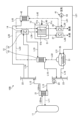
- FIG. 1 is a schematic diagram showing the hydrogen production system of the first embodiment.
- FIG. 2 is a schematic diagram representing a high temperature steam electrolysis cell.
- FIG. 3 is a graph showing the relationship between current density and thermal energy.
- FIG. 4 is a schematic diagram showing the flow of steam to a high-temperature steam electrolysis cell in the hydrogen production system of the second embodiment.
- FIG. 5 is a schematic diagram representing a hydrogen ejector.
- FIG. 6 is a schematic diagram showing the hydrogen production system of the third embodiment.
- FIG. 1 is a schematic diagram showing the hydrogen production system of the first embodiment.
- the hydrogen production system 10 includes a heat source 11, an intermediate heat exchanger (heat exchanger) 12, a solid electrolyte type high temperature steam electrolyzer (SOEC) 13, a heating a device 14;
- heat exchanger intermediate heat exchanger
- SOEC solid electrolyte type high temperature steam electrolyzer
- the heat source 11 is a high-temperature gas furnace, capable of generating thermal energy of 900°C or higher. Note that the heat source 11 is not limited to the high-temperature gas reactor, and may be anything that can generate thermal energy of 600° C. or higher. As the heat source, for example, an electric furnace, a heliostat-type solar heat collector, a boiler, boiler exhaust heat, gas turbine exhaust heat, and the like may be applied.
- the high-temperature gas-cooled reactor as the heat source 11 is a nuclear reactor that uses ceramic materials for the fuel coating, helium as the coolant, and graphite as the moderator.
- a high-temperature gas-cooled reactor can generate helium gas as a heat medium at 900° C. or higher.
- a high temperature gas reactor as the heat source 11 is connected to a circulation path L11.
- the intermediate heat exchanger 21 is connected to the circulation path L11 in addition to the heat source 11 .
- the intermediate heat exchanger 21 is connected to one end of the supply path L12 and one end of the return path L13.
- the intermediate heat exchanger 21 exchanges heat between the primary helium (primary heat medium) flowing through the circulation path L11 and the secondary helium (secondary heat medium) flowing through the supply path L12 and the return path L13. That is, the intermediate heat exchanger 21 heats the secondary helium flowing through the supply path L12 and the return path L13 to, for example, 900.degree.
- the supply header 22 is connected to the other end of the supply path L12.
- a return header 23 is connected to the other end of the return path L13.
- a circulation machine 24 is provided on the return path L13.
- the hydrogen production system 10 produces hydrogen using secondary helium as a heat medium heated with thermal energy of 900° C. or more generated by a heat source 11 .
- the high-temperature steam electrolysis device 13 uses a high-temperature steam electrolysis cell 51 as a solid electrolyte type electrolysis cell, and produces hydrogen by water electrolysis at a high temperature of about 700°C to 900°C.
- the high-temperature steam electrolyzer 13 has an electrolyte layer 51a, a porous hydrogen electrode layer 51b, and a porous oxygen electrode layer 51c.
- the high-temperature steam electrolysis cell 51 has a flat plate shape.
- the electrolyte layer 51a is a plate-shaped electrolyte membrane made of a solid electrolyte of an oxygen ion conductor.
- the electrolyte layer 51a has a porous hydrogen electrode layer 51b arranged on one side thereof and a porous oxygen electrode layer 51c arranged on the other side thereof.
- the porous hydrogen electrode layer 51b has a flat plate shape and is a cathode electrode on the hydrogen side.
- the porous oxygen electrode layer 51c has a flat plate shape and is an anode electrode on the oxygen side.
- the steam generator 31 heats water with the thermal energy of secondary helium to generate steam.
- the steam generator 31 is connected to the water supply path L31 and to one end of the first steam supply path L32.
- the intermediate heat exchanger 12 has a first heat exchanger 32 and a second heat exchanger 33 .
- the second heat exchanger 33 has a hydrogen side heat exchanger 34 and an oxygen side heat exchanger 35 .
- the first heat exchanger 32 is connected to the other end of the first steam supply path L32 and to one end of the second steam supply path L33.
- the second steam supply path L33 is connected to the steam header 36 at the other end.
- the steam header 36 is connected to one ends of the third steam supply path L34 and the fourth steam supply path L35.
- the hydrogen-side heat exchanger 34 is connected to the other end of the third steam supply path L34 and to one end of the hydrogen-side steam supply path L36.
- the oxygen-side heat exchanger 35 is connected to the other end of the fourth steam supply path L35 and to one end of the oxygen-side steam supply path L37.
- the first heat exchanger 32 superheats steam with the thermal energy of the secondary helium to generate superheated steam.
- the hydrogen-side heat exchanger 34 in the second heat exchanger 33 further superheats the superheated steam with the thermal energy of the secondary helium.
- the oxygen-side heat exchanger 35 in the second heat exchanger 33 further superheats the superheated steam with the thermal energy of the secondary helium.
- the first heat exchanger 32 is arranged on the upstream side in the steam flow direction
- the steam header 36 is arranged on the downstream side of the first heat exchanger 32
- the steam header 36 is placed on the downstream side.
- the second heat exchanger 33 is arranged.
- the hydrogen side heat exchanger 34 and the oxygen side heat exchanger 35 as the second heat exchanger 33 are arranged in parallel downstream of the steam supply path L33.
- the high-temperature steam electrolysis cell 51 is connected to the other ends of the hydrogen-side steam supply path L36 and the oxygen-side steam supply path L37.
- the hydrogen-side steam supply path L36 is connected to the inlet side of the porous hydrogen electrode layer 51b
- the oxygen-side steam supply path L37 is connected to the inlet side of the porous oxygen electrode layer 51c.
- the high-temperature steam electrolyzer 13 is connected to a hydrogen gas discharge path L38 and an oxygen gas discharge path L39.
- the high-temperature steam electrolyzer 13 is connected to a hydrogen gas discharge path L38 on the exit side of the porous hydrogen electrode layer 51b, and connected to an oxygen gas discharge path L39 on the exit side of the porous oxygen electrode layer 51c.
- the hydrogen gas discharge route L38 and the oxygen gas discharge route L39 are provided with heat recovery devices 37 and 38, respectively.
- the heat recovery devices 37 and 38 recover the heat of the generated hydrogen and oxygen, and heat the steam flowing through the first steam supply path L32, for example.
- the high-temperature steam electrolysis device 13 is connected to a power supply path L40, and can be supplied with power (electrical energy) from the outside.
- the high-temperature steam electrolyzer 13 uses steam heated by the thermal energy of secondary helium, and also uses electrical energy supplied from the power supply path L40 to produce hydrogen.
- the heating device 14 heats the high-temperature steam electrolysis cell 51 of the high-temperature steam electrolysis device 13 using the steam heated by the thermal energy of the secondary helium. In this case, the heating device 14 compensates for the heat energy lost due to the endothermic reaction when the high-temperature steam electrolysis device 13 produces hydrogen.
- the supply header 22 is connected to the second heat exchanger 33 by the heat medium supply path L14.
- the downstream end of the heat medium supply path L14 branches into two, one of which is connected to the hydrogen-side heat exchanger 34 and the other of which is connected to the oxygen-side heat exchanger 35 .
- the second heat exchanger 33 is connected to the steam generator 31 by a heat medium supply path L15.
- the upstream end of the heat medium supply path L15 branches into two, one of which is connected to the hydrogen-side heat exchanger 34 and the other of which is connected to the oxygen-side heat exchanger 35 .
- the steam generator 31 is connected to the return header 23 by a heat medium supply path L16.
- the secondary helium of the supply header 22 is supplied to the second heat exchanger 33 (the hydrogen side heat exchanger 34, the oxygen side heat exchanger 35) through the heat medium supply path L14 to superheat the steam, and the second heat Water is supplied from the exchanger 33 to the steam generator 31 through the heat medium supply path L15 to heat the water, and is returned from the steam generator 31 to the return header 23 through the heat medium supply path L16.
- the supply header 22 is connected to the first heat exchanger 32 by the heat medium supply path L17.
- the first heat exchanger 32 is connected to the return header 23 by a heat medium supply path L18. That is, the secondary helium of the supply header 22 is supplied to the first heat exchanger 32 through the heat medium supply path L17 to superheat the steam.
- the heating device 14 is provided as an intermediate heat exchanger 12 that heats steam.
- the heating device 14 is particularly composed of a hydrogen-side heat exchanger 34 as a second heat exchanger 33 and an oxygen-side heat exchanger 35 .
- the heating device 14 converts superheated steam superheated by the second heat exchanger 33 (hydrogen side heat exchanger 34, oxygen side heat exchanger) into a high-temperature steam electrolysis cell 51 (porous hydrogen electrode layer 51b, porous oxygen electrode layer). 51 c) to heat the high-temperature steam electrolysis cell 51 .
- high-temperature steam electrolysis cell 51 high-temperature superheated steam is supplied to the porous hydrogen electrode layer 51b from the hydrogen-side steam supply path L36.
- the high-temperature steam electrolysis cell 51 is supplied with power from the power supply path L40, and voltage is applied to the porous hydrogen electrode layer 51b and the porous oxygen electrode layer 51c.
- voltage By applying voltage, water vapor is electrolyzed in the porous hydrogen electrode layer 51b to generate hydrogen.
- the generated hydrogen is discharged to the hydrogen gas discharge path L38.
- oxygen ions generated by electrolysis in the porous hydrogen electrode layer 51b permeate the electrolyte layer 51a, generate oxygen in the porous oxygen electrode layer 51c, and the generated oxygen is discharged to the oxygen gas discharge path L39. be.
- the high-temperature steam electrolysis device 13 generates hydrogen and oxygen based on the electrolysis reaction according to the following formula. H2O ⁇ H2 +1/ 2O2
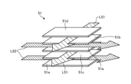
- FIG. 2 is a schematic diagram representing a high temperature steam electrolysis cell.
- the high-temperature steam electrolysis cell 51 is a plate-shaped solid electrolyte type steam electrolysis device.
- a flat plate-shaped porous hydrogen electrode layer 51b is arranged on one side of a flat plate-shaped electrolyte layer 51a, and a flat plate-shaped porous oxygen electrode layer 51c is arranged on the other side.
- a hydrogen-side separator 51d is arranged outside the porous hydrogen electrode layer 51b, and an oxygen-side separator 51e is arranged outside the porous oxygen electrode layer 51c.
- the high-temperature steam electrolysis cell 51 is internally provided with a first flow path L51 and a second flow path L52.
- the first flow path L51 is provided between the hydrogen-side separator 51d and the porous hydrogen electrode layer 51b and between the electrolyte layer 51a and the porous oxygen electrode layer 51c.
- the second flow path L52 is provided between the porous hydrogen electrode layer 51b and the electrolyte layer 51a and between the porous oxygen electrode layer 51c and the oxygen side separator 51e.
- the first flow path L51 and the second flow path L52 intersect in the orthogonal direction, but may be parallel.
- the first flow path L51 is connected to the hydrogen-side steam supply path L36 on the upstream side, and is connected to the hydrogen gas discharge path L38 on the downstream side.
- the second flow path L52 is connected upstream to the oxygen-side steam supply path L37 and downstream to the oxygen gas discharge path L39.
- the superheated steam superheated by the hydrogen side heat exchanger 34 is supplied from the hydrogen side steam supply path L36 to the first flow path L51, and the superheated steam superheated by the oxygen side heat exchanger 35 is supplied to the oxygen side steam supply. It is supplied from the path L37 to the second flow path L52.
- the heating device 14 heats the high-temperature steam electrolysis cell 51 with the supplied superheated steam.
- the superheated steam supplied to the first flow path L51 is electrolyzed to generate hydrogen and oxygen.
- the superheated steam containing hydrogen is discharged to the hydrogen gas discharge path L38.
- the steam containing oxygen is pushed out by the superheated steam supplied to the second flow path L52 and discharged to the oxygen gas discharge path L39.
- the hydrogen production method of the present embodiment includes the steps of generating thermal energy of 600° C. or higher, heating steam using secondary helium (heat medium) heated by the thermal energy, and heating the steam to a high temperature using the steam. It has a step of heating the steam electrolysis device 13 and a step of producing hydrogen by the high-temperature steam electrolysis device using steam.
- the high-temperature gas reactor as the heat source 11 generates, for example, primary helium at 950°C.
- the high-temperature primary helium flows through the circulation path L11, exchanges with the secondary helium flowing through the return path L13 in the intermediate heat exchanger 21, and heats the secondary helium to, for example, 900.degree.
- the secondary helium heat-exchanged in the intermediate heat exchanger 21 flows through the supply path L12 and is supplied to the supply header 22 at, for example, about 900.degree.
- the secondary helium in the supply header 22 is supplied to the second heat exchanger 33 through the heat medium supply path L14 to superheat steam, and is supplied from the second heat exchanger 33 to the steam generator 31 through the heat medium supply path L15. , heat the water supplied from the water supply path L31 to generate steam. Further, the secondary helium of the supply header 22 is supplied to the first heat exchanger 32 through the heat medium supply path L17 to superheat the steam.
- the steam generator 31 heats the water supplied from the water supply path L31 to generate steam.
- the steam is supplied to the first heat exchanger 32 through the first steam supply path L32, is superheated, and is supplied to the steam header 36 through the second steam supply path L33.
- the heated steam in the steam header 36 is supplied to the hydrogen-side heat exchanger 34 through the third steam supply path L34 and further superheated, for example, as high-temperature steam of 850° C. to the porous hydrogen electrode layer 51b of the high-temperature steam electrolysis cell 51. supplied.
- the heated steam in the steam header 36 is supplied to the oxygen-side heat exchanger 35 through the fourth steam supply path L35 and further superheated, for example, as high-temperature steam of 850° C. to the porous oxygen electrode layer of the high-temperature steam electrolysis cell 51. 51c.
- the high-temperature steam electrolysis cell 51 is heated by the high-temperature steam supplied from the hydrogen-side heat exchanger 34 and the oxygen-side heat exchanger 35, electrolyzes the high-temperature steam with electric power supplied from the power supply path L40, and produces hydrogen and oxygen. to generate
- high-temperature steam is supplied to the first flow path L51 of the high-temperature steam electrolysis cell 51 through the hydrogen-side steam supply path L36.
- the high-temperature steam electrolysis cell 51 is supplied with power from the power supply path L40, and voltage is applied to the porous hydrogen electrode layer 51b and the porous oxygen electrode layer 51c.
- the water vapor in the first flow path L51 is electrolyzed in the porous hydrogen electrode layer 51b to generate hydrogen, which flows downward through the first flow path L51.
- oxygen ions generated by electrolysis in the porous hydrogen electrode layer 51b permeate the high-temperature steam electrolysis cell 51 while diffusing, and are discharged as oxygen to the second flow path L2.
- the hydrogen that has flowed through the first flow path L51 is discharged to the hydrogen gas discharge path L38.
- the oxygen discharged to the second flow path L52 is discharged to the oxygen gas discharge path L39.
- the high-temperature steam is supplied to the second flow path L52 of the high-temperature steam electrolysis cell 51 through the oxygen-side steam supply path L37.
- the oxygen discharged to the second flow path L52 is pushed out to the oxygen gas discharge path L39 by the water vapor supplied to the second flow path L52.
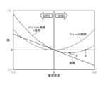
- FIG. 3 is a graph showing the relationship between current density and thermal energy.
- FIG. 3 shows the relationship between current density and thermal energy in a fuel cell (SOFC) and a high-temperature steam electrolyzer (SOEC).
- SOFC fuel cell
- SOEC high-temperature steam electrolyzer
- the conventional hydrogen production system does not have the heat source (high-temperature gas reactor) 11 as in the first embodiment, the endothermic reaction when water is electrolyzed is supplemented by the heat generated by the Joule heat generated in the high-temperature steam electrolyzer. there is That is, the conventional high-temperature steam electrolyzer operates at a potential equal to or higher than the thermal neutral point A.
- the hydrogen production system 10 of the first embodiment has a heat source (high-temperature gas reactor) 11, the high-temperature helium heated by the thermal energy of 600° C. or higher generated in the heat source 11 is used to generate steam and high-temperature steam electrolysis.
- the hydrogen production system 10 of the first embodiment can be operated at the potential of the operating point B, which is equal to or lower than the thermal neutral point A.
- the electrical energy used for water electrolysis can be reduced without converting the electrical energy into thermal energy (Joule heating).
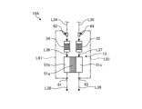
- FIG. 4 is a schematic diagram showing the flow of steam to a high-temperature steam electrolysis cell in the hydrogen production system of the second embodiment
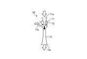
- FIG. 5 is a schematic diagram showing a hydrogen ejector.
- the basic configuration of the second embodiment is the same as that of the above-described first embodiment, and will be described with reference to FIG. Reference numerals are attached and detailed description is omitted.
- a hydrogen production system 10A (FIG. 4) includes a heat source 11, an intermediate heat exchanger 12, and a high-temperature steam electrolysis device 13, as in the first embodiment. and a heating device 14 .
- 10 A of hydrogen production systems of 2nd Embodiment change the supply structure of the steam
- the hydrogen-side heat exchanger 34 has an inlet side connected to the third steam supply path L34, and an outlet side connected to the porous hydrogen electrode layer 51b of the high-temperature steam electrolysis cell 51 by the hydrogen-side steam supply path L36.
- the oxygen side heat exchanger 35 is connected to the fourth steam supply path L35 on the inlet side, and is connected to the porous oxygen electrode layer 51c of the high-temperature steam electrolysis cell 51 by the oxygen side steam supply path L37 on the outlet side.
- the hydrogen gas discharge path L38 is connected to the porous hydrogen electrode layer 51b
- the oxygen gas discharge path L39 is connected to the porous oxygen electrode layer 51c.
- the hydrogen production system 10A is provided with a hydrogen-side circulation path L61 and an oxygen-side circulation path L62.
- One end of the hydrogen-side circulation path L61 is connected to the branch portion 61 of the hydrogen gas discharge path L38, and the other end is connected to the third steam supply path L34.
- a hydrogen side ejector 62 is provided at the connecting portion between the hydrogen side circulation path L61 and the third steam supply path L34.
- One end of the oxygen-side circulation path L62 is connected to the branch 63 of the oxygen gas discharge path L39, and the other end is connected to the fourth steam supply path L35.
- An oxygen-side ejector 64 is provided at the connecting portion between the oxygen-side circulation path L62 and the fourth steam supply path L35.
- the hydrogen side ejector 62 and the oxygen side ejector 64 have the same configuration.
- the hydrogen side ejector 62 has a main body 71, a nozzle 72, and a diffuser 73.
- the main body 71 has a cylindrical shape, has an inlet portion 71a at its base end, and has an intake portion 71b at its outer peripheral portion.
- a hydrogen-side circulation path L61 is connected to the intake portion 71b.
- the nozzle 72 is connected to the main body 71 so as to communicate with the inlet portion 71a.
- the nozzle 72 has a cylindrical shape, and the channel becomes narrower toward the downstream side.
- a diffuser 73 is connected to the main body 71 so as to communicate with the nozzle 72 .
- the diffuser 73 has a cylindrical shape, and the flow path becomes wider toward the downstream side.
- the diffuser 73 is provided with a discharge portion 73a at its tip.
- the steam in the third steam supply path L34 passes through the hydrogen side ejector 62 and is supplied to the hydrogen side heat exchanger 34, where it is superheated to become superheated steam, which is the porous hydrogen electrode layer 51b of the high-temperature steam electrolysis cell 51. supplied to The steam containing hydrogen generated in the high-temperature steam electrolysis cell 51 is discharged to the hydrogen gas discharge path L38.
- part of the steam containing hydrogen discharged to the hydrogen gas discharge path L38 flows to the hydrogen-side circulation path L61.
- the steam supplied from the inlet portion 71a increases in flow velocity at the nozzle 72, so that a suction force acts on the suction portion 71b.
- water vapor containing hydrogen that has flowed from the hydrogen gas discharge path L38 to the hydrogen-side circulation path L61 is sucked into the main body 71 through the suction portion 71b.
- the water vapor containing hydrogen sucked into the main body 71 from the hydrogen-side circulation path L61 through the suction portion 71b is mixed with the water vapor supplied from the inlet portion 71a and supplied to the porous hydrogen electrode layer 51b.
- the steam in the fourth steam supply path L35 passes through the oxygen side ejector 64 and is supplied to the oxygen side heat exchanger 35, where it is superheated to become superheated steam, and the porous oxygen electrode layer 51c of the high temperature steam electrolysis cell 51. supplied to The steam containing oxygen generated in the high-temperature steam electrolysis cell 51 is discharged to the oxygen gas discharge path L39.
- oxygen-side ejector 64 similarly to the hydrogen-side ejector 62, oxygen-containing steam that has flowed from the oxygen gas discharge path L39 to the oxygen-side circulation path L62 is sucked, mixed with the supplied steam, and formed into the porous oxygen electrode layer 51c. supplied to
- the hydrogen production system 10A returns part of the steam containing hydrogen discharged from the porous hydrogen electrode layer 51b of the high-temperature steam electrolysis cell 51 to the inlet side of the porous hydrogen electrode layer 51b through the hydrogen-side circulation path L61. . Therefore, the porous hydrogen electrode layer 51b can be supplied with a larger amount of superheated steam than required for steam electrolysis, and the endothermic reaction of steam electrolysis can be supplemented.
- the hydrogen production system 10A returns part of the oxygen-containing steam discharged from the porous oxygen electrode layer 51c of the high-temperature steam electrolysis cell 51 to the inlet side of the porous oxygen electrode layer 51c through the oxygen-side circulation path L62. ing. Therefore, a large amount of superheated steam can be supplied to the porous oxygen electrode layer 51c, and the temperature drop of the high-temperature steam electrolysis cell 51 due to the endothermic reaction can be suppressed.
- FIG. 6 is a schematic diagram showing the hydrogen production system of the third embodiment.
- Members having the same functions as those of the above-described first embodiment are denoted by the same reference numerals, and detailed description thereof will be omitted.
- a hydrogen production system 10B includes a heat source 11, an intermediate heat exchanger 12, a high-temperature steam electrolysis device 13, and a heating device 14, as in the first embodiment.
- a hydrogen production system 10B of the third embodiment is different from the first embodiment in the gas supply configuration to the high-temperature steam electrolysis device 13 .
- the supply header 22 is connected to the second heat exchanger 33 by the heat medium supply path L14.
- the second heat exchanger 33 is connected to the first heat exchanger 32 by a heat medium supply path L19. That is, the secondary helium of the supply header 22 is supplied to the second heat exchanger 33 through the heat medium supply path L14 to superheat the steam, and is supplied from the second heat exchanger 33 to the first heat exchanger 32 to heat the steam. to heat.
- the first heat exchanger 32 is connected to the return header 23 by a heat medium supply path L18.
- the gas supply device 41 supplies gas (air or steam) to the porous oxygen electrode layer 51c of the high-temperature steam electrolysis cell 51.
- the gas heater 42 heats the gas supplied to the porous oxygen electrode layer 51c with the thermal energy of the secondary helium.
- the gas supply path L41 is provided with a circulator 43 that constitutes the gas supply device 41 .
- the gas supply path L41 is connected to the heat recovery device 38 .
- the heat recovery device 38 is connected to the gas heating device 42 by a gas supply path L42.
- the gas heater 42 is connected to the porous oxygen electrode layer 51c by a gas supply path L43.
- the supply header 22 is connected to the gas heating device 42 by the heat medium supply path L20.
- the gas heating device 42 is connected to the steam generator 31 by a heat medium supply path L21. That is, the secondary helium of the supply header 22 is supplied to the gas heating device 42 through the heating medium supply path L20 to heat the gas, and is supplied from the gas heating device 42 to the steam generator 31 through the heating medium supply path L21.
- gas air
- gas air
- the heated gas is supplied to the gas heating device 42 through the gas supply path L42 and heated by the thermal energy of the secondary helium.
- the heated gas is supplied to the porous oxygen electrode layer 51c through the gas supply path L43, and the generated oxygen is discharged to the oxygen gas discharge path L39.
- the hydrogen production system 10B uses gas heated by the thermal energy of secondary helium as a carrier gas for discharging the oxygen generated by the high-temperature steam electrolyzer 13 to the oxygen gas discharge path L39. Therefore, the oxygen generated in the high-temperature steam electrolysis device 13 can be efficiently discharged without lowering the temperature of the high-temperature steam electrolysis device 13 .
- the hydrogen production system includes an intermediate heat exchanger 12 that heats steam using secondary helium (heat medium) heated by thermal energy of 600 ° C. or higher, and produces hydrogen using steam.
- a high-temperature steam electrolysis device 13 and a heating device 14 for heating the high-temperature steam electrolysis device 13 using steam are provided.
- the high-temperature steam electrolyzer 13 is heated by the high-temperature steam heated using the heat medium heated by the thermal energy of 600° C. or higher, and heated by the thermal energy of 600° C. or higher.
- the high-temperature steam heated using the heated heat medium is supplied to the high-temperature steam electrolyzer 13 to produce hydrogen by electrolysis. Therefore, it is possible to reduce the consumption of electric energy generated by a thermal power generation system or the like, suppress the generation of carbon dioxide, and reduce the energy cost.
- the heating device 14 compensates for the heat energy lost due to the endothermic reaction when the high-temperature steam electrolysis device 13 produces hydrogen. As a result, the amount of thermal energy supplied from the outside to the high-temperature steam electrolyzer 13 can be reduced.
- the hydrogen production system includes, as a high-temperature steam electrolysis cell 51, an electrolyte layer 51a having a flat plate shape, a porous hydrogen electrode layer 51b having a flat plate shape and arranged on one side of the electrolyte layer 51a, A porous oxygen electrode layer 51c having a flat plate shape and arranged on the other side of the electrolyte layer 51a is provided, and water vapor is supplied to the porous hydrogen electrode layer 51b.
- the high-temperature steam electrolyzer 13 can be heated by the high-temperature steam used to produce hydrogen by electrolysis in the high-temperature steam electrolyzer 13, and the structure of the high-temperature steam electrolyzer 51 can be simplified.
- the hydrogen production system is provided with a hydrogen-side circulation path L61 that returns part of the water vapor containing hydrogen discharged from the discharge side of the porous hydrogen electrode layer 51b to the inlet side of the porous hydrogen electrode layer 51b. .
- the porous hydrogen electrode layer 51b can be supplied with a larger amount of superheated steam than required for steam electrolysis, and the endothermic reaction of steam electrolysis can be compensated.
- the hydrogen production system is provided with an oxygen-side circulation path L62 that returns part of the water vapor containing oxygen discharged from the discharge side of the porous oxygen electrode layer 51c to the inlet side of the porous oxygen electrode layer 51c. .
- an oxygen-side circulation path L62 that returns part of the water vapor containing oxygen discharged from the discharge side of the porous oxygen electrode layer 51c to the inlet side of the porous oxygen electrode layer 51c.
- the hydrogen production system has a steam generator 31 that generates steam and supplies it to the high-temperature steam electrolysis device 13 through steam supply paths L32, L33, L34, and L35, and the intermediate heat exchanger 12
- the next helium is supplied from the second heat exchanger 33 to the first heat exchanger 32 .
- the heat medium is supplied from the second heat exchanger 33 on the downstream side to the first heat exchanger 32 on the upstream side, so that the thermal energy of the heat medium can be effectively used.
- the hydrogen production system includes, as the second heat exchanger 33, a hydrogen-side heat exchanger 34 that heats the water vapor supplied to the porous hydrogen electrode layer 51b, and supplies it to the porous oxygen electrode layer 51c. and an oxygen-side heat exchanger 35 for heating steam.
- a hydrogen-side heat exchanger 34 that heats the water vapor supplied to the porous hydrogen electrode layer 51b, and supplies it to the porous oxygen electrode layer 51c.
- an oxygen-side heat exchanger 35 for heating steam.
- the hydrogen production system includes a gas supply device 41 that supplies gas to the porous oxygen electrode layer 51c, and a gas heater that heats the gas supplied to the porous oxygen electrode layer 51c using secondary helium. a device 42; As a result, the oxygen generated in the high-temperature steam electrolysis cell 51 can be efficiently discharged without lowering the temperature of the high-temperature steam electrolysis cell 51 .
- the heat source 11 capable of generating thermal energy is a high temperature gas reactor, and the intermediate heat exchanger 12 is heated by the thermal energy of the high temperature helium generated in the high temperature gas reactor.
- the heat transfer medium is used to heat the steam. Thereby, the amount of carbon dioxide generated can be reduced.
- a hydrogen production method includes the steps of generating thermal energy of 600° C. or higher, heating steam using secondary helium (heat medium) heated by the thermal energy, and using steam a step of heating the high-temperature steam electrolyzer 13 using steam; and a step of producing hydrogen by the high-temperature steam electrolyzer using steam.
- the high-temperature steam electrolysis cell 51 is of flat plate type, but is not limited to this shape.
Landscapes
- Chemical & Material Sciences (AREA)
- Engineering & Computer Science (AREA)
- Chemical Kinetics & Catalysis (AREA)
- Electrochemistry (AREA)
- Materials Engineering (AREA)
- Metallurgy (AREA)
- Organic Chemistry (AREA)
- Automation & Control Theory (AREA)
- Inorganic Chemistry (AREA)
- Analytical Chemistry (AREA)
- Electrolytic Production Of Non-Metals, Compounds, Apparatuses Therefor (AREA)
Abstract
Description
<水素製造システム>
図1は、第1実施形態の水素製造システムを表す概略構成図である。
H2O→H2+1/2O2
図2は、高温水蒸気電解セルを表す概略図である。
本実施形態の水素製造方法は、600℃以上の熱エネルギーを発生させる工程と、熱エネルギーにより加熱された2次ヘリウム(熱媒体)を使用して水蒸気を加熱する工程と、水蒸気を用いて高温水蒸気電解装置13を加熱する工程と、水蒸気を用いて高温水蒸気電解装置により水素を製造する工程とを有する。
図3は、電流密度と熱エネルギーとの関係を表すグラフである。
図4は、第2実施形態の水素製造システムにおける高温水蒸気電解セルに対する水蒸気の流れを表す概略図、図5は、水素エジェクタを表す概略図である。なお、第2実施形態の基本的な構成は、上述した第1実施形態と同様であり、図1を用いて説明し、上述した第1実施形態と同様の機能を有する部材には、同一の符号を付して詳細な説明は省略する。
図6は、第3実施形態の水素製造システムを表す概略構成図である。なお、上述した第1実施形態と同様の機能を有する部材には、同一の符号を付して詳細な説明は省略する。
第1の態様に係る水素製造システムは、600℃以上の熱エネルギーにより加熱された2次ヘリウム(熱媒体)を用いて水蒸気を加熱する中間熱交換器12と、水蒸気を用いて水素を製造する高温水蒸気電解装置13と、水蒸気を用いて高温水蒸気電解装置13を加熱する加熱装置14とを備える。
11 熱源
12 中間熱交換器(熱交換器)
13 高温水蒸気電解装置
14 加熱装置
21 中間熱交換器(熱交換器)
22 供給ヘッダ
23 戻りヘッダ
24 循環機
31 蒸気発生器
32 第1熱交換器
33 第2熱交換器
34 水素側熱交換器
35 酸素側熱交換器
36 水蒸気ヘッダ
37,38 熱回収器
41 気体供給装置
42 気体加熱装置
43 循環機
51 高温水蒸気電解セル
51a 電解質層
51b 多孔質水素電極層
51c 多孔質酸素電極層
51d 水素側セパレータ
51e 酸素側セパレータ
61 分岐部
62 水素側エジェクタ
63 分岐部
64 酸素側エジェクタ
L11 循環経路
L12 供給経路
L13 戻り経路
L14,L15,L16,L17,L18,L19,L20,L21 熱媒体供給経路
L31 水供給経路
L32 第1水蒸気供給経路
L33 第2水蒸気供給経路
L34 第3水蒸気供給経路
L35 第4水蒸気供給経路
L36 水素側水蒸気供給経路
L37 酸素側水蒸気供給経路
L38 水素ガス排出経路
L39 酸素ガス排出経路
L40 電力供給経路
L41,L42,L43 気体供給経路
L51 第1流路
L52 第2流路
L61 水素側循環経路
L62 酸素側循環経路
Claims (10)
- 600℃以上の熱エネルギーにより加熱された熱媒体を用いて水蒸気を加熱する熱交換器と、
前記水蒸気を用いて水素を製造する高温水蒸気電解装置と、
前記水蒸気を用いて前記高温水蒸気電解装置を加熱する加熱装置と、
を備える水素製造システム。 - 前記加熱装置は、前記高温水蒸気電解装置が水素を製造するときに吸熱反応により損失する熱エネルギーを補う、
請求項1に記載の水素製造システム。 - 前記高温水蒸気電解装置は、平板形状をなす電解質層と、平板形状をなして前記電解質層の一面側に配置される水素電極層と、平板形状をなして前記電解質層の他面側に配置される酸素電極層とを有し、前記水蒸気が前記水素電極層に供給される、
請求項1または請求項2に記載の水素製造システム。 - 前記水素電極層の排出側から排出された水素を含む水蒸気の一部を前記水素電極層の入口側に戻す水素側循環経路が設けられる、
請求項3に記載の水素製造システム。 - 前記酸素電極層の排出側から排出された酸素を含む水蒸気の一部を前記酸素電極層の入口側に戻す酸素側循環経路が設けられる、
請求項3に記載の水素製造システム。 - 前記水蒸気を生成して水蒸気供給経路により前記高温水蒸気電解装置に供給する蒸気発生器を有し、前記熱交換器は、前記水蒸気供給経路に設けられる第1熱交換器と、前記水蒸気供給経路における前記第1熱交換器より下流側に設けられる第2熱交換器とを有し、前記熱媒体は、前記第2熱交換器から前記第1熱交換器に供給される、
請求項3に記載の水素製造システム。 - 前記第2熱交換器は、前記水素電極層に供給する前記水蒸気を加熱する水素側熱交換器と、前記酸素電極層に供給する前記水蒸気を加熱する酸素側熱交換器とを有する、
請求項6に記載の水素製造システム。 - 気体を前記酸素電極層に供給する気体供給装置と、前記熱媒体を用いて前記気体を加熱する気体加熱装置とを有する、
請求項3に記載の水素製造システム。 - 前記熱エネルギーを発生可能な熱源としては、高温ガス炉があり、前記熱交換器は、高温ガス炉で生成された高温ヘリウムの熱エネルギーにより加熱された熱媒体を使用して水蒸気を加熱する、
請求項1に記載の水素製造システム。 - 600℃以上の熱エネルギーを発生させる工程と、
前記熱エネルギーにより加熱された熱媒体を使用して水蒸気を加熱する工程と、
前記水蒸気を用いて高温水蒸気電解装置を加熱する工程と、
前記水蒸気を用いて前記高温水蒸気電解装置により水素を製造する工程と、
を有する水素製造方法。
Priority Applications (4)
| Application Number | Priority Date | Filing Date | Title |
|---|---|---|---|
| CN202280065817.XA CN118103552A (zh) | 2021-09-30 | 2022-04-14 | 氢制造系统及氢制造方法 |
| US18/691,115 US20240376611A1 (en) | 2021-09-30 | 2022-04-14 | Hydrogen production system and hydrogen production method |
| EP22875429.7A EP4394087A4 (en) | 2021-09-30 | 2022-04-14 | HYDROGEN PRODUCTION SYSTEM AND HYDROGEN PRODUCTION METHOD |
| KR1020247009884A KR20240042564A (ko) | 2021-09-30 | 2022-04-14 | 수소 제조 시스템 및 수소 제조 방법 |
Applications Claiming Priority (2)
| Application Number | Priority Date | Filing Date | Title |
|---|---|---|---|
| JP2021-161626 | 2021-09-30 | ||
| JP2021161626A JP7374155B2 (ja) | 2021-09-30 | 2021-09-30 | 水素製造システムおよび水素製造方法 |
Publications (1)
| Publication Number | Publication Date |
|---|---|
| WO2023053546A1 true WO2023053546A1 (ja) | 2023-04-06 |
Family
ID=85782214
Family Applications (1)
| Application Number | Title | Priority Date | Filing Date |
|---|---|---|---|
| PCT/JP2022/017840 Ceased WO2023053546A1 (ja) | 2021-09-30 | 2022-04-14 | 水素製造システムおよび水素製造方法 |
Country Status (6)
| Country | Link |
|---|---|
| US (1) | US20240376611A1 (ja) |
| EP (1) | EP4394087A4 (ja) |
| JP (1) | JP7374155B2 (ja) |
| KR (1) | KR20240042564A (ja) |
| CN (1) | CN118103552A (ja) |
| WO (1) | WO2023053546A1 (ja) |
Families Citing this family (1)
| Publication number | Priority date | Publication date | Assignee | Title |
|---|---|---|---|---|
| WO2026009969A1 (ja) * | 2024-07-05 | 2026-01-08 | 国立大学法人東京科学大学 | 水素製造装置及び水素製造方法 |
Citations (5)
| Publication number | Priority date | Publication date | Assignee | Title |
|---|---|---|---|---|
| JP2002047591A (ja) * | 2000-07-28 | 2002-02-15 | Japan Atom Energy Res Inst | 電気化学反応装置 |
| JP2009001878A (ja) * | 2007-06-22 | 2009-01-08 | Toshiba Corp | 高温水蒸気電解方法および装置 |
| JP2010176939A (ja) * | 2009-01-28 | 2010-08-12 | Toshiba Corp | 電力貯蔵システム及びその運用方法 |
| JP2010535284A (ja) * | 2007-08-02 | 2010-11-18 | コミッサリア ア レネルジー アトミーク エ オ ゼネルジ ザルタナテイヴ | 外熱式の高温・高圧電解槽 |
| JP2020041202A (ja) | 2018-09-13 | 2020-03-19 | 東芝エネルギーシステムズ株式会社 | 水素製造装置及び水素製造方法 |
Family Cites Families (10)
| Publication number | Priority date | Publication date | Assignee | Title |
|---|---|---|---|---|
| JPH04320999A (ja) * | 1991-04-19 | 1992-11-11 | Ishikawajima Harima Heavy Ind Co Ltd | 高温ガス炉による水素ガス製造装置 |
| JP2006307290A (ja) | 2005-04-28 | 2006-11-09 | Hitachi Ltd | 水素製造方法 |
| JP5005896B2 (ja) * | 2005-07-27 | 2012-08-22 | 株式会社東芝 | 水蒸気電解方法及び水蒸気電解装置 |
| JP5005898B2 (ja) * | 2005-08-31 | 2012-08-22 | 株式会社東芝 | 水蒸気電解装置及びその方法 |
| US7436922B2 (en) | 2005-12-21 | 2008-10-14 | General Electric Company | Electricity and steam generation from a helium-cooled nuclear reactor |
| US8132410B2 (en) | 2007-12-17 | 2012-03-13 | Battelle Energy Alliance, Llc | Methods and systems for the production of hydrogen |
| JP2010090425A (ja) | 2008-10-07 | 2010-04-22 | Toshiba Corp | 水素製造装置及びその方法 |
| FR2957361B1 (fr) | 2010-03-12 | 2012-04-20 | Commissariat Energie Atomique | Electrolyseur a haute temperature (eht) a surete de fonctionnement amelioree |
| US20180287179A1 (en) | 2015-04-08 | 2018-10-04 | Sunfire Gmbh | Heat management method in a high-temperature steam electrolysis (soec), solid oxide fuel cell (sofc) and/or reversible high-temperature fuel cell (rsoc), and high-temperature steam electrolysis (soec), solid oxide fuel cell (sofc) and/or reversible high-temperature fuel cell (rsoc) arrangement |
| EP3766831A1 (en) * | 2019-07-18 | 2021-01-20 | Linde GmbH | Method for operating a fired furnace and arrangement comprising such a furnace |
-
2021
- 2021-09-30 JP JP2021161626A patent/JP7374155B2/ja active Active
-
2022
- 2022-04-14 US US18/691,115 patent/US20240376611A1/en active Pending
- 2022-04-14 EP EP22875429.7A patent/EP4394087A4/en active Pending
- 2022-04-14 KR KR1020247009884A patent/KR20240042564A/ko active Pending
- 2022-04-14 WO PCT/JP2022/017840 patent/WO2023053546A1/ja not_active Ceased
- 2022-04-14 CN CN202280065817.XA patent/CN118103552A/zh active Pending
Patent Citations (5)
| Publication number | Priority date | Publication date | Assignee | Title |
|---|---|---|---|---|
| JP2002047591A (ja) * | 2000-07-28 | 2002-02-15 | Japan Atom Energy Res Inst | 電気化学反応装置 |
| JP2009001878A (ja) * | 2007-06-22 | 2009-01-08 | Toshiba Corp | 高温水蒸気電解方法および装置 |
| JP2010535284A (ja) * | 2007-08-02 | 2010-11-18 | コミッサリア ア レネルジー アトミーク エ オ ゼネルジ ザルタナテイヴ | 外熱式の高温・高圧電解槽 |
| JP2010176939A (ja) * | 2009-01-28 | 2010-08-12 | Toshiba Corp | 電力貯蔵システム及びその運用方法 |
| JP2020041202A (ja) | 2018-09-13 | 2020-03-19 | 東芝エネルギーシステムズ株式会社 | 水素製造装置及び水素製造方法 |
Non-Patent Citations (1)
| Title |
|---|
| See also references of EP4394087A4 |
Also Published As
| Publication number | Publication date |
|---|---|
| US20240376611A1 (en) | 2024-11-14 |
| EP4394087A4 (en) | 2025-07-09 |
| KR20240042564A (ko) | 2024-04-02 |
| CN118103552A (zh) | 2024-05-28 |
| JP7374155B2 (ja) | 2023-11-06 |
| JP2023051135A (ja) | 2023-04-11 |
| EP4394087A1 (en) | 2024-07-03 |
Similar Documents
| Publication | Publication Date | Title |
|---|---|---|
| Wang et al. | Steam electrolysis performance of intermediate-temperature solid oxide electrolysis cell and efficiency of hydrogen production system at 300 Nm3 h− 1 | |
| CN114725428B (zh) | 一种以氨气为载体的零碳排放固体氧化物燃料电池与可再生能源联合发电系统 | |
| JP7462020B1 (ja) | 水素製造システムおよび水素製造方法 | |
| CN112993347A (zh) | 一种基于固态氧化物电池的能源装置及发电系统 | |
| JP7374152B2 (ja) | 水素製造システムおよび水素製造方法 | |
| CN114024333B (zh) | 利用风电、光伏与固体氧化物电解制氢联合运行系统 | |
| Zhao et al. | Analysis of a hybrid system combining solar-assisted methanol reforming and fuel cell power generation | |
| KR102948877B1 (ko) | 수소 제조 시스템 및 수소 제조 방법 | |
| KR102948026B1 (ko) | 고온 수증기 전해 장치 및 수소 제조 방법 그리고 수소 제조 시스템 | |
| JP7374155B2 (ja) | 水素製造システムおよび水素製造方法 | |
| CN1379494A (zh) | 固体氧化物燃料电池蒸汽轮机联合发电系统 | |
| JPH04115470A (ja) | 電力貯蔵発電装置 | |
| JP7565850B2 (ja) | 水素製造システムおよび水素製造方法 | |
| CN118028830A (zh) | 一种塔式太阳能光热耦合固体氧化物电解水制氢热系统 | |
| CN115732730B (zh) | 一种可逆固体氧化物电池系统及氢氧制备方法 | |
| CN118308737A (zh) | 一种压水堆电解制氢装置及方法 | |
| CN116752161A (zh) | 一种光伏光热耦合膜蒸馏的电解水制氢系统 | |
| CN110093618A (zh) | 基于分布式光热电解水制氢装置及氢燃料电池系统以及工作方法 | |
| CN118289865B (zh) | 利用液态金属磁流体发电的多能耦合制氢-海水淡化系统 | |
| Shang et al. | Exergetic performance analysis of a direct ammonia-fed solid oxide fuel cell | |
| Ye et al. | Research on the Scheme and the Impacts of Key Parameters for a Dual-stack RSOC-MSTS system | |
| KR20250093044A (ko) | 수소 생산 시스템 |
Legal Events
| Date | Code | Title | Description |
|---|---|---|---|
| 121 | Ep: the epo has been informed by wipo that ep was designated in this application |
Ref document number: 22875429 Country of ref document: EP Kind code of ref document: A1 |
|
| WWE | Wipo information: entry into national phase |
Ref document number: 18691115 Country of ref document: US |
|
| WWE | Wipo information: entry into national phase |
Ref document number: 2022875429 Country of ref document: EP |
|
| WWE | Wipo information: entry into national phase |
Ref document number: 202280065817.X Country of ref document: CN |
|
| ENP | Entry into the national phase |
Ref document number: 2022875429 Country of ref document: EP Effective date: 20240327 |
|
| NENP | Non-entry into the national phase |
Ref country code: DE |