WO2023053957A1 - 画像処理装置および方法 - Google Patents
画像処理装置および方法 Download PDFInfo
- Publication number
- WO2023053957A1 WO2023053957A1 PCT/JP2022/034320 JP2022034320W WO2023053957A1 WO 2023053957 A1 WO2023053957 A1 WO 2023053957A1 JP 2022034320 W JP2022034320 W JP 2022034320W WO 2023053957 A1 WO2023053957 A1 WO 2023053957A1
- Authority
- WO
- WIPO (PCT)
- Prior art keywords
- profile
- unit
- bitstream
- picture
- intra
- Prior art date
- Legal status (The legal status is an assumption and is not a legal conclusion. Google has not performed a legal analysis and makes no representation as to the accuracy of the status listed.)
- Ceased
Links
Images















Classifications
-
- H—ELECTRICITY
- H04—ELECTRIC COMMUNICATION TECHNIQUE
- H04N—PICTORIAL COMMUNICATION, e.g. TELEVISION
- H04N19/00—Methods or arrangements for coding, decoding, compressing or decompressing digital video signals
- H04N19/10—Methods or arrangements for coding, decoding, compressing or decompressing digital video signals using adaptive coding
- H04N19/134—Methods or arrangements for coding, decoding, compressing or decompressing digital video signals using adaptive coding characterised by the element, parameter or criterion affecting or controlling the adaptive coding
- H04N19/157—Assigned coding mode, i.e. the coding mode being predefined or preselected to be further used for selection of another element or parameter
- H04N19/159—Prediction type, e.g. intra-frame, inter-frame or bidirectional frame prediction
-
- H—ELECTRICITY
- H04—ELECTRIC COMMUNICATION TECHNIQUE
- H04N—PICTORIAL COMMUNICATION, e.g. TELEVISION
- H04N19/00—Methods or arrangements for coding, decoding, compressing or decompressing digital video signals
- H04N19/10—Methods or arrangements for coding, decoding, compressing or decompressing digital video signals using adaptive coding
- H04N19/102—Methods or arrangements for coding, decoding, compressing or decompressing digital video signals using adaptive coding characterised by the element, parameter or selection affected or controlled by the adaptive coding
- H04N19/103—Selection of coding mode or of prediction mode
- H04N19/107—Selection of coding mode or of prediction mode between spatial and temporal predictive coding, e.g. picture refresh
-
- H—ELECTRICITY
- H04—ELECTRIC COMMUNICATION TECHNIQUE
- H04N—PICTORIAL COMMUNICATION, e.g. TELEVISION
- H04N19/00—Methods or arrangements for coding, decoding, compressing or decompressing digital video signals
- H04N19/10—Methods or arrangements for coding, decoding, compressing or decompressing digital video signals using adaptive coding
- H04N19/169—Methods or arrangements for coding, decoding, compressing or decompressing digital video signals using adaptive coding characterised by the coding unit, i.e. the structural portion or semantic portion of the video signal being the object or the subject of the adaptive coding
- H04N19/17—Methods or arrangements for coding, decoding, compressing or decompressing digital video signals using adaptive coding characterised by the coding unit, i.e. the structural portion or semantic portion of the video signal being the object or the subject of the adaptive coding the unit being an image region, e.g. an object
- H04N19/172—Methods or arrangements for coding, decoding, compressing or decompressing digital video signals using adaptive coding characterised by the coding unit, i.e. the structural portion or semantic portion of the video signal being the object or the subject of the adaptive coding the unit being an image region, e.g. an object the region being a picture, frame or field
-
- H—ELECTRICITY
- H04—ELECTRIC COMMUNICATION TECHNIQUE
- H04N—PICTORIAL COMMUNICATION, e.g. TELEVISION
- H04N19/00—Methods or arrangements for coding, decoding, compressing or decompressing digital video signals
- H04N19/10—Methods or arrangements for coding, decoding, compressing or decompressing digital video signals using adaptive coding
- H04N19/169—Methods or arrangements for coding, decoding, compressing or decompressing digital video signals using adaptive coding characterised by the coding unit, i.e. the structural portion or semantic portion of the video signal being the object or the subject of the adaptive coding
- H04N19/17—Methods or arrangements for coding, decoding, compressing or decompressing digital video signals using adaptive coding characterised by the coding unit, i.e. the structural portion or semantic portion of the video signal being the object or the subject of the adaptive coding the unit being an image region, e.g. an object
- H04N19/174—Methods or arrangements for coding, decoding, compressing or decompressing digital video signals using adaptive coding characterised by the coding unit, i.e. the structural portion or semantic portion of the video signal being the object or the subject of the adaptive coding the unit being an image region, e.g. an object the region being a slice, e.g. a line of blocks or a group of blocks
-
- H—ELECTRICITY
- H04—ELECTRIC COMMUNICATION TECHNIQUE
- H04N—PICTORIAL COMMUNICATION, e.g. TELEVISION
- H04N19/00—Methods or arrangements for coding, decoding, compressing or decompressing digital video signals
- H04N19/46—Embedding additional information in the video signal during the compression process
-
- H—ELECTRICITY
- H04—ELECTRIC COMMUNICATION TECHNIQUE
- H04N—PICTORIAL COMMUNICATION, e.g. TELEVISION
- H04N19/00—Methods or arrangements for coding, decoding, compressing or decompressing digital video signals
- H04N19/70—Methods or arrangements for coding, decoding, compressing or decompressing digital video signals characterised by syntax aspects related to video coding, e.g. related to compression standards
-
- H—ELECTRICITY
- H04—ELECTRIC COMMUNICATION TECHNIQUE
- H04N—PICTORIAL COMMUNICATION, e.g. TELEVISION
- H04N19/00—Methods or arrangements for coding, decoding, compressing or decompressing digital video signals
- H04N19/50—Methods or arrangements for coding, decoding, compressing or decompressing digital video signals using predictive coding
- H04N19/593—Methods or arrangements for coding, decoding, compressing or decompressing digital video signals using predictive coding involving spatial prediction techniques
Definitions
- the present disclosure relates to an image processing device and method, and more particularly to an image processing device and method that enable bitstream specifications to more reliably correspond to profiles.
- VVC Very Video Coding
- Non-Patent Documents 1 to 3 there were VVC (Versatile Video Coding) and the like as video encoding methods (see, for example, Non-Patent Documents 1 to 3).
- VVC Very Video Coding
- the following profile was added as an extended profile of VVC ver.2 (see Non-Patent Document 4, for example).
- Main 12 Intra profile, Main 12 4:4:4 Intra profile, and Main 16 4:4:4 Intra profile are intended for video production applications and encode all pictures with I pictures only. It is a profile designed to Also, Main 12 Still Picture profile, Main 12 4:4:4 Still Picture profile, and Main 16 4:4:4 Still Picture profile are profiles that use I-pictures to encode still pictures.
- the present disclosure has been made in view of this situation, and is intended to more reliably make bitstream specifications compatible with profiles.
- An image processing apparatus is an image processing apparatus including a picture encoding unit that encodes a video to be encoded with the picture type of all pictures as I-pictures when a predetermined condition is satisfied. be.
- An image processing method is an image processing method that encodes a moving image to be encoded with the picture type of all pictures as I-pictures when a predetermined condition is satisfied.
- An image processing device includes a picture decoding unit that decodes a bitstream of a moving image to be decoded, and all pictures of the moving image in the bitstream if a predetermined condition is satisfied. and a confirmation unit for confirming whether the type is an I picture.
- An image processing method decodes a bitstream of a moving image to be decoded, and if a predetermined condition is satisfied, in the bitstream, all pictures of the moving image are of I-picture type. This is an image processing method for confirming whether or not
- An image processing device sets a control flag for controlling whether to limit the slice types of all slices of the moving image to I slices when the encoding profile of the moving image is an intra profile.
- a parameter set encoding unit that is set to true and encodes a parameter set that includes the control flag; and a picture code that encodes the moving image with all the slices as I slices when the control flag is true.
- An image processing method sets a control flag for controlling whether to limit the slice types of all slices of the moving image to I-slices when the encoding profile of the moving image is an intra profile. set to true, encode a parameter set including the control flag, and encode the moving image with all the slices as I slices when the control flag is true.
- An image processing device decodes a bitstream of a moving image, and generates a control flag for controlling whether to limit slice types of all slices of the moving image to I slices. and a control flag confirmation unit for confirming whether the control flag is true when the profile of the bitstream is an intra profile.
- An image processing method decodes a bitstream of a moving image, generates a control flag for controlling whether to limit slice types of all slices of the moving image to I slices, An image processing method for checking whether the control flag is true when the stream profile is an intra profile.
- the video to be encoded is encoded with the picture type of all pictures as I-pictures.
- a bitstream of a moving image to be decoded is decoded, and if a predetermined condition is satisfied, in the bitstream, all pictures of the moving image have picture types is an I picture.
- the encoding profile of a moving image is an intra profile
- it is controlled whether to limit the slice type of all slices of the moving image to I slices.
- a control flag is set to true, a parameter set including the control flag is coded, and if the control flag is true, all the slices are I slices and the video is coded.
- a bitstream of a moving image is decoded, and a control flag is generated that controls whether to limit the slice type of all slices of the moving image to I slices. , if the profile of the bitstream is an intra profile, the control flag is checked to be true.
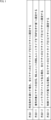
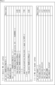
- FIG. 4 is a diagram showing an example of bitstream constraints; FIG. 4 is a diagram showing an example of bitstream constraints; FIG. 4 is a diagram showing an example of syntax; It is a figure which shows the example of a change of a standard.
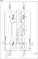
- 1 is a block diagram showing a main configuration example of an encoding device;
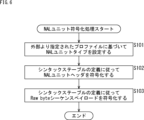
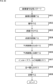
- FIG. 11 is a flowchart illustrating an example of the flow of NAL unit encoding processing;
- FIG. It is a block diagram which shows the main structural examples of a decoding apparatus.
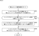
- FIG. 11 is a flowchart showing an example of the flow of NAL unit decoding processing;
- FIG. 1 is a block diagram showing a main configuration example of an encoding device;
- FIG. 10 is a flowchart for explaining an example of the flow of encoding processing
- FIG. 11 is a flowchart illustrating an example of the flow of NAL unit encoding processing
- FIG. It is a block diagram which shows the main structural examples of a decoding apparatus.
- 10 is a flowchart showing an example of the flow of decoding processing
- FIG. 11 is a flowchart showing an example of the flow of NAL unit decoding processing
- FIG. FIG. 4 is a diagram showing an example of bitstream constraints
- FIG. 4 is a diagram showing an example of bitstream constraints
- FIG. 2 shows an example of syntax and semantics
- It is a figure which shows the example of a change of a standard.
- 1 is a block diagram showing a main configuration example of an encoding device;
- FIG. 11 is a flowchart illustrating an example of the flow of NAL unit encoding processing;
- FIG. It is a block diagram which shows the main structural examples of a decoding apparatus.
- 10
- FIG. 10 is a flowchart for explaining an example of the flow of encoding processing
- FIG. 11 is a flowchart illustrating an example of the flow of parameter set encoding processing
- FIG. FIG. 11 is a flowchart for explaining an example of the flow of picture encoding processing
- FIG. It is a block diagram which shows the main structural examples of a decoding apparatus.
- 10 is a flowchart showing an example of the flow of decoding processing
- FIG. 11 is a flowchart showing an example of the flow of parameter set decoding processing
- FIG. FIG. 11 is a flowchart showing an example of the flow of picture decoding processing
- FIG. It is a block diagram which shows the main structural examples of an image coding apparatus.
- 4 is a flowchart showing an example of the flow of image encoding processing; It is a block diagram which shows the main structural examples of an image decoding apparatus. 4 is a flowchart showing an example of the flow of image decoding processing; It is a block diagram which shows the main structural examples of a computer.
- Non-Patent Document 1 (above)
- Non-Patent Document 2 (above)
- Non-Patent Document 3 (above)
- Non-Patent Document 4 (above)
- Non-Patent Document 5 Recommendation ITU-T H.264 (04/2017) "Advanced video coding for generic audiovisual services", April 2017
- Non-Patent Document 6 Recommendation ITU-T H.265 (08/2021) "High efficiency video coding", August 2021
- Non-Patent Document 7 Frank Bossen.
- the content described in the non-patent literature mentioned above is also the basis for determining the support requirements.
- Quad-Tree Block Structure and QTBT (Quad Tree Plus Binary Tree) Block Structure described in the above non-patent literature are not directly described in the examples, they are within the scope of disclosure of the present technology, shall meet the support requirements of the claims.
- technical terms such as Parsing, Syntax, and Semantics are also within the scope of disclosure of the present technology even if they are not directly described in the embodiments, and meet the support requirements for a range of
- the term "block” (not a block indicating a processing unit) used in the description as a partial area of an image (picture) or a processing unit indicates an arbitrary partial area in a picture unless otherwise specified. Its size, shape, characteristics, etc. are not limited.
- the "block” includes TB (Transform Block), TU (Transform Unit), PB (Prediction Block), PU (Prediction Unit), SCU (Smallest Coding Unit), CU (Coding Unit), LCU (Largest Coding Unit), CTB (Coding Tree Block), CTU (Coding Tree Unit), sub-blocks, macro-blocks, tiles, or slices.
- the block size may be specified not only directly but also indirectly.
- the block size may be specified using identification information that identifies the size.
- the block size may be designated by a ratio or a difference from the size of a reference block (for example, LCU or SCU).
- a reference block for example, LCU or SCU.
- the above-mentioned information indirectly specifying a size may be used as the information. By doing so, the information amount of the information can be reduced, and the coding efficiency can be improved in some cases.
- This block size specification also includes block size range specification (for example, block size range specification, etc.).
- Non-Patent Documents 1 to 3 for example, VVC (Versatile Video Coding) and the like have been used as encoding methods for moving images.
- VVC Very Video Coding
- profiles are defined that represent a set of functions defined for each purpose.
- addition of the following profile was proposed as an extended profile of VVC ver.2.
- Main 12 Intra profile, Main 12 4:4:4 Intra profile, and Main 16 4:4:4 Intra profile are also referred to as intra profiles.
- Main 12 Still Picture profile, Main 12 4:4:4 Still Picture profile, and Main 16 4:4:4 Still Picture profile are also referred to as still picture profiles.
- the intra profiles are all picture This profile is designed to encode only I-pictures.
- Still Picture profiles are profiles that use I-pictures to encode still pictures.
- An I-picture also called an intra-picture
- An intra-picture is a picture to which only intra-prediction, which refers to the inside of a screen (inside a region) to generate a predicted image, is applied as prediction processing.
- each picture (each slice) of a moving image is desirably encoded as an I picture (I slice).
- a slice is a unit of data formed within a picture.
- An I slice is a slice to which only intra prediction is applied as prediction processing, similar to an I picture.
- the encoder can encode each picture as a P-picture or B-picture, or encode each picture's slice as a P-slice or B-slice.
- a P-picture (P-slice) and a B-picture (B-slice) are pictures (slices) to which inter-prediction, which refers to other frames to generate a predicted image, can be applied as prediction processing. Therefore, there is a possibility that the bitstream specification does not correspond to the profile.
- ⁇ Method 1-1> For example, when applying method 1, as shown in the second row from the top of the table in FIG. " (Method 1-1).
- IRAPs Intra Random Access Pictures
- NAL unit type By controlling the NAL unit type in this way, the picture type can be more easily limited to I-pictures.
- Method 1-2 For example, when applying method 1, as shown in the third row from the top of the table in FIG. 1, if it is an intra profile, the picture type of all pictures may be limited to I pictures (method 1-2). . By providing such restrictions, it is possible to more reliably encode each picture (each slice) of a moving image as an I picture (I slice) when an intra profile is applied. . Therefore, it is possible to make the bitstream specification compatible with the profile more reliably.
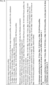
- bitstream restrictions as shown in FIG. 2 may be provided as bitstream restrictions related to intra profiles.
- the NAL unit type (nal_unit_type) is set in the NAL unit header as in the syntax shown in FIG.
- the bitstream constraints in Figure 2 require that this NAL unit type be in the range IDR_W_RADL to CRA_NUT for intra profiles (Main 12 Intra profile, Main 12 4:4:4 Intra profile, or Main 16 4:4:4 Intra profile). is limited to
- nal_unit_type indicates the identification number of the NAL unit type.
- IRAP includes IDR (Instantaneous Decoder Refresh) pictures, CRA (Clean Random Access) pictures, GDR (Gradual Decoding Refresh) pictures, and the like. That is, these values of nal_unit_type are "values that indicate IRAP".
- each picture (each slice) of the video is encoded as an I picture (I slice) when the intra profile is applied.
- I picture I slice
- bitstream constraints in FIG. 2 can be added to "A3.5 Format range extensions profiles" in Non-Patent Document 7.
- FIG. 5 is a block diagram showing an example of a configuration of an encoding device, which is one aspect of an image processing device to which the present technology is applied.
- the encoding device 100 shown in FIG. 5 is a device that encodes a moving image to be encoded and generates a bitstream.
- the encoding device 100 derives a prediction residual of a moving image and its predicted image, performs coefficient transformation (for example, orthogonal transformation) on the prediction residual, quantizes the transformation coefficient, and encodes it.
- coefficient transformation for example, orthogonal transformation
- this encoding method is an example.
- the method of encoding a moving image by the encoding device 100 is not limited to this example. For example, some of the above-described processes, such as coefficient transform and quantization, may be skipped (omitted).
- the encoding device 100 encodes a moving image by applying method 1, method 1-1, method 1-2, or a combination thereof.
- FIG. 5 shows main elements such as the processing unit and data flow, and what is shown in FIG. 5 is not necessarily all.
- the encoding device 100 may have processing units that are not shown as blocks in FIG.
- the encoding apparatus 100 may have processes and data flows not indicated by arrows or the like in FIG.
- encoding device 100 has NAL unit encoding section 101 .
- NAL unit coding section 101 performs processing related to coding of NAL units to be stored in a bitstream.
- NAL unit encoding section 101 acquires arbitrary parameters, forms NAL units for a video to be encoded using the parameters, and encodes the NAL units.
- NAL unit coding section 101 can also be said to be a picture coding section that codes the picture of the video.
- NAL unit encoding section 101 encodes NAL units by applying method 1, method 1-1, method 1-2, or a combination thereof described above.
- NAL unit coding section 101 has NAL unit header setting section 111, NAL unit header coding section 112, and Raw Byte sequence payload coding section 113.
- the NAL unit header setting section 111 sets the NAL unit header (NAL unit header) using the parameters supplied to the NAL unit coding section 101 and supplies it to the NAL unit header coding section 112 .
- the NAL unit header encoding section 112 encodes the NAL unit header supplied from the NAL unit header setting section 111 according to the definition of the syntax table.
- the Raw Byte sequence payload encoding unit 113 encodes the Raw Byte sequence payload according to the definition of the syntax table.
- the NAL unit encoding section 101 (NAL unit header setting section 111) having such a configuration performs processing by applying method 1, method 1-1, method 1-2, or a combination thereof. That is, NAL unit encoding section 101 encodes a moving image according to the bitstream constraints regarding the intra profile described above. For example, when a predetermined condition is satisfied, NAL unit coding section 101 codes the video to be coded with the picture type of all pictures as I-pictures. For example, NAL unit coding section 101 may code the video according to the bitstream constraints shown in FIG.
- NAL unit encoding section 101 sets the NAL unit type of all VCL NAL units to "value indicating IRAP", thereby setting the picture type of all pictures to I picture. good too. That is, if a predetermined condition is satisfied, NAL unit coding section 101 may set the NAL unit type of all VCL NAL units to "value indicating IRAP" and code the video. For example, in the case of VVC, the NAL unit encoding section 101 (NAL unit header setting section 111) may set nal_unit_type to any value from 7 to 11.
- NAL unit encoding section 101 may set the "predetermined condition" that the video encoding profile is an intra profile. That is, when the video encoding profile is the intra profile, NAL unit encoding section 101 may encode the video with the picture type of all pictures as I-pictures. In other words, NAL unit encoding section 101 (NAL unit header setting section 111) may set the NAL unit type of all VCL NAL units to "a value indicating IRAP" when the profile is an intra profile.
- the NAL unit encoding unit 101 determines that the profile is Main 12 Intra profile, Main 12 4:4:4 Intra profile, or Main 16 4:4:4 Intra profile. , may be an intra-profile. That is, if the profile is Main 12 Intra profile, Main 12 4:4:4 Intra profile, or Main 16 4:4:4 Intra profile, NAL unit encoding section 101 (NAL unit header setting section 111)
- the picture type of the picture may be I-picture.
- NAL unit encoding section 101 may determine which profile is using a profile identifier (general_profile_idc) for identifying the profile.
- the profile identifier values corresponding to Main 12 Intra profile, Main 12 4:4:4 Intra profile, and Main 16 4:4:4 Intra profile are set to 10, 42, and 44, respectively. , and may be any value within a practicable range.
- NAL unit encoding section 101 may handle the still picture profile in the same way as the intra profile.
- NAL unit coding section 101 may set the picture type of all pictures to I-picture even when the profile is still picture profile, as in the case of intra profile.
- the NAL unit encoding unit 101 sets the profile to Main 12 Still Picture profile, Main 12 4:4:4 Still Picture profile, or Main 16 4:4:4 Still Picture profile.
- a thing may be a still picture profile. That is, the profile of the NAL unit encoding unit 101 (NAL unit header setting unit 111) is Main 12 Still Picture profile, Main 12 4:4:4 Still Picture profile, or Main 16 4:4:4 Still Picture profile.
- the picture type of all pictures may be I-picture.
- NAL unit coding section 101 NAL unit header setting section 111 may set the picture type of all pictures as I pictures.
- the profile identifier values corresponding to Main 12 Still Picture profile, Main 12 4:4:4 Still Picture profile, and Main 16 4:4:4 Still Picture profile are set to 66, 98, and 100, respectively.
- the encoding apparatus 100 can apply bitstream constraints such as "if a predetermined condition is satisfied, encode the video to be encoded with the picture type of all pictures as I-pictures".
- a moving image can be encoded according to
- the encoding device 100 can encode moving images according to the bitstream constraints shown in FIG. In other words, the encoding apparatus 100 can more reliably match the bitstream specifications to the profile.
- the NAL unit header setting section 111 of the encoding device 100 sets the NAL unit type based on the externally specified profile in step S101. At that time, NAL unit header setting section 111 may set the NAL unit type by applying method 1, method 1-1, method 1-2, or a combination thereof.
- the NAL unit header setting section 111 may set the picture type of all pictures to I picture if a predetermined condition is satisfied. Also, if the condition is satisfied, the NAL unit header setting section 111 may set the NAL unit type of all VCL NAL units to "value indicating IRAP". Further, when the video encoding profile is an intra profile, the NAL unit header setting section 111 may set the picture type of all pictures to I-picture. At that time, the NAL unit header setting unit 111 determines whether the profile is "Main 12 Intra profile, Main 12 4:4:4 Intra profile, or Main 16 4:4:4 Intra profile", or "Intra profile". It can be said that Also, a profile identifier (general_profile_idc) may be used to determine whether it is an intra profile. Also, in the case of the still picture profile, the NAL unit types may be restricted as in the case of the intra profile.
- step S102 the NAL unit header encoding unit 112 encodes the NAL unit header set in step S101 according to the definition of the syntax table.
- the Raw Byte sequence payload encoding unit 113 encodes the Raw byte sequence payload according to the definition of the syntax table. That is, the Raw Byte sequence payload encoding unit 113 encodes the Raw byte sequence payload as a NAL unit of the NAL unit type set in step S101. That is, the Raw Byte sequence payload encoding unit 113 applies the above-described method 1, method 1-1, method 1-2, or a combination thereof so as to satisfy the above-described bitstream constraint on the intra profile (that Encode the Raw byte sequence payload, subject to bitstream constraints).
- step S103 ends, the encoding process ends.
- the encoding device 100 can encode a moving image according to the bitstream constraints shown in FIG. 2, for example. In other words, the encoding apparatus 100 can more reliably match the bitstream specifications to the profile.
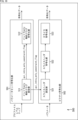
- FIG. 7 is a block diagram showing an example of a configuration of a decoding device, which is one aspect of an image processing device to which the present technology is applied.
- a decoding device 200 shown in FIG. 7 is a device that decodes a bitstream and generates (restores) a moving image to be encoded.
- the decoding device 200 decodes the bitstream to generate (restore) quantized coefficients, dequantizes the quantized coefficients to derive transform coefficients, and converts the transform coefficients to inverse coefficient transform (for example, inverse orthogonal transform). ) to derive a prediction residual, generate a predicted image from the decoded image, and add the predicted image to the prediction residual to generate (restore) image data.
- this decoding method is an example.
- the bitstream decoding method by the decoding device 200 is not limited to this example. For example, some of the above-described processes such as inverse quantization and inverse coefficient transform may be skipped (omitted).
- the decoding device 200 corresponds to the encoding method applied by the encoding device 100. That is, the decoding device 200 performs decoding processing by applying a decoding method corresponding to the encoding method. In other words, the decoding device 200 can decode a bitstream generated by an image processing device (for example, the encoding device 100) to which the present technology is applied. Therefore, the decoding device 200 applies the above method 1, method 1-1, method 1-2, or a combination thereof to decode the bitstream. More specifically, the decoding device 200 checks whether or not the bitstream to be decoded satisfies the above-described bitstream constraints regarding the intra profile (decodes the bitstream while checking).
- FIG. 7 shows main elements such as the processing unit and data flow, and what is shown in FIG. 7 is not necessarily all. That is, the decoding device 200 may have processing units not shown as blocks in FIG. Also, the decoding device 200 may have processes and data flows that are not shown as arrows or the like in FIG.
- decoding device 200 has NAL unit decoding section 201 .
- the NAL unit decoding section 201 performs processing related to decoding of NAL units stored in a bitstream.
- NAL unit decoding section 201 acquires and decodes the bitstream supplied to decoding device 200, generates (restores) NAL units, and outputs parameters related to the NAL units.
- the NAL unit decoding unit 201 can also be said to be a picture decoding unit that decodes the bitstream and generates (restores) pictures of the video.
- NAL unit decoding section 201 applies Method 1, Method 1-1, Method 1-2, or a combination thereof to decode the bitstream and generate (restore) NAL units.
- the NAL unit decoding section 201 has a NAL unit header decoding section 211, a bitstream constraint checking section 212, and a Raw Byte sequence payload decoding section 213.
- the NAL unit header decoding unit 211 decodes the bitstream supplied to the NAL unit encoding unit 101, generates (restores) the NAL unit header, and supplies it to the bitstream constraint checking unit 212.
- the bitstream constraint checking unit 212 uses the parameters included in the generated NAL unit header to check whether the bitstream to be decoded satisfies the bitstream constraints. At this time, the bitstream constraint checker 212 performs the check by applying the method 1, method 1-1, method 1-2, or a combination thereof. That is, the bitstream constraint checking unit 212 checks whether or not the bitstream to be decoded satisfies the bitstream constraint regarding the intra profile described above (decodes the bitstream while checking).
- the bitstream constraint checking unit 212 may check whether the picture type of all pictures in the moving image is an I picture in the bitstream to be decoded. For example, the bitstream constraint checker 212 may check whether the bitstream to be decoded satisfies the bitstream constraints shown in FIG.
- the bitstream constraint checking unit 212 may check whether the NAL unit type of all VCL NAL units is "value indicating IRAP" in the bitstream to be decoded. For example, in the case of VVC, the bitstream constraint checking unit 212 may check whether nal_unit_type is set to any value from 7 to 11 in the NAL unit header.
- the bitstream constraint checking unit 212 may check whether the picture type of all pictures in the bitstream to be decoded is I-picture. In other words, if the profile is an intra profile, the bitstream constraint checking unit 212 checks whether the NAL unit type of all VCL NAL units is set to "value indicating IRAP" in the NAL unit header. good too.
- the bitstream constraint confirmation unit 212 determines that the profile is Main 12 Intra profile, Main 12 4:4:4 Intra profile, or Main 16 4:4:4 Intra profile, even if it is an intra profile. good. That is, when the profile is Main 12 Intra profile, Main 12 4:4:4 Intra profile, or Main 16 4:4:4 Intra profile, the bitstream constraint checking unit 212 checks all You may check if the picture type of the picture is an I picture.
- bitstream constraint confirmation unit 212 may determine which profile is using a profile identifier (general_profile_idc) for identifying the profile. That is, when the value of this profile identifier is 10, 42, or 44, the bitstream constraint checking unit 212 checks whether the picture type of all pictures in the bitstream to be decoded is I-picture. good.
- a profile identifier generally_profile_idc
- bitstream constraint checking unit 212 may handle the still picture profile in the same way as the intra profile. That is, even when the profile is the still picture profile, the bitstream constraint checking unit 212 checks whether the picture type of all pictures in the bitstream to be decoded is I-picture, as in the case of the intra profile. may
- the bitstream constraint checking unit 212 confirms that the profile is Main 12 Still Picture profile, Main 12 4:4:4 Still Picture profile, or Main 16 4:4:4 Still Picture profile with the still picture profile. It can be a certain thing. That is, if the profile is Main 12 Still Picture profile, Main 12 4:4:4 Still Picture profile, or Main 16 4:4:4 Still Picture profile, the bitstream constraint checking unit 212 determines , it may check whether the picture type of all pictures is I-picture. At this time, if the value of this profile identifier is 66, 98, or 100, the bitstream constraint checking unit 212 checks whether the picture type of all pictures in the bitstream to be decoded is I-picture. good too.
- the bitstream constraint confirmation unit 212 may output the confirmation result as described above. For example, if the bitstream constraint checking unit 212 determines that the bitstream does not satisfy the bitstream constraints corresponding to method 1, method 1-1, method 1-2, or a combination thereof, the bitstream constraint may be notified to the user or the like with a warning message indicating that the For example, the bitstream constraint confirmation unit 212 may display the warning message as text or an image on the screen, or may output the warning message as audio from a speaker or the like. Also, the bitstream constraint checking unit 212 may provide the warning message as data or the like to another device, another processing unit (another application), or the like.
- bitstream constraint checking unit 212 may control bitstream decoding based on the checking result. For example, if the bitstream constraint checking unit 212 determines that the bitstream does not satisfy the bitstream constraints corresponding to method 1, method 1-1, method 1-2, or a combination thereof, the bitstream may be terminated. In addition, if the bitstream constraint checking unit 212 determines that the bitstream does not satisfy the bitstream constraints corresponding to the above-described method 1, method 1-1, method 1-2, or a combination thereof, the user or the like The bitstream decoding process may be paused until authorized.
- bitstream constraint checking unit 212 may output both a warning message and control the decoding process.
- the Raw Byte sequence payload decoding unit 213 decodes the bitstream based on the parameters included in the generated NAL unit header and derives the Raw Byte sequence payload. Therefore, the Raw Byte sequence payload decoding unit 213 can also be said to be a picture decoding unit that decodes the bitstream of the moving image to be decoded.
- the decoding device 200 can encode the video to be encoded with the picture type of all pictures as I-pictures when the bitstream to be decoded satisfies a predetermined condition. It is possible to check whether the bitstream constraints such as "do" are satisfied. For example, the decoding device 200 can check whether the bitstream to be decoded satisfies the bitstream constraints shown in FIG. In other words, the decoding device 200 can make the specification of the bitstream to be decoded correspond to the profile more reliably.
- the NAL unit header decoding unit 211 of the decoding device 200 decodes the encoded data of the NAL unit header according to the definition of the syntax table in step S201.
- step S202 the bitstream constraint checking unit 212 determines whether the bitstream satisfies the bitstream constraint regarding the intra profile. At that time, the bitstream constraint checker 212 may perform the check by applying the method 1, method 1-1, method 1-2, or a combination thereof.
- the bitstream constraint checking unit 212 may check whether the picture type of all pictures in the moving image is an I picture in the bitstream to be decoded. Also, if the condition is satisfied, the bitstream constraint checker 212 may check whether the NAL unit type of all VCL NAL units in the bitstream is "value indicating IRAP". For example, you may check that the nal_unit_type is one of 7 to 11 as follows.
- the bitstream constraint checking unit 212 may check whether the picture type of all pictures in the bitstream is I-picture.
- the bitstream constraint confirmation unit 212 checks that the profile is "Main 12 Intra profile, Main 12 4:4:4 Intra profile, or Main 16 4:4:4 Intra profile", "Intra profile It can be said that Also, a profile identifier (general_profile_idc) may be used to determine whether it is an intra profile. Also, in the case of the still picture profile, as in the case of the intra profile, it may be checked whether the picture type of all pictures in the bitstream to be decoded is I-picture.
- step S203 the bitstream constraint confirmation unit 212 notifies a warning message indicating that the bitstream constraint regarding the intra profile is not satisfied.
- step S203 When the process of step S203 ends, the process proceeds to step S204. Also, if it is determined in step S202 that the bitstream to be decoded satisfies the bitstream constraint regarding the intra profile, the process proceeds to step S204.
- step S204 the Raw Byte sequence payload decoding unit 213 decodes the Raw byte sequence payload according to the definition of the syntax table.
- step S204 ends, the decoding process ends.
- the decoding device 200 can convert the bitstream to be decoded into a moving image to be encoded with the picture type of all pictures as I-pictures when a predetermined condition is satisfied. You can check if the bitstream constraints such as "encode" are satisfied. For example, the decoding device 200 can check whether the bitstream to be decoded satisfies the bitstream constraints shown in FIG. In other words, the decoding device 200 can make the specification of the bitstream to be decoded correspond to the profile more reliably.
- the picture type of all pictures may be limited to I pictures (method 1-3). .
- I pictures Method 1-3
- each picture (each slice) of a video is more reliably encoded as an I picture (I slice) even if it is not an intra profile. be able to. Therefore, it is possible to make the bitstream specification compatible with the profile more reliably.
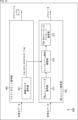
- FIG. 9 is a block diagram showing a main configuration example of encoding apparatus 100 in that case (when method 1-3 is applied). Note that FIG. 9 shows main components such as processing units and data flow, and the components shown in FIG. 9 are not necessarily all of them. In other words, the encoding device 100 may have processing units that are not shown as blocks in FIG. Also, the encoding apparatus 100 may have processes and data flows not indicated by arrows or the like in FIG.
- encoding device 100 in this case has parameter set encoding section 301 in addition to the configuration of FIG.
- a parameter set encoding unit 301 acquires a parameter set including parameters such as profile, level, tier, etc., encodes it, and outputs the encoded data (stores it in a bitstream).
- the parameter set encoding unit 301 may apply the method 1-3 described above to perform processing.
- the parameter set encoding unit 301 sets a control flag (irap_only_constraint_flag) for controlling whether to limit the picture type of all pictures of the video to I pictures, encodes the set control flag, and bit May be stored in a stream.
- parameter set encoding section 301 has control flag setting section 311 and control flag encoding section 312 .
- the control flag setting unit 311 sets a control flag (irap_only_constraint_flag).
- the control flag setting unit 311 sets this control flag, for example, based on an instruction from a user or the like. Then, the control flag setting section 311 supplies the set control flag to the control flag encoding section 312 . Also, the control flag setting section 311 supplies the set control flag to the NAL unit header setting section 111 .
- the control flag encoding unit 312 encodes the control flag and outputs the encoded data (stores it in the bitstream).
- the NAL unit encoding section 101 applies method 1-3 described above and performs processing based on this control flag. For example, if this control flag is true, NAL unit coding section 101 may code the video with the picture type of all pictures as I-pictures. At that time, NAL unit encoding section 101 (NAL unit header setting section 111) sets the NAL unit type of all VCL NAL units to "value indicating IRAP", thereby setting the picture type of all pictures to I picture. good too. For example, in the case of VVC, the NAL unit encoding section 101 (NAL unit header setting section 111) may set nal_unit_type to any value from 7 to 11.
- the NAL unit header encoding section 112 and the Raw Byte sequence payload encoding section 113 perform the same processing as in FIG.
- the encoding apparatus 100 when the control flag (irap_only_constraint_flag) for controlling whether to limit the picture type of all pictures of a moving image to I-pictures is true, allows all pictures A moving image to be encoded can be encoded with the picture type of I-picture as an I-picture. In other words, the encoding apparatus 100 can more reliably match the bitstream specifications to the profile.
- step S301 the control flag setting unit 311 of the encoding device 100 sets the picture type of all pictures of the moving image to I picture based on an instruction from the user or the like. Set a control flag (irap_only_constraint_flag) to control whether to restrict.
- step S302 the control flag encoding unit 312 encodes the control flag (irap_only_constraint_flag) set in step S301 and stores it in the bitstream.
- step S303 the NAL unit encoding unit 101 applies method 1-3 described above, executes NAL unit encoding processing based on the control flag (irap_only_constraint_flag) set in step S301, and encodes the NAL unit. do.
- control flag irap_only_constraint_flag
- NAL unit coding section 101 codes the video with the picture type of all pictures as I-pictures.
- step S303 When the process of step S303 ends, the encoding process ends.
- the NAL unit header setting section 111 sets the NAL unit type based on the control flag (irap_only_constraint_flag) in step S321. For example, if the control flag is true, NAL unit header setting section 111 sets the picture type of all pictures as I pictures. For example, in that case, the NAL unit header setting section 111 may set the NAL unit type of all VCL NAL units to "value indicating IRAP". For example, in the case of VVC, the NAL unit header setting section 111 may set nal_unit_type to any value from 7 to 11.
- step S322 the NAL unit header encoding unit 112 encodes the NAL unit header set in step S301 according to the definition of the syntax table.
- the Raw Byte sequence payload encoding unit 113 encodes the Raw byte sequence payload according to the definition of the syntax table. That is, the Raw Byte sequence payload encoding unit 113 encodes the Raw byte sequence payload as a NAL unit of the NAL unit type set in step S321. That is, Raw Byte sequence payload encoding section 113 applies the method 1-3 described above to encode the Raw byte sequence payload.
- step S323 When the process of step S323 ends, the NAL unit encoding process ends, and the process returns to FIG.
- the encoding apparatus 100 can control whether the picture type of all pictures in the moving image is limited to I-pictures.
- a moving image to be encoded can be encoded by setting the picture type of the picture in I-picture to I-picture. In other words, the encoding apparatus 100 can more reliably match the bitstream specifications to the profile.
- FIG. 12 is a block diagram showing a main configuration example of a decoding device in this case (when method 1-3 is applied). Note that FIG. 12 shows main components such as processing units and data flow, and the components shown in FIG. 12 are not necessarily all. That is, the decoding device 200 may have processing units not shown as blocks in FIG. Also, the decoding device 200 may have processes and data flows not indicated by arrows or the like in FIG. 12 .
- decoding device 200 in this case has parameter set decoding section 401 in addition to the configuration in FIG.
- the parameter set decoding unit 401 acquires coded data of a parameter set including parameters such as profile, level, tier, etc. stored in a bitstream, decodes it, and converts the parameter set (for example, profile, level, tier, etc.) parameters) are generated (restored).
- the parameter set decoding unit 401 has a control flag decoding unit 411.
- the control flag decoding unit 411 applies the method 1-3 described above, decodes the bitstream, and sets a control flag (irap_only_constraint_flag) for controlling whether the picture type of all pictures of the moving image is limited to I pictures. generate (restore)
- the control flag decoder 411 supplies the generated control flag to the bitstream constraint checker 212 .
- the bitstream constraint checking unit 212 may check whether the NAL unit type of all VCL NAL units is "value indicating IRAP" in the bitstream to be decoded. For example, in the case of VVC, the bitstream constraint checking unit 212 may check whether nal_unit_type is set to any value from 7 to 11 in the NAL unit header.
- the bitstream constraint confirmation unit 212 may output the confirmation result as described above. For example, if the bitstream constraint checking unit 212 determines that the bitstream does not satisfy the bitstream constraint corresponding to the method 1-3 described above, a warning message indicating that the bitstream constraint is not satisfied is sent to the user or the like. may notify you. For example, the bitstream constraint confirmation unit 212 may display the warning message as text or an image on the screen, or may output the warning message as audio from a speaker or the like. Also, the bitstream constraint checking unit 212 may provide the warning message as data or the like to another device, another processing unit (another application), or the like.
- the bitstream constraint checking unit 212 may control bitstream decoding based on the checking result. For example, when the bitstream constraint checking unit 212 determines that the bitstream does not satisfy the bitstream constraint corresponding to the methods 1-3 described above, the bitstream decoding process may be terminated. Further, if the bitstream constraint checking unit 212 determines that the bitstream does not satisfy the bitstream constraint corresponding to the method 1-3 described above, the bitstream constraint checking unit 212 temporarily suspends the decoding process of the bitstream until it is permitted by the user or the like. You can stop.
- bitstream constraint checking unit 212 may output both a warning message and control the decoding process.
- the NAL unit header decoding unit 211 and the Raw Byte sequence payload decoding unit 213 perform the same processing as in FIG.
- the decoding device 200 when the control flag (irap_only_constraint_flag) for controlling whether to limit the picture type of all pictures of the moving image to I pictures is true, the bits to be decoded In the stream, it is possible to check whether the picture type of all pictures is I-picture. In other words, the decoding device 200 can make the specification of the bitstream to be decoded correspond to the profile more reliably.
- the control flag irap_only_constraint_flag
- control flag decoding unit 411 of the decoding device 200 decodes (encoded data of control flags included in) the bitstream in step S401, and decodes all pictures of the moving image. Generate (restore) a control flag (irap_only_constraint_flag) for controlling whether the picture type is limited to I pictures.
- step S402 the NAL unit decoding unit 201 executes the NAL unit encoding process by applying the method 1-3 described above, and extracts the NAL unit based on the control flag (irap_only_constraint_flag) generated (restored) in step S401. Decode the encoded data. That is, when the control flag is true, NAL unit coding section 101 checks whether the picture type of all pictures in the bitstream to be decoded is I-picture.
- step S402 ends, the decoding process ends.
- the NAL unit header decoding section 211 decodes the encoded data of the NAL unit header according to the definition of the syntax table in step S421.
- step S422 the bitstream constraint checking unit 212 determines whether or not the bitstream to be decoded satisfies the bitstream constraint regarding the intra profile. At that time, the bitstream constraint checking unit 212 may perform the checking by applying the method 1-3 described above.
- the bitstream constraint checker 212 may check whether the NAL unit type of all VCL NAL units in the bitstream is "value indicating IRAP". For example, in the case of VVC, the bitstream constraint checking unit 212 may check that the nal_unit_type is any one of 7 to 11.
- step S423 the bitstream constraint confirmation unit 212 notifies a warning message indicating that the bitstream constraint regarding the intra profile is not satisfied.
- step S423 When the process of step S423 ends, the process proceeds to step S424. Also, if it is determined in step S422 that the bitstream to be decoded satisfies the bitstream constraint regarding the intra profile, the process proceeds to step S424.
- step S424 the Raw Byte sequence payload decoding unit 213 decodes the Raw byte sequence payload according to the definition of the syntax table.
- step S424 ends, the process returns to FIG.
- the decoding device 200 By executing each process in this way, the decoding device 200, if the control flag (irap_only_constraint_flag) for controlling whether to limit the picture type of all pictures of the moving image to I pictures is true, In the bitstream, it is possible to check whether the picture type of all pictures is I-picture. In other words, the decoding device 200 can make the specification of the bitstream to be decoded correspond to the profile more reliably.
- the control flag irap_only_constraint_flag
- encoding device 100 and decoding device 200 apply method 1-3 described above in combination with other methods (method 1, method 1-1, method 1-2, or a combination thereof, etc. described above). may
- the intra only constraint flag may be limited to true (method 2).
- the intra only constraint flag (gci_intra_only_constraint_flag) is flag information indicating whether or not the slice type of all slices of a moving image is I slice. Also, this intra-only constraint flag can be said to be a control flag for controlling whether or not the slice type of all slices of a moving image is limited to I slices.
- this constraint can be applied to, for example, the intra profile described above. That is, it is possible to control whether or not the slice type of all slices of a moving image is limited to I slices via this intra-only constraint flag. Therefore, it is possible to make the bitstream specification compatible with the profile more reliably.
- Method 2-1 For example, when applying method 2, the profiles are Main 12 Intra profile, Main 12 4:4:4 Intra profile, Main 16 4:4:4 Intra profile, as shown in the second row from the top of the table in FIG. , the intra-only constraint flag may be restricted to true (method 2-1).
- Method 2-1-1 For example, when applying method 2-1, as shown in the third row from the top of the table in FIG. (Method 2-1-1).
- Method 2-2 For example, when method 2 is applied, the intra-only constraint flag may be restricted to true even in the case of still picture profiles, as shown at the bottom of the table in FIG. 15 (method 2-2).
- bitstream restrictions as shown in FIG. 16 may be provided as bitstream restrictions related to intra profiles.
- an intra only constraint flag gci_intra_only_constraint_flag
- this intra only constraint flag (gci_intra_only_constraint_flag) is true. is limited to
- FIG. 19 is a block diagram showing an example of the configuration of an encoding device that is one aspect of an image processing device to which the present technology is applied.
- An encoding device 500 shown in FIG. 19 is a device that encodes a moving image to be encoded and generates a bitstream.
- the encoding device 500 derives a prediction residual of a moving image and its predicted image, performs coefficient transformation (for example, orthogonal transformation) on the prediction residual, quantizes the transformation coefficients, and encodes them.
- coefficient transformation for example, orthogonal transformation
- this encoding method is an example.
- the method of encoding a moving image by the encoding device 500 is not limited to this example. For example, some of the above-described processes, such as coefficient transform and quantization, may be skipped (omitted).
- the encoding device 500 encodes a moving image by applying method 2, method 2-1, method 2-1-1, method 2-2, or a combination thereof.
- FIG. 19 shows main elements such as the processing unit and data flow, and the elements shown in FIG. 19 are not necessarily all.
- the encoding device 500 may have processing units that are not shown as blocks in FIG.
- the encoding device 500 may have processes and data flows that are not shown as arrows or the like in FIG.
- encoding device 500 has parameter set encoding section 501 and picture encoding section 502 .
- a parameter set encoding unit 501 acquires a parameter set including parameters such as profile, level, tier, etc., encodes it, and outputs the encoded data (stores it in a bitstream).
- the picture encoding unit 502 acquires arbitrary parameters related to a moving image to be encoded, and uses the parameters to encode the moving image for each slice.
- the parameter set encoding unit 501 and the picture encoding unit 502 apply the above-described method 2, method 2-1, method 2-1-1, method 2-2, or a combination thereof to perform processing. good too.
- the parameter set encoding unit 501 sets an intra-only constraint flag (gci_intra_only_constraint_flag ) to true to encode the parameter set with its intra-only constraint flag.
- the picture encoding unit 502 may encode the video with all slices of the video to be encoded set as I slices.
- the picture encoding unit 502 may set the value of sh_slice_type, which is a parameter indicating the slice type, to "2".
- the parameter set encoding unit 501 sets the intra only constraint flag to true when the profile is Main 12 Intra profile, Main 12 4:4:4 Intra profile, or Main 16 4:4:4 Intra profile. may
- the parameter set encoding unit 501 may set the intra-only restriction flag to true when the value of the profile identifier (general_profile_idc) for identifying the profile is 10, 42, or 44.
- parameter set encoding section 501 also sets the intra-only constraint flag to true when the profile is a still picture profile (for example, when the value of the profile identifier (general_profile_idc) is 66, 98, or 100). You may
- the parameter set encoding unit 501 has an intra-only constraint flag setting unit 511 and an intra-only constraint flag encoding unit 512.
- the picture coding unit 502 also has a slice header setting unit 521 , a slice header coding unit 522 and a slice coding unit 523 .
- the intra-only restriction flag setting unit 511 determines that the profile is Main 12 Intra profile, Main 12 4:4:4 Intra profile, or Main 16 4:4:4 Intra profile as an intra profile. good too. That is, if the specified profile is Main 12 Intra profile, Main 12 4:4:4 Intra profile, or Main 16 4:4:4 Intra profile, the intra only constraint flag setting unit 511 sets the intra only constraint flag to May be set to true.
- the intra-only restriction flag setting unit 511 may determine what the specified profile is by using a profile identifier (general_profile_idc) for identifying the profile. That is, the intra-only restriction flag setting unit 511 may set the intra-only restriction flag to true when the value of this profile identifier is 10, 42, or 44.
- a profile identifier generally_profile_idc
- the intra-only restriction flag setting unit 511 may handle the still picture profile in the same way as the intra profile. That is, the intra-only constraint flag setting unit 511 may set the intra-only constraint flag to true even when the profile is the still picture profile, as in the case of the intra profile.
- the intra-only restriction flag setting unit 511 determines that the profile is Main 12 Still Picture profile, Main 12 4:4:4 Still Picture profile, or Main 16 4:4:4 Still Picture profile. It is also possible to be That is, if the specified profile is Main 12 Still Picture profile, Main 12 4:4:4 Still Picture profile, or Main 16 4:4:4 Still Picture profile, intra only constraint flag setting unit 511 sets intra only Constraint flags may be set to true.
- the intra-only restriction flag setting unit 511 may determine what the specified profile is by using the profile identifier (general_profile_idc) for identifying the profile. That is, the intra-only restriction flag setting unit 511 may set the intra-only restriction flag to true when the value of this profile identifier is 66, 98, or 100.
- FIG. 1 the profile identifier
- the intra-only constraint flag setting unit 511 may supply the set intra-only constraint flag to the intra-only constraint flag encoding unit 512 and the slice header setting unit 521 .
- the intra-only constraint flag encoding unit 512 may encode the intra-only constraint flag supplied from the intra-only constraint flag setting unit 511 and store the encoded data in the bitstream.
- sh_slice_type which is a parameter indicating the slice type
- the slice header setting unit 521 may set the slice type based on the specified profile type instead of the intra-only restriction flag. For example, the slice header setting unit 521 may set all slices as I slices when an intra profile is specified. For example, when Main 12 Intra profile, Main 12 4:4:4 Intra profile, or Main 16 4:4:4 Intra profile is specified, the slice header setting unit 521 sets all slices to I slices. good too. Also, when the value of the specified profile identifier is 10, 42, or 44, the slice header setting unit 521 may set the picture type of all pictures to I-picture. Further, the slice header setting unit 521 may set the picture type of all pictures to I-picture even when a still picture profile is specified.
- the slice header setting unit 521 may supply the slice header set in this way to the slice header encoding unit 522 .
- the slice header encoding unit 522 encodes the slice header supplied from the slice header setting unit 521 according to the definition of the syntax table.
- the slice encoding unit 523 encodes slices according to the definition of the syntax table.
- the encoding device 500 can encode moving images according to bitstream constraints such as "for intra profiles, limit the intra-only constraint flag to true".
- bitstream constraints such as "for intra profiles, limit the intra-only constraint flag to true".
- the encoding device 500 can encode moving images according to the bitstream constraints shown in FIG. In other words, the encoding apparatus 500 can more reliably match the bitstream specifications to the profile.
- the parameter set encoding unit 501 of the encoding device 500 executes the parameter set encoding process and encodes the parameter set in step S501.
- the parameter set encoding unit 501 sets the intra only constraint flag to true, and encodes the parameter set including the intra only constraint flag.
- step S502 the picture encoding unit 502 executes picture encoding processing to encode the picture. At this time, if the intra-only constraint flag is true, the picture encoding unit 502 encodes the video to be encoded with all slices as I-slices.
- step S502 ends, the encoding process ends.
- the intra-only constraint flag setting unit 511 sets the intra-only constraint flag (gci_intra_only_constraint_flag) based on the specified profile in step S521. As described above, for example, when an intra profile is specified, the intra only constraint flag setting unit 511 may set the intra only constraint flag to true. At that time, the intra-only restriction flag setting unit 511 determines that the profile is Main 12 Intra profile, Main 12 4:4:4 Intra profile, or Main 16 4:4:4 Intra profile as an intra profile. good too. Also, the intra-only restriction flag setting unit 511 may determine what the specified profile is by using a profile identifier (general_profile_idc) for identifying the profile. Also, the intra-only restriction flag setting unit 511 may handle the still picture profile in the same manner as the intra profile.
- a profile identifier generally_profile_idc
- step S522 the intra-only constraint flag encoding unit 512 encodes the intra-only constraint flag set in step S521 according to the definition of the syntax table.
- step S522 When the process of step S522 ends, the parameter set encoding process ends, and the process returns to FIG.
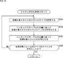
- the slice header setting unit 521 sets the slice type of the slice to be processed in step S541.
- the slice header setting unit 521 may set the slice type based on the specified profile type instead of the intra-only restriction flag. For example, the slice header setting unit 521 may set all slices as I slices when an intra profile is specified. For example, when Main 12 Intra profile, Main 12 4:4:4 Intra profile, or Main 16 4:4:4 Intra profile is specified, the slice header setting unit 521 sets all slices to I slices. good too. Also, when the value of the specified profile identifier is 10, 42, or 44, the slice header setting unit 521 may set the picture type of all pictures to I-picture. Further, the slice header setting unit 521 may set the picture type of all pictures to I-picture even when a still picture profile is specified.
- the slice header setting unit 521 sets a slice header including the slice type set in this way for the slice to be processed.
- step S542 the slice header encoding unit 522 encodes the slice header of the processing target slice set in step S541 according to the definition of the syntax table.
- step S543 the slice encoding unit 523 encodes the slice to be processed according to the definition of the syntax table.
- step S544 the picture coding unit 502 determines whether or not all slices of the processing target frame have been coded. If it is determined that there are unprocessed slices, a new slice to be processed is selected from among the unprocessed slices, and the process returns to step S541. That is, each process of steps S541 to S544 is executed for each slice of the processing target frame.
- step S544 if it is determined that all slices of the frame to be processed have been encoded, the picture encoding process ends, and the process returns to FIG.
- the encoding device 500 can encode a moving image according to a bitstream constraint such as "for an intra profile, limit the intra-only constraint flag to true".
- a bitstream constraint such as "for an intra profile, limit the intra-only constraint flag to true".
- the encoding device 500 can encode moving images according to the bitstream constraints shown in FIG. In other words, the encoding apparatus 500 can more reliably match the bitstream specifications to the profile.
- FIG. 23 is a block diagram showing an example of a configuration of a decoding device which is one aspect of an image processing device to which the present technology is applied.
- a decoding device 600 shown in FIG. 23 is a device that decodes a bitstream and generates (restores) a moving image to be encoded.
- the decoding device 600 decodes the bitstream to generate (restore) quantized coefficients, dequantizes the quantized coefficients to derive transform coefficients, and converts the transform coefficients to inverse coefficient transform (for example, inverse orthogonal transform). ) to derive a prediction residual, generate a predicted image from the decoded image, and add the predicted image to the prediction residual to generate (restore) image data.
- inverse coefficient transform for example, inverse orthogonal transform
- this decoding method is an example.
- the bitstream decoding method by the decoding device 600 is not limited to this example. For example, some of the above-described processes such as inverse quantization and inverse coefficient transform may be skipped (omitted).
- the decoding device 600 decodes the bitstream by applying method 2, method 2-1, method 2-1-1, method 2-2, or a combination thereof.
- FIG. 23 shows main elements such as the processing unit and data flow, and what is shown in FIG. 23 is not necessarily all. That is, the decoding device 600 may have processing units not shown as blocks in FIG. Also, the decoding device 600 may have processes and data flows not indicated by arrows or the like in FIG.
- decoding device 600 has parameter set decoding section 601 and picture decoding section 602 .
- a parameter set decoding unit 601 obtains coded data of a parameter set including parameters such as profile, level, and tier stored in a bitstream, decodes it, and decodes the parameter set (for example, profile, level, tier, etc.). parameters) are generated (restored).
- a picture decoding unit 602 acquires a bitstream, decodes the bitstream, generates (restores) a moving image to be encoded, and outputs parameters related to the moving image.
- the parameter set decoding unit 601 has an intra-only constraint flag decoding unit 611 and a bitstream constraint checking unit 612.
- the picture decoding unit 602 also has a slice header decoding unit 621 , a bitstream constraint checking unit 622 and a slice decoding unit 623 .
- the intra only constraint flag decoding unit 611 applies the above-described method 2, method 2-1, method 2-1-1, method 2-2, or a combination thereof, decodes the bitstream, and decodes the intra only constraint flag ( gci_intra_only_constraint_flag) is generated (restored).
- the intra-only constraint flag is a control flag that controls whether the slice types of all slices of a moving image are limited to I-slices. Therefore, the intra-only constraint flag decoding unit 611 can also be said to be a control flag decoding unit. Note that the intra-only constraint flag can also be said to be flag information indicating whether or not the slice type of all slices of a moving image stored in a bitstream is an I slice.
- the intra-only constraint flag decoder 611 supplies the generated intra-only constraint flag to the bitstream constraint checker 612 and the bitstream constraint checker 622 .
- bitstream constraint checking unit 612 determines that the intra only constraint flag is true. You can check if it is
- bitstream constraint checking unit 612 may check whether the intra-only constraint flag is true when the value of the profile identifier (general_profile_idc) for identifying the profile is 10, 42, or 44.
- bitstream constraint checking unit 612 may further check whether the intra-only constraint flag is true even when the profile of the bitstream is the still picture profile.
- the bitstream constraint confirmation unit 612 may output the confirmation result as described above. For example, the bitstream constraint checking unit 612 determines that the bitstream does not satisfy the bitstream constraint related to the intra-only constraint flag described above (there is an intra-only constraint flag whose value is false even though it is an intra profile). If so, the user or the like may be notified of a warning message indicating that the bitstream constraint is not satisfied. For example, the bitstream constraint confirmation unit 612 may display the warning message as text or an image on the screen, or may output the warning message as audio from a speaker or the like. Also, the bitstream constraint checking unit 612 may provide the warning message as data or the like to another device, another processing unit (another application), or the like.
- the bitstream constraint checker 612 may control decoding of the intra-only constraint flag based on the check result. For example, when the bitstream constraint checking unit 612 determines that the bitstream does not satisfy the bitstream constraint related to the intra-only constraint flag described above, the decoding process for the intra-only constraint flag may be terminated. Further, when the bitstream constraint checking unit 612 determines that the bitstream does not satisfy the bitstream constraint related to the intra-only constraint flag described above, the decoding processing of the intra-only constraint flag is temporarily suspended until the user or the like permits it. You can stop.
- bitstream constraint checking unit 612 may both output a warning message and control the decoding process.
- the slice header decoding unit 621 decodes the bitstream according to the definition of the syntax table and generates (restores) the slice header of the slice to be processed.
- the slice header decoding unit 621 supplies the generated slice header of the slice to be processed to the bitstream constraint checking unit 622 .
- the bitstream constraint confirmation unit 622 performs processing related to confirmation of bitstream constraints.
- the bitstream constraint checker 622 may obtain the intra-only constraint flag supplied from the intra-only constraint flag decoder 611 .
- the bitstream constraint checking unit 622 may acquire the slice header supplied from the slice header decoding unit 621 .
- the bitstream constraint checking unit 622 applies the above-described method 2, method 2-1, method 2-1-1, method 2-2, or a combination thereof, and if a predetermined condition is satisfied, in the bitstream, It may be checked whether the slice type of all slices of the moving image is I-slice.
- the bitstream constraint checking unit 622 may check whether or not the value of sh_slice_type, which is a parameter indicating the slice type, is "2" for all slices.
- the bitstream constraint checking unit 622 may check whether the slice type of all the slices of the video in the bitstream is I slice. For example, if the intra-only constraint flag supplied from the intra-only constraint flag decoding unit 611 is true, the bitstream constraint checking unit 622 determines whether the slice type of all slices of the video in the bitstream is an I slice. can be checked.
- the bitstream constraint checking unit 622 may check whether the slice type of all slices is I slice based on the profile type of the bitstream instead of the intra-only constraint flag. For example, when the profile of the bitstream is the intra profile, the bitstream constraint checking unit 622 may check whether the slice type of all slices of the video in the bitstream is I slice. For example, if the profile type of the bitstream is Main 12 Intra profile, Main 12 4:4:4 Intra profile, or Main 16 4:4:4 Intra profile, the bitstream constraint checking unit 622 checks all slice slices You may check if the type is an I slice.
- the bitstream constraint checker 622 may check whether the slice type of all slices is I slice.
- the bitstream constraint checking unit 622 may also check whether the slice type of all slices is an I slice even when the bitstream profile is the still picture profile.
- the bitstream constraint confirmation unit 622 may output the confirmation result as described above. For example, if the bitstream constraint checking unit 622 determines that the bitstream does not satisfy the bitstream constraint related to the intra-only constraint flag described above (there is a slice that is not an I slice even though it is an intra profile), the bitstream A user or the like may be notified of a warning message indicating that the stream constraint is not satisfied. For example, the bitstream constraint confirmation unit 622 may display the warning message as text or an image on the screen, or may output the warning message as audio from a speaker or the like. Also, the bitstream constraint checking unit 622 may provide the warning message as data or the like to another device, another processing unit (another application), or the like.
- bitstream constraint checker 622 may control decoding of the intra-only constraint flag based on the check result. For example, when the bitstream constraint checking unit 622 determines that the bitstream does not satisfy the bitstream constraint related to the intra-only constraint flag described above, the bitstream decoding process may be terminated. If the bitstream constraint checking unit 622 determines that the bitstream does not satisfy the bitstream constraint related to the intra-only constraint flag described above, the bitstream constraint checking unit 622 suspends the decoding process of the bitstream until the user or the like permits it. may
- bitstream constraint confirmation unit 622 may output both a warning message and control the decoding process.
- the slice decoding unit 623 decodes the bitstream and generates (restores) a moving image to be decoded included in the bitstream. For example, the slice decoding unit 623 decodes the target slice according to the definition of the syntax table.
- the decoding device 600 can confirm whether all intra-only constraint flags are true, for example, when the profile of the bitstream is an intra profile. In other words, the decoding device 600 can make the specification of the bitstream to be decoded correspond to the profile more reliably.
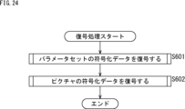
- the parameter set decoding unit 601 executes the parameter decoding process in step S601, decodes the coded data of the parameter set included in the bitstream, and generates (restores) the parameter set. )do.
- step S602 the picture decoding unit 602 executes picture decoding processing, decodes encoded data of pictures included in the bitstream, and generates (restores) pictures.
- step S602 ends, the decoding process ends.
- the intra-only constraint flag decoding unit 611 decodes the bitstream according to the definition of the syntax table and generates (restores) the intra-only constraint flag in step S621.
- step S623 the bitstream constraint confirmation unit 612 notifies a warning message indicating that the bitstream constraint regarding the intra-only constraint flag is not satisfied.
- step S623 ends, the parameter set decoding process ends, and the process returns to FIG. If it is determined in step S622 that the intra-only constraint flag is true, the parameter set decoding process ends and the process returns to FIG.
- the slice header decoding unit 621 decodes the bitstream according to the definition of the syntax table in step S641 to generate (restore) the slice header of the slice to be processed.
- step S642 the bitstream constraint checking unit 622 applies method 2, method 2-1, method 2-1-1, method 2-2, or a combination thereof described above to determine if the bitstream is related to the intra-only constraint flag. Determine whether the bitstream constraints are satisfied. For example, if a predetermined condition is satisfied, the bitstream constraint checking unit 622 may determine whether or not the slice type of all the slices of the video in the bitstream is the I slice. If it is determined that this bitstream constraint is not satisfied, the process proceeds to step S643.
- step S643 the bitstream constraint confirmation unit 612 notifies a warning message indicating that the bitstream constraint regarding the intra-only constraint flag is not satisfied.
- the bitstream constraint checking unit 622 notifies a warning message indicating that the slice type of video slices in the bitstream is not all I-slices even though a predetermined condition is satisfied.
- step S643 When the process of step S643 ends, the process proceeds to step S644. Alternatively, if it is determined in step S642 that the bitstream satisfies the bitstream constraint regarding the intra-only constraint flag, the process proceeds to step S644.
- step S644 the slice decoding unit 623 decodes the bitstream according to the definition of the syntax table and generates (restores) the slice to be processed.
- step S645 the picture decoding unit 602 determines whether or not all slices of the processing target frame have been decoded. If it is determined that there are unprocessed slices, a new slice to be processed is selected from among the unprocessed slices, and the process returns to step S641. That is, each process of steps S641 to S645 is executed for each slice of the frame to be processed.
- step S644 if it is determined that all slices of the frame to be processed have been decoded, the picture decoding process ends, and the process returns to FIG.
- the decoding device 600 can check whether all intra-only constraint flags are true, for example, when the profile of the bitstream is an intra profile. In other words, the decoding device 600 can make the specification of the bitstream to be decoded correspond to the profile more reliably.
- FIG. 27 is a block diagram showing an example of a configuration of an image encoding device which is one aspect of an image processing device to which the present technology is applied.
- An image encoding device 700 shown in FIG. 27 is a device that encodes image data of a moving image.
- the image encoding device 700 can encode image data of a moving image using the encoding method described in any of the non-patent documents mentioned above.
- FIG. 27 shows main components such as processing units (blocks) and data flow, and what is shown in FIG. 27 is not necessarily all. That is, the image encoding device 700 may have processing units not shown as blocks in FIG. Also, the image encoding device 700 may have processes and data flows not indicated by arrows or the like in FIG.
- the image encoding device 700 includes a control unit 701, a rearrangement buffer 711, a calculation unit 712, an orthogonal transformation unit 713, a quantization unit 714, an encoding unit 715, an accumulation buffer 716, an inverse quantization unit 717 , an inverse orthogonal transform unit 718 , a calculation unit 719 , an in-loop filter unit 720 , a frame memory 721 , a prediction unit 722 and a rate control unit 723 .
- the control unit 701 divides the moving image data held by the rearrangement buffer 711 into processing unit blocks (CU, PU, transform block, etc.) based on an external or pre-specified processing unit block size. .
- the control unit 701 determines coding parameters (header information Hinfo, prediction mode information Pinfo, transform information Tinfo, filter information Finfo, etc.) to be supplied to each block, for example, based on RDO (Rate-Distortion Optimization). do.
- control unit 701 After determining the encoding parameters as described above, the control unit 701 supplies them to each block. Specifically, it is as follows.
- Header information Hinfo is supplied to each block.
- the prediction mode information Pinfo is supplied to the encoding section 715 and the prediction section 722 .
- the transform information Tinfo is supplied to an encoding unit 715 , an orthogonal transform unit 713 , a quantization unit 714 , an inverse quantization unit 717 and an inverse orthogonal transform unit 718 .
- the filter information Finfo is supplied to the in-loop filter section 720 .
- Each field (input image) of moving image data is input to the image encoding device 700 in the order of reproduction (display order).
- the rearrangement buffer 711 acquires and holds (stores) each input image in its reproduction order (display order).
- the rearrangement buffer 711 rearranges the input image in encoding order (decoding order) or divides the input image into processing unit blocks under the control of the control unit 701 .
- the rearrangement buffer 711 supplies each processed input image to the calculation unit 712 .
- the rearrangement buffer 711 also supplies each input image (original image) to the prediction unit 722 and the in-loop filter unit 720 .
- the calculation unit 712 receives the image I corresponding to the block of the processing unit and the prediction image P supplied from the prediction unit 722, subtracts the prediction image P from the image I as shown in the following formula, and predicts A residual D is derived and supplied to the orthogonal transform section 713 .
- the orthogonal transform unit 713 receives the prediction residual D supplied from the calculation unit 712 and the transform information Tinfo supplied from the control unit 701, and transforms the prediction residual D into an orthogonal transform based on the transform information Tinfo. Perform the transform and derive the transform coefficient Coeff. For example, the orthogonal transform unit 713 performs primary transform on the prediction residual D to generate primary transform coefficients, performs secondary transform on the primary transform coefficients based on the ST identifier, and generates secondary transform coefficients. do. The orthogonal transform unit 713 supplies the obtained secondary transform coefficients to the quantization unit 714 as transform coefficients Coeff.
- the orthogonal transformation unit 713 is not limited to orthogonal transformation, and can perform arbitrary coefficient transformation. That is, the transform coefficient Coeff may be derived by subjecting the prediction residual D to any coefficient transform. Therefore, the orthogonal transform section 713 can also be said to be a coefficient transform section.
- the quantization unit 714 receives the transform coefficient Coeff supplied from the orthogonal transform unit 713 and the transform information Tinfo supplied from the control unit 701, and scales (quantizes) the transform coefficient Coeff based on the transform information Tinfo. )do. Note that the rate of this quantization is controlled by the rate control section 723 .
- the quantization section 714 supplies the quantization coefficient qcoeff, which is the level value of the transform coefficient quantized in this way, to the encoding section 715 and the inverse quantization section 717 .
- the encoding unit 715 receives the quantization coefficient qcoeff supplied from the quantization unit 714 and various encoding parameters supplied from the control unit 701 (header information Hinfo, prediction mode information Pinfo, transform information Tinfo, filter information Finfo, etc.). , information on filters such as filter coefficients supplied from the in-loop filter unit 720 and information on the optimum prediction mode supplied from the prediction unit 722 are input.
- the coding unit 715 performs variable length coding (for example, arithmetic coding) on the quantized coefficient qcoeff to generate a bit string (coded data).
- the encoding unit 715 includes information about the filter supplied from the in-loop filter unit 720 in the filter information Finfo, and includes information about the optimum prediction mode supplied from the prediction unit 722 in the prediction mode information Pinfo. Then, the encoding unit 715 encodes the above-described various encoding parameters (header information Hinfo, prediction mode information Pinfo, transform information Tinfo, filter information Finfo, etc.) to generate a bit string.
- the encoding unit 715 multiplexes the bit strings (encoded data) of various information generated as described above to generate a bit stream of the encoded data. Encoder 715 supplies the bitstream to accumulation buffer 716 .
- the accumulation buffer 716 temporarily holds the bitstream of the encoded data obtained by the encoding unit 715 .
- the accumulation buffer 716 outputs the bitstream of the encoded data it holds to the outside of the image encoding device 700 at a predetermined timing. For example, this bitstream is transmitted to the decoding side via any recording medium, any transmission medium, any information processing device, or the like. That is, the accumulation buffer 716 is also a transmission unit that transmits a bitstream (encoded data).
- the inverse quantization unit 717 performs processing related to inverse quantization. For example, the inverse quantization unit 717 receives the quantization coefficient qcoeff supplied from the quantization unit 714 and the transformation information Tinfo supplied from the control unit 701, and calculates the quantization coefficient qcoeff based on the transformation information Tinfo. Scale (inverse quantize) the value of . Note that this inverse quantization is inverse processing of the quantization performed in the quantization section 714 . The inverse quantization unit 717 supplies the transform coefficient Coeff_IQ obtained by such inverse quantization to the inverse orthogonal transform unit 718 .
- the inverse orthogonal transform unit 718 performs processing related to inverse orthogonal transform. For example, the inverse orthogonal transform unit 718 receives the transform coefficient Coeff_IQ supplied from the inverse quantization unit 717 and the transform information Tinfo supplied from the control unit 701, and transforms the transform coefficient Coeff_IQ based on the transform information Tinfo. Then, an inverse orthogonal transform is performed to derive a prediction residual D'. This inverse orthogonal transform is an inverse process of the orthogonal transform performed in the orthogonal transform section 713 . The inverse orthogonal transformation unit 718 supplies the prediction residual D′ obtained by such inverse orthogonal transformation to the calculation unit 719 .
- the inverse orthogonal transform unit 718 performs the inverse processing of the processing performed by the orthogonal transform unit 713 .
- the inverse orthogonal transform section 718 can perform any inverse coefficient transform, not limited to the inverse orthogonal transform.
- This inverse coefficient transform is inverse processing of the coefficient transform executed by the orthogonal transform unit 713 . That is, the prediction residual D' may be derived by performing any inverse coefficient transform on the transform coefficient Coeff_IQ. Therefore, the inverse orthogonal transform unit 718 can also be said to be an inverse coefficient transform unit.
- the calculation unit 719 receives the prediction residual D′ supplied from the inverse orthogonal transform unit 718 and the predicted image P supplied from the prediction unit 722 .
- the calculation unit 719 adds the prediction residual D' and the prediction image P corresponding to the prediction residual D' to derive a local decoded image Rlocal.
- the calculation unit 719 supplies the derived local decoded image Rlocal to the in-loop filter unit 720 and the frame memory 721 .
- the in-loop filter unit 720 performs processing related to in-loop filtering.
- the in-loop filter unit 720 converts the local decoded image Rlocal supplied from the calculation unit 719, the filter information Finfo supplied from the control unit 701, and the input image (original image) supplied from the rearrangement buffer 711. Input.
- the information input to in-loop filter section 720 is arbitrary, and information other than these information may be input. For example, if necessary, prediction mode, motion information, code amount target value, quantization parameter QP, picture type, block (CU, CTU, etc.) information and the like may be input to the in-loop filter unit 720. good.
- the in-loop filter unit 720 appropriately performs filtering on the local decoded image Rlocal based on the filter information Finfo.
- the in-loop filter unit 720 also uses the input image (original image) and other input information for the filtering process as necessary.
- the in-loop filter unit 720 includes a bilateral filter, a deblocking filter (DBF (DeBlocking Filter)), an adaptive offset filter (SAO (Sample Adaptive Offset)), and an adaptive loop filter (ALF (Adaptive Loop Filter)). Apply two in-loop filters in this order. Which filter to apply and in what order are optional and can be selected as appropriate.
- DPF DeBlocking Filter
- SAO Sample Adaptive Offset
- ALF adaptive Loop Filter
- the filtering process performed by the in-loop filtering unit 720 is arbitrary and is not limited to the above example.
- the in-loop filter unit 720 may apply a Wiener filter or the like.
- the in-loop filter unit 720 supplies the filtered locally decoded image Rlocal to the frame memory 721 .
- the in-loop filter unit 720 supplies the filter-related information to the encoding unit 715 .
- the frame memory 721 performs processing related to storage of image-related data. For example, the frame memory 721 receives the local decoded image Rlocal supplied from the calculation unit 719 and the filtered local decoded image Rlocal supplied from the in-loop filter unit 720, and holds (stores) them. Also, the frame memory 721 reconstructs the decoded image R for each picture using the local decoded image Rlocal and holds it (stores it in the buffer within the frame memory 721). The frame memory 721 supplies the decoded image R (or part thereof) to the prediction section 722 in response to a request from the prediction section 722 .
- the prediction unit 722 performs processing related to prediction image generation.
- the prediction unit 722 uses prediction mode information Pinfo supplied from the control unit 701, an input image (original image) supplied from the rearrangement buffer 711, and a decoded image R (or part thereof) read from the frame memory 721. is input.
- the prediction unit 722 performs prediction processing such as inter prediction and intra prediction using prediction mode information Pinfo and an input image (original image), performs prediction with reference to the decoded image R as a reference image, and based on the prediction result motion compensation processing to generate a predicted image P.
- the prediction unit 722 supplies the generated predicted image P to the calculation units 712 and 719 .
- the prediction unit 722 supplies the prediction mode selected by the above process, that is, information about the optimum prediction mode to the encoding unit 715 as necessary.
- the rate control unit 723 performs processing related to rate control. For example, the rate control unit 723 controls the quantization operation rate of the quantization unit 714 based on the code amount of the encoded data accumulated in the accumulation buffer 716 so that overflow or underflow does not occur.
- each processing unit may be configured by a logic circuit that implements the above processing.
- each processing unit may have, for example, a CPU, ROM, RAM, etc., and may implement the above-described processing by executing a program using them.
- each processing unit may have both configurations, implement some of the above-described processes by a logic circuit, and implement others by executing a program.
- the configuration of each processing unit may be independent of each other. , and another processing unit may implement the above-described processing by executing both the logic circuit and the program.
- encoding unit 715 uses method 1, method 1-1, method 1-2, method 1-3, method 2, method 2-1, method 2-1-1, method 2-2, or a combination thereof. may apply. That is, encoding section 715 may have the configuration of encoding device 100 (FIG. 5 or 9) or encoding device 500 (FIG. 19).
- the image encoding device 700 satisfies ⁇ 3. Picture type restrictions> and ⁇ 4. Restrictions on Slice Type>, the same effects as those obtained by each encoding device when each method is applied can be obtained. For example, the image encoding device 700 can ensure that the bitstream specifications correspond to the profile.
- step S701 the rearrangement buffer 711 is controlled by the control unit 701 to rearrange the frames of the input moving image data from the display order to the encoding order.
- step S702 the control unit 701 sets a processing unit (divides into blocks) for the input image held by the rearrangement buffer 711.
- step S ⁇ b>703 the control unit 701 determines (sets) encoding parameters for the input image held by the rearrangement buffer 711 .
- the prediction unit 722 performs prediction processing to generate a predicted image or the like in the optimum prediction mode. For example, in this prediction process, the prediction unit 722 performs intra prediction to generate a predicted image or the like in an optimal intra prediction mode, performs inter prediction to generate a predicted image or the like in an optimal inter prediction mode, and From among them, the optimum prediction mode is selected based on the cost function value and the like.
- step S705 the calculation unit 712 calculates the difference between the input image and the prediction image of the optimum mode selected by the prediction processing in step S704. That is, the calculation unit 712 generates a prediction residual D between the input image and the predicted image.
- the prediction residual D obtained in this manner has a reduced data amount compared to the original image data. Therefore, the amount of data can be compressed as compared with the case where the image is encoded as it is.
- step S706 the orthogonal transform unit 713 performs orthogonal transform processing on the prediction residual D generated by the processing in step S705 to derive the transform coefficient Coeff.
- step S707 the quantization unit 714 quantizes the transform coefficient Coeff obtained by the processing in step S706 by using the quantization parameter calculated by the control unit 701, and derives the quantization coefficient qcoeff.
- step S708 the inverse quantization unit 717 inversely quantizes the quantized coefficient qcoeff generated by the processing in step S707 with the characteristic corresponding to the quantization characteristic in step S707, and derives the transform coefficient Coeff_IQ.
- step S709 the inverse orthogonal transform unit 718 inverse orthogonally transforms the transform coefficient Coeff_IQ obtained by the process of step S708 by a method corresponding to the orthogonal transform process of step S706, and derives the prediction residual D'.
- step S710 the calculation unit 719 adds the predicted image obtained by the prediction processing in step S704 to the prediction residual D′ derived by the processing in step S709, thereby obtaining a locally decoded decoded image. Generate.
- step S711 the in-loop filter unit 720 performs in-loop filtering on the locally decoded decoded image derived by the process of step S710.
- step S712 the frame memory 721 stores the locally decoded decoded image derived by the process of step S710 and the locally decoded decoded image filtered in step S711.
- step S713 the encoding unit 715 executes encoding processing, encodes the quantization coefficient qcoeff and various encoding parameters obtained by the processing in step S707, and generates a bitstream of encoded data.
- step S714 the accumulation buffer 716 accumulates the bitstream obtained in step S713 and outputs it to the outside of the image encoding device 700.
- This bitstream is transmitted to the decoding side via, for example, a transmission path or a recording medium.
- the rate control unit 723 performs rate control as necessary.
- step S714 ends, the image encoding process ends.
- the above-described present technology may be applied to the encoding process executed in step S713 of such image encoding process.
- method 1, method 1-1, method 1-2, method 1-3, method 2, method 2-1, method 2-1-1, method 2-2, or a combination thereof may be applied.
- the NAL unit encoding process of FIG. 6, the encoding process of FIG. 10, or the encoding process of FIG. 20 may be executed in the above encoding process (step S713).
- the image encoding device 700 satisfies ⁇ 3. Picture type restrictions> and ⁇ 4. Restrictions on Slice Type>, the same effects as those obtained by each encoding device when each method is applied can be obtained. For example, the image encoding device 700 can ensure that the bitstream specifications correspond to the profile.
- FIG. 29 is a block diagram showing an example of a configuration of an image decoding device which is one aspect of an image processing device to which the present technology is applied.
- the image decoding device 800 shown in FIG. 29 is a device that generates moving image data by decoding coded data (bitstream) of moving images.
- the image decoding device 800 can decode the encoded data by the decoding method described in any of the above non-patent documents.
- FIG. 29 shows main components such as processing units (blocks) and data flow, and what is shown in FIG. 29 is not necessarily all. That is, the image decoding device 800 may have processing units not shown as blocks in FIG. 29 . Also, the image decoding device 800 may have processes and data flows not indicated by arrows or the like in FIG.
- the image decoding device 800 includes an accumulation buffer 811, a decoding unit 812, an inverse quantization unit 813, an inverse orthogonal transform unit 814, an arithmetic unit 815, an in-loop filter unit 816, a rearrangement buffer 817, a frame memory 818 and a prediction unit 819 .
- the prediction unit 819 includes an intra prediction unit, an inter prediction unit, and the like (not shown).
- the accumulation buffer 811 acquires and holds (stores) the bitstream input to the image decoding device 800 .
- the accumulation buffer 811 supplies the accumulated bitstream to the decoding unit 812 at predetermined timing or when predetermined conditions are met.
- the decoding unit 812 performs processing related to image decoding. For example, the decoding unit 812 receives the bit stream supplied from the accumulation buffer 811, performs variable-length decoding on the syntax value of each syntax element from the bit stream according to the definition of the syntax table, and derives the parameters. do.
- Parameters derived from syntax elements and syntax values of syntax elements include information such as header information Hinfo, prediction mode information Pinfo, transform information Tinfo, and filter information Finfo. That is, the decoding unit 812 parses (analyzes and acquires) these pieces of information from the bitstream. These pieces of information are described below.
- the header information Hinfo includes header information such as VPS (Video Parameter Set)/SPS (Sequence Parameter Set)/PPS (Picture Parameter Set)/SH (Slice Header).
- the header information Hinfo includes, for example, image size (horizontal width PicWidth, vertical width PicHeight), bit depth (luminance bitDepthY, color difference bitDepthC), color difference array type ChromaArrayType, maximum value MaxCUSize/minimum value MinCUSize of CU size, quadtree division ( Quad-tree partition) maximum depth MaxQTDepth/minimum depth MinQTDepth, binary-tree partition maximum depth MaxBTDepth/minimum depth MinBTDepth, transform skip block maximum value MaxTSSize (also called maximum transform skip block size) ), an on/off flag (also called a valid flag) of each coding tool, and other information.
- image size horizontal width PicWidth, vertical width PicHeight
- bit depth luminance bitDepthY, color
- the on/off flags of the encoding tool included in the header information Hinfo include the following on/off flags related to transform and quantization processing.
- the on/off flag of an encoding tool can also be interpreted as a flag indicating whether or not syntax related to the encoding tool exists in the encoded data. Further, when the value of the on/off flag is 1 (true), it indicates that the coding tool can be used, and when the value of the on/off flag is 0 (false), it indicates that the coding tool cannot be used. show. Note that the interpretation of the flag value may be reversed.
- Inter-component prediction enabled flag (ccp_enabled_flag): Flag information indicating whether or not inter-component prediction (CCP (Cross-Component Prediction), also referred to as CC prediction) can be used. For example, if this flag information is "1" (true), it indicates that it can be used, and if it is "0" (false), it indicates that it cannot be used.
- CCP Cross-Component Prediction
- This CCP is also called inter-component linear prediction (CCLM or CCLMP).
- the prediction mode information Pinfo includes, for example, information such as size information PSize (prediction block size) of the target PB (prediction block) to be processed, intra prediction mode information IPinfo, motion prediction information MVinfo, and the like.
- the intra prediction mode information IPinfo includes, for example, prev_intra_luma_pred_flag, mpm_idx, rem_intra_pred_mode, and luminance intra prediction mode IntraPredModeY derived from its syntax.
- the intra prediction mode information IPinfo includes, for example, an inter-component prediction flag (ccp_flag (cclmp_flag)), a multi-class linear prediction mode flag (mclm_flag), a chrominance sample location type identifier (chroma_sample_loc_type_idx), a chrominance MPM identifier (chroma_mpm_idx), and , a luminance intra prediction mode (IntraPredModeC) derived from these syntaxes, and the like.
- ccp_flag cclmp_flag
- mclm_flag multi-class linear prediction mode flag
- chroma_sample_loc_type_idx chrominance MPM identifier
- chroma_mpm_idx chrominance MPM identifier
- the multi-class linear prediction mode flag (mclm_flag) is information about the linear prediction mode (linear prediction mode information). More specifically, the multi-class linear prediction mode flag (mclm_flag) is flag information indicating whether to set the multi-class linear prediction mode. For example, "0" indicates a 1-class mode (single-class mode) (eg, CCLMP), and "1" indicates a 2-class mode (multi-class mode) (eg, MCLMP). .
- a chrominance sample position type identifier (chroma_sample_loc_type_idx) is an identifier that identifies the type of pixel position of the chrominance component (also referred to as the chrominance sample position type). For example, when the chrominance array type (ChromaArrayType), which is information about the color format, indicates the 420 format, the chrominance sample position type identifier is assigned according to the following formula.
- this chrominance sample position type identifier (chroma_sample_loc_type_idx) is transmitted (stored in) as information (chroma_sample_loc_info( )) on the pixel position of the chrominance component.
- the chrominance MPM identifier (chroma_mpm_idx) is an identifier that indicates which prediction mode candidate in the chrominance intra prediction mode candidate list (intraPredModeCandListC) is designated as the chrominance intra prediction mode.
- the information included in the prediction mode information Pinfo is arbitrary, and information other than this information may be included.
- the conversion information Tinfo includes, for example, the following information.
- the information included in the conversion information Tinfo is arbitrary, and information other than these information may be included.
- Transform skip flag (transform_skip_flag (also called ts_flag))
- ScanIdx quantization parameter (qp) quantization matrix (scaling_matrix (e.g. JCTVC-W1005, 7.3.4 Scaling list data syntax))
- log2TBWSize and log2TBHSize may be included in the conversion information Tinfo instead of TBWSize and TBHSize.
- log2TBWSize is the base 2 logarithm of TBWSize.
- log2TBHSize is the base 2 logarithm of TBHSize.
- the transform skip flag is a flag indicating whether to skip the inverse coefficient transform (inverse primary transform and inverse secondary transform).
- the filter information Finfo includes, for example, control information regarding each filtering process described below.
- Control information for deblocking filter (DBF) Control information for pixel adaptive offset (SAO)
- Control information for adaptive loop filter (ALF) Control information for other linear/nonlinear filters
- filter information Finfo is arbitrary, and information other than these information may be included.
- the decoding unit 812 derives the quantization coefficient qcoeff by referring to the syntax regarding the quantization coefficient qcoeff obtained by decoding the bitstream.
- the decoding unit 812 supplies the quantized coefficient qcoeff to the inverse quantization unit 813 .
- the decoding unit 812 supplies encoding parameters such as parsed header information Hinfo, prediction mode information Pinfo, transform information Tinfo, and filter information Finfo to each block.
- the decoding unit 812 supplies the header information Hinfo to the inverse quantization unit 813, the inverse orthogonal transform unit 814, the prediction unit 819, and the in-loop filter unit 816.
- the decoding unit 812 also supplies the prediction mode information Pinfo to the inverse quantization unit 813 and the prediction unit 819 .
- the decoding unit 812 also supplies the transform information Tinfo to the inverse quantization unit 813 and the inverse orthogonal transform unit 814 .
- the decoding unit 812 also supplies the filter information Finfo to the in-loop filter unit 816 .
- each encoding parameter may be supplied to any processing unit.
- other information may be supplied to any processing unit.
- the inverse quantization unit 813 has at least a configuration necessary for performing processing related to inverse quantization. For example, the inverse quantization unit 813 receives the transformation information Tinfo and the quantization coefficient qcoeff supplied from the decoding unit 812, and scales (dequantizes) the value of the quantization coefficient qcoeff based on the transformation information Tinfo. , to derive the transform coefficients Coeff_IQ after inverse quantization. The inverse quantization unit 813 supplies the derived transform coefficient Coeff_IQ to the inverse orthogonal transform unit 814 .
- this inverse quantization is performed as an inverse process of quantization by the quantization unit 714 of the image encoding device 700 . Also, this inverse quantization is the same processing as the inverse quantization by the inverse quantization unit 717 of the image encoding device 700 . That is, the inverse quantization unit 717 of the image encoding device 700 performs the same processing (inverse quantization) as the inverse quantization unit 813 does.
- the inverse orthogonal transform unit 814 performs processing related to inverse orthogonal transform. For example, the inverse orthogonal transform unit 814 receives the transform coefficient Coeff_IQ supplied from the inverse quantization unit 813 and the transform information Tinfo supplied from the decoding unit 812, and transforms the transform coefficient Coeff_IQ based on the transform information Tinfo. An inverse orthogonal transform process is performed on this to derive a prediction residual D'. For example, the inverse orthogonal transform unit 814 performs inverse secondary transform on the transform coefficient Coeff_IQ based on the ST identifier to generate primary transform coefficients, performs primary transform on the primary transform coefficients, and predicts residual D '. The inverse orthogonal transform unit 814 supplies the derived prediction residual D′ to the calculation unit 815 .
- this inverse orthogonal transformation is performed as inverse processing of the orthogonal transformation by the orthogonal transformation unit 713 of the image encoding device 700. Also, this inverse orthogonal transform is the same process as the inverse orthogonal transform by the inverse orthogonal transform unit 718 of the image encoding device 700 . That is, the inverse orthogonal transform unit 718 of the image encoding device 700 performs the same processing (inverse orthogonal transform) as the inverse orthogonal transform unit 814 does.
- the inverse orthogonal transform unit 814 can perform arbitrary inverse coefficient transform, not limited to inverse orthogonal transform, like the inverse orthogonal transform unit 718 of the image encoding device 700 .
- This inverse coefficient transform is the inverse process of the coefficient transform executed by the orthogonal transform unit 713 of the image encoding device 700 . That is, the prediction residual D' may be derived by performing any inverse coefficient transform on the transform coefficient Coeff_IQ. Therefore, the inverse orthogonal transform section 814 can also be said to be an inverse coefficient transform section.
- the calculation unit 815 performs processing related to addition of information regarding images. For example, the calculation unit 815 receives the prediction residual D′ supplied from the inverse orthogonal transform unit 814 and the predicted image P supplied from the prediction unit 819 . The calculation unit 815 adds a prediction residual D' and a prediction image P (prediction signal) corresponding to the prediction residual D' to derive a local decoded image Rlocal, as shown in the following equation. The calculation unit 815 supplies the derived local decoded image Rlocal to the in-loop filter unit 816 and the frame memory 818 .
- the in-loop filter unit 816 performs processing related to in-loop filtering. For example, the in-loop filter unit 816 receives the locally decoded image Rlocal supplied from the calculation unit 815 and the filter information Finfo supplied from the decoding unit 812 .
- the information input to the in-loop filter unit 816 is arbitrary, and information other than these information may be input.
- the in-loop filter unit 816 appropriately performs filtering on the local decoded image Rlocal based on the filter information Finfo.
- the in-loop filter unit 816 includes a bilateral filter, a deblocking filter (DBF (DeBlocking Filter)), an adaptive offset filter (SAO (Sample Adaptive Offset)), and an adaptive loop filter (ALF (Adaptive Loop Filter)). Apply two in-loop filters in this order. Which filter to apply and in what order are optional and can be selected as appropriate.
- DPF DeBlocking Filter
- SAO Sample Adaptive Offset
- ALF adaptive Loop Filter
- the in-loop filter unit 816 performs filter processing corresponding to the filter processing performed by the encoding side (for example, the in-loop filter unit 720 of the image encoding device 700).
- the filtering process performed by the in-loop filtering unit 816 is arbitrary and is not limited to the above example.
- the in-loop filter unit 816 may apply a Wiener filter or the like.
- the in-loop filter unit 816 supplies the filtered local decoded image Rlocal to the rearrangement buffer 817 and the frame memory 818 .
- the rearrangement buffer 817 receives the local decoded image Rlocal supplied from the in-loop filter unit 816 and holds (stores) it.
- the rearrangement buffer 817 reconstructs the decoded image R for each picture using the local decoded image Rlocal and holds it (stores it in the buffer).
- the rearrangement buffer 817 rearranges the obtained decoded images R from decoding order to reproduction order.
- the rearrangement buffer 817 outputs the rearranged group of decoded images R to the outside of the image decoding device 800 as moving image data.
- a frame memory 818 performs processing related to storage of data relating to images. For example, the frame memory 818 receives the local decoded image Rlocal supplied from the calculation unit 815, reconstructs the decoded image R for each picture, and stores the reconstructed image in the buffer within the frame memory 818.
- FIG. 1 A frame memory 818 performs processing related to storage of data relating to images. For example, the frame memory 818 receives the local decoded image Rlocal supplied from the calculation unit 815, reconstructs the decoded image R for each picture, and stores the reconstructed image in the buffer within the frame memory 818.
- the frame memory 818 receives the in-loop filtered local decoded image Rlocal supplied from the in-loop filter unit 816, reconstructs the decoded image R for each picture, and stores the buffer in the frame memory 818. store to The frame memory 818 appropriately supplies the stored decoded image R (or part thereof) to the prediction unit 819 as a reference image.
- the frame memory 818 may store header information Hinfo, prediction mode information Pinfo, transform information Tinfo, filter information Finfo, etc. relating to generation of decoded images.
- the prediction unit 819 performs processing related to prediction image generation. For example, the prediction unit 819 receives the prediction mode information Pinfo supplied from the decoding unit 812, performs prediction using the prediction method specified by the prediction mode information Pinfo, and derives the prediction image P. In the derivation, the prediction unit 819 uses the pre-filter or post-filter decoded image R (or part thereof) stored in the frame memory 818 specified by the prediction mode information Pinfo as a reference image. The prediction unit 819 supplies the derived prediction image P to the calculation unit 815 .
- each processing unit may be configured by a logic circuit that implements the above processing.
- each processing unit may have, for example, a CPU, ROM, RAM, etc., and may implement the above-described processing by executing a program using them.
- each processing unit may have both configurations, implement some of the above-described processes by a logic circuit, and implement others by executing a program.
- the configuration of each processing unit may be independent of each other. , and another processing unit may implement the above-described processing by executing both the logic circuit and the program.
- decoding unit 812 applies method 1, method 1-1, method 1-2, method 1-3, method 2, method 2-1, method 2-1-1, method 2-2, or a combination thereof. You may That is, decoding section 812 may have the configuration of decoding device 200 (FIG. 7 or FIG. 12) or decoding device 600 (FIG. 23).
- the image decoding device 800 satisfies ⁇ 3. Picture type restrictions> and ⁇ 4. Restriction on Slice Type>, the same effect as the effect obtained by each decoding device when each method is applied can be obtained. For example, the image decoding device 800 can make the bitstream specification more reliably compatible with the profile.
- the accumulation buffer 811 acquires and holds (accumulates) encoded data (bitstream) supplied from the outside of the image decoding device 800 in step S801.
- step S802 the decoding unit 812 performs decoding processing, decodes the encoded data (bitstream), and obtains the quantization coefficient qcoeff. Also, the decoding unit 812 parses (analyzes and acquires) various coding parameters from the coded data (bitstream) by this decoding.
- step S803 the inverse quantization unit 813 performs inverse quantization, which is the inverse process of the quantization performed on the encoding side, on the quantized coefficient qcoeff obtained by the process in step S802, and converts the transform coefficient Coeff_IQ into get
- step S804 the inverse orthogonal transform unit 814 performs inverse orthogonal transform processing, which is the reverse processing of the orthogonal transform processing performed on the encoding side, on the transform coefficient Coeff_IQ obtained in step S803, and predictive residual D ' get.
- step S805 the prediction unit 819 executes prediction processing using the prediction method specified by the encoding side based on the information parsed in step S802, and refers to the reference image stored in the frame memory 818. to generate a predicted image P.
- step S806 the calculation unit 815 adds the prediction residual D' obtained in step S804 and the prediction image P obtained in step S805 to derive a local decoded image Rlocal.
- step S807 the in-loop filtering unit 816 performs in-loop filtering on the local decoded image Rlocal obtained by the processing in step S806.
- step S808 the rearrangement buffer 817 derives the decoded image R using the filtered local decoded image Rlocal obtained by the processing of step S807, and rearranges the order of the decoded image R group from the decoding order to the reproduction order. change.
- the group of decoded images R rearranged in order of reproduction is output to the outside of the image decoding device 800 as a moving image.
- the frame memory 818 stores at least one of the local decoded image Rlocal obtained by the processing of step S806 and the filtered local decoded image Rlocal obtained by the processing of step S807. .
- step S809 ends, the image decoding process ends.
- step S802 of such image decoding process may be applied.
- method 1, method 1-1, method 1-2, method 1-3, method 2, method 2-1, method 2-1-1, method 2-2, or a combination thereof may be applied.
- the NAL unit decoding process of FIG. 8, the decoding process of FIG. 13, or the decoding process of FIG. 24 may be executed in the above-described decoding process (step S802).
- the image decoding device 800 satisfies ⁇ 3. Picture type restrictions> and ⁇ 4. Restriction on Slice Type>, the same effect as the effect obtained by each decoding device when each method is applied can be obtained. For example, the image decoding device 800 can make the bitstream specification more reliably compatible with the profile.
- ⁇ Computer> The series of processes described above can be executed by hardware or by software.
- a program that constitutes the software is installed in the computer.
- the computer includes, for example, a computer built into dedicated hardware and a general-purpose personal computer capable of executing various functions by installing various programs.
- FIG. 31 is a block diagram showing an example of the hardware configuration of a computer that executes the series of processes described above by a program.
- a CPU Central Processing Unit
- ROM Read Only Memory
- RAM Random Access Memory
- An input/output interface 910 is also connected to the bus 904 .
- An input unit 911 , an output unit 912 , a storage unit 913 , a communication unit 914 and a drive 915 are connected to the input/output interface 910 .
- the input unit 911 consists of, for example, a keyboard, mouse, microphone, touch panel, input terminal, and the like.
- the output unit 912 includes, for example, a display, a speaker, an output terminal, and the like.
- the storage unit 913 is composed of, for example, a hard disk, a RAM disk, a nonvolatile memory, or the like.
- the communication unit 914 is composed of, for example, a network interface.
- Drive 915 drives removable media 921 such as a magnetic disk, optical disk, magneto-optical disk, or semiconductor memory.
- the CPU 901 loads, for example, a program stored in the storage unit 913 into the RAM 903 via the input/output interface 910 and the bus 904, and executes the above-described series of programs. is processed.
- the RAM 903 also appropriately stores data necessary for the CPU 901 to execute various processes.
- a program executed by a computer can be applied by being recorded on removable media 921 such as package media, for example.
- the program can be installed in the storage unit 913 via the input/output interface 910 by loading the removable medium 921 into the drive 915 .
- This program can also be provided via wired or wireless transmission media such as local area networks, the Internet, and digital satellite broadcasting.
- the program can be received by the communication unit 914 and installed in the storage unit 913 .
- this program can be installed in the ROM 902 or the storage unit 913 in advance.
- the present technology can be applied to any image encoding method or decoding method.
- the specifications of various processes related to image encoding/decoding such as transformation (inverse transformation), quantization (inverse quantization), encoding (decoding), prediction, etc., are arbitrary. is not limited to the examples. Also, some of these processes may be omitted as long as they do not conflict with the present technology described above.
- This technology can also be applied to a multi-view image coding system that encodes multi-view images including images of multiple viewpoints (views). Also, the present technology can be applied to a multi-view image decoding system that decodes encoded data of multi-view images including images of a plurality of viewpoints (views). In that case, the present technology may be applied to encoding and decoding of each viewpoint (view).
- this technology can be applied to a hierarchical image coding (scalable coding) system that encodes a hierarchical image that is layered (hierarchized) in multiple layers so as to have a scalability function for a predetermined parameter.
- the present technology can be applied to a layered image decoding (scalable decoding) system that decodes encoded data of layered images layered (layered) in multiple layers so as to have a scalability function for a predetermined parameter. can.
- the present technology may be applied to encoding and decoding of each layer.
- this technology can be applied to any configuration.
- the present technology can be applied to transmitters and receivers (for example, television receivers and mobile phones) in cable broadcasting such as satellite broadcasting, cable TV, distribution on the Internet, and distribution to terminals by cellular communication, or It can be applied to various electronic devices such as devices (for example, hard disk recorders and cameras) that record images on media such as optical disks, magnetic disks, and flash memories, and reproduce images from these storage media.
- the present technology includes a processor (e.g., video processor) as a system LSI (Large Scale Integration), etc., a module (e.g., video module) using a plurality of processors, etc., a unit (e.g., video unit) using a plurality of modules, etc.
- a processor e.g., video processor
- LSI Large Scale Integration
- module e.g., video module
- a unit e.g., video unit
- it can be implemented as a part of the configuration of the device, such as a set (for example, a video set) in which other functions are added to the unit.
- the present technology can also be applied to a network system configured by a plurality of devices.
- the present technology may be implemented as cloud computing in which a plurality of devices share and jointly process via a network.
- this technology is implemented in cloud services that provide image (moving image) services to arbitrary terminals such as computers, AV (Audio Visual) equipment, portable information processing terminals, and IoT (Internet of Things) devices. You may make it
- a system means a set of multiple components (devices, modules (parts), etc.), and it does not matter whether all the components are in the same housing. Therefore, a plurality of devices housed in separate housings and connected via a network, and a single device housing a plurality of modules in one housing, are both systems. .
- Systems, devices, processing units, etc. to which this technology is applied can be used in any field, such as transportation, medical care, crime prevention, agriculture, livestock industry, mining, beauty, factories, home appliances, weather, and nature monitoring. . Moreover, its use is arbitrary.
- this technology can be applied to systems and devices used to provide viewing content. Further, for example, the present technology can also be applied to systems and devices used for traffic, such as traffic condition supervision and automatic driving control. Further, for example, the technology can be applied to systems and devices that serve security purposes. Also, for example, the present technology can be applied to systems and devices used for automatic control of machines and the like. Furthermore, for example, the technology can be applied to systems and devices used in agriculture and animal husbandry. The present technology can also be applied to systems and devices that monitor natural conditions such as volcanoes, forests, oceans, and wildlife. Further, for example, the technology can be applied to systems and devices used for sports.
- “flag” is information for identifying a plurality of states, not only information used for identifying two states of true (1) or false (0), Information that can identify the state is also included. Therefore, the value that this "flag” can take may be, for example, two values of 1/0, or three or more values. That is, the number of bits constituting this "flag” is arbitrary, and may be 1 bit or multiple bits.
- the identification information (including the flag) is assumed not only to include the identification information in the bitstream, but also to include the difference information of the identification information with respect to certain reference information in the bitstream.
- the "flag” and “identification information” include not only that information but also difference information with respect to reference information.
- various types of information (metadata, etc.) related to the encoded data may be transmitted or recorded in any form as long as they are associated with the encoded data.
- the term "associating" means, for example, making it possible to use (link) data of one side while processing the other data. That is, the data associated with each other may be collected as one piece of data, or may be individual pieces of data.
- information associated with coded data (image) may be transmitted on a transmission path different from that of the coded data (image).
- the information associated with the encoded data (image) may be recorded on a different recording medium (or another recording area of the same recording medium) than the encoded data (image). good.
- this "association" may be a part of the data instead of the entire data. For example, an image and information corresponding to the image may be associated with each other in arbitrary units such as multiple frames, one frame, or a portion within a frame.
- a configuration described as one device may be divided and configured as a plurality of devices (or processing units).
- the configuration described above as a plurality of devices (or processing units) may be collectively configured as one device (or processing unit).
- part of the configuration of one device (or processing unit) may be included in the configuration of another device (or other processing unit) as long as the configuration and operation of the system as a whole are substantially the same. .
- the above-described program may be executed on any device.
- the device should have the necessary functions (functional blocks, etc.) and be able to obtain the necessary information.
- each step of one flowchart may be executed by one device, or may be executed by a plurality of devices.
- the plurality of processes may be executed by one device, or may be shared by a plurality of devices.
- a plurality of processes included in one step can also be executed as processes of a plurality of steps.
- the processing described as multiple steps can also be collectively executed as one step.
- the program executed by the computer may have the following characteristics.
- the processing of the steps described in the program may be executed in chronological order according to the order described in this specification.
- the processing of the step of writing the program may be executed in parallel.
- the processing of the step of writing the program may be individually executed at necessary timing such as when called. That is, as long as there is no contradiction, the processing of each step may be executed in an order different from the order described above.
- the processing of steps describing this program may be executed in parallel with the processing of other programs.
- the processing of steps describing this program may be executed in combination with the processing of another program.
- An image processing apparatus comprising a picture encoding unit that encodes a moving image to be encoded with the picture type of all pictures as I-pictures when a predetermined condition is satisfied.
- the picture encoding unit sets the NAL unit type of all VCL NAL units to "value indicating IRAP" and encodes the video when the condition is satisfied. processing equipment.
- the picture encoding unit encodes the moving image by setting the picture type of all the pictures to I-pictures. (1) or (2) ).
- the picture encoding unit sets the picture type of all the pictures to The image processing device according to (3), wherein the moving image is encoded as an I picture.
- the picture encoding unit encodes the video with the picture type of all the pictures as I pictures.
- the image processing device according to (4).
- the picture encoding unit further encodes the moving image by setting the picture type of all the pictures to I-pictures even when the profile is a still picture profile.
- the image processing device according to any one of the above.
- the picture encoding unit sets the picture types of all pictures to I pictures.
- the image processing device according to any one of (1) to (6), which encodes the moving image as a.
- the image processing apparatus further comprising a parameter set encoding unit that sets the control flag, encodes the set control flag, and stores the set control flag in a bitstream of the moving image.
- a picture decoding unit that decodes a bitstream of a video to be decoded; an image processing apparatus comprising: a confirmation unit that confirms whether the picture type of all the pictures of the moving image in the bitstream is I-picture when a predetermined condition is satisfied.
- a confirmation unit that confirms whether the picture type of all the pictures of the moving image in the bitstream is I-picture when a predetermined condition is satisfied.
- the confirmation unit checks all the pictures in the bitstream.
- the image processing device according to (13), which confirms whether the picture type is an I picture.
- the confirming unit confirms whether the picture type of all the pictures in the bitstream is an I picture when the profile identifier value for identifying the profile is 10, 42, or 44.
- the image processing device according to (14).
- the confirming unit further confirms whether the picture type of all the pictures in the bitstream is an I picture even when the profile is a still picture profile.
- the image processing device according to any one of the above.
- the confirmation unit determines the picture types of all the pictures in the bitstream.
- the image processing device according to any one of (11) to (16), confirming whether is an I picture. (18) further comprising a control flag decoding unit that decodes the bitstream to generate the control flag; (17), wherein, if the control flag decoded by the control flag decoding unit is true, the checking unit checks whether the picture type of all the pictures in the bitstream is an I picture.
- Image processing device (19) Decoding the bitstream of the moving image to be decoded, An image processing method for checking whether a picture type of all pictures of the moving picture is an I picture in the bitstream if a predetermined condition is satisfied.
- the image processing device according to (21) or (22).
- the image processing device according to (23), wherein the parameter set encoding unit sets the control flag to true when a profile identifier value for identifying the profile is 10, 42, or 44. .
- the image processing device according to any one of (21) to (24), wherein the parameter set encoding unit further sets the control flag to true even when the profile is a still picture profile.
- the video encoding profile is an intra profile, setting true a control flag for controlling whether the slice type of all slices of the video is limited to I slices, and including the control flag; encode the parameter set, An image processing method, wherein, when the control flag is true, the moving image is encoded with all the slices as I-slices.
- control flag decoding unit that decodes a bitstream of a moving image and generates a control flag that controls whether to limit the slice types of all slices of the moving image to I slices; and a control flag confirmation unit that confirms whether the control flag is true when the profile of the bitstream is an intra profile.
- the control flag checking unit determines whether the control flag is true.
- the image processing device according to (31).
- control flag confirmation unit further confirms whether the control flag is true even when the profile is a still picture profile.
- control flag confirmation unit further confirms whether the control flag is true even when the profile is a still picture profile.
- a picture decoding unit that decodes the bitstream to generate the video
- image processing device (36) The image processing device according to (35), wherein the picture checking unit checks whether the slice type of all the slices in the bitstream is an I slice when the control flag is true.
Landscapes
- Engineering & Computer Science (AREA)
- Multimedia (AREA)
- Signal Processing (AREA)
- Compression Or Coding Systems Of Tv Signals (AREA)
Abstract
Description
Main 12 Intra profile, Main 12 4:4:4 Intra profile, Main 16 4:4:4 Intra profile
Main 12 Still Picture profile, Main 12 4:4:4 Still Picture profile, Main 16 4:4:4 Still Picture profile
1.技術内容や技術用語をサポートする文献等
2.プロファイル
3.ピクチャタイプの制約
4.スライスタイプの制約
5.実施の形態(画像符号化装置・画像復号装置)
6.付記
本技術で開示される範囲は、実施の形態に記載されている内容だけではなく、出願当時において公知である以下の非特許文献等に記載されている内容や以下の非特許文献において参照されている他の文献の内容等も含まれる。
非特許文献2:(上述)
非特許文献3:(上述)
非特許文献4:(上述)
非特許文献5:Recommendation ITU-T H.264 (04/2017) "Advanced video coding for generic audiovisual services", April 2017
非特許文献6:Recommendation ITU-T H.265 (08/2021) "High efficiency video coding", August 2021
非特許文献7:Frank Bossen. Benjamin Bross, Tomohiro Ikai, Dmytro Rusanovskyy, Gary Sullivan, Ye-Kui Wang,"VVC operation range extensions (Draft 4)", JVET-W2005-v1, Joint Video Experts Team (JVET) of ITU-T SG 16 WP 3 and ISO/IEC JTC 1/SC 29,2021-08-24
<イントラプロファイル>
従来、例えば非特許文献1乃至非特許文献3に開示されているように、動画像の符号化方式としてVVC(Versatile Video Coding)等があった。VVCのような動画像の符号化の標準規格においては、目的用途別に定義された機能の集合を表すプロファイルが規定されている。非特許文献4において、VVC ver.2の拡張プロファイルとして、下記のプロファイルの追加が提案された。
Main 12 Intra profile, Main 12 4:4:4 Intra profile, Main 16 4:4:4 Intra profile
Main 12 Still Picture profile, Main 12 4:4:4 Still Picture profile, Main 16 4:4:4 Still Picture profile
<方法1>
そこで、図1の表の最上段に示されるように、所定条件を満たす場合、全ピクチャのピクチャタイプをIピクチャに限定する(方法1)。このような制約("イントラプロファイルに関するビットストリーム制約"とも称する)を設けておくことにより、例えば上述のイントラプロファイルに対してこの制約を適用することができる。したがって、より確実に、ビットストリームの仕様をプロファイルに対応させることができる。
例えば方法1を適用する場合、図1の表の上から2段目に示されるように、復号対象ピクチャの全VCL(VideoCcoding Layer) NAL(Network Abstraction Layer)ユニットのNALユニットタイプを"IRAPを示す値"に限定してもよい(方法1-1)。IRAP(Intra Random Access Pictures)は、Iスライスのみで構成される、ランダムアクセス用のピクチャである。このように、NALユニットタイプを制御することにより、より容易にピクチャタイプをIピクチャに限定することができる。
例えば方法1を適用する場合、図1の表の上から3段目に示されるように、イントラプロファイルである場合、全ピクチャのピクチャタイプをIピクチャに限定してもよい(方法1-2)。このような制約を設けることにより、イントラプロファイルが適用される場合に、より確実に、動画像の各ピクチャ(各スライス)が、Iピクチャ(Iスライス)として符号化されるようにすることができる。したがって、より確実に、ビットストリームの仕様をプロファイルに対応させることができる。
例えば、VVCのような動画像の標準符号化規格(符号化・復号方法)において、イントラプロファイルに関するビットストリーム制約として、図2に示されるようなビットストリーム制約を設けてもよい。例えば、VVCの場合、図3に示されるシンタックスのように、NALユニットヘッダにおいて、NALユニットタイプ(nal_unit_type)が設定される。図2のビットストリーム制約では、イントラプロファイル(Main 12 Intra profile、Main 12 4:4:4 Intra profile、またはMain 16 4:4:4 Intra profile)の場合、このNALユニットタイプがIDR_W_RADL乃至CRA_NUTの範囲内に制限される。
図5は、本技術を適用した画像処理装置の一態様である符号化装置の構成の一例を示すブロック図である。図5に示される符号化装置100は、符号化対象の動画像を符号化し、ビットストリームを生成する装置である。
次に、この符号化装置100により実行される符号化処理の流れの例を、図6のフローチャートを参照して説明する。
図7は、本技術を適用した画像処理装置の一態様である復号装置の構成の一例を示すブロック図である。図7に示される復号装置200は、ビットストリームを復号し、符号化対象の動画像を生成(復元)する装置である。
次に、この復号装置200により実行される復号処理の流れの例を、図8のフローチャートを参照して説明する。
なお、方法1を適用する場合、図1の表の最下段に示されるように、制御フラグが真である場合、全ピクチャのピクチャタイプをIピクチャに限定してもよい(方法1-3)。このような制約を設けることにより、制御フラグが真である場合に、より確実に、動画像の各ピクチャ(各スライス)が、Iピクチャ(Iスライス)として符号化されるようにすることができる。つまり、制御フラグを真に設定することにより、例えばイントラプロファイル以外であっても、より確実に、動画像の各ピクチャ(各スライス)が、Iピクチャ(Iスライス)として符号化されるようにすることができる。したがって、より確実に、ビットストリームの仕様をプロファイルに対応させることができる。
図9は、その場合(方法1-3を適用する場合)の符号化装置100の主な構成例を示すブロック図である。なお、図9においては、処理部やデータの流れ等の主なものを示しており、図9に示されるものが全てとは限らない。つまり、符号化装置100が、図9においてブロックとして示されていない処理部を有してもよい。また、符号化装置100が、図9において矢印等として示されていない処理やデータの流れを有してもよい。
次に、この符号化装置100により実行される符号化処理の流れの例を、図10のフローチャートを参照して説明する。
次に、図10のステップS303において実行されるNALユニット符号化処理の流れの例を、図11のフローチャートを参照して説明する。
図12は、この場合(方法1-3を適用する場合)の復号装置の主な構成例を示すブロック図である。なお、図12においては、処理部やデータの流れ等の主なものを示しており、図12に示されるものが全てとは限らない。つまり、復号装置200が、図12においてブロックとして示されていない処理部を有してもよい。また、復号装置200が、図12において矢印等として示されていない処理やデータの流れを有してもよい。
次に、この復号装置200により実行される復号処理の流れの例を、図13のフローチャートを参照して説明する。
次に、図13のステップS402において実行されるNALユニット復号処理の流れの例を、図14のフローチャートを参照して説明する。
<方法2>
また、図15の表の最上段に示されるように、イントラプロファイルの場合、イントラonly制約フラグを真に限定してもよい(方法2)。イントラonly制約フラグ(gci_intra_only_constraint_flag)は、動画像の全てのスライスのスライスタイプがIスライスであるか否かを示すフラグ情報である。また、このイントラonly制約フラグは、動画像の全てのスライスのスライスタイプがIスライスに限定するか否かを制御する制御フラグとも言える。イントラonly制約フラグを用いてこのような制約("イントラonly制約フラグに関するビットストリーム制約"とも称する)を設けておくことにより、例えば上述のイントラプロファイルに対してこの制約を適用することができる。つまり、このイントラonly制約フラグを介して、動画像の全てのスライスのスライスタイプがIスライスに限定するか否かを制御することができる。したがって、より確実に、ビットストリームの仕様をプロファイルに対応させることができる。
例えば方法2を適用する場合、図15の表の上から2段目に示されるように、プロファイルがMain 12 Intra profile, Main 12 4:4:4 Intra profile, Main 16 4:4:4 Intra profileのいずれかである場合、イントラonly制約フラグを真に限定してもよい(方法2-1)。
例えば方法2-1を適用する場合、図15の表の上から3段目に示されるように、プロファイル識別子の値が10、42、または44である場合、イントラonly制約フラグを真に限定してもよい(方法2-1-1)。
例えば方法2を適用する場合、図15の表の最下段に示されるように、スティルピクチャプロファイルの場合も、イントラonly制約フラグを真に限定してもよい(方法2-2)。
例えば、VVCのような動画像の標準符号化規格(符号化・復号方法)において、イントラプロファイルに関するビットストリーム制約として、図16に示されるようなビットストリーム制約を設けてもよい。例えば、VVCの場合、図17に示されるシンタックスのように、イントラonly制約フラグ(gci_intra_only_constraint_flag)が設定される。
図19は、本技術を適用した画像処理装置の一態様である符号化装置の構成の一例を示すブロック図である。図19に示される符号化装置500は、符号化対象の動画像を符号化し、ビットストリームを生成する装置である。
次に、この符号化装置500により実行される符号化処理の流れの例を、図20のフローチャートを参照して説明する。
次に、図20のステップS501において実行されるパラメータセット符号化処理の流れの例を、図21のフローチャートを参照して説明する。
次に、図20のステップS502において実行されるピクチャ符号化処理の流れの例を、図22のフローチャートを参照して説明する。
図23は、本技術を適用した画像処理装置の一態様である復号装置の構成の一例を示すブロック図である。図23に示される復号装置600は、ビットストリームを復号し、符号化対象の動画像を生成(復元)する装置である。
次に、この復号装置600により実行される復号処理の流れの例を、図24のフローチャートを参照して説明する。
次に、図24のステップS601において実行されるパラメータセット復号処理の流れの例を、図25のフローチャートを参照して説明する。
次に、図24のステップS602において実行されるピクチャ復号処理の流れの例を、図26のフローチャートを参照して説明する。
<画像符号化装置>
以上に説明した本技術は任意の構成に適用することができる。例えば、この本技術は、画像符号化装置に適用し得る。図27は、本技術を適用した画像処理装置の一態様である画像符号化装置の構成の一例を示すブロック図である。図27に示される画像符号化装置700は、動画像の画像データを符号化する装置である。例えば、画像符号化装置700は、上述の非特許文献のいずれかに記載の符号化方式で動画像の画像データを符号化することができる。
制御部701は、外部、または予め指定された処理単位のブロックサイズに基づいて、並べ替えバッファ711により保持されている動画像データを処理単位のブロック(CU, PU, 変換ブロックなど)へ分割する。また、制御部701は、各ブロックへ供給する符号化パラメータ(ヘッダ情報Hinfo、予測モード情報Pinfo、変換情報Tinfo、フィルタ情報Finfo等)を、例えば、RDO(Rate-Distortion Optimization)に基づいて、決定する。
画像符号化装置700には、動画像データの各フィールド(入力画像)がその再生順(表示順)に入力される。並べ替えバッファ711は、各入力画像をその再生順(表示順)に取得し、保持(記憶)する。並べ替えバッファ711は、制御部701の制御に基づいて、その入力画像を符号化順(復号順)に並べ替えたり、処理単位のブロックに分割したりする。並べ替えバッファ711は、処理後の各入力画像を演算部712に供給する。また、並べ替えバッファ711は、その各入力画像(元画像)を、予測部722やインループフィルタ部720にも供給する。
演算部712は、処理単位のブロックに対応する画像I、および予測部722より供給される予測画像Pを入力とし、画像Iから予測画像Pを以下の式に示されるように減算して、予測残差Dを導出し、それを直交変換部713に供給する。
直交変換部713は、演算部712から供給される予測残差Dと、制御部701から供給される変換情報Tinfoとを入力とし、その変換情報Tinfoに基づいて、予測残差Dに対して直交変換を行い、変換係数Coeffを導出する。例えば、直交変換部713は、予測残差Dに対してプライマリ変換を行ってプライマリ変換係数を生成し、ST識別子に基づいて、そのプライマリ変換係数に対してセカンダリ変換を行い、セカンダリ変換係数を生成する。直交変換部713は、その得られたセカンダリ変換係数を変換係数Coeffとして量子化部714に供給する。なお、直交変換部713は、直交変換に限らず、任意の係数変換を行うことができる。つまり、変換係数Coeffは、予測残差Dに対して任意の係数変換が行われて導出されてもよい。したがって、直交変換部713は、係数変換部とも言える。
量子化部714は、直交変換部713から供給される変換係数Coeffと、制御部701から供給される変換情報Tinfoとを入力とし、その変換情報Tinfoに基づいて、変換係数Coeffをスケーリング(量子化)する。なお、この量子化のレートは、レート制御部723により制御される。量子化部714は、このように量子化された変換係数のレベル値である量子化係数qcoeffを、符号化部715および逆量子化部717に供給する。
符号化部715は、量子化部714から供給された量子化係数qcoeffと、制御部701から供給される各種符号化パラメータ(ヘッダ情報Hinfo、予測モード情報Pinfo、変換情報Tinfo、フィルタ情報Finfoなど)と、インループフィルタ部720から供給されるフィルタ係数等のフィルタに関する情報と、予測部722から供給される最適な予測モードに関する情報とを入力とする。符号化部715は、量子化係数qcoeffを可変長符号化(例えば、算術符号化)し、ビット列(符号化データ)を生成する。
蓄積バッファ716は、符号化部715において得られた符号化データのビットストリームを、一時的に保持する。蓄積バッファ716は、所定のタイミングにおいて、保持している符号化データのビットストリームを画像符号化装置700の外部に出力する。例えば、このビットストリームは、任意の記録媒体、任意の伝送媒体、任意の情報処理装置等を介して復号側に伝送される。すなわち、蓄積バッファ716は、ビットストリーム(符号化データ)を伝送する伝送部でもある。
逆量子化部717は、逆量子化に関する処理を行う。例えば、逆量子化部717は、量子化部714から供給される量子化係数qcoeffと、制御部701から供給される変換情報Tinfoとを入力とし、その変換情報Tinfoに基づいて、量子化係数qcoeffの値をスケーリング(逆量子化)する。なお、この逆量子化は、量子化部714において行われる量子化の逆処理である。逆量子化部717は、このような逆量子化により得られた変換係数Coeff_IQを、逆直交変換部718に供給する。
逆直交変換部718は、逆直交変換に関する処理を行う。例えば、逆直交変換部718は、逆量子化部717から供給される変換係数Coeff_IQと、制御部701から供給される変換情報Tinfoとを入力とし、その変換情報Tinfoに基づいて、変換係数Coeff_IQに対して逆直交変換を行い、予測残差D'を導出する。この逆直交変換は、直交変換部713において行われる直交変換の逆処理である。逆直交変換部718は、このような逆直交変換により得られた予測残差D'を演算部719に供給する。
演算部719は、逆直交変換部718から供給される予測残差D'と、予測部722から供給される予測画像Pとを入力とする。演算部719は、その予測残差D'と、その予測残差D'に対応する予測画像Pとを加算し、局所復号画像Rlocalを導出する。演算部719は、導出した局所復号画像Rlocalをインループフィルタ部720およびフレームメモリ721に供給する。
インループフィルタ部720は、インループフィルタ処理に関する処理を行う。例えば、インループフィルタ部720は、演算部719から供給される局所復号画像Rlocalと、制御部701から供給されるフィルタ情報Finfoと、並べ替えバッファ711から供給される入力画像(元画像)とを入力とする。なお、インループフィルタ部720に入力される情報は任意であり、これらの情報以外の情報が入力されてもよい。例えば、必要に応じて、予測モード、動き情報、符号量目標値、量子化パラメータQP、ピクチャタイプ、ブロック(CU、CTU等)の情報等がインループフィルタ部720に入力されるようにしてもよい。
フレームメモリ721は、画像に関するデータの記憶に関する処理を行う。例えば、フレームメモリ721は、演算部719から供給される局所復号画像Rlocalや、インループフィルタ部720から供給されるフィルタ処理された局所復号画像Rlocalを入力とし、それを保持(記憶)する。また、フレームメモリ721は、その局所復号画像Rlocalを用いてピクチャ単位毎の復号画像Rを再構築し、保持する(フレームメモリ721内のバッファへ格納する)。フレームメモリ721は、予測部722の要求に応じて、その復号画像R(またはその一部)を予測部722に供給する。
予測部722は、予測画像の生成に関する処理を行う。例えば、予測部722は、制御部701から供給される予測モード情報Pinfoと、並べ替えバッファ711から供給される入力画像(元画像)と、フレームメモリ721から読み出す復号画像R(またはその一部)を入力とする。予測部722は、予測モード情報Pinfoや入力画像(元画像)を用い、インター予測やイントラ予測等の予測処理を行い、復号画像Rを参照画像として参照して予測を行い、その予測結果に基づいて動き補償処理を行い、予測画像Pを生成する。予測部722は、生成した予測画像Pを演算部712および演算部719に供給する。また、予測部722は、以上の処理により選択した予測モード、すなわち最適な予測モードに関する情報を、必要に応じて符号化部715に供給する。
レート制御部723は、レート制御に関する処理を行う。例えば、レート制御部723は、蓄積バッファ716に蓄積された符号化データの符号量に基づいて、オーバフローあるいはアンダーフローが発生しないように、量子化部714の量子化動作のレートを制御する。
次に、以上のような構成の画像符号化装置700により実行される画像符号化処理の流れの例を、図28のフローチャートを参照して説明する。
以上に説明した本技術は任意の構成に適用することができる。例えば、この本技術は、画像復号装置に適用し得る。図29は、本技術を適用した画像処理装置の一態様である画像復号装置の構成の一例を示すブロック図である。図29に示される画像復号装置800は、動画像の符号化データ(ビットストリーム)を復号することによって、動画像データを生成する装置である。例えば、画像復号装置800は、上述の非特許文献のいずれかに記載の復号方式で符号化データを復号することができる。
蓄積バッファ811は、画像復号装置800に入力されたビットストリームを取得し、保持(記憶)する。蓄積バッファ811は、所定のタイミングにおいて、または、所定の条件が整う等した場合、蓄積しているビットストリームを復号部812に供給する。
復号部812は、画像の復号に関する処理を行う。例えば、復号部812は、蓄積バッファ811から供給されるビットストリームを入力とし、シンタックステーブルの定義に沿って、そのビット列から、各シンタックス要素のシンタックス値を可変長復号し、パラメータを導出する。
ヘッダ情報Hinfoは、例えば、VPS(Video Parameter Set)/SPS(Sequence Parameter Set)/PPS(Picture Parameter Set)/SH(スライスヘッダ)などのヘッダ情報を含む。ヘッダ情報Hinfoには、例えば、画像サイズ(横幅PicWidth、縦幅PicHeight)、ビット深度(輝度bitDepthY, 色差bitDepthC)、色差アレイタイプChromaArrayType、CUサイズの最大値MaxCUSize/最小値MinCUSize、4分木分割(Quad-tree分割ともいう)の最大深度MaxQTDepth/最小深度MinQTDepth、2分木分割(Binary-tree分割)の最大深度MaxBTDepth/最小深度MinBTDepth、変換スキップブロックの最大値MaxTSSize(最大変換スキップブロックサイズともいう)、各符号化ツールのオンオフフラグ(有効フラグともいう)などを規定する情報が含まれる。
予測モード情報Pinfoには、例えば、処理対象PB(予測ブロック)のサイズ情報PBSize(予測ブロックサイズ)、イントラ予測モード情報IPinfo、動き予測情報MVinfo等の情報が含まれる。
chroma_sample_loc_type_idx == 1:Type3
chroma_sample_loc_type_idx == 2:Type0
chroma_sample_loc_type_idx == 3:Type1
変換情報Tinfoには、例えば、以下の情報が含まれる。もちろん、変換情報Tinfoに含まれる情報は任意であり、これらの情報以外の情報が含まれるようにしてもよい。
変換スキップフラグ(transform_skip_flag(ts_flagとも称する))
スキャン識別子(scanIdx)
量子化パラメータ(qp)
量子化マトリックス(scaling_matrix(例えば、JCTVC-W1005, 7.3.4 Scaling list data syntax))
フィルタ情報Finfoには、例えば、以下に示す各フィルタ処理に関する制御情報が含まれる。
画素適応オフセット(SAO)に関する制御情報
適応ループフィルタ(ALF)に関する制御情報
その他の線形・非線形フィルタに関する制御情報
逆量子化部813は、少なくとも、逆量子化に関する処理を行うために必要な構成を有する。例えば、逆量子化部813は、復号部812から供給される変換情報Tinfoおよび量子化係数qcoeffを入力とし、その変換情報Tinfoに基づいて、量子化係数qcoeffの値をスケーリング(逆量子化)し、逆量子化後の変換係数Coeff_IQを導出する。逆量子化部813は、導出した変換係数Coeff_IQを逆直交変換部814に供給する。
逆直交変換部814は、逆直交変換に関する処理を行う。例えば、逆直交変換部814は、逆量子化部813から供給される変換係数Coeff_IQ、および、復号部812から供給される変換情報Tinfoを入力とし、その変換情報Tinfoに基づいて、変換係数Coeff_IQに対して逆直交変換処理を行い、予測残差D'を導出する。例えば、逆直交変換部814は、ST識別子に基づいて、変換係数Coeff_IQに対して逆セカンダリ変換を行ってプライマリ変換係数を生成し、そのプライマリ変換係数に対してプライマリ変換を行い、予測残差D'を生成する。逆直交変換部814は、導出した予測残差D'を演算部815に供給する。
演算部815は、画像に関する情報の加算に関する処理を行う。例えば、演算部815は、逆直交変換部814から供給される予測残差D'と、予測部819から供給される予測画像Pとを入力とする。演算部815は、以下の式に示されるように、予測残差D'とその予測残差D'に対応する予測画像P(予測信号)とを加算し、局所復号画像Rlocalを導出する。演算部815は、導出した局所復号画像Rlocalを、インループフィルタ部816およびフレームメモリ818に供給する。
インループフィルタ部816は、インループフィルタ処理に関する処理を行う。例えば、インループフィルタ部816は、演算部815から供給される局所復号画像Rlocalと、復号部812から供給されるフィルタ情報Finfoとを入力とする。なお、インループフィルタ部816に入力される情報は任意であり、これらの情報以外の情報が入力されてもよい。
並べ替えバッファ817は、インループフィルタ部816から供給された局所復号画像Rlocalを入力とし、それを保持(記憶)する。並べ替えバッファ817は、その局所復号画像Rlocalを用いてピクチャ単位毎の復号画像Rを再構築し、保持する(バッファ内に格納する)。並べ替えバッファ817は、得られた復号画像Rを、復号順から再生順に並べ替える。並べ替えバッファ817は、並べ替えた復号画像R群を動画像データとして画像復号装置800の外部に出力する。
フレームメモリ818は、画像に関するデータの記憶に関する処理を行う。例えば、フレームメモリ818は、演算部815より供給される局所復号画像Rlocalを入力とし、ピクチャ単位毎の復号画像Rを再構築して、フレームメモリ818内のバッファへ格納する。
予測部819は、予測画像の生成に関する処理を行う。例えば、予測部819は、復号部812から供給される予測モード情報Pinfoを入力とし、その予測モード情報Pinfoによって指定される予測方法により予測を行い、予測画像Pを導出する。その導出の際、予測部819は、その予測モード情報Pinfoによって指定される、フレームメモリ818に格納されたフィルタ前またはフィルタ後の復号画像R(またはその一部)を、参照画像として利用する。予測部819は、導出した予測画像Pを、演算部815に供給する。
次に、以上のような構成の画像復号装置800により実行される画像復号処理の流れの例を、図30のフローチャートを参照して説明する。
<コンピュータ>
上述した一連の処理は、ハードウエアにより実行させることもできるし、ソフトウエアにより実行させることもできる。一連の処理をソフトウエアにより実行する場合には、そのソフトウエアを構成するプログラムが、コンピュータにインストールされる。ここでコンピュータには、専用のハードウエアに組み込まれているコンピュータや、各種のプログラムをインストールすることで、各種の機能を実行することが可能な、例えば汎用のパーソナルコンピュータ等が含まれる。
本技術は、任意の画像符号化方式や復号方式に適用することができる。つまり、上述した本技術と矛盾しない限り、変換(逆変換)、量子化(逆量子化)、符号化(復号)、予測等、画像符号化・復号に関する各種処理の仕様は任意であり、上述した例に限定されない。また、上述した本技術と矛盾しない限り、これらの処理の内の一部を省略してもよい。
本技術を適用したシステム、装置、処理部等は、例えば、交通、医療、防犯、農業、畜産業、鉱業、美容、工場、家電、気象、自然監視等、任意の分野に利用することができる。また、その用途も任意である。
なお、本明細書において「フラグ」とは、複数の状態を識別するための情報であり、真(1)または偽(0)の2状態を識別する際に用いる情報だけでなく、3以上の状態を識別することが可能な情報も含まれる。したがって、この「フラグ」が取り得る値は、例えば1/0の2値であってもよいし、3値以上であってもよい。すなわち、この「フラグ」を構成するbit数は任意であり、1bitでも複数bitでもよい。また、識別情報(フラグも含む)は、その識別情報をビットストリームに含める形だけでなく、ある基準となる情報に対する識別情報の差分情報をビットストリームに含める形も想定されるため、本明細書においては、「フラグ」や「識別情報」は、その情報だけではなく、基準となる情報に対する差分情報も包含する。
(1) 所定の条件が満たされる場合、全てのピクチャのピクチャタイプをIピクチャとして、符号化対象の動画像を符号化するピクチャ符号化部
を備える画像処理装置。
(2) 前記ピクチャ符号化部は、前記条件が満たされる場合、全てのVCL NALユニットのNALユニットタイプを"IRAPを示す値"に設定し、前記動画像を符号化する
(1)に記載の画像処理装置。
(3) 前記ピクチャ符号化部は、前記動画像の符号化のプロファイルがイントラプロファイルである場合、前記全てのピクチャのピクチャタイプをIピクチャとして、前記動画像を符号化する
(1)または(2)に記載の画像処理装置。
(4) 前記ピクチャ符号化部は、前記プロファイルがMain 12 Intra profile、Main 12 4:4:4 Intra profile、またはMain 16 4:4:4 Intra profileである場合、前記全てのピクチャのピクチャタイプをIピクチャとして、前記動画像を符号化する
(3)に記載の画像処理装置。
(5) 前記ピクチャ符号化部は、前記プロファイルを識別するためのプロファイル識別子の値が10、42、または44である場合、前記全てのピクチャのピクチャタイプをIピクチャとして、前記動画像を符号化する
(4)に記載の画像処理装置。
(6) 前記ピクチャ符号化部は、さらに、前記プロファイルがスティルピクチャプロファイルである場合も、前記全てのピクチャのピクチャタイプをIピクチャとして、前記動画像を符号化する
(3)乃至(5)のいずれかに記載の画像処理装置。
(7) 前記ピクチャ符号化部は、前記動画像の全てのピクチャのピクチャタイプをIピクチャに限定するかを制御するための制御フラグが真である場合、前記全てのピクチャのピクチャタイプをIピクチャとして、前記動画像を符号化する
(1)乃至(6)のいずれかに記載の画像処理装置。
(8) 前記制御フラグを設定し、設定した前記制御フラグを符号化し、前記動画像のビットストリームに格納するパラメータセット符号化部をさらに備える
(7)に記載の画像処理装置。
(9) 所定の条件が満たされる場合、全てのピクチャのピクチャタイプをIピクチャとして、符号化対象の動画像を符号化する
画像処理方法。
所定の条件が満たされる場合、前記ビットストリームにおいて、前記動画像の全てのピクチャのピクチャタイプがIピクチャであるかを確認する確認部と
を備える画像処理装置。
(12) 前記確認部は、前記条件が満たされる場合、前記ビットストリームにおいて、全てのVCL NALユニットのNALユニットタイプが"IRAPを示す値"であるかを確認する
(11)に記載の画像処理装置。
(13) 前記確認部は、前記ビットストリームのプロファイルがイントラプロファイルである場合、前記ビットストリームにおいて、前記全てのピクチャのピクチャタイプがIピクチャであるかを確認する
(11)または(12)に記載の画像処理装置。
(14) 前記確認部は、前記プロファイルがMain 12 Intra profile、Main 12 4:4:4 Intra profile、またはMain 16 4:4:4 Intra profileである場合、前記ビットストリームにおいて、前記全てのピクチャのピクチャタイプがIピクチャであるかを確認する
(13)に記載の画像処理装置。
(15) 前記確認部は、前記プロファイルを識別するためのプロファイル識別子の値が10、42、または44である場合、前記ビットストリームにおいて、前記全てのピクチャのピクチャタイプがIピクチャであるかを確認する
(14)に記載の画像処理装置。
(16) 前記確認部は、さらに、前記プロファイルがスティルピクチャプロファイルである場合も、前記ビットストリームにおいて、前記全てのピクチャのピクチャタイプがIピクチャであるかを確認する
(13)乃至(15)のいずれかに記載の画像処理装置。
(17) 前記確認部は、前記動画像の全てのピクチャのピクチャタイプをIピクチャに限定するかを制御するための制御フラグが真である場合、前記ビットストリームにおいて、前記全てのピクチャのピクチャタイプがIピクチャであるかを確認する
(11)乃至(16)のいずれかに記載の画像処理装置。
(18) 前記ビットストリームを復号して前記制御フラグを生成する制御フラグ復号部をさらに備え、
前記確認部は、前記制御フラグ復号部により復号された前記制御フラグが真である場合、前記ビットストリームにおいて、前記全てのピクチャのピクチャタイプがIピクチャであるかを確認する
(17)に記載の画像処理装置。
(19) 復号対象の動画像のビットストリームを復号し、
所定の条件が満たされる場合、前記ビットストリームにおいて、前記動画像の全てのピクチャのピクチャタイプがIピクチャであるかを確認する
画像処理方法。
前記制御フラグが真である場合、前記全てのスライスをIスライスとして、前記動画像を符号化するピクチャ符号化部と
を備える画像処理装置。
(22) 前記ピクチャ符号化部は、前記制御フラグが真である場合、スライスタイプを示すパラメータであるsh_slice_typeの値を"2"に設定する
(21)に記載の画像処理装置。
(23) 前記パラメータセット符号化部は、前記プロファイルがMain 12 Intra profile、Main 12 4:4:4 Intra profile、またはMain 16 4:4:4 Intra profileである場合、前記制御フラグを真に設定する
(21)または(22)に記載の画像処理装置。
(24) 前記パラメータセット符号化部は、前記プロファイルを識別するためのプロファイル識別子の値が10、42、または44である場合、前記制御フラグを真に設定する
(23)に記載の画像処理装置。
(25) 前記パラメータセット符号化部は、さらに、前記プロファイルがスティルピクチャプロファイルである場合も、前記制御フラグを真に設定する
(21)乃至(24)のいずれかに記載の画像処理装置。
(26) 動画像の符号化のプロファイルがイントラプロファイルである場合、前記動画像の全てのスライスのスライスタイプをIスライスに限定するかを制御する制御フラグを真に設定し、前記制御フラグを含むパラメータセットを符号化し、
前記制御フラグが真である場合、前記全てのスライスをIスライスとして、前記動画像を符号化する
画像処理方法。
前記ビットストリームのプロファイルがイントラプロファイルである場合、前記制御フラグが真であるかを確認する制御フラグ確認部と
を備える画像処理装置。
(32) 前記制御フラグ確認部は、前記プロファイルがMain 12 Intra profile、Main 12 4:4:4 Intra profile、またはMain 16 4:4:4 Intra profileである場合、前記制御フラグが真であるかを確認する
(31)に記載の画像処理装置。
(33) 前記制御フラグ確認部は、前記プロファイルを識別するためのプロファイル識別子の値が10、42、または44である場合、前記制御フラグが真であるかを確認する
(32)に記載の画像処理装置。
(34) 前記制御フラグ確認部は、さらに、前記プロファイルがスティルピクチャプロファイルである場合も、前記制御フラグが真であるかを確認する
(31)乃至(33)のいずれかに記載の画像処理装置。
(35) 前記ビットストリームを復号し、前記動画像を生成するピクチャ復号部と、
所定の条件が満たされる場合、前記ビットストリームにおいて、前記動画像の全てのスライスのスライスタイプがIスライスであるかを確認するピクチャ確認部をさらに備える
(31)乃至(34)のいずれかに記載の画像処理装置。
(36) 前記ピクチャ確認部は、前記制御フラグが真である場合、前記ビットストリームにおいて、前記全てのスライスのスライスタイプがIスライスであるかを確認する
(35)に記載の画像処理装置。
(37) 前記ピクチャ確認部は、前記プロファイルがイントラプロファイルである場合、前記ビットストリームにおいて、前記全てのスライスのスライスタイプがIスライスであるかを確認する
(35)または(36)に記載の画像処理装置。
(38) 動画像のビットストリームを復号し、前記動画像の全てのスライスのスライスタイプをIスライスに限定するかを制御する制御フラグを生成し、
前記ビットストリームのプロファイルがイントラプロファイルである場合、前記制御フラグが真であるかを確認する
画像処理方法。
Claims (20)
- 所定の条件が満たされる場合、全てのピクチャのピクチャタイプをIピクチャとして、符号化対象の動画像を符号化するピクチャ符号化部
を備える画像処理装置。 - 前記ピクチャ符号化部は、前記条件が満たされる場合、全てのVCL NALユニットのNALユニットタイプを"IRAPを示す値"に設定し、前記動画像を符号化する
請求項1に記載の画像処理装置。 - 前記ピクチャ符号化部は、前記動画像の符号化のプロファイルがイントラプロファイルである場合、前記全てのピクチャのピクチャタイプをIピクチャとして、前記動画像を符号化する
請求項1に記載の画像処理装置。 - 前記ピクチャ符号化部は、前記プロファイルがMain 12 Intra profile、Main 12 4:4:4 Intra profile、またはMain 16 4:4:4 Intra profileである場合、前記全てのピクチャのピクチャタイプをIピクチャとして、前記動画像を符号化する
請求項3に記載の画像処理装置。 - 前記ピクチャ符号化部は、前記プロファイルを識別するためのプロファイル識別子の値が10、42、または44である場合、前記全てのピクチャのピクチャタイプをIピクチャとして、前記動画像を符号化する
請求項4に記載の画像処理装置。 - 前記ピクチャ符号化部は、さらに、前記プロファイルがスティルピクチャプロファイルである場合も、前記全てのピクチャのピクチャタイプをIピクチャとして、前記動画像を符号化する
請求項3に記載の画像処理装置。 - 前記ピクチャ符号化部は、前記動画像の全てのピクチャのピクチャタイプをIピクチャに限定するかを制御するための制御フラグが真である場合、前記全てのピクチャのピクチャタイプをIピクチャとして、前記動画像を符号化する
請求項1に記載の画像処理装置。 - 所定の条件が満たされる場合、全てのピクチャのピクチャタイプをIピクチャとして、符号化対象の動画像を符号化する
画像処理方法。 - 復号対象の動画像のビットストリームを復号するピクチャ復号部と、
所定の条件が満たされる場合、前記ビットストリームにおいて、前記動画像の全てのピクチャのピクチャタイプがIピクチャであるかを確認する確認部と
を備える画像処理装置。 - 前記確認部は、前記条件が満たされる場合、前記ビットストリームにおいて、全てのVCL NALユニットのNALユニットタイプが"IRAPを示す値"であるかを確認する
請求項9に記載の画像処理装置。 - 前記確認部は、前記ビットストリームのプロファイルがイントラプロファイルである場合、前記ビットストリームにおいて、前記全てのピクチャのピクチャタイプがIピクチャであるかを確認する
請求項9に記載の画像処理装置。 - 前記確認部は、前記プロファイルがMain 12 Intra profile、Main 12 4:4:4 Intra profile、またはMain 16 4:4:4 Intra profileである場合、前記ビットストリームにおいて、前記全てのピクチャのピクチャタイプがIピクチャであるかを確認する
請求項11に記載の画像処理装置。 - 前記確認部は、前記プロファイルを識別するためのプロファイル識別子の値が10、42、または44である場合、前記ビットストリームにおいて、前記全てのピクチャのピクチャタイプがIピクチャであるかを確認する
請求項12に記載の画像処理装置。 - 前記確認部は、さらに、前記プロファイルがスティルピクチャプロファイルである場合も、前記ビットストリームにおいて、前記全てのピクチャのピクチャタイプがIピクチャであるかを確認する
請求項11に記載の画像処理装置。 - 前記確認部は、前記動画像の全てのピクチャのピクチャタイプをIピクチャに限定するかを制御するための制御フラグが真である場合、前記ビットストリームにおいて、前記全てのピクチャのピクチャタイプがIピクチャであるかを確認する
請求項9に記載の画像処理装置。 - 復号対象の動画像のビットストリームを復号し、
所定の条件が満たされる場合、前記ビットストリームにおいて、前記動画像の全てのピクチャのピクチャタイプがIピクチャであるかを確認する
画像処理方法。 - 動画像の符号化のプロファイルがイントラプロファイルである場合、前記動画像の全てのスライスのスライスタイプをIスライスに限定するかを制御する制御フラグを真に設定し、前記制御フラグを含むパラメータセットを符号化するパラメータセット符号化部と、
前記制御フラグが真である場合、前記全てのスライスをIスライスとして、前記動画像を符号化するピクチャ符号化部と
を備える画像処理装置。 - 動画像の符号化のプロファイルがイントラプロファイルである場合、前記動画像の全てのスライスのスライスタイプをIスライスに限定するかを制御する制御フラグを真に設定し、前記制御フラグを含むパラメータセットを符号化し、
前記制御フラグが真である場合、前記全てのスライスをIスライスとして、前記動画像を符号化する
画像処理方法。 - 動画像のビットストリームを復号し、前記動画像の全てのスライスのスライスタイプをIスライスに限定するかを制御する制御フラグを生成する制御フラグ復号部と、
前記ビットストリームのプロファイルがイントラプロファイルである場合、前記制御フラグが真であるかを確認する制御フラグ確認部と
を備える画像処理装置。 - 動画像のビットストリームを復号し、前記動画像の全てのスライスのスライスタイプをIスライスに限定するかを制御する制御フラグを生成し、
前記ビットストリームのプロファイルがイントラプロファイルである場合、前記制御フラグが真であるかを確認する
画像処理方法。
Priority Applications (9)
| Application Number | Priority Date | Filing Date | Title |
|---|---|---|---|
| AU2022356617A AU2022356617A1 (en) | 2021-09-28 | 2022-09-14 | Image processing device and method |
| JP2023551289A JPWO2023053957A1 (ja) | 2021-09-28 | 2022-09-14 | |
| CN202280063598.1A CN117981322A (zh) | 2021-09-28 | 2022-09-14 | 图像处理装置和方法 |
| US18/682,453 US12501057B2 (en) | 2021-09-28 | 2022-09-14 | Image processing apparatus and method |
| EP22875828.0A EP4412215A4 (en) | 2021-09-28 | 2022-09-14 | IMAGE PROCESSING DEVICE AND METHOD |
| CA3228003A CA3228003A1 (en) | 2021-09-28 | 2022-09-14 | Image processing apparatus and method |
| MX2024003673A MX2024003673A (es) | 2021-09-28 | 2022-09-14 | Dispositivo y metodo de procesamiento de imagenes. |
| KR1020247008257A KR20240087683A (ko) | 2021-09-28 | 2022-09-14 | 화상 처리 장치 및 방법 |
| ZA2024/01396A ZA202401396B (en) | 2021-09-28 | 2024-02-15 | Image processing device and method |
Applications Claiming Priority (2)
| Application Number | Priority Date | Filing Date | Title |
|---|---|---|---|
| US202163249082P | 2021-09-28 | 2021-09-28 | |
| US63/249,082 | 2021-09-28 |
Publications (1)
| Publication Number | Publication Date |
|---|---|
| WO2023053957A1 true WO2023053957A1 (ja) | 2023-04-06 |
Family
ID=85782451
Family Applications (1)
| Application Number | Title | Priority Date | Filing Date |
|---|---|---|---|
| PCT/JP2022/034320 Ceased WO2023053957A1 (ja) | 2021-09-28 | 2022-09-14 | 画像処理装置および方法 |
Country Status (10)
| Country | Link |
|---|---|
| US (1) | US12501057B2 (ja) |
| EP (1) | EP4412215A4 (ja) |
| JP (1) | JPWO2023053957A1 (ja) |
| KR (1) | KR20240087683A (ja) |
| CN (1) | CN117981322A (ja) |
| AU (1) | AU2022356617A1 (ja) |
| CA (1) | CA3228003A1 (ja) |
| MX (1) | MX2024003673A (ja) |
| WO (1) | WO2023053957A1 (ja) |
| ZA (1) | ZA202401396B (ja) |
Cited By (1)
| Publication number | Priority date | Publication date | Assignee | Title |
|---|---|---|---|---|
| JP2024533812A (ja) * | 2021-09-30 | 2024-09-12 | バイトダンス インコーポレイテッド | ビデオ処理のための方法、装置及び媒体 |
Family Cites Families (2)
| Publication number | Priority date | Publication date | Assignee | Title |
|---|---|---|---|---|
| EP4117290A4 (en) * | 2020-03-05 | 2024-03-20 | LG Electronics, Inc. | METHOD AND DEVICE FOR IMAGE ENCODING/DECODING BASED ON MIXED NAL UNIT TYPE AND METHOD FOR TRANSMITTING BIT STREAM |
| US11895310B2 (en) * | 2021-07-02 | 2024-02-06 | Sharp Kabushiki Kaisha | Systems and methods for signaling operation range profile information in video coding |
-
2022
- 2022-09-14 KR KR1020247008257A patent/KR20240087683A/ko active Pending
- 2022-09-14 CN CN202280063598.1A patent/CN117981322A/zh active Pending
- 2022-09-14 WO PCT/JP2022/034320 patent/WO2023053957A1/ja not_active Ceased
- 2022-09-14 AU AU2022356617A patent/AU2022356617A1/en active Pending
- 2022-09-14 CA CA3228003A patent/CA3228003A1/en active Pending
- 2022-09-14 EP EP22875828.0A patent/EP4412215A4/en active Pending
- 2022-09-14 MX MX2024003673A patent/MX2024003673A/es unknown
- 2022-09-14 US US18/682,453 patent/US12501057B2/en active Active
- 2022-09-14 JP JP2023551289A patent/JPWO2023053957A1/ja active Pending
-
2024
- 2024-02-15 ZA ZA2024/01396A patent/ZA202401396B/en unknown
Non-Patent Citations (9)
| Title |
|---|
| "Advanced video coding for generic audiovisual services", RECOMMENDATION ITU-T H.264, April 2017 (2017-04-01) |
| "High efficiency video coding", RECOMMENDATION ITU-T H.265, August 2021 (2021-08-01) |
| BENJAMIN BROSSJIANLE CHENSHAN LIU: "Versatile Video Coding (Draft 10", JVET-T2001-V2, JOINT VIDEO EXPERTS TEAM (JVET) OF ITU-T SG 16 WP 3 AND ISO/IEC JTC 1/SC 29, VERSION 1, 27 October 2020 (2020-10-27) |
| FRANK BOSSENBENJAMIN BROSSTOMOHIRO IKAIDMYTRO RUSANOVSKYYGARY SULLIVANYE-KUI WANG: "WC operation range extensions (Draft 4", JVET-W2005-VL, JOINT VIDEO EXPERTS TEAM (JVET) OF ITU-T SG 16 WP 3 AND ISO/IEC JTC 1/SC 29, 24 August 2021 (2021-08-24) |
| FRANK BOSSENBENJAMIN BROSSTOMOHIRO IKAIDMYTRO RUSANOVSKYYYE-KUI WANG: "WC operation range extensions (Draft 3", JVET-V2005-V1, JOINT VIDEO EXPERTS TEAM (JVET) OF ITU-T SG 16 WP 3 AND ISO/IEC JTC 1/SC 29, 8 May 2021 (2021-05-08) |
| JIANLE CHENYAN YESEUNG HWAN KIM: "Algorithm description for Versatile Video Coding and Test Model 13 (VTM 13", JVET-V2002-V1, JOINT VIDEO EXPERTS TEAM (JVET) OF ITU-T SG 16 WP 3 AND ISO/IEC JTC 1/SC 29, VERSION 1, 15 July 2021 (2021-07-15) |
| See also references of EP4412215A4 |
| T. IKAI, T. CHUJOH, T. AONO, S. DESHPANDE (SHARP): "Suggested initial profile text for VVC operation range extension", 23. JVET MEETING; 20210707 - 20210716; TELECONFERENCE; (THE JOINT VIDEO EXPLORATION TEAM OF ISO/IEC JTC1/SC29/WG11 AND ITU-T SG.16 ), 16 July 2021 (2021-07-16), XP030296172 * |
| TOMOHIRO IKAITAKESHI CHUJOHTOMOKO AONOSACHIN DESHPANDE: "Suggested initial profile text for WC operation range extension", JVET-W0136-V5, OINT VIDEO EXPERTS TEAM (JVET) OF ITU-T SG 16 WP 3 AND ISO/IEC JTC 1/SC 29, 16 July 2021 (2021-07-16) |
Cited By (2)
| Publication number | Priority date | Publication date | Assignee | Title |
|---|---|---|---|---|
| JP2024533812A (ja) * | 2021-09-30 | 2024-09-12 | バイトダンス インコーポレイテッド | ビデオ処理のための方法、装置及び媒体 |
| JP7806225B2 (ja) | 2021-09-30 | 2026-01-26 | バイトダンス インコーポレイテッド | ビデオ処理のための方法、装置及び媒体 |
Also Published As
| Publication number | Publication date |
|---|---|
| US12501057B2 (en) | 2025-12-16 |
| JPWO2023053957A1 (ja) | 2023-04-06 |
| KR20240087683A (ko) | 2024-06-19 |
| US20240357129A1 (en) | 2024-10-24 |
| EP4412215A4 (en) | 2025-05-14 |
| AU2022356617A1 (en) | 2024-02-22 |
| CN117981322A (zh) | 2024-05-03 |
| EP4412215A1 (en) | 2024-08-07 |
| ZA202401396B (en) | 2024-10-30 |
| MX2024003673A (es) | 2024-04-16 |
| CA3228003A1 (en) | 2023-04-06 |
Similar Documents
| Publication | Publication Date | Title |
|---|---|---|
| JP7517350B2 (ja) | 画像処理装置および方法 | |
| JP7666708B2 (ja) | 画像処理装置および方法 | |
| JP7823660B2 (ja) | 画像処理装置および方法 | |
| US20210006836A1 (en) | Image encoding apparatus, image encoding method, image decoding apparatus, and image decoding method | |
| JP7235031B2 (ja) | 画像処理装置および方法 | |
| WO2022270451A1 (ja) | 画像処理装置および方法 | |
| WO2023053957A1 (ja) | 画像処理装置および方法 | |
| JP7670210B2 (ja) | 画像処理装置および方法 | |
| HK40105548A (zh) | 图像处理装置和方法 | |
| US20220021899A1 (en) | Image encoding apparatus, image encoding method, image decoding apparatus, and image decoding method | |
| WO2023048012A1 (ja) | 画像処理装置および方法 |
Legal Events
| Date | Code | Title | Description |
|---|---|---|---|
| 121 | Ep: the epo has been informed by wipo that ep was designated in this application |
Ref document number: 22875828 Country of ref document: EP Kind code of ref document: A1 |
|
| WWE | Wipo information: entry into national phase |
Ref document number: 3228003 Country of ref document: CA |
|
| WWE | Wipo information: entry into national phase |
Ref document number: AU2022356617 Country of ref document: AU |
|
| WWE | Wipo information: entry into national phase |
Ref document number: 18682453 Country of ref document: US |
|
| WWE | Wipo information: entry into national phase |
Ref document number: 2023551289 Country of ref document: JP |
|
| ENP | Entry into the national phase |
Ref document number: 2022356617 Country of ref document: AU Date of ref document: 20220914 Kind code of ref document: A |
|
| WWE | Wipo information: entry into national phase |
Ref document number: 202280063598.1 Country of ref document: CN |
|
| REG | Reference to national code |
Ref country code: BR Ref legal event code: B01A Ref document number: 112024005579 Country of ref document: BR |
|
| NENP | Non-entry into the national phase |
Ref country code: DE |
|
| ENP | Entry into the national phase |
Ref document number: 2022875828 Country of ref document: EP Effective date: 20240429 |
|
| WWE | Wipo information: entry into national phase |
Ref document number: 11202402056Y Country of ref document: SG |
|
| ENP | Entry into the national phase |
Ref document number: 112024005579 Country of ref document: BR Kind code of ref document: A2 Effective date: 20240321 |
|
| WWG | Wipo information: grant in national office |
Ref document number: 18682453 Country of ref document: US |