WO2023053992A1 - 作業機械 - Google Patents
作業機械 Download PDFInfo
- Publication number
- WO2023053992A1 WO2023053992A1 PCT/JP2022/034600 JP2022034600W WO2023053992A1 WO 2023053992 A1 WO2023053992 A1 WO 2023053992A1 JP 2022034600 W JP2022034600 W JP 2022034600W WO 2023053992 A1 WO2023053992 A1 WO 2023053992A1
- Authority
- WO
- WIPO (PCT)
- Prior art keywords
- bucket
- work machine
- excavation
- correction
- allowable range
- Prior art date
- Legal status (The legal status is an assumption and is not a legal conclusion. Google has not performed a legal analysis and makes no representation as to the accuracy of the status listed.)
- Ceased
Links
Images









Classifications
-
- E—FIXED CONSTRUCTIONS
- E02—HYDRAULIC ENGINEERING; FOUNDATIONS; SOIL SHIFTING
- E02F—DREDGING; SOIL-SHIFTING
- E02F9/00—Component parts of dredgers or soil-shifting machines, not restricted to one of the kinds covered by groups E02F3/00 - E02F7/00
- E02F9/26—Indicating devices
- E02F9/264—Sensors and their calibration for indicating the position of the work tool
- E02F9/265—Sensors and their calibration for indicating the position of the work tool with follow-up actions (e.g. control signals sent to actuate the work tool)
-
- E—FIXED CONSTRUCTIONS
- E02—HYDRAULIC ENGINEERING; FOUNDATIONS; SOIL SHIFTING
- E02F—DREDGING; SOIL-SHIFTING
- E02F3/00—Dredgers; Soil-shifting machines
- E02F3/04—Dredgers; Soil-shifting machines mechanically-driven
- E02F3/28—Dredgers; Soil-shifting machines mechanically-driven with digging tools mounted on a dipper- or bucket-arm, i.e. there is either one arm or a pair of arms, e.g. dippers, buckets
- E02F3/36—Component parts
- E02F3/42—Drives for dippers, buckets, dipper-arms or bucket-arms
- E02F3/43—Control of dipper or bucket position; Control of sequence of drive operations
-
- E—FIXED CONSTRUCTIONS
- E02—HYDRAULIC ENGINEERING; FOUNDATIONS; SOIL SHIFTING
- E02F—DREDGING; SOIL-SHIFTING
- E02F3/00—Dredgers; Soil-shifting machines
- E02F3/04—Dredgers; Soil-shifting machines mechanically-driven
- E02F3/28—Dredgers; Soil-shifting machines mechanically-driven with digging tools mounted on a dipper- or bucket-arm, i.e. there is either one arm or a pair of arms, e.g. dippers, buckets
- E02F3/36—Component parts
- E02F3/42—Drives for dippers, buckets, dipper-arms or bucket-arms
- E02F3/43—Control of dipper or bucket position; Control of sequence of drive operations
- E02F3/435—Control of dipper or bucket position; Control of sequence of drive operations for dipper-arms, backhoes or the like
-
- E—FIXED CONSTRUCTIONS
- E02—HYDRAULIC ENGINEERING; FOUNDATIONS; SOIL SHIFTING
- E02F—DREDGING; SOIL-SHIFTING
- E02F9/00—Component parts of dredgers or soil-shifting machines, not restricted to one of the kinds covered by groups E02F3/00 - E02F7/00
- E02F9/20—Drives; Control devices
-
- E—FIXED CONSTRUCTIONS
- E02—HYDRAULIC ENGINEERING; FOUNDATIONS; SOIL SHIFTING
- E02F—DREDGING; SOIL-SHIFTING
- E02F9/00—Component parts of dredgers or soil-shifting machines, not restricted to one of the kinds covered by groups E02F3/00 - E02F7/00
- E02F9/20—Drives; Control devices
- E02F9/2025—Particular purposes of control systems not otherwise provided for
- E02F9/2033—Limiting the movement of frames or implements, e.g. to avoid collision between implements and the cabin
-
- E—FIXED CONSTRUCTIONS
- E02—HYDRAULIC ENGINEERING; FOUNDATIONS; SOIL SHIFTING
- E02F—DREDGING; SOIL-SHIFTING
- E02F9/00—Component parts of dredgers or soil-shifting machines, not restricted to one of the kinds covered by groups E02F3/00 - E02F7/00
- E02F9/24—Safety devices, e.g. for preventing overload
-
- E—FIXED CONSTRUCTIONS
- E02—HYDRAULIC ENGINEERING; FOUNDATIONS; SOIL SHIFTING
- E02F—DREDGING; SOIL-SHIFTING
- E02F9/00—Component parts of dredgers or soil-shifting machines, not restricted to one of the kinds covered by groups E02F3/00 - E02F7/00
- E02F9/26—Indicating devices
-
- E—FIXED CONSTRUCTIONS
- E02—HYDRAULIC ENGINEERING; FOUNDATIONS; SOIL SHIFTING
- E02F—DREDGING; SOIL-SHIFTING
- E02F9/00—Component parts of dredgers or soil-shifting machines, not restricted to one of the kinds covered by groups E02F3/00 - E02F7/00
- E02F9/26—Indicating devices
- E02F9/261—Surveying the work-site to be treated
- E02F9/262—Surveying the work-site to be treated with follow-up actions to control the work tool, e.g. controller
Definitions
- the present invention relates to work machines that can be automatically operated.
- Patent Document 1 discloses a construction machine that can be operated automatically.
- the construction machine automatically performs an operation taught by teaching (teaching operation), and determines whether or not the position of the operation taught by the teaching is within an allowable range before executing the operation. and prompting re-teaching when the position is not within the allowable range.
- the purpose of the present invention is to provide a work machine that can operate automatically within an allowable range without increasing the burden on workers.
- a working machine that includes a lower traveling body, an upper revolving body, a working device, and a controller.
- the upper revolving body is rotatably mounted on the lower traveling body.
- the working device is attached to the upper revolving body so as to be able to perform a working operation.
- the controller controls driving of the upper revolving body and the work device so as to cause the upper revolving body and the work device to perform a predetermined operation.
- the controller determines that the restricted portion of the working device exceeds or may exceed a preset allowable range. It is configured to correct the designated operation so as not to exceed the permissible range.
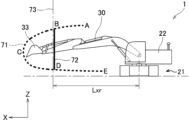
- FIG. 1 is a side view of a working machine according to a first embodiment of the present invention
- FIG. It is a circuit diagram of the working machine and the portable terminal.
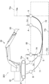
- FIG. 4 is a plan view showing a trajectory of the tip of the bucket associated with a designated operation in the working machine
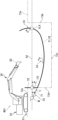
- FIG. 10 is a side view showing the trajectory of the tip of the bucket in the designated operation
- FIG. 4 is a side view showing a first position for determining tolerances on the work machine; It is a side view which shows the 2nd position for determining the said allowable range. It is a side view which shows the 3rd position for determining the said allowable range.
- FIG. 11 is a side view showing a fourth position for determining the allowable range;
- FIG. 4 is a plan view showing a trajectory of the tip of the bucket associated with a designated operation in the working machine
- FIG. 10 is a side view showing the trajectory of the tip of the bucket in the designated operation
- FIG. 4 is a side view showing a first position
- FIG. 5 is a side view showing the allowable range determined based on the first to fourth positions;
- FIG. 10 is a diagram showing the allowable range before the allowable range is updated;
- FIG. 4B is a side view showing the tolerance range after the tolerance range has been updated;
- FIG. 4 is a side view showing the dump truck bed and the lower boundary surface of the allowable range set thereabove;
- FIG. 14 is a side view showing an example in which two waypoints are set between the start point and end point of the excavation operation of the work machine according to the third embodiment;
- FIG. 5 is a side view showing an example in which a via point is set between the start point and the end point;
- FIG. 14 is a side view showing an example in which the same correction as the correction of the excavation operation according to the first embodiment is performed in the working machine according to the fourth embodiment;
- FIG. 11 is a side view showing an example of correction of excavation motion according to the fourth embodiment;
- FIG. 14 is a side view showing another example of excavation motion correction according to the fourth embodiment.
- Figure 15 is a side view showing the amount of excavation reduced by the correction shown in Figure 14;
- FIG. 11 is a side view showing a change in excavation depth to compensate for the reduced excavation volume; It is a flow chart which shows the processing performed by the control unit concerning the 4th embodiment.
- FIG. 14 is a side view showing correction of excavation performed in the work machine according to the fifth embodiment;
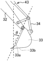
- FIG. 19 is a side view of the bucket of the work machine shown in FIG.
- FIG. 19 is a side view showing the trajectory of the tip of the bucket in an excavating operation before the correction shown in FIG. 18 is performed;
- FIG. 19 is a diagram showing the trajectory of the tip of the bucket due to the excavation operation after the correction shown in FIG. 18 has been performed;
- FIG. 14 is a side view showing an example in which a portion including the end point of the excavation operation is corrected in the working machine according to the fifth embodiment;
- FIG. 14 is a diagram showing an example in which a portion including the lowest point in the excavation operation is corrected in the work machine according to the fifth embodiment;
- FIG. 1 is a side view of a work machine 1 according to an embodiment of the invention.
- the work machine 1 is a hydraulic excavator, and includes a machine body 25 including a lower travel body 21 and an upper revolving body 22 , an attachment 30 , and a work drive device 40 .
- the lower traveling body 21 includes a pair of crawlers, and can travel on the ground by moving the pair of crawlers.
- the upper revolving body 22 is attached to the lower traveling body 21 via a revolving device 24 so as to be able to revolve.
- the turning device 24 is a turning driving device that turns the upper turning body 22 .
- the upper revolving body 22 includes a cab (cab) 23 located in its front portion.
- the attachment 30 is a work device, and is attached to the upper revolving body 22 so as to be able to perform work operations including vertical rotation.
- the attachment 30 includes a boom 31 , an arm 32 and a bucket 33 .
- the boom 31 has a base end attached to the upper revolving body 22 so as to be vertically rotatable (raising and lowering), and a tip end on the opposite side.
- the arm 32 has a base end attached to the tip of the boom 31 so as to be vertically rotatable with respect to the boom 31 and a tip on the opposite side.
- the bucket 33 is a tip attachment that is the tip of the attachment 30 and is attached to the tip of the arm 32 so as to be rotatable in the front-rear direction with respect to the arm 32 .
- the bucket 33 has a shape that enables excavation, leveling, scooping, and the like of an object to be excavated such as earth and sand.
- the object to be excavated is not limited to earth and sand, and may be stones or waste (industrial waste, etc.).
- the working machine according to the present invention is not limited to an excavating machine, and therefore the work object is not limited to an excavating object.
- the tip attachment that constitutes the tip of the working device according to the present invention is not limited to the bucket 33, and may be a grapple that grips, a lifting magnet that attracts, or the like.
- the work drive device 40 hydraulically moves the attachment 30 to perform the work operation.
- the work drive device 40 in this embodiment includes a plurality of hydraulic cylinders, each of which is extendable, including a boom cylinder 41 , an arm cylinder 42 and a bucket cylinder 43 .
- the boom cylinder 41 rotates the boom 31 with respect to the upper swing body 22 .
- the boom cylinder 41 has a base end rotatably connected to the upper rotating body 22 and a tip end rotatably connected to the boom 31 .
- the arm cylinder 42 rotates the arm 32 with respect to the boom 31 .
- the arm cylinder 42 has a base end rotatably connected to the boom 31 and a tip end rotatably connected to the arm 32 .
- the bucket cylinder 43 rotates the bucket 33 with respect to the arm 32 .
- the bucket cylinder 43 has a base end rotatably connected to the arm 32 and a tip end rotatably connected to the link member 34 .
- the link member 34 is rotatably connected to the bucket 33 and connects the bucket cylinder 43 and the bucket 33 to each other.
- the working machine 1 further includes a turning angle sensor 52 as a turning angle detector and a working attitude detector 60 .
- the turning angle sensor 52 detects the turning angle of the upper turning body 22 with respect to the lower traveling body 21 .
- the turning angle sensor 52 is, for example, an encoder, resolver, or gyro sensor.
- the turning angle of the upper turning body 22 when the front of the upper turning body 22 coincides with the front of the lower traveling body 21 is 0°.
- the working posture detector 60 detects the working posture, which is the posture of the attachment 30, which is the working device.
- the working posture detector 60 includes a boom tilt angle sensor 61, an arm tilt angle sensor 62, and a bucket tilt angle sensor 63 in this embodiment.
- the boom tilt angle sensor 61 is attached to the boom 31 and detects the attitude of the boom 31 .
- the boom tilt angle sensor 61 acquires the tilt angle of the boom 31 with respect to the horizontal line.
- the boom tilt angle sensor 61 is, for example, a tilt (acceleration) sensor.
- the attitude detector 60 may include a rotation angle sensor for detecting the rotation angle of the boom 31 around the boom foot pin or a stroke sensor for detecting the stroke of the boom cylinder 41 instead of the boom tilt angle sensor 61. good.
- the arm tilt angle sensor 62 is attached to the arm 32 and detects the posture of the arm 32 .
- the arm tilt angle sensor 62 acquires the tilt angle of the arm 32 with respect to the horizontal line.
- the arm tilt angle sensor 62 is, for example, a tilt (acceleration) sensor.
- the working posture detector 60 includes a rotation angle sensor for detecting the rotation angle of the arm 32 about the arm connecting pin or a stroke sensor for detecting the stroke of the arm cylinder 42 instead of the arm tilt angle sensor 62. It's okay.
- the bucket tilt angle sensor 63 is attached to the link member 34 and detects the attitude of the bucket 33 .
- the bucket tilt angle sensor 63 acquires the tilt angle of the bucket 33 with respect to the horizontal.
- the bucket tilt angle sensor is, for example, a tilt (acceleration) sensor.
- the working posture detector 60 includes a rotation angle sensor for detecting the rotation angle of the bucket 33 about the bucket connecting pin or a stroke sensor for detecting the stroke of the bucket cylinder 43 instead of the bucket inclination angle sensor 63. It's okay.
- the work machine 1 further includes a GNSS (Global Navigation Satellite System) sensor 26 .
- the GNSS sensor 26 is a GPS sensor or the like, is provided on the upper swing body 22, and detects the coordinates of the position of the upper swing body 22 within the work site.
- the GNSS sensor 26 may be provided on the undercarriage 21 or the attachment 30 .
- the GNSS sensor 26 is a positioning sensor, and acquires the coordinates of the position of the work machine 1 (upper swing body 22) in the global coordinate system.
- the position detection device is not limited to the GNSS sensor 26, and may be a ranging sensor such as a total station.
- the work machine 1 further includes a LiDAR (Light Detection and Ranging or Laser Imaging Detection and Ranging) 27 .
- the LiRAR 27 is provided on the upper rotating body 22, but may be provided on the attachment 30 (for example, the boom 31).
- the LiDAR 27 is an acquisition device that acquires the surrounding conditions of the work site. Specifically, the LiDAR 27 acquires point cloud data indicating the distance from the position where the LiDAR 27 is attached to an object (dump truck or obstacle) in the work site.
- the acquisition device is not limited to the LiDAR 27, and may be a stereo camera or a TOF (Time Of Flight) sensor.
- the working machine 1 can communicate with the mobile terminal 3 shown in FIGS. 1 and 2.
- the mobile terminal 3 is a terminal, such as a tablet terminal, that is carried and operated by a worker at the work site.
- a worker who operates the mobile terminal 3 is, for example, a person who manages the work machine 1 .
- the mobile terminal 3 may be a smart phone or the like.
- FIG. 2 is a circuit diagram of the working machine 1 and the mobile terminal 3.
- the working machine 1 includes a control unit 11 , a working machine-side communication device 12 and a storage device 13 .
- the mobile terminal 3 includes a mobile terminal side control unit 15 , a mobile terminal side communication device 16 and a display 17 .
- the turning angle information is information acquired by the turning angle sensor 52 , that is, information about the turning angle (attitude) of the upper turning body 22 with respect to the lower traveling body 21 .
- the working attitude information is information about the working attitude of the attachment 30, and includes information about the attitude of the boom 31 acquired by the boom inclination angle sensor 61 and the arm information acquired by the arm inclination angle sensor 62. 32 and information about the attitude of the bucket 33 acquired by the bucket tilt angle sensor 63 .
- the coordinates of the position of the upper swing body 22 in the work site detected by the GNSS sensor 26 are input to the control unit 11 . Further, the control unit 11 receives information about the surrounding conditions of the work site acquired by the LiDAR 27 .
- the control unit 11 automatically controls the operation of the work machine 1. Specifically, the control unit 11 causes the upper rotating body 22 and the attachment 30 to perform a designated operation specified in advance, in this embodiment, a series of operations from excavating earth and sand to dumping soil. It can function as control means for controlling the driving of the upper rotating body 22 and the attachment 30 .
- the working machine 1 can thus be automatically operated.
- the control unit 11 automatically operates the swing device 24 and the work drive device 40 based on information detected by the swing angle sensor 52 and the work posture detector 60, respectively.
- the storage device 13 stores the specified action.
- the specified operation includes a series of operations in this embodiment, and is specified by teaching by the operator.
- the tip portion of the attachment 30, which is the tip of the bucket 33 in this embodiment draws a predetermined trajectory.
- the work machine side communication device 12 can communicate with the mobile terminal side communication device 16 of the mobile terminal 3 .
- FIGS. 3 and 4 are respectively a plan view and a side view showing the trajectory of the tip of the attachment 30 (the tip of the bucket 33 in this embodiment) in the series of operations.
- the tip of the bucket 33 rotates together with the upper rotating body 22 from point A to point C via point B shown in FIGS. After that, the tip of the bucket 33 moves from the point C to the point E via the point D toward the upper revolving body 22 .
- the trajectory of the tip of the bucket 33 designated by teaching is indicated by a dotted line.
- the control unit 11 controls the driving of the upper swing body 22 and the attachment 30 so that the tip of the bucket 33 passes through the points A to E, which are a plurality of target points, in order.
- the body 22 and the attachment 30 are caused to perform the series of motions.
- the point B and the point D are a distance Lx ( For example, it is set at a position separated by 6000 mm).
- the point C is set at a position separated from the turning center axis 20 of the upper turning body 22 in the X direction by a distance (for example, 7000 mm) larger than the distance Lx.
- the control unit 11 also functions as setting means for setting a permissible range of operation of the attachment 30 in order to prevent interference between the obstacles and the like and the attachment 30 .
- the control unit 11 sets the allowable range based on information such as the obstacles at the work site.
- the front boundary surface 73 of the allowable range is indicated by a dashed line.
- the allowable range may be set in a coordinate system based on the work machine 1, such as a machine coordinate system with the center of rotation of the upper rotating body 22 as an origin, or in a coordinate system based on the work site. For example, it may be set in a global coordinate system.
- the inner side (the The range on the side closer to the turning center axis 20; the range on the right side of the front boundary surface 73 indicated by the dashed line in FIGS. 3 and 4) is set as the allowable range.
- the point C is out of the allowable range.
- the control unit 11 determines that the restriction target portion of the attachment 30, which is the tip of the bucket 33 in this embodiment, exceeds the allowable range (Fig. 4, the tip of the bucket 33 protrudes forward beyond the front boundary surface 73), the designated operation is performed so that the tip of the bucket 33 does not exceed the allowable range (set inside the front boundary surface 73). to correct.
- the restriction target portion which is the portion of the attachment 30 that is prohibited from deviating from the allowable range, is the tip of the bucket 33, but the restriction target portion is limited to the tip of the bucket 33. can be set arbitrarily.
- the control unit 11 sets the positions of the points B, C, and D to a distance (for example, 5900 mm) that is smaller than the distance Lx from the turning center axis 20 in the X direction. Change to the position where By correcting the designated operation in this way, the trajectory 71 of the tip of the bucket 33 from the point B to the point D via the point C is changed to the trajectory shown by solid lines in FIGS. 72, i.e., the locus along the front boundary surface 73 at a position on or behind the front boundary surface 73 indicated by the dashed line in FIGS. 3 and 4 (right side in FIGS. 3 and 4). be done. In this way, deviation of the tip of the bucket 33 outside the front boundary surface 73 is restricted. This eliminates the need for the operator to re-designate the designated operation by teaching in order to prevent the tip of the bucket 33 from exceeding the allowable range, thereby reducing the burden on the operator.
- a distance for example, 5900 mm
- the control unit 11 controls the specified operation so that the portion of the attachment 30 other than the tip of the bucket 33 does not exceed the allowable range even if the portion of the attachment 30 exceeds the allowable range in at least a part of the specified operation. may be corrected. That is, the restriction target portion of the attachment 30 may be an appropriately set portion other than the tip of the bucket 33 .
- the tip of the arm 32 may be the farthest portion from the upper swing body 22 .
- the tip of the boom 31 may be the furthest part from the upper rotating body 22 . In this way, even if the tip of the arm 32 or the tip of the boom 31 exceeds the allowable range, the specified operation is corrected so that the tip does not exceed the allowable range. is prevented from being exceeded.
- the allowable range is set based on a plurality of possible positions of the tip of the bucket 33, which is the restriction target portion of the attachment 30.
- FIG. This setting is effective in a site where the allowable range cannot be clearly determined or in a site where the surrounding environment of the work machine 1 changes.
- the restriction target portion of the attachment 30 is not limited to the tip of the bucket 33, and may be the tip of the arm 32, for example.
- the tip of the bucket 33 is positioned at the first position shown in FIG. Stored in the control unit 11 .
- the first position defines the upper end of the tolerance to be set.
- the tip of the bucket 33 is positioned at the second position shown in FIG. 5B and the second position is stored in the control unit 11 .
- the second position defines the lower end of the allowable range.
- the tip of the bucket 33 is positioned at the third position shown in FIG. 5C and the third position is stored in the control unit 11 .
- the third position defines the front end of the tolerance range.
- the tip of the bucket 33 is positioned at the fourth position shown in FIG. 5D and the fourth position is stored in the control unit 11 .
- the fourth position defines the trailing edge of the tolerance.
- the control unit 11 sets the allowable range Ra as shown in FIG. 5D.
- Such setting of the allowable range Ra may be performed in a coordinate system (machine coordinate system) based on the work machine 1, or in a coordinate system (for example, a global coordinate system) based on the work site. may be done.
- the allowable range Ra can be easily set. Moreover, even in a site where the environment around the working machine 1 changes, the allowable range Ra can be flexibly set.
- the permissible range Ra shown in FIG. 5D is set in front of the working machine 1, but not only in front of the working machine 1 but also behind the working machine 1, for example, as shown in FIG.
- a permissible range Rb may be set.
- the allowable range Ra set in front of the work machine 1 is applied when the swing angle of the upper swing body 22 is in the range of -90° to 90° with 0° interposed therebetween.
- the allowable range Rb set to the rear is applied when the swing angle of the upper swing body 22 is in the range of -90° to 90° with 180° (-180°) interposed therebetween.
- the permissible range Rb shown in FIG. 6 is set only above the upper rotating body 22 in order to avoid obstacles behind the work machine 1, but is not limited to this.
- the control unit 11 shown in FIG. 2 transmits to the mobile terminal 3 that the control unit 11 itself corrects the specified action, that is, the series of actions, and the mobile terminal side control unit 15 of the mobile terminal 3 shall notify the amendment.
- the control unit 11 and the mobile terminal side control unit 15 constitute notification means.
- the mobile terminal-side control unit 15 causes the display 17 of the mobile terminal 3 to display information about the correction, and the speaker of the mobile terminal 3 notifies about the correction. output a sound for, and/or The notification can notify the operator who manages the work machine 1 that the specified motion will be corrected.
- control unit 11 may be difficult for the control unit 11 to cause the upper revolving body 22 and the attachment 30 to perform the specified motion corrected by the control unit 11 .
- the control unit 11 is preferably configured to function as stop control means for stopping the operations of the upper rotating body 22 and the attachment 30 . As a result, it is possible to prevent the upper rotating body 22 and the attachment 30 from making unreasonable movements.
- the allowable range When the allowable range is set in a coordinate system (machine coordinate system) based on the work machine 1, it moves following the movement of the lower traveling body 21 of the work machine 1 in the traveling direction.
- a coordinate system for example, a global coordinate system
- the allowable range for the work machine 1 moves along with the movement of the work machine 1 in the traveling direction. relative position changes.
- the control unit 11 controls the position of the upper rotating body 22 detected by the GNSS sensor 26, that is, the position in the coordinate system when the allowable range is set in the coordinate system based on the work site. , the allowable range is updated as the work machine 1 moves.
- the allowable range shown in FIG. 4 that is, the allowable range from the turning center axis 20 to the position separated by the distance Lx (for example, 6000 mm) to the left (X direction) of the lower traveling body 21 is the work site.
- the control unit 11 moves the turning center axis
- the allowable range is updated so that the distance from 20 to the outer edge of the allowable range (the left end in FIG. 7) is reduced to a distance Lxr (for example, 5000 mm) smaller than the distance Lx before updating.
- the update of the allowable range accompanying the movement of the work machine 1 in this manner is performed by adjusting the relative positions of the attachment 30 and the like and the allowable range regardless of the movement of the work machine 1 in the coordinate system based on the work site. Allows relationships to be properly determined. This eliminates the need for the operator to reset the allowable range after the work machine 1 is moved, thereby reducing the burden on the operator.
- the mobile terminal side communication device 16 of the mobile terminal 3 shown in FIG. 2 can communicate with the working machine side communication device 12 of the working machine 1 .
- the mobile terminal-side control unit 15 of the mobile terminal 3 acquires locus information and allowable range information from the work machine 1 through the mobile terminal-side communication device 16 .
- the trajectory information includes information about the trajectory 71 drawn by the tip of the bucket 33 accompanying the specified motion, and information about the trajectory 72 of the tip of the bucket 33 after being changed by correction of the specified motion. include.
- the permissible range information includes information about the permissible range set as described above and information about the relative positions of the upper rotating body 22 and the attachment 30 with respect to the permissible range.
- the control unit 11 and the mobile terminal side control unit 15 display information about the specified motion and information about the result of correction of the specified motion by the control unit 11 on the display 17, which is a motion information display device. It functions as an operation display control means for causing the Specifically, trajectories indicated by dotted lines and solid lines in FIGS. 3 and 4, respectively, that is, a trajectory 71 drawn by the tip of the bucket 33 accompanying the specified motion before correction, and a specified motion after correction. A trajectory 72 drawn by the tip of the bucket 33 as it moves is displayed on the display 17 .
- the display on the display 17 allows the operator to compare the trajectories 71 and 72 before and after the correction to accurately grasp the post-correction movement of the upper rotating body 22 and the attachment 30. It is possible to change the conditions for correction or reset the designated operation when there is a problem with subsequent movement.
- control unit 11 and the mobile terminal side control unit 15 display the set allowable range and the relative positions of the upper rotating body 22 and the attachment 30 with respect to the allowable range on a display serving as a position information display device. 17.
- the display 17 displays a front boundary surface 73 of the allowable range and graphics representing the upper swing body 22 and the attachment 30, respectively.
- the display provided by the display 17 enables the operator to easily grasp the relative positions of the upper rotating body 22 and the attachment 30 with respect to the allowable range (for example, the front boundary surface 73), and furthermore , it is possible to take measures such as moving the working machine 1 when there is a problem with the relative position.
- the permissible range is set based on a plurality of positions where the tip of the bucket 33, which is the restriction target portion of the attachment 30, can be positioned.
- the control unit 11 which is the setting means according to the second embodiment, sets the permissible range based on the information about the surrounding conditions input from the management device 4 shown in FIG.
- the management device 4 manages the surrounding conditions of the work site, and is, for example, a management server.
- the management device 4 manages information on the positions of obstacles, passages, and the like in the work site.
- the work machine side communication device 12 of the work machine 101 shown in FIG. 2 can communicate with the management device 4 .
- the control unit 11 acquires the surrounding conditions of the work site managed by the management device 4 from the management device 4 .
- the operator of the work machine 101 does not need to perform an operation for setting the allowable range. Therefore, the allowable range can be easily set.
- control unit 11 which is the setting means of the work machine 101 according to the second embodiment, sets the allowable range based on the ambient conditions of the work site acquired by the LiDAR 27 shown in FIG.
- FIG. 9 is a side view showing the loading platform 6 of the dump truck 5 and its surroundings, exemplifying the work of dumping earth and sand onto the loading platform 6. As shown in FIG. The setting of the allowable range can also be applied to the work of leveling the earth and sand loaded on the loading platform 6 with the bucket 33 .
- the amount of earth and sand loaded on the loading platform 6 increases with the number of times of earth removal work on the loading platform 6 .
- the surrounding conditions around the loading platform 6 acquired by the LiDAR 27 change from moment to moment.
- the tip of the bucket 33 moves from the left side to the right side in the figure while drawing a trajectory 71 indicated by a dotted line in FIG.
- the control unit 11 sets an allowable range above the earth and sand loaded on the loading platform 6 based on the surrounding conditions of the work site acquired by the LiDAR 27 .
- the lower boundary surface 73 of the allowable range is indicated by a dashed line.
- the side closer to the loading platform 6 than the lower boundary surface 73 (lower side in FIG. 9) is outside the allowable range, and the side farther from the loading platform 6 than the lower boundary surface 73 (upper side in FIG. 9). is the allowable range.
- the control unit 11 changes the allowable range (the lower boundary surface 73 of the allowable range) every moment in accordance with changes in the amount of earth and sand loaded on the loading platform 6 . In this way, it is possible to set an appropriate allowable range according to changes in the ambient conditions based on the acquired ambient conditions.
- the control unit 11 which is a correcting means, corrects the specified motion so that the tip of the bucket 33 draws a trajectory 72 indicated by a solid line in FIG.
- FIG. 10 Note that the description of the configuration common to the first embodiment and the effects produced thereby will be omitted, and mainly the differences from the first embodiment will be described.
- symbol as 1st Embodiment is attached
- point A and point B which are target points, are positioned near the front boundary surface (left boundary surface in FIG. 10) 73 of the allowable range indicated by the dashed line. is set.
- the point B is located below the point A and is closer to the front boundary surface 73 of the tolerance than the point A is. Also, the distance between the points A and B is greater than the distance between the points A and B in the first embodiment shown in FIG.
- the control unit 11 which is a control means of the work machine 201, controls the driving of the upper rotating body 22 and the attachment 30 so that the tip of the bucket 33 passes through the points A and B in this order.
- the upper rotating body 22 and the attachment 30 are caused to perform the specified operation.
- the path of the tip of the bucket 33 between the point A and the point B is not fixed, and therefore any path can be taken between the point A and the point B. Therefore, depending on the route, the tip of the bucket 33 may exceed the allowable range (in FIGS. 10 and 11, it may protrude to the left of the front boundary surface 73), as indicated by a locus 71 indicated by a dotted line.
- the control unit 11 controls the point A and the At least one via point is set at a position between the point B and within the allowable range (a position on the right side of the front boundary surface 73 in FIGS. 10 and 11).
- the at least one waypoint includes two waypoints C1 and C2 in the example shown in FIG. However, said at least one waypoint may comprise one or more waypoints.
- the control unit 11 sets the two waypoints C1 and C2 on the line L1 connecting the points A and B.
- the line L1 may be straight or curved.
- the line L1 exemplified in FIG. 10 is a straight line when viewed from the side of the upper revolving body 22 of the working machine 201, and also when viewed in a direction along the revolving axis of the upper revolving body 22 (work line). (even viewed from above the machine 201) is straight.
- the two waypoints C1 and C2 may be set at equal intervals in the X direction, which is the front-rear direction of the upper rotating body 22, or may be set at equal intervals in the Z direction, which is the vertical direction of the upper rotating body 22. Alternatively, they may be set at positions equally dividing the line L1 itself. Setting the two waypoints C1 and C2 on the line L1, which is a straight line connecting the point A and the point B as described above, can simplify the calculation operation for the setting. can.
- the control unit 11 functions as correction means for correcting the specified motion so that the tip of the bucket 33 passes through the waypoints C1 and C2.
- the correction is such that the tip of the bucket 33 exceeds the allowable range even when the point A and the point B are close to the allowable range front boundary surface 73), that is, the front boundary surface 73 is exceeded. to reliably prevent
- FIG. 11 shows a second example of setting of the waypoints by the control unit 11.
- the control unit 11 sets the via point C at a position between the two target points A and B and within the allowable range (inner side of the front boundary surface 73, right side in FIG. 11). do.
- the point B is the final point of the designated motion before correction, and is therefore the downstream target point of the two target points A and B.
- the waypoint C is set on a straight line L2 passing through the point B.
- the straight line L2 is a horizontal plane at an angle formed by the horizontal plane when the tip of the bucket 33 passes through the point B by the designated motion before correction and the movement direction of the attachment 30, that is, the moving direction of the tip of the bucket 33. is tilted with respect to
- the operation at point B is an excavation operation.
- the setting of the waypoint C as described above enables the attachment 30 to suitably perform the work (excavation work) by the designated operation at the point B. As shown in FIG.
- the via point C is located directly below the point A when viewed from the side of the upper revolving body 22, and when viewed in the direction along the central axis of revolving of the upper revolving body 22 (the above It is located between the point A and the point B (when the work machine 201 is viewed from above).
- the straight line L2 is the horizontal plane and the movement direction of the attachment 30 when the attachment 30 performs a predetermined work at the point B, more specifically, the movement direction of the restriction target portion (the tip of the bucket 33 in this embodiment). may be inclined with respect to the horizontal plane at an angle formed by
- the predetermined work at the point B is excavation work.
- the attachment 30 can be made to perform the predetermined work (excavation work) at the point B in a suitable manner.
- FIG. 12 to 17 a working machine 301 according to a fourth embodiment will be described with reference to FIGS. 12 to 17.
- FIG. Note that the description of the configuration common to the first embodiment and the effects produced thereby will be omitted, and mainly the differences from the first embodiment will be described.
- symbol as 1st Embodiment is attached
- the designated operation according to the fourth embodiment is an excavation operation for excavating earth and sand, which is an excavation target, with the bucket 33 of the work machine 301, and the excavation operation is corrected.
- the object to be excavated is not limited to earth and sand, and may be stones, wastes, or the like.
- the purpose of the excavation operation is to excavate earth and sand in an excavation range (rectangular range in FIG. 12) 80 surrounded by broken lines in FIG. It is set to the front (to the right in FIG. 12).
- the permissible range according to the fourth embodiment is defined by a plurality of boundary surfaces indicated by dashed lines in FIG. , a fourth boundary surface 73d and a fifth boundary surface 73e.
- the second boundary surface 73b is a vertical surface set at a position away from the work machine 301 in front of the lower traveling body 21, and the first boundary surface 73a extends further from the upper end of the second boundary surface 73b. It is a horizontal plane extending away from the work machine 401 .
- the start point A is the end point of the excavation operation, is at the same height as the soil surface, and is located in front of the second boundary surface 73b (that is, outside the allowable range).
- the third boundary surface 73c is a horizontal surface along the bottom surface of the excavation range 80 and has a front end and a rear end connected to the second and fourth boundary surfaces 73b and 73d, respectively.
- the fourth boundary surface 73d is a vertical surface that vertically crosses the earth and sand at a position forward of the front end of the lower traveling body 21 of the working machine 301 and is connected to the rear end of the third boundary surface 73c.
- the fifth boundary surface 73e is a horizontal surface along the ground on which the work machine 301 rests and is connected to the upper end of the fourth boundary surface 73d.
- the tip of the bucket 33 excavates along the trajectory 71 indicated by the dashed line in FIG. Exceeding tolerance. More specifically, the tip of the bucket 33 protrudes forward (to the right in FIG. 12) from the second boundary surface (front boundary surface) 73b.
- correction is performed to change the starting point A to a position on the second boundary surface 73b.
- the tip of the bucket 33 draws a locus 72 indicated by a solid line. In this trajectory 72 , the penetrating direction in which the bucket 33 penetrates into the earth and sand is substantially vertical, and it is difficult for the tip of the bucket 33 to follow the trajectory 72 .
- control unit 11 which is the correction means according to the fourth embodiment, is arranged so that the start point X in the excavation operation after correction is within the allowable range, as indicated by the solid line in FIG.
- the entire excavation range is shifted toward the work machine 301 (to the left in FIG. 13) so that it is positioned at the same height as the soil surface.
- the height of the power plane can be obtained, for example, by a LiDAR (Height Detector) 27 shown in FIG.
- the horizontal movement distance La from the start point A of the excavation motion before correction to the start point X of the excavation motion after correction, and the distance La from the end point B of the excavation motion before correction to the and the horizontal movement distance Lb to the end point Y of the excavation operation are equal to each other.
- the horizontal distance Lb from the end point B of the excavation operation before correction to the point C at the same height on the fourth boundary surface 73d is the start point of the excavation operation before the correction. Since it is larger than the horizontal distance La from A to point D at the same height on the second boundary surface (front boundary surface) 73b, it is assumed that the entire excavation range of the upper revolving body 22 is moved by the horizontal distance Lc. When it is shifted forward (to the right in FIG. 14), the start point X of the excavation operation after correction exceeds the allowable range, that is, the start point moves outside the second boundary surface 73b (to the right in FIG. 14). It will stick out.
- the entire range of the excavation operation is shifted by the distance La, which is smaller than the distance Lc, so that the start point X of the excavation operation after correction does not exceed the allowable range. Therefore, the start point X of the excavation operation after correction is changed to a point on the second boundary surface 73b.
- the point B' corresponding to the end point B before the shift cannot reach the fourth boundary surface 73d, and the allowable Since it is located outside the range (behind the fourth boundary surface 73d), the trajectory of the tip of the bucket 33 is shown in FIG. Corrections are made to alter the trajectory 74 shown.
- the shape of the portion of the trajectory 74 from the starting point X on the second boundary surface 73b to the via point E on the third boundary surface 74d is the same as the trajectory 71 before correction. From E to the end point Y, the trajectory is such that the tip of the bucket 33 rises substantially vertically. Therefore, the waypoint E is the vertical boundary surface closer to the working machine 301 of the boundary surfaces defining the allowable range, that is, the fourth boundary surface 73d, and the trajectory 71 of the bucket 33 before correction. It is the point of intersection with the trajectory 72 obtained by shifting forward by the distance La.
- the end point Y in the trajectory 74 is located on the front side of the end point B' in the trajectory 72 before the change, so the trajectory 72 before the change is In comparison, the excavated amount of earth and sand is reduced by the area S1 of the shaded area in FIG. .
- the control unit 11 selects a further trajectory to increase the excavation depth to compensate for the reduced amount of excavation. is preferably arranged to change the
- FIG. 16 shows a specific example of the further trajectory change.
- the trajectory 74 shown in FIG. 15 is changed to a lower trajectory 75 .
- the lowest point D is the lowest point among the points included in the locus 74 . If the trajectory 74 includes multiple lowest points, any of the lowest points is selected.
- the lowest point D is changed to a point F directly below it (lowest point after change), and the way point E is a point directly below it (on the fourth boundary surface 73d).
- the waypoint is changed to G.
- the trajectory 75 is a curved portion connecting the final common point H, the lowest point D and the intermediate point E shown in FIG.
- the final common point H is the most downstream point of the portion of the locus 75 common to the locus 74 .
- Such modification is sandwiched between the curve portion before modification (the curve portion connecting points H, D, and E) and the curve portion after modification (the curve portion connecting points H, F, and G). It is possible to supplement the excavation amount by the area of the region (the area S2 of the hatched region in FIG. 16). The lowest point F after the change and the lowest point F after the change and When the waypoint G is set, the excavation amount reduced by the correction shown in FIG. 15 is completely compensated by the further correction shown in FIG.
- the final common point H is obtained by reducing the step of the corrected trajectory 75 caused by changing the lowest point D and the waypoint E to the changed lowest point F and the waypoint G after change. It is set so as to ensure smooth movement of the bucket 33 .
- the final common point H is set at a position upstream of the lowest point D by a distance Lh on the locus 74, and the final common point H and the changed lowest point F are connected by straight lines, the trajectory 75 after the further correction is specified. Setting the final common point H such that the difference between the slope of the straight line and the slope of the tangent line of the locus 74 at the final common point H is small, preferably both slopes are equal, is the locus 75. allows to smooth out the
- the post-change lowest point F is set at a height equal to or higher than the second boundary surface 73b, which is the lower boundary surface of the allowable range. need to Therefore, compensation for the excavation amount due to the downward change from the lowest point D to the post-change lowest point F is performed within the allowable range inside the third boundary surface 73c.
- FIG. 17 is a flow chart showing processing performed by the control unit 11 for correction according to the fourth embodiment.
- the control unit 11 determines whether or not at least one of the two end points (start point A and end point B) of the excavation operation before correction is outside the allowable range. It is determined whether or not there is deviation in the direction (step S1). Only when it is determined that at least one of the end points of the excavation motion before correction is outside the allowable range (YES in step S1), the control unit 11 causes the at least one end point to fall within the allowable range. (step S2). For example, if the trajectory before correction is a trajectory 71 whose end point B greatly deviates from the allowable range as shown in FIG. In the same figure, it is moved in the horizontal direction by a horizontal distance La) and shifted to the locus 72 .
- step S1 If it is determined that all of the end points of the excavation motion before correction are within the allowable range (NO in step S1), horizontal movement of the range of the excavation motion is not necessary, so step S2 and the steps related thereto will be described later. , steps S3 to S6 are omitted.
- control unit 11 determines whether or not the end point of the horizontally moved excavation operation is still outside the allowable range (step S3). For example, in the example shown in FIG. 14, it is determined whether the point B' after the horizontal movement of the end point B is still outside the allowable range.
- step S3 When it is determined that the end point is outside the allowable range (YES in step S3), the control unit 11 adjusts the trajectory so that the end point outside the allowable range is within the allowable range. Correct (step S4). For example, when the end point B' after the movement is outside the allowable range as shown in FIG. 14 and 15, the trajectory 72 is changed to a trajectory 74 that rises substantially vertically from the via point E to the end point Y. FIG.
- control unit 11 determines whether or not the amount of excavation will decrease as the trajectory is corrected (step S5). Only when it is determined that the excavation amount will decrease (YES in step S5), the control unit 11 further corrects the trajectory so as to compensate for the decreased excavation amount (step S6). For example, when the excavation amount decreases by an area S1 as shown in FIGS. The trajectory 74 passing through the point E is changed downward to the trajectory 75 passing through the lowest point F after change and the intermediate point G after change.
- the control unit 11 determines whether or not the lowest point of the trajectory of the tip of the bucket 33 is outside the allowable range (step S7). Only when it is determined in step S7 that the lowest point is outside the allowable range (YES in step S7), the control unit 11 corrects the lowest point (step S8). For example, if the lowest point F shown in FIG. 16 is below the third boundary surface 73c of the allowable range, the lowest point F is adjusted to fall within the allowable range. Correct the lower point F upward.
- the control unit 11 controls the drive of the attachment 30 so as to cause the attachment 30 to perform the excavation operation, which is the designated operation finally determined through the processing of steps S1 to S8 described above (step S9 ).
- FIG. Note that the description of the configuration common to the first embodiment and the effects produced thereby will be omitted, and mainly the differences from the first embodiment will be described.
- symbol as 1st Embodiment is attached
- the excavation operation of excavating earth and sand with the bucket 33 is corrected.
- the series of motions which are designated motions in the fifth embodiment, include an excavation motion of excavating earth and sand with the bucket 33 .
- the height of the soil surface is detected by the LiDAR (height detector) 27 shown in FIG.
- a tolerance defined by a plurality of boundary surfaces indicated by dashed lines is set for excavating earth and sand having a soil surface 82 indicated by dashed lines.
- the plurality of boundary surfaces include a first boundary surface 73a, a second boundary surface 73b, a third boundary surface 73c, and a fourth boundary similar to the first to fifth boundary surfaces 73a to 73e shown in It includes a surface 73d and a fifth boundary surface 73e.
- the starting point A of the excavation operation is the intersection of the trajectory 71 of the movement of the tip of the bucket 33 by the excavation operation and the soil surface 82, and in the example shown in FIG. It is located on the front side of the surface 73 a , that is, outside the allowable range, and is located at the same height as the soil surface 82 . That is, at the starting point A, the tip of the bucket 33 exceeds the allowable range.
- correction for moving the starting point A to a position on the second boundary surface 73b, which is the front boundary surface of the allowable range, in the same manner as in the first embodiment, in order to keep the tip of the bucket 33 within the allowable range. is performed, the trajectory 71 of the tip of the bucket 33 is changed to a trajectory 72, and the portion of the trajectory 71 that exceeded the allowable range as shown by the broken line is the second boundary as shown by the solid line. It becomes a surface along the surface 73b, and the start point X after correction is positioned on the second boundary surface 73b.
- correction of the digging motion involves changing the trajectory of the tip of the bucket 33, thereby changing the ground angle ⁇ of the bucket 33 at least during the beginning portion of the digging motion.
- the ground angle ⁇ is the angle formed by the upper surface 33a of the bucket 33 with respect to the vertical plane, as shown in FIG. Therefore, the ground angle ⁇ is 0° when the upper surface 33a faces the vertical direction.
- the control unit 11 which is the correcting means according to the fifth embodiment, corrects the excavation operation based on the set angle ⁇ s, which is the ground angle ⁇ of the bucket 33 set in advance. to set the ground angle ⁇ c of the bucket 33 after correction.
- the set angle ⁇ s that is, the ground angle of the bucket 33 set in advance is the ground angle set by teaching, numerical input, or the like.
- the control unit 11 adjusts the ground angle ⁇ of the bucket 33 when the bucket 33 penetrates into earth and sand that is an excavation object (work object) by the excavation operation before correction.
- the ground angle ⁇ of the bucket 33 when the bucket 33 is penetrated is set.
- the ground angle ⁇ of the bucket 33 when the bucket 33 penetrates earth and sand is the ground angle of the bucket 33 at the start points A and X of the excavation operation before and after correction.
- the control unit 11 determines the ground angle ⁇ of the bucket 33 when the bucket 33 is extracted from the earth and sand, and the ground angle ⁇ of the bucket 33 when the bucket 33 is extracted from the earth and sand by the excavation operation before correction.
- Set to ⁇ The ground angle ⁇ of the bucket 33 when the bucket 33 is pulled out of the earth and sand is the ground angle ⁇ of the bucket 33 at the end points B and Y of the excavation operation before and after the correction. In the example shown in FIG. 18, the end points B and Y before the correction and after the correction match each other.
- the control unit 11 further controls the ground angles ⁇ a and ⁇ b of the bucket 33 at the start point A and the end point B of the excavation operation before correction, and the excavation operation before correction.
- the ground angle ⁇ of the bucket 33 in the corrected excavation operation is set based on the path lengths of the trajectories 71 and 72 of the tip of the bucket 33 in each of the corrected excavation operations.
- the entire excavation operation that is, the entire range between the start point X and the end point Y, is targeted. Part of the range between and Y may be of interest.
- FIG. 20A shows a trajectory 71 of the tip of the bucket 33 in the excavation motion before correction
- FIG. 20B shows a trajectory 72 of the tip of the bucket 33 in the excavation motion after correction
- the ground angle ⁇ a of the bucket 33 at the start point A of the excavation motion before correction and the ground angle ⁇ x of the bucket 33 at the start point X of the excavation motion after correction are equal to each other.
- the ground angle ⁇ b of the bucket 33 and the ground angle ⁇ y of the bucket 33 at the end point Y of the excavation operation after correction are also equal to each other.
- the path length Lab of the locus 71 of the tip of the bucket 33 before correction is changed to the path length Lxy of the locus 72 of the tip of the bucket 33 after correction.
- the control unit 11 adjusts the ground angle ⁇ z of the bucket 33 at any position between the start point X and the end point Y on the trajectory 72 from the start point A on the trajectory 71 before correction to the above It is obtained by the following formula (1) based on the path length Lac to an arbitrary position.
- an arbitrary position on the locus 72 corresponds to an arbitrary position between the start point A and the end point B on the locus 71 .
- ⁇ z ⁇ x+( ⁇ y ⁇ x) ⁇ (Lac/Lab) ⁇ Lxy (1)
- the ground angle ⁇ z of the bucket 33 based on the above equation (1) is set so that when the ground angle ⁇ of the bucket 33 before correction is appropriate, the ground angle of the bucket 33 after correction is also appropriate. enable. This suppresses an increase in excavation resistance due to a change in the trajectory of the tip of the bucket 33 due to the correction of the excavation operation, and enables the earth and sand to be excavated appropriately.
- the above formula (2) includes the horizontal distances Dab, Dxy, and Dac.
- the horizontal distance Dab is the horizontal distance between the start point A and the end point B in the excavation operation before correction
- the horizontal distance Dxy is the start point X and the end point in the excavation operation after correction
- Y and the horizontal distance Dac is the horizontal distance between the start point A and the arbitrary position on the trajectory 71 .
- the setting of the ground angle ⁇ z of the bucket 33 based on the formula (2) also enables the ground angle of the bucket 33 after correction to be appropriate when the ground angle of the bucket 33 before correction is appropriate. .
- the distance from the start point X to the above-mentioned is set based on the above formula (1) or the formula (2), while the ground angle from the via point D to the end point Y is the ground angle before correction. may be set. Further, the ground angle ⁇ from the start point X to the waypoint D may be maintained at the ground angle ⁇ x at the start point X.
- FIG. 21 shows a case where earth and sand having a soil surface 82 indicated by a dotted line is excavated by the work machine 401, and the allowable range is set similarly to the first to fifth boundary surfaces 73a to 73e shown in FIG.
- a fourth boundary surface 73d which is a vertical surface closer to the work machine 401, is further away from the work machine 401 than the end point B of the excavation operation included in the specified operation. position, in other words, the end point B is positioned behind the fourth boundary surface 73d (on the left side in FIG. 21), that is, outside the allowable range.
- the end point B is positioned at the same height as the soil surface 82 . In this case, when the excavation operation is performed to move the tip of the bucket 33 along the trajectory having the end point B, that is, the trajectory 71 including the portion indicated by the broken line in FIG. exceeds the allowable range.
- the end point B is changed to the end point Y located on the fourth boundary surface 73d as in the first embodiment, and the trajectory 71 is changed as indicated by the solid line.
- the ground angle of the bucket 33 changes at least in a portion including the end point Y in the excavation operation. Even in this correction, the starting point A before the correction and the starting point X after the correction are the same.
- FIG. 22 shows a third boundary surface 73c which is the lower boundary surface among the first to fifth boundary surfaces 73a to 73e that define the allowable range in the same manner as the first to fifth boundary surfaces 73a to 73e shown in FIG. is above the lowest point on the trajectory 71 of the movement of the tip of the bucket 33 in the excavating motion included in the specified motion, in other words, the lowest point exceeds the third boundary surface 73c If it is located outside (below) it, it indicates . In this case, when the excavation operation is performed along the locus 71 including the lowest point as indicated by the dashed line, the tip of the bucket 33 exceeds the allowable range at the lowest point and the area before and after the lowest point.
- the lowest point is moved upward to a point on the third boundary surface 73c, and the portions before and after the lowest point are moved along the third boundary surface 73c.
- the bucket 33 is not ground-to-ground in a portion including at least the lowest point (horizontal portion along the third boundary surface 73c) of the excavation operation.
- the angle ⁇ changes. Such a change in the ground angle .theta. increases the excavation resistance and may prevent good excavation of earth and sand.
- the control unit 11 which is a correction means, adjusts the ground angle of the bucket 33 at the lowest point on the locus 72 so that the bottom surface 33b (see FIG. 19) of the bucket 33 becomes horizontal. set to an angle less than the ground angle.
- the lowest points on the locus 72 are all points on the locus 72 between the two waypoints E and F shown in FIG.
- the two waypoints E and F are the intersections of the locus 71 before correction and the third boundary surface 73c, and the portion between the two waypoints E and F is along the third boundary surface 73c. It is the part that extends horizontally across the
- the ground angle ⁇ of the bucket 33 at the lowest point on the locus 72 is set to an angle equal to or less than the ground angle at which the bottom surface 33b is horizontal. Allows it to be mined.
- a work machine that can perform automatic operation within the allowable range without increasing the burden on the worker.
- the work machine includes a lower traveling body, an upper revolving body, a working device, and a controller.
- the upper revolving body is rotatably mounted on the lower traveling body.
- the working device is attached to the upper revolving body so as to be able to perform a working operation.
- the controller controls the driving of the upper rotating body and the attachment so as to cause the upper rotating body and the attachment to perform a predetermined operation.
- the controller is configured to correct the specified motion so that the working device does not exceed a preset allowable range when a restriction target portion of the working device exceeds a preset allowable range during the specified motion.
- the controller corrects the specified motion to prevent the restricted target portion from exceeding the allowable range when the restricted target portion exceeds or is likely to exceed the allowable range during the specified motion. , the operator does not need to reset the designated operation by teaching or the like, thereby reducing the burden on the operator.
- the allowable range may be determined in advance and stored in the controller, or the controller may be configured to set the allowable range. In the latter case, it is preferable that the controller is configured to set the allowable range based on a plurality of possible positions of the specific portion of the working device. This makes it possible to easily set the allowable range by locating the specific parts at the plurality of positions. For example, even in a site where the allowable range cannot be clearly determined, the allowable range can be easily set. Moreover, the allowable range can be flexibly set even in a site where the environment around the work machine changes.
- the controller is configured to set the allowable range based on information about the surrounding conditions of the work site. This reduces the operator's burden of performing an operation for setting the allowable range, and enables the allowable range to be easily set.
- the controller is preferably configured to set the allowable range based on the ambient conditions managed by a management device that monitors the ambient conditions of the work site. This enables the allowable range to be easily set by effectively using the information managed by the management device.
- the work machine further includes an acquisition device that acquires information about the surrounding conditions of the work site, and the controller is configured to set the allowable range based on the surrounding conditions acquired by the acquisition device. good too. This makes it possible to set the allowable range according to the change even though the surrounding situation changes from moment to moment.
- the controller causes the upper rotating body and the working device to perform the designated operation by controlling driving of the upper rotating body and the working device such that the restriction target portion passes through a plurality of target points in order.
- the restriction target portion of the working device may exceed the allowable range between two target points selected from the plurality of target points in the specified motion before the correction, the two targets It is preferable that a waypoint is set between the points and within the allowable range, and the specified motion is corrected so that the restriction target part passes through the waypoint.
- the controller controls the distance between the two target points and By setting the waypoint located within the allowable range and correcting the specified motion so that the restriction target part passes through the waypoint, the restriction target part is prevented from exceeding the allowable range. can.
- the controller can easily set the waypoint by setting the waypoint on the line L1 connecting the two target points.
- the controller may be configured to set the waypoint on a straight line passing through the downstream target point.
- the downstream target point is a target point on the downstream side of the designated motion before the correction among the two target points, and the straight line indicates that the restriction target portion is the target point on the downstream side due to the specified motion before the correction. It is a straight line that is inclined with respect to the horizontal plane at an angle formed by the horizontal plane passing through the point and the direction of movement of the working device. Setting the waypoints on such a straight line enables the working device to preferably perform the designated operation at the downstream target point.
- the straight line is a straight line that is inclined with respect to the horizontal plane at an angle formed by the horizontal plane when the working device performs a predetermined work operation and the movement direction of the working device, more specifically, the moving direction of the restriction target portion. There may be. Setting the waypoints on such a straight line enables the working device to preferably perform the predetermined work at the downstream target point.
- the work machine is configured to control the height of the surface of the excavation target object. and the controller determines that at least one of the start point and the end point of the excavation motion before the correction is at a height equivalent to the height of the surface and is within the allowable range. If the end point is located outside the excavation motion, the end point in the excavation motion after the correction is horizontally moved within the allowable range at a height equivalent to the height of the surface. It is preferably configured to allow Such a correction that horizontally moves the range in which the excavation operation is performed makes it possible to maintain the movement of the bucket before the correction and ensure a smooth excavation operation.
- the controller increases the excavation depth so as to compensate for the decreased amount of excavation. It is preferably arranged to compensate for motion.
- the correction compensates for the decreased excavation amount by increasing the excavation depth, that is, the depth at which the object is excavated by the bucket, thereby suppressing a decrease in work efficiency due to the correction. .
- the controller is configured to correct the trajectory of the bucket in a direction to smooth the trajectory as the excavation depth is increased.
- the correction can suppress obstruction of the smooth movement of the bucket due to, for example, the occurrence of steps in the trajectory of the bucket due to the increase in the excavation depth.
- the controller is configured to set the ground angle of the bucket in the excavation operation after the correction based on a preset angle of the bucket. This enables good excavation by suppressing an increase in excavation resistance due to a change in the ground angle of the bucket, regardless of the change in the trajectory of the tip of the bucket due to the correction of the excavation operation.
- the controller adjusts the ground angle of the bucket when it penetrates the excavation object in the excavation operation after the correction to the ground angle of the bucket when it penetrates the excavation object in the excavation operation before the correction.
- the controller adjusts the ground angle of the bucket when it is extracted from the excavation object in the excavation operation after the correction to the ground angle of the bucket when it is extracted from the excavation object in the excavation operation before the correction.
- the controller controls the angle of the bucket with respect to the ground at each of the start and end points of the excavation motion before the correction, and the trajectory of the tip of the bucket in each of the excavation motion before the correction and the excavation motion after the correction. It is preferable that the ground angle of the bucket in at least part of the excavation operation after the correction is set based on the path length and the path length. By setting the ground angle of the bucket in this way, when the ground angle of the bucket before the correction is appropriate, the bucket ground angle after the correction can also be appropriate. To suppress an increase in excavation resistance caused by a change in the trajectory of the tip of the bucket due to operation correction, and to perform good excavation.
- the controller controls the angle of the bucket with respect to the ground at each of the start point and end point of the excavation operation before correction, and the start point and end point of each of the excavation operation before correction and the excavation operation after correction. It is preferable that the ground angle of the bucket in at least a part of the excavation operation after the correction is set based on the horizontal distance between the points. By setting the ground angle of the bucket in this way, when the ground angle of the bucket before the correction is appropriate, the ground angle of the bucket after the correction can also be appropriate. It is possible to perform good excavation by suppressing an increase in excavation resistance caused by a change in the trajectory of the tip of the bucket due to the correction of the excavation operation.
- the controller is configured to set the ground angle of the bucket at the lowest point of the trajectory of the tip of the bucket to an angle equal to or less than the ground angle at which the bottom surface of the bucket is horizontal. . This makes it possible to suppress the excavation resistance at the lowest point and perform good excavation.
- the controller is configured to cause a notification device to notify the correction of the specified motion.
- the notification can inform the operator who manages the work machine of the correction of the specified motion.
- the controller is configured to stop the operations of the upper rotating body and the working device when it is determined that it is difficult to cause the upper rotating body and the working device to perform the specified motion after correction. It is preferable to be A case where it is difficult to cause the upper revolving body and the work device to perform the specified motion after the correction is, for example, a case where the specified motion after the correction exceeds the motion range of the upper revolving body or the work device. . In such a case, stopping the operations of the upper revolving body and the working device can prevent the upper revolving body and the working device from performing unreasonable movements.
- the work machine further includes a position detection device that detects the coordinates of the position of at least one of the lower traveling body, the upper revolving body, and the work device in a coordinate system of the work site, and the controller detects the coordinates of the work site.
- the system is configured to set the allowable range and update the allowable range based on changes in the coordinates of the position detected by the position detection device. Such an update is performed by the operator as the work machine moves, even though the relative positional relationship of the allowable range with respect to the position of the work machine in the coordinate system of the work site changes as the work machine moves. It is possible to appropriately determine the positional relationship between the restriction target portion and the allowable range without resetting the allowable range, thereby reducing the burden on the operator.
- the restriction target part of the working device is preferably, for example, the tip of the working device.
- the restriction target portion may be a portion other than the distal end of the working device.
- the controller can prevent the restriction target portion of the working device from exceeding the allowable range in the specified motion by correcting the specified motion.
- the controller is configured to display information about the specified motion and information about the result of the correction on the motion information display device.
- the work that has seen the display on the movement information display device can refer to the information about the specified movement and the information about the result of the correction, so that the upper revolving body and the work device can be corrected. This makes it possible, for example, to change the correction conditions or reset the specified motion when there is a problem with the motion after the correction.
- the controller may be configured to display information about the allowable range and information about the relative positions of the upper rotating body and the working device with respect to the allowable range on a position information display device. ,preferable. This makes it possible for a worker who sees the display on the position information display device to grasp the relative positions of the upper rotating body and the working device with respect to the allowable range, thereby causing problems with the relative positions. It is possible to take measures such as moving the working machine at times.
Landscapes
- Engineering & Computer Science (AREA)
- Mining & Mineral Resources (AREA)
- Civil Engineering (AREA)
- General Engineering & Computer Science (AREA)
- Structural Engineering (AREA)
- Mechanical Engineering (AREA)
- Operation Control Of Excavators (AREA)
Abstract
Description
θz=θx+(θy-θx)×(Lac/Lab)×Lxy ・・・(1)
θz=θx+(θy-θx)×(Dac/Dab)×Dxy ・・・(2)
Claims (25)
- 下部走行体と、
前記下部走行体に旋回可能に搭載される上部旋回体と、
作業動作を行うことが可能となるように前記上部旋回体に取り付けられる作業装置と、
前記上部旋回体および前記作業装置に予め指定された指定動作を行わせるように、前記上部旋回体および前記作業装置の駆動を制御するコントローラと、を備え、
前記コントローラは、前記指定動作中に前記作業装置の制限対象部位が予め設定された許容範囲を超える場合または超える可能性がある場合に当該制限対象部位が当該許容範囲を超えないように前記指定動作を補正するように構成されている、作業機械。 - 請求項1に記載の作業機械であって、前記コントローラは、前記許容範囲を設定するように構成されている、作業機械。
- 請求項2に記載の作業機械であって、前記コントローラは、前記作業装置の特定部位が位置することが可能な複数の位置に基づいて前記許容範囲を設定するように構成されている、作業機械。
- 請求項1に記載の作業機械であって、前記コントローラは、作業現場の周囲状況に関する情報に基づいて前記許容範囲を設定するように構成されている、作業機械。
- 請求項4に記載の作業機械であって、前記コントローラは、前記作業現場の周囲状況を管理する管理装置により管理される当該周囲状況に関する情報に基づいて前記許容範囲を設定するように構成されている、作業機械。
- 請求項4に記載の作業機械であって、前記作業現場の周囲状況に関する情報を取得する取得装置をさらに備え、前記コントローラは、前記取得装置により取得された前記周囲状況に関する情報に基づいて前記許容範囲を設定することを特徴とする請求項1に記載の作業機械。
- 請求項1~6のいずれか1項に記載の作業機械であって、前記コントローラは、前記制限対象部位が複数の目標点を順番に通るように前記上部旋回体および前記作業装置の駆動を制御することにより前記上部旋回体および前記作業装置に前記指定動作を行わせ、前記補正前の前記指定動作における前記複数の目標点の中から選ばれる2つの目標点間において前記作業装置の前記制限対象部位が前記許容範囲を超える可能性がある場合に、前記2つの目標点の間でかつ前記許容範囲内の位置に経由点を設定し、前記制限対象部位が前記経由点を通るように前記指定動作を補正するように構成されている、作業機械。
- 請求項7に記載の作業機械であって、前記コントローラは、前記2つの目標点を結ぶ線上に前記経由点を設定するように構成されている、作業機械。
- 請求項7に記載の作業機械であって、前記コントローラは、下流側目標点を通る直線上に前記経由点を設定するように構成され、前記下流側目標点は前記2つの目標点のうち前記補正前の前記指定動作の下流側の目標点であり、前記直線は、前記補正前の前記指定動作によって前記制限対象部位が下流側目標点を通るときの水平面と前記作業装置の動作の方向とがなす角度で前記水平面に対して傾斜する、作業機械。
- 請求項7に記載の作業機械であって、前記コントローラは、下流側目標点を通る直線上に前記経由点を設定するように構成され、前記下流側目標点は前記2つの目標点のうち前記補正前の前記指定動作の下流側の目標点であり、前記直線は、前記作業装置が所定の作業動作を行うときの水平面と前記制限対象部位の移動の方向とがなす角度で前記水平面に対して傾斜する、作業機械。
- 請求項1~4のいずれか1項に記載の作業機械であって、前記作業装置はバケットを含み、当該バケットは前記制限対象部位を含み、前記指定動作は前記バケットで掘削対象物を掘削する掘削動作を含み、前記作業機械は前記掘削対象物の表面の高さを検出する高さ検出装置をさらに備え、前記コントローラは、前記補正前の前記掘削動作の開始点及び終了点のうちの少なくとも一方が前記表面の高さと同等の高さにありかつ前記許容範囲外に位置する端点である場合に前記補正後の前記掘削動作における前記端点が前記許容範囲内で前記表面の高さと同等の高さに位置するように、前記掘削動作が行われる範囲を水平移動させるように構成されている、作業機械。
- 請求項11に記載の作業機械であって、前記コントローラは、前記掘削動作の範囲の水平移動に伴って前記掘削動作による掘削量が減少する場合に当該減少する掘削量を補償するように掘削深さを大きくするように前記掘削動作を補正するものであり、前記掘削深さは前記バケットにより前記掘削対象物が掘削される深さである、作業機械。
- 請求項12に記載の作業機械であって、前記コントローラは、前記掘削深さを大きくするのに伴い、前記バケットの軌跡を滑らかにする方向に当該軌跡を修正するように構成されている、作業機械。
- 請求項1~6のいずれかに記載の作業機械であって、前記作業機械はバケットを含み、前記指定動作は前記バケットで掘削対象物を掘削する掘削動作を含み、前記コントローラは、前記掘削動作の補正に伴い、事前に設定された前記バケットの対地角度である設定角度に基づいて、前記補正後における前記掘削動作における前記バケットの対地角度を設定するように構成されている、作業機械。
- 請求項14に記載の作業機械であって、前記コントローラは、前記補正後の前記掘削動作において前記掘削対象物に貫入されるときの前記バケットの対地角度を、前記補正前の前記掘削動作において前記掘削対象物に貫入されるときの前記バケットの対地角度と同等の角度に設定するように構成されている、作業機械。
- 請求項14に記載の作業機械であって、前記コントローラは、前記補正後の前記掘削動作において前記掘削対象物から抜き出されるときの前記バケットの対地角度を、前記補正前の前記掘削動作において前記掘削対象物から抜き出されるときの前記バケットの対地角度と同等の角度に設定するように構成されている、作業機械。
- 請求項14に記載の作業機械であって、前記コントローラは、前記補正前の前記掘削動作の開始点および終了点の各々における前記バケットの対地角度と、前記補正前の前記掘削動作と前記補正後の前記掘削動作の各々における前記バケットの先端の軌跡の経路長とに基づいて、前記補正後の前記掘削動作の少なくとも一部における前記バケットの対地角度を設定するように構成されている、作業機械。
- 請求項14に記載の作業機械であって、前記コントローラは、前記補正前の前記掘削動作の開始点および終了点の各々における前記バケットの対地角度と、前記補正前の前記掘削動作と前記補正後の前記掘削動作の各々における前記開始点と前記終了点との間の水平方向の距離とに基づいて、前記補正後の前記掘削動作の少なくとも一部における前記バケットの対地角度を設定するように構成されている、作業機械。
- 請求項14に記載の作業機械であって、前記コントローラは、前記バケットの先端の軌跡上の最下点における前記バケットの対地角度を、前記バケットの底面が水平となる対地角度以下の角度に設定するように構成されている、作業機械。
- 請求項1~6のいずれかに記載の作業機械であって、前記コントローラは、前記指定動作の補正を報知器に報知させるように構成されている、作業機械。
- 請求項1~6のいずれかに記載の作業機械であって、前記コントローラは、補正された前記指定動作を前記上部旋回体および前記作業装置に行わせるのが困難であると判定した場合に前記上部旋回体および前記作業装置の動作を停止させるように構成されている、作業機械。
- 請求項1~6のいずれかに記載の作業機械であって、作業現場の座標系における前記下部走行体、前記上部旋回体、および、前記作業装置の少なくとも一つの位置の座標を検出する位置検出装置をさらに備え、前記コントローラは、前記作業現場の座標系において前記許容範囲を設定し、かつ、前記位置検出装置により検出された前記座標系における前記位置の変化に基づいて前記座標系における前記許容範囲を変更するように構成されている、作業機械。
- 請求項1~6のいずれかに記載の作業機械であって、前記制限対象部位は、前記作業装置の先端である、作業機械。
- 請求項1~6のいずれかに記載の作業機械であって、前記コントローラは、前記指定動作についての情報と前記補正の結果についての情報とを動作情報表示装置に表示させるように構成されている、作業機械。
- 請求項1~6のいずれかに記載の作業機械であって、前記コントローラは、前記許容範囲と、前記許容範囲に対する前記上部旋回体および前記作業装置の相対位置についての情報と、を位置情報表示装置に表示させるように構成されている、作業機械。
Priority Applications (3)
| Application Number | Priority Date | Filing Date | Title |
|---|---|---|---|
| EP22875863.7A EP4394131A4 (en) | 2021-10-01 | 2022-09-15 | Work machine |
| CN202280064461.8A CN117980566A (zh) | 2021-10-01 | 2022-09-15 | 工程机械 |
| US18/690,942 US20240376694A1 (en) | 2021-10-01 | 2022-09-15 | Work machine |
Applications Claiming Priority (4)
| Application Number | Priority Date | Filing Date | Title |
|---|---|---|---|
| JP2021-162858 | 2021-10-01 | ||
| JP2021162858 | 2021-10-01 | ||
| JP2022091808A JP2023053887A (ja) | 2021-10-01 | 2022-06-06 | 作業機械 |
| JP2022-091808 | 2022-06-06 |
Publications (1)
| Publication Number | Publication Date |
|---|---|
| WO2023053992A1 true WO2023053992A1 (ja) | 2023-04-06 |
Family
ID=85782474
Family Applications (1)
| Application Number | Title | Priority Date | Filing Date |
|---|---|---|---|
| PCT/JP2022/034600 Ceased WO2023053992A1 (ja) | 2021-10-01 | 2022-09-15 | 作業機械 |
Country Status (3)
| Country | Link |
|---|---|
| US (1) | US20240376694A1 (ja) |
| EP (1) | EP4394131A4 (ja) |
| WO (1) | WO2023053992A1 (ja) |
Cited By (1)
| Publication number | Priority date | Publication date | Assignee | Title |
|---|---|---|---|---|
| WO2024247545A1 (ja) * | 2023-05-31 | 2024-12-05 | 株式会社小松製作所 | 制御装置および制御方法 |
Citations (6)
| Publication number | Priority date | Publication date | Assignee | Title |
|---|---|---|---|---|
| JP2000291077A (ja) | 1999-04-12 | 2000-10-17 | Hitachi Constr Mach Co Ltd | 自動運転建設機械 |
| US20170191246A1 (en) * | 2016-01-04 | 2017-07-06 | Caterpillar Inc. | Excavation system having inter-machine monitoring and control |
| WO2019189013A1 (ja) * | 2018-03-26 | 2019-10-03 | 住友建機株式会社 | ショベル |
| JP2019183382A (ja) * | 2018-03-31 | 2019-10-24 | 住友建機株式会社 | ショベル及びショベルの管理装置 |
| JP2021025258A (ja) * | 2019-08-01 | 2021-02-22 | 住友重機械工業株式会社 | ショベル |
| JP2021152307A (ja) * | 2020-03-24 | 2021-09-30 | 日立建機株式会社 | 作業機械 |
Family Cites Families (3)
| Publication number | Priority date | Publication date | Assignee | Title |
|---|---|---|---|---|
| DE112016007279T5 (de) * | 2016-11-28 | 2019-06-13 | Komatsu Ltd. | Arbeitsfahrzeug und Verfahren zum Steuern des Arbeitsfahrzeugs |
| CN111601934A (zh) * | 2018-03-26 | 2020-08-28 | 住友建机株式会社 | 挖土机 |
| JP7141899B2 (ja) * | 2018-09-13 | 2022-09-26 | 日立建機株式会社 | 作業機械 |
-
2022
- 2022-09-15 EP EP22875863.7A patent/EP4394131A4/en active Pending
- 2022-09-15 WO PCT/JP2022/034600 patent/WO2023053992A1/ja not_active Ceased
- 2022-09-15 US US18/690,942 patent/US20240376694A1/en active Pending
Patent Citations (6)
| Publication number | Priority date | Publication date | Assignee | Title |
|---|---|---|---|---|
| JP2000291077A (ja) | 1999-04-12 | 2000-10-17 | Hitachi Constr Mach Co Ltd | 自動運転建設機械 |
| US20170191246A1 (en) * | 2016-01-04 | 2017-07-06 | Caterpillar Inc. | Excavation system having inter-machine monitoring and control |
| WO2019189013A1 (ja) * | 2018-03-26 | 2019-10-03 | 住友建機株式会社 | ショベル |
| JP2019183382A (ja) * | 2018-03-31 | 2019-10-24 | 住友建機株式会社 | ショベル及びショベルの管理装置 |
| JP2021025258A (ja) * | 2019-08-01 | 2021-02-22 | 住友重機械工業株式会社 | ショベル |
| JP2021152307A (ja) * | 2020-03-24 | 2021-09-30 | 日立建機株式会社 | 作業機械 |
Non-Patent Citations (1)
| Title |
|---|
| See also references of EP4394131A4 |
Cited By (1)
| Publication number | Priority date | Publication date | Assignee | Title |
|---|---|---|---|---|
| WO2024247545A1 (ja) * | 2023-05-31 | 2024-12-05 | 株式会社小松製作所 | 制御装置および制御方法 |
Also Published As
| Publication number | Publication date |
|---|---|
| EP4394131A4 (en) | 2025-01-15 |
| US20240376694A1 (en) | 2024-11-14 |
| EP4394131A1 (en) | 2024-07-03 |
Similar Documents
| Publication | Publication Date | Title |
|---|---|---|
| AU2017218993B2 (en) | Control system for a machine | |
| CN112424427B (zh) | 作业机械的控制装置及控制方法 | |
| CN107407074A (zh) | 显示系统及工程机械 | |
| JP7491185B2 (ja) | 経路設定システム | |
| KR102782893B1 (ko) | 자동 작업 시스템 | |
| CN114829710B (zh) | 挖土机、远程操作支援装置 | |
| JP7615995B2 (ja) | 軌道生成システム | |
| WO2023074175A1 (ja) | 作業機械 | |
| WO2023053992A1 (ja) | 作業機械 | |
| CN116234960B (zh) | 挖掘位置决定系统、挖掘控制系统及工程机械 | |
| WO2023053584A1 (ja) | 軌道生成システムおよびこれを備えた作業機械 | |
| JP2025123500A (ja) | 作業エリア設定システム | |
| JP2025038550A (ja) | 作業システム | |
| CN117980566A (zh) | 工程机械 | |
| JP2025065872A (ja) | 目標経路設定システム、目標経路設定プログラム、および、目標経路設定方法 | |
| JP7585702B2 (ja) | アタッチメントの目標軌跡変更システム | |
| JP2023053887A (ja) | 作業機械 | |
| EP4455409A1 (en) | Work area setting system | |
| JP7559691B2 (ja) | 作業機械 | |
| WO2025192005A1 (ja) | 作業機械制御装置、作業機械、外部装置、作業機械システムおよび作業性改善方法 | |
| WO2025204910A1 (ja) | 走行計画設定システム | |
| JP2024130147A (ja) | 作業機械目標位置算出システム | |
| JP2025125023A (ja) | 表示システム、表示方法及び作業機械 | |
| JP2025153191A (ja) | 自動運転制御システム | |
| WO2025013421A1 (ja) | 作業システム |
Legal Events
| Date | Code | Title | Description |
|---|---|---|---|
| 121 | Ep: the epo has been informed by wipo that ep was designated in this application |
Ref document number: 22875863 Country of ref document: EP Kind code of ref document: A1 |
|
| WWE | Wipo information: entry into national phase |
Ref document number: 18690942 Country of ref document: US |
|
| WWE | Wipo information: entry into national phase |
Ref document number: 202280064461.8 Country of ref document: CN |
|
| WWE | Wipo information: entry into national phase |
Ref document number: 2022875863 Country of ref document: EP |
|
| ENP | Entry into the national phase |
Ref document number: 2022875863 Country of ref document: EP Effective date: 20240327 |
|
| NENP | Non-entry into the national phase |
Ref country code: DE |