WO2023054156A1 - 情報処理装置および方法 - Google Patents
情報処理装置および方法 Download PDFInfo
- Publication number
- WO2023054156A1 WO2023054156A1 PCT/JP2022/035332 JP2022035332W WO2023054156A1 WO 2023054156 A1 WO2023054156 A1 WO 2023054156A1 JP 2022035332 W JP2022035332 W JP 2022035332W WO 2023054156 A1 WO2023054156 A1 WO 2023054156A1
- Authority
- WO
- WIPO (PCT)
- Prior art keywords
- texture
- video
- packed
- file
- index
- Prior art date
- Legal status (The legal status is an assumption and is not a legal conclusion. Google has not performed a legal analysis and makes no representation as to the accuracy of the status listed.)
- Ceased
Links
Images









Classifications
-
- G—PHYSICS
- G06—COMPUTING OR CALCULATING; COUNTING
- G06T—IMAGE DATA PROCESSING OR GENERATION, IN GENERAL
- G06T15/00—Three-dimensional [3D] image rendering
- G06T15/10—Geometric effects
-
- G—PHYSICS
- G06—COMPUTING OR CALCULATING; COUNTING
- G06T—IMAGE DATA PROCESSING OR GENERATION, IN GENERAL
- G06T15/00—Three-dimensional [3D] image rendering
- G06T15/04—Texture mapping
-
- G—PHYSICS
- G06—COMPUTING OR CALCULATING; COUNTING
- G06T—IMAGE DATA PROCESSING OR GENERATION, IN GENERAL
- G06T9/00—Image coding
-
- H—ELECTRICITY
- H04—ELECTRIC COMMUNICATION TECHNIQUE
- H04N—PICTORIAL COMMUNICATION, e.g. TELEVISION
- H04N21/00—Selective content distribution, e.g. interactive television or video on demand [VOD]
- H04N21/40—Client devices specifically adapted for the reception of or interaction with content, e.g. set-top-box [STB]; Operations thereof
- H04N21/43—Processing of content or additional data, e.g. demultiplexing additional data from a digital video stream; Elementary client operations, e.g. monitoring of home network or synchronising decoder's clock; Client middleware
- H04N21/44—Processing of video elementary streams, e.g. splicing a video clip retrieved from local storage with an incoming video stream or rendering scenes according to encoded video stream scene graphs
- H04N21/44012—Processing of video elementary streams, e.g. splicing a video clip retrieved from local storage with an incoming video stream or rendering scenes according to encoded video stream scene graphs involving rendering scenes according to scene graphs, e.g. MPEG-4 scene graphs
-
- H—ELECTRICITY
- H04—ELECTRIC COMMUNICATION TECHNIQUE
- H04N—PICTORIAL COMMUNICATION, e.g. TELEVISION
- H04N21/00—Selective content distribution, e.g. interactive television or video on demand [VOD]
- H04N21/80—Generation or processing of content or additional data by content creator independently of the distribution process; Content per se
- H04N21/81—Monomedia components thereof
- H04N21/816—Monomedia components thereof involving special video data, e.g 3D video
-
- H—ELECTRICITY
- H04—ELECTRIC COMMUNICATION TECHNIQUE
- H04N—PICTORIAL COMMUNICATION, e.g. TELEVISION
- H04N21/00—Selective content distribution, e.g. interactive television or video on demand [VOD]
- H04N21/80—Generation or processing of content or additional data by content creator independently of the distribution process; Content per se
- H04N21/85—Assembly of content; Generation of multimedia applications
- H04N21/854—Content authoring
- H04N21/85406—Content authoring involving a specific file format, e.g. MP4 format
-
- G—PHYSICS
- G06—COMPUTING OR CALCULATING; COUNTING
- G06T—IMAGE DATA PROCESSING OR GENERATION, IN GENERAL
- G06T2210/00—Indexing scheme for image generation or computer graphics
- G06T2210/56—Particle system, point based geometry or rendering
-
- G—PHYSICS
- G11—INFORMATION STORAGE
- G11B—INFORMATION STORAGE BASED ON RELATIVE MOVEMENT BETWEEN RECORD CARRIER AND TRANSDUCER
- G11B20/00—Signal processing not specific to the method of recording or reproducing; Circuits therefor
- G11B20/10—Digital recording or reproducing
- G11B20/10527—Audio or video recording; Data buffering arrangements
-
- H—ELECTRICITY
- H04—ELECTRIC COMMUNICATION TECHNIQUE
- H04N—PICTORIAL COMMUNICATION, e.g. TELEVISION
- H04N21/00—Selective content distribution, e.g. interactive television or video on demand [VOD]
- H04N21/20—Servers specifically adapted for the distribution of content, e.g. VOD servers; Operations thereof
- H04N21/21—Server components or server architectures
- H04N21/218—Source of audio or video content, e.g. local disk arrays
- H04N21/21805—Source of audio or video content, e.g. local disk arrays enabling multiple viewpoints, e.g. using a plurality of cameras
Definitions
- the present disclosure relates to an information processing device and method, and more particularly, to an information processing device and method that enables simultaneous use of multiple video components for one object using scene descriptions.
- glTF The GL Transmission Format
- 3D three-dimensional objects in a three-dimensional space
- MPEG Motion Picture Experts Group
- Scene Description extended glTF2.0 proposed a method for handling dynamic content in the time direction (see, for example, Non-Patent Document 2).
- Non-Patent Document 3 rendering support for 3D object video composed of texture video and dynamic mesh has been proposed (see, for example, Non-Patent Document 3).
- VD texture View Dependent Texture
- Patent Documents 1 and 2 for example.
- VD texture method it is possible to display 3D objects with higher image quality than conventional texture videos.
- a VD texture is a texture video that is mapped onto a mesh according to the viewpoint, and in the case of the VD texture method, multiple VD textures are prepared that are mapped from different directions for one dynamic mesh. This VD texture can simultaneously map multiple VD textures to one mesh.
- MPEG-I Scene Description has been expected to support 3D data that can simultaneously use multiple video components for a single 3D object.
- Non-Patent Document 4 there was a method of separating accessors for each tile in the mesh.primitives.attribute layer of the scene description (see, for example, Non-Patent Document 4). Also, there was a method of linking multiple LoD textures to the materials layer of the scene description so that the textures used can be switched according to changes in the viewpoint position (for example, see Non-Patent Document 5). ). Note that the bitstream of the 3D object video as described above can be stored, for example, in ISOBMFF (International Organization for Standardization Base Media File Format) (see Non-Patent Document 6, for example).
- ISOBMFF International Organization for Standardization Base Media File Format
- the present disclosure has been made in view of this situation, and uses a scene description to enable simultaneous use of multiple video components for one object.
- An information processing device includes a file processing unit that stores a video component included in a 3D object video in a buffer corresponding to the video component based on a component index; a display image generation unit that acquires the video component from and generates a display image using the acquired video component, wherein a plurality of the video components can be used simultaneously in one 3D object,
- the component index is set for the video component included in the 3D object video in the extension for the 3D object video defined in the material layer of the scene description, and information processing having a different value for each video component. It is a device.
- An information processing method stores a video component included in a 3D object video in a buffer corresponding to the video component based on a component index, and extracts the video component from the buffer based on the component index. and generate a display image using the obtained video component, the video component can be used in a plurality of times in one 3D object, and the component index is in the material layer of the scene description It is an information processing method that is set for the video component included in the 3D object video in the defined extension for the 3D object video and has a different value for each video component.
- An information processing device generates a scene description file, and in extensions for a 3D object video defined in a material layer of the scene description file, a video component included in the 3D object video.
- the information processing device includes a file generation unit that sets a component index having a different value for each video component, and is capable of simultaneously using a plurality of video components in one 3D object.
- An information processing method generates a scene description file, and in extensions for a 3D object video defined in a material layer of the scene description file, a video component included in the 3D object video.
- this is an information processing method in which a component index having a different value is set for each video component, and a plurality of video components can be used simultaneously in one 3D object.
- video components included in the 3D object video are stored in a buffer corresponding to the video component based on the component index, and are stored from the buffer based on the component index.
- the video component is obtained and an image for display is generated using the obtained video component.
- a scene description file is generated, and an extension for the 3D object video defined in the material layer of the scene description file is included in the 3D object video.
- a component index having a different value for each video component is set for the video component.
- FIG. 3 is a diagram showing an example of glTF objects and reference relationships
- FIG. 4 is a diagram showing a description example of a scene description
- It is a figure explaining the access method to binary data.
- FIG. 4 is a diagram showing a description example of a scene description
- FIG. 10 is a diagram illustrating an object extension method
- FIG. 4 is a diagram for explaining the configuration of client processing
- FIG. 10 is a diagram showing a configuration example of an extension for handling timed metadata
- FIG. 4 is a diagram showing a description example of a scene description
- FIG. 10 is a diagram showing an example of how dynamic meshes and texture videos are processed on a client;
- FIG. 3 is a diagram showing an example of glTF objects and reference relationships
- FIG. 4 is a diagram showing a description example of a scene description
- It is a figure explaining the access method to binary data.
- FIG. 4 is a diagram showing a description example of a scene description
- FIG. 10 is a
- FIG. 10 is a diagram showing an example configuration of objects in a scene description that supports dynamic mesh and texture video;
- FIG. 4 is a diagram showing a description example of a scene description;
- FIG. 10 is a diagram explaining a VD texture;
- FIG. 4 is a diagram for explaining packed VD textures;
- FIG. 10 is a diagram showing a configuration example of objects in a scene description that supports a tile structure;
- FIG. 10 is a diagram showing a description example of a scene description that supports texture switching;
- FIG. 4 is a diagram showing an example of the box structure of ISOBMFF;
- FIG. 3 illustrates an example of how multiple video components can be used simultaneously for a single object using scene descriptions.
- FIG. 3 illustrates an example of how multiple video components can be used simultaneously for a single object using scene descriptions.
- FIG. 10 is a diagram showing a configuration example of objects in a scene description in which a plurality of video components can be used simultaneously for one object;
- FIG. 4 is a diagram showing a description example of a scene description;
- FIG. 10 is a diagram showing a configuration example of objects in a scene description that supports VD textures;
- FIG. 10 is a diagram showing a configuration example of objects in a scene description that supports packed VD textures;
- FIG. 10 is a diagram showing a description example of a scene description that stores camera parameters of VD textures;
- FIG. 4 is a diagram showing a description example of camera parameters;
- FIG. 10 is a diagram showing a description example of a scene description that stores camera parameters of VD textures indexed for each field;
- FIG. 10 is a diagram showing a description example of a scene description that stores camera parameters and packing metadata of a packed VD texture
- FIG. 4 is a diagram showing a description example of camera parameters
- FIG. 10 is a diagram showing a description example of packing metadata
- FIG. 10 is a diagram showing a description example of a scene description that stores camera parameters and packing metadata of a packed VD texture in which an index is set for each VD texture
- FIG. 4 is a diagram showing a description example of camera parameters
- FIG. 10 is a diagram showing a description example of packing metadata
- FIG. 10 is a diagram showing a description example of camera parameters in which an index is set for each field;
- FIG. 4 is a diagram showing a description example of a scene description
- 1 is a block diagram showing a main configuration example of a file generation device
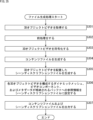
- FIG. 7 is a flowchart showing an example of the flow of file generation processing
- 2 is a block diagram showing a main configuration example of a client device
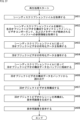
- FIG. 4 is a flowchart showing an example of the flow of reproduction processing
- It is a block diagram which shows the main structural examples of a computer.
- Non-Patent Document 1 (above)
- Non-Patent Document 2 (above)
- Non-Patent Document 3 (above)
- Non-Patent Document 4 (above)
- Non-Patent Document 5 (above)
- Non-Patent Document 6 (above)
- Patent document 1 (mentioned above)
- Patent document 2 (mentioned above)
- the content described in the non-patent documents and patent documents mentioned above and the content of other documents referred to in the non-patent documents and patent documents mentioned above are also the basis for determining the support requirements.
- glTF2.0 and its extensions described in Non-Patent Documents 1 to 5 terms used in 3D object configurations described in Patent Documents 1 and 2, and files in Non-Patent Document 6
- technical terms such as Parsing, Syntax, Semantics, etc. are also within the scope of the present disclosure even if they are not directly defined in the detailed description of the invention. Yes, and shall satisfy the support requirements of the claims.
- glTF The GL Transmission Format
- glTF2.0 is a format for arranging a 3D (three-dimensional) object in a three-dimensional space, as described in Non-Patent Document 1, for example.
- glTF2.0 for example, as shown in FIG. 1, it is composed of a JSON format file (.glTF), a binary file (.bin), and an image file (.png, .jpg, etc.).
- Binary files store binary data such as geometry and animation.
- Image files store data such as textures.
- a JSON format file is a scene description file written in JSON (JavaScript (registered trademark) Object Notation).
- a scene description is metadata that describes (a description of) a scene of 3D content. The description of this scene description defines what kind of scene it is.
- a scene description file is a file that stores such scene descriptions.
- a scene description file is also referred to as a scene description file in this disclosure.
- JSON format file consists of a list of key (KEY) and value (VALUE) pairs.
- KEY key
- VALUE value
- a key consists of a character string. Values consist of numbers, strings, booleans, arrays, objects, or nulls.
- JSON object that summarizes the "id”: 1 pair and the "name”: “tanaka” pair is defined as the value corresponding to the key (user).
- zero or more values can be arrayed using [] (square brackets).
- This array is also called a JSON array.
- a JSON object for example, can also be applied as an element of this JSON array.
- An example of the format is shown below.
- Fig. 2 shows the glTF objects (glTF objects) that can be written at the top level of a JSON format file and the reference relationships they can have.
- Oblong circles in the tree structure shown in FIG. 2 indicate objects, and arrows between the objects indicate reference relationships.
- objects such as "scene”, “node”, “mesh”, “camera”, “skin”, “material”, and “texture” are described at the top of the JSON format file.
- Fig. 3 shows a description example of such a JSON format file (scene description).
- the JSON format file 20 in FIG. 3 shows a description example of a part of the highest level.
- the top-level objects 21 used are all described at the top level.
- This top level object 21 is the glTF object shown in FIG.
- reference relationships between objects are indicated. More specifically, the reference relationship is indicated by specifying the index of the array element of the referenced object in the property of the higher-level object.
- FIG. 4 is a diagram illustrating a method of accessing binary data.
- binary data is stored in a buffer object.
- information for example, URI (Uniform Resource Identifier), etc.
- URI Uniform Resource Identifier
- FIG. 4 an accessor object and a buffer view can be created from an object such as a mesh, camera, skin, etc. for the buffer object. It can be accessed through an object (bufferView object).
- FIG. 5 shows a description example of a mesh object (mesh) in a JSON format file.
- vertex attributes such as NORMAL, POSITION, TANGENT, and TEXCORD_0 are defined as keys, and for each attribute, an accessor object to be referenced is specified as a value.
- Each glTF 2.0 object can store newly defined objects in an extension object.
- FIG. 6 shows a description example when defining a newly defined object (ExtensionExample). As shown in FIG. 6, when using a newly defined extension, its extension object name (ExtensionExample in the example of FIG. 6) is described in "extensionUsed” and “extensionRequired”. This indicates that this extension is an extension that should not be used, or that it is an extension that is required for loading.
- the client device acquires the scene description, acquires data of the 3D object based on the scene description, and generates a display image using the scene description and the data of the 3D object.
- MPEG Motion Picture Experts Group
- the presentation engine, media access function, etc. perform processing on the client device.
- the presentation engine 51 of the client device 50 acquires the initial value of the scene description and information for updating the scene description (hereinafter also referred to as update information). and generate a scene description for the processing target time.
- the presentation engine 51 analyzes the scene description and specifies media to be reproduced (video, audio, etc.).
- the presentation engine 51 requests the media access function (Media Access Function) 52 to acquire the media via the media access API (Media Access API (Application Program Interface)).
- Media Access Function Media Access Function
- the presentation engine 51 also sets pipeline processing, specifies buffers, and the like.
- the media access function 52 acquires various media data requested by the presentation engine 51 from the cloud, local storage, or the like.
- the media access function 52 supplies various data (encoded data) of the acquired media to the pipeline (Pipeline) 53 .
- the pipeline 53 decodes various data (encoded data) of the supplied media by pipeline processing, and supplies the decoded result to the buffer (Buffer) 54 .
- the buffer 54 holds various data of the supplied media.
- the presentation engine 51 performs rendering and the like using various media data held in the buffer 54 .
- Timed media is media data that changes in the direction of time, such as moving images in two-dimensional images.
- changing in the direction of time is also referred to as “dynamic.”
- static when it does not change in the time direction.
- glTF was only applicable to static data as media data (3D object content). In other words, glTF did not support dynamic media data.
- animation a method of switching static media data in the time direction
- glTF2.0 is applied, JSON format file is applied as scene description, and glTF is extended to handle timed media (e.g. video data) as media data. is being considered. For example, the following extensions are made to handle timed media.
- FIG. 8 is a diagram explaining extensions for handling timed media.
- the Moving Picture Experts Group (MPEG) media object (MPEG_media) is a glTF extension that specifies dynamic MPEG media attributes, such as uri, track, renderingRate, startTime, etc. is an object.
- an MPEG texture video object (MPEG_texture_video) is provided as an extension object (extensions) of the texture object (texture).
- the MPEG texture video object stores information of the accessor corresponding to the buffer object to be accessed. That is, the MPEG texture video object is an object that specifies the index of the accessor corresponding to the buffer in which the texture media specified by the MPEG media object (MPEG_media) is decoded and stored. .
- a texture object with an MPEG texture video object is called a video component.
- FIG. 9 is a diagram showing a description example of an MPEG media object (MPEG_media) and MPEG texture video object (MPEG_texture_video) in a scene description for explaining extensions for handling timed media.
- MPEG texture video object MPEG_texture_video
- MPEG_texture_video is set as extension objects (extensions) of the texture object (texture) in the second line from the top as follows.
- An accessor index (“2" in this example) is specified as the value of the MPEG video texture object.
- the MPEG media object (MPEG_media) is set as the extension object (extensions) of glTF in the 7th to 16th lines from the top as follows.
- Various information related to the MPEG media object such as the encoding and URI of the MPEG media object, are stored as the value of the MPEG media object.
- an MPEG buffer circular object (MPEG_buffer_circular) is provided as an extension object (extensions) of the buffer object (buffer).
- MPEG_buffer_circular an MPEG buffer circular object
- the MPEG buffer circular object contains information for dynamically storing data within the buffer object. For example, information such as information indicating the data length of the buffer header (bufferHeader) and information indicating the number of frames is stored in this MPEG buffer circular object.
- the buffer header stores information such as an index, a time stamp of frame data to be stored, a data length, and the like.
- an MPEG accessor timed object (MPEG_timed_accessor) is provided as an extension object (extensions) of the accessor object (accessor).
- the buffer view object (bufferView) referred to in the time direction may change (the position may change). Therefore, information indicating the referenced buffer view object is stored in this MPEG accessor timed object.
- the MPEG accessor timed object stores information indicating a reference to a buffer view object (bufferView) in which a timed accessor information header (timedAccessor information header) is described.
- the timed accessor information header is, for example, header information that stores information in dynamically changing accessor objects and buffer view objects.
- Non-Patent Document 3 discloses processing of dynamic mesh and texture video on the client.
- a dynamic mesh that is a dynamic mesh
- Indexes and the like are individually stored in buffers. These data may be encoded and stored in the buffer, or may be stored in the buffer without being encoded.
- a texture video is a dynamic texture that is pasted (also referred to herein as mapping) onto a dynamic mesh.
- the texture video is encoded by a 2D image encoding method (for example, HEVC (High Efficiency Video Coding)), decoded by the encoding method, and stored in a buffer different from this dynamic mesh.
- HEVC High Efficiency Video Coding
- Non-Patent Document 3 discloses a scene description that supports such texture video and dynamic mesh.
- FIG. 11 shows a main configuration example of objects in such a scene description.
- dynamic meshes are stored in buffers corresponding to accessors specified in the primitives attribute layer of the scene description.
- texture video is stored in buffers corresponding to accessors specified in the material layer of primitives in the scene description.
- VD texture View Dependent Texture
- mesh texture
- a conventional texture (also referred to as a VI texture (View Independent Texture) in this specification) consists of a texture that maps to the entire piece of mesh information M, as shown on the left side of FIG. Therefore, in the case of the VI texture format, all textures that make up the VI texture are mapped to the mesh information M without depending on the viewpoint. That is, the texture is mapped to the entire mesh information M regardless of the position and direction of the viewpoint (regardless of whether it is used for rendering).
- the VI texture data is formed as a UV texture map stored (also called packed) in a 2D plane of the UV coordinate system by chunks (also called patches). be done. That is, in this case, one mesh information M and one UV texture map are associated and encoded (that is, mesh and texture are associated one-to-one).
- VD textures are textures that are mapped onto meshes according to the viewpoint.
- a VD texture is composed of a captured image (camera video) obtained by capturing a 3D object from a certain viewpoint, as shown on the right side of FIG. 13, for example.
- a picked-up image is mapped onto the mesh from the direction of the viewpoint.
- the VD texture contains the texture of the portion of the mesh that is visible from that point of view. Therefore, in general, one VD texture cannot cover the entire texture of the mesh information M. Therefore, as shown on the right side of FIG. multiple VD textures are associated.
- a necessary VD texture (for example, a VD texture close to the rendering viewpoint position) is selected according to the position and direction of the viewpoint during rendering, and mapped to the mesh information M.
- the rendering (mapping) processing load is greater in the VD texture format.
- the processing load on the encoder side is smaller in the VD texture format.
- the code amount is larger in the VD texture format.
- the VD texture format is better suited to human perceptual characteristics, which tend to value texture resolution and fidelity over bumpy topography, and the subjective quality of rendered images for display is of high quality. be.
- VD textures can be mapped simultaneously to one mesh.
- "simultaneously mapped” indicates that "a state in which a plurality of VD textures are mapped to one mesh" exists at least one timing. The timing of mapping each of the plurality of VD textures may differ from each other.
- Patent Literature 2 discloses a data format called packed VD texture that packs a plurality of VD textures into one image and transmits the image to a client.
- VD textures 61 to 66 configured by captured images from different viewpoints are packed into a two-dimensional image 60 . That is, in the case of this packed VD texture, multiple VD textures are encoded as one image.
- the decoder decodes the bitstream to obtain the image, it extracts (also called unpacking) the desired VD texture from the image and maps it onto a mesh.
- the VD textures are generally packed with reduced resolution, so the subjective image quality of the display image is lower than in the VD texture format.
- this packed VD texture format as well, multiple unpacked VD textures can be mapped simultaneously to one mesh.
- packed VD textures and VD textures may be used together.
- an encoder may associate and encode a plurality of VD textures and packed VD textures for one mesh.
- the decoder may map both the VD texture and the unpacked VD texture of the packed VD texture to one mesh.
- Non-Patent Document 4 discloses a method of associating meshes with buffers in units of tiles in a scene description, as shown in FIG. 15, for example.
- an extension object is set for each tile in the attribute layer of primitives, and each tile is associated with a different accessor. Therefore, in this method, mesh data is stored in different buffers for each tile.
- the presentation engine (PE) can select and reconfigure the desired tiles.
- Non-Patent Document 5 discloses a method of linking multiple textures to a material layer of primitives, as shown in FIG. 16, for example.
- the extension object "MSFT_lod” is set as shown in a solid-line square frame 82, and textures are set as shown in a solid-line square frame 84 and a solid-line square frame 86.
- FIG. A different index is assigned to each LoD. That is, each LoD texture is associated with a different accessor. That is, textures for each LoD are stored in different buffers.
- the decoder's presentation engine selects and maps one of the multiple LoDs. For example, the presentation engine selects one LoD according to the viewpoint position. By doing so, the presentation engine can switch the LoD of the texture to be mapped according to, for example, a change in viewpoint position.
- ISOBMFF International Organization for Standardization Base Media File Format
- Non-Patent Document 4 a dynamic mesh can be associated with different accessors for each tile in the attribute layer of primitives, but it was not possible to associate video components with different accessors in the material layer. Also, in the method described in Non-Patent Document 5, multiple video components could not be used simultaneously.
- an information processing device for example, a file generation device
- a file generation device generates a scene description file, and in extensions for a 3D object video defined in the material layer of the scene description file, video components included in the 3D object video , a file generation unit that sets a component index having a different value for each video component. Multiple video components can be used simultaneously in one 3D object.
- a scene description file is generated, and in the extension for the 3D object video defined in the material layer of the scene description file, the video component included in the 3D object video , set a component index with a different value for each video component. Multiple video components can be used simultaneously in one 3D object.
- an information processing device for example, a playback device
- a display image generation unit that acquires a video component from the video component and generates a display image using the acquired video component.
- Multiple video components can be used simultaneously in one 3D object.
- the component index is set for a video component included in the 3D object video in the 3D object video extension defined in the material layer of the scene description, and has a different value for each video component.
- a video component included in the 3D object video is stored in a buffer corresponding to the video component based on the component index, and the video component is retrieved from the buffer based on the component index. and generating an image for display using the captured video component.
- Multiple video components can be used simultaneously in one 3D object.
- the component index is set for a video component included in the 3D object video in the 3D object video extension defined in the material layer of the scene description, and has a different value for each video component.
- the media access function (MAF) of the playback device can store the video components in different buffers based on the scene description. This allows the playback device's presentation engine to select the desired video components and map them to one object. In other words, scene descriptions can be used to simultaneously use multiple video components for a single object.
- Method 1 when method 1 is applied, an index may be set for each VD texture or packed VD texture as shown in the second row from the top of the table in FIG. 18 (method 1-1). In other words, VD textures and packed VD textures may be applied as video components.
- using means “mapping VD textures”.
- mipping multiple VD textures to one mesh can be said to be “simultaneously using multiple video components”.
- using means “mapping a plurality of VD textures unpacked from the packed VD textures”.
- to map multiple VD textures unpacked from a packed VD texture onto one mesh can be said to be “to use multiple video components simultaneously.”
- the video component may be a VD texture, which is a captured image of a 3D object captured from a predetermined viewpoint.
- the file generation unit may set a component index for each of a plurality of VD textures included in the 3D object video in the extension.
- the video component may be a packed VD texture in which a plurality of VD textures, which are captured images of a 3D object captured from a predetermined viewpoint, are packed.
- the file generator may set a component index for the packed VD texture in the extension.
- the video component may be a VD texture, which is a captured image of a 3D object captured from a predetermined viewpoint.
- the file processing unit may store a plurality of VD textures with different viewpoints in corresponding buffers based on the component index.
- the display image generator may acquire a desired VD texture from the buffer based on the component index. Then, the display image generation unit may map the acquired VD texture to the 3D object (mesh). Then, the display image generation unit may generate a display image using the 3D data (the mesh on which the VD texture is mapped).
- the video component may be a packed VD texture in which a plurality of VD textures, which are captured images of a 3D object captured from a predetermined viewpoint, are packed.
- the file processing unit may store the packed VD texture in the buffer corresponding to the packed VD texture based on the component index.
- the display image generator may obtain the packed VD texture from the buffer based on the component index. Then, the display image generator may unpack the desired VD texture from the packed VD texture thus acquired. The display image generator may then map the unpacked VD texture to the 3D object (mesh). Then, the display image generation unit may generate a display image using the 3D data (the mesh on which the VD texture is mapped).
- an extended object "MPEG_video_components" for 3D object video may be provided in the material layer of primitives, and each VD texture and packed VD texture may be associated with different accessors in the MPEG_video_components.
- MPEG_video_components may be provided in primitives instead of in the material layer of primitives.
- an index also called a component index
- a component index is an index having a different value for each video component as described above. 19 and 20, the component index has a different value for each VD texture or packed VD texture.
- an index "1" (“index”:1) is set for one VD texture ("vdTexture") as shown in a rectangular frame 112, and 1
- An index "2" (“index”:2) is set for one packed VD texture ("packedVdTexture").
- each VD texture and packed VD texture can be associated with different accessors, as in the example of FIG. Therefore, the media access function (MAF) of the playback device can store each of the VD textures and packed VD textures in different buffers based on the scene description. This allows the presentation engine of the playback device to select a desired VD texture or packed VD texture and map it onto the mesh. In other words, multiple VD textures and packed VD textures can be mapped simultaneously to one mesh using the scene description.
- the media access function (MAF) of the playback device can store each of the VD textures and packed VD textures in different buffers based on the scene description. This allows the presentation engine of the playback device to select a desired VD texture or packed VD texture and map it onto the mesh. In other words, multiple VD textures and packed VD textures can be mapped simultaneously to one mesh using the scene description.
- the video component may consist of only VD textures and may not include packed VD textures. That is, multiple VD textures associated with one mesh may be applied as multiple video components.
- the structure of the object of the scene description may be as shown in FIG.
- an extended object "MPEG_video_components" for 3D object video may be provided in the material layer of primitives, and each VD texture may be associated with a different accessor in the MPEG_video_components.
- MPEG_video_components may be provided in primitives instead of in the material layer of primitives.
- the video component may consist of only packed VD textures and may not include unpacked VD textures. That is, a packed VD texture in which multiple VD textures associated with one mesh are packed may be applied as multiple video components.
- the configuration of the object of the scene description may be as shown in FIG. That is, in the material layer of primitives, an extension object "MPEG_video_components" for 3D object video may be provided, and packed VD textures may be associated with accessors in MPEG_video_components.
- MPEG_video_components may be provided in primitives instead of in the material layer of primitives.
- Method 1-2 when method 1 is applied, as shown in the third row from the top of the table in FIG. 18, for each video component (geometry, attribute, occupancy) of V-PCC (Video-based Point Cloud Compression) An index may be set (method 1-2). That is, V-PCC geometry, attributes, and occupancy maps may be applied as video components.
- V-PCC Video-based Point Cloud Compression
- a point cloud is 3D data that shows the 3D shape of an object with a large number of points.
- Point cloud data consists of the geometry and attributes of each point.
- a geometry indicates the position of a point in three-dimensional space (eg, three-dimensional coordinates).
- Attribute indicates attribute information given to the point. Any information may be used as this attribute information. For example, color information, reflectance information, normal information, etc. may be included.
- V-PCC is one of the point cloud data encoding methods.
- the geometry and attributes are each packed into a 2D plane per patch and encoded as a 2D image (using a coding scheme for 2D images).
- V-PCC can attach occupancy maps to these geometries and attributes.
- An occupancy map is map information that indicates the extent to which geometry (and attributes) exist in a 2D image.
- An occupancy map is generated for a geometry-packed 2D image (also referred to herein as a geometry map) and an attribute-packed 2D image (also referred to herein as an attribute map), and the occupancy map is , are encoded using a coding scheme for 2D images, similar to geometry maps and attribute maps.
- the geometry map, attribute map, and occupancy map are each configured as a video component.
- the coded data of the point cloud includes the coded data of the geometry map, the coded data of the attribute map, and the coded data of the occupancy map.
- the coded data of the geometry map, the coded data of the attribute map, and the coded data of the occupancy map are each decoded using the 2D image coding method. Then, based on the occupancy map, (each patch of) the geometry is unpacked from the geometry map, and (each of the patches of) the attribute is unpacked from the attribute map. A point cloud is then reconstructed using the unpacked geometry and attributes.
- using means “reconfiguring the point cloud”.
- Reconstruction of this point cloud is done using geometry and attributes as described above.
- an occupancy map is used to unpack its geometry and attributes.
- the point cloud is reconstructed using the geometry map, the attribute map, and the occupancy map” can be said to be "the geometry map, the attribute map, and the occupancy map are used simultaneously.”
- V-PCC video components
- component indexes may be set for the video components, and each video component may be associated with a different accessor, as in the case of the VD textures and packed VD textures described above. That is, indexes with different values may be set for each of the geometry (geometry map), attribute (attribute map), and occupancy map, and may be associated with different accessors.
- the video component corresponds to a geometry map packed with point cloud geometry, an attribute map packed with attributes of the point cloud, and a geometry map and an attribute map. It may be an occupancy map that Also, the file generator may set component indexes having mutually different values for each of the geometry map, attribute map, and occupancy map in the extension.
- the video component corresponds to a geometry map packed with the geometry of the point cloud, an attribute map packed with the attributes of the point cloud, and a geometry map and an attribute map. It may be an occupancy map.
- the file processing unit may store the geometry map, the attribute map, and the occupancy map in corresponding buffers based on the component index.
- the display image generator may also obtain the geometry map, attribute map, and occupancy map from the buffer based on the component index, respectively. The display image generator may then reconstruct the point cloud using the obtained geometry map, attribute map, and occupancy map. Then, the display image generation unit may generate a display image using the reconstructed point cloud.
- Method 1-3 When method 1 is applied and VD texture is applied as a video component, camera parameters of VD texture may be stored as shown in the fourth row from the top of the table in FIG. 18 (method 1-3).
- a VD texture may be composed of a captured image captured from a certain viewpoint as described above.
- a scene description may store a camera parameter, which is a parameter related to imaging (camera) for generating the captured image, that is, a camera parameter corresponding to the VD texture. This camera parameter may be used, for example, when mapping a VD texture to a mesh.
- the file generation unit may further store camera parameters corresponding to VD textures in the 3D object video extension.
- the file processing unit may further store the camera parameters corresponding to the VD texture in the buffer corresponding to the VD texture.
- the display image generator may further acquire camera parameters corresponding to the desired VD texture from the buffer based on the component index. Then, the display image generation unit may map the VD texture to the 3D object using the acquired camera parameters.
- the camera parameter (“cameraParam”) corresponding to the VD texture is set in the extension object "MPEG_video_components" for 3D object video defined in the material layer. That is, the camera parameters for this VD texture are stored in the buffer.
- camera parameters may include parameters such as cam_id, intrinsic_param, Rs, Ts, distortion.
- cam_id is a camera identifier for identifying the camera.
- intrinsic_param indicates an internal parameter of the camera.
- Rs and Ts denote the extrinsic parameters of the camera.
- Rs indicates the orientation of the camera (viewpoint)
- Ts indicates the position of the camera (viewpoint).
- Distortion is a parameter indicating an output vector of distortion coefficients.
- the contents of the parameters included in the camera parameters stored in the scene description are arbitrary. For example, parameters other than the examples described above may be included, or some parameters of the examples described above may be omitted.
- an index (accessor index) is set for each VD texture in the camera parameter ("cameraParam"). That is, the camera parameters are stored in different buffers for each VD texture.
- the playback device can more easily map the VD textures to the mesh based on the camera parameters. can.
- an index may be set for each field of the camera parameter as shown in the fifth row from the top of the table in FIG. 18 (method 1-3-1). . That is, an index (also referred to as a field index) having a different value for each field may be set for each field of the camera parameters.
- the file generation unit may further set a field index having a different value for each field for each field of the camera parameters in the extension. .
- the file processing unit may store each field of the camera parameters in the corresponding buffer based on the field index.
- the display image generator may further acquire each field of the camera parameters corresponding to the desired VD texture from the buffer based on the field index. Then, the display image generation unit may map the VD texture to the 3D object using the acquired camera parameters.
- the field index is set for the camera parameter field in the extension and has a different value for each field.
- the index value "100” is set for the camera identifier cameraId. Also, an index value "101" is set for the internal parameter intrinsicParam. Also, an index value "102” is set for the external parameter Rs. Also, an index value “103” is set for the external parameter Ts. Also, an index value “104” is set for the output vector distortion of the distortion coefficients. That is, in the scene description, an index with a different value is set for each field with respect to the camera parameters. By doing so, the media access function of the playback device can store these camera parameters in different buffers for each field based on this scene description. Therefore, the presentation engine of the playback device can easily obtain the desired field of camera parameters by selecting a buffer based on this scene description.
- Method 1 when Method 1 is applied and a packed VD texture is applied as a video component, the camera parameters and packing metadata of the packed VD texture can be stored as shown in the sixth row from the top of the table in FIG. Good (Method 1-4).
- a packed VD texture contains multiple VD textures as described above.
- Camera parameters which are parameters related to imaging (camera) for generating each VD texture (captured image), that is, camera parameters corresponding to each VD texture packed in the packed VD texture, are stored in the scene description. good. This camera parameter may be used, for example, when mapping the unpacked VD texture to the mesh.
- packing metadata indicating where in the packed VD texture the VD texture is packed may be stored in the scene description. This packing metadata may be used, for example, to unpack VD textures from packed VD textures.
- the file generation unit may further store camera parameters and packing metadata corresponding to the packed VD texture in the extension.
- the file processing unit may further store the camera parameters and packing metadata corresponding to the packed VD texture in the buffer corresponding to the packed VD texture.
- the display image generator may further acquire camera parameters and packing metadata corresponding to the packed VD texture from the buffer based on the component index. Then, the display image generator may unpack the desired VD texture from the packed VD texture based on the obtained packing metadata. Then, the display image generation unit may map the VD texture to the 3D object using the acquired camera parameters.
- the camera parameter packedCameraParam
- packing metadata packedMeta
- the contents of the parameters included in the camera parameters are arbitrary. For example, parameters such as cam_id, intrinsic_param, Rs, Ts, distortion may be included.
- the camera parameters corresponding to the packed VD texture include camera parameters for each of the multiple VD textures. Therefore, in the example of FIG. 27, unlike the example of FIG. 24, a for loop is used to indicate each parameter for all cameras (VD textures). Note that the parameter camera_num indicates the number of cameras (VD textures).
- Fig. 28 shows an example of how to describe packing metadata in a scene description.
- Packing metadata includes information such as where each VD texture is packed in the packed VD texture.
- the packing metadata also uses a for loop to indicate each parameter for all cameras (VD textures), as in the case of the camera parameters shown in FIG. Note that the parameter camera_num indicates the number of cameras (VD textures).
- cam_id is a camera identifier for identifying the camera.
- src_width[i] is a parameter indicating the width (horizontal length) of the corresponding VD texture.
- src_height[i] is a parameter indicating the height (longitudinal length) of the corresponding VD texture.
- src_top[i] is a parameter indicating the position of the top edge of the corresponding VD texture.
- src_left[i] is a parameter indicating the position of the left edge of the corresponding VD texture. These parameters represent the unpacked values from the packed VD texture. Also, transform_type[i] is a parameter indicating arrangement information (rotation, etc.) of the packed VD texture.
- dst_width[i] is a parameter that indicates the width (horizontal length) of the corresponding VD texture.
- dst_height[i] is a parameter indicating the height (longitudinal length) of the corresponding VD texture.
- dst_top[i] is a parameter indicating the position of the top edge of the corresponding VD texture.
- dst_left[i] is a parameter indicating the position of the left edge of the corresponding VD texture.
- the packing metadata indicates which part of the VD texture is stored where in the packed VD texture.
- the contents of the parameters included in the packing metadata stored in the scene description are arbitrary.
- parameters other than the examples described above may be included, or some parameters of the examples described above may be omitted.
- indexes accessor indexes
- the index value "200" is set in the camera parameter ("packedCameraParam")
- the index value "201" is set in the packing metadata ("packedMeta”). That is, the camera parameters and packing metadata are stored in different buffers. Camera parameters are stored in a static buffer and packing metadata is stored in a circular buffer. Also, as shown in FIG. 27, camera parameters for all VD textures packed into a packed VD texture are collectively stored in one buffer. Similarly, as shown in FIG. 28, packing metadata for all VD textures packed into a packed VD texture are collectively stored in one buffer.
- the playback device can more easily unpack the VD texture based on the packing metadata. Also, by storing the camera parameters corresponding to the packed VD textures in the scene description, the playback device can more easily map the VD textures to the mesh based on the camera parameters.
- an index may be set for each VD texture packed in the packed VD texture (method 1 -4-1). That is, an index (also referred to as a VD texture index) having a different value for each corresponding VD texture may be set for camera parameters and packing metadata for each VD texture packed in a packed VD texture.
- the file generation unit further includes, in the extension, the camera parameter and packing metadata for each VD texture packed in the packed VD texture, the corresponding VD A VD texture index with a different value for each texture may be set.
- the file processing unit associates each camera parameter and packing metadata of the VD textures packed in the packed VD texture based on the VD texture index. May be stored in a buffer.
- the display image generator may further obtain camera parameters and packing metadata corresponding to the desired VD texture from the buffer based on the VD texture index. Then, the display image generator may unpack the desired VD texture from the packed VD texture based on the obtained packing metadata. Then, the display image generation unit may map the VD texture to the 3D object using the acquired camera parameters.
- the VD texture index is set for the camera parameter and packing metadata for each VD texture in the extension described above, and has a different value for each corresponding VD texture.
- the index value "100" is set for the camera parameter ("packedCameraParam_1") corresponding to the first VD texture packed in the packed VD texture.
- an index value "200” is set for the camera parameter ("packedCameraParam_2”) corresponding to the second VD texture packed in the packed VD texture. That is, a VD texture index is set for each camera parameter.
- the camera parameters are divided for each VD texture as described above. Therefore, the camera parameter description method is independent for each VD texture, as shown in FIG. 30, for example. Therefore, a for loop using camera_num like the example in FIG. 27 is unnecessary. Also, names that can identify the corresponding VD textures are applied as camera parameter names, such as "packedCameraParam_1" and "packedCameraParam_2", so cam_id is not necessary.
- the media access function of the playback device can store these camera parameters in different buffers for each corresponding VD texture based on this scene description. Therefore, the presentation engine of the playback device can easily acquire the desired VD texture camera parameters by selecting a buffer based on this scene description.
- the index value "101" is set for the packing metadata ("packedMeta_1") corresponding to the first VD texture packed in the packed VD texture.
- the index value "201” is set for the packing metadata ("packedMeta_2”) corresponding to the second VD texture packed in the packed VD texture. That is, a VD texture index is set for each packing metadata.
- the packing metadata is divided for each VD texture, as described above. Therefore, the packing metadata description method is independent for each VD texture, as shown in FIG. 31, for example. Therefore, a for loop using camera_num like the example in FIG. 28 is unnecessary. Also, names that can identify corresponding VD textures are applied as camera parameter names, such as "packedMeta_1" and "packedMeta_2", so cam_id is not necessary.
- the media access function of the playback device can store these packing metadata in different buffers for each corresponding VD texture based on this scene description. Therefore, the presentation engine of the playback device can easily acquire packing metadata of the desired VD texture by selecting a buffer based on this scene description.
- an index may be set for each field of camera parameters and packing metadata as shown in the eighth row from the top of the table in FIG. 18 (method 1-4 -2). That is, for each field of camera parameters and packing metadata, an index (also referred to as field index) having a different value for each field may be set as in the example of FIG.
- the file generation unit further sets a field index having a different value for each field for each field of camera parameters and packing metadata in the extension.
- the file processing unit may store each field of the camera parameters and the packing metadata in the corresponding buffer based on the field index.
- the display image generator may further acquire each field of camera parameters and packing metadata corresponding to the desired VD texture from the buffer based on the field index. Then, the display image generator may unpack the desired VD texture from the packed VD texture based on the obtained packing metadata. Then, the display image generation unit may map the VD texture to the 3D object using the acquired camera parameters.
- the field index is set for the camera parameter and packing metadata fields in the extension, and has a different value for each field.
- the media access function of the playback device can store these camera parameters and packing metadata in different buffers for each field based on this scene description. Therefore, the presentation engine of the playback device can easily obtain the desired fields of camera parameters and packing metadata by selecting buffers based on this scene description.
- method 1-4-1 and method 1-4-2 described above may be applied in combination.
- different index values may be set for each corresponding VD texture and each field for camera parameters and packing metadata.
- the index value "101" is set for the intrinsic parameter "intrinsicParam_1" included in the camera parameters corresponding to the first VD texture packed in the packed VD texture.
- an index value of "102” is set for the external parameter "Rs_1” corresponding to the first VD texture.
- an index value "103” is set for the external parameter "Ts_1” corresponding to the first VD texture.
- an index value "104” is set for the output vector "distortion_1" of the distortion coefficients corresponding to the first VD texture.
- index value " 201” is set.
- index value "202” is set for the packed VD texture arrangement information "transformType_1” corresponding to the first VD texture.
- index value "203” is set for the information "dst_video_1” regarding the VD texture packed in the packed VD texture corresponding to the first VD texture.
- the media access function of the playback device stores these camera parameters and packing metadata in different buffers for each corresponding VD texture and for each field based on this scene description. can do. Therefore, the presentation engine of the playback device can easily acquire the desired field of camera parameters and packing metadata corresponding to the desired VD texture by selecting a buffer based on this scene description.
- the accessors for each parameter type of the VD texture captured by the same camera are paired with the name (index_X).
- the presentation engine of the playback device obtains a field named "XXX_1" (XXX is an arbitrary character string) to obtain camera parameters and Packing metadata can be obtained. That is, the presentation engine of the playback device can easily acquire camera parameters and packing metadata for each corresponding VD texture.
- Method 1-5 when Method 1 is applied and a packed VD texture is applied as a video component, the media access function (MAF) unpacks the VD texture from the packed VD texture as shown in the ninth row from the top of the table in FIG. It may be packed and stored in a buffer (method 1-5).
- the media access function (MAF) unpacks the VD texture from the packed VD texture as shown in the ninth row from the top of the table in FIG. It may be packed and stored in a buffer (method 1-5).
- the file generator does not set the packed VD texture object in the material layer of the scene description.
- the media access function of the playback device generates a VD texture from the packed VD texture and stores the VD texture in the circular buffer referenced by the VD texture object in the material layer of the scene description.
- the presentation engine (PE) may perform processing in the same way as when VD textures are applied as video components.
- the media access function of the playback device may perform processing as described above. That is, the media access function generates a VD texture from the packed VD texture and stores the VD texture in the circular buffer referenced by the VD texture object in the material layer of the scene description.
- Method 1 when Method 1 is applied and a packed VD texture is applied as a video component, the media access function (MAF) unpacks the VD texture from the packed VD texture, as shown at the bottom of the table in FIG.
- the VD texture may be mapped onto a 3D object (mesh) to generate a VI texture (UV texture map) and stored in a buffer (Methods 1-6).
- the file generator does not set packed VD texture objects or VD texture objects in the material layer of the scene description.
- the playback device's media access function generates a VD texture from the packed VD texture, maps the VD texture to a 3D object (mesh), generates a VI texture (UV texture map), and assigns the UV texture map to "MPEG_media”. Store in the circular buffer referenced by the object.
- the presentation engine (PE) can perform the same processing as when VI textures (UV texture maps) are applied as video components.
- the media access function of the playback device should process as described above. good too.
- the track.codecs of the "MPEG_media" object may indicate that the object other than the VD texture refers to the VD texture or packed VD texture.
- the scheme_type of ISOBMFF that stores VD textures may be 'vdte'
- the scheme_type of ISOBMFF that stores packed VD textures may be 'pvdt'.
- codecs resv.vdte.*** indicates that VD textures are stored
- the media access function of the playback device will proceed as described above.
- the media access function generates a VD texture from the packed VD texture, maps that VD texture to a 3D object (mesh), generates a VI texture (UV texture map), maps that UV texture map to the "MPEG_media” object Store in the circular buffer referenced by .
- FIG. 34 is a block diagram showing an example of a configuration of a file generation device which is one aspect of an information processing device to which the present technology is applied.
- a file generation device 300 shown in FIG. 34 is a device that encodes 3D object content (eg, 3D data such as point cloud) and stores it in a file container such as ISOBMFF.
- the file generation device 300 also generates a scene description file for the 3D object content.
- FIG. 34 shows main elements such as the processing unit and data flow, and what is shown in FIG. 34 is not necessarily all. That is, in the file generation device 300, there may be processing units not shown as blocks in FIG. 34, or there may be processes or data flows not shown as arrows or the like in FIG.
- file generation device 300 has control unit 301 and file generation processing unit 302 .
- a control unit 301 controls a file generation processing unit 302 .
- the file generation processing unit 302 is controlled by the control unit 301 to perform processing related to file generation.
- the file generation processing unit 302 may acquire 3D object content data to be stored in a file.
- the file generation processing unit 302 may also generate a content file by storing the acquired 3D object content data in a file container.
- the file generation processing unit 302 may generate a scene description corresponding to the 3D object content and store it in the scene description file.
- the file generation processing unit 302 may output the generated file to the outside of the file generation device 300 .
- the file generation processing unit 302 may upload the generated file to a distribution server or the like.
- the file generation processing unit 302 has an input unit 311, a preprocessing unit 312, an encoding unit 313, a file generation unit 314, a recording unit 315, and an output unit 316.
- the input unit 311 performs processing related to acquisition of 3D object content data (3D data expressing the 3D structure of an object).
- the input unit 311 may acquire a 3D object video (dynamic 3D object) including multiple video components from outside the file generation device 300 as 3D object content data.
- a video component may be a VD texture, a packed VD texture, or both.
- the input unit 311 may obtain a dynamic mesh and multiple VD texture videos (dynamic VD textures).
- the input unit 311 may also acquire a dynamic mesh, multiple VD texture videos and packed VD texture videos (dynamic packed VD textures).
- the video component may also be a V-PCC video component (geometry, attributes, occupancy map).
- the video component is not limited to these examples, and may be any data that can be used simultaneously in one 3D object.
- the input unit 311 may supply the acquired 3D object content data to the preprocessing unit 312 .
- the preprocessing unit 312 executes processing related to preprocessing to be performed on the data of the 3D object content before encoding.
- the preprocessing unit 312 may acquire 3D object content data supplied from the input unit 311 .
- the preprocessing unit 312 may acquire information necessary for generating a scene description from the acquired 3D object content data or the like.
- the preprocessing unit 312 may also supply the acquired information to the file generation unit 314 .
- the preprocessing unit 312 may also supply the data of the 3D object content to the encoding unit 313 .
- the encoding unit 313 executes processing related to encoding of 3D object content data. For example, the encoding unit 313 may acquire 3D object content data supplied from the preprocessing unit 312 . Also, the encoding unit 313 may encode data of the acquired 3D object content to generate the encoded data.
- the encoding unit 313 may encode them respectively. At that time, the encoding unit 313 encodes the VD texture video using a 2D image encoding method. Note that when a packed VD texture video is supplied, the encoding unit 313 may encode the packed VD texture video. At that time, the encoding unit 313 encodes the packed VD texture video using a 2D image encoding method.
- the encoding unit 313 may also supply the encoded data of the generated 3D object content to the file generation unit 314.
- the file generation unit 314 performs processing related to generation of files and the like. For example, the file generation unit 314 may acquire encoded data of 3D object content supplied from the encoding unit 313 . Also, the file generation unit 314 may acquire information supplied from the preprocessing unit 312 . The file generation unit 314 may also generate a file container (content file) that stores the encoded data of the 3D object content supplied from the encoding unit 313 .
- the specification of this content file (file container) is arbitrary, and any file can be used as long as it can store the encoded data of the 3D object content. For example, it may be ISOBMFF.
- the file generation unit 314 may use the information supplied from the preprocessing unit 312 to generate a scene description corresponding to the encoded data of the 3D object content. The file generator 314 may then generate a scene description file and store the generated scene description. In addition, the file generation unit 314 may supply the generated file (ISOBMFF, scene description file, etc.) to the recording unit 315 .
- the recording unit 315 has an arbitrary recording medium such as a hard disk or a semiconductor memory, and executes processing related to data recording.
- the recording unit 315 may record the file or the like supplied from the file generation unit 314 on the recording medium.
- the recording unit 315 may read a file or the like recorded on the recording medium in accordance with a request from the control unit 301 or the output unit 316 or at a predetermined timing, and supply the file to the output unit 316 .
- the output unit 316 may acquire files and the like supplied from the recording unit 315 and output the files and the like to the outside of the file generation device 300 (for example, a distribution server, a reproduction device, etc.).
- the file generation device 300 for example, a distribution server, a reproduction device, etc.
- the file generation unit 314 generates a scene description file, and in the extension for the 3D object video defined in the material layer of the scene description file, the video included in the 3D object video
- a component index having a different value for each video component may be set for the component. Multiple video components can be used simultaneously in one 3D object.
- method 1-1 may be applied when method 1 is applied, and the video component may be a VD texture, which is a captured image of a 3D object captured from a predetermined viewpoint. Then, the file generation unit 314 may set a component index for each of a plurality of VD textures included in the 3D object video in the extension for the 3D object video described above.
- method 1-3 when method 1 is applied and VD texture is applied as a component, method 1-3 is applied, and the file generation unit 314 further adds the extension for the 3D object video described above to the VD texture. It may store camera parameters.
- method 1-3-1 when method 1-3 is applied, method 1-3-1 is applied, and file generation unit 314 further adds, in the extension for 3D object video described above, for each field of the camera parameter, A field index with a different value for each field may be set.
- method 1-1 may be applied when method 1 is applied, and the video component may be a packed VD texture in which multiple VD textures, which are captured images of a 3D object captured from a predetermined viewpoint, are packed. Then, the file generation unit 314 may set a component index for the packed VD texture in the 3D object video extension described above.
- method 1-4 when method 1 is applied and packed VD texture is applied as a component, method 1-4 is applied, and the file generation unit 314 further adds the extension for the 3D object video described above to the packed VD texture.
- the file generation unit 314 may store camera parameters and packing metadata to be used.
- method 1-4-1 when method 1-4 is applied, method 1-4-1 is applied, and the file generation unit 314 further generates a A VD texture index having a different value for each corresponding VD texture may be set for each camera parameter and packing metadata.
- method 1-4-2 when method 1-4 is applied, method 1-4-2 is applied, and the file generation unit 314 further adds each field of camera parameters and packing metadata in the extension for 3D object video described above. , a field index with a different value for each field may be set.
- method 1-2 is applied when method 1 is applied, and the video component is converted into a geometry map packed with the geometry of the point cloud, an attribute map packed with the attributes of the point cloud, and a geometry map and attributes. It may be an occupancy map corresponding to the map. Then, the file generation unit 314 may set component indexes having different values for each of the geometry map, attribute map, and occupancy map in the extension for 3D object video described above.
- Scene description corresponding to multiple video components> may be applied.
- a plurality of the present technologies may be appropriately combined and applied.
- the file generation device 300 can generate a scene description that associates a plurality of video components that can be used simultaneously for one object with different accessors. Therefore, the playback device can use the scene description to simultaneously use multiple video components for one object.
- the input unit 311 of the file generation device 300 acquires 3D object video (dynamic 3D data) in step S301.
- the input unit 311 acquires a 3D object video including multiple video components as this 3D data.
- the preprocessing unit 312 performs preprocessing on the 3D object video.
- the preprocessing unit 312 acquires information used for generating a scene description, which is spatial arrangement information for arranging one or more 3D objects in 3D space, from the 3D object video.
- step S303 the file generation unit 314 encodes the 3D object video acquired in step S301 and generates the encoded data.
- step S304 the file generation unit 314 generates a content file (for example, ISOBMFF) that stores the encoded data.
- a content file for example, ISOBMFF
- step S305 the file generation unit 314 generates a scene description file.
- This scene description file stores a scene description in which 3D objects represented by the 3D object video acquired in step S301 are arranged in 3D space.
- step S306 the file generation unit 314 sets, in the scene description, reference information to each buffer in which data constituting the 3D object video is stored.
- This 3D object video consists of a dynamic mesh, multiple video components, metadata, and so on.
- the file generation unit 314 sets reference information to each buffer in the scene description so that these constituent data (dynamic mesh, each video component, and metadata) are stored in different buffers.
- the file generation unit 314 applies the method 1, and in the extension for the 3D object video defined in the material layer of the scene description file, for the video component included in the 3D object video, the video component You may set a component index with a different value for each. Multiple video components can be used simultaneously in one 3D object.
- the recording unit 315 records the generated scene description file and content file on the recording medium.
- the output unit 316 reads the scene description file, the content file, and the like from the recording medium, and outputs the read files to the outside of the file generation device 300 at a predetermined timing.
- the output unit 316 may transmit (upload) the scene description file and the content file to another device such as a distribution server or a playback device via a communication medium such as a network.
- the output unit 316 may record the scene description file and the content file on an external recording medium such as a removable medium. In that case, the output file may be supplied to another device (distribution server, playback device, etc.) via the external recording medium, for example.
- step S307 ends, the file generation process ends.
- the file generation device 300 can generate a scene description that associates multiple video components that can be used simultaneously for one object with different accessors. Therefore, the playback device can use the scene description to simultaneously use multiple video components for one object.
- method 1-1 may be applied and the video component may be a VD texture, which is a captured image of a 3D object captured from a predetermined viewpoint.
- the file generation unit 314 may set a component index for each of the plurality of VD textures included in the 3D object video in the extension for the 3D object video described above.
- the file generation unit 314 further adds the camera corresponding to the VD texture to the extension for the 3D object video described above. parameters may be stored.
- the file generation unit 314 further adds each of the camera parameters in the extension for the 3D object video described above.
- a field index having a different value for each field may be set for the field.
- method 1-1 may be applied, and the video component may be a packed VD texture in which a plurality of VD textures, which are captured images of a 3D object captured from a predetermined viewpoint, are packed. Then, in step S306, the file generation unit 314 may set a component index for the packed VD texture in the 3D object video extension described above.
- the file generation unit 314 adds the camera corresponding to the packed VD texture to the extension for the 3D object video described above. May store parameters and packing metadata.
- the file generation unit 314 further performs packing to the packed VD texture in the extension for the 3D object video described above.
- a VD texture index with a different value for each corresponding VD texture may be set for the camera parameters and packing metadata for each VD texture.
- step S306 the file generation unit 314 further adds camera parameters and packing metadata to the extension for 3D object video described above.
- a field index having a different value for each field may be set for each field of data.
- the video component is defined as a geometry map packed with the geometry of the point cloud, an attribute map packed with the attributes of the point cloud, and an occupancy map corresponding to the geometry map and the attribute map. good too.
- the file generation unit 314 may set component indexes having different values for each of the geometry map, attribute map, and occupancy map in the 3D object video extension described above. .
- Scene description corresponding to multiple video components> may be applied.
- a plurality of the present technologies may be appropriately combined and applied.
- FIG. 36 is a block diagram showing an example of a configuration of a client device, which is one aspect of an information processing device to which the present technology is applied.
- a client device 400 shown in FIG. 36 is a playback device that performs playback processing of 3D object content based on scene descriptions.
- the client device 400 reproduces 3D object data stored in the content file generated by the file generation device 300 .
- the client device 400 performs processing related to the reproduction based on the scene description.
- FIG. 36 shows main elements such as processing units and data flow, and what is shown in FIG. 36 is not necessarily all. That is, in the client device 400, there may be processing units not shown as blocks in FIG. 36, or there may be processes and data flows not shown as arrows or the like in FIG.
- the client device 400 has a control unit 401 and a reproduction processing unit 402 as shown in FIG.
- the control unit 401 performs processing related to control of the reproduction processing unit 402 .
- the reproduction processing unit 402 performs processing related to reproduction of 3D object data.
- the reproduction processing unit 402 has a file acquisition unit 411 , a file processing unit 412 , a decoding unit 413 , a display information generation unit 414 , a display unit 415 and a display control unit 416 .
- the file acquisition unit 411 performs processing related to file acquisition.
- the file acquisition unit 411 may acquire a file or the like supplied from outside the client device 400 such as the distribution server or the file generation device 300 .
- the file acquisition unit 411 may acquire a file or the like stored in a local storage (not shown).
- the file acquisition unit 411 may acquire a scene description file.
- the file acquisition unit 411 may acquire a content file.
- the file acquisition section 411 may supply the acquired file to the file processing section 412 .
- the file acquisition unit 411 may perform processing related to this file acquisition under the control of the file processing unit 412 .
- the file acquisition unit 411 may acquire the file requested by the file processing unit 412 from an external or local storage and supply it to the file processing unit 412 .
- the file processing unit 412 performs processing related to processing of files and the like.
- the file processing unit 412 has the function of the media access function (MAF) 52 in the configuration described with reference to FIG. good.
- MAF media access function
- the file processing unit 412 may control the file acquisition unit 411 under the control of the display information generation unit 414 to acquire the scene description file from the outside of the client device 400, local storage, or the like.
- the file processing unit 412 may also supply the scene description file to the display information generating unit 414 .
- the file processing unit 412 controls the file acquisition unit 411 under the control of the display information generation unit 414, and stores data (for example, encoding of 3D object video) stored in a content file outside the client device 400 or in a local storage. data, etc.) may be obtained.
- the file processing unit 412 also supplies the encoded data such as the 3D object video to the decoding unit 413 to decode it, and stores the obtained data in a buffer (not shown) (corresponding to the buffer 54 in FIG. 7). good too. In other words, it can be said that the file processing unit 412 substantially stores this data in a buffer (not shown) (corresponding to the buffer 54 in FIG. 7).
- the file processing unit 412 may supply information regarding image display (for example, scene description, etc.) to the display control unit 416 .
- the decoding unit 413 performs processing related to decoding.
- the decoding unit 413 has the function of the pipeline 53 (decoder) in the configuration described with reference to FIG. good.
- the decoding unit 413 may decode encoded data such as 3D object video supplied from the file processing unit 412 under the control of the file processing unit 412 (media access function 52). Further, the decoding unit 413 stores the data (video component, etc.) obtained by the decoding in a buffer (corresponding to the buffer 54 in FIG. 7), not shown, under the control of the file processing unit 412 (media access function 52). may At that time, the decoding unit 413 stores the data (video component, etc.) obtained by the decoding in the buffer linked to the data by the scene description.
- the display information generation unit 414 performs processing related to generation of display images under the control of the display control unit 416 . Therefore, the display information generation unit 414 can also be said to be a display image generation unit.
- the display information generation unit 414 may have the function of the presentation engine (PE) 51 in the configuration described with reference to FIG. .
- the display information generation unit 414 may control the file processing unit 412 (media access function 52) to acquire the scene description file.
- the display information generation unit 414 controls the file processing unit 412 (media access function 52) based on the scene description stored in the scene description file to obtain desired data (for example, 3D object video encoded data, etc.) may be acquired.
- the display information generation unit 414 may also acquire desired data from a buffer (not shown) (corresponding to the buffer 54 in FIG. 7) based on the scene description. Also, the display information generation unit 414 may reconstruct a 3D object video (3D data) using the acquired data. Also, the display information generation unit 414 may perform rendering using the 3D object video to generate a display image. This display image is a 2D image of the 3D object viewed from the specified viewpoint position. Further, the display information generation unit 414 may supply the generated display information to the display unit 415 to display it.
- a buffer not shown
- the display information generation unit 414 may reconstruct a 3D object video (3D data) using the acquired data. Also, the display information generation unit 414 may perform rendering using the 3D object video to generate a display image. This display image is a 2D image of the 3D object viewed from the specified viewpoint position. Further, the display information generation unit 414 may supply the generated display information to the display unit 415 to display it.
- the display unit 415 has a display device and performs processing related to image display. For example, the display unit 415 may acquire display information supplied from the display information generation unit 414 and display it using the display device.
- the display control unit 416 executes processing related to image display control. For example, the display control unit 416 may acquire information such as scene descriptions supplied from the file processing unit 412 . Also, the display control unit 416 may control the display information generation unit 414 based on the information.
- scene description corresponding to a plurality of video components> may be applied.
- method 1 may be applied, and the file processing unit 412 may store video components included in the 3D object video in buffers corresponding to the video components based on the component index. Also, the display information generation unit 414 may acquire a video component from the buffer based on the component index and generate a display image using the acquired video component.
- method 1-1 may be applied when method 1 is applied, and the video component may be a VD texture, which is a captured image of a 3D object captured from a predetermined viewpoint. Then, based on the component index, the file processing unit 412 may store a plurality of VD textures with different viewpoints in corresponding buffers. Also, the display information generator 414 may acquire the desired VD texture from the buffer based on the component index. Then, the display information generation unit 414 may map the acquired VD texture to the 3D object (mesh). Then, the display information generation unit 414 may generate a display image using the 3D data (mesh to which the VD texture is mapped).
- method 1-3 when method 1 is applied and VD texture is applied as a component, method 1-3 is applied, and the file processing unit 412 further stores the camera parameter corresponding to the VD texture in the buffer corresponding to the VD texture. may be stored. Also, the display information generator 414 may further acquire camera parameters corresponding to the desired VD texture from the buffer based on the component index. Then, the display information generation unit 414 may map the VD texture to the 3D object using the acquired camera parameters.
- method 1-3-1 when method 1-3 is applied, method 1-3-1 is applied, and file processing unit 412 stores each field of the camera parameter in the corresponding buffer based on the field index. good too.
- the display information generator 414 may further acquire each field of camera parameters corresponding to the desired VD texture from the buffer based on the field index. Then, the display information generation unit 414 may map the VD texture to the 3D object using the acquired camera parameters.
- the field index is set for the camera parameter field in the extension for 3D object video described above, and has a different value for each field.
- method 1-1 may be applied when method 1 is applied, and the video component may be a packed VD texture in which multiple VD textures, which are captured images of a 3D object captured from a predetermined viewpoint, are packed.
- the file processing unit 412 may store the packed VD texture in the buffer corresponding to the packed VD texture based on the component index.
- the display information generator 414 may acquire the packed VD texture from the buffer based on the component index. Then, the display information generation unit 414 may unpack the desired VD texture from the packed VD texture thus acquired. The display information generator 414 may then map the unpacked VD texture to the 3D object. Then, the display information generation unit 414 may generate a display image using the 3D data (mesh to which the VD texture is mapped).
- method 1-4 when method 1 is applied and packed VD texture is applied as a component, method 1-4 is applied, and file processing unit 412 further converts the camera parameters and packing metadata corresponding to the packed VD texture to its It may be stored in a buffer corresponding to a packed VD texture. Also, the display information generator 414 may further acquire camera parameters and packing metadata corresponding to the packed VD texture from the buffer based on the component index. Then, the display information generation unit 414 may unpack the desired VD texture from the packed VD texture based on the obtained packing metadata. Then, the display information generation unit 414 may map the VD texture to the 3D object using the acquired camera parameters.
- method 1-4-1 is applied when method 1-4 is applied, and the file processing unit 412 calculates each camera parameter and Packing metadata may be stored in their respective buffers.
- the display information generator 414 may further acquire camera parameters and packing metadata corresponding to the desired VD texture from the buffer based on the VD texture index. Then, the display information generation unit 414 may unpack the desired VD texture from the packed VD texture based on the obtained packing metadata. Then, the display information generation unit 414 may map the VD texture to the 3D object using the acquired camera parameters.
- the VD texture index is set for the camera parameter and packing metadata for each VD texture in the 3D object video extension described above, and has a different value for each corresponding VD texture.
- method 1-4-2 is applied when method 1-4 is applied, and file processing unit 412 stores each field of the camera parameters and packing metadata based on the field index in the corresponding buffer.
- the display information generation unit 414 may further acquire each field of camera parameters and packing metadata corresponding to the desired VD texture from the buffer based on the field index. Then, the display information generation unit 414 may unpack the desired VD texture from the packed VD texture based on the obtained packing metadata. Also, the display information generation unit 414 may map the VD texture to the 3D object using the acquired camera parameters.
- the field index is set for the camera parameter and packing metadata fields in the extension for 3D object video described above, and has a different value for each field.
- method 1-2 is applied when method 1 is applied, and the video component is converted into a geometry map packed with the geometry of the point cloud, an attribute map packed with the attributes of the point cloud, and a geometry map and attributes. It may be an occupancy map corresponding to the map.
- the file processing unit 412 may store the geometry map, the attribute map, and the occupancy map in their corresponding buffers based on the component index.
- the display information generator 414 may also obtain the geometry map, attribute map, and occupancy map from the buffer based on the component index. The display information generator 414 may then reconstruct the point cloud using the acquired geometry map, attribute map, and occupancy map. Then, the display information generation unit 414 may generate a display image using the reconstructed point cloud.
- Scene description corresponding to multiple video components> may be applied.
- a plurality of the present technologies may be appropriately combined and applied.
- the client device 400 can store multiple video components that can be used simultaneously for one object in different buffers based on the scene description. Therefore, the client device 400 can simultaneously use multiple video components for one object using the scene description.
- the file acquisition unit 411 of the client device 400 acquires the scene description file in step S401.
- step S402 the display information generation unit 414 analyzes the scene description file and acquires reference information to the buffer in which each data (for example, each video component) constituting the 3D object video is stored.
- the display information generation unit 414 controls the file processing unit 412 according to the scene description file to acquire encoded data of the 3D object video.
- the file processing unit 412 controls the file acquisition unit 411 under the control of the display information generation unit 414 to acquire the encoded data of the 3D object video.
- the file acquisition unit 411 acquires the encoded data of the 3D object video stored in the content file such as the outside of the client device 400 or local storage.
- step S404 the decoding unit 413 decodes the encoded data of the 3D object video under the control of the file processing unit 412.
- step S405 the file processing unit 412 controls the decoding unit 413 so that the data obtained by decoding in step S404 (data constituting the 3D object video) is stored in a buffer (not shown in FIG. 7) according to the scene description. buffer 54).
- the decoding unit 413 stores the data obtained by decoding in step S404 (data constituting the 3D object video) in the buffer associated with the data in the scene description.
- the file processing unit 412 (the decoding unit 413 controlled by the file processing unit 412) applies Method 1 to map each video component included in the 3D object video to the corresponding video component based on the component index. May be stored in a buffer.
- step S406 the display information generation unit 414 reads (acquires) configuration data (video components, etc.) of the 3D object video from the buffer according to the scene description.
- step S407 the display information generation unit 414 reconstructs the 3D object video using the configuration data (video component, etc.).
- step S408 the display information generation unit 414 reconstructs a scene from the 3D object video according to the scene description and generates a display image.
- the display information generator 414 may apply Method 1 and, in step S406, obtain the video component from its buffer based on the component index. Also, the display information generation unit 414 may apply method 1 and generate a display image using the acquired video component in steps S407 and S408.
- step S409 the display unit 415 displays the display image.
- step S409 ends, the reproduction process ends.
- the client device 400 can store multiple video components that can be used simultaneously for one object in different buffers based on the scene description. Therefore, the client device 400 can simultaneously use multiple video components for one object using the scene description.
- method 1-1 may be applied and the video component may be a VD texture, which is a captured image of a 3D object captured from a predetermined viewpoint.
- the file processing unit 412 (the decoding unit 413 controlled by the file processing unit 412) stores a plurality of VD textures with different viewpoints in corresponding buffers based on the component indexes. good too.
- the display information generator 414 may acquire the desired VD texture from the buffer based on the component index.
- the display information generation unit 414 may map the acquired VD texture to the 3D object (mesh).
- the display information generation unit 414 may generate a display image using the 3D data (the mesh on which the VD texture is mapped).
- step S405 file processing unit 412 (decoding unit 413 controlled by file processing unit 412) further supports VD texture.
- camera parameters may be stored in the buffer corresponding to that VD texture.
- step S406 the display information generator 414 may further acquire camera parameters corresponding to the desired VD texture from the buffer based on the component index. Then, in step S407, the display information generation unit 414 may map the VD texture to the 3D object using the acquired camera parameters.
- method 1-3-1 is applied when method 1-3 is applied, and in step S405, file processing unit 412 (decryption unit 413 controlled by file processing unit 412) performs decoding based on the field index.
- each field of camera parameters may be stored in a corresponding buffer.
- the display information generator 414 may further acquire each field of camera parameters corresponding to the desired VD texture from the buffer based on the field index.
- the display information generation unit 414 may map the VD texture to the 3D object using the acquired camera parameters.
- the field index is set for the camera parameter field in the extension for 3D object video described above, and has a different value for each field.
- the video component may be a packed VD texture in which a plurality of VD textures, which are captured images of a 3D object captured from a predetermined viewpoint, are packed.
- the file processing unit 412 (the decoding unit 413 controlled by the file processing unit 412) may store the packed VD texture in the buffer corresponding to the packed VD texture based on the component index.
- the display information generator 414 may acquire the packed VD texture from the buffer based on the component index. Then, the display information generation unit 414 may unpack the desired VD texture from the packed VD texture thus acquired.
- step S407 the display information generation unit 414 may map the unpacked VD texture to the 3D object. Then, in step S408, the display information generation unit 414 may generate a display image using the 3D data (the mesh on which the VD texture is mapped).
- the file processing unit 412 (the decoding unit 413 controlled by the file processing unit 412) further converts the packed VD texture into Corresponding camera parameters and packing metadata may be stored in the buffer corresponding to that packed VD texture.
- the display information generator 414 may further acquire camera parameters and packing metadata corresponding to the packed VD texture from the buffer based on the component index. Then, the display information generation unit 414 may unpack the desired VD texture from the packed VD texture based on the obtained packing metadata. Then, in step S407, the display information generation unit 414 may map the VD texture to the 3D object using the acquired camera parameters.
- each camera parameter and packing metadata of the VD textures packed in the packed VD texture may be stored in corresponding buffers.
- the display information generator 414 may further acquire camera parameters and packing metadata corresponding to the desired VD texture from the buffer based on the VD texture index. Then, the display information generation unit 414 may unpack the desired VD texture from the packed VD texture based on the obtained packing metadata. Then, in step S407, the display information generation unit 414 may map the VD texture to the 3D object using the acquired camera parameters.
- the VD texture index is set for the camera parameter and packing metadata for each VD texture in the 3D object video extension described above, and has a different value for each corresponding VD texture.
- step S405 file processing unit 412 (decoding unit 413 controlled by file processing unit 412) performs , camera parameters and packing metadata fields may be stored in respective buffers.
- step S406 the display information generation unit 414 may further acquire each field of camera parameters and packing metadata corresponding to the desired VD texture from the buffer based on the field index. Then, the display information generation unit 414 may unpack the desired VD texture from the packed VD texture based on the obtained packing metadata. Then, in step S407, the display information generation unit 414 may map the VD texture to the 3D object using the acquired camera parameters.
- the field index is set for the camera parameter and packing metadata fields in the extension for 3D object video described above, and has a different value for each field.
- the video component is defined as a geometry map packed with the geometry of the point cloud, an attribute map packed with the attributes of the point cloud, and an occupancy map corresponding to the geometry map and the attribute map.
- the file processing unit 412 (the decoding unit 413 controlled by the file processing unit 412) stores the geometry map, the attribute map, and the occupancy map in the corresponding buffers based on the component index.
- the display information generator 414 may acquire the geometry map, attribute map, and occupancy map from the buffer based on the component index.
- the display information generator 414 may reconstruct the point cloud using the acquired geometry map, attribute map, and occupancy map.
- the display information generation unit 414 may generate a display image using the reconstructed point cloud.
- Scene description corresponding to multiple video components> may be applied.
- a plurality of the present technologies may be appropriately combined and applied.
- the series of processes described above can be executed by hardware or by software.
- a program that constitutes the software is installed in the computer.
- the computer includes, for example, a computer built into dedicated hardware and a general-purpose personal computer capable of executing various functions by installing various programs.
- FIG. 38 is a block diagram showing a hardware configuration example of a computer that executes the series of processes described above by a program.
- a CPU Central Processing Unit
- ROM Read Only Memory
- RAM Random Access Memory
- An input/output interface 910 is also connected to the bus 904 .
- An input unit 911 , an output unit 912 , a storage unit 913 , a communication unit 914 and a drive 915 are connected to the input/output interface 910 .
- the input unit 911 consists of, for example, a keyboard, mouse, microphone, touch panel, input terminal, and the like.
- the output unit 912 includes, for example, a display, a speaker, an output terminal, and the like.
- the storage unit 913 is composed of, for example, a hard disk, a RAM disk, a nonvolatile memory, or the like.
- the communication unit 914 is composed of, for example, a network interface.
- Drive 915 drives removable media 921 such as a magnetic disk, optical disk, magneto-optical disk, or semiconductor memory.
- the CPU 901 loads, for example, a program stored in the storage unit 913 into the RAM 903 via the input/output interface 910 and the bus 904, and executes the above-described series of programs. is processed.
- the RAM 903 also appropriately stores data necessary for the CPU 901 to execute various processes.
- a program executed by a computer can be applied by being recorded on removable media 921 such as package media, for example.
- the program can be installed in the storage unit 913 via the input/output interface 910 by loading the removable medium 921 into the drive 915 .
- This program can also be provided via wired or wireless transmission media such as local area networks, the Internet, and digital satellite broadcasting.
- the program can be received by the communication unit 914 and installed in the storage unit 913 .
- this program can be installed in the ROM 902 or the storage unit 913 in advance.
- This technology can be applied to any encoding/decoding scheme.
- this technology can be applied to any configuration.
- the present technology can be applied to various electronic devices.
- the present technology includes a processor (e.g., video processor) as a system LSI (Large Scale Integration), etc., a module (e.g., video module) using a plurality of processors, etc., a unit (e.g., video unit) using a plurality of modules, etc.
- a processor e.g., video processor
- LSI Large Scale Integration
- module e.g., video module
- a unit e.g., video unit
- it can be implemented as a part of the configuration of the device, such as a set (for example, a video set) in which other functions are added to the unit.
- the present technology can also be applied to a network system configured by a plurality of devices.
- the present technology may be implemented as cloud computing in which a plurality of devices share and jointly process via a network.
- this technology is implemented in cloud services that provide image (moving image) services to arbitrary terminals such as computers, AV (Audio Visual) equipment, portable information processing terminals, and IoT (Internet of Things) devices. You may make it
- a system means a set of multiple components (devices, modules (parts), etc.), and it does not matter whether all the components are in the same housing. Therefore, a plurality of devices housed in separate housings and connected via a network, and a single device housing a plurality of modules in one housing, are both systems. .
- Systems, devices, processing units, etc. to which this technology is applied can be used in any field, such as transportation, medical care, crime prevention, agriculture, livestock industry, mining, beauty, factories, home appliances, weather, and nature monitoring. . Moreover, its use is arbitrary.
- this technology can be applied to systems and devices used to provide viewing content. Further, for example, the present technology can also be applied to systems and devices used for traffic, such as traffic condition supervision and automatic driving control. Further, for example, the technology can be applied to systems and devices that serve security purposes. Also, for example, the present technology can be applied to systems and devices used for automatic control of machines and the like. Furthermore, for example, the technology can be applied to systems and devices used in agriculture and animal husbandry. The present technology can also be applied to systems and devices that monitor natural conditions such as volcanoes, forests, oceans, and wildlife. Further, for example, the technology can be applied to systems and devices used for sports.
- “flag” is information for identifying a plurality of states, not only information used for identifying two states of true (1) or false (0), Information that can identify the state is also included. Therefore, the value that this "flag” can take may be, for example, two values of 1/0, or three or more values. That is, the number of bits constituting this "flag” is arbitrary, and may be 1 bit or multiple bits.
- the identification information (including the flag) is assumed not only to include the identification information in the bitstream, but also to include the difference information of the identification information with respect to certain reference information in the bitstream.
- the "flag” and “identification information” include not only that information but also difference information with respect to reference information.
- various types of information (metadata, etc.) related to the encoded data may be transmitted or recorded in any form as long as they are associated with the encoded data.
- the term "associating" means, for example, making it possible to use (link) data of one side while processing the other data. That is, the data associated with each other may be collected as one piece of data, or may be individual pieces of data.
- information associated with encoded data (image) may be transmitted on a different transmission line from that of the encoded data (image).
- the information associated with the encoded data (image) may be recorded on a different recording medium (or another recording area of the same recording medium) than the encoded data (image). good.
- this "association" may be a part of the data instead of the entire data. For example, an image and information corresponding to the image may be associated with each other in arbitrary units such as multiple frames, one frame, or a portion within a frame.
- a configuration described as one device may be divided and configured as a plurality of devices (or processing units).
- the configuration described above as a plurality of devices (or processing units) may be collectively configured as one device (or processing unit).
- part of the configuration of one device (or processing unit) may be included in the configuration of another device (or other processing unit) as long as the configuration and operation of the system as a whole are substantially the same. .
- the above-described program may be executed on any device.
- the device should have the necessary functions (functional blocks, etc.) and be able to obtain the necessary information.
- each step of one flowchart may be executed by one device, or may be executed by a plurality of devices.
- the plurality of processes may be executed by one device, or may be shared by a plurality of devices.
- a plurality of processes included in one step can also be executed as processes of a plurality of steps.
- the processing described as multiple steps can also be collectively executed as one step.
- a computer-executed program may be configured such that the processing of the steps described in the program is executed in chronological order according to the order described in this specification, in parallel, or when calls are executed. It may also be executed individually at necessary timings such as when it is interrupted. That is, as long as there is no contradiction, the processing of each step may be executed in an order different from the order described above. Furthermore, the processing of the steps describing this program may be executed in parallel with the processing of other programs, or may be executed in combination with the processing of other programs.
- the present technology can also take the following configuration.
- a file processing unit that stores a video component included in a 3D object video in a buffer corresponding to the video component based on the component index; a display image generation unit that acquires the video component from the buffer based on the component index and generates a display image using the acquired video component,
- a plurality of said video components can be used simultaneously in one 3D object,
- the component index is set for the video component included in the 3D object video in the extension for the 3D object video defined in the material layer of the scene description, and has a different value for each video component.
- the video component is a VD texture that is a captured image of the 3D object captured from a predetermined viewpoint;
- the file processing unit stores the plurality of VD textures with different viewpoints in the corresponding buffers based on the component indexes,
- the display image generation unit acquires the desired VD texture from the buffer based on the component index, maps the acquired VD texture to the 3D object, and generates the display image.
- the file processing unit further stores camera parameters corresponding to the VD texture in the buffer corresponding to the VD texture,
- the display image generation unit further obtains the camera parameters corresponding to the desired VD texture from the buffer based on the component index, and converts the VD texture to the 3D object using the obtained camera parameters.
- the information processing apparatus according to (2), which maps.
- the file processing unit stores each field of the camera parameter in the corresponding buffer based on the field index;
- the display image generation unit further obtains each field of the camera parameters corresponding to the desired VD texture from the buffer based on the field index, and converts the VD texture using the obtained camera parameters. map to a 3D object,
- the information processing apparatus according to (3) wherein the field index is set for the field of the camera parameter in the extension and has a different value for each field.
- the video component is a packed VD texture in which a plurality of VD textures, which are captured images of the 3D object captured from a predetermined viewpoint, are packed;
- the file processing unit stores the packed VD texture in the buffer corresponding to the packed VD texture based on the component index,
- the display image generation unit obtains the packed VD texture from the buffer based on the component index, unpacks the desired VD texture from the obtained packed VD texture, and converts the unpacked VD texture to the
- the information processing apparatus according to any one of (1) to (4), wherein the display image is generated by mapping onto a 3D object.
- the file processing unit further stores camera parameters and packing metadata corresponding to the packed VD texture in the buffer corresponding to the packed VD texture
- the display image generation unit further acquires the camera parameters and the packing metadata corresponding to the packed VD texture from the buffer based on the component index, and extracts the packed VD texture based on the acquired packing metadata.
- the file processing unit stores the camera parameters and the packing metadata of each of the VD textures packed into the packed VD texture in the corresponding buffers, based on the VD texture index;
- the display image generation unit further obtains the camera parameters and the packing metadata corresponding to the desired VD texture from the buffer based on the VD texture index, and based on the obtained packing metadata, unpacking the desired VD texture from the packed VD texture and mapping the VD texture to the 3D object using the obtained camera parameters; (6), wherein the VD texture index is set for the camera parameter and the packing metadata for each VD texture in the extension, and has a different value for each corresponding VD texture.
- the file processing unit stores each field of the camera parameters and the packing metadata in the corresponding buffer based on the field index;
- the display image generation unit further acquires each field of the camera parameters and the packing metadata corresponding to the desired VD texture from the buffer based on the field index, and based on the acquired packing metadata, unpacking the desired VD texture from the packed VD texture using the obtained camera parameters and mapping the VD texture onto the 3D object;
- the information processing device wherein the field index is set for the field of the camera parameter and the packing metadata in the extension, and has a different value for each field.
- the video component is a geometry map packed with the geometry of the point cloud, an attribute map packed with the attributes of the point cloud, and an occupancy map corresponding to the geometry map and the attribute map;
- the file processing unit stores the geometry map, the attribute map, and the occupancy map in the corresponding buffers based on the component index;
- the display image generation unit obtains the geometry map, the attribute map, and the occupancy map from the buffer based on the component index, and obtains the geometry map, the attribute map, and the occupancy map.
- (10) storing a video component included in the 3D object video in a buffer corresponding to the video component based on the component index; obtaining the video component from the buffer based on the component index and generating an image for display using the obtained video component;
- a plurality of said video components can be used simultaneously in one 3D object,
- the component index is set for the video component included in the 3D object video in the extension for the 3D object video defined in the material layer of the scene description, and has a different value for each video component.
- a scene description file is generated, and in extensions for 3D object video defined in the material layer of the scene description file, video components included in the 3D object video are different for each video component.
- a file generator that sets a component index with a value
- the information processing device wherein a plurality of the video components can be used simultaneously in one 3D object.
- the video component is a VD texture that is a captured image of the 3D object captured from a predetermined viewpoint;
- the information processing device according to (11) wherein, in the extension, the file generation unit sets the component index for each of the plurality of VD textures included in the 3D object video.
- the file generation unit further stores camera parameters corresponding to the VD texture in the extension.
- the file generation unit further sets a field index having a different value for each field for each field of the camera parameter in the extension.
- the video component is a packed VD texture in which a plurality of VD textures, which are captured images of the 3D object captured from a predetermined viewpoint, are packed; The information processing device according to any one of (11) to (14), wherein the file generation unit sets the component index for the packed VD texture in the extension.
- the file generation unit further stores camera parameters and packing metadata corresponding to the packed VD texture in the extension.
- the file generation unit assigns different values for each corresponding VD texture to the camera parameter and the packing metadata for each VD texture packed in the packed VD texture.
- the information processing device which sets a VD texture index with.
- the file generation unit further sets a field index having a different value for each field for each field of the camera parameters and the packing metadata in the extension. processing equipment.
- the video component is a geometry map packed with the geometry of the point cloud, an attribute map packed with the attributes of the point cloud, and an occupancy map corresponding to the geometry map and the attribute map;
- the file generation unit sets the component indexes having different values for each of the geometry map, the attribute map, and the occupancy map.
- 300 file generation device 301 control unit, 302 file generation processing unit, 311 input unit, 312 preprocessing unit, 313 encoding unit, 314 file generation unit, 315 recording unit, 316 output unit, 400 client device, 401 control unit, 402 client processing unit, 411 file acquisition unit, 412 file processing unit, 413 decryption unit, 414 display information generation unit, 415 display unit, 416 display control unit
Landscapes
- Engineering & Computer Science (AREA)
- Physics & Mathematics (AREA)
- General Physics & Mathematics (AREA)
- Theoretical Computer Science (AREA)
- Computer Graphics (AREA)
- Multimedia (AREA)
- Signal Processing (AREA)
- Geometry (AREA)
- Computer Security & Cryptography (AREA)
- Testing, Inspecting, Measuring Of Stereoscopic Televisions And Televisions (AREA)
Abstract
Description
1.技術内容・技術用語をサポートする文献等
2.MPEG-Iシーンディスクリプション
3.複数のビデオコンポーネントに対応するシーンディスクリプション
4.第1の実施の形態(ファイル生成装置)
5.第2の実施の形態(クライアント装置)
6.付記
本技術で開示される範囲は、実施の形態に記載されている内容だけではなく、出願当時において公知となっている以下の非特許文献および特許文献等に記載されている内容や以下の非特許文献および特許文献において参照されている他の文献の内容等も含まれる。
非特許文献2:(上述)
非特許文献3:(上述)
非特許文献4:(上述)
非特許文献5:(上述)
非特許文献6:(上述)
特許文献1:(上述)
特許文献2:(上述)
<gltf2.0>
従来、例えば、非特許文献1に記載のように、3D(3次元)オブジェクトを3次元空間内に配置するためのフォーマットであるglTF(The GL Transmission Format)(登録商標)2.0があった。glTF2.0では、例えば図1に示されるように、JSONフォーマットファイル(.glTF)と、バイナリファイル(.bin)と、イメージファイル(.pngや.jpg等)とにより構成される。バイナリファイルは、ジオメトリやアニメーション等のバイナリデータを格納する。イメージファイルは、テクスチャ等のデータを格納する。
“KEY”:”VALUE”
“user”:{"id":1, "name":"tanaka”}
test":["hoge", "fuga", "bar"]
"users":[{"id":1, "name":"tanaka"},{"id":2,"name":"yamada"},{"id":3, "name":"sato"}]
図4は、バイナリデータへのアクセス方法について説明する図である。図4に示されるように、バイナリデータは、バッファオブジェクト(buffer object)に格納される。つまり、バッファオブジェクトにおいてバイナリデータにアクセスするための情報(例えばURI(Uniform Resource Identifier)等)が示される。JSONフォーマットファイルにおいては、図4に示されるように、例えばメッシュ(mesh)、カメラ(camera)、スキン(skin)等のオブジェクトから、そのバッファオブジェクトに対して、アクセサオブジェクト(accessor object)とバッファビューオブジェクト(bufferView object)を介してアクセスすることができる。
次に、このようなシーンディスクリプションのオブジェクトの拡張について説明する。glTF2.0の各オブジェクトは、拡張オブジェクト(extension object)内に新たに定義されたオブジェクトを格納することができる。図6は、新たに定義されたオブジェクト(ExtensionExample)を規定する場合の記述例を示す。図6に示されるように、新たに定義されたextensionを使用する場合、“extensionUsed”と”extensionRequired”にそのextension object名(図6の例の場合、ExtensionExample)が記述される。これにより、このextensionが、使用されるなextensionであること、または、ロード(load)に必要なextensionであることが示される。
次に、MPEG(Moving Picture Experts Group)-I Scene Descriptionにおけるクライアント装置の処理について説明する。クライアント装置は、シーンディスクリプションを取得し、そのシーンディスクリプションに基づいて3Dオブジェクトのデータを取得し、そのシーンディスクリプションや3Dオブジェクトのデータを用いて表示画像を生成する。
近年、例えば、非特許文献2に示されるように、MPEG-I Scene Descriptionにおいて、glTF2.0を拡張し、3Dオブジェクトコンテンツとしてタイムドメディア(Timed media)を適用することが検討されている。タイムドメディアとは、2次元画像における動画像のように、時間方向に変化するメディアデータである。本明細書においては、時間方向に変化することを「動的である」とも称する。また、時間方向に変化しないことを「静的である」とも称する。
"media":[
{"name":"source_1", "renderingRate":30.0, "startTime":9.0, "timeOffset":0.0,
"loop":"true", "controls":"false",
"alternatives":[{"mimeType":"video/mp4;codecs=\"avc1.42E01E\"", "uri":"video1.mp4",
"tracks":[{"track":""#track_ID=1"}]
}]
}
]
}
非特許文献3には、クライアントにおけるダイナミックメッシュ(dynamic mesh)とテクスチャビデオ(texture video)に対する処理について開示されている。動的なメッシュであるダイナミックメッシュの場合、例えば図10において太線四角枠内に示されるように、メッシュの頂点情報(position)、テクスチャの座標系を示すテクスチャコーディネート情報(texture coordinates情報)、頂点のインデックス等が個別にバッファに格納される。なお、これらのデータは、符号化されてバッファに格納されてもよいし、符号化されずにバッファに格納されてもよい。テクスチャビデオは、ダイナミックメッシュに張り付けられる(本明細書において、マッピングとも称する)動的なテクスチャである。テクスチャビデオは、2D画像用符号化方式(例えばHEVC(High Efficiency Video Coding))により符号化されており、その符号化方式で復号され、このダイナミックメッシュとは異なるバッファに格納される。
また非特許文献3には、このようなテクスチャビデオとダイナミックメッシュをサポートするシーンディスクリプションが開示されている。図11は、そのようなシーンディスクリプションにおけるオブジェクトの主な構成例を示す。この図11に示されるように、ダイナミックメッシュは、シーンディスクリプションのプリミティブス(primitives)のアトリビュート(attribute)レイヤにおいて指定されるアクセサに対応するバッファに格納される。これに対して、テクスチャビデオは、シーンディスクリプションのプリミティブス(primitives)のマテリアル(material)レイヤにおいて指定されるアクセサに対応するバッファに格納される。このように、ダイナミックメッシュとテクスチャビデオは1対1である。つまり、図12に示される記述例のように、シーンディスクリプションにおいては、マテリアルレイヤには1つのテクスチャビデオの情報が格納される。
特許文献1においては、メッシュ(のテクスチャ)のデータ形式として、視点に応じたテクスチャをメッシュにマッピングするVDテクスチャ(View Dependent Texture)形式が開示された。
特許文献2においては、複数のVDテクスチャを1つの画像にパッキングしてクライアントに伝送するパックドVDテクスチャ(Packed VD texture)というデータ形式が開示されている。例えば、図14の場合、互いに異なる視点の撮像画像により構成されるVDテクスチャ61乃至VDテクスチャ66が2次元画像60にパッキングされている。つまり、このパックドVDテクスチャの場合、複数のVDテクスチャが1枚の画像として符号化される。デコーダは、ビットストリームを復号してその画像を得ると、その画像から所望のVDテクスチャを抽出(アンパッキングとも称する)し、メッシュにマッピングする。
近年、このVDテクスチャ形式やパックドVDテクスチャ形式のように、1つの3Dオブジェクトに対して複数のビデオコンポーネントを同時利用可能な3DデータをMPEG-I Scene Descriptionにおいてサポートすることが期待されていた。なお、本明細書において、「同時利用」とは、「1つの3Dオブジェクトに対して複数のビデオコンポーネントが利用された状態」が少なくとも1つのタイミングにおいて存在することを示す。複数のビデオコンポーネントのそれぞれを利用するタイミングは、互いに異なっていてもよい。また、「利用する」とは、ビデオコンポーネントを用いて何らかの処理を行うことを示す。例えば、「テクスチャをメッシュにマッピングする」ことは、「テクスチャを利用する」ことと言える。
ところで、非特許文献4には、シーンディスクリプションにおいて、例えば、図15に示されるように、メッシュをタイル単位でバッファに関連付ける方法が開示された。図15の例の場合、プリミティブスのアトリビュートレイヤにおいて、タイル毎に拡張オブジェクトが設定され、それぞれ、互いに異なるアクセサに関連付けられている。したがって、この方法の場合、メッシュのデータがタイル毎に異なるバッファに格納される。そのため、プレゼンテーションエンジン(PE)は、所望のタイルを選択し、再構成することができる。
また、非特許文献5には、例えば図16に示されるように、プリミティブスのマテリアルレイヤに対して複数のテクスチャを紐づける方法が開示されている。図16の例の場合、シーンディスクリプション80において、実線四角枠82内に示されるように、拡張オブジェクト“MSFT_lod”が設定され、実線四角枠84および実線四角枠86内に示されるように、テクスチャが解像度等に基づいて階層化(LoD化)されている。したがって、基本色情報テクスチャ(baseColorTexture)は、点線四角枠81、点線四角枠83、および点線四角枠85に示されるように、複数のLoD(解像度)が設けられている。そして、各LoDに対し互いに異なるインデックスが割り当てられている。つまり、各LoDのテクスチャが互いに異なるアクセサに関連付けられている。つまり、各LoDのテクスチャが互いに異なるバッファに格納される。
以上のようなダイナミックメッシュやテクスチャビデオ(例えばVDテクスチャやパックドVDテクスチャ等)を含む3Dオブジェクトビデオの符号化データは、例えば図17に示されるISOBMFF(International Organization for Standardization Base Media File Format)のようなファイルコンテナに格納されてもよい。ISOBMFFについては、非特許文献6に開示されている。
しかしながら、従来のMPEG-I Scene Descriptionでは、シーンディスクリプションにおいて、1つの3Dオブジェクトに対して同時利用可能な複数のビデオコンポーネントを記述することができなかった。
<方法1>
そこで、図18の表の最上段に示されるように、シーンディスクリプション(SD)のマテリアル(material)レイヤにおいて、3Dオブジェクトビデオ用の拡張オブジェクト(extension)を定義し、その拡張オブジェクトにおいてビデオコンポーネント毎にインデックスを設定する(方法1)。
また、方法1が適用される場合において、図18の表の上から2段目に示されるように、VDテクスチャやパックドVDテクスチャ毎にインデックスを設定してもよい(方法1-1)。つまり、ビデオコンポーネントとして、VDテクスチャやパックドVDテクスチャを適用してもよい。
また、方法1が適用される場合において、図18の表の上から3段目に示されるように、V-PCC(Video-based Point Cloud Compression)のビデオコンポーネント毎(geometry, attribute, occupancy)にインデックスを設定してもよい(方法1-2)。つまり、ビデオコンポーネントとして、V-PCCのジオメトリ(geometry)、アトリビュート(attribute)、オキュパンシーマップ(occupancy map)を適用してもよい。
方法1が適用され、ビデオコンポーネントとしてVDテクスチャを適用する場合、図18の表の上から4段目に示されるように、VDテクスチャのカメラパラメータを格納してもよい(方法1-3)。
なお、方法1-3を適用する場合において、図18の表の上から5段目に示されるように、そのカメラパラメータのフィールド毎にインデックスを設定してもよい(方法1-3-1)。つまり、カメラパラメータの各フィールドに対して、フィールド毎に異なる値を持つインデックス(フィールドインデックスとも称する)が設定されてもよい。
また、方法1が適用され、ビデオコンポーネントとしてパックドVDテクスチャを適用する場合、図18の表の上から6段目に示されるように、パックドVDテクスチャのカメラパラメータとパッキングメタデータを格納してもよい(方法1-4)。
なお、方法1-4を適用する場合において、図18の表の上から7段目に示されるように、パックドVDテクスチャにパッキングされているVDテクスチャ毎にインデックスを設定してもよい(方法1-4-1)。つまり、パックドVDテクスチャにパッキングされているVDテクスチャ毎のカメラパラメータやパッキングメタデータに対して、対応するVDテクスチャ毎に異なる値を持つインデックス(VDテクスチャインデックスとも称する)が設定されてもよい。
なお、方法1-4を適用する場合において、図18の表の上から8段目に示されるように、カメラパラメータおよびパッキングメタデータのフィールド毎にインデックスを設定してもよい(方法1-4-2)。つまり、カメラパラメータおよびパッキングメタデータの各フィールドに対して、図25の例と同様に、フィールド毎に異なる値を持つインデックス(フィールドインデックスとも称する)が設定されてもよい。
また、方法1が適用され、ビデオコンポーネントとしてパックドVDテクスチャを適用する場合、図18の表の上から9段目に示されるように、メディアアクセスファンクション(MAF)がパックドVDテクスチャからVDテクスチャをアンパッキングしてバッファに格納してもよい(方法1-5)。
また、方法1が適用され、ビデオコンポーネントとしてパックドVDテクスチャを適用する場合、図18の表の最下段に示されるように、メディアアクセスファンクション(MAF)がパックドVDテクスチャからVDテクスチャをアンパッキングし、そのVDテクスチャを3Dオブジェクト(メッシュ)にマッピングし、VIテクスチャ(UVテクスチャマップ)を生成し、バッファに格納してもよい(方法1-6)。
<ファイル生成装置>
上述した本技術は、任意の装置に適用し得る。図34は、本技術を適用した情報処理装置の一態様であるファイル生成装置の構成の一例を示すブロック図である。図34に示されるファイル生成装置300は、3Dオブジェクトコンテンツ(例えばポイントクラウド等の3Dデータ)を符号化し、例えばISOBMFF等のファイルコンテナに格納する装置である。また、ファイル生成装置300は、その3Dオブジェクトコンテンツのシーンディスクリプションファイルを生成する。
このような構成のファイル生成装置300が上述した方法1を適用して実行するファイル生成処理の流れの例を、図35のフローチャートを参照して説明する。
<クライアント装置>
図36は、本技術を適用した情報処理装置の一態様であるクライアント装置の構成の一例を示すブロック図である。図36に示されるクライアント装置400は、シーンディスクリプションに基づいて、3Dオブジェクトコンテンツの再生処理を行う再生装置である。例えば、クライアント装置400は、ファイル生成装置300により生成されたコンテンツファイルに格納される3Dオブジェクトのデータを再生する。その際、クライアント装置400は、シーンディスクリプションに基づいて、その再生に関する処理を行う。
このような構成のクライアント装置400が上述した方法1を適用して実行する再生処理の流れの例を、図37のフローチャートを参照して説明する。
<組み合わせ>
上述した本技術の各例は、矛盾が生じない限り、他の例と適宜組み合わせて適用してもよい。また、上述した本技術の各例を、上述した以外の他の技術と組み合わせて適用してもよい。
上述した一連の処理は、ハードウエアにより実行させることもできるし、ソフトウエアにより実行させることもできる。一連の処理をソフトウエアにより実行する場合には、そのソフトウエアを構成するプログラムが、コンピュータにインストールされる。ここでコンピュータには、専用のハードウエアに組み込まれているコンピュータや、各種のプログラムをインストールすることで、各種の機能を実行することが可能な、例えば汎用のパーソナルコンピュータ等が含まれる。
本技術は、任意の符号化・復号方式に適用することができる。
本技術を適用したシステム、装置、処理部等は、例えば、交通、医療、防犯、農業、畜産業、鉱業、美容、工場、家電、気象、自然監視等、任意の分野に利用することができる。また、その用途も任意である。
なお、本明細書において「フラグ」とは、複数の状態を識別するための情報であり、真(1)または偽(0)の2状態を識別する際に用いる情報だけでなく、3以上の状態を識別することが可能な情報も含まれる。したがって、この「フラグ」が取り得る値は、例えば1/0の2値であってもよいし、3値以上であってもよい。すなわち、この「フラグ」を構成するbit数は任意であり、1bitでも複数bitでもよい。また、識別情報(フラグも含む)は、その識別情報をビットストリームに含める形だけでなく、ある基準となる情報に対する識別情報の差分情報をビットストリームに含める形も想定されるため、本明細書においては、「フラグ」や「識別情報」は、その情報だけではなく、基準となる情報に対する差分情報も包含する。
(1) コンポーネントインデックスに基づいて、3Dオブジェクトビデオに含まれるビデオコンポーネントを、前記ビデオコンポーネントに対応するバッファに格納するファイル処理部と、
前記コンポーネントインデックスに基づいて前記バッファから前記ビデオコンポーネントを取得し、取得した前記ビデオコンポーネントを用いて表示用画像を生成する表示用画像生成部と
を備え、
前記ビデオコンポーネントは、1つの3Dオブジェクトにおいて複数を同時利用することができ、
前記コンポーネントインデックスは、シーンディスクリプションのマテリアルレイヤに規定される前記3Dオブジェクトビデオ用のエクステンションにおいて前記3Dオブジェクトビデオに含まれる前記ビデオコンポーネントに対して設定され、前記ビデオコンポーネント毎に異なる値を持つ
情報処理装置。
(2) 前記ビデオコンポーネントは、所定の視点から前記3Dオブジェクトを撮像した撮像画像であるVDテクスチャであり、
前記ファイル処理部は、前記コンポーネントインデックスに基づいて、前記視点が互いに異なる複数の前記VDテクスチャを、それぞれに対応する前記バッファに格納し、
前記表示用画像生成部は、前記コンポーネントインデックスに基づいて前記バッファから所望の前記VDテクスチャを取得し、取得した前記VDテクスチャを前記3Dオブジェクトにマッピングし、前記表示用画像を生成する
(1)に記載の情報処理装置。
(3) 前記ファイル処理部は、さらに、前記VDテクスチャに対応するカメラパラメータを前記VDテクスチャに対応する前記バッファに格納し、
前記表示用画像生成部は、さらに、前記コンポーネントインデックスに基づいて前記バッファから所望の前記VDテクスチャに対応する前記カメラパラメータを取得し、取得した前記カメラパラメータを用いて前記VDテクスチャを前記3Dオブジェクトにマッピングする
(2)に記載の情報処理装置。
(4) 前記ファイル処理部は、フィールドインデックスに基づいて、前記カメラパラメータの各フィールドを、それぞれに対応する前記バッファに格納し、
前記表示用画像生成部は、さらに、前記フィールドインデックスに基づいて前記バッファから所望の前記VDテクスチャに対応する前記カメラパラメータの各フィールドを取得し、取得した前記カメラパラメータを用いて前記VDテクスチャを前記3Dオブジェクトにマッピングし、
前記フィールドインデックスは、前記エクステンションにおいて前記カメラパラメータの前記フィールドに対して設定され、前記フィールド毎に異なる値を持つ
(3)に記載の情報処理装置。
(5) 前記ビデオコンポーネントは、所定の視点から前記3Dオブジェクトを撮像した撮像画像であるVDテクスチャが複数パッキングされたパックドVDテクスチャであり、
前記ファイル処理部は、前記コンポーネントインデックスに基づいて、前記パックドVDテクスチャを、前記パックドVDテクスチャに対応する前記バッファに格納し、
前記表示用画像生成部は、前記コンポーネントインデックスに基づいて前記バッファから前記パックドVDテクスチャを取得し、取得した前記パックドVDテクスチャから所望の前記VDテクスチャをアンパッキングし、アンパッキングした前記VDテクスチャを前記3Dオブジェクトにマッピングし、前記表示用画像を生成する
(1)乃至(4)のいずれかに記載の情報処理装置。
(6) 前記ファイル処理部は、さらに、前記パックドVDテクスチャに対応するカメラパラメータおよびパッキングメタデータを、前記パックドVDテクスチャに対応する前記バッファに格納し、
前記表示用画像生成部は、さらに、前記コンポーネントインデックスに基づいて前記バッファから前記パックドVDテクスチャに対応する前記カメラパラメータおよび前記パッキングメタデータを取得し、取得した前記パッキングメタデータに基づいて前記パックドVDテクスチャから所望の前記VDテクスチャをアンパッキングし、取得した前記カメラパラメータを用いて前記VDテクスチャを前記3Dオブジェクトにマッピングする
(5)に記載の情報処理装置。
(7) 前記ファイル処理部は、VDテクスチャインデックスに基づいて、前記パックドVDテクスチャにパッキングされた前記VDテクスチャのそれぞれの前記カメラパラメータおよび前記パッキングメタデータを、それぞれに対応する前記バッファに格納し、
前記表示用画像生成部は、さらに、前記VDテクスチャインデックスに基づいて前記バッファから所望の前記VDテクスチャに対応する前記カメラパラメータおよび前記パッキングメタデータを取得し、取得した前記パッキングメタデータに基づいて前記パックドVDテクスチャから所望の前記VDテクスチャをアンパッキングし、取得した前記カメラパラメータを用いて前記VDテクスチャを前記3Dオブジェクトにマッピングし、
前記VDテクスチャインデックスは、前記エクステンションにおいて前記VDテクスチャ毎の前記カメラパラメータおよび前記パッキングメタデータに対して設定され、対応する前記VDテクスチャ毎に異なる値を持つ
(6)に記載の情報処理装置。
(8) 前記ファイル処理部は、フィールドインデックスに基づいて、前記カメラパラメータおよび前記パッキングメタデータの各フィールドを、それぞれに対応する前記バッファに格納し、
前記表示用画像生成部は、さらに、前記フィールドインデックスに基づいて前記バッファから所望の前記VDテクスチャに対応する前記カメラパラメータおよび前記パッキングメタデータの各フィールドを取得し、取得した前記パッキングメタデータに基づいて前記パックドVDテクスチャから所望の前記VDテクスチャをアンパッキングし、取得した前記カメラパラメータを用いて前記VDテクスチャを前記3Dオブジェクトにマッピングし、
前記フィールドインデックスは、前記エクステンションにおいて前記カメラパラメータおよび前記パッキングメタデータの前記フィールドに対して設定され、前記フィールド毎に異なる値を持つ
(6)に記載の情報処理装置。
(9) 前記ビデオコンポーネントは、ポイントクラウドのジオメトリがパッキングされたジオメトリマップ、前記ポイントクラウドのアトリビュートがパッキングされたアトリビュートマップ、および前記ジオメトリマップおよび前記アトリビュートマップに対応するオキュパンシーマップであり、
前記ファイル処理部は、前記コンポーネントインデックスに基づいて、前記ジオメトリマップ、前記アトリビュートマップ、および前記オキュパンシーマップを、それぞれに対応する前記バッファに格納し、
前記表示用画像生成部は、前記コンポーネントインデックスに基づいて前記バッファから前記ジオメトリマップ、前記アトリビュートマップ、および前記オキュパンシーマップを、それぞれ取得し、取得した前記ジオメトリマップ、前記アトリビュートマップ、および前記オキュパンシーマップを用いて前記ポイントクラウドを再構成し、前記表示用画像を生成する
(1)に記載の情報処理装置。
(10) コンポーネントインデックスに基づいて、3Dオブジェクトビデオに含まれるビデオコンポーネントを、前記ビデオコンポーネントに対応するバッファに格納し、
前記コンポーネントインデックスに基づいて前記バッファから前記ビデオコンポーネントを取得し、取得した前記ビデオコンポーネントを用いて表示用画像を生成し、
前記ビデオコンポーネントは、1つの3Dオブジェクトにおいて複数を同時利用することができ、
前記コンポーネントインデックスは、シーンディスクリプションのマテリアルレイヤに規定される前記3Dオブジェクトビデオ用のエクステンションにおいて前記3Dオブジェクトビデオに含まれる前記ビデオコンポーネントに対して設定され、前記ビデオコンポーネント毎に異なる値を持つ
情報処理方法。
前記ビデオコンポーネントは、1つの3Dオブジェクトにおいて複数を同時利用することができる
情報処理装置。
(12) 前記ビデオコンポーネントは、所定の視点から前記3Dオブジェクトを撮像した撮像画像であるVDテクスチャであり、
前記ファイル生成部は、前記エクステンションにおいて、前記3Dオブジェクトビデオに含まれる複数の前記VDテクスチャのそれぞれに対して前記コンポーネントインデックスを設定する
(11)に記載の情報処理装置。
(13) 前記ファイル生成部は、さらに、前記エクステンションに、前記VDテクスチャに対応するカメラパラメータを格納する
(12)に記載の情報処理装置。
(14) 前記ファイル生成部は、さらに、前記エクステンションにおいて、前記カメラパラメータの各フィールドに対して、前記フィールド毎に異なる値を持つフィールドインデックスを設定する
(13)に記載の情報処理装置。
(15) 前記ビデオコンポーネントは、所定の視点から前記3Dオブジェクトを撮像した撮像画像であるVDテクスチャが複数パッキングされたパックドVDテクスチャであり、
前記ファイル生成部は、前記エクステンションにおいて、前記パックドVDテクスチャに対して前記コンポーネントインデックスを設定する
(11)乃至(14)のいずれかに記載の情報処理装置。
(16) 前記ファイル生成部は、さらに、前記エクステンションに、前記パックドVDテクスチャに対応するカメラパラメータおよびパッキングメタデータを格納する
(15)に記載の情報処理装置。
(17) 前記ファイル生成部は、さらに、前記エクステンションにおいて、前記パックドVDテクスチャにパッキングされた前記VDテクスチャ毎の前記カメラパラメータおよび前記パッキングメタデータに対して、対応する前記VDテクスチャ毎に異なる値を持つVDテクスチャインデックスを設定する
(16)に記載の情報処理装置。
(18) 前記ファイル生成部は、さらに、前記エクステンションにおいて、前記カメラパラメータおよび前記パッキングメタデータの各フィールドに対して、前記フィールド毎に異なる値を持つフィールドインデックスを設定する
(16)に記載の情報処理装置。
(19) 前記ビデオコンポーネントは、ポイントクラウドのジオメトリがパッキングされたジオメトリマップ、前記ポイントクラウドのアトリビュートがパッキングされたアトリビュートマップ、および前記ジオメトリマップおよび前記アトリビュートマップに対応するオキュパンシーマップであり、
前記ファイル生成部は、前記エクステンションにおいて、前記ジオメトリマップ、前記アトリビュートマップ、および前記オキュパンシーマップのそれぞれに対して互いに異なる値を持つ前記コンポーネントインデックスを設定する
(11)に記載の情報処理装置。
(20) シーンディスクリプションファイルを生成し、前記シーンディスクリプションファイルのマテリアルレイヤに規定される3Dオブジェクトビデオ用のエクステンションにおいて、前記3Dオブジェクトビデオに含まれるビデオコンポーネントに対して、前記ビデオコンポーネント毎に異なる値を持つコンポーネントインデックスを設定し、
前記ビデオコンポーネントは、1つの3Dオブジェクトにおいて複数を同時利用することができる
情報処理方法。
Claims (20)
- コンポーネントインデックスに基づいて、3Dオブジェクトビデオに含まれるビデオコンポーネントを、前記ビデオコンポーネントに対応するバッファに格納するファイル処理部と、
前記コンポーネントインデックスに基づいて前記バッファから前記ビデオコンポーネントを取得し、取得した前記ビデオコンポーネントを用いて表示用画像を生成する表示用画像生成部と
を備え、
前記ビデオコンポーネントは、1つの3Dオブジェクトにおいて複数を同時利用することができ、
前記コンポーネントインデックスは、シーンディスクリプションのマテリアルレイヤに規定される前記3Dオブジェクトビデオ用のエクステンションにおいて前記3Dオブジェクトビデオに含まれる前記ビデオコンポーネントに対して設定され、前記ビデオコンポーネント毎に異なる値を持つ
情報処理装置。 - 前記ビデオコンポーネントは、所定の視点から前記3Dオブジェクトを撮像した撮像画像であるVDテクスチャであり、
前記ファイル処理部は、前記コンポーネントインデックスに基づいて、前記視点が互いに異なる複数の前記VDテクスチャを、それぞれに対応する前記バッファに格納し、
前記表示用画像生成部は、前記コンポーネントインデックスに基づいて前記バッファから所望の前記VDテクスチャを取得し、取得した前記VDテクスチャを前記3Dオブジェクトにマッピングし、前記表示用画像を生成する
請求項1に記載の情報処理装置。 - 前記ファイル処理部は、さらに、前記VDテクスチャに対応するカメラパラメータを前記VDテクスチャに対応する前記バッファに格納し、
前記表示用画像生成部は、さらに、前記コンポーネントインデックスに基づいて前記バッファから所望の前記VDテクスチャに対応する前記カメラパラメータを取得し、取得した前記カメラパラメータを用いて前記VDテクスチャを前記3Dオブジェクトにマッピングする
請求項2に記載の情報処理装置。 - 前記ファイル処理部は、フィールドインデックスに基づいて、前記カメラパラメータの各フィールドを、それぞれに対応する前記バッファに格納し、
前記表示用画像生成部は、さらに、前記フィールドインデックスに基づいて前記バッファから所望の前記VDテクスチャに対応する前記カメラパラメータの各フィールドを取得し、取得した前記カメラパラメータを用いて前記VDテクスチャを前記3Dオブジェクトにマッピングし、
前記フィールドインデックスは、前記エクステンションにおいて前記カメラパラメータの前記フィールドに対して設定され、前記フィールド毎に異なる値を持つ
請求項3に記載の情報処理装置。 - 前記ビデオコンポーネントは、所定の視点から前記3Dオブジェクトを撮像した撮像画像であるVDテクスチャが複数パッキングされたパックドVDテクスチャであり、
前記ファイル処理部は、前記コンポーネントインデックスに基づいて、前記パックドVDテクスチャを、前記パックドVDテクスチャに対応する前記バッファに格納し、
前記表示用画像生成部は、前記コンポーネントインデックスに基づいて前記バッファから前記パックドVDテクスチャを取得し、取得した前記パックドVDテクスチャから所望の前記VDテクスチャをアンパッキングし、アンパッキングした前記VDテクスチャを前記3Dオブジェクトにマッピングし、前記表示用画像を生成する
請求項1に記載の情報処理装置。 - 前記ファイル処理部は、さらに、前記パックドVDテクスチャに対応するカメラパラメータおよびパッキングメタデータを、前記パックドVDテクスチャに対応する前記バッファに格納し、
前記表示用画像生成部は、さらに、前記コンポーネントインデックスに基づいて前記バッファから前記パックドVDテクスチャに対応する前記カメラパラメータおよび前記パッキングメタデータを取得し、取得した前記パッキングメタデータに基づいて前記パックドVDテクスチャから所望の前記VDテクスチャをアンパッキングし、取得した前記カメラパラメータを用いて前記VDテクスチャを前記3Dオブジェクトにマッピングする
請求項5に記載の情報処理装置。 - 前記ファイル処理部は、VDテクスチャインデックスに基づいて、前記パックドVDテクスチャにパッキングされた前記VDテクスチャのそれぞれの前記カメラパラメータおよび前記パッキングメタデータを、それぞれに対応する前記バッファに格納し、
前記表示用画像生成部は、さらに、前記VDテクスチャインデックスに基づいて前記バッファから所望の前記VDテクスチャに対応する前記カメラパラメータおよび前記パッキングメタデータを取得し、取得した前記パッキングメタデータに基づいて前記パックドVDテクスチャから所望の前記VDテクスチャをアンパッキングし、取得した前記カメラパラメータを用いて前記VDテクスチャを前記3Dオブジェクトにマッピングし、
前記VDテクスチャインデックスは、前記エクステンションにおいて前記VDテクスチャ毎の前記カメラパラメータおよび前記パッキングメタデータに対して設定され、対応する前記VDテクスチャ毎に異なる値を持つ
請求項6に記載の情報処理装置。 - 前記ファイル処理部は、フィールドインデックスに基づいて、前記カメラパラメータおよび前記パッキングメタデータの各フィールドを、それぞれに対応する前記バッファに格納し、
前記表示用画像生成部は、さらに、前記フィールドインデックスに基づいて前記バッファから所望の前記VDテクスチャに対応する前記カメラパラメータおよび前記パッキングメタデータの各フィールドを取得し、取得した前記パッキングメタデータに基づいて前記パックドVDテクスチャから所望の前記VDテクスチャをアンパッキングし、取得した前記カメラパラメータを用いて前記VDテクスチャを前記3Dオブジェクトにマッピングし、
前記フィールドインデックスは、前記エクステンションにおいて前記カメラパラメータおよび前記パッキングメタデータの前記フィールドに対して設定され、前記フィールド毎に異なる値を持つ
請求項6に記載の情報処理装置。 - 前記ビデオコンポーネントは、ポイントクラウドのジオメトリがパッキングされたジオメトリマップ、前記ポイントクラウドのアトリビュートがパッキングされたアトリビュートマップ、および前記ジオメトリマップおよび前記アトリビュートマップに対応するオキュパンシーマップであり、
前記ファイル処理部は、前記コンポーネントインデックスに基づいて、前記ジオメトリマップ、前記アトリビュートマップ、および前記オキュパンシーマップを、それぞれに対応する前記バッファに格納し、
前記表示用画像生成部は、前記コンポーネントインデックスに基づいて前記バッファから前記ジオメトリマップ、前記アトリビュートマップ、および前記オキュパンシーマップを、それぞれ取得し、取得した前記ジオメトリマップ、前記アトリビュートマップ、および前記オキュパンシーマップを用いて前記ポイントクラウドを再構成し、前記表示用画像を生成する
請求項1に記載の情報処理装置。 - コンポーネントインデックスに基づいて、3Dオブジェクトビデオに含まれるビデオコンポーネントを、前記ビデオコンポーネントに対応するバッファに格納し、
前記コンポーネントインデックスに基づいて前記バッファから前記ビデオコンポーネントを取得し、取得した前記ビデオコンポーネントを用いて表示用画像を生成し、
前記ビデオコンポーネントは、1つの3Dオブジェクトにおいて複数を同時利用することができ、
前記コンポーネントインデックスは、シーンディスクリプションのマテリアルレイヤに規定される前記3Dオブジェクトビデオ用のエクステンションにおいて前記3Dオブジェクトビデオに含まれる前記ビデオコンポーネントに対して設定され、前記ビデオコンポーネント毎に異なる値を持つ
情報処理方法。 - シーンディスクリプションファイルを生成し、前記シーンディスクリプションファイルのマテリアルレイヤに規定される3Dオブジェクトビデオ用のエクステンションにおいて、前記3Dオブジェクトビデオに含まれるビデオコンポーネントに対して、前記ビデオコンポーネント毎に異なる値を持つコンポーネントインデックスを設定するファイル生成部を備え、
前記ビデオコンポーネントは、1つの3Dオブジェクトにおいて複数を同時利用することができる
情報処理装置。 - 前記ビデオコンポーネントは、所定の視点から前記3Dオブジェクトを撮像した撮像画像であるVDテクスチャであり、
前記ファイル生成部は、前記エクステンションにおいて、前記3Dオブジェクトビデオに含まれる複数の前記VDテクスチャのそれぞれに対して前記コンポーネントインデックスを設定する
請求項11に記載の情報処理装置。 - 前記ファイル生成部は、さらに、前記エクステンションに、前記VDテクスチャに対応するカメラパラメータを格納する
請求項12に記載の情報処理装置。 - 前記ファイル生成部は、さらに、前記エクステンションにおいて、前記カメラパラメータの各フィールドに対して、前記フィールド毎に異なる値を持つフィールドインデックスを設定する
請求項13に記載の情報処理装置。 - 前記ビデオコンポーネントは、所定の視点から前記3Dオブジェクトを撮像した撮像画像であるVDテクスチャが複数パッキングされたパックドVDテクスチャであり、
前記ファイル生成部は、前記エクステンションにおいて、前記パックドVDテクスチャに対して前記コンポーネントインデックスを設定する
請求項11に記載の情報処理装置。 - 前記ファイル生成部は、さらに、前記エクステンションに、前記パックドVDテクスチャに対応するカメラパラメータおよびパッキングメタデータを格納する
請求項15に記載の情報処理装置。 - 前記ファイル生成部は、さらに、前記エクステンションにおいて、前記パックドVDテクスチャにパッキングされた前記VDテクスチャ毎の前記カメラパラメータおよび前記パッキングメタデータに対して、対応する前記VDテクスチャ毎に異なる値を持つVDテクスチャインデックスを設定する
請求項16に記載の情報処理装置。 - 前記ファイル生成部は、さらに、前記エクステンションにおいて、前記カメラパラメータおよび前記パッキングメタデータの各フィールドに対して、前記フィールド毎に異なる値を持つフィールドインデックスを設定する
請求項16に記載の情報処理装置。 - 前記ビデオコンポーネントは、ポイントクラウドのジオメトリがパッキングされたジオメトリマップ、前記ポイントクラウドのアトリビュートがパッキングされたアトリビュートマップ、および前記ジオメトリマップおよび前記アトリビュートマップに対応するオキュパンシーマップであり、
前記ファイル生成部は、前記エクステンションにおいて、前記ジオメトリマップ、前記アトリビュートマップ、および前記オキュパンシーマップのそれぞれに対して互いに異なる値を持つ前記コンポーネントインデックスを設定する
請求項11に記載の情報処理装置。 - シーンディスクリプションファイルを生成し、前記シーンディスクリプションファイルのマテリアルレイヤに規定される3Dオブジェクトビデオ用のエクステンションにおいて、前記3Dオブジェクトビデオに含まれるビデオコンポーネントに対して、前記ビデオコンポーネント毎に異なる値を持つコンポーネントインデックスを設定し、
前記ビデオコンポーネントは、1つの3Dオブジェクトにおいて複数を同時利用することができる
情報処理方法。
Priority Applications (4)
| Application Number | Priority Date | Filing Date | Title |
|---|---|---|---|
| US18/684,194 US12614338B2 (en) | 2021-09-29 | 2022-09-22 | Information processing device and method |
| JP2023551409A JPWO2023054156A1 (ja) | 2021-09-29 | 2022-09-22 | |
| EP22876023.7A EP4411644A4 (en) | 2021-09-29 | 2022-09-22 | INFORMATION PROCESSING DEVICE AND METHOD |
| CN202280064001.5A CN117980951A (zh) | 2021-09-29 | 2022-09-22 | 信息处理装置和方法 |
Applications Claiming Priority (2)
| Application Number | Priority Date | Filing Date | Title |
|---|---|---|---|
| US202163249664P | 2021-09-29 | 2021-09-29 | |
| US63/249,664 | 2021-09-29 |
Publications (1)
| Publication Number | Publication Date |
|---|---|
| WO2023054156A1 true WO2023054156A1 (ja) | 2023-04-06 |
Family
ID=85782559
Family Applications (1)
| Application Number | Title | Priority Date | Filing Date |
|---|---|---|---|
| PCT/JP2022/035332 Ceased WO2023054156A1 (ja) | 2021-09-29 | 2022-09-22 | 情報処理装置および方法 |
Country Status (5)
| Country | Link |
|---|---|
| US (1) | US12614338B2 (ja) |
| EP (1) | EP4411644A4 (ja) |
| JP (1) | JPWO2023054156A1 (ja) |
| CN (1) | CN117980951A (ja) |
| WO (1) | WO2023054156A1 (ja) |
Cited By (1)
| Publication number | Priority date | Publication date | Assignee | Title |
|---|---|---|---|---|
| WO2024260763A1 (en) * | 2023-06-22 | 2024-12-26 | Interdigital Ce Patent Holdings, Sas | Texture mix signaling in scene description |
Families Citing this family (1)
| Publication number | Priority date | Publication date | Assignee | Title |
|---|---|---|---|---|
| US20250252628A1 (en) * | 2024-02-07 | 2025-08-07 | Qualcomm Incorporated | Synchronizing image signal processor and image sensor configurations |
Citations (4)
| Publication number | Priority date | Publication date | Assignee | Title |
|---|---|---|---|---|
| WO2020005363A1 (en) * | 2018-06-26 | 2020-01-02 | Futurewei Technologies, Inc. | High-level syntax designs for point cloud coding |
| WO2020185878A1 (en) * | 2019-03-11 | 2020-09-17 | Vid Scale, Inc. | Sub-picture bitstream extraction and reposition |
| WO2021079592A1 (ja) | 2019-10-21 | 2021-04-29 | ソニー株式会社 | 情報処理装置、3dデータの生成方法及びプログラム |
| WO2021193213A1 (ja) | 2020-03-26 | 2021-09-30 | ソニーグループ株式会社 | 情報処理装置、3dモデル生成方法およびプログラム |
Family Cites Families (8)
| Publication number | Priority date | Publication date | Assignee | Title |
|---|---|---|---|---|
| JP2003018580A (ja) * | 2001-06-29 | 2003-01-17 | Matsushita Electric Ind Co Ltd | コンテンツ配信システムおよび配信方法 |
| US9854176B2 (en) * | 2014-01-24 | 2017-12-26 | Lucasfilm Entertainment Company Ltd. | Dynamic lighting capture and reconstruction |
| KR102612539B1 (ko) * | 2019-12-17 | 2023-12-11 | 한국전자통신연구원 | 다시점 비디오 부호화 및 복호화 방법 |
| CN114930866B (zh) * | 2020-01-03 | 2025-08-01 | 诺基亚技术有限公司 | 用于实时纹理适配的方法 |
| US11695932B2 (en) * | 2020-09-23 | 2023-07-04 | Nokia Technologies Oy | Temporal alignment of MPEG and GLTF media |
| US11721064B1 (en) * | 2020-12-11 | 2023-08-08 | Meta Platforms Technologies, Llc | Adaptive rate shading using texture atlas |
| US11922320B2 (en) * | 2021-06-09 | 2024-03-05 | Ford Global Technologies, Llc | Neural network for object detection and tracking |
| TW202335508A (zh) | 2022-01-14 | 2023-09-01 | 美商內數位Vc控股公司 | 傳訊沉浸式場景描述中之基於體積視覺視訊的編碼內容 |
-
2022
- 2022-09-22 EP EP22876023.7A patent/EP4411644A4/en not_active Withdrawn
- 2022-09-22 CN CN202280064001.5A patent/CN117980951A/zh not_active Withdrawn
- 2022-09-22 US US18/684,194 patent/US12614338B2/en active Active
- 2022-09-22 WO PCT/JP2022/035332 patent/WO2023054156A1/ja not_active Ceased
- 2022-09-22 JP JP2023551409A patent/JPWO2023054156A1/ja active Pending
Patent Citations (4)
| Publication number | Priority date | Publication date | Assignee | Title |
|---|---|---|---|---|
| WO2020005363A1 (en) * | 2018-06-26 | 2020-01-02 | Futurewei Technologies, Inc. | High-level syntax designs for point cloud coding |
| WO2020185878A1 (en) * | 2019-03-11 | 2020-09-17 | Vid Scale, Inc. | Sub-picture bitstream extraction and reposition |
| WO2021079592A1 (ja) | 2019-10-21 | 2021-04-29 | ソニー株式会社 | 情報処理装置、3dデータの生成方法及びプログラム |
| WO2021193213A1 (ja) | 2020-03-26 | 2021-09-30 | ソニーグループ株式会社 | 情報処理装置、3dモデル生成方法およびプログラム |
Non-Patent Citations (1)
| Title |
|---|
| See also references of EP4411644A4 |
Cited By (1)
| Publication number | Priority date | Publication date | Assignee | Title |
|---|---|---|---|---|
| WO2024260763A1 (en) * | 2023-06-22 | 2024-12-26 | Interdigital Ce Patent Holdings, Sas | Texture mix signaling in scene description |
Also Published As
| Publication number | Publication date |
|---|---|
| EP4411644A4 (en) | 2024-12-18 |
| EP4411644A1 (en) | 2024-08-07 |
| US12614338B2 (en) | 2026-04-28 |
| JPWO2023054156A1 (ja) | 2023-04-06 |
| US20240221282A1 (en) | 2024-07-04 |
| CN117980951A (zh) | 2024-05-03 |
Similar Documents
| Publication | Publication Date | Title |
|---|---|---|
| JP7472220B2 (ja) | 方法、プログラム、及びデバイス | |
| US12475643B2 (en) | Information processing device and method | |
| JP7726209B2 (ja) | 情報処理装置および方法 | |
| US12230002B2 (en) | Object-based volumetric video coding | |
| CN111869201A (zh) | 处理和发送三维内容的方法 | |
| TWI727180B (zh) | 用於傳輸媒體內容之方法、裝置及電腦程式 | |
| GB2509953A (en) | Displaying a Region of Interest in a Video Stream by Providing Links Between Encapsulated Video Streams | |
| JP7722368B2 (ja) | 情報処理装置および方法 | |
| CN115379189A (zh) | 一种点云媒体的数据处理方法及相关设备 | |
| CN113852829A (zh) | 点云媒体文件的封装与解封装方法、装置及存储介质 | |
| CN113302944A (zh) | 信息处理装置和信息处理方法 | |
| JP7722385B2 (ja) | 情報処理装置および方法 | |
| CN115868156A (zh) | 信息处理装置和方法 | |
| US12614338B2 (en) | Information processing device and method | |
| WO2024190805A1 (ja) | 情報処理装置および方法 | |
| WO2022220278A1 (ja) | 情報処理装置および方法 | |
| US12243180B2 (en) | Information processing device and method | |
| WO2023176928A1 (ja) | 情報処理装置および方法 | |
| JP7782550B2 (ja) | 情報処理装置および方法 | |
| CN117529924A (zh) | 信息处理装置和方法 | |
| WO2022220255A1 (ja) | 情報処理装置および方法 | |
| US20260136031A1 (en) | Information processing device and method | |
| Kammachi‐Sreedhar et al. | Omnidirectional video delivery with decoder instance reduction | |
| WO2024143466A1 (ja) | 情報処理装置および方法 |
Legal Events
| Date | Code | Title | Description |
|---|---|---|---|
| 121 | Ep: the epo has been informed by wipo that ep was designated in this application |
Ref document number: 22876023 Country of ref document: EP Kind code of ref document: A1 |
|
| WWE | Wipo information: entry into national phase |
Ref document number: 18684194 Country of ref document: US |
|
| WWE | Wipo information: entry into national phase |
Ref document number: 2023551409 Country of ref document: JP |
|
| WWE | Wipo information: entry into national phase |
Ref document number: 202280064001.5 Country of ref document: CN |
|
| NENP | Non-entry into the national phase |
Ref country code: DE |
|
| ENP | Entry into the national phase |
Ref document number: 2022876023 Country of ref document: EP Effective date: 20240429 |
|
| WWW | Wipo information: withdrawn in national office |
Ref document number: 2022876023 Country of ref document: EP |
|
| WWG | Wipo information: grant in national office |
Ref document number: 18684194 Country of ref document: US |