WO2023054348A1 - 車両 - Google Patents
車両 Download PDFInfo
- Publication number
- WO2023054348A1 WO2023054348A1 PCT/JP2022/035911 JP2022035911W WO2023054348A1 WO 2023054348 A1 WO2023054348 A1 WO 2023054348A1 JP 2022035911 W JP2022035911 W JP 2022035911W WO 2023054348 A1 WO2023054348 A1 WO 2023054348A1
- Authority
- WO
- WIPO (PCT)
- Prior art keywords
- axis
- drive unit
- gear mechanism
- wheel drive
- gear
- Prior art date
- Legal status (The legal status is an assumption and is not a legal conclusion. Google has not performed a legal analysis and makes no representation as to the accuracy of the status listed.)
- Ceased
Links
Images


Classifications
-
- B—PERFORMING OPERATIONS; TRANSPORTING
- B60—VEHICLES IN GENERAL
- B60K—ARRANGEMENT OR MOUNTING OF PROPULSION UNITS OR OF TRANSMISSIONS IN VEHICLES; ARRANGEMENT OR MOUNTING OF PLURAL DIVERSE PRIME-MOVERS IN VEHICLES; AUXILIARY DRIVES FOR VEHICLES; INSTRUMENTATION OR DASHBOARDS FOR VEHICLES; ARRANGEMENTS IN CONNECTION WITH COOLING, AIR INTAKE, GAS EXHAUST OR FUEL SUPPLY OF PROPULSION UNITS IN VEHICLES
- B60K1/00—Arrangement or mounting of electrical propulsion units
- B60K1/02—Arrangement or mounting of electrical propulsion units comprising more than one electric motor
-
- B—PERFORMING OPERATIONS; TRANSPORTING
- B60—VEHICLES IN GENERAL
- B60K—ARRANGEMENT OR MOUNTING OF PROPULSION UNITS OR OF TRANSMISSIONS IN VEHICLES; ARRANGEMENT OR MOUNTING OF PLURAL DIVERSE PRIME-MOVERS IN VEHICLES; AUXILIARY DRIVES FOR VEHICLES; INSTRUMENTATION OR DASHBOARDS FOR VEHICLES; ARRANGEMENTS IN CONNECTION WITH COOLING, AIR INTAKE, GAS EXHAUST OR FUEL SUPPLY OF PROPULSION UNITS IN VEHICLES
- B60K1/00—Arrangement or mounting of electrical propulsion units
-
- B—PERFORMING OPERATIONS; TRANSPORTING
- B60—VEHICLES IN GENERAL
- B60K—ARRANGEMENT OR MOUNTING OF PROPULSION UNITS OR OF TRANSMISSIONS IN VEHICLES; ARRANGEMENT OR MOUNTING OF PLURAL DIVERSE PRIME-MOVERS IN VEHICLES; AUXILIARY DRIVES FOR VEHICLES; INSTRUMENTATION OR DASHBOARDS FOR VEHICLES; ARRANGEMENTS IN CONNECTION WITH COOLING, AIR INTAKE, GAS EXHAUST OR FUEL SUPPLY OF PROPULSION UNITS IN VEHICLES
- B60K1/00—Arrangement or mounting of electrical propulsion units
- B60K1/04—Arrangement or mounting of electrical propulsion units of the electric storage means for propulsion
-
- B—PERFORMING OPERATIONS; TRANSPORTING
- B60—VEHICLES IN GENERAL
- B60K—ARRANGEMENT OR MOUNTING OF PROPULSION UNITS OR OF TRANSMISSIONS IN VEHICLES; ARRANGEMENT OR MOUNTING OF PLURAL DIVERSE PRIME-MOVERS IN VEHICLES; AUXILIARY DRIVES FOR VEHICLES; INSTRUMENTATION OR DASHBOARDS FOR VEHICLES; ARRANGEMENTS IN CONNECTION WITH COOLING, AIR INTAKE, GAS EXHAUST OR FUEL SUPPLY OF PROPULSION UNITS IN VEHICLES
- B60K17/00—Arrangement or mounting of transmissions in vehicles
- B60K17/34—Arrangement or mounting of transmissions in vehicles for driving both front and rear wheels, e.g. four wheel drive vehicles
- B60K17/354—Arrangement or mounting of transmissions in vehicles for driving both front and rear wheels, e.g. four wheel drive vehicles having separate mechanical assemblies for transmitting drive to the front or to the rear wheels or set of wheels
-
- B—PERFORMING OPERATIONS; TRANSPORTING
- B60—VEHICLES IN GENERAL
- B60K—ARRANGEMENT OR MOUNTING OF PROPULSION UNITS OR OF TRANSMISSIONS IN VEHICLES; ARRANGEMENT OR MOUNTING OF PLURAL DIVERSE PRIME-MOVERS IN VEHICLES; AUXILIARY DRIVES FOR VEHICLES; INSTRUMENTATION OR DASHBOARDS FOR VEHICLES; ARRANGEMENTS IN CONNECTION WITH COOLING, AIR INTAKE, GAS EXHAUST OR FUEL SUPPLY OF PROPULSION UNITS IN VEHICLES
- B60K17/00—Arrangement or mounting of transmissions in vehicles
- B60K17/34—Arrangement or mounting of transmissions in vehicles for driving both front and rear wheels, e.g. four wheel drive vehicles
- B60K17/356—Arrangement or mounting of transmissions in vehicles for driving both front and rear wheels, e.g. four wheel drive vehicles having fluid or electric motor, for driving one or more wheels
-
- B—PERFORMING OPERATIONS; TRANSPORTING
- B60—VEHICLES IN GENERAL
- B60L—PROPULSION OF ELECTRICALLY-PROPELLED VEHICLES; SUPPLYING ELECTRIC POWER FOR AUXILIARY EQUIPMENT OF ELECTRICALLY-PROPELLED VEHICLES; ELECTRODYNAMIC BRAKE SYSTEMS FOR VEHICLES IN GENERAL; MAGNETIC SUSPENSION OR LEVITATION FOR VEHICLES; MONITORING OPERATING VARIABLES OF ELECTRICALLY-PROPELLED VEHICLES; ELECTRIC SAFETY DEVICES FOR ELECTRICALLY-PROPELLED VEHICLES
- B60L15/00—Methods, circuits, or devices for controlling the traction-motor speed of electrically-propelled vehicles
- B60L15/20—Methods, circuits, or devices for controlling the traction-motor speed of electrically-propelled vehicles for control of the vehicle or its driving motor to achieve a desired performance, e.g. speed, torque, programmed variation of speed
- B60L15/2036—Electric differentials, e.g. for supporting steering vehicles
-
- F—MECHANICAL ENGINEERING; LIGHTING; HEATING; WEAPONS; BLASTING
- F16—ENGINEERING ELEMENTS AND UNITS; GENERAL MEASURES FOR PRODUCING AND MAINTAINING EFFECTIVE FUNCTIONING OF MACHINES OR INSTALLATIONS; THERMAL INSULATION IN GENERAL
- F16H—GEARING
- F16H57/00—General details of gearing
- F16H57/02—Gearboxes; Mounting gearing therein
- F16H57/023—Mounting or installation of gears or shafts in the gearboxes, e.g. methods or means for assembly
-
- F—MECHANICAL ENGINEERING; LIGHTING; HEATING; WEAPONS; BLASTING
- F16—ENGINEERING ELEMENTS AND UNITS; GENERAL MEASURES FOR PRODUCING AND MAINTAINING EFFECTIVE FUNCTIONING OF MACHINES OR INSTALLATIONS; THERMAL INSULATION IN GENERAL
- F16H—GEARING
- F16H57/00—General details of gearing
- F16H57/04—Features relating to lubrication or cooling or heating
- F16H57/042—Guidance of lubricant
- F16H57/0421—Guidance of lubricant on or within the casing, e.g. shields or baffles for collecting lubricant, tubes, pipes, grooves, channels or the like
- F16H57/0424—Lubricant guiding means in the wall of or integrated with the casing, e.g. grooves, channels, holes
-
- F—MECHANICAL ENGINEERING; LIGHTING; HEATING; WEAPONS; BLASTING
- F16—ENGINEERING ELEMENTS AND UNITS; GENERAL MEASURES FOR PRODUCING AND MAINTAINING EFFECTIVE FUNCTIONING OF MACHINES OR INSTALLATIONS; THERMAL INSULATION IN GENERAL
- F16H—GEARING
- F16H57/00—General details of gearing
- F16H57/04—Features relating to lubrication or cooling or heating
- F16H57/042—Guidance of lubricant
- F16H57/0421—Guidance of lubricant on or within the casing, e.g. shields or baffles for collecting lubricant, tubes, pipes, grooves, channels or the like
- F16H57/0426—Means for guiding lubricant into an axial channel of a shaft
-
- F—MECHANICAL ENGINEERING; LIGHTING; HEATING; WEAPONS; BLASTING
- F16—ENGINEERING ELEMENTS AND UNITS; GENERAL MEASURES FOR PRODUCING AND MAINTAINING EFFECTIVE FUNCTIONING OF MACHINES OR INSTALLATIONS; THERMAL INSULATION IN GENERAL
- F16H—GEARING
- F16H57/00—General details of gearing
- F16H57/04—Features relating to lubrication or cooling or heating
- F16H57/042—Guidance of lubricant
- F16H57/043—Guidance of lubricant within rotary parts, e.g. axial channels or radial openings in shafts
-
- F—MECHANICAL ENGINEERING; LIGHTING; HEATING; WEAPONS; BLASTING
- F16—ENGINEERING ELEMENTS AND UNITS; GENERAL MEASURES FOR PRODUCING AND MAINTAINING EFFECTIVE FUNCTIONING OF MACHINES OR INSTALLATIONS; THERMAL INSULATION IN GENERAL
- F16H—GEARING
- F16H57/00—General details of gearing
- F16H57/04—Features relating to lubrication or cooling or heating
- F16H57/045—Lubricant storage reservoirs, e.g. reservoirs in addition to a gear sump for collecting lubricant in the upper part of a gear case
-
- F—MECHANICAL ENGINEERING; LIGHTING; HEATING; WEAPONS; BLASTING
- F16—ENGINEERING ELEMENTS AND UNITS; GENERAL MEASURES FOR PRODUCING AND MAINTAINING EFFECTIVE FUNCTIONING OF MACHINES OR INSTALLATIONS; THERMAL INSULATION IN GENERAL
- F16H—GEARING
- F16H57/00—General details of gearing
- F16H57/04—Features relating to lubrication or cooling or heating
- F16H57/0457—Splash lubrication
-
- F—MECHANICAL ENGINEERING; LIGHTING; HEATING; WEAPONS; BLASTING
- F16—ENGINEERING ELEMENTS AND UNITS; GENERAL MEASURES FOR PRODUCING AND MAINTAINING EFFECTIVE FUNCTIONING OF MACHINES OR INSTALLATIONS; THERMAL INSULATION IN GENERAL
- F16H—GEARING
- F16H57/00—General details of gearing
- F16H57/04—Features relating to lubrication or cooling or heating
- F16H57/0467—Elements of gearings to be lubricated, cooled or heated
- F16H57/0469—Bearings or seals
- F16H57/0471—Bearing
-
- F—MECHANICAL ENGINEERING; LIGHTING; HEATING; WEAPONS; BLASTING
- F16—ENGINEERING ELEMENTS AND UNITS; GENERAL MEASURES FOR PRODUCING AND MAINTAINING EFFECTIVE FUNCTIONING OF MACHINES OR INSTALLATIONS; THERMAL INSULATION IN GENERAL
- F16H—GEARING
- F16H57/00—General details of gearing
- F16H57/04—Features relating to lubrication or cooling or heating
- F16H57/0467—Elements of gearings to be lubricated, cooled or heated
- F16H57/0476—Electric machines and gearing, i.e. joint lubrication or cooling or heating thereof
-
- F—MECHANICAL ENGINEERING; LIGHTING; HEATING; WEAPONS; BLASTING
- F16—ENGINEERING ELEMENTS AND UNITS; GENERAL MEASURES FOR PRODUCING AND MAINTAINING EFFECTIVE FUNCTIONING OF MACHINES OR INSTALLATIONS; THERMAL INSULATION IN GENERAL
- F16H—GEARING
- F16H57/00—General details of gearing
- F16H57/04—Features relating to lubrication or cooling or heating
- F16H57/048—Type of gearings to be lubricated, cooled or heated
- F16H57/0482—Gearings with gears having orbital motion
- F16H57/0483—Axle or inter-axle differentials
-
- F—MECHANICAL ENGINEERING; LIGHTING; HEATING; WEAPONS; BLASTING
- F16—ENGINEERING ELEMENTS AND UNITS; GENERAL MEASURES FOR PRODUCING AND MAINTAINING EFFECTIVE FUNCTIONING OF MACHINES OR INSTALLATIONS; THERMAL INSULATION IN GENERAL
- F16H—GEARING
- F16H57/00—General details of gearing
- F16H57/04—Features relating to lubrication or cooling or heating
- F16H57/048—Type of gearings to be lubricated, cooled or heated
- F16H57/0493—Gearings with spur or bevel gears
- F16H57/0495—Gearings with spur or bevel gears with fixed gear ratio
-
- H—ELECTRICITY
- H02—GENERATION; CONVERSION OR DISTRIBUTION OF ELECTRIC POWER
- H02K—DYNAMO-ELECTRIC MACHINES
- H02K7/00—Arrangements for handling mechanical energy structurally associated with dynamo-electric machines, e.g. structural association with mechanical driving motors or auxiliary dynamo-electric machines
- H02K7/006—Structural association of a motor or generator with the drive train of a motor vehicle
-
- H—ELECTRICITY
- H02—GENERATION; CONVERSION OR DISTRIBUTION OF ELECTRIC POWER
- H02K—DYNAMO-ELECTRIC MACHINES
- H02K7/00—Arrangements for handling mechanical energy structurally associated with dynamo-electric machines, e.g. structural association with mechanical driving motors or auxiliary dynamo-electric machines
- H02K7/10—Structural association with clutches, brakes, gears, pulleys or mechanical starters
- H02K7/116—Structural association with clutches, brakes, gears, pulleys or mechanical starters with gears
-
- H—ELECTRICITY
- H02—GENERATION; CONVERSION OR DISTRIBUTION OF ELECTRIC POWER
- H02K—DYNAMO-ELECTRIC MACHINES
- H02K9/00—Arrangements for cooling or ventilating
- H02K9/19—Arrangements for cooling or ventilating for machines with closed casing and closed-circuit cooling using a liquid cooling medium, e.g. oil
-
- H—ELECTRICITY
- H02—GENERATION; CONVERSION OR DISTRIBUTION OF ELECTRIC POWER
- H02P—CONTROL OR REGULATION OF ELECTRIC MOTORS, ELECTRIC GENERATORS OR DYNAMO-ELECTRIC CONVERTERS; CONTROLLING TRANSFORMERS, REACTORS OR CHOKE COILS
- H02P27/00—Arrangements or methods for the control of AC motors characterised by the kind of supply voltage
- H02P27/04—Arrangements or methods for the control of AC motors characterised by the kind of supply voltage using variable-frequency supply voltage, e.g. inverter or converter supply voltage
- H02P27/06—Arrangements or methods for the control of AC motors characterised by the kind of supply voltage using variable-frequency supply voltage, e.g. inverter or converter supply voltage using DC to AC converters or inverters
-
- H—ELECTRICITY
- H02—GENERATION; CONVERSION OR DISTRIBUTION OF ELECTRIC POWER
- H02P—CONTROL OR REGULATION OF ELECTRIC MOTORS, ELECTRIC GENERATORS OR DYNAMO-ELECTRIC CONVERTERS; CONTROLLING TRANSFORMERS, REACTORS OR CHOKE COILS
- H02P5/00—Arrangements specially adapted for regulating or controlling the speed or torque of two or more electric motors
- H02P5/46—Arrangements specially adapted for regulating or controlling the speed or torque of two or more electric motors for speed regulation of two or more dynamo-electric motors in relation to one another
-
- B—PERFORMING OPERATIONS; TRANSPORTING
- B60—VEHICLES IN GENERAL
- B60K—ARRANGEMENT OR MOUNTING OF PROPULSION UNITS OR OF TRANSMISSIONS IN VEHICLES; ARRANGEMENT OR MOUNTING OF PLURAL DIVERSE PRIME-MOVERS IN VEHICLES; AUXILIARY DRIVES FOR VEHICLES; INSTRUMENTATION OR DASHBOARDS FOR VEHICLES; ARRANGEMENTS IN CONNECTION WITH COOLING, AIR INTAKE, GAS EXHAUST OR FUEL SUPPLY OF PROPULSION UNITS IN VEHICLES
- B60K1/00—Arrangement or mounting of electrical propulsion units
- B60K2001/001—Arrangement or mounting of electrical propulsion units one motor mounted on a propulsion axle for rotating right and left wheels of this axle
-
- B—PERFORMING OPERATIONS; TRANSPORTING
- B60—VEHICLES IN GENERAL
- B60L—PROPULSION OF ELECTRICALLY-PROPELLED VEHICLES; SUPPLYING ELECTRIC POWER FOR AUXILIARY EQUIPMENT OF ELECTRICALLY-PROPELLED VEHICLES; ELECTRODYNAMIC BRAKE SYSTEMS FOR VEHICLES IN GENERAL; MAGNETIC SUSPENSION OR LEVITATION FOR VEHICLES; MONITORING OPERATING VARIABLES OF ELECTRICALLY-PROPELLED VEHICLES; ELECTRIC SAFETY DEVICES FOR ELECTRICALLY-PROPELLED VEHICLES
- B60L2220/00—Electrical machine types; Structures or applications thereof
- B60L2220/40—Electrical machine applications
- B60L2220/42—Electrical machine applications with use of more than one motor
-
- B—PERFORMING OPERATIONS; TRANSPORTING
- B60—VEHICLES IN GENERAL
- B60L—PROPULSION OF ELECTRICALLY-PROPELLED VEHICLES; SUPPLYING ELECTRIC POWER FOR AUXILIARY EQUIPMENT OF ELECTRICALLY-PROPELLED VEHICLES; ELECTRODYNAMIC BRAKE SYSTEMS FOR VEHICLES IN GENERAL; MAGNETIC SUSPENSION OR LEVITATION FOR VEHICLES; MONITORING OPERATING VARIABLES OF ELECTRICALLY-PROPELLED VEHICLES; ELECTRIC SAFETY DEVICES FOR ELECTRICALLY-PROPELLED VEHICLES
- B60L2240/00—Control parameters of input or output; Target parameters
- B60L2240/40—Drive Train control parameters
- B60L2240/42—Drive Train control parameters related to electric machines
- B60L2240/425—Temperature
-
- F—MECHANICAL ENGINEERING; LIGHTING; HEATING; WEAPONS; BLASTING
- F16—ENGINEERING ELEMENTS AND UNITS; GENERAL MEASURES FOR PRODUCING AND MAINTAINING EFFECTIVE FUNCTIONING OF MACHINES OR INSTALLATIONS; THERMAL INSULATION IN GENERAL
- F16H—GEARING
- F16H57/00—General details of gearing
- F16H57/02—Gearboxes; Mounting gearing therein
- F16H2057/02034—Gearboxes combined or connected with electric machines
-
- F—MECHANICAL ENGINEERING; LIGHTING; HEATING; WEAPONS; BLASTING
- F16—ENGINEERING ELEMENTS AND UNITS; GENERAL MEASURES FOR PRODUCING AND MAINTAINING EFFECTIVE FUNCTIONING OF MACHINES OR INSTALLATIONS; THERMAL INSULATION IN GENERAL
- F16H—GEARING
- F16H57/00—General details of gearing
- F16H57/02—Gearboxes; Mounting gearing therein
- F16H57/032—Gearboxes; Mounting gearing therein characterised by the materials used
Definitions
- the present invention relates to a vehicle that includes a front wheel drive unit that drives a pair of front wheels and a rear wheel drive unit that drives a pair of rear wheels.
- Japanese Patent Application Laid-Open No. 2015-61414 discloses an electric vehicle having a front wheel drive unit and a rear wheel drive unit.
- This electric vehicle is configured to be capable of two-wheel drive using the front-wheel drive unit during normal running, and four-wheel drive using the driving force of the rear-wheel drive unit during specific running such as on snowy roads.
- the front-wheel drive unit and the rear-wheel drive unit are drive units having different drive unit structures, such as the specifications of the rotating electric machine, the structure of the transmission mechanism such as gears, and the arrangement of shafts.
- the structure of the drive unit differs between the front-wheel drive unit and the rear-wheel drive unit, and it is necessary to design and manufacture the front-wheel drive unit and the rear-wheel drive unit separately. Therefore, the development and manufacturing costs for realizing a four-wheel drive vehicle tend to increase.
- a vehicle including a front wheel drive unit that drives a pair of front wheels and a rear wheel drive unit that drives a pair of rear wheels
- the front wheel drive unit includes a first rotating electric machine having a first rotor
- the rear wheel drive unit comprises: a second rotating electric machine having a second rotor; a second differential gear mechanism that distributes the driving force transmitted to the second differential input gear to the pair of rear wheels; the second rotor and the second differential; a second storage chamber that houses a second transmission gear mechanism that transmits driving force to and from a dynamic input gear, the second rotating electric machine, the second differential gear mechanism, and the second transmission gear mechanism; wherein said second rotor is arranged on a third axis and said second differential input gear is on a
- the first shaft is arranged on the front side in the front-rear direction with respect to the second shaft, and the first rotor is arranged with respect to the first transmission gear mechanism.
- the third shaft is arranged on the rear side in the front-rear direction with respect to the fourth shaft, and the second rotor is arranged on the second transmission gear.
- the direction of rotation of the first rotor seen from the side of the first transmission gear mechanism and the direction of rotation of the second rotor seen from the side of the second transmission gear mechanism are opposite to each other when the vehicle is running. .
- the rotating electric machine is arranged in the case of these drive units.
- the positional relationship between the two shafts, the shaft on which the differential gear mechanism is arranged and the shaft on which the differential gear mechanism is arranged, is common. Therefore, it is easy to share part or all of the internal structure and part or all of the case structure between the front wheel drive unit and the rear wheel drive unit. As a result, it is easy to reduce the number of kinds of parts of the drive unit for four-wheel drive and to reduce the cost.
- the first rotating electric machine is arranged in front of the second shaft, which is the axle to which the front wheels are connected, in the front-rear direction. Since the second rotating electric machine is arranged behind the four shafts in the front-rear direction, it is easy to secure a space between the axle of the front wheels and the axle of the rear wheels. As a result, it is easy to mount a power storage device or the like in the space, and it is easy to secure a vehicle compartment. For example, like the front wheel drive unit, if the second rotating electric machine is arranged on the front side in the front-to-rear direction of the fourth shaft, it may be difficult to secure a legroom in the rear seat.
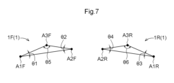
- a diagram showing the layout relationship (distance between axles, etc.) of the axles of the front-wheel drive unit and rear-wheel drive unit A diagram showing the arrangement relationship (arrangement angle) of the shafts of the front-wheel drive unit and the rear-wheel drive unit.
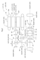
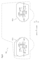
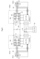
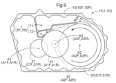
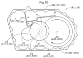
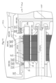
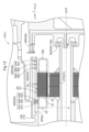
- Schematic block diagram of a system for driving and controlling a first rotating electrical machine and a second rotating electrical machine A diagram showing an example of introducing oil into the first catch tank of the front wheel drive unit in a forward rotation state. A diagram showing an example of introducing oil to the second catch tank of the rear wheel drive unit in a forward rotation state. A diagram showing an example of supplying oil to the first rotating electric machine via the first oil passage. A diagram showing an example of supplying oil to the second rotating electric machine via the second oil passage.
- the vehicle 100 of this embodiment includes a front wheel drive unit 1F that drives a pair of front wheels WF, and a rear wheel drive unit 1R that drives a pair of rear wheels WR.
- the front-wheel drive unit 1F and the rear-wheel drive unit 1R have substantially the same configuration except for details.
- a drive unit 1 that drives wheels W will be described. 1, 2 and 3 show the structure of the drive unit 1.
- FIG. 1 shows the structure of the drive unit 1.
- each member in the following description represents the direction when the drive unit 1 is assembled in the vehicle 100 (vehicle mounted state).
- Terms relating to the dimensions, arrangement direction, arrangement position, etc. of each member are concepts that include the state of having differences due to errors (errors to the extent allowable in manufacturing).
- the rotation shafts of the drive unit 1 in the present embodiment, separate shafts parallel to each other (for example, A1 (A1F or A1R), A2 (A2F or A2R), A3 (A3F or A3R), details will be described later) will be referred to as an axial direction L.
- a direction perpendicular to each of the above axes will be referred to as a "radial direction" with respect to each axis.
- the direction along the vertical direction when the drive unit 1 is attached to the vehicle 100 is defined as the “vertical direction Z.”
- the front wheel drive unit 1F has a first rotary electric machine 2F having a first rotor 21F and a driving force transmitted to a first differential input gear 51F.
- the first case 10F forms a first accommodation chamber E1F that accommodates the first rotary electric machine 2F, the first differential gear mechanism 5F, and the first transmission gear mechanism 6F.
- the first rotor 21F is arranged on a front-wheel input shaft A1F (first shaft), and the first differential input gear 51F is a front-wheel output shaft parallel to the front-wheel input shaft A1F and different from the front-wheel input shaft A1F. It is arranged on A2F (second axis).
- the rear wheel drive unit 1R includes a second rotating electric machine 2R having a second rotor 21R and a second differential gear mechanism 5R that distributes the driving force transmitted to the second differential input gear 51R to a pair of rear wheels WR. , a second transmission gear mechanism 6R for transmitting driving force between the second rotor 21R and the second differential input gear 51R, and a second case 10R.
- the second case 10R forms a second accommodation chamber E1R that accommodates the second rotary electric machine 2R, the second differential gear mechanism 5R, and the second transmission gear mechanism 6R.
- the second rotor 21R is arranged on the rear wheel input shaft A1R (third shaft), and the second differential input gear 51R is parallel to the rear wheel input shaft A1R and different from the rear wheel input shaft A1R. It is arranged on the wheel-side output shaft A2R (fourth shaft).
- the side of the front wheels WF with respect to the rear wheels WR in the vehicle longitudinal direction X is defined as the front-rear direction front side XF, and the opposite side is defined as the front-rear direction rear side XR.
- a direction orthogonal to the vehicle front-rear direction X when viewed in the vertical direction Z is defined as a vehicle width direction Y
- one side of the vehicle width direction Y is defined as a width direction first side Y1
- the other side is defined as a width direction second side. Let the side be Y2. As shown in FIG.
- the front wheel input shaft A1F (first shaft) is arranged on the front side XF in the front-rear direction with respect to the front wheel output shaft A2F (second shaft).
- the rear-wheel input shaft A1R (third shaft) is arranged rearward XR in the front-rear direction with respect to the rear-wheel output shaft A2R (fourth shaft). That is, the front-wheel drive unit 1F and the rear-wheel drive unit 1R are mounted on the vehicle 100 so that their axial positions in the longitudinal direction X of the vehicle are opposite to each other.
- the first rotor 21F is arranged on the first side Y1 in the width direction with respect to the first transmission gear mechanism 6F (the back side of the paper surface in FIG. 4).
- the second rotor 21R is arranged on the second widthwise side Y2 (the front side of the drawing in FIG. 4) with respect to the second transmission gear mechanism 6R.
- the front-wheel drive unit 1F and the rear-wheel drive unit 1R are defined by the positional relationship between the first rotating electric machine 2F and the first differential gear mechanism 5F in the vehicle width direction Y (axial direction L), and the positional relationship between the second rotating electric machine 2R and It is mounted on the vehicle 100 in a state opposite to the positional relationship with the second differential gear mechanism 5R. Then, as shown in FIG.
- a front-wheel-side first shaft distance D12F which is the distance between the front-wheel-side input shaft A1F (first shaft) and the front-wheel-side output shaft A2F (second shaft), and a rear-wheel-side
- the input shaft A1R (third shaft) and the rear wheel side output shaft A2R (fourth shaft) have the same rear wheel first center distance D12R.
- the direction of rotation of the first rotor 21F viewed from the side of the first transmission gear mechanism 6F and the direction of rotation of the second rotor 21R viewed from the side of the second transmission gear mechanism 6R are opposite to each other when the vehicle 100 is running. direction (details will be described later with reference to FIGS. 8 and 9).
- the front wheel drive unit 1F and the rear wheel drive unit 1R have substantially the same configuration except for details.
- the front-wheel drive unit 1F and the rear-wheel drive unit 1R are mounted on the vehicle 100 such that their axial positions in the longitudinal direction X of the vehicle are opposite to each other.
- the positional relationship between the first rotating electrical machine 2F and the first differential gear mechanism 5F in the direction L) and the positional relationship between the second rotating electrical machine 2R and the second differential gear mechanism 5R are opposite to each other. Installed in 100.
- the front-wheel drive unit 1F and the rear-wheel drive unit 1R are in a state in which the two drive units 1 having substantially the same configuration are in a relationship of 180° rotational symmetry with respect to the virtual axis along the vertical direction Z. It is mounted on the vehicle 100 .
- a front wheel drive unit 1F and a rear wheel drive unit 1F each including a rotating electrical machine 2 (a first rotating electrical machine 2F and a second rotating electrical machine 2R) as driving force sources for the drive unit 1 for four-wheel drive and a rear wheel drive unit 1F are provided.
- the input shaft A1 front wheel side input shaft A1F, rear wheel side input shaft A1F, rear wheel side input shaft A1F, rear wheel side input shaft A1R, rear wheel side input shaft A1R
- an output shaft A2 front wheel side output shaft A2F, rear wheel side output shaft A2R
- the differential gear mechanism 5 first differential gear mechanism 5F, second differential gear mechanism 5R
- the vehicle 100 including the drive unit 1 for four-wheel drive can be realized at low cost.
- the first rotating electric machine 2F is arranged on the front-rear direction front side XF of the front wheel output shaft A2F (second shaft), which is the axle to which the front wheels WF are connected.
- the second rotating electric machine 2R is arranged on the rear side XR in the front-rear direction of the rear wheel side output shaft A2R (fourth shaft), which is the axle to which the rear wheels WR are connected. It is easy to secure space between the axle of WR. This makes it easy to mount the high-voltage DC power supply BH and the like in the space, and to secure a vehicle compartment.
- the second rotating electric machine 2R is arranged on the front side XF in the front-rear direction of the rear wheel side output shaft A2R, there is a possibility that it will be difficult to secure the leg space of the rear seat. be.
- the drive unit 1 includes a rotating electric machine 2 having a rotor 21, a differential gear mechanism 5 for distributing the driving force transmitted to the differential input gear 51 to a pair of wheels W, the rotor 21 and the differential input gear 51. It comprises a transmission gear mechanism 6 for transmitting driving force between and a case 10 .
- the case 10 forms a device housing chamber E1 that houses the rotary electric machine 2, the differential gear mechanism 5, and the transmission gear mechanism 6. As shown in FIG.
- the rotor 21 corresponds to the first rotor 21F and the second rotor 21R
- the rotating electrical machine 2 corresponds to the first rotating electrical machine 2F and the second rotating electrical machine 2R
- the differential input gear 51 corresponds to the first differential
- the differential gear mechanism 5 corresponds to the first differential gear mechanism 5F and the second differential gear mechanism 5R
- the wheels W are the front wheels WF and the rear wheels.
- the transmission gear mechanism 6 corresponds to the first transmission gear mechanism 6F and the second transmission gear mechanism 6R
- the equipment storage chamber E1 corresponds to the first storage chamber E1F and the second storage chamber E1R.
- the rotor 21 is arranged on the input shaft A1, and the differential input gear 51 is arranged on the output shaft A2 parallel to the input shaft A1 and different from the input shaft A1.
- the input shaft A1 corresponds to the front wheel side input shaft A1F (first shaft) and the rear wheel side input shaft A1R (third shaft).
- the output shaft A2 corresponds to the front wheel output shaft A2F (second shaft) and the rear wheel output shaft A2R (fourth shaft).
- the rotating electric machine 2 is a drive source that drives a pair of wheels W.
- the transmission gear mechanism 6 that transmits driving force between the rotor 21 and the differential input gear 51 includes a rotor output gear 31 that rotates integrally with the rotor 21 and a counter gear mechanism 4. It has As will be described later, the rotor output gear 31 is arranged on the input shaft A1, and the counter gear mechanism 4 is arranged on a counter shaft A3 parallel to and different from the input shaft A1 and the output shaft A2. As will be described later, the rotor output gear 31 corresponds to a first rotor output gear 31F in the front wheel drive unit 1F and a second rotor output gear 31R in the rear wheel drive unit 1R.
- the counter gear mechanism 4 corresponds to the first counter gear mechanism 4F in the front wheel drive unit 1F and the second counter gear mechanism 4R in the rear wheel drive unit 1R.
- the counter shaft A3 corresponds to the front wheel side counter shaft A3F (fifth shaft) in the front wheel drive unit 1F and the rear wheel side counter shaft A3R (sixth shaft) in the rear wheel drive unit 1R.
- the rotating electrical machine 2 is, for example, a rotating electrical machine (Motor/Generator) that operates with multi-phase alternating current (eg, 3-phase alternating current), and can function as both a motor and a generator.
- the rotary electric machine 2 is powered by receiving power from a DC power supply (high-voltage DC power supply BH shown in FIG. 8), or supplies (regenerates) power generated by the inertial force of the vehicle 100 to the DC power supply.
- the rotary electric machine 2 is driven and controlled by a rotary electric machine control device 9 (see FIG. 8) having an inverter circuit PM that converts power between DC power and multi-phase AC power.
- the rotary electric machine control device 9 is also accommodated in the case 10.
- an inverter housing chamber E2 third housing chamber E2F, fourth housing chamber E2R
- for housing the rotary electric machine control device 9 is formed separately from the equipment housing chamber E1.
- the inverter circuit PM (power module, which will be described later) is connected to the AC rotary electric machine 2 and the DC power supply, and converts power between multiple-phase (eg, three-phase) AC and DC power.
- a high-voltage DC power supply BH as a DC power supply is composed of, for example, a secondary battery (battery) such as a nickel-metal hydride battery or a lithium-ion battery, an electric double layer capacitor, or the like.
- the rated power supply voltage of the high-voltage DC power supply BH is, for example, 200 to 400 [V].
- the inverter circuit PM is configured with a plurality of switching elements SD.
- the switching element SD includes IGBT (Insulated Gate Bipolar Transistor), power MOSFET (Metal Oxide Semiconductor Field Effect Transistor), SiC-MOSFET (Silicon Carbide - Metal Oxide Semiconductor FET), SiC-SIT (SiC - Static Induction Transistor), GaN - It is preferable to apply a power semiconductor element capable of operating at high frequencies, such as a MOSFET (Gallium Nitride - MOSFET).
- the inverter circuit PM is integrated into one power module including the freewheel diode FD.
- a DC link capacitor C smoothing capacitor for smoothing the voltage between the positive and negative electrodes (DC link voltage) is provided on the DC side of the inverter circuit PM.
- the inverter circuit PM is controlled by the inverter control device 91 (first inverter control device 91F, second inverter control device 91R).
- the inverter control device 91 is a control device higher than the inverter control device 91, and based on the speed and torque commands from the vehicle control device 92 that controls the running of the vehicle 100, the rotating electric machine 2 is controlled via the inverter circuit PM. to control.
- the inverter control device 91 is constructed with a logic circuit such as a microcomputer as a core member, and drives and controls the rotating electric machine 2 via the inverter circuit PM by current feedback control based on the detection results of the rotation sensor S1 and the current sensor S2, for example. .
- the rotation sensor S1 is a sensor such as a resolver that detects the rotation of the rotor 21 (rotational speed and rotational position (the magnetic pole position of the permanent magnet included in the rotor 21)), and the current sensor S2 detects the stator coil 25 ( (to be described later) is a sensor that detects an alternating current flowing through.
- the microcomputer and the like that make up the inverter control device 91 operate by being supplied with power from a low-voltage DC power supply BL with a lower voltage (for example, 12 to 24 [V]) than the high-voltage DC power supply BH connected to the inverter circuit PM. For this reason, the inverter control device 91 has a switching control signal (in the case of an IGBT, a gate drive signal) driving capability (for example, voltage amplitude, output current, etc., to operate a subsequent circuit) for each switching element SD.
- a drive circuit is provided that relays the The inverter control device 91 is configured by mounting the above-described microcomputer, its peripheral circuits, and circuit parts constituting a drive circuit on one or a plurality of substrates.
- the rotary electric machine control device 9 is configured as a unit including the inverter control device 91, the DC link capacitor C, and the inverter circuit PM (power module) as described above.
- the rotary electric machine control device 9 is arranged in the inverter housing chamber E2 inside the case 10, and is fixed to the case 10 by fastening members such as bolts.
- the first rotating electrical machine 2F and the second rotating electrical machine 2R are independently driven and controlled. Therefore, as the rotary electric machine control device 9, a first control device 9F that drives and controls the first rotary electric machine 2F and a second control device 9R that drives and controls the second rotary electric machine 2R are provided. Similarly, as the inverter control device 91, the first control device 9F is provided with a first inverter control device 91F, and the second control device 9R is provided with a second inverter control device 91R.
- the first inverter control device 91F and the second inverter control device 91R are configured as control devices having the same configuration.
- the first control device 9F and the second control device 9R are configured with an inverter circuit PM (power module) and a DC link capacitor C having the same configuration. That is, the first control device 9F and the second control device 9R have the same circuit configuration made up of circuit parts having the same electrical characteristics.
- the first case 10F is provided with a third housing chamber E2F that houses the first control device 9F.
- the second case 10R is provided with a fourth accommodation chamber E2R that accommodates the second control device 9R.
- the first control device 9F and the second control device 9R have the same circuit configuration with the same circuit components having the same electrical characteristics. It is easy to share the case structure with
- the first case 10F of the front wheel drive unit 1F and the second case 10R of the rear wheel drive unit 1R can be cast using a common mold.
- the front wheel drive unit 1F and the rear wheel drive unit 1R share part or all of the internal structure. easy to configure.
- the front wheel drive unit 1F and the rear wheel drive unit 1R can be easily configured by sharing part or all of the case structure.
- the device housing E1 and the inverter housing E2 are integrally formed. That is, the case 10 has a main body portion integrally formed with a device housing chamber E1 for housing the rotating electrical machine 2 and the like and an inverter housing chamber E2 for housing the rotating electrical machine control device 9 therein. ing.
- integrally formed refers to a unitary member formed of a common material, eg, as a single die casting.
- the rotating electrical machine 2 has a stator 23 fixed to the case 10 or the like, and a rotor 21 rotatably supported radially inward of the stator 23 .
- the stator 23 includes a stator core 24 and stator coils 25 wound around the stator core 24
- the rotor 21 includes a rotor core 22 and permanent magnets 26 arranged on the rotor core 22 .
- the stator 23 of the first rotating electrical machine 2F is referred to as the first stator 23F.
- the stator 23 of the second rotating electrical machine 2R is called a second stator 23R.
- a rotor 21 of the rotating electric machine 2 is connected to a rotor shaft 20 that rotates integrally with the rotor 21 .
- a rotor connecting shaft 30 is connected to the rotor shaft 20 so as to rotate together with the rotor shaft 20 .
- the rotor shaft 20 is rotatably supported by the case 10 via a rotor bearing B2, and the rotor coupling shaft 30 is rotatably supported by the case 10 via an input bearing B3.
- a rotor output gear 31 is provided on the rotor connecting shaft 30 so as to rotate together with the rotor connecting shaft 30 . That is, the drive unit 1 includes a power input mechanism 3 having a rotor connecting shaft 30 and a rotor output gear 31 .
- the rotor shaft 20 of the rotary electric machine 2 is supported by the first rotor bearing B21 on the opposite side of the rotor 21 from the rotor connecting shaft 30 (rotor output gear 31) in the axial direction L, and is axially connected to the rotor 21.
- the rotor connecting shaft 30 (rotor output gear 31) side in the direction L is supported by the second rotor bearing B22.
- the rotor output gear 31 meshes with the first counter gear 41 of the counter gear mechanism 4 as will be described later. That is, the rotor output gear 31 functions as a part of the transmission gear mechanism 6 , rotates integrally with the rotor 21 , and transmits the driving force of the rotary electric machine 2 to the counter gear mechanism 4 .
- the front wheel drive unit 1F When distinguishing bearings between the front wheel drive unit 1F and the rear wheel drive unit 1R, the front wheel drive unit 1F is provided with a front wheel side rotor bearing B2F as the rotor bearing B2 and a front wheel side input bearing B3F as the input bearing B3,
- the rear wheel drive unit 1R is provided with a rear wheel side rotor bearing B2R as the rotor bearing B2 and a rear wheel side input bearing B3R as the input bearing B3.
- the power input mechanism 3 and the rotor output gear 31 the front wheel drive unit 1F is provided with a first power input mechanism 3F and a first rotor output gear 31F
- the rear wheel drive unit 1R is provided with a second power input mechanism 3R. and a second rotor output gear 31R.
- the differential gear mechanism 5 is arranged on the output shaft A2 and distributes the driving force transmitted from the rotating electrical machine 2 side to the pair of wheels W.
- the differential gear mechanism 5 includes a plurality of bevel gears (pinion gear 53, differential output gear 54) that mesh with each other, and a differential case 52 that accommodates the plurality of bevel gears.
- the differential case 52 is rotatably supported by the case 10 through a differential bearing B5.
- the differential gear mechanism 5 is arranged along the radial direction of the output shaft A2 and integrated with the differential input gear 51 to transmit the rotation and torque input to the differential input gear 51 from the rotary electric machine 2 side.
- the power is distributed and transmitted to a pair of output members 70 via a pair of differential output gears 54 meshing with a pinion gear 53 rotatably supported on a pinion shaft 55 that rotates dynamically.
- the output member 70 is rotatably supported by the case 10 via an output bearing B7.
- the front wheel drive unit 1F includes a first differential gear mechanism 5F having a first differential input gear 51F on the front wheel side output shaft A2F
- the rear-wheel drive unit 1R includes a second differential gear mechanism 5R having a second differential input gear 51R on the rear-wheel output shaft A2R.
- the counter gear mechanism 4 is arranged on the counter shaft A3, and drives and connects the rotating electric machine 2 and the differential gear mechanism 5 (differential input gear 51) via the rotor output gear 31.
- the counter connecting shaft 40 is rotatably supported by the case 10 via a counter bearing B4.
- the counter gear mechanism 4 includes a first counter gear 41 and a second counter gear 42 that are connected by a counter connecting shaft 40 .
- the first counter gear 41 meshes with the rotor output gear 31
- the second counter gear 42 connected to the first counter gear 41 by the counter connecting shaft 40 meshes with the differential input gear 51 . That is, the counter gear mechanism 4 functions as a part of the transmission gear mechanism 6 and transmits the driving force transmitted from the rotary electric machine 2 via the rotor output gear 31 to the differential input gear 51 .
- the front wheel drive unit 1F includes, as the counter gear mechanism 4, a front wheel side first counter gear 41F (first gear) and a front wheel side second counter gear 42F (second gear). 2 gears) and a first counter gear mechanism 4F.
- the rear wheel drive unit 1R includes, as the counter gear mechanism 4, a second counter gear including a rear wheel first counter gear 41R (third gear) and a rear wheel second counter gear 42R (fourth gear). It has mechanism 4R.
- the first transmission gear mechanism 6F of the front wheel drive unit 1F includes a first rotor output gear 31F that rotates integrally with the first rotor 21F, and a first counter gear mechanism 4F.
- the first counter gear mechanism 4F includes a front wheel side first counter gear 41F (first gear) and a front wheel side second counter gear 42F (second gear) that rotates integrally with the front wheel side first counter gear 41F (first gear). gear).
- the front-wheel-side first counter gear 41F (first gear) and the first rotor output gear 31F are meshed, and the front-wheel-side second counter gear 42F (second gear) is meshed with the first differential input gear 51F. .
- the second transmission gear mechanism 6R includes a second rotor output gear 31R that rotates integrally with the second rotor 21R, and a second counter gear mechanism 4R.
- the second counter gear mechanism 4R includes a first rear wheel counter gear 41R (third gear) and a second rear wheel counter gear 42R that rotates integrally with the first rear wheel counter gear 41R (third gear). (fourth gear). Then, the rear wheel side first counter gear 41R (third gear) and the second rotor output gear 31R are meshed, and the rear wheel side second counter gear 42R (fourth gear) and the second differential input gear 51R are meshed. ing.
- the front wheel drive unit 1F and the rear wheel drive unit 1R have a positional relationship between the first rotating electric machine 2F and the first differential gear mechanism 5F in the vehicle width direction Y (axial direction L) and the second rotation
- the electric machine 2R and the second differential gear mechanism 5R are mounted on the vehicle 100 so that their positional relationship is reversed. That is, the front-wheel drive unit 1F and the rear-wheel drive unit 1R are in a state in which the two drive units 1 having substantially the same configuration are in a relationship of 180° rotational symmetry with respect to the virtual axis along the vertical direction Z. It is mounted on the vehicle 100 .
- the counter gear mechanism 4 is arranged on the side where the front wheel side second counter gear 42F (second gear) is arranged with respect to the front wheel side first counter gear 41F (first gear) in the vehicle width direction Y, and on the side where the front wheel side second counter gear 42F (second gear) is arranged.
- the side on which the rear wheel side second counter gear 42R (fourth gear) is arranged is the opposite side to the side first counter gear 41R (third gear).
- the front-wheel drive unit 1F and the rear-wheel drive unit 1R are two drive units 1 having substantially the same configuration, with the virtual axis along the vertical direction Z as the symmetrical axis. They are mounted on the vehicle 100 in a rotationally symmetrical relationship. For this reason, as described above with reference to FIG. The distance D12R between the input shaft A1R (third shaft) and the rear wheel side output shaft A2R (fourth shaft) is the same. Further, as shown in FIG.
- the front wheel first angle ⁇ f1 which is the angle between the horizontal plane and the plane including the front wheel input shaft A1F (first shaft) and the front wheel output shaft A2F (second shaft)
- the rear wheel side first angle ⁇ r1 which is the angle between the horizontal plane and the plane including the side input shaft A1R (third shaft) and the rear wheel side output shaft A2R (fourth shaft)
- the same angle means that the magnitude (absolute value) of the angle is the same regardless of the direction.
- the first transmission gear mechanism 6F has a front wheel counter shaft A3F (fifth shaft) parallel to and different from the front wheel input shaft A1F (first shaft) and the front wheel output shaft A2F (second shaft). ) is provided with a first counter gear mechanism 4F disposed above.
- the second transmission gear mechanism 6R has a rear wheel counter shaft A3R (sixth shaft) parallel to and different from the rear wheel input shaft A1R (third shaft) and the rear wheel output shaft A2R (fourth shaft). ) is provided with a second counter gear mechanism 4R disposed above. As shown in FIG.
- the distances between the front wheel input shaft A1F (first shaft), the front wheel output shaft A2F (second shaft), and the front wheel counter shaft A3F (fifth shaft) are D12F, D23F. , D13F", and the inter-axle distance "D12R, D23R, D13R" are the same.
- the front wheel side first center distance D12F and the rear wheel side first center distance D12R are the same, and the front wheel side output shaft A2F (second shaft) and front wheel side counter shaft A3F (fifth shaft) are the same. ), and the distance between the rear wheel output shaft A2R (fourth shaft) and the rear wheel counter shaft A3R (sixth shaft), which is the rear wheel It is the same as the side second center distance D23R.
- the front wheel side third shaft distance D13F which is the distance between the front wheel side input shaft A1F (first shaft) and the front wheel side counter shaft A3F (fifth shaft), and the rear wheel side input shaft A1R (third shaft) ) and the rear-wheel-side third center-to-center distance D13R, which is the center-to-center distance between the rear-wheel-side counter shaft A3R (sixth shaft), have the same length. That is, in the present embodiment, the positional relationship between the shaft (input shaft A1) on which the rotary electric machine 2 is arranged and the shaft (output shaft A2) on which the differential gear mechanism 5 is arranged is common.
- the front wheel side first angle ⁇ f1 and the rear wheel side first angle ⁇ r1 are the same. are the same.
- the front-wheel second angle ⁇ f2 which is the angle between a plane including the front-wheel-side input shaft A1F (first axis) and the front-wheel-side counter shaft A3F (fifth axis) and the horizontal plane
- the rear-wheel-side input shaft The rear-wheel-side second angle ⁇ r2, which is the angle between the horizontal plane and the plane including A1R (third axis) and rear-wheel-side counter shaft A3R (sixth axis), is the same.
- the positional relationship between the rotating electrical machine 2 and the counter gear mechanism 4 is common between the front wheel drive unit 1F and the rear wheel drive unit 1R. It is easy to share the internal structure of the drive unit 1F and the rear wheel drive unit 1R.
- the first included angle ⁇ 1 in the front wheel drive unit 1F and the third included angle ⁇ 3 in the rear wheel drive unit 1R are the same, and the second included angle ⁇ 3 in the front wheel drive unit 1F
- the included angle ⁇ 2 is the same as the fourth included angle ⁇ 4 in the rear wheel drive unit 1R
- the fifth included angle ⁇ 5 in the front wheel drive unit 1F is the same as the sixth included angle ⁇ 6 in the rear wheel drive unit 1R.
- the first included angle ⁇ 1 is defined by a plane including the front wheel input shaft A1F (first shaft) and the front wheel output shaft A2F (second shaft), the front wheel input shaft A1F (first shaft) and the front wheel counter shaft A3F
- the third included angle ⁇ 3 is the angle between a plane containing the rear wheel input shaft A1R (third shaft) and the rear wheel output shaft A2R (fourth shaft) and a plane containing the rear wheel input shaft A1R (third shaft) and the rear wheel output shaft A2R (fourth shaft). It is the angle between the plane including the wheel side input shaft A1R (third axis) and the rear wheel side counter shaft A3R (sixth axis).
- the second included angle ⁇ 2 is defined by a plane including the front wheel output shaft A2F (second shaft) and the front wheel input shaft A1F (first shaft), a front wheel output shaft A2F (second shaft) and the front wheel counter shaft.
- the fourth included angle ⁇ 4 is the angle between the plane containing the rear wheel output shaft A2R (fourth shaft) and the rear wheel input shaft A1R (third shaft). , and a plane including the rear wheel side output shaft A2R (fourth shaft) and the rear wheel side counter shaft A3R (sixth shaft).
- the fifth included angle ⁇ 5 is defined by a plane including the front wheel side counter shaft A3F (fifth shaft) and the front wheel side input shaft A1F (first shaft), the front wheel side counter shaft A3F (fifth shaft) and the front wheel side output shaft.
- the sixth included angle ⁇ 6 is the angle between the plane containing the rear wheel side counter shaft A3R (sixth shaft) and the rear wheel side input shaft A1R (third shaft). , and a plane including the rear-wheel-side counter shaft A3R (sixth shaft) and the rear-wheel-side output shaft A2R (fourth shaft).
- the inverter housing E2 in which the rotating electric machine control device 9 is housed is arranged above the equipment housing E1 in the vertical direction Z so as to overlap with the rotating electric machine 2 when viewed in the vertical direction. It is Therefore, even if the front wheel drive unit 1F, the high voltage DC power supply BH, and the rear wheel drive unit 1R are arranged in the longitudinal direction X of the vehicle as shown in FIG. In addition to being electrically connected, the rear wheel drive unit 1R and the high-voltage DC power source BH can also be appropriately electrically connected.
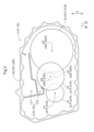
- the drive unit 1 is equipped with an oil pump (not shown), which supplies lubricating and cooling oil to the rotary electric machine 2, the transmission gear mechanism 6, the differential gear mechanism 5, and the bearings that support them. are supplying. Further, some of them are also supplied with oil that is raked up by gears housed inside the case 10 . Inside the case 10, particularly in the lower portion of the equipment housing chamber E1, an oil reservoir is formed in which the oil used for lubrication and cooling drops and is stored. A gear (for example, the differential input gear 51) provided in the drive unit 1 rakes up the oil accumulated in the oil reservoir. The raked up oil is directly supplied to a lubrication target location such as a bearing and is stored in a catch tank 7 (see FIG.
- the drive unit 1 is provided with an upper catch tank 71 formed relatively upward Z1 in the vertical direction Z and a lower catch tank 72 formed relatively downward Z1. It is The upper catch tank 71 and the lower catch tank 72 communicate with each other, and are configured so that oil stored in the upper catch tank 71 can be supplied to the lower catch tank 72 through an orifice. Also, the oil stored in the upper catch tank 71 and the lower catch tank 72 is supplied to each part to be supplied by the orifice.
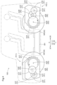
- the front-wheel drive unit 1F has a first differential input gear 51F and a first transmission gear mechanism 6F, in which oil raked up by the rotation of gears constituting the first transmission gear mechanism 6F is stored. It has 1 catch tank 7F. Further, the rear wheel drive unit 1R is provided with a second catch tank 7R that stores oil scraped up by the rotation of the gears that constitute the second differential input gear 51R and the second transmission gear mechanism 6R.
- the state in which the front wheels WF and the rear wheels WR rotate in the forward direction of the vehicle 100 is defined as the forward rotation state
- the state in which the vehicle 100 rotates in the reverse direction is defined as the reverse rotation state.
- FIG. 9 shows an example of how oil is introduced into the first catch tank 7F of the front wheel drive unit 1F in the forward rotation state.
- FIG. 10 shows an example of introducing oil into the second catch tank 7R of the rear wheel drive unit 1R in the normal rotation state. From a different point of view, it can be said that FIG. 9 shows an example of introducing oil into the second catch tank 7R of the rear wheel drive unit 1R in reverse rotation, and FIG. It can be said that this shows an example of introducing oil into the first catch tank 7F.
- the first catch tank 7F is configured to store oil that is raked up by the first differential input gear 51F when the front wheels WF are in the normal rotation state.
- the oil scraped up by the large-diameter first differential input gear 51F easily reaches the upper catch tank 71, and the upper catch tank 71 is sufficiently supplied with oil.
- the second catch tank 7R is configured to operate as shown in FIG. 1 counter gear 41R and the rear-wheel-side second counter gear 42R) are stored. Specifically, the oil scraped up mainly by the second differential input gear 51R is further displaced by the rear wheel side second counter gear 42R and the rear wheel side first counter gear 41R that mesh with the second differential input gear 51R. It is raked up and led to the second catch tank 7R. Since the direction of rotation of the large-diameter second differential input gear 51R is opposite to that of the front wheel drive unit 1F, the oil that is directly pumped up from the second differential input gear 51R into the upper catch tank 71 is the front wheel drive unit 1F. less than However, by cooperating with the gears of the counter gear mechanism 4 , the oil can be led to at least the lower stage catch tank 72 . The bottom of the upper catch tank 71 is not formed above the first counter gear 41 Z1. Also the oil is led.
- the first catch tank 7F operates as shown in FIG.
- the counter gear 41F and the front-wheel-side second counter gear 42F are configured to store the oil that is raked up. Specifically, the oil mainly raked up by the first differential input gear 51F is further raked up by the front wheel side second counter gear 42F and the front wheel side first counter gear 41F that mesh with the first differential input gear 51F. and guided to the first catch tank 7F.
- the second catch tank 7R is configured to store the oil that is raked up by the second differential input gear 51R when the rear wheel WR is in the reverse rotation state, as shown in FIG. The details of each are as described above, taking the forward rotation state as an example, and detailed description thereof will be omitted.
- the first catch tank 7F is scraped by at least one of the gears forming the first differential input gear 51F and the first transmission gear mechanism 6F in both forward and reverse rotation of the front wheels WF. It is configured to store the raised oil. Further, the second catch tank 7R is raked up by at least one of the gears forming the second differential input gear 51R and the second transmission gear mechanism 6R regardless of whether the rear wheel WR is in the forward rotation state or the reverse rotation state. It is configured so that the oil that has been collected is stored.
- the drive unit 1 is equipped with an oil pump (not shown), which supplies the rotary electric machine 2, the transmission gear mechanism 6, the differential gear mechanism 5, and their bearings with oil for lubrication and cooling. of oil can be supplied.
- the case 10 is formed integrally with the case 10 or by attaching a separate member to the case 10 to form an oil passage through which oil from the oil pump flows.
- the drive unit 1 extends along the axial direction L and is arranged to face the outer peripheral surface 2a of the rotating electric machine 2 (the outer peripheral surface of the stator core 24).
- An oil passage forming portion 80 is provided in which an oil passage 8 through which oil flows is formed. Specifically, as shown in FIGS.
- the front wheel drive unit 1F extends along the axial direction L and is arranged to face the outer peripheral surface 2a of the first rotating electrical machine 2F.
- a first oil passage formation portion 80F is provided in which a first oil passage 8F through which oil flows is formed.
- the rear wheel drive unit 1R extends along the axial direction L and is arranged to face the outer peripheral surface 2a of the second rotating electric machine 2R. It has a second oil passage formation portion 80R in which a second oil passage 8R is formed.
- the oil passage forming portion 80 is formed with a plurality of oil supply holes 89 communicating with the oil passage 8 and opening toward the rotary electric machine 2 .
- the first oil passage formation portion 80F includes a first oil supply passage communicating with the first oil passage 8F and opening toward the first rotating electric machine 2F.
- a plurality of holes 89F are formed.
- the second oil passage formation portion 80R has a second oil supply hole 89R that communicates with the second oil passage 8R and opens toward the second rotating electric machine 2R. Multiple are formed.
- the first case 10F and the second case 10R are preferably cast using a common mold.
- the first oil passage forming portion 80F and the second oil passage forming portion 80R may be formed at different positions.
- the vehicle 100 is configured to be capable of two-wheel drive using the front-wheel drive unit 1F during normal running, and four-wheel drive using the driving force of the rear-wheel drive unit 1R during specific running such as on snowy roads.
- the specifications of the first rotating electrical machine 2F mounted on the front wheel drive unit 1F and the second rotating electrical machine 2R mounted on the rear wheel drive unit 1R need not be the same.
- the cost of the second rotating electrical machine 2R can be reduced, and the cost of the vehicle 100 can be reduced.
- the front wheel drive unit 1F and the rear wheel drive unit 1R are desirable.
- the axial length of the second rotating electrical machine 2R is set to be smaller than that of the first rotating electrical machine 2F. can be shortened. That is, it is conceivable to shorten the axial length of the rotary electric machine 2 by reducing the number of laminations of the rotor core 22 and the stator core 24 that are configured by laminating a plurality of electromagnetic steel sheets in the axial direction.
- the positions in the axial direction L of the coil end portions 25e of the stator coils 25 projecting from the stator core 24 to both sides in the axial direction L are different between the first rotating electrical machine 2F and the second rotating electrical machine 2R.
- stator coil 25 In the rotating electrical machine 2 that serves as the drive source for the wheels W, the current flowing through the stator coil 25 is large, and the electrical resistance of the stator coil 25 tends to generate a large amount of heat.
- the stator coil 25 is wound around the stator core 24. At the end of the stator 23 in the axial direction L, the bent portion of the wound stator coil 25 protrudes from the stator core 24 in the axial direction L. 25e is formed. Since the stator coil 25 also passes through the inside of the stator core 24, the stator coil 25 is often cooled by applying oil as a coolant to the coil end portion 25e. Therefore, some of the oil supply holes 89 communicating with the oil passage 8 and opening toward the rotary electric machine 2 are provided so as to supply oil to the coil end portions 25e.
- one side of the axial direction L in this example, the rotor 21 is positioned relative to the rotor output gear 31.
- the arranged side is defined as an axial first side L1
- the other side in the axial direction L is defined as an axial second side L2.
- the dimension in the axial direction L is different between the first rotating electrical machine 2F and the second rotating electrical machine 2R.
- the end P on the first axial side L1 of the first rotating electrical machine 2F and the end P on the first axial side L1 of the second rotating electrical machine 2R are at the same position. Therefore, the position of the coil end portion 25e on the first side L1 in the axial direction is common between the first rotating electrical machine 2F and the second rotating electrical machine 2R. Therefore, the oil supply holes 89 (the oil supply holes 89 indicated by reference numerals 81, 82, and 83) for supplying oil to the coil end portions 25e on the axial first side L1 are arranged between the first rotating electric machine 2F and the second rotating electric machine 2F. It is formed at a position common to 2R.
- the second oil supply holes 89R indicated by reference numerals 81R, 82R, and 83R for supplying oil to the coil end portions 25e on the direction first side L1 are formed at the same positions in the axial direction L.
- the front wheel drive unit 1F is formed with first oil supply holes 89F indicated by reference numerals 84F and 85F for supplying cooling oil to the stator core 24 of the first rotating electric machine 2F. . Further, the front wheel drive unit 1F is formed with first oil supply holes 89F indicated by reference numerals 86F, 87F, and 88F for supplying oil to the coil end portions 25e on the axial second side L2 of the first rotary electric machine 2F. It is In the front wheel drive unit 1F, the coil end portion 25e on the axial second side L2 and the rotor bearing B2 (first rotor bearing B21) on the axial second side L2 overlap when viewed in the vertical direction. Therefore, the rotor bearing B2 can also be lubricated by dropping the oil that has cooled the coil end portion 25e.
- the rear wheel drive unit 1R is formed with a second oil supply hole 89R indicated by reference numeral 84R for supplying cooling oil to the stator core 24 of the second rotating electric machine 2R. Further, the rear wheel drive unit 1R has second oil supply holes 89R indicated by reference numerals 85R, 86R, and 87R for supplying oil to the coil end portions 25e on the axial second side L2 of the second rotating electric machine 2R. formed. Further, the rear wheel drive unit 1R is also formed with a second oil supply hole 89R indicated by reference numeral 88R for supplying lubricating oil to the rotor bearing B2 (first rotor bearing B21) on the axial second side L2.
- the second rotating electrical machine 2R whose length in the axial direction L is shorter than that of the first rotating electrical machine 2F, if the arrangement position of the rotor bearing B2 is made common for the purpose of sharing the structure, the second side in the axial direction when viewed in the vertical direction
- the coil end portion 25e at L2 and the rotor bearing B2 (first rotor bearing B21) at the axial second side L2 do not overlap. Since the oil that cools the coil end portion 25e does not drop to the rotor bearing B2, a reference numeral 88R is provided above the rotor bearing B2 (a position facing the rotor bearing B2 in the radial direction with respect to the input shaft A1). It is preferable that a second oil supply hole 89R indicated by is formed.
- the front wheel drive unit 1F and the rear wheel drive unit 1R share a part or all of the case structure, for example, the first Even if the dimensions in the axial direction L of the rotating electrical machine 2F and the second rotating electrical machine 2R are different, it is possible to provide a structure that facilitates supplying oil to appropriate positions according to the dimensions of the respective rotating electrical machines 2 . That is, according to the present embodiment, it is possible to realize the vehicle 100 equipped with a drive unit for four-wheel drive at low cost while sharing part of the internal structure and part of the case structure.
- the oil supply hole 89 can be formed, for example, by performing additional work on the cast case 10 . As described above, by making the position of the oil supply hole 89 adjustable, it is possible to configure the drive unit 1 according to the required specifications of the vehicle 100 while using the case 10 in common.
- the drive unit 1 having the three-axis configuration of the input shaft A1, the output shaft A2, and the counter shaft A3 has been illustrated and explained.
- the configuration is not limited to such a configuration, and the drive unit 1 may have a two-axis configuration or a configuration with four or more axes.
- first case 10F and the second case 10R are cast using a common mold.
- first case 10F and the second case 10R may be cast using molds at least partially different from each other.
- the front wheel drive unit 1F and the rear wheel drive unit 1R have the same distance between the input shaft A1, the output shaft A2, and the counter shaft A3.
- the arrangement position of the counter shaft A3 may be different between the front wheel drive unit 1F and the rear wheel drive unit 1R.
- the first included angle ⁇ 1 and the third included angle ⁇ 3 are the same, and the second included angle ⁇ 2 and the fourth included angle ⁇ 4 are the same.
- the fifth included angle ⁇ 5 and the sixth included angle ⁇ 6 may not be the same.
- the front wheel drive unit 1F and the rear wheel drive unit 1R are provided with the transmission gear mechanism 6 having the same configuration, and the first transmission gear mechanism 6F of the front wheel drive unit 1F and the second transmission gear mechanism 6F of the rear wheel drive unit 1R are provided.
- a configuration in which the transmission gear mechanism 6R and the transmission gear mechanism 6R are arranged rotationally symmetrically by rotating 180 degrees with respect to an imaginary axis of symmetry along the vertical direction Z has been described as an example.
- the transmission gear mechanism 6 may have different configurations between the front wheel drive unit 1F and the rear wheel drive unit 1R.
- the first control device 9F and the second control device 9R have been described by exemplifying the form provided with the same circuit configuration composed of circuit components having the same electrical characteristics. However, this does not prevent the first control device 9F and the second control device 9R from having different circuit configurations composed of circuit components with different electrical characteristics. Also in this case, it is preferable to house the first control device 9F and the second control device 9R in the inverter housing E2 having the same configuration.
- the drive unit 1 includes the catch tank 7 as an example. However, the drive unit 1 does not have to include the catch tank 7 .
- each part in the drive unit 1 may be cooled or lubricated by oil supplied from an oil pump or the like.
- the first rotating electrical machine 2F and the second rotating electrical machine 2R have different lengths in the axial direction L, as an example.
- the first rotating electrical machine 2F and the second rotating electrical machine 2R may be rotating electrical machines having the same length in the axial direction L.
- the oil supply holes 89 may be formed at the same position in the axial direction L.
- the front-wheel first angle ⁇ f1 which is the angle between a plane including the front-wheel input shaft A1F and the front-wheel output shaft A2F and the horizontal plane
- the rear-wheel input shaft A1R and the rear-wheel output shaft A2R and the rear-wheel-side first angle .theta.r1 which is the angle between the horizontal plane and the plane containing the .
- this does not prevent the front wheel side first angle ⁇ f1 and the rear wheel side first angle ⁇ r1 from being different angles.
- the front wheel drive unit 1F and the rear wheel drive unit 1R may be mounted at different angles with respect to the horizontal plane (horizontal plane of the vehicle body). The angle is different from ⁇ r1.
- the front-wheel second angle ⁇ f2 which is the angle between a plane including the front-wheel input shaft A1F and the front-wheel counter shaft A3F and the horizontal plane, the rear-wheel input shaft A1R and the rear-wheel counter shaft A3R , and the rear-wheel-side second angle .theta.r2, which is the angle between the horizontal plane and the plane containing the .
- this does not prevent the front wheel side second angle ⁇ f2 and the rear wheel side second angle ⁇ r2 from being different angles.
- a vehicle (100) comprising a front wheel drive unit (1F) that drives a pair of front wheels (WF) and a rear wheel drive unit (1R) that drives a pair of rear wheels (WR),
- the front wheel drive unit (1F) a first rotating electrical machine (2F) having a first rotor (21F); a first differential gear mechanism (5F) that distributes the driving force transmitted to the first differential input gear (51F) to the pair of front wheels (WF); a first transmission gear mechanism (6F) for transmitting driving force between the first rotor (21F) and the first differential input gear (51F); a first case (10F) forming a first housing chamber (E1F) housing the first rotating electric machine (2F), the first differential gear mechanism (5F), and the first transmission gear mechanism (6F); , and Said first rotor (21F) is arranged on a first axis (A1F) and said first differential input gear (51F) is parallel to said first axis (A1F) and different from said first axis
- the side of the front wheel (WF) with respect to the rear wheel (WR) in the vehicle longitudinal direction (X) is defined as the front-rear direction front side (XF), and the opposite side is defined as the front-rear direction rear side (XR),
- One side in the vehicle width direction (Y) is defined as a width direction first side (Y1), and the other side is defined as a width direction second side (Y2),
- the first shaft (A1F) is arranged on the front-rear direction front side (XF) with respect to the second shaft (A2F), and the first rotor (21F) is arranged on the front side (XF) of the second shaft (A2F).
- a distance (D12F) between the first axis (A1F) and the second axis (A2F) and a distance (D12R) between the third axis (A1R) and the fourth axis (A2R) are is the same and
- the direction of rotation of the first rotor (21F) viewed from the side of the first transmission gear mechanism (6F) and the direction of rotation of the second rotor (21R) viewed from the side of the second transmission gear mechanism (6R) is the opposite direction when the vehicle (100) is running.
- a vehicle ( 100), in the case (10) of these drive units (1) there are two shafts (A1) on which the rotating electric machine (2) is arranged and a shaft (A2) on which the differential gear mechanism (5) is arranged.
- the positional relationship of the axes is common. Therefore, the front wheel drive unit (1F) and the rear wheel drive unit (1R) can easily share part or all of the internal structure and part or all of the case structure. As a result, it is easy to reduce the number of types of parts of the drive unit (1) for four-wheel drive and to reduce the cost.
- the first rotating electrical machine (2F) is arranged on the front-rear direction front side (XF) of the second shaft (A2F), which is the axle to which the front wheels (WF) are connected, and the rear wheels (WF) are connected.
- the second rotating electric machine (2R) is arranged on the rear side (XR) in the front-rear direction of the fourth shaft (A2R), which is the axle to which the rear wheels (WR) are connected. It is easy to secure a space between the axle of the front wheel (WF) and the axle of the rear wheel (WR).
- the first transmission gear mechanism (6F) is arranged on a fifth axis (A3F) parallel to and different from the first axis (A1F) and the second axis (A2F).
- the second transmission gear mechanism (6R) has a sixth axis parallel to and different from the third axis (A1R) and the fourth axis (A2R) ( A3R) with a second counter gear mechanism (4R) disposed on the first axis (A1F), the second axis (A2F) and the fifth axis (A3F) with a mutual inter-axis distance (D12F , D13F, D23F) and the inter-axis distances (D12F, D13F, D23F) among the third axis (A1R), the fourth axis (A2R) and the sixth axis (A3R) are the same. preferred.
- the positional relationship is also the same. Therefore, the front wheel drive unit (1F) and the rear wheel drive unit (1R) can easily share part or all of the internal structure and part or all of the case structure.
- the vehicle (100) is an angle ( ⁇ 1) between a plane containing the first axis (A1F) and the second axis (A2F) and a plane containing the first axis (A1F) and the fifth axis (A3F); an angle ( ⁇ 3) between a plane containing the third axis (A1R) and the fourth axis (A2R) and a plane containing the third axis (A1R) and the sixth axis (A3R) is the same, and and, an angle ( ⁇ 2) between a plane containing the second axis (A2F) and the first axis (A1F) and a plane containing the second axis (A2F) and the fifth axis (A3F); an angle ( ⁇ 4) between a plane containing the fourth axis (A2R) and the third axis (A1R) and a plane containing the fourth axis (A2R) and the sixth axis (A3R) is the same;
- the positional relationship among the rotary electric machine (2), the differential gear mechanism (5) and the counter gear mechanism (4) is common to the front wheel drive unit (1F) and the rear wheel drive unit (1R). Therefore, it is easy to share the internal structure of the front wheel drive unit (1F) and the rear wheel drive unit (1R).
- the first transmission gear mechanism (6F) includes a first rotor output gear (31F) rotating integrally with the first rotor (21F) and the first counter gear mechanism (4F).
- the first counter gear mechanism (4F) includes a first gear (41F) and a second gear (42F) that rotates integrally with the first gear (41F)
- the 1 gear (41F) meshes with the first rotor output gear (31F)
- the second transmission gear mechanism (6R) includes a second rotor output gear (31R) that rotates integrally with the second rotor (21R), and the second counter gear mechanism (4R).
- a two-counter gear mechanism (4R) includes a third gear (41R) and a fourth gear (42R) that rotates integrally with the third gear (41R).
- 2-rotor output gear (31R) meshes, said fourth gear (42R) meshes with said second differential input gear (51R),
- the side where the second gear (42F) is arranged with respect to the first gear (41F) and the side where the fourth gear (42R) is arranged with respect to the third gear (41R) is preferably opposite to the side on which the is arranged.
- the front wheel drive unit (1F) and the rear wheel drive unit (1R) have a common internal structure. easy to convert.
- the vehicle (100) includes a first control device (9F) that drives and controls the first rotating electrical machine (2F) and a second control device (9R) that drives and controls the second rotating electrical machine (2R).
- the first control device (9F) and the second control device (9R) have the same circuit configuration made up of circuit parts having the same electrical characteristics, and the first case (10F) has the first 1 controller (9F), and the second case (10R) preferably includes a fourth storage chamber (E2R) that accommodates the second controller (9R). be.
- the first control device (9F) and the second control device (9R) have a common configuration having the same circuit configuration made up of circuit parts having the same electrical characteristics, It is easy to share the case structure of the front wheel drive unit (1F) and the rear wheel drive unit (1R).
- the vehicle (100) is The front wheel drive unit (1F) is provided with a first catch tank ( 7F), A second catch tank in which the rear wheel drive unit (1R) stores oil scraped up by the rotation of the gears constituting the second differential input gear (51R) and the second transmission gear mechanism (6R). (7R), A state in which the front wheels (WF) and the rear wheels (WR) rotate in the forward direction of the vehicle (100) is defined as a forward rotation state, and a state in which the vehicle (100) rotates in the reverse direction. as the reversed state, The first catch tank (7F) constitutes the first differential input gear (51F) and the first transmission gear mechanism (6F) regardless of whether the front wheel (WF) is in a forward rotation state or a reverse rotation state.
- the second catch tank (7R) operates the second differential input gear (51R) and the second transmission gear mechanism (6R) in both forward and reverse rotation states of the rear wheel (WR). It is preferable that the oil raked up by at least one of the constituent gears is stored.
- the catch tank (7 (7F, 7R)) is Oil can be stored properly. Then, the oil can be appropriately supplied to the necessary locations through the catch tanks (7 (7F, 7R)). Therefore, it is easy to share the front wheel drive unit (1F) and the rear wheel drive unit (1R).
- the vehicle (100) is A direction parallel to the first axis (A1F) in the front wheel drive unit (1F) and a direction parallel to the third axis (A1R) in the rear wheel drive unit (1R) are axial directions (L), One side in the axial direction (L) is defined as an axial direction first side (L1), and the other side in the axial direction (L) is defined as an axial direction second side (L2),
- the front wheel drive unit (1F) extends along the axial direction (L) and is arranged to face the outer peripheral surface of the first rotating electrical machine (2F), and a first oil circulating therein.
- the rear wheel drive unit (1R) extends along the axial direction (L) and is arranged to face the outer peripheral surface of the second rotating electric machine (2R), and a second rotating electric machine (1R) through which oil flows.
- the second oil passage forming portion (80R) has a plurality of second oil supply holes (89R) communicating with the second oil passage (8R) and opening toward the second rotating electric machine (2R).
- the dimension in the axial direction (L) of the first rotating electrical machine (2F) and the second rotating electrical machine (2R) are different, Positional relationship of the plurality of first oil supply holes (89F) with reference to the end of the first rotating electrical machine (2F) on the first side (L1) in the axial direction; It is preferable that the positional relationship of the plurality of second oil supply holes (89R) with respect to the end portion on the axial direction first side (L1) is different from each other.
- the front wheel drive unit (1F) and the rear wheel drive unit (1R) can Even if the dimensions in the axial direction (L) of the first rotating electrical machine (2F) and the second rotating electrical machine (2R) are different, the respective rotating electrical machines (2 (2F, 2R)) can be configured to easily supply oil to an appropriate position. That is, according to this configuration, a vehicle (100) equipped with a drive unit (1 (1F, 1R)) for four-wheel drive at low cost while sharing part of the internal structure and part of the case structure. ) can be realized.
- the vehicle (100) has an angle ( ⁇ f2) between a plane including the first axis (A1F) and the fifth axis (A3F) and a horizontal plane, the third axis (A1R) and the sixth axis It is preferable that the angle ( ⁇ r2) between the plane containing (A3R) and the horizontal plane is the same.
- the positional relationship between the rotary electric machine (2 (2F, 2R)) and the counter gear mechanism (4 (4F, 4R)) is different between the front wheel drive unit (1F) and the rear wheel drive unit (1R). Since it is common, it is easy to share the internal structure of the front wheel drive unit (1F) and the rear wheel drive unit (1R).
- the vehicle (100) has an angle ( ⁇ f1) between a plane including the first axis (A1F) and the second axis (A2F) and a horizontal plane, the third axis (A1R) and the fourth axis ( A2R) and the horizontal plane should preferably have the same angle ( ⁇ r1).
- the positional relationship between the rotary electric machine (2 (2F, 2R)) and the differential gear mechanism (5 (5F, 5R)) is the front wheel drive unit (1F) and the rear wheel drive unit (1R).
- the internal structure of the front wheel drive unit (1F) and the rear wheel drive unit (1R) can be easily shared.
- the first case (10F) and the second case (10R) are cast using a common mold.
- the front wheel drive unit (1F) and the rear wheel drive unit (1R) are partly or entirely formed of the internal structure. are common and easy to configure. Further, the front wheel drive unit (1F) and the rear wheel drive unit (1R) can be easily configured by sharing part or all of the case structure.
Landscapes
- Engineering & Computer Science (AREA)
- General Engineering & Computer Science (AREA)
- Mechanical Engineering (AREA)
- Transportation (AREA)
- Chemical & Material Sciences (AREA)
- Combustion & Propulsion (AREA)
- Power Engineering (AREA)
- Hybrid Electric Vehicles (AREA)
- Electric Propulsion And Braking For Vehicles (AREA)
- Control Of Multiple Motors (AREA)
- Connection Of Motors, Electrical Generators, Mechanical Devices, And The Like (AREA)
- Arrangement Or Mounting Of Propulsion Units For Vehicles (AREA)
- General Details Of Gearings (AREA)
Abstract
Description
以下、その他の実施形態について説明する。尚、以下に説明する各実施形態の構成は、それぞれ単独で適用されるものに限られず、矛盾が生じない限り、他の実施形態の構成と組み合わせて適用することも可能である。
以下、上記において説明した車両(100)の概要について簡単に説明する。
前記前輪駆動ユニット(1F)が、
第1ロータ(21F)を備えた第1回転電機(2F)と、
第1差動入力ギヤ(51F)に伝達される駆動力を一対の前記前輪(WF)に分配する第1差動歯車機構(5F)と、
前記第1ロータ(21F)と前記第1差動入力ギヤ(51F)との間で駆動力の伝達を行う第1伝達ギヤ機構(6F)と、
前記第1回転電機(2F)、前記第1差動歯車機構(5F)、及び前記第1伝達ギヤ機構(6F)を収容する第1収容室(E1F)を形成する第1ケース(10F)と、を備え、
前記第1ロータ(21F)が第1軸(A1F)上に配置され、前記第1差動入力ギヤ(51F)が前記第1軸(A1F)と平行且つ前記第1軸(A1F)とは異なる第2軸(A2F)上に配置され、
前記後輪駆動ユニット(1R)が、
第2ロータ(21R)を備えた第2回転電機(2R)と、
第2差動入力ギヤ(51R)に伝達される駆動力を一対の前記後輪(WR)に分配する第2差動歯車機構(5R)と、
前記第2ロータ(21R)と前記第2差動入力ギヤ(51R)との間で駆動力の伝達を行う第2伝達ギヤ機構(6R)と、
前記第2回転電機(2R)、前記第2差動歯車機構(5R)、及び前記第2伝達ギヤ機構(6R)を収容する第2収容室(E1R)を形成する第2ケース(10R)と、を備え、
前記第2ロータ(21R)が第3軸(A1R)上に配置され、前記第2差動入力ギヤ(51R)が前記第3軸(A1R)と平行且つ前記第3軸(A1R)とは異なる第4軸(A2R)上に配置され、
車両前後方向(X)における前記後輪(WR)に対して前記前輪(WF)の側を前後方向前側(XF)とし、その反対側を前後方向後側(XR)とし、
車両幅方向(Y)における一方側を幅方向第1側(Y1)とし、他方側を幅方向第2側(Y2)として、
前記前輪駆動ユニット(1F)では、前記第1軸(A1F)が前記第2軸(A2F)に対して前記前後方向前側(XF)に配置されると共に、前記第1ロータ(21F)が前記第1伝達ギヤ機構(6F)に対して前記幅方向第1側(Y1)に配置され、
前記後輪駆動ユニット(1R)では、前記第3軸(A1R)が前記第4軸(A2R)に対して前記前後方向後側(XR)に配置されると共に、前記第2ロータ(21R)が前記第2伝達ギヤ機構(6R)に対して前記幅方向第2側(Y2)に配置され、
前記第1軸(A1F)と前記第2軸(A2F)との軸間距離(D12F)と、前記第3軸(A1R)と前記第4軸(A2R)との軸間距離(D12R)とが同じであり、
前記第1伝達ギヤ機構(6F)の側から見た前記第1ロータ(21F)の回転方向と、前記第2伝達ギヤ機構(6R)の側から見た前記第2ロータ(21R)の回転方向とが、当該車両(100)の走行時に逆方向である。
前記第1軸(A1F)と前記第2軸(A2F)とを含む平面と、前記第1軸(A1F)と前記第5軸(A3F)とを含む平面との角度(θ1)と、前記第3軸(A1R)と前記第4軸(A2R)とを含む平面と、前記第3軸(A1R)と前記第6軸(A3R)とを含む平面との角度(θ3)とが同じであり、且つ、
前記第2軸(A2F)と前記第1軸(A1F)とを含む平面と、前記第2軸(A2F)と前記第5軸(A3F)とを含む平面との角度(θ2)と、前記第4軸(A2R)と前記第3軸(A1R)とを含む平面と、前記第4軸(A2R)と前記第6軸(A3R)とを含む平面との角度(θ4)とが同じであり、且つ、
前記第5軸(A3F)と前記第1軸(A1F)とを含む平面と、前記第5軸(A3F)と前記第2軸(A2F)とを含む平面との角度(θ5)と、前記第6軸(A3R)と前記第3軸(A1R)とを含む平面と、前記第6軸(A3R)と前記第4軸(A2R)とを含む平面との角度(θ6)とが同じであると好適である。
前記第2伝達ギヤ機構(6R)が、前記第2ロータ(21R)と一体的に回転する第2ロータ出力ギヤ(31R)と、前記第2カウンタギヤ機構(4R)と、を備え、前記第2カウンタギヤ機構(4R)が、第3ギヤ(41R)と、当該第3ギヤ(41R)と一体的に回転する第4ギヤ(42R)とを備え、前記第3ギヤ(41R)と前記第2ロータ出力ギヤ(31R)とが噛み合い、前記第4ギヤ(42R)と前記第2差動入力ギヤ(51R)とが噛み合い、
前記車両幅方向(Y)において前記第1ギヤ(41F)に対して前記第2ギヤ(42F)が配置されている側と、前記第3ギヤ(41R)に対して前記第4ギヤ(42R)が配置されている側とが反対側であると好適である。
前記前輪駆動ユニット(1F)が、前記第1差動入力ギヤ(51F)及び前記第1伝達ギヤ機構(6F)を構成するギヤの回転によって掻き上げられた油が貯留される第1キャッチタンク(7F)を備え、
前記後輪駆動ユニット(1R)が、前記第2差動入力ギヤ(51R)及び前記第2伝達ギヤ機構(6R)を構成するギヤの回転によって掻き上げられた油が貯留される第2キャッチタンク(7R)を備え、
前記前輪(WF)及び前記後輪(WR)が、当該車両(100)が前進する方向に回転している状態を正転状態とし、当該車両(100)が後進する方向に回転している状態を逆転状態として、
前記第1キャッチタンク(7F)が、前記前輪(WF)の正転状態及び逆転状態のいずれの状態でも、前記第1差動入力ギヤ(51F)及び前記第1伝達ギヤ機構(6F)を構成するギヤの少なくとも一方により掻き上げられた油が貯留されるように構成され、
前記第2キャッチタンク(7R)が、前記後輪(WR)の正転状態及び逆転状態のいずれの状態でも、前記第2差動入力ギヤ(51R)及び前記第2伝達ギヤ機構(6R)を構成するギヤの少なくとも一方により掻き上げられた油が貯留されるように構成されていると好適である。
前記前輪駆動ユニット(1F)における前記第1軸(A1F)に平行な方向、及び、前記後輪駆動ユニット(1R)における前記第3軸(A1R)に平行な方向を軸方向(L)とし、前記軸方向(L)の一方側を軸方向第1側(L1)とし、前記軸方向(L)の他方側を軸方向第2側(L2)として、
前記前輪駆動ユニット(1F)が、前記軸方向(L)に沿って延在すると共に前記第1回転電機(2F)の外周面に対向するように配置され、内部に油が流通する第1油路(8F)が形成された第1油路形成部(80F)を備え、
前記第1油路形成部(80F)には、前記第1油路(8F)に連通していると共に前記第1回転電機(2F)に向かって開口する第1油供給孔(89F)が複数形成され、
前記後輪駆動ユニット(1R)が、前記軸方向(L)に沿って延在すると共に前記第2回転電機(2R)の外周面に対向するように配置され、内部に油が流通する第2油路(8R)が形成された第2油路形成部(80R)を備え、
前記第2油路形成部(80R)には、前記第2油路(8R)に連通していると共に前記第2回転電機(2R)に向かって開口する第2油供給孔(89R)が複数形成され、
前記第1回転電機(2F)と前記第2回転電機(2R)との前記軸方向(L)の寸法が異なり、
前記第1回転電機(2F)の前記軸方向第1側(L1)の端部を基準とした複数の前記第1油供給孔(89F)の位置関係と、前記第2回転電機(2R)の前記軸方向第1側(L1)の端部を基準とした複数の前記第2油供給孔(89R)の位置関係と、が互いに異なると好適である。
Claims (10)
- 一対の前輪を駆動する前輪駆動ユニットと、一対の後輪を駆動する後輪駆動ユニットと、を備えた車両であって、
前記前輪駆動ユニットは、
第1ロータを備えた第1回転電機と、
第1差動入力ギヤに伝達される駆動力を一対の前記前輪に分配する第1差動歯車機構と、
前記第1ロータと前記第1差動入力ギヤとの間で駆動力の伝達を行う第1伝達ギヤ機構と、
前記第1回転電機、前記第1差動歯車機構、及び前記第1伝達ギヤ機構を収容する第1収容室を形成する第1ケースと、を備え、
前記第1ロータが第1軸上に配置され、前記第1差動入力ギヤが前記第1軸と平行且つ前記第1軸とは異なる第2軸上に配置され、
前記後輪駆動ユニットは、
第2ロータを備えた第2回転電機と、
第2差動入力ギヤに伝達される駆動力を一対の前記後輪に分配する第2差動歯車機構と、
前記第2ロータと前記第2差動入力ギヤとの間で駆動力の伝達を行う第2伝達ギヤ機構と、
前記第2回転電機、前記第2差動歯車機構、及び前記第2伝達ギヤ機構を収容する第2収容室を形成する第2ケースと、を備え、
前記第2ロータが第3軸上に配置され、前記第2差動入力ギヤが前記第3軸と平行且つ前記第3軸とは異なる第4軸上に配置され、
車両前後方向における前記後輪に対して前記前輪の側を前後方向前側とし、その反対側を前後方向後側とし、
車両幅方向における一方側を幅方向第1側とし、他方側を幅方向第2側として、
前記前輪駆動ユニットでは、前記第1軸が前記第2軸に対して前記前後方向前側に配置されると共に、前記第1ロータが前記第1伝達ギヤ機構に対して前記幅方向第1側に配置され、
前記後輪駆動ユニットでは、前記第3軸が前記第4軸に対して前記前後方向後側に配置されると共に、前記第2ロータが前記第2伝達ギヤ機構に対して前記幅方向第2側に配置され、
前記第1軸と前記第2軸との軸間距離と、前記第3軸と前記第4軸との軸間距離とが同じであり、
前記第1伝達ギヤ機構の側から見た前記第1ロータの回転方向と、前記第2伝達ギヤ機構の側から見た前記第2ロータの回転方向とが、当該車両の走行時に逆方向である、車両。 - 前記第1伝達ギヤ機構は、前記第1軸及び前記第2軸と平行且つこれらとは異なる第5軸上に配置された第1カウンタギヤ機構を備え、
前記第2伝達ギヤ機構は、前記第3軸及び前記第4軸と平行且つこれらとは異なる第6軸上に配置された第2カウンタギヤ機構を備え、
前記第1軸と前記第2軸と前記第5軸との相互の軸間距離と、前記第3軸と前記第4軸と前記第6軸との相互の軸間距離とが同じである、請求項1に記載の車両。 - 前記第1軸と前記第2軸とを含む平面と、前記第1軸と前記第5軸とを含む平面との角度と、前記第3軸と前記第4軸とを含む平面と、前記第3軸と前記第6軸とを含む平面との角度とが同じであり、且つ、
前記第2軸と前記第1軸とを含む平面と、前記第2軸と前記第5軸とを含む平面との角度と、前記第4軸と前記第3軸とを含む平面と、前記第4軸と前記第6軸とを含む平面との角度とが同じであり、且つ、
前記第5軸と前記第1軸とを含む平面と、前記第5軸と前記第2軸とを含む平面との角度と、前記第6軸と前記第3軸とを含む平面と、前記第6軸と前記第4軸とを含む平面との角度とが同じである、請求項2に記載の車両。 - 前記第1伝達ギヤ機構は、前記第1ロータと一体的に回転する第1ロータ出力ギヤと、前記第1カウンタギヤ機構と、を備え、
前記第1カウンタギヤ機構は、第1ギヤと、当該第1ギヤと一体的に回転する第2ギヤとを備え、
前記第1ギヤと前記第1ロータ出力ギヤとが噛み合い、前記第2ギヤと前記第1差動入力ギヤとが噛み合い、
前記第2伝達ギヤ機構は、前記第2ロータと一体的に回転する第2ロータ出力ギヤと、前記第2カウンタギヤ機構と、を備え、
前記第2カウンタギヤ機構は、第3ギヤと、当該第3ギヤと一体的に回転する第4ギヤとを備え、
前記第3ギヤと前記第2ロータ出力ギヤとが噛み合い、前記第4ギヤと前記第2差動入力ギヤとが噛み合い、
前記車両幅方向において前記第1ギヤに対して前記第2ギヤが配置されている側と、前記第3ギヤに対して前記第4ギヤが配置されている側とが反対側である、請求項2又は3に記載の車両。 - 前記第1回転電機を駆動制御する第1制御装置と、前記第2回転電機を駆動制御する第2制御装置とを備え、
前記第1制御装置と前記第2制御装置とは、電気的特性が同じ回路部品により構成された同一の回路構成を備え、
前記第1ケースは前記第1制御装置を収容する第3収容室を備え、
前記第2ケースは前記第2制御装置を収容する第4収容室を備える、請求項1から4の何れか一項に記載の車両。 - 前記前輪駆動ユニットは、前記第1差動入力ギヤ及び前記第1伝達ギヤ機構を構成するギヤの回転によって掻き上げられた油が貯留される第1キャッチタンクを備え、
前記後輪駆動ユニットは、前記第2差動入力ギヤ及び前記第2伝達ギヤ機構を構成するギヤの回転によって掻き上げられた油が貯留される第2キャッチタンクを備え、
前記前輪及び前記後輪が、当該車両が前進する方向に回転している状態を正転状態とし、当該車両が後進する方向に回転している状態を逆転状態として、
前記第1キャッチタンクは、前記前輪の正転状態及び逆転状態のいずれの状態でも、前記第1差動入力ギヤ及び前記第1伝達ギヤ機構を構成するギヤの少なくとも一方により掻き上げられた油が貯留されるように構成され、
前記第2キャッチタンクは、前記後輪の正転状態及び逆転状態のいずれの状態でも、前記第2差動入力ギヤ及び前記第2伝達ギヤ機構を構成するギヤの少なくとも一方により掻き上げられた油が貯留されるように構成されている、請求項1から5の何れか一項に記載の車両。 - 前記前輪駆動ユニットにおける前記第1軸に平行な方向、及び、前記後輪駆動ユニットにおける前記第3軸に平行な方向を軸方向とし、前記軸方向の一方側を軸方向第1側とし、前記軸方向の他方側を軸方向第2側として、
前記前輪駆動ユニットは、前記軸方向に沿って延在すると共に前記第1回転電機の外周面に対向するように配置され、内部に油が流通する第1油路が形成された第1油路形成部を備え、
前記第1油路形成部には、前記第1油路に連通していると共に前記第1回転電機に向かって開口する第1油供給孔が複数形成され、
前記後輪駆動ユニットは、前記軸方向に沿って延在すると共に前記第2回転電機の外周面に対向するように配置され、内部に油が流通する第2油路が形成された第2油路形成部を備え、
前記第2油路形成部には、前記第2油路に連通していると共に前記第2回転電機に向かって開口する第2油供給孔が複数形成され、
前記第1回転電機と前記第2回転電機との前記軸方向の寸法が異なり、
前記第1回転電機の前記軸方向第1側の端部を基準とした複数の前記第1油供給孔の位置関係と、前記第2回転電機の前記軸方向第1側の端部を基準とした複数の前記第2油供給孔の位置関係と、が互いに異なる、請求項1から6の何れか一項に記載の車両。 - 前記第1軸と前記第5軸とを含む平面と水平面との角度と、前記第3軸と前記第6軸とを含む平面と水平面との角度とが同じである、請求項2又は3に記載の車両。
- 前記第1軸と前記第2軸とを含む平面と水平面との角度と、前記第3軸と前記第4軸とを含む平面と水平面との角度とが同じである、請求項1から8の何れか一項に記載の車両。
- 前記第1ケースと前記第2ケースとは、共通の金型を用いて鋳造されている、請求項1から9の何れか一項に記載の車両。
Priority Applications (3)
| Application Number | Priority Date | Filing Date | Title |
|---|---|---|---|
| EP22876214.2A EP4393737A4 (en) | 2021-09-28 | 2022-09-27 | Vehicle |
| US18/694,222 US20250042233A1 (en) | 2021-09-28 | 2022-09-27 | Vehicle |
| CN202280064930.6A CN118019654A (zh) | 2021-09-28 | 2022-09-27 | 车辆 |
Applications Claiming Priority (2)
| Application Number | Priority Date | Filing Date | Title |
|---|---|---|---|
| JP2021-158215 | 2021-09-28 | ||
| JP2021158215A JP7468490B2 (ja) | 2021-09-28 | 2021-09-28 | 車両 |
Publications (1)
| Publication Number | Publication Date |
|---|---|
| WO2023054348A1 true WO2023054348A1 (ja) | 2023-04-06 |
Family
ID=85779746
Family Applications (1)
| Application Number | Title | Priority Date | Filing Date |
|---|---|---|---|
| PCT/JP2022/035911 Ceased WO2023054348A1 (ja) | 2021-09-28 | 2022-09-27 | 車両 |
Country Status (5)
| Country | Link |
|---|---|
| US (1) | US20250042233A1 (ja) |
| EP (1) | EP4393737A4 (ja) |
| JP (1) | JP7468490B2 (ja) |
| CN (1) | CN118019654A (ja) |
| WO (1) | WO2023054348A1 (ja) |
Cited By (1)
| Publication number | Priority date | Publication date | Assignee | Title |
|---|---|---|---|---|
| WO2025093219A1 (de) * | 2023-10-30 | 2025-05-08 | Robert Bosch Gmbh | Getriebe, insbesondere kraftfahrzeuggetriebe |
Families Citing this family (1)
| Publication number | Priority date | Publication date | Assignee | Title |
|---|---|---|---|---|
| JP2025186645A (ja) * | 2024-06-12 | 2025-12-24 | トヨタ自動車株式会社 | 電動車両 |
Citations (3)
| Publication number | Priority date | Publication date | Assignee | Title |
|---|---|---|---|---|
| JP2014084102A (ja) * | 2012-10-26 | 2014-05-12 | Dr Ing Hcf Porsche Ag | 純電気式で駆動させることができる自動車のドライブトレイン |
| JP2015061414A (ja) | 2013-09-19 | 2015-03-30 | トヨタ自動車株式会社 | 電動車両 |
| WO2018079615A1 (ja) * | 2016-10-28 | 2018-05-03 | 本田技研工業株式会社 | 車両 |
Family Cites Families (5)
| Publication number | Priority date | Publication date | Assignee | Title |
|---|---|---|---|---|
| JP2010149811A (ja) | 2008-12-26 | 2010-07-08 | Fuji Heavy Ind Ltd | 電動式4輪駆動車の駆動制御装置 |
| JP5835583B2 (ja) | 2012-04-27 | 2015-12-24 | 三菱自動車工業株式会社 | 電動車両の駆動力制御装置 |
| CN107813699A (zh) * | 2016-09-14 | 2018-03-20 | 博格华纳公司 | 电动车驱动系统 |
| JP6923466B2 (ja) * | 2018-02-09 | 2021-08-18 | トヨタ自動車株式会社 | 車両用駆動装置 |
| US11577604B2 (en) * | 2020-02-19 | 2023-02-14 | Dana Automotive Systems Group, Llc | Vehicle system with multiple electric drive axles |
-
2021
- 2021-09-28 JP JP2021158215A patent/JP7468490B2/ja active Active
-
2022
- 2022-09-27 WO PCT/JP2022/035911 patent/WO2023054348A1/ja not_active Ceased
- 2022-09-27 US US18/694,222 patent/US20250042233A1/en active Pending
- 2022-09-27 EP EP22876214.2A patent/EP4393737A4/en active Pending
- 2022-09-27 CN CN202280064930.6A patent/CN118019654A/zh active Pending
Patent Citations (3)
| Publication number | Priority date | Publication date | Assignee | Title |
|---|---|---|---|---|
| JP2014084102A (ja) * | 2012-10-26 | 2014-05-12 | Dr Ing Hcf Porsche Ag | 純電気式で駆動させることができる自動車のドライブトレイン |
| JP2015061414A (ja) | 2013-09-19 | 2015-03-30 | トヨタ自動車株式会社 | 電動車両 |
| WO2018079615A1 (ja) * | 2016-10-28 | 2018-05-03 | 本田技研工業株式会社 | 車両 |
Non-Patent Citations (1)
| Title |
|---|
| See also references of EP4393737A4 |
Cited By (1)
| Publication number | Priority date | Publication date | Assignee | Title |
|---|---|---|---|---|
| WO2025093219A1 (de) * | 2023-10-30 | 2025-05-08 | Robert Bosch Gmbh | Getriebe, insbesondere kraftfahrzeuggetriebe |
Also Published As
| Publication number | Publication date |
|---|---|
| JP7468490B2 (ja) | 2024-04-16 |
| JP2023048736A (ja) | 2023-04-07 |
| EP4393737A1 (en) | 2024-07-03 |
| US20250042233A1 (en) | 2025-02-06 |
| EP4393737A4 (en) | 2024-11-27 |
| CN118019654A (zh) | 2024-05-10 |
Similar Documents
| Publication | Publication Date | Title |
|---|---|---|
| EP3456570B1 (en) | Cooling system for vehicle rotary electric machine | |
| US20180180164A1 (en) | Hybrid Vehicle and Lubrication Structure of Hybrid Vehicle | |
| JP7173378B2 (ja) | 車両用駆動装置 | |
| CN111301176A (zh) | 用于车辆的电气驱动装置 | |
| CN106515406A (zh) | 同轴多电机驱动系统和设置有同轴多电机驱动系统的车辆 | |
| CN106553537B (zh) | 动力驱动系统及具有其的车辆 | |
| JP7468490B2 (ja) | 車両 | |
| JP2019158118A (ja) | 車両用動力伝達装置 | |
| US7500931B2 (en) | All-wheel drive vehicle | |
| JP7740365B2 (ja) | 車両用駆動装置 | |
| CN101466565B (zh) | 车辆驱动机构 | |
| WO2025002039A1 (zh) | 一种驱动总成、车辆及控制方法 | |
| CN110891812B (zh) | 用于机动车的电动车桥动力传动设备及相关的商用车 | |
| JP2025188089A (ja) | 車両用駆動装置 | |
| JP7280723B2 (ja) | 車両用駆動伝達装置 | |
| WO2022210490A1 (ja) | 車両用駆動装置 | |
| JP2020018143A (ja) | 車両用駆動装置 | |
| WO2023095751A1 (ja) | 車両用駆動装置 | |
| CN105329085B (zh) | 用于车辆的动力传动系统及具有该动力传动系统的车辆 | |
| CN101208217A (zh) | 混合动力车辆的动力传递装置 | |
| CN106553532B (zh) | 动力驱动系统及具有其的车辆 | |
| JP7598103B2 (ja) | 車両用駆動装置 | |
| JP2014019336A (ja) | 車両用駆動装置 | |
| CN215257688U (zh) | 用于车辆的减速器和具有它的车辆 | |
| JP7816929B2 (ja) | 駆動装置 |
Legal Events
| Date | Code | Title | Description |
|---|---|---|---|
| 121 | Ep: the epo has been informed by wipo that ep was designated in this application |
Ref document number: 22876214 Country of ref document: EP Kind code of ref document: A1 |
|
| WWE | Wipo information: entry into national phase |
Ref document number: 202417021170 Country of ref document: IN |
|
| WWE | Wipo information: entry into national phase |
Ref document number: 18694222 Country of ref document: US |
|
| WWE | Wipo information: entry into national phase |
Ref document number: 202280064930.6 Country of ref document: CN Ref document number: 2022876214 Country of ref document: EP |
|
| ENP | Entry into the national phase |
Ref document number: 2022876214 Country of ref document: EP Effective date: 20240326 |
|
| NENP | Non-entry into the national phase |
Ref country code: DE |