WO2023054730A1 - 太陽電池モジュール用絶縁フィルム、鋼板付き絶縁フィルム、配線シート付き絶縁フィルム、および太陽電池モジュール - Google Patents
太陽電池モジュール用絶縁フィルム、鋼板付き絶縁フィルム、配線シート付き絶縁フィルム、および太陽電池モジュール Download PDFInfo
- Publication number
- WO2023054730A1 WO2023054730A1 PCT/JP2022/036974 JP2022036974W WO2023054730A1 WO 2023054730 A1 WO2023054730 A1 WO 2023054730A1 JP 2022036974 W JP2022036974 W JP 2022036974W WO 2023054730 A1 WO2023054730 A1 WO 2023054730A1
- Authority
- WO
- WIPO (PCT)
- Prior art keywords
- solar cell
- cell module
- film
- polyethylene
- insulating film
- Prior art date
- Legal status (The legal status is an assumption and is not a legal conclusion. Google has not performed a legal analysis and makes no representation as to the accuracy of the status listed.)
- Ceased
Links
Images


Classifications
-
- H—ELECTRICITY
- H10—SEMICONDUCTOR DEVICES; ELECTRIC SOLID-STATE DEVICES NOT OTHERWISE PROVIDED FOR
- H10F—INORGANIC SEMICONDUCTOR DEVICES SENSITIVE TO INFRARED RADIATION, LIGHT, ELECTROMAGNETIC RADIATION OF SHORTER WAVELENGTH OR CORPUSCULAR RADIATION
- H10F19/00—Integrated devices, or assemblies of multiple devices, comprising at least one photovoltaic cell covered by group H10F10/00, e.g. photovoltaic modules
- H10F19/90—Structures for connecting between photovoltaic cells, e.g. interconnections or insulating spacers
- H10F19/902—Structures for connecting between photovoltaic cells, e.g. interconnections or insulating spacers for series or parallel connection of photovoltaic cells
- H10F19/906—Structures for connecting between photovoltaic cells, e.g. interconnections or insulating spacers for series or parallel connection of photovoltaic cells characterised by the materials of the structures
-
- B—PERFORMING OPERATIONS; TRANSPORTING
- B32—LAYERED PRODUCTS
- B32B—LAYERED PRODUCTS, i.e. PRODUCTS BUILT-UP OF STRATA OF FLAT OR NON-FLAT, e.g. CELLULAR OR HONEYCOMB, FORM
- B32B15/00—Layered products comprising a layer of metal
- B32B15/04—Layered products comprising a layer of metal comprising metal as the main or only constituent of a layer, which is next to another layer of the same or of a different material
- B32B15/08—Layered products comprising a layer of metal comprising metal as the main or only constituent of a layer, which is next to another layer of the same or of a different material of synthetic resin
- B32B15/085—Layered products comprising a layer of metal comprising metal as the main or only constituent of a layer, which is next to another layer of the same or of a different material of synthetic resin comprising polyolefins
-
- B—PERFORMING OPERATIONS; TRANSPORTING
- B32—LAYERED PRODUCTS
- B32B—LAYERED PRODUCTS, i.e. PRODUCTS BUILT-UP OF STRATA OF FLAT OR NON-FLAT, e.g. CELLULAR OR HONEYCOMB, FORM
- B32B15/00—Layered products comprising a layer of metal
- B32B15/18—Layered products comprising a layer of metal comprising iron or steel
-
- B—PERFORMING OPERATIONS; TRANSPORTING
- B32—LAYERED PRODUCTS
- B32B—LAYERED PRODUCTS, i.e. PRODUCTS BUILT-UP OF STRATA OF FLAT OR NON-FLAT, e.g. CELLULAR OR HONEYCOMB, FORM
- B32B15/00—Layered products comprising a layer of metal
- B32B15/20—Layered products comprising a layer of metal comprising aluminium or copper
-
- B—PERFORMING OPERATIONS; TRANSPORTING
- B32—LAYERED PRODUCTS
- B32B—LAYERED PRODUCTS, i.e. PRODUCTS BUILT-UP OF STRATA OF FLAT OR NON-FLAT, e.g. CELLULAR OR HONEYCOMB, FORM
- B32B27/00—Layered products comprising a layer of synthetic resin
- B32B27/06—Layered products comprising a layer of synthetic resin as the main or only constituent of a layer, which is next to another layer of the same or of a different material
- B32B27/08—Layered products comprising a layer of synthetic resin as the main or only constituent of a layer, which is next to another layer of the same or of a different material of synthetic resin
-
- B—PERFORMING OPERATIONS; TRANSPORTING
- B32—LAYERED PRODUCTS
- B32B—LAYERED PRODUCTS, i.e. PRODUCTS BUILT-UP OF STRATA OF FLAT OR NON-FLAT, e.g. CELLULAR OR HONEYCOMB, FORM
- B32B27/00—Layered products comprising a layer of synthetic resin
- B32B27/16—Layered products comprising a layer of synthetic resin specially treated, e.g. irradiated
-
- B—PERFORMING OPERATIONS; TRANSPORTING
- B32—LAYERED PRODUCTS
- B32B—LAYERED PRODUCTS, i.e. PRODUCTS BUILT-UP OF STRATA OF FLAT OR NON-FLAT, e.g. CELLULAR OR HONEYCOMB, FORM
- B32B27/00—Layered products comprising a layer of synthetic resin
- B32B27/18—Layered products comprising a layer of synthetic resin characterised by the use of special additives
-
- B—PERFORMING OPERATIONS; TRANSPORTING
- B32—LAYERED PRODUCTS
- B32B—LAYERED PRODUCTS, i.e. PRODUCTS BUILT-UP OF STRATA OF FLAT OR NON-FLAT, e.g. CELLULAR OR HONEYCOMB, FORM
- B32B27/00—Layered products comprising a layer of synthetic resin
- B32B27/30—Layered products comprising a layer of synthetic resin comprising vinyl (co)polymers; comprising acrylic (co)polymers
- B32B27/306—Layered products comprising a layer of synthetic resin comprising vinyl (co)polymers; comprising acrylic (co)polymers comprising vinyl acetate or vinyl alcohol (co)polymers
-
- B—PERFORMING OPERATIONS; TRANSPORTING
- B32—LAYERED PRODUCTS
- B32B—LAYERED PRODUCTS, i.e. PRODUCTS BUILT-UP OF STRATA OF FLAT OR NON-FLAT, e.g. CELLULAR OR HONEYCOMB, FORM
- B32B27/00—Layered products comprising a layer of synthetic resin
- B32B27/32—Layered products comprising a layer of synthetic resin comprising polyolefins
-
- B—PERFORMING OPERATIONS; TRANSPORTING
- B32—LAYERED PRODUCTS
- B32B—LAYERED PRODUCTS, i.e. PRODUCTS BUILT-UP OF STRATA OF FLAT OR NON-FLAT, e.g. CELLULAR OR HONEYCOMB, FORM
- B32B27/00—Layered products comprising a layer of synthetic resin
- B32B27/34—Layered products comprising a layer of synthetic resin comprising polyamides
-
- B—PERFORMING OPERATIONS; TRANSPORTING
- B32—LAYERED PRODUCTS
- B32B—LAYERED PRODUCTS, i.e. PRODUCTS BUILT-UP OF STRATA OF FLAT OR NON-FLAT, e.g. CELLULAR OR HONEYCOMB, FORM
- B32B27/00—Layered products comprising a layer of synthetic resin
- B32B27/36—Layered products comprising a layer of synthetic resin comprising polyesters
-
- B—PERFORMING OPERATIONS; TRANSPORTING
- B32—LAYERED PRODUCTS
- B32B—LAYERED PRODUCTS, i.e. PRODUCTS BUILT-UP OF STRATA OF FLAT OR NON-FLAT, e.g. CELLULAR OR HONEYCOMB, FORM
- B32B3/00—Layered products comprising a layer with external or internal discontinuities or unevennesses, or a layer of non-planar shape; Layered products comprising a layer having particular features of form
- B32B3/26—Layered products comprising a layer with external or internal discontinuities or unevennesses, or a layer of non-planar shape; Layered products comprising a layer having particular features of form characterised by a particular shape of the outline of the cross-section of a continuous layer; characterised by a layer with cavities or internal voids ; characterised by an apertured layer
- B32B3/266—Layered products comprising a layer with external or internal discontinuities or unevennesses, or a layer of non-planar shape; Layered products comprising a layer having particular features of form characterised by a particular shape of the outline of the cross-section of a continuous layer; characterised by a layer with cavities or internal voids ; characterised by an apertured layer characterised by an apertured layer, the apertures going through the whole thickness of the layer, e.g. expanded metal, perforated layer, slit layer regular cells B32B3/12
-
- B—PERFORMING OPERATIONS; TRANSPORTING
- B32—LAYERED PRODUCTS
- B32B—LAYERED PRODUCTS, i.e. PRODUCTS BUILT-UP OF STRATA OF FLAT OR NON-FLAT, e.g. CELLULAR OR HONEYCOMB, FORM
- B32B7/00—Layered products characterised by the relation between layers; Layered products characterised by the relative orientation of features between layers, or by the relative values of a measurable parameter between layers, i.e. products comprising layers having different physical, chemical or physicochemical properties; Layered products characterised by the interconnection of layers
- B32B7/02—Physical, chemical or physicochemical properties
-
- B—PERFORMING OPERATIONS; TRANSPORTING
- B32—LAYERED PRODUCTS
- B32B—LAYERED PRODUCTS, i.e. PRODUCTS BUILT-UP OF STRATA OF FLAT OR NON-FLAT, e.g. CELLULAR OR HONEYCOMB, FORM
- B32B7/00—Layered products characterised by the relation between layers; Layered products characterised by the relative orientation of features between layers, or by the relative values of a measurable parameter between layers, i.e. products comprising layers having different physical, chemical or physicochemical properties; Layered products characterised by the interconnection of layers
- B32B7/04—Interconnection of layers
- B32B7/12—Interconnection of layers using interposed adhesives or interposed materials with bonding properties
-
- C—CHEMISTRY; METALLURGY
- C08—ORGANIC MACROMOLECULAR COMPOUNDS; THEIR PREPARATION OR CHEMICAL WORKING-UP; COMPOSITIONS BASED THEREON
- C08J—WORKING-UP; GENERAL PROCESSES OF COMPOUNDING; AFTER-TREATMENT NOT COVERED BY SUBCLASSES C08B, C08C, C08F, C08G or C08H
- C08J5/00—Manufacture of articles or shaped materials containing macromolecular substances
- C08J5/12—Bonding of a preformed macromolecular material to the same or other solid material such as metal, glass, leather, e.g. using adhesives
- C08J5/124—Bonding of a preformed macromolecular material to the same or other solid material such as metal, glass, leather, e.g. using adhesives using adhesives based on a macromolecular component
-
- H—ELECTRICITY
- H10—SEMICONDUCTOR DEVICES; ELECTRIC SOLID-STATE DEVICES NOT OTHERWISE PROVIDED FOR
- H10F—INORGANIC SEMICONDUCTOR DEVICES SENSITIVE TO INFRARED RADIATION, LIGHT, ELECTROMAGNETIC RADIATION OF SHORTER WAVELENGTH OR CORPUSCULAR RADIATION
- H10F19/00—Integrated devices, or assemblies of multiple devices, comprising at least one photovoltaic cell covered by group H10F10/00, e.g. photovoltaic modules
- H10F19/80—Encapsulations or containers for integrated devices, or assemblies of multiple devices, having photovoltaic cells
-
- H—ELECTRICITY
- H10—SEMICONDUCTOR DEVICES; ELECTRIC SOLID-STATE DEVICES NOT OTHERWISE PROVIDED FOR
- H10F—INORGANIC SEMICONDUCTOR DEVICES SENSITIVE TO INFRARED RADIATION, LIGHT, ELECTROMAGNETIC RADIATION OF SHORTER WAVELENGTH OR CORPUSCULAR RADIATION
- H10F19/00—Integrated devices, or assemblies of multiple devices, comprising at least one photovoltaic cell covered by group H10F10/00, e.g. photovoltaic modules
- H10F19/80—Encapsulations or containers for integrated devices, or assemblies of multiple devices, having photovoltaic cells
- H10F19/804—Materials of encapsulations
-
- H—ELECTRICITY
- H10—SEMICONDUCTOR DEVICES; ELECTRIC SOLID-STATE DEVICES NOT OTHERWISE PROVIDED FOR
- H10F—INORGANIC SEMICONDUCTOR DEVICES SENSITIVE TO INFRARED RADIATION, LIGHT, ELECTROMAGNETIC RADIATION OF SHORTER WAVELENGTH OR CORPUSCULAR RADIATION
- H10F19/00—Integrated devices, or assemblies of multiple devices, comprising at least one photovoltaic cell covered by group H10F10/00, e.g. photovoltaic modules
- H10F19/80—Encapsulations or containers for integrated devices, or assemblies of multiple devices, having photovoltaic cells
- H10F19/85—Protective back sheets
-
- B—PERFORMING OPERATIONS; TRANSPORTING
- B32—LAYERED PRODUCTS
- B32B—LAYERED PRODUCTS, i.e. PRODUCTS BUILT-UP OF STRATA OF FLAT OR NON-FLAT, e.g. CELLULAR OR HONEYCOMB, FORM
- B32B2270/00—Resin or rubber layer containing a blend of at least two different polymers
-
- B—PERFORMING OPERATIONS; TRANSPORTING
- B32—LAYERED PRODUCTS
- B32B—LAYERED PRODUCTS, i.e. PRODUCTS BUILT-UP OF STRATA OF FLAT OR NON-FLAT, e.g. CELLULAR OR HONEYCOMB, FORM
- B32B2307/00—Properties of the layers or laminate
- B32B2307/40—Properties of the layers or laminate having particular optical properties
- B32B2307/402—Coloured
- B32B2307/4026—Coloured within the layer by addition of a colorant, e.g. pigments, dyes
-
- B—PERFORMING OPERATIONS; TRANSPORTING
- B32—LAYERED PRODUCTS
- B32B—LAYERED PRODUCTS, i.e. PRODUCTS BUILT-UP OF STRATA OF FLAT OR NON-FLAT, e.g. CELLULAR OR HONEYCOMB, FORM
- B32B2307/00—Properties of the layers or laminate
- B32B2307/40—Properties of the layers or laminate having particular optical properties
- B32B2307/412—Transparent
-
- B—PERFORMING OPERATIONS; TRANSPORTING
- B32—LAYERED PRODUCTS
- B32B—LAYERED PRODUCTS, i.e. PRODUCTS BUILT-UP OF STRATA OF FLAT OR NON-FLAT, e.g. CELLULAR OR HONEYCOMB, FORM
- B32B2307/00—Properties of the layers or laminate
- B32B2307/70—Other properties
-
- B—PERFORMING OPERATIONS; TRANSPORTING
- B32—LAYERED PRODUCTS
- B32B—LAYERED PRODUCTS, i.e. PRODUCTS BUILT-UP OF STRATA OF FLAT OR NON-FLAT, e.g. CELLULAR OR HONEYCOMB, FORM
- B32B2307/00—Properties of the layers or laminate
- B32B2307/70—Other properties
- B32B2307/732—Dimensional properties
- B32B2307/734—Dimensional stability
- B32B2307/736—Shrinkable
-
- B—PERFORMING OPERATIONS; TRANSPORTING
- B32—LAYERED PRODUCTS
- B32B—LAYERED PRODUCTS, i.e. PRODUCTS BUILT-UP OF STRATA OF FLAT OR NON-FLAT, e.g. CELLULAR OR HONEYCOMB, FORM
- B32B2307/00—Properties of the layers or laminate
- B32B2307/70—Other properties
- B32B2307/732—Dimensional properties
- B32B2307/737—Dimensions, e.g. volume or area
- B32B2307/7375—Linear, e.g. length, distance or width
- B32B2307/7376—Thickness
-
- B—PERFORMING OPERATIONS; TRANSPORTING
- B32—LAYERED PRODUCTS
- B32B—LAYERED PRODUCTS, i.e. PRODUCTS BUILT-UP OF STRATA OF FLAT OR NON-FLAT, e.g. CELLULAR OR HONEYCOMB, FORM
- B32B2457/00—Electrical equipment
- B32B2457/12—Photovoltaic modules
-
- C—CHEMISTRY; METALLURGY
- C08—ORGANIC MACROMOLECULAR COMPOUNDS; THEIR PREPARATION OR CHEMICAL WORKING-UP; COMPOSITIONS BASED THEREON
- C08J—WORKING-UP; GENERAL PROCESSES OF COMPOUNDING; AFTER-TREATMENT NOT COVERED BY SUBCLASSES C08B, C08C, C08F, C08G or C08H
- C08J2323/00—Characterised by the use of homopolymers or copolymers of unsaturated aliphatic hydrocarbons having only one carbon-to-carbon double bond; Derivatives of such polymers
- C08J2323/02—Characterised by the use of homopolymers or copolymers of unsaturated aliphatic hydrocarbons having only one carbon-to-carbon double bond; Derivatives of such polymers not modified by chemical after treatment
- C08J2323/04—Homopolymers or copolymers of ethene
- C08J2323/06—Polyethene
-
- C—CHEMISTRY; METALLURGY
- C08—ORGANIC MACROMOLECULAR COMPOUNDS; THEIR PREPARATION OR CHEMICAL WORKING-UP; COMPOSITIONS BASED THEREON
- C08J—WORKING-UP; GENERAL PROCESSES OF COMPOUNDING; AFTER-TREATMENT NOT COVERED BY SUBCLASSES C08B, C08C, C08F, C08G or C08H
- C08J2323/00—Characterised by the use of homopolymers or copolymers of unsaturated aliphatic hydrocarbons having only one carbon-to-carbon double bond; Derivatives of such polymers
- C08J2323/26—Characterised by the use of homopolymers or copolymers of unsaturated aliphatic hydrocarbons having only one carbon-to-carbon double bond; Derivatives of such polymers modified by chemical after-treatment
-
- C—CHEMISTRY; METALLURGY
- C08—ORGANIC MACROMOLECULAR COMPOUNDS; THEIR PREPARATION OR CHEMICAL WORKING-UP; COMPOSITIONS BASED THEREON
- C08J—WORKING-UP; GENERAL PROCESSES OF COMPOUNDING; AFTER-TREATMENT NOT COVERED BY SUBCLASSES C08B, C08C, C08F, C08G or C08H
- C08J2367/00—Characterised by the use of polyesters obtained by reactions forming a carboxylic ester link in the main chain; Derivatives of such polymers
- C08J2367/02—Polyesters derived from dicarboxylic acids and dihydroxy compounds
-
- Y—GENERAL TAGGING OF NEW TECHNOLOGICAL DEVELOPMENTS; GENERAL TAGGING OF CROSS-SECTIONAL TECHNOLOGIES SPANNING OVER SEVERAL SECTIONS OF THE IPC; TECHNICAL SUBJECTS COVERED BY FORMER USPC CROSS-REFERENCE ART COLLECTIONS [XRACs] AND DIGESTS
- Y02—TECHNOLOGIES OR APPLICATIONS FOR MITIGATION OR ADAPTATION AGAINST CLIMATE CHANGE
- Y02E—REDUCTION OF GREENHOUSE GAS [GHG] EMISSIONS, RELATED TO ENERGY GENERATION, TRANSMISSION OR DISTRIBUTION
- Y02E10/00—Energy generation through renewable energy sources
- Y02E10/50—Photovoltaic [PV] energy
Definitions
- the present disclosure relates to an insulating film for a solar cell module that is arranged between a solar cell and a steel plate in a steel plate-integrated solar cell module, and an insulating film with a steel plate and a solar cell module using the same.
- the present disclosure also relates to an insulating film for a solar cell module arranged between a solar cell and a wiring sheet in a solar cell module, and an insulating film with a wiring sheet and a solar cell module using the same.
- a solar cell module having back contact type solar cells for example, a transparent substrate, a first encapsulant sheet, a back contact type solar cell, and a second encapsulant sheet , a wiring sheet, and a back surface protective sheet are laminated in this order, and a through hole is formed in the second encapsulant sheet, and the wiring of the back contact type solar cell and the wiring sheet is formed in the through hole.
- a method for manufacturing a solar cell module having back-contact solar cells includes a transparent substrate, a first encapsulant sheet, a back-contact solar cell, and a second encapsulant sheet. Also known is a method in which a wiring sheet and a back surface protective sheet are laminated and then thermocompression bonded to integrate them.
- Patent Literature 1 and Patent Literature 2 disclose a steel plate integrated solar cell module having a surface protection sheet, a sealing material sheet, a solar cell, a sealing material sheet, and a steel plate in this order.
- the surface protection sheet, the encapsulant sheet, the solar cell, the encapsulant sheet, and the steel plate are laminated and then integrated by thermocompression, the solar cell Since the thickness of the sealing material sheet arranged between the cell and the steel plate becomes thin, the insulation between the solar cell and the steel plate may be insufficient.
- Patent Document 2 and Patent Document 3 a surface protection sheet, a sealing material sheet, a solar cell, a sealing material sheet, a resin film, a sealing material sheet, and a steel plate are arranged in this order.
- a steel plate-integrated solar cell module is disclosed.
- the encapsulant sheet is relatively thick.
- a polymer film is used, and in Example 1 of Patent Document 3, an ethylene-vinyl acetate copolymer film having a thickness of 500 ⁇ m is used as a sealing material sheet arranged between a solar cell and a steel plate.
- it is difficult to reduce the thickness of the solar cell module because the thickness of the encapsulant sheet placed between the solar cell and the steel plate is large.
- a surface protection sheet, a sealing material sheet, a solar cell, a sealing material sheet, a resin film, a sealing material sheet, and a steel plate are prepared, These members are sequentially laminated and integrated by thermocompression bonding to manufacture a solar cell module.
- the number of members to be laminated is varied, and the work of stacking these members at predetermined positions is complicated and requires a large number of steps, resulting in poor productivity and high cost.
- Patent Documents 4 and 5 disclose a steel plate integrated solar cell module having a solar cell module, an adhesive layer, and a steel plate in this order.
- a step of applying an adhesive is required, which causes problems such as a significant decrease in productivity and an increase in cost.
- the steel plate integrated solar cell module is required to have good adhesion to the steel plate.
- the first aspect of the present disclosure has been made in view of the above circumstances, and the main object thereof is to provide an insulating film for a solar cell module that is excellent in adhesion and insulation to a steel plate.
- the sealing material sheet arranged on the wiring sheet side is required to have adhesion to the wiring sheet, particularly adhesion to the wiring of the wiring sheet.
- the second aspect of the present disclosure has been made in view of the above-mentioned circumstances, and the main object thereof is to provide an insulating film for a solar cell module that is excellent in dimensional stability and adhesion of the wiring sheet to the wiring.
- An embodiment of the first aspect of the present disclosure is an insulating film for a solar cell module disposed between a solar cell and a steel plate in a solar cell module, comprising a sealing material layer and an insulating base material. , and a polyethylene-based resin layer in this order, the polyethylene-based resin layer being a polyethylene film, and the wet tension of the surface of the polyethylene-based resin layer opposite to the insulating base material being 36 dyne/cm or more.
- an insulating film for a solar cell module is provided.
- Another embodiment of the present embodiment is an insulating film for a solar cell module disposed between a solar cell and a steel plate in a solar cell module, comprising a sealing material layer, an insulating base material, and a polyethylene-based resin. and layers in this order, the thickness of the polyethylene resin layer is 50 ⁇ m or more and 300 ⁇ m or less, and the wet tension of the surface of the polyethylene resin layer opposite to the insulating substrate is 36 dyne/cm Provided is an insulating film for a solar cell module, which is the above.
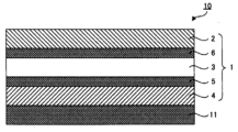
- Another embodiment of the present invention provides an insulating film with a steel plate comprising the insulating film for a solar cell module and a steel plate disposed on the surface of the insulating film for a solar cell module on the side of the polyethylene-based resin layer.
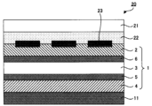
- Another embodiment of the present embodiment provides a solar cell module having a transparent substrate, a sealing material sheet, a solar cell, the insulating film for a solar cell module, and a steel plate in this order.
- An embodiment of the second aspect of the present disclosure is an insulating film for a solar cell module, which is arranged between a solar cell and a wiring sheet in a solar cell module, and conforms to JIS-K-7133-1999. , an insulating substrate having a rate of dimensional change in the MD direction of 2.0% or less and a thermal shrinkage rate in the TD direction of 1.5% or less when held at 150 ° C. for 30 minutes; and a wiring sheet-side sealing material layer having a polyethylene film disposed on one surface of a base material, wherein the wetting tension of the surface of the polyethylene film opposite to the insulating base material is 36 dyne/cm.
- an insulating film for a solar cell module which is the above.
- Another embodiment of the present embodiment is an insulating film for a solar cell module arranged between a solar cell and a wiring sheet in a solar cell module, comprising polyethylene terephthalate, polyethylene naphthalate, polybutylene terephthalate, polyimide and polyamide. , a polycarbonate, and a modified polyphenylene ether; and a wiring sheet-side sealing layer disposed on one surface of the insulating substrate and having a polyethylene film. and a material layer, wherein the surface of the polyethylene film opposite to the insulating substrate has a wetting tension of 36 dyne/cm or more.
- Another embodiment of the present embodiment is an insulating film for a solar cell module, which is arranged between a solar cell and a wiring sheet in a solar cell module, and is heated in the MD direction when held at 150° C. for 30 minutes.
- An insulating substrate having a shrinkage rate of 2.0% or less and a thermal shrinkage rate in the TD direction of 1.5% or less, and an insulating substrate disposed on one surface of the insulating substrate and containing a silane-modified resin.
- a wiring sheet side sealing material layer having a polyethylene film, wherein the content of silicon atoms in the polyethylene film is 0.0001% by mass or more and 15.0% by mass or less.
- Another embodiment of the present embodiment is an insulating film for a solar cell module arranged between a solar cell and a wiring sheet in a solar cell module, comprising polyethylene terephthalate, polyethylene naphthalate, polybutylene terephthalate, polyimide and polyamide. , polycarbonate, and modified polyphenylene ether, and a polyethylene film disposed on one side of the insulating substrate and containing a silane-modified resin. and a wiring sheet side encapsulant layer, wherein the content of silicon atoms in the polyethylene film is 0.0001% by mass or more and 15.0% by mass or less.
- Another embodiment of the present embodiment is a wiring sheet with wiring sheet having the above insulating film for a solar cell module, and a wiring sheet disposed on the surface of the insulating film for a solar cell module on the wiring sheet side sealing material layer side. Provide insulation film.
- Another embodiment of the present embodiment provides a solar cell module having, in this order, a transparent substrate, a sealing material sheet, a solar cell, the insulating film for a solar cell module, and a wiring sheet.
- an insulating film for a solar cell module that is excellent in adhesion and insulation to a steel plate.
- an insulating film for a solar cell module that is excellent in dimensional stability and adhesion of the wiring sheet to the wiring.
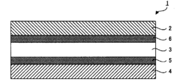
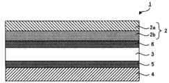
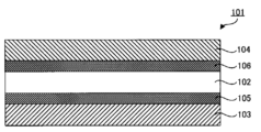
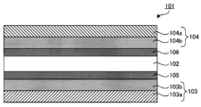
- FIG. 1 is a schematic cross-sectional view illustrating an insulating film for a solar cell module according to the first embodiment of the present disclosure
- FIG. 1 is a schematic cross-sectional view illustrating an insulating film for a solar cell module according to the first embodiment of the present disclosure
- FIG. 1 is a schematic cross-sectional view illustrating an insulating film with a steel plate according to the first embodiment of the present disclosure
- FIG. 1 is a schematic cross-sectional view illustrating a solar cell module according to a first embodiment of the present disclosure
- FIG. 5 is a schematic cross-sectional view illustrating an insulating film for a solar cell module according to the second embodiment of the present disclosure
- FIG. 5 is a schematic cross-sectional view illustrating an insulating film for a solar cell module according to the second embodiment of the present disclosure
- FIG. 5 is a schematic cross-sectional view illustrating an insulating film for a solar cell module according to the second embodiment of the present disclosure
- FIG. 5 is a schematic cross-sectional view illustrating an insulating film with a wiring sheet according to the second embodiment of the present disclosure
- FIG. 4 is a schematic cross-sectional view illustrating a solar cell module according to a second embodiment of the present disclosure
- 2 when expressing a mode of arranging another member on top of a certain member, when simply describing “above” or “below”, unless otherwise specified, 2 includes both cases in which another member is arranged directly above or directly below, and cases in which another member is arranged above or below a certain member via another member.
- 2 when expressing a mode in which another member is arranged on the surface of a certain member, unless otherwise specified, when simply described as “on the surface”, it means directly above, so as to contact the certain member, unless otherwise specified.
- it includes both the case of arranging another member directly below and the case of arranging another member above or below a certain member via another member.
- the insulating film for a solar cell module in the present embodiment is a member arranged between a solar cell and a steel plate in a solar cell module, and includes a sealing material layer, an insulating base material, and a polyethylene film. It has a system resin layer in this order.
- the insulating film for a solar cell module in this embodiment has two modes. Hereinafter, each embodiment will be described separately.
- a first embodiment of the insulating film for a solar cell module according to the present embodiment has a sealing material layer, an insulating substrate, and a polyethylene-based resin layer in this order, and the polyethylene-based resin layer is made of polyethylene. It is a film, and the surface of the polyethylene-based resin layer opposite to the insulating substrate has a wetting tension of 36 dyne/cm or more.
- FIG. 1 is a schematic cross-sectional view showing an example of the insulating film for a solar cell module of this embodiment.
- the insulating film 1 for solar cell module has a sealing material layer 2, an insulating substrate 3, and a polyethylene resin layer 4 in this order.
- the polyethylene-based resin layer 4 is a polyethylene film, and the surface of the polyethylene-based resin layer 4 opposite to the insulating substrate 3 has a predetermined wettability.
- the insulating film 1 for solar cell module of this embodiment may have a first adhesive layer 5 between the insulating base material 3 and the polyethylene-based resin layer 4 . Moreover, the insulating film 1 for a solar cell module of this embodiment may have a second adhesive layer 6 between the insulating base material 3 and the encapsulant layer 2 .
- the insulating film for a solar cell module of this embodiment is a member arranged between the solar cell and the steel plate in the solar cell module, the sealing material layer is arranged on the side of the solar cell, and the polyethylene resin layer is It is placed on the steel plate side.
- the surface of the polyethylene-based resin layer on the side opposite to the insulating substrate has a predetermined wetting tension, so that the adhesion to the steel plate used in the solar cell module is excellent.
- a silane coupling agent is added to the encapsulant sheet used for the solar cell module in order to improve the adhesion to the solar cell, the surface protective sheet and the back protective sheet.
- the silane coupling agent contained in the encapsulant sheet may adhere to the roll. be.
- the silane coupling agent contained in the encapsulant sheets may transfer to other surfaces of the encapsulant sheets. The thinner the encapsulant sheet, the more likely it is to be affected by adhesion or transfer of the silane coupling agent to adhesion. Therefore, when the encapsulant sheet contains a silane coupling agent, it is necessary to increase the thickness of the encapsulant sheet.
- the wetting tension of the surface of the polyethylene-based resin layer opposite to the insulating substrate is within a predetermined range, thereby improving the adhesion to the steel plate. can be done. Therefore, it is not necessary to contain a silane coupling agent for improving adhesion, and the thickness of the polyethylene film constituting the polyethylene-based resin layer can be reduced.
- the polyethylene film is relatively thin in thickness, referred to as the "film". Therefore, the thickness of the entire insulating film for a solar cell module can be reduced. Therefore, when the insulating film for a solar cell module of this embodiment is used in a solar cell module, the thickness and weight of the solar cell module can be reduced.
- a surface protection sheet, a sealing material sheet, a solar cell, a sealing material sheet, an insulating substrate, a sealing material sheet, and a steel plate are prepared, and these members are
- various members are used at the time of lamination. Productivity is low and costs are high.
- the insulating film for a solar cell module of this embodiment is obtained by previously integrating a sealing material layer, an insulating base material, and a polyethylene film. Therefore, when manufacturing a solar cell module using the insulating film for a solar cell module of the present embodiment, for example, a transparent substrate, a sealing material sheet, a solar cell, an insulating film for a solar cell module,
- the steel plates may be sequentially laminated and integrated by thermocompression bonding, which can reduce the number of steps and the number of members and improve productivity.
- a dry lamination method As a method for laminating a plurality of films, for example, a dry lamination method is known.
- the dry lamination method there is a limit to the thickness that can be laminated. Since the encapsulant sheet is generally relatively thick, the total thickness of the encapsulant sheet, the insulating base material, and the encapsulant sheet is, for example, 1 mm or more. Therefore, it is difficult to laminate the encapsulant sheet, the insulating base material, and the encapsulant sheet by the dry lamination method.
- the sealing material layer, the insulating substrate and the polyethylene film can be laminated by a dry lamination method. It is possible. Therefore, an insulating film for a solar cell module can be obtained in which the encapsulant layer, the insulating base material, and the polyethylene film are integrated in advance.
- the insulating film for a solar cell module of this embodiment has an insulating base material between the sealing material layer and the polyethylene film, so that the insulating property can be improved. can suppress the occurrence of short-circuit failure.
- the polyethylene-based resin layer in this embodiment is arranged on the surface of the insulating substrate opposite to the sealing material layer, and is a member arranged on the outermost surface of the insulating film for a solar cell module. Further, the polyethylene resin layer is a polyethylene film, and the wet tension of the surface of the polyethylene resin layer opposite to the insulating substrate is a predetermined value or more.
- the wetting tension of the surface of the polyethylene-based resin layer opposite to the insulating substrate is 36 dyne/cm or more, preferably 40 dyne/cm or more, and more preferably 46 dyne/cm or more. can.
- the wet tension is within the above range, the adhesion to the steel plate can be improved.
- the higher the wetting tension, the better, and the upper limit of the wetting tension is not particularly limited.
- wet tension of the surface of the polyethylene-based resin layer opposite to the insulating substrate can be measured according to JIS K6768: 1999 (wet tension test method for plastic films and sheets). The details of the method for measuring the wetting tension are as described in Examples.
- the surface of the polyethylene-based resin layer opposite to the insulating base material As a method for adjusting the wetting tension of the surface of the polyethylene-based resin layer opposite to the insulating base material within the above range, for example, as described later, the surface of the polyethylene-based resin layer opposite to the insulating base material and a method of applying a surface treatment to the surface.
- the polyethylene-based resin layer is preferably surface-treated.
- the surface of the polyethylene-based resin layer opposite to the insulating base material is surface-treated, as described above, the wet tension of the surface of the polyethylene-based resin layer opposite to the insulating base material can be adjusted within a predetermined range, and the adhesion to the steel plate can be enhanced.
- the surface of the polyethylene-based resin layer facing the insulating substrate is surface-treated, the adhesion to the first adhesive layer can be enhanced.
- the surface treatment is not particularly limited as long as it can adjust the wetting tension of the surface of the polyethylene resin layer opposite to the insulating substrate within a predetermined range.
- treatment plasma treatment, ultraviolet treatment, electron beam treatment, flame treatment, and the like.
- corona treatment is preferable from the viewpoint of processing cost and damage reduction to the polyethylene-based resin layer.
- the polyethylene resin layer is a polyethylene resin film.
- Polyethylene films are relatively thin in thickness, as they are referred to as "films".
- the thickness of the polyethylene film is preferably 10 ⁇ m or more and 300 ⁇ m or less, more preferably 20 ⁇ m or more and 200 ⁇ m or less, and even more preferably 30 ⁇ m or more and 100 ⁇ m or less.
- the polyethylene film constituting the polyethylene-based resin layer does not need to contain a silane coupling agent to improve adhesion, so the thickness of the polyethylene film can be reduced. can.
- the thickness of the polyethylene-based resin layer is the average value of 10 arbitrary thicknesses obtained by measuring the cross-section in the thickness direction of the insulating film for a solar cell module observed with an optical microscope. can be done.
- the thickness of the polyethylene-based resin layer is measured by peeling off the polyethylene-based resin layer from the insulating film for solar cell modules, or the thickness of the polyethylene-based resin layer is measured by peeling off the insulating film for solar cell modules and measuring the thickness of the entire insulating film for solar cell modules.
- the thickness of the polyethylene-based resin layer can also be obtained from the difference between the thickness of the insulating film for a solar cell module and the thickness of the member after peeling off the polyethylene-based resin layer from the insulating film for solar cell module.
- the thickness can be measured by, for example, a micrometer or a mass method. Unless otherwise specified, the same method can be used for measuring the thickness of other members.
- the polyethylene-based resin layer is not particularly limited as long as it satisfies the wet tension described above, but it is preferably a non-crosslinked polyethylene-based resin layer.
- a sealing material sheet used in a solar cell module for example, an ethylene-vinyl acetate copolymer (EVA) is used as a base resin and a sealing material sheet containing a cross-linking agent, or a polyolefin resin is used as a base resin.
- EVA ethylene-vinyl acetate copolymer
- a cross-linked encapsulant sheet such as a encapsulant sheet containing a resin and a cross-linking agent is known.
- These crosslinked encapsulant sheets are uncrosslinked resin films, which are crosslinked by heating during production of the solar cell module or by heating in another crosslinking step.
- the crosslinkable encapsulant sheet contains a silane coupling agent in addition to the crosslinker
- a crosslinking reaction of the base resin and a grafting reaction of the silane coupling agent to the base resin are necessary.
- the range of heating conditions when manufacturing battery modules is narrowed.
- the crosslinkable encapsulant sheet contains a silane coupling agent in addition to the crosslinker
- when the encapsulant sheet, the insulating base material, and the encapsulant sheet are laminated by a dry lamination method, dry After applying the adhesive for lamination, when the solvent contained in the adhesive for dry lamination is dried, the cross-linking agent and silane coupling agent contained in the cross-linkable encapsulant sheet volatilize. Therefore, it is difficult to laminate a crosslinkable encapsulant sheet, an insulating substrate, and a crosslinkable encapsulant sheet by a dry lamination method.
- the non-crosslinked polyethylene-based resin layer does not require a cross-linking step when manufacturing a solar cell module using the insulating film for a solar cell module according to the present embodiment. It is possible to shorten the time. Furthermore, as described above, the non-crosslinked polyethylene-based resin layer does not contain a crosslinking agent, and in the present embodiment, there is no need to contain a silane coupling agent to improve adhesion. It is possible to widen the range of heating conditions when manufacturing the module. Also, a non-crosslinked polyethylene resin layer does not contain a crosslinking agent, and in this embodiment, does not need to contain a silane coupling agent, and is suitable for lamination by a dry lamination method.
- a resin having a relatively high melt mass flow rate (MFR) and a relatively low melting point is used for the crosslinked polyethylene resin layer.
- MFR melt mass flow rate
- a resin composition containing such a base resin if the film-forming speed is increased, the possibility of the occurrence of a phenomenon in which the encapsulant sheet is removed by the rubber roll increases due to insufficient cooling.
- a resin with a relatively high melting point is used for the non-crosslinked polyethylene resin layer in consideration of heat resistance.
- the density of the resin tends to be relatively high and the melt mass flow rate (MFR) of the resin tends to be relatively low. Therefore, it is possible to suppress the occurrence of the above problems.
- a non-crosslinked polyethylene resin layer usually does not contain a cross-linking agent.
- the polyethylene resin layer does not contain a cross-linking agent, it can be called a non-crosslinked polyethylene resin layer. That is, it is preferable that the polyethylene-based resin layer does not contain a cross-linking agent.
- the presence or absence of a cross-linking agent in the polyethylene-based resin layer can be analyzed, for example, by infrared spectroscopy (IR) or gas chromatography-mass spectrometry (GC-MS).
- IR infrared spectroscopy
- GC-MS gas chromatography-mass spectrometry
- the gel fraction of the non-crosslinked polyethylene resin layer is usually 0%.
- the gel fraction of the non-crosslinked polyethylene resin layer is 0%, it can be called a non-crosslinked polyethylene resin layer. That is, the gel fraction of the polyethylene-based resin layer is preferably 0%.
- the “gel fraction (%)” in this specification means that 1.0 g of a sample is placed in a resin mesh, extracted with xylene at 110 ° C. for 24 hours, then taken out together with the resin mesh, dried, weighed, and extracted. The gel fraction was obtained by measuring the mass % of the residual insoluble matter by comparing the mass before and after the sample.
- the gel fraction of 0% means that the residual insoluble matter is substantially zero. More specifically, "0% gel fraction" means that the residual insoluble matter does not exist at all, and that the mass% of the residual insoluble matter measured by a precision balance is less than 0.05% by mass. shall mean.
- the residual insoluble matter does not include pigment components other than resin components. If inclusions other than these resin components are mixed in the residual insoluble matter as a result of the above test, for example, by separately measuring the content of these inclusions in the resin component in advance, these It is possible to calculate the gel fraction that should be originally obtained for the residual insoluble matter derived from the resin component excluding inclusions.
- the polyethylene resin layer contains a silane-modified resin
- the gel fraction of the polyethylene resin layer is 15% or less, it is a non-crosslinked polyethylene resin layer.
- the silane-modified resin itself contains a gel. This is because it is different from
- the gel fraction of the polyethylene-based resin layer is preferably 2% or more and 10% or less.
- the polyethylene-based resin layer contains polyethylene-based resin.
- the polyethylene-based resin is an ethylene homopolymer or a copolymer containing ethylene as a main component.
- an ⁇ -olefin is used as another component.
- One or more selected from methyl-1-butene, 3-methyl-1-butene, 1-hexene, 1-heptene, 1-octene, 1-nonene and 1-decene can be used.
- the polyethylene-based resin is not particularly limited as long as it is possible to obtain a polyethylene-based resin layer that satisfies the wet tension described above. preferable.
- polyethylene resins include high-density polyethylene (HDPE), low-density polyethylene (LDPE), linear low-density polyethylene (LLDPE), metallocene-based linear low-density polyethylene (M-LLDPE), and ultra-low density polyethylene. (VLDPE) and the like.
- Polyethylene-based resins may be used singly or in combination of two or more.
- low-density polyethylene LDPE
- linear low-density polyethylene LLDPE
- metallocene-based linear low-density polyethylene M-LLDPE
- very low-density polyethylene VLDPE
- linear low-density polyethylene LLDPE
- metallocene-based linear low-density polyethylene M-LLDPE
- VLDPE very low-density polyethylene
- LLDPE linear low-density polyethylene
- M-LLDPE metallocene-based linear low-density polyethylene
- metallocene-based linear low-density polyethylene M-LLDPE
- Metallocene-based linear low-density polyethylene M-LLDPE
- Metallocene-based linear low-density polyethylene M-LLDPE
- Metallocene-based linear low-density polyethylene M-LLDPE is synthesized using a single-site metallocene catalyst.
- Such polyethylene has less side chain branching and a uniform copolymer distribution. For this reason, the molecular weight distribution is narrow, and the density can be lowered as described later, and flexibility can be imparted to the polyethylene-based resin layer. As a result of imparting flexibility to the polyethylene-based resin layer, the adhesion between the polyethylene-based resin layer and the steel plate can be enhanced.
- Metallocene-based linear low-density polyethylene (M-LLDPE) is also excellent in heat resistance.
- the density of the polyethylene-based resin is not particularly limited.
- the lower limit is preferably 0.870 g/cm 3 or more, and more preferably 0.875 g/cm 3 or more. In particular, it is preferably 0.880 g/cm 3 or more.
- the upper limit is preferably 0.970 g/cm 3 or less, more preferably 0.950 g/cm 3 or less, and particularly preferably 0.930 g/cm 3 or less.
- the density of the polyethylene-based resin can be measured, for example, by the pycnometer method conforming to JIS K7112:1999.
- the melting point of the polyethylene resin is not particularly limited.
- the lower limit is preferably 55°C or higher, more preferably 80°C or higher, and particularly preferably 90°C or higher. preferable.
- the upper limit is preferably 130° C. or lower, more preferably 120° C. or lower, and even more preferably 115° C. or lower.
- the melting point of the resin can be determined by differential scanning calorimetry (DSC) in accordance with JIS K7121:2012 (plastic transition temperature measurement method). In this case, when there are two or more melting point peaks, the higher temperature can be taken as the melting point.
- DSC differential scanning calorimetry
- the melt mass flow rate (MFR) of the polyethylene resin at 190° C. is preferably 0.5 g/10 minutes or more, more preferably 1 g/10 minutes or more, as a lower limit. More preferably, it is 5 g/10 minutes or more.
- the upper limit is preferably 20 g/10 minutes or less, more preferably 10 g/10 minutes or less, and even more preferably 8 g/10 minutes or less.
- melt mass flow rate (MFR) of polyethylene resin can be measured by A method in accordance with JIS K7210-1-1999.
- the measurement conditions are a temperature of 190° C. and a load of 2.16 kg.
- the melt mass flow rate (MFR) of the polyethylene-based resin layer at 190° C. is preferably 0.5 g/10 minutes or more, more preferably 1 g/10 minutes or more, as a lower limit. 0.5 g/10 minutes or more is more preferable.
- the upper limit is preferably 20 g/10 minutes or less, more preferably 10 g/10 minutes or less, and even more preferably 8 g/10 minutes or less.
- the MFR of the polyethylene-based resin layer refers to the MFR of the polyethylene-based resin composition forming the polyethylene-based resin layer.
- the method for measuring the MFR of the polyethylene-based resin layer is the same as the method for measuring the MFR of the polyethylene-based resin described above.
- the polyethylene-based resin layer may contain only polyethylene-based resin as a resin component, or may further contain resin other than polyethylene-based resin in addition to polyethylene-based resin. In the latter case, the polyethylene-based resin layer preferably contains a polyethylene-based resin as a main component. That the polyethylene-based resin layer contains the polyethylene-based resin as a main component means that the ratio of the polyethylene-based resin is the largest among all the resin components.
- the ratio of the polyethylene-based resin to the total resin components in the polyethylene-based resin layer is, for example, 50% by mass or more, may be 60% by mass or more, or may be 70% by mass or more. Moreover, the ratio of the polyethylene-based resin is, for example, 99% by mass or less, may be 95% by mass or less, or may be 90% by mass or less. In addition, 100 mass % may be sufficient as the ratio of the said polyethylene-type resin.
- the polyethylene-based resin layer can contain additives such as ultraviolet absorbers, light stabilizers, antioxidants, antiblocking agents, etc., as necessary.
- the ratio of each resin component contained in each layer of the insulating film for solar cell module in this embodiment can be analyzed from the peak ratio detected by nuclear magnetic resonance (NMR).
- the method of forming the polyethylene resin layer is not particularly limited, and examples thereof include the inflation method and the T-die method.
- the insulating substrate in this embodiment is a member that is disposed between the sealing material layer and the polyethylene-based resin layer and has insulating properties.
- the insulating base material for example, a resin base material having insulating properties can be used.
- resins forming the insulating base include polyethylene terephthalate, polyethylene naphthalate, polybutylene terephthalate, polyimide, polyamide, polycarbonate, and modified polyphenylene ether. These resins may be used individually by 1 type, and may use 2 or more types together.
- the insulating substrate preferably contains polyethylene terephthalate. This is because an insulating base material having excellent insulating properties, dimensional stability, heat resistance and the like can be obtained.
- the insulating base material may contain a coloring agent.
- coloring agents include white pigments and dark pigments. Among them, white pigments are preferred.
- the insulating base material contains a white pigment
- the insulating base material can reflect visible light and near-infrared rays that contribute to the power generation of the solar cell.
- visible light and near-infrared rays can be reflected by the insulating base material and made to enter the solar cell again. It is possible to improve the power generation efficiency of the module.
- the insulating base material contains a white pigment
- the insulating base material can reflect infrared rays that do not contribute to the power generation of the solar cell.
- infrared rays are reflected without being absorbed by the insulating base material, so that the temperature rise of the solar cell module can be suppressed. .
- titanium oxide for example, titanium oxide, calcium carbonate, barium sulfate, silicon oxide, etc.
- titanium oxide is preferred.
- the average particle diameter of titanium oxide is preferably, for example, 0.2 ⁇ m or more and 1.5 ⁇ m or less.
- Such an insulating base material containing a white pigment reflects well visible light and near-infrared rays that contribute to the power generation of a solar cell. , the power generation efficiency of the solar cell module can be improved.
- the average particle size of the white pigment can be obtained by observation with a transmission electron microscope (TEM), for example. Specifically, after taking a picture of the primary particle size of the white pigment using a transmission electron microscope (JEM-1230) manufactured by JEOL Ltd., the image is transferred to the image analysis type particle size distribution measurement software manufactured by Mountec ( A value obtained by performing statistical processing with MAC-View Ver.3) can be adopted. A volume-based equivalent circle diameter is used for calculating the average particle diameter.
- the average particle size of various resins and inorganic filler powder materials in the present specification can be measured by the above method.
- the lower limit of the white pigment content in the insulating substrate is preferably 2% by mass or more, more preferably 4% by mass or more, and even more preferably 5% by mass or more.
- the upper limit is preferably 20% by mass or less, more preferably 15% by mass or less, and even more preferably 10% by mass or less. If the content of the white pigment is too small, the function of reflecting visible light, near-infrared rays and infrared rays may become insufficient. Also, if the content of the white pigment is too large, there is a possibility that the effect of improving the reflectance of visible light, near-infrared rays and infrared rays cannot be obtained by further addition. On the other hand, if the content of the white pigment is too large, there is a possibility that the film formability will be deteriorated or the smoothness of the insulating substrate will be deteriorated due to bleeding out or the like.
- the appearance is not good. may be damaged.
- the insulating base material contains a dark pigment
- the region where the solar cells are arranged and the solar cell It is possible to match the color tone with the area where is not arranged. As a result, the appearance and design of the solar cell module can be improved.
- dark color in this specification means standard light source D65 measured with reflected light in accordance with JIS Z8722-2009 with a standard white plate laid on the base, CIE color coordinates at a viewing angle of 2°. a * and b * values in the range of ⁇ 4.0 ⁇ a * ⁇ 5.0 and ⁇ 10.0 ⁇ b * ⁇ 1.0.
- the dark pigment is not particularly limited as long as it exhibits a dark appearance, and examples thereof include carbon black; perylene pigments; and mixed dark pigments that are mixtures of brown pigments and blue pigments. .
- brown pigments contained in the mixed pigment include benzimidazolone pigments, 4-[(2,5-dichlorophenyl)azo]-3-hydroxy-N-(2,5-dimethoxyphenyl)-2 -naphthalenecarboxamide, 1-[(4-nitrophenyl)azo]-2-naphthalenol, bis[3-hydroxy-4-(phenylazo)-2-naphthalenecarboxylic acid] copper salt, N,N'-bis(2, 4-dinitrophenyl)-3,3′-dimethoxy-1,1′-biphenyl-4,4′-diamine, 3,4,9,10-perylenetetracarboxylic diimide, ⁇ 2,2′(1H,1′ H)-binaphtho[2,1-b]thiophene-1,1′-dione, N,N′-(10,15,16,17-tetrahydro-5,10,15,17-tetraoxo-5H
- a benzimidazolone pigment is a pigment having a benzimidazolone skeleton represented by the following general formula. Specifically, C.I. I. Pigment Yellow 120, C.I. I. Pigment Yellow 151, C.I. I. Pigment Yellow 154, C.I. I. Pigment Yellow 175, C.I. I. Pigment Yellow 180, C.I. I. Pigment Yellow 181, C.I. I. Pigment Yellow 194, C.I. I. Pigment Red 175, C.I. I. Pigment Red 176, C.I. I. Pigment Red 185, C.I. I. Pigment Red 208, C.I. I.
- Pigment Violet 32 C.I. I. Pigment Orange 36, C.I. I. Pigment Orange 62, C.I. I. Pigment Orange 72, C.I. I. Pigment Brown 25, etc., but not limited to these. Among them, from the viewpoint of color gamut, C.I. I. Pigment Brown 25 is preferred.
- Examples of blue pigments contained in the mixed dark pigment include phthalocyanine pigments.
- a phthalocyanine-based pigment is a pigment having a phthalocyanine skeleton, and is a concept including phthalocyanines to which various metals are coordinated. Specifically, C.I. I. Pigment Green 7, C.I. I. Pigment Green 36, C.I. I. Pigment Green 37, C.I. I. Pigment Blue 16, C.I. I. Pigment Blue 75, C.I. I. Pigment Blue 15 and the like.
- the mixing ratio of the brown pigment and the blue pigment in the mixed dark pigment is appropriately adjusted according to the color tone of the solar cell.
- the mixing ratio of the brown pigment and the blue pigment can be, for example, within the range of 45:55 to 70:30.
- the content of the dark pigment in the insulating substrate is preferably 10% by mass or more, more preferably 15% by mass or more, and further preferably 20% by mass or more. preferable.
- the upper limit is preferably 50% by mass or less, more preferably 35% by mass or less, and even more preferably 20% by mass or more and 30% by mass or less. If the content of the dark pigment is within the above range, an insulating base material with high insulating properties and design properties can be obtained.
- the insulating base material can contain additives in addition to the above, if necessary.
- additives include ultraviolet absorbers, light stabilizers, antioxidants, antistatic agents, flame retardants, and the like.
- the thickness of the insulating substrate is appropriately set according to the system voltage required for the solar cell module, etc.
- the lower limit is preferably 25 ⁇ m or more, more preferably 40 ⁇ m or more. It is preferably 45 ⁇ m or more, and more preferably 45 ⁇ m or more.
- the upper limit is preferably 350 ⁇ m or less, more preferably 200 ⁇ m or less, and even more preferably 160 ⁇ m or less. If the thickness of the insulating base material is too thin, there is a possibility that desired properties such as insulating properties and design properties cannot be obtained, and that handling suitability of the insulating film for solar cell module is deteriorated. Moreover, if the thickness of the insulating base material is too thick, it may become difficult to reduce the thickness and weight of the solar cell module.
- the encapsulant layer in this embodiment is arranged on the surface of the insulating substrate opposite to the polyethylene-based resin layer, and is a member arranged on the outermost surface of the insulating film for a solar cell module.
- the sealing material layer is not particularly limited as long as it can be used as a sealing material for a solar cell module. Layers can be mentioned.
- polyolefins include polyethylene resins, ethylene-vinyl acetate copolymers (EVA), and polyolefin elastomers (POE).
- the sealing material layer may contain a coloring agent.
- Colorants include dark pigments.
- the dark pigment may be the same as the dark pigment used for the insulating substrate.
- the sealing material layer is preferably a non-crosslinked polyolefin film.
- a non-crosslinked polyolefin film does not require a cross-linking step when manufacturing a solar cell module using the insulating film for a solar cell module according to the present embodiment, so it is possible to reduce the manufacturing cost and shorten the manufacturing time. be.
- Non-crosslinked polyolefin membranes usually do not contain a cross-linking agent.
- the polyolefin membrane does not contain a cross-linking agent, it can be called a non-crosslinked polyolefin membrane. That is, it is preferable that the polyolefin film does not contain a cross-linking agent.
- the analysis method for the presence or absence of the cross-linking agent in the polyolefin film is as described above.
- the gel fraction of a non-crosslinked polyolefin film is usually 0%.
- the gel fraction of the polyolefin film is 0%, it can be said that it is a non-crosslinked polyolefin film. That is, the gel fraction of the polyolefin film is preferably 0%.
- the polyolefin film contains a silane-modified resin, even if the gel fraction of the polyolefin film is, for example, 15% or less, as in the case of the polyethylene-based resin layer, non-crosslinked polyolefin membrane.
- the definition of the gel fraction and the method for measuring the gel fraction are as described above.
- the polyolefin film in this embodiment is a member that constitutes the sealing material layer, and is a member that is arranged on the outermost surface of the sealing material layer on the side opposite to the insulating base material. .
- the polyolefin film contains a polyolefin resin.
- the polyolefin-based resin is not particularly limited as long as it can be used as a sealing material for solar cell modules. Among them, a non-crosslinked polyolefin-based resin is preferable for the reasons described above.
- Non-crosslinked polyolefin resins include, for example, polyethylene resins, polypropylene resins, propylene-ethylene copolymer resins, ethylene- ⁇ olefin copolymer resins, and the like.
- polyethylene-based resins are preferred. That is, the polyolefin film is preferably a polyethylene film. This is because the polyethylene-based resin has excellent sealing properties.
- the polyethylene-based resin is not particularly limited as long as it can be used as a sealing material for solar cell modules. Among them, non-crosslinked polyethylene-based resin is preferable for the reasons described above.
- polyethylene resins include high-density polyethylene (HDPE), low-density polyethylene (LDPE), linear low-density polyethylene (LLDPE), metallocene-based linear low-density polyethylene (M-LLDPE), and ultra-low density polyethylene. (VLDPE).
- Polyethylene-based resins may be used singly or in combination of two or more.
- low-density polyethylene LDPE
- linear low-density polyethylene LLDPE
- metallocene-based linear low-density polyethylene M-LLDPE
- very low-density polyethylene VLDPE
- linear low-density polyethylene LLDPE
- metallocene-based linear low-density polyethylene M-LLDPE
- VLDPE very low-density polyethylene
- LLDPE linear low-density polyethylene
- M-LLDPE metallocene-based linear low-density polyethylene
- metallocene-based linear low-density polyethylene M-LLDPE
- metallocene-based linear low-density polyethylene M-LLDPE
- metallocene-based linear low-density polyethylene M-LLDPE
- metallocene-based linear low-density polyethylene M-LLDPE
- M-LLDPE metallocene-based linear low-density polyethylene
- the density of the polyethylene resin is not particularly limited.
- the lower limit is preferably 0.870 g/cm 3 or more, more preferably 0.875 g/cm 3 or more, More preferably, it is 0.880 g/cm 3 or more.
- the upper limit is preferably 0.970 g/cm 3 or less, more preferably 0.950 g/cm 3 or less, and even more preferably 0.930 g/cm 3 or less.
- the method for measuring the density of polyethylene resin is as described above.
- the melting point of the polyethylene-based resin is not particularly limited.
- the lower limit is preferably 55° C. or higher, more preferably 80° C. or higher, and even more preferably 90° C. or higher.
- the upper limit is preferably 130° C. or lower, more preferably 120° C. or lower, and even more preferably 115° C. or lower. If the melting point of the polyethylene-based resin is too high, it is necessary to raise the heating temperature when manufacturing the solar cell module by integrating the solar cell module insulating film of the present embodiment by thermocompression bonding, which increases the manufacturing cost. increase, or the insulating base material may deteriorate.
- the melting point of the polyethylene-based resin is too high, the embedding of wiring and the like in the encapsulant layer becomes insufficient, and there is a possibility that the insulation cannot be ensured.
- the melting point of the polyethylene-based resin is too low, the polyethylene film may melt in the usage environment of the solar cell module.
- the polyolefin film may contain only the polyolefin resin as the resin component, or may further contain a resin other than the polyolefin resin in addition to the polyolefin resin. In the latter case, the polyolefin film preferably contains a polyolefin resin as a main component. In addition, the fact that the polyolefin film contains the polyolefin resin as the main component means that the ratio of the polyolefin resin is the largest among all the resin components.
- the ratio of the polyolefin-based resin to the total resin components in the polyolefin film is, for example, 50% by mass or more, may be 60% by mass or more, or may be 70% by mass or more. Further, the proportion of the polyolefin resin is, for example, 99% by mass or less, may be 95% by mass or less, or may be 90% by mass or less. In addition, the ratio of the polyolefin resin may be 100% by mass.
- the polyolefin film preferably contains a silane modified resin.
- silane-modified resin By including the silane-modified resin in the polyolefin film, it is possible to improve adhesion to the solar cell, strength, durability, and the like.
- the polyolefin film contains a silane-modified resin
- it is not necessary to contain a silane coupling agent to improve adhesion so the thickness of the polyolefin film can be reduced.
- the thickness of the entire insulating film for a solar cell module can be reduced. Therefore, when the insulating film for a solar cell module of this embodiment is used in a solar cell module, the thickness and weight of the solar cell module can be reduced.
- the polyolefin film when the polyolefin film is a non-crosslinked polyolefin film and contains a silane-modified resin, it does not contain a cross-linking agent and contains a silane coupling agent to improve adhesion. Since it is not necessary, it is possible to widen the range of heating conditions when manufacturing a solar cell module.
- the polyolefin film when the polyolefin film is a non-crosslinked polyolefin film and contains a silane-modified resin, it does not contain a cross-linking agent and does not need to contain a silane coupling agent to improve adhesion. It is suitable for lamination by a lamination method.
- silane-modified resins include silane-modified polyolefin resins.
- a silane-modified polyolefin resin is a copolymer of an ⁇ -olefin and an ethylenically unsaturated silane compound.
- the above copolymer include random copolymers, alternating copolymers, block copolymers, and graft copolymers.
- the above copolymer is preferably a graft copolymer, preferably a graft copolymer having a polyolefin as a main chain and an ethylenically unsaturated silane compound as a side chain.
- Such a graft copolymer has a high degree of freedom of silanol groups that contribute to adhesion, and thus can further improve adhesion to the solar cell.
- ⁇ -olefins constituting the silane-modified polyolefin resin include, for example, ethylene, propylene, 1-butene, isobutylene, 1-pentene, 2-methyl-1-butene, 3-methyl-1-butene, 1-hexene, 1 -heptene, 1-octene, 1-nonene, 1-decene and the like.
- the ⁇ -olefins may be used singly or in combination of two or more.
- polyethylene is preferred. That is, the silane-modified polyolefin resin is preferably a silane-modified polyethylene resin. This is because the silane-modified polyethylene resin has good compatibility with the polyethylene-based resin contained in the polyolefin film.
- the silane-modified polyethylene resin is preferably a resin obtained by graft-polymerizing a linear low-density polyethylene (LLDPE) as a main chain with an ethylenically unsaturated silane compound as a side chain.
- LLDPE linear low-density polyethylene
- Examples of the ethylenically unsaturated silane compounds include vinyltrimethoxysilane, vinyltriethoxysilane, vinyltripropoxysilane, vinyltriisopropoxysilane, vinyltributoxysilane, vinyltripentyloxysilane, vinyltriphenoxysilane, vinyl Mention may be made of tribenzyloxysilane, vinyltrimethylenedioxysilane, vinyltriethylenedioxysilane, vinylpropionyloxysilane, vinyltriacetoxysilane, vinyltricarboxysilane.
- the ethylenically unsaturated silane compounds may be used singly or in combination of two or more.
- the silane-modified polyolefin resin can be obtained, for example, by the production method described in JP-A-2003-46105.
- the silane-modified resin may be used singly or in combination of two or more.
- the content of the silane-modified resin in the polyolefin film is not particularly limited. % by mass or more is more preferable.
- the upper limit is preferably 60% by mass or less, more preferably 50% by mass or less, and even more preferably 45% by mass or less. If the content of the silane-modified resin is too small, the effect of improving adhesion by the silane-modified resin may not be sufficiently obtained. On the other hand, if the content of the silane-modified resin is too large, the tensile elongation and heat-welding properties tend to be poor. lower limit
- the content of silicon atoms in the polyolefin film is preferably 0.0001% by mass or more, more preferably 0.001% by mass or more, and 0.01% by mass or more. is more preferable.
- the upper limit is preferably 15.0% by mass or less, more preferably 1.0% by mass or less, and even more preferably 0.5% by mass or less. If the content of silicon atoms in the polyolefin film is within the above range, the polyolefin film will contain a predetermined amount of the silane-modified resin, so that the adhesion to the solar cell can be further improved.
- the content of silicon atoms in the polyolefin film can be quantified by Inductively Coupled Plasma Atomic Emission Spectroscopy (ICP-AES).
- ICP-AES Inductively Coupled Plasma Atomic Emission Spectroscopy
- the polyolefin film may contain a light stabilizer.
- a light stabilizer By including a light stabilizer in the polyolefin film, deterioration of the polyolefin film by ultraviolet rays can be suppressed.
- a hindered amine light stabilizer HALS is preferably used.
- the hindered amine light stabilizer is not particularly limited as long as it can exhibit a light stabilizing action, but for example, a high molecular weight type light stabilizer can be preferably used.
- a copolymer of ethylene and a cyclic aminovinyl compound (hindered amine-based acrylate) having a molecular weight of 30,000 or more can be suitably used as the high-molecular-weight light stabilizer.
- a specific example of a high-molecular-weight light stabilizer is a copolymer of ethylene and a cyclic aminovinyl compound (hindered amine-based acrylate) represented by the following chemical formula (1).
- a specific example of the high-molecular-weight hindered amine light stabilizer is "XJ-100H (trade name)" (molecular weight: 35,000) manufactured by Japan Polyethylene Co., Ltd.
- hindered amine light stabilizer is a NOR-type hindered amine light stabilizer.
- NOR-type hindered amine light stabilizer is a compound containing a group represented by general formula (1).
- R is a substituted or unsubstituted hydrocarbon group or acyl group.
- R include alkyl groups, alkenyl groups, alkylene groups, cycloalkyl groups, bicycloalkyl groups, phenyl groups, naphthyl groups, phenylalkyl groups, alkyl-substituted phenyl groups, hydroxyl-substituted alkyl groups, acyl groups, and alkoxy-substituted alkyl groups. groups, thioalkoxy group-substituted alkyl groups, and the like. Note that * and ** in the general formula (1) indicate states that can be combined with other elements.
- NOR-type hindered amine light stabilizers include compounds represented by general formula (2) or general formula (3).
- R 1 and R 2 are each independently a substituted or unsubstituted hydrocarbon group or acyl group, similar to R in general formula (1) described above. Among them, R 1 and R 2 are each independently preferably an alkyl group having 4 to 20 carbon atoms.
- R 3 and R 4 are each independently a substituted or unsubstituted hydrocarbon group or acyl group, similar to R in general formula (1) described above. Among them, R 3 and R 4 are each independently preferably an alkyl group having 4 or more and 20 or less carbon atoms. R 5 is an alkylene group having 1 to 8 carbon atoms.
- NOR-type hindered amine light stabilizers include "ADEKA STAB LA-81 (trade name)” manufactured by Adeka Corporation, and "TINUVIN PA123 (trade name)” manufactured by BASF Corporation (bis(2,2,2,2,2)decanedioate). 6,6-tetramethyl-1-(octyloxy)-4-piperidinyl) ester), BASF's "TINUVIN XT850FF (trade name)", and the like.
- the hindered amine light stabilizer it is preferable to include a high molecular weight type hindered amine light stabilizer with a molecular weight of 1000 or more and a low molecular weight type hindered amine light stabilizer with a molecular weight of less than 1000.
- the high molecular weight type hindered amine light stabilizer is preferably an NCH 3 type hindered amine light stabilizer.
- the low-molecular weight type hindered amine light stabilizer is preferably a NOR type hindered amine light stabilizer. NOR-type hindered amine light stabilizers capture radicals faster than NH-type or NCH3 -type hindered amine light stabilizers.
- NOR-type low-molecular-weight hindered amine photostabilizers migrated to the surface faster than high-molecular-weight hindered amine photostabilizers, resulting in faster radical radicals than NH-type and NCH3- type hindered amine photostabilizers. and suppressing deterioration of the encapsulant layer.
- NOR-type low-molecular-weight hindered amine photostabilizers exhibiting short-term light resistance exhibit reduced radical scavenging function when exposed to light for a long period of time. When used in combination with a type 3 high molecular weight type hindered amine light stabilizer, it is possible to suppress deterioration of the encapsulant layer for a long period of time.
- high molecular weight hindered amine light stabilizers include N,N',4,7-tetrakis ⁇ 4,6-bis[N-butyl-N-(1,2,2,6,6-pentamethyl -4-piperidyl)amino]-1,3,5-triazin-2-yl ⁇ -4,7-diazadecane-1,10-diamine ("Chimassorb 119 (trade name)” manufactured by BASF), 1,2, 3,4-Butanetetracarboxylic acid, tetramethyl ester, reaction products with 1,2,2,6,6-pentamethyl-4-piperidinoland ⁇ , ⁇ , ⁇ ', ⁇ '-tetramethyl-2,4,8,10-tetraoxaspiro [5.5] undecane-3,9-diethanol ("LA-63P (trade name)” manufactured by Adeka), N,N'-bis(2,2,6,6-tetramethyl-4-piperidyl- Examples include a polymer of 1,6-hexan
- low-molecular-weight hindered amine light stabilizers include Bis (1-octyloxy-2,2,6,6-tetramethyl-4-piperidyl) sebacate ("Tinuvin PA 123 (trade name)” manufactured by BASF). ), Bis (1-undecanoxy-2,2,6,6-tetramethylpiperidin-4-yl) carbonate ("LA-81 (trade name)” manufactured by Adeka), 1-(2-Hydroxy-1,1- dimethyl-ethoxy)-2,2,6,6-tetramethyl-4-piperidinyl octadecanoate and the like.
- hindered amine light stabilizer containing a high molecular weight type hindered amine light stabilizer and a low molecular weight type hindered amine light stabilizer include "TINUVIN XT850FF (trade name)" manufactured by BASF. can.
- the content of the light stabilizer in the polyolefin film is preferably 0.2% by mass or more, and more preferably 0.5% by mass or more.
- the upper limit is preferably 5% by mass or less, more preferably 3% by mass or less.
- the polyolefin film may contain additives other than those described above, if necessary.
- the thickness of the polyolefin film is preferably 10 ⁇ m or more, more preferably 20 ⁇ m or more, and more preferably 30 ⁇ m or more, as a lower limit, for example, from the viewpoint of sealing properties. is more preferred.
- the upper limit is preferably 300 ⁇ m or less, more preferably 200 ⁇ m or less, and even more preferably 100 ⁇ m or less.
- the polyolefin film contains a silane-modified resin, it is not necessary to contain a silane coupling agent to improve adhesion, so the thickness of the polyolefin film can be reduced. can be done.
- the polyolefin film is too thick, it may become difficult to reduce the thickness and weight of the solar cell module.
- the sealing material layer preferably has a polypropylene film on the insulating substrate side of the polyolefin film.
- the sealing material layer 2 has a polypropylene film 2b closer to the insulating substrate 3 than the polyolefin film 2a.
- the sealing material layer can be made rigid enough to be used as a sealing material film. Therefore, even if the thickness of the polyolefin film is thin, the handling property of the sealing material layer can be improved by including the polypropylene film in the sealing material layer. Furthermore, the dimensional stability of the insulating film for solar cell modules can be enhanced.
- the polypropylene film contains polypropylene resin.
- the polypropylene resin may be, for example, a homopolypropylene resin that is a propylene homopolymer, a random polypropylene resin that is a random copolymer of propylene and an ⁇ -olefin, or a block copolymer. It may be a block polypropylene resin.
- the polypropylene film may contain one or more of the various polypropylene resins described above. Among them, it is preferable that the polypropylene resin is a homopolypropylene resin. Since the homopolypropylene resin has high rigidity, it is possible to improve the handleability of the sealing material layer even when the thickness of the polyolefin film is thin. Furthermore, the dimensional stability of the insulating film for solar cell modules can be enhanced.
- the melting point of the polypropylene resin is not particularly limited.
- the lower limit is preferably 90°C or higher, more preferably 110°C or higher, and even more preferably 120°C or higher.
- the upper limit is preferably 180°C or less. It is preferable that the polypropylene resin has a relatively high melting point. On the other hand, if the melting point of the polypropylene resin is too high, the film formability may deteriorate and extrusion molding may become difficult.
- the polypropylene film may contain only polypropylene resin as a resin component, or may contain other resins such that polypropylene resin is the main component.
- having a polypropylene resin as a main component means that the ratio of the polypropylene resin is the largest among all the resin components.
- the ratio of the polypropylene resin to the total resin components of the polypropylene film is, for example, 50% by mass or more, may be 60% by mass or more, may be 65% by mass or more, or may be 70% by mass or more. good.
- the proportion of the polypropylene resin is 100% by mass or less, may be 90% by mass or less, may be 80% by mass or less, or may be 75% by mass or less.
- the ratio of the homopolypropylene resin to the total resin components of the polypropylene film is, for example, 50% by mass or more, may be 60% by mass or more, or is 65% by mass or more. It may be present, and may be 70% by mass or more.
- the proportion of the polypropylene resin is 100% by mass or less, may be 90% by mass or less, may be 80% by mass or less, or may be 75% by mass or less. If the proportion of homopolypropylene resin is too low, the desired rigidity may not be obtained.
- a homopolypropylene resin is inferior in transparency to, for example, a random polypropylene resin.
- the polypropylene film preferably contains an adhesion improver in order to improve adhesion to the polyethylene film.
- adhesion improvers include polyethylene-based elastomers and polyethylene-based plastomers.
- by including a polyethylene-based elastomer or a polyethylene-based plastomer in the polypropylene film not only the adhesion to the polyethylene film can be improved, but also the durability of the sealing material layer can be improved.
- polyethylene-based elastomers and polyethylene-based plastomers include copolymers of ethylene and ⁇ -olefins other than ethylene (hereinafter sometimes referred to as ethylene- ⁇ -olefin copolymers).
- Polyethylene constituting the ethylene- ⁇ -olefin copolymer is not particularly limited, but low-density polyethylene is preferable.
- Low-density polyethylene preferably has a density of 0.870 g/cm 3 or more and 0.910 g/cm 3 or less.
- the density of polyethylene can be measured, for example, by a method conforming to JIS 6922-2:2010.
- Examples of ⁇ -olefins constituting ethylene- ⁇ -olefin copolymers include ⁇ -olefins having 3 or more and 20 or less carbon atoms. Specifically, propylene, 1-butene, 4-methyl-1-pentene, 3-methyl-1-butene, 1-pentene, 1-hexene, 1-heptene, 1-octene, 1-nonene, 1-decene , 1-undecene, 1-dodecene and the like. One or two or more of these are used.
- ethylene- ⁇ -olefin copolymer for example, commercially available products may be used.
- commercially available products include "Tafmer DF-710 (trade name)”, “Tafmer DF-119 (trade name)”, “Tafmer DF-110 (trade name)”, and “Tafmer A-1085S” manufactured by Mitsui Chemicals, Inc. (trade name)”, “Tafmer A-4070S (trade name)”, “Tafmer A-4085S (trade name)”, and “Tafmer A-4090S (trade name)”.
- Kernel KF260T (trade name)
- Kernel KF270 (trade name)
- Kernel KF370 (trade name)
- Kernel KF360T (trade name)
- Kernel KS240T (trade name)” manufactured by Japan Polyethylene Co., Ltd.
- Kernel KS340T product name
- Kernel KS260 (product name)
- Excellen VL100 (trade name)
- Excellen VL102 (trade name)
- Excellen VL200 (trade name)
- Excellen FX201 (trade name)
- Excellen FX301 (trade name)” manufactured by Sumitomo Chemical Co., Ltd. )
- Excellen FX307 (trade name)
- Excellen FX351 (trade name)
- Excellen FX352 (trade name)
- Excellen FX357 (trade name)”.
- the ratio of the adhesion improver to the total resin component of the polypropylene film is, for example, 5% by mass or more, may be 10% by mass or more, or may be 15% by mass or more.
- the proportion of the adhesion improver is, for example, less than 50% by mass, may be 40% by mass or less, may be 30% by mass or less, or may be 20% by mass or less. If the proportion of the adhesion improver is too small, the desired adhesion may not be obtained. Also, if the proportion of the adhesion improver is too high, the transparency of the polypropylene film may be lowered. Moreover, the heat resistance of the polypropylene film may be lowered.
- the polypropylene film may contain a light stabilizer.
- a light stabilizer By including a light stabilizer in the polypropylene film, deterioration of the polypropylene film by ultraviolet rays can be suppressed.
- a hindered amine light stabilizer HALS is preferably used.
- the same hindered amine light stabilizer as used in the polyolefin film can be used.
- the content of the light stabilizer in the polypropylene film is preferably 3% by mass or more, and more preferably 3.5% by mass or more.
- the upper limit is preferably 10% by mass or less, more preferably 4.5% by mass or less.
- the polypropylene film may further contain a polypropylene elastomer (PP elastomer).
- PP elastomer polypropylene elastomer
- the transparency of the polypropylene film can be increased.
- polypropylene-based elastomers examples include copolymers of propylene and ⁇ -olefins other than propylene (hereinafter sometimes referred to as propylene- ⁇ -olefin copolymers).
- Examples of ⁇ -olefins constituting the propylene- ⁇ -olefin copolymer include ⁇ -olefins having 2 or 4 to 20 carbon atoms. Specifically, ethylene, 1-butene, 4-methyl-1-pentene, 1-pentene, 1-hexene, 1-heptene, 1-octene, 1-decene, 1-dodecene, 1-tetradecene, 1-hexadecene , 1-octadecene, 1-eicosene and the like. One or two or more of these are used.
- the propylene- ⁇ -olefin copolymer is preferably propylene, ethylene, or a copolymer of propylene and an ⁇ -olefin other than ethylene.
- Toughmer PN-3560 (trade name), Toughmer PN-0040 (trade name), Toughmer PN-2060 (trade name) manufactured by Mitsui Chemicals, Inc.
- the ratio of the polypropylene-based elastomer to the total resin component of the polypropylene film is, for example, 5% by mass or more, may be 10% by mass or more, or may be 15% by mass or more. Also, the proportion of the polypropylene-based elastomer is, for example, less than 50% by mass, may be 40% by mass or less, may be 30% by mass or less, or may be 20% by mass or less. If the proportion of the polypropylene-based elastomer is less than the above range, the effect of improving the transparency of the sealing material layer may not be obtained. Moreover, when the proportion of the polypropylene-based elastomer exceeds the above range, the heat resistance of the polypropylene film may decrease.
- the polypropylene film may contain additives other than those described above, if necessary.
- the polypropylene film may be surface-treated.
- the adhesion to the second adhesive layer can be enhanced.
- the surface treatment is not particularly limited as long as it can improve the adhesion to the second adhesive layer, and can be the same as the surface treatment applicable to the polyethylene-based resin layer. .
- the thickness of the polypropylene film for example, the lower limit is preferably 10 ⁇ m or more, more preferably 20 ⁇ m or more, and even more preferably 30 ⁇ m or more.
- the upper limit is preferably 300 ⁇ m or less, more preferably 200 ⁇ m or less, and even more preferably 100 ⁇ m or less. Good rigidity can be obtained by setting the thickness of the polypropylene film within the above range.
- the polypropylene film is too thick, it may be difficult to reduce the thickness and weight of the solar cell module.
- the lower limit of the thickness of the encapsulant layer in this embodiment can be, for example, 50 ⁇ m or more, preferably 30 ⁇ m or more, and more preferably 50 ⁇ m or more.
- the upper limit can be 400 ⁇ m or less, preferably 300 ⁇ m or less, and more preferably 200 ⁇ m or less.
- the sealing material layer has the above polyolefin film and polypropylene film
- the polyolefin film and the polypropylene film may be laminated via an adhesive layer, and a multilayer film of the polyolefin film and the polypropylene film is formed by a coextrusion method. It can be molded.
- the sealing material layer preferably contains a coextruded film having a polyolefin film and a polypropylene film.
- a coextruded film having a polyolefin film and a polypropylene film it is not necessary to laminate the polyolefin film and the polypropylene film via an adhesive layer, so the thickness of the encapsulant layer can be reduced. Thereby, the thickness of the entire insulating film for a solar cell module can be reduced. Therefore, when the insulating film for a solar cell module of this embodiment is used in a solar cell module, the thickness and weight of the solar cell module can be reduced.
- production efficiency can be improved.
- the insulating film for a solar cell module of this embodiment can have a first adhesive layer between the insulating substrate and the polyethylene-based resin layer.
- the first adhesive layer is a layer that bonds the insulating substrate and the polyethylene resin layer.
- the adhesive used for the first adhesive layer it is possible to use an adhesive that is generally used for bonding between films. can be used.
- an adhesive for example, a two-liquid type adhesive composed of a main agent having a hydroxyl group and a curing agent having an isocyanate group can be used.
- the main agent having hydroxyl groups preferably contains, for example, a mixture of polyurethane diol and aliphatic polycarbonate diol.
- Polyurethane diol and aliphatic polycarbonate diol, which constitute the main component, are both polyols having hydroxyl groups, and react with a curing agent having isocyanate groups to form an adhesive layer.
- Adhesion and weather resistance of the first adhesive layer can be improved by using a mixture of polyurethane diol and aliphatic polycarbonate diol as the main agent.
- the base compound may optionally contain additives such as tackifiers, stabilizers, fillers, plasticizers, softening point improvers, and catalysts. .
- the curing agent having an isocyanate group preferably contains, for example, a polyisocyanate compound.
- a polyisocyanate compound is a compound having two or more isocyanate groups in one molecule, and the isocyanate groups react with hydroxyl groups in the main polyurethane diol to crosslink the polyurethane diol.
- Such a polyisocyanate compound is not particularly limited as long as it can crosslink the main polyurethane diol, and examples thereof include polyurethane diisocyanate, hexamethylene diisocyanate, and isocyanurate-modified isophorone diisocyanate.
- the first adhesive layer can contain additives as necessary.
- the thickness of the first adhesive layer is appropriately selected according to the desired transparency, adhesive strength, etc., and is preferably 3 ⁇ m or more and 10 ⁇ m or less, for example.
- the insulating film for a solar cell module of this embodiment can have a second adhesive layer between the insulating substrate and the encapsulant layer.
- the second adhesive layer is a layer that bonds the insulating substrate and the encapsulant layer.
- the adhesive used for the second adhesive layer it is possible to use an adhesive that is generally used for bonding between films. can be used.
- an adhesive for example, a two-liquid type adhesive composed of a main agent having a hydroxyl group and a curing agent having an isocyanate group can be used. Since the two-liquid adhesive can be the same as the two-liquid adhesive used for the first adhesive layer, the description thereof is omitted here.
- the second adhesive layer may contain a coloring agent. Since the second adhesive layer contains a coloring agent, when the insulating film for a solar cell module according to the present embodiment is used for a solar cell module, the area where the solar cells are arranged and the area where the solar cells are arranged are not aligned. It is possible to match the color tone with areas where there is no color. As a result, the appearance and design of the solar cell module can be improved.
- coloring agents include dark pigments.
- the insulating substrate and the second adhesive layer contain a colorant, it is preferable that the insulating substrate contains a white pigment and the second adhesive layer contains a dark pigment.
- the second adhesive layer When the second adhesive layer contains a dark pigment, it can transmit near infrared rays and infrared rays. Therefore, when the second adhesive layer contains a dark pigment and the insulating substrate contains a white pigment, the second adhesive layer transmits near-infrared rays, and the insulating substrate allows near-infrared rays to pass through. Since the infrared rays can be reflected, attenuation of the near infrared rays can be suppressed without allowing the second adhesive layer and the insulating substrate to absorb the near infrared rays that contribute to the power generation of the solar cell.
- the second adhesive layer contains a dark pigment and the insulating substrate contains a white pigment, the second adhesive layer transmits near infrared rays and infrared rays, and the insulating substrate Therefore, when the insulating film for a solar cell module according to the present embodiment is used in a solar cell module, the temperature rise of the solar cell module due to absorption of near infrared rays and infrared rays can be suppressed. can be done. In addition, near-infrared rays reflected by the insulating substrate are taken into the surface of the solar battery cell, so that power generation efficiency can be improved.
- the dark pigment can be the same as the dark pigment used for the insulating base material, so the description is omitted here.
- the content of the dark pigment in the second adhesive layer is, for example, preferably 10% by mass or more and 40% by mass or less, more preferably 15% by mass or more and 35% by mass or less, and 20% by mass or more. It is more preferably 30% by mass or less. If the content of the dark pigment is within the above range, the second adhesive layer can have high adhesiveness, high designability, and high near-infrared and infrared-ray transmittance.
- the second adhesive layer can contain additives in addition to the above, if necessary.
- the adhesion of the polyethylene resin layer to the steel plate is, for example, 3 N/ It is preferably 15 mm or more, more preferably 5 N/15 mm or more, and even more preferably 10 N/15 mm or more.
- the adhesion between the insulating film for a solar cell module and the steel plate is excellent. reliability and durability can be improved.
- a test piece of the insulating film for solar cell module cut into a size of 75 mm ⁇ 100 mm and an acrylic-coated steel plate of 0.35 mm thickness and 75 mm ⁇ 50 mm size are used.
- a test piece of the insulating film for a solar cell module is brought into close contact with the coated surface of the coated steel plate with the polyethylene-based resin layer side of the insulating film for a solar cell module facing the coated steel plate.
- a release film e.g., ethylene-tetrafluoroethylene copolymer (ETFE) film
- ETFE ethylene-tetrafluoroethylene copolymer
- thermocompression bonding is performed using a vacuum laminator under the following lamination conditions.
- the release film is removed to create a trigger for peeling in the following peel test.
- the test piece of the insulating film for solar cell module in close contact with the coated steel plate is subjected to a 180° peeling test at a peeling speed of 50 mm/min using a peeling tester to measure adhesion.
- the details of the method for measuring the adhesion are as described in Examples.
- the method for producing the insulating film for a solar cell module of the present embodiment is not particularly limited.
- a second embodiment of the insulating film for a solar cell module according to the present embodiment has a sealing material layer, an insulating base material, and a polyethylene resin layer in this order, and the thickness of the polyethylene resin layer is The thickness is 30 ⁇ m or more and 300 ⁇ m or less, and the wetting tension of the surface of the polyethylene-based resin layer opposite to the insulating substrate is 36 dyne/cm or more.
- FIG. 1 is a schematic cross-sectional view showing an example of the insulating film for a solar cell module of this embodiment.
- the insulating film 1 for solar cell module has a sealing material layer 2, an insulating substrate 3, and a polyethylene resin layer 4 in this order.
- the polyethylene resin layer 4 has a predetermined thickness, and the surface of the polyethylene resin layer 4 opposite to the insulating substrate 3 has a predetermined wetting tension.
- the insulating film 1 for solar cell module of this embodiment may have a first adhesive layer 5 between the insulating base material 3 and the polyethylene-based resin layer 4 . Moreover, the insulating film 1 for a solar cell module of this embodiment may have a second adhesive layer 6 between the insulating base material 3 and the encapsulant layer 2 .
- the insulating film for a solar cell module of this embodiment is a member arranged between the solar cell and the steel plate in the solar cell module, the sealing material layer is arranged on the side of the solar cell, and the polyethylene resin layer is It is placed on the steel plate side.
- the surface of the polyethylene-based resin layer opposite to the insulating substrate has a predetermined wetting tension, so that the adhesion to the steel plate used in the solar cell module can be improved.
- the polyethylene-based resin layer has a predetermined thickness and is relatively thin. Therefore, the thickness of the entire insulating film for a solar cell module can be reduced. Therefore, when the insulating film for a solar cell module of this embodiment is used in a solar cell module, the thickness and weight of the solar cell module can be reduced.
- the insulating film for a solar cell module of this embodiment is obtained by previously integrating a sealing material layer, an insulating base material, and a polyethylene-based resin layer. Therefore, when manufacturing a solar cell module using the insulating film for a solar cell module of the present embodiment, for example, a transparent substrate, a sealing material sheet, a solar cell, an insulating film for a solar cell module,
- the steel plates may be sequentially laminated and integrated by thermocompression bonding, which can reduce the number of steps and the number of members and improve productivity.
- the polyethylene resin layer has a predetermined thickness, and since the thickness is relatively thin, the sealing material layer, the insulating base material, and the polyethylene resin layer are dry-laminated. It is possible to laminate by the method. Therefore, an insulating film for a solar cell module in which the encapsulant layer, the insulating base material, and the polyethylene-based resin layer are integrated in advance can be obtained.
- the insulating film for a solar cell module of the present embodiment has an insulating base material between the encapsulant layer and the polyethylene-based resin layer, so that the insulating properties can be improved, and the insulating film can be used with the electrodes of the solar cells. Short-circuit failure with the steel plate can be suppressed.
- the properties of the insulating substrate, the encapsulant layer, the first adhesive layer, the second adhesive layer, the insulating film for solar cell module, and the insulating film for solar cell module can be the same as that of the first embodiment, so the description is omitted here.
- the polyethylene-based resin layer has a predetermined thickness.
- the thickness of the polyethylene-based resin layer can be the same as the thickness of the polyethylene film in the first embodiment, so the description is omitted here.
- Other points of the polyethylene-based resin layer can be the same as those of the first embodiment, so description thereof will be omitted here.
- the insulating film with steel plate in the present embodiment has the above insulating film for solar cell module and a steel plate disposed on the surface of the insulating film for solar cell module on the side of the polyethylene-based resin layer.
- FIG. 3 is a schematic cross-sectional view showing an example of the insulating film with steel plate in this embodiment.
- insulating film 10 with a steel plate includes insulating film 1 for solar cell module, and steel plate 11 arranged on the surface of insulating film 1 for solar cell module on the side of polyethylene resin layer 4 .
- the structure of the insulating film 1 for solar cell modules is the same as that of the insulating film 1 for solar cell modules shown in FIG.
- the adhesion between the insulating film for solar cell module and the steel plate can be improved.
- the thickness and weight of the solar cell module can be reduced.
- productivity can be improved.
- the insulating properties of the insulating film for a solar cell module can be improved, and the occurrence of short-circuit failure between the electrode of the solar cell and the steel plate can be suppressed.
- Insulating Film for Solar Cell Module The insulating film for solar cell module in the present embodiment is the same as described in the above section "A. Insulating film for solar cell module", so the description is omitted here.
- the steel plate in the present embodiment is a member arranged on the surface of the insulating film for a solar cell module on the side of the polyethylene-based resin layer.
- the steel plate for example, a steel plate having a coating film disposed on its surface, a so-called coated steel plate, is preferably used.
- the paint applied to the surface of the steel sheet is not particularly limited, and paints used for general coated steel sheets can be used. Examples thereof include acrylic paints, polyester paints, fluorine paints, acrylic fluorine paints, epoxy paints, and urethane paints.
- coated steel sheets include acrylic coated steel sheets, polyester coated steel sheets, fluorine coated steel sheets, acrylic fluorine coated steel sheets, epoxy coated steel sheets, and urethane coated steel sheets.
- a primer layer may be arranged between the steel plate and the coating film.
- the primer layer is not particularly limited, and a primer layer used for general coated steel sheets can be used.
- the steel sheet that constitutes the coated steel sheet is not particularly limited, and examples thereof include galvanized steel sheet, galvalume steel sheet (registered trademark), stainless steel sheet, and glazed steel sheet.
- the thickness of the steel plate is not particularly limited, and is appropriately selected according to the application of the solar cell module in this embodiment.
- Insulating film with steel plate As a method for producing the insulating film with steel plate in the present embodiment, for example, a method of thermally compressing and integrating a laminate having a release film, an insulating film for a solar cell module, and a steel plate can be used. . As a method of thermocompression bonding, for example, a vacuum thermal lamination method can be used.
- a release film for example, an ethylene-tetrafluoroethylene copolymer (ETFE) film, a release polyethylene terephthalate (PET) film, or the like is used.
- ETFE ethylene-tetrafluoroethylene copolymer
- PET release polyethylene terephthalate
- the solar cell module in this embodiment has a transparent substrate, a sealing material sheet, a solar cell, the insulating film for a solar cell module, and a steel plate in this order.
- FIG. 4 is a schematic cross-sectional view showing an example of the solar cell module in this embodiment.
- the solar cell module 20 has a transparent substrate 21, a sealing material sheet 22, a solar cell 23, a solar cell module insulating film 1, and a steel plate 11 in this order.
- the adhesion between the insulating film for solar cell module and the steel plate can be improved.
- the thickness and weight of the solar cell module can be reduced.
- productivity can be improved.
- the insulating properties of the insulating film for a solar cell module can be improved, and the occurrence of short-circuit failure between the electrode of the solar cell and the steel plate can be suppressed.
- Insulating Film for Solar Cell Module The insulating film for solar cell module in the present embodiment is the same as described in the above section "A. Insulating film for solar cell module", so the description is omitted here.
- Solar cell The solar cell in the present embodiment is not particularly limited, and examples thereof include monocrystalline silicon solar cells, polycrystalline silicon solar cells, amorphous silicon solar cells, compound semiconductor solar cells, and dyes. Examples include sensitizing solar cells, quantum dot solar cells, organic thin film solar cells, and the like.
- the size, shape, etc. of the solar cell can be appropriately selected according to the application of the solar cell module.
- the transparent substrate in this embodiment is a member that protects the solar cells. Moreover, the transparent substrate is arranged on the light receiving surface side of the solar cell and functions as a surface protection member.
- the transparency of the transparent substrate is not particularly limited as long as it does not hinder the power generation of the solar cell.
- the transparent substrate the same transparent substrate as used in a general solar cell module can be used, so the description here is omitted.
- the encapsulant sheet in the present embodiment is a member that seals the solar cells.
- the encapsulant sheet is arranged on the light-receiving surface side of the solar cell.
- the encapsulant sheet can be the same as the encapsulant sheet used in a general solar cell module, so the description is omitted here.
- Method for manufacturing solar cell module is not particularly limited. , and a method of thermally compressing and integrating a laminate having steel plates. As a method of thermocompression bonding, for example, a vacuum thermal lamination method can be used.
- the insulating film for a solar cell module in the present embodiment is a member arranged between a solar cell and a wiring sheet in a solar cell module, and includes an insulating base material and a wiring sheet having a polyethylene film. and a side encapsulant layer.
- the insulating film for a solar cell module in this embodiment has four modes. Hereinafter, each embodiment will be described separately.
- the heat shrinkage rate in the MD direction is 2.0% or less when held at 150° C. for 30 minutes, and the heat shrinkage in the TD direction is 2.0% or less. of 1.5% or less, and a wiring sheet-side sealing material layer disposed on one surface of the insulating base material and having a polyethylene film, wherein the polyethylene film has the above-mentioned
- the wetting tension of the surface opposite to the insulating substrate is 36 dyne/cm or more.
- FIG. 5 is a schematic cross-sectional view showing an example of the insulating film for a solar cell module of this embodiment.
- the insulating film 101 for a solar cell module includes an insulating base material 102, a wiring sheet side sealing material layer 103 having a polyethylene film disposed on one surface of the insulating base material 102, have The insulating base material 102 has a predetermined thermal shrinkage rate, and the surface of the polyethylene film of the wiring sheet side sealing material layer 103 opposite to the insulating base material 102 has a predetermined wetting tension.
- the solar cell module insulating film 101 of the present embodiment has a solar cell-side sealing material layer formed on the surface of the insulating substrate 102 opposite to the wiring sheet-side sealing material layer 103 . 104. Moreover, the insulating film 101 for solar cell module of this embodiment may have a first adhesive layer 105 between the insulating base material 102 and the wiring sheet side sealing material layer 103 . Moreover, the insulating film 101 for solar cell module of this embodiment may have a second adhesive layer 106 between the insulating base material 102 and the solar cell-side sealing material layer 104 .
- the insulating film for a solar cell module of this embodiment has an insulating base material, and the insulating base material has a predetermined thermal shrinkage rate and is excellent in dimensional stability. dimensional stability can be improved. Therefore, when manufacturing a solar cell module using the insulating film for a solar cell module of the present embodiment, after forming the through holes in the insulating film for a solar cell module, in the process of integration by thermocompression bonding, the solar cell positional displacement of the through holes of the insulating film for solar cell module with respect to the electrodes and the wiring of the wiring sheet. Therefore, the reliability of the solar cell module can be improved.
- the wiring sheet-side sealing material layer has a polyethylene film, and the surface of the polyethylene film opposite to the insulating base material has a predetermined wetting tension. It is possible to improve the adhesion of the wiring sheet used to the wiring.
- the insulating film for a solar cell module of the present embodiment has an insulating base material, the insulating property can be improved, and the occurrence of short-circuit failure between the electrode of the solar cell and the wiring of the wiring sheet can be suppressed. be able to.
- the wiring sheet side sealing material layer in this embodiment is disposed on one surface of the insulating substrate and has at least a polyethylene film.
- the wetting tension of the surface of the polyethylene film opposite to the insulating substrate is equal to or higher than a predetermined value.
- the polyethylene film in this embodiment is a member that constitutes the wiring sheet-side sealing material layer. It is a member to be arranged.
- the wetting tension of the surface of the polyethylene film opposite to the insulating substrate is 36 dyne/cm or more, preferably 40 dyne/cm or more, more preferably 46 dyne/cm. It can be as above. When the wetting tension is within the above range, the adhesion of the wiring sheet to the wiring can be improved. On the other hand, the higher the wetting tension, the better, and the upper limit of the wetting tension is not particularly limited.
- the wetting tension of the surface of the polyethylene film opposite to the insulating substrate can be measured according to JIS K6768-1999 (Plastic film and sheet wet tension test method). The details of the method for measuring the wetting tension are as described in Examples.
- the surface of the polyethylene film opposite to the insulating substrate is subjected to surface treatment. and the like.
- the polyethylene film is preferably surface-treated.
- the wetting tension of the surface of the polyethylene film opposite to the insulating substrate is set within a predetermined range. and the adhesion of the wiring sheet to the wiring can be enhanced.
- the adhesion to the first adhesive layer can be enhanced.
- the surface treatment is not particularly limited as long as it can adjust the wetting tension of the surface of the polyethylene film opposite to the insulating substrate within a predetermined range.
- Plasma treatment, ultraviolet treatment, electron beam treatment, flame treatment and the like can be mentioned.
- corona treatment is preferable from the viewpoint of processing cost and damage reduction to the polyethylene film.
- the polyethylene film is not particularly limited as long as it can be used as a sealing material for solar cell modules, but a non-crosslinked polyethylene film is preferred.
- a sealing material sheet used in a solar cell module for example, an ethylene-vinyl acetate copolymer (EVA) is used as a base resin and a sealing material sheet containing a cross-linking agent, or a polyolefin resin is used as a base resin.
- EVA ethylene-vinyl acetate copolymer
- a cross-linked encapsulant sheet such as a encapsulant sheet containing a resin and a cross-linking agent is known.
- These crosslinked encapsulant sheets are uncrosslinked resin films, which are crosslinked by heating during production of the solar cell module or by heating in another crosslinking step.
- a non-crosslinked polyethylene film does not require a cross-linking step when manufacturing a solar cell module using the insulating film for a solar cell module of the present embodiment. can be shortened.
- a silane coupling agent is added to the encapsulant sheet used in the solar cell module in order to improve the adhesion to the solar cell, the surface protective sheet, and the back protective sheet.
- the crosslinkable encapsulant sheet contains a silane coupling agent in addition to the crosslinker, a crosslinking reaction of the base resin and a grafting reaction of the silane coupling agent to the base resin are necessary. The range of heating conditions when manufacturing battery modules is narrowed.
- the crosslinkable encapsulant sheet contains a silane coupling agent in addition to the crosslinker
- the encapsulant sheet, the insulating base material, and the encapsulant sheet are laminated by a dry lamination method, dry After applying the adhesive for lamination, when the solvent contained in the adhesive for dry lamination is dried, the cross-linking agent and silane coupling agent contained in the cross-linkable encapsulant sheet volatilize. Therefore, it is difficult to laminate a crosslinkable encapsulant sheet, an insulating substrate, and a crosslinkable encapsulant sheet by a dry lamination method.
- the adhesion of the wiring sheet to the wiring can be improved by setting the wetting tension of the surface of the polyethylene film opposite to the insulating substrate within a predetermined range. . Therefore, it is not necessary to contain a silane coupling agent to improve adhesion.
- the non-crosslinked polyethylene film does not contain a crosslinking agent, and in the present embodiment, there is no need to incorporate a silane coupling agent to improve adhesion. The range of heating conditions can be widened.
- a non-crosslinked polyethylene film does not contain a crosslinking agent, and in this embodiment, does not need to contain a silane coupling agent, and is suitable for lamination by a dry lamination method.
- crosslinked polyethylene membranes use resins with a relatively high melt mass flow rate (MFR) and a relatively low melting point.
- MFR melt mass flow rate
- thinning a resin composition containing such a base resin if the film-forming speed is increased, the possibility of the occurrence of a phenomenon in which the encapsulant sheet is removed by the rubber roll increases due to insufficient cooling.
- a non-crosslinked polyethylene film usually does not contain a crosslinker.
- the polyethylene film does not contain a cross-linking agent, it can be called a non-cross-linked polyethylene film. That is, it is preferable that the polyethylene film does not contain a cross-linking agent.
- the presence or absence of a cross-linking agent in the polyethylene film can be analyzed by gas chromatography-mass spectrometry (GC-MS).
- GC-MS gas chromatography-mass spectrometry
- the gel fraction of a non-crosslinked polyethylene film is usually 0%.
- a non-crosslinked polyethylene film having a gel fraction of 0% can be called a non-crosslinked polyethylene film. That is, the gel fraction of the polyethylene film is preferably 0%.
- the “gel fraction (%)” in this specification means that 1.0 g of a sample is placed in a resin mesh, extracted with xylene at 110 ° C. for 24 hours, then taken out together with the resin mesh, dried, weighed, and extracted. The gel fraction was obtained by measuring the mass % of the residual insoluble matter by comparing the mass before and after the sample.
- the gel fraction of 0% means that the residual insoluble matter is substantially zero. More specifically, "0% gel fraction" means that the residual insoluble matter does not exist at all, and that the mass% of the residual insoluble matter measured by a precision balance is less than 0.05% by mass. shall mean.
- the residual insoluble matter does not include pigment components other than resin components. If inclusions other than these resin components are mixed in the residual insoluble matter as a result of the above test, for example, by separately measuring the content of these inclusions in the resin component in advance, these It is possible to calculate the gel fraction that should be originally obtained for the residual insoluble matter derived from the resin component excluding inclusions.
- the polyethylene film contains a silane-modified resin
- the cross-linking reaction of the silane-modified resin proceeds during storage of the insulating film for a solar cell module, and the gel fraction of the polyethylene film is, for example, 2% or more. % or less.
- the gel fraction of the encapsulant sheet in the solar cell module usually exceeds 50%. Therefore, when the polyethylene film contains the silane-modified resin, even if the polyethylene film has a gel fraction of, for example, 15% or less, it can be a non-crosslinked polyethylene film.
- the polyethylene film contains polyethylene-based resin.
- the composition, density, and melting point of the polyethylene-based resin in this embodiment are described in "A. First Embodiment A. Insulating Film for Solar Cell Module I. First Embodiment 1. Polyethylene-based Resin Layer". Since it is the same as the explanation for the polyethylene-based resin used for the layer, the explanation here is omitted.
- the resin component of the polyethylene film is the same as the description of the polyethylene resin layer in "A. First embodiment A. Insulating film for solar cell module I. First embodiment 1. Polyethylene resin layer”. Therefore, description here is omitted.
- the polyethylene film preferably contains a silane modified resin.
- the adhesion of the wiring sheet to the wiring, strength, durability, etc. can be improved.
- a silane coupling agent is added to the encapsulant sheet used in the solar cell module in order to improve adhesion to the solar cell, the surface protective sheet, and the back surface protective sheet. It is
- the encapsulant sheet contains a silane coupling agent
- the silane coupling agent contained in the encapsulant sheet adheres to the roll
- the silane coupling agent contained in the encapsulant sheets may transfer to other surfaces of the encapsulant sheets. The thinner the encapsulant sheet, the more likely it is to be affected by adhesion or transfer of the silane coupling agent to adhesion. Therefore, when the encapsulant sheet contains a silane coupling agent, it is necessary to increase the thickness of the encapsulant sheet.
- the thickness of the polyethylene film when the polyethylene film contains a silane-modified resin, it is not necessary to contain a silane coupling agent to improve adhesion, so the thickness of the polyethylene film can be reduced. can. Thereby, the thickness of the entire insulating film for a solar cell module can be reduced. Therefore, when the insulating film for a solar cell module of the present embodiment is used in a solar cell module, it is arranged in the through holes of the insulating film for a solar cell module to electrically connect the electrodes of the solar cell and the wiring of the wiring sheet. It is possible to reduce the amount of the conductive material used for forming the electrically conductive portion that is electrically connected, thereby reducing the manufacturing cost. Moreover, when the insulating film for a solar cell module of this embodiment is used in a solar cell module, the thickness and weight of the solar cell module can be reduced.
- First embodiment A Insulating film for solar cell module I.
- First embodiment 3. Sealing material layer (1) Polyolefin film (a) Polyolefin film Material (ii) Silane-modified resin”, so the explanation here is omitted.
- the polyethylene film may contain a light stabilizer. Since the polyethylene film contains a light stabilizer, deterioration of the polyethylene film by ultraviolet rays can be suppressed.
- a hindered amine light stabilizer HALS is preferably used.
- First embodiment A Insulating film for solar cell module I. First embodiment 3. Encapsulant layer (1) Polyolefin film (a) Polyolefin film material (iii) Photostabilizer”, the description is omitted here.
- the polyethylene film may contain additives other than those described above, if necessary.
- the ratio of each resin component contained in each layer of the insulating film for solar cell module of this embodiment can be analyzed from the peak ratio detected by nuclear magnetic resonance (NMR).
- the lower limit of the thickness of the polyethylene film is preferably 10 ⁇ m or more, more preferably 20 ⁇ m or more, and more preferably 30 ⁇ m or more. More preferred.
- the upper limit is preferably 300 ⁇ m or less, more preferably 200 ⁇ m or less, and even more preferably 100 ⁇ m or less.
- the polyethylene film contains the silane-modified resin, it is not necessary to contain the silane coupling agent to improve adhesion, so the thickness of the polyethylene film is reduced. be able to.
- the polyethylene film is too thick, it may be difficult to form through holes in the insulating film for a solar cell module, as will be described later.
- the thickness of the polyethylene film can be the average value of the thicknesses of 10 arbitrary points obtained by measuring the cross section in the thickness direction of the insulating film for a solar cell module observed with an optical microscope. . Unless otherwise specified, the same method can be used for measuring the thickness of other members. Further, the thickness of the polyethylene film is measured by peeling off the polyethylene film from the insulating film for solar cell module, or the thickness of the entire insulating film for solar cell module is measured by peeling off the polyethylene film from the insulating film for solar cell module and the thickness of the solar cell. The thickness of the polyethylene film can also be obtained from the difference in the thickness of the member after the polyethylene film has been peeled off from the module insulating film. In this case, the thickness can be measured by, for example, a micrometer or a mass method.
- the wiring sheet side sealing material layer preferably has a polypropylene film between the polyethylene film and the insulating substrate.
- the wiring sheet side sealing material layer 103 has a polypropylene film 103b between the polyethylene film 103a and the insulating base material 102.
- the wiring sheet-side sealing material layer can have rigidity that can be used as a sealing material film. Therefore, even if the thickness of the polyethylene film is small, the wiring sheet-side sealing material layer has a polypropylene film, so that the wiring sheet-side sealing material layer can be easily handled. Furthermore, the dimensional stability of the insulating film for solar cell modules can be enhanced.
- polypropylene film material (i) Polypropylene resin
- the polypropylene film contains polypropylene resin.
- the polypropylene resin used in this embodiment is the same as described in "A. First embodiment A. Insulating film for solar cell module I. First embodiment (2) Polypropylene film (i) Polypropylene resin". , the description here is omitted.
- the polypropylene film preferably contains an adhesion improver in order to improve the adhesion to the polyethylene film.
- the adhesion improver used in this embodiment is described in "A. First embodiment A. Insulating film for solar cell module I. First embodiment (2) Polypropylene film (ii) Adhesion improver". Since they are the same, the description here is omitted.
- the polypropylene film may contain a light stabilizer.
- the light stabilizer used in the polypropylene film in this embodiment is described in "A. First embodiment A. Insulating film for solar cell module I. First embodiment (2) Polypropylene film (iii) Light stabilizer" is the same as , so the description here is omitted.
- the polypropylene film may further contain a polypropylene elastomer (PP elastomer).
- PP elastomer polypropylene elastomer
- the transparency of the polypropylene film can be increased.
- the polypropylene-based elastomer used in this embodiment is the same as described in "A. First embodiment A. Insulating film for solar cell module I. First embodiment (2) Polypropylene film (iv) Polypropylene-based elastomer" Therefore, the description here is omitted.
- the polypropylene film may contain additives other than those described above, if necessary.
- the polypropylene film may be surface-treated.
- the adhesion to the first adhesive layer can be enhanced.
- the surface treatment is not particularly limited as long as it can improve the adhesion to the first adhesive layer, and can be the same as the surface treatment applicable to the polyethylene film.
- the thickness of the polypropylene film for example, the lower limit is preferably 10 ⁇ m or more, more preferably 20 ⁇ m or more, and even more preferably 30 ⁇ m or more.
- the upper limit is preferably 300 ⁇ m or less, more preferably 200 ⁇ m or less, and even more preferably 100 ⁇ m or less. Good rigidity can be obtained by setting the thickness of the polypropylene film within the above range.
- the thickness of the polypropylene film is too thick, it may be difficult to form through-holes when the insulating film for solar cell module has through-holes, as will be described later. In addition, it may be difficult to reduce the thickness and weight of the solar cell module.
- the lower limit of the thickness of the wiring sheet-side sealing material layer in this embodiment can be, for example, 30 ⁇ m or more, and more preferably 50 ⁇ m or more.
- the upper limit can be 400 ⁇ m or less, preferably 300 ⁇ m or less, and more preferably 200 ⁇ m or less.
- the thickness of the polyethylene film is reduced. be able to. As a result, the thickness of the wiring sheet side sealing material layer can also be reduced.
- the wiring sheet-side sealing material layer has the above-described polyethylene film and polypropylene film
- the polyethylene film and the polypropylene film may be laminated via an adhesive layer, and the polyethylene film and the polypropylene film may be laminated by a coextrusion method.
- Multilayer films may be formed.
- the wiring sheet side sealing material layer preferably contains a coextruded film having a polyethylene film and a polypropylene film.
- a coextruded film having a polyethylene film and a polypropylene film it is not necessary to laminate the polyethylene film and the polypropylene film via an adhesive layer, so the thickness of the wiring sheet side sealing material layer can be reduced. Thereby, the thickness of the entire insulating film for a solar cell module can be reduced. Therefore, when the insulating film for a solar cell module of the present embodiment is used in a solar cell module, it is arranged in the through holes of the insulating film for a solar cell module to electrically connect the electrodes of the solar cell and the wiring of the wiring sheet.
- the manufacturing cost it is possible to reduce the amount of the conductive material used for forming the electrically conductive portion that is electrically connected, thereby reducing the manufacturing cost. Moreover, when the insulating film for a solar cell module of this embodiment is used in a solar cell module, the thickness and weight of the solar cell module can be reduced. Moreover, in the case of a coextruded film having a polyethylene film and a polypropylene film, production efficiency can be improved.
- the rate of dimensional change (thermal shrinkage) in the MD direction and the TD direction when held at 150° C. for 30 minutes is each a predetermined value or less.
- the rate of dimensional change in the MD direction when held at 150° C. for 30 minutes is 2.0% or less, preferably 1.5% or less, and more preferably 1.0% or less. be able to.
- the rate of dimensional change in the TD direction when held at 150° C. for 30 minutes is 1.5% or less, preferably 1.0% or less, more preferably 0.5% or less.
- the rate of dimensional change in the MD direction is 1.5% or less and the rate of dimensional change in the TD direction is 1.0% or less when held at 150° C. for 30 minutes.
- the ratio of dimensional change in the MD direction is 1.0% or less, and the ratio of dimensional change in the TD direction is more preferably 0.5% or less.
- the dimensional stability of the insulating film for a solar cell module can be improved by setting the ratio of dimensional change of the insulating base material within the above range.
- the insulating film for a solar cell module when the insulating film for a solar cell module has through holes at positions corresponding to the electrodes of the solar cells and the wiring of the wiring sheet, the insulating film for a solar cell module can be used in the solar cell module. In this case, positional deviation between the through holes of the insulating film for a solar cell module and the electrodes of the solar cells and the wiring of the wiring sheet can be suppressed.
- the lower limit of the rate of dimensional change should be 0% or more.
- the MD direction of the insulating substrate is usually the longitudinal direction of the insulating substrate.
- the TD direction of the insulating base is usually the lateral direction of the insulating base.
- the rate of dimensional change of the insulating substrate can be measured by a method conforming to JIS-K-7133:1999, for example.
- the details of the method for measuring the rate of dimensional change of the insulating substrate are as described in Examples.
- the ratio of dimensional change is calculated by the following formula. (Dimensions after heat treatment - Dimensions before heat treatment)/Dimensions before heat treatment x 100%
- the insulating base material for example, a resin base material having insulating properties can be used.
- the resin constituting the insulating substrate is not particularly limited as long as it is a resin capable of obtaining an insulating substrate having the above-described thermal shrinkage rate.
- Examples include polyethylene terephthalate, polyethylene naphthalate, and polybutylene.
- Examples include terephthalate, polyimide, polyamide, polycarbonate, and modified polyphenylene ether. These resins may be used individually by 1 type, and may use 2 or more types together.
- the insulating substrate preferably contains polyethylene terephthalate. This is because an insulating base material having excellent insulating properties, dimensional stability, heat resistance and the like can be obtained.
- the insulating base material may contain a coloring agent.
- coloring agents include white pigments and dark pigments. Among them, white pigments are preferred.
- the colorant used for the insulating base material in this embodiment is the same as the coloring agent used for the insulating base material in "A.
- the insulating base material can contain additives in addition to the above, if necessary.
- additives include ultraviolet absorbers, light stabilizers, antioxidants, antistatic agents, flame retardants, and the like.
- the thickness of the insulating substrate is appropriately set according to the system voltage required for the solar cell module, and is preferably 25 ⁇ m or more and 300 ⁇ m or less, more preferably 38 ⁇ m or more and 200 ⁇ m or less. It is preferably 50 ⁇ m or more and 100 ⁇ m or less, more preferably. If the thickness of the insulating base material is too thin, there is a possibility that desired properties such as insulating properties and design properties cannot be obtained, and that handling suitability of the insulating film for solar cell module is deteriorated.
- the thickness of the insulating base material is too thick, the rigidity of the insulating base material increases, and as described later, when the insulating film for a solar cell module has through holes, it may be difficult to form the through holes. be. In addition, it may be difficult to reduce the thickness and weight of the solar cell module.
- the insulating film for a solar cell module of the present embodiment preferably has a solar cell-side sealing material layer on the surface of the insulating substrate opposite to the polyethylene film.
- the solar cell-side sealing material layer is not particularly limited as long as it can be used as a sealing material for solar cell modules, and for example, a polyolefin film can be mentioned.
- the solar cell-side sealing material layer may contain a coloring agent.
- Colorants include dark pigments.
- the dark pigment may be the same as the dark pigment used for the insulating substrate.
- a non-crosslinked polyolefin film is preferable as the polyolefin film.
- a non-crosslinked polyolefin film does not require a cross-linking step when manufacturing a solar cell module using the insulating film for a solar cell module of the present embodiment, so it is possible to reduce manufacturing costs and shorten manufacturing time. is.
- Non-crosslinked polyolefin membranes usually do not contain a cross-linking agent.
- the polyolefin membrane does not contain a cross-linking agent, it can be called a non-crosslinked polyolefin membrane. That is, it is preferable that the polyolefin film does not contain a cross-linking agent.
- the analysis method for the presence or absence of the cross-linking agent in the polyolefin film is as described above.
- the gel fraction of a non-crosslinked polyolefin film is usually 0%.
- the gel fraction of the polyolefin film is 0%, it can be said that it is a non-crosslinked polyolefin film. That is, the gel fraction of the polyolefin film is preferably 0%.
- the polyolefin film contains a silane-modified resin, even if the gel fraction of the polyolefin film is, for example, 15% or less, it can be a non-crosslinked polyolefin film.
- the definition of the gel fraction and the method for measuring the gel fraction are as described above.
- the polyolefin film in the present embodiment is a member constituting the solar cell-side sealing material layer, and in the solar cell-side sealing material layer, the surface opposite to the insulating base material It is a member arranged on the surface.
- the polyolefin film contains a polyolefin resin.
- the polyolefin-based resin is not particularly limited as long as it can be used as a sealing material for solar cell modules. Among them, a non-crosslinked polyolefin-based resin is preferable for the reasons described above.
- Non-crosslinked polyolefin resins include, for example, polyethylene resins, polypropylene resins, propylene-ethylene copolymer resins, ethylene- ⁇ olefin copolymer resins, and the like.
- polyethylene-based resins are preferred. That is, the polyolefin film is preferably a polyethylene film. This is because the polyethylene-based resin has excellent sealing properties.
- the same polyethylene-based resin as that used for the polyethylene film constituting the wiring sheet side sealing material layer can be used, so the description is omitted here.
- the polyolefin film may contain only the polyolefin resin as the resin component, or may further contain a resin other than the polyolefin resin in addition to the polyolefin resin. In the latter case, the polyolefin film preferably contains a polyolefin resin as a main component. In addition, the fact that the polyolefin film contains the polyolefin resin as the main component means that the ratio of the polyolefin resin is the largest among all the resin components.
- the ratio of the polyolefin-based resin to the total resin components in the polyolefin film is, for example, 50% by mass or more, may be 60% by mass or more, or may be 70% by mass or more. Further, the proportion of the polyolefin resin is, for example, 99% by mass or less, may be 95% by mass or less, or may be 90% by mass or less. In addition, the ratio of the polyolefin resin may be 100% by mass.
- the polyolefin film preferably contains a silane modified resin.
- a silane-modified resin By containing the silane-modified resin in the polyolefin film, it is possible to improve adhesion to the solar cell, strength, durability, and the like.
- the polyolefin film contains a silane-modified resin, it is not necessary to contain a silane coupling agent to improve adhesion, so the thickness of the polyolefin film can be reduced. Thereby, the thickness of the entire insulating film for a solar cell module can be reduced.
- the insulating film for a solar cell module of the present embodiment when used in a solar cell module, it is arranged in the through holes of the insulating film for a solar cell module to electrically connect the electrodes of the solar cell and the wiring of the wiring sheet. It is possible to reduce the amount of the conductive material used for forming the electrically conductive portion that is electrically connected, thereby reducing the manufacturing cost. Moreover, when the insulating film for a solar cell module of this embodiment is used in a solar cell module, the thickness and weight of the solar cell module can be reduced.
- the polyolefin film when the polyolefin film is a non-crosslinked polyolefin film and contains a silane-modified resin, it does not contain a cross-linking agent and does not need to contain a silane coupling agent to improve adhesion. , it is possible to widen the range of heating conditions when manufacturing a solar cell module.
- the polyolefin film when the polyolefin film is a non-crosslinked polyolefin film and contains a silane-modified resin, it does not contain a cross-linking agent and does not need to contain a silane coupling agent to improve adhesion. It is suitable for lamination by a lamination method.
- the silane-modified resin can be the same as the silane-modified resin used for the polyethylene film constituting the wiring sheet side sealing material layer, so the description is omitted here.
- the content of the silane-modified resin in the polyolefin film can be the same as the content of the silane-modified resin in the polyethylene film constituting the wiring sheet-side sealing material layer, so the description is omitted here. .
- the content of silicon atoms in the polyolefin film can be the same as the content of silicon atoms in the polyethylene film constituting the wiring sheet side sealing material layer, so the explanation here is omitted. .
- the polyolefin film may contain a light stabilizer.
- a light stabilizer By including a light stabilizer in the polyolefin film, deterioration of the polyolefin film by ultraviolet rays can be suppressed.
- the same light stabilizer as that used in the polyethylene film constituting the wiring sheet side sealing material layer can be used, so the description thereof is omitted here.
- the content of the light stabilizer in the polyolefin film can be the same as the content of the light stabilizer in the polyethylene film constituting the wiring sheet-side sealing material layer, so the description is omitted here. .
- the polyolefin film may contain additives other than those described above, if necessary.
- the thickness of the polyolefin film can be the same as the thickness of the polyethylene film that constitutes the wiring sheet side sealing material layer, so the description is omitted here.
- the solar cell-side sealing material layer preferably has a polypropylene film on the insulating substrate side of the polyolefin film.
- the solar cell-side sealing material layer 104 has a polypropylene film 104b between the polyolefin film 104a and the insulating substrate 102.
- the solar cell-side sealing material layer can have rigidity that can be used as a sealing material film. Therefore, even if the thickness of the polyolefin film is thin, the solar cell-side sealing material layer can be handled easily by including the polypropylene film. Furthermore, the dimensional stability of the insulating film for solar cell modules can be enhanced.
- the polypropylene film can be the same as the polypropylene film that constitutes the wiring sheet side sealing material layer, so the description is omitted here.
- the thickness of the solar cell-side sealing material layer can be the same as the thickness of the wiring sheet-side sealing material layer, description thereof will be omitted here.
- the polyethylene film and the polypropylene film may be laminated via an adhesive layer, and the polyethylene film and the polypropylene film are laminated by a coextrusion method. may be formed into a multilayer film of
- the solar cell-side sealing material layer preferably contains a co-extruded film having a polyethylene film and a polypropylene film, similarly to the wiring sheet-side sealing material layer.
- the insulating film for a solar cell module of this embodiment can have a first adhesive layer between the insulating substrate and the wiring sheet side sealing material layer.
- the first adhesive layer is a layer for bonding the insulating base material and the wiring sheet side sealing material layer.
- the first adhesive layer in this embodiment is the same as described in "A. First Embodiment A. Solar Cell Module Insulating Film I. First Embodiment 4. First Adhesive Layer", so here is omitted.
- the insulating film for a solar cell module of this embodiment can have a second adhesive layer between the insulating substrate and the solar cell-side sealing material layer.
- the second adhesive layer is a layer that bonds the insulating substrate and the solar cell-side sealing material layer.
- the second adhesive layer in this embodiment is the same as described in "A. First Embodiment A. Solar Cell Module Insulating Film I. First Embodiment 5. Second Adhesive Layer", so here is omitted.
- the insulating film for a solar cell module of the present embodiment can have through-holes at positions corresponding to the electrodes of the solar cells and the wiring of the wiring sheet.
- the solar cell module insulating film 101 has a plurality of through holes 7 at predetermined positions.
- the conductive portion in the through-hole of the insulating film for a solar cell module by arranging the conductive portion in the through-hole of the insulating film for a solar cell module, the electrodes and the wiring of the solar cell are connected via the conductive portion. It is possible to conduct the wiring of the sheet.
- the planar shape of the through-hole is not particularly limited as long as it is a shape that allows the electrode of the solar cell and the wiring of the wiring sheet to be electrically connected by arranging the conductive portion in the through-hole. It is appropriately set according to the shape of the electrode of the solar cell.
- the planar view shape of the through hole can be any shape such as circular, elliptical, or polygonal.
- the size of the through-hole in a plan view is not particularly limited as long as it is a size that allows the electrodes of the solar cell and the wiring of the wiring sheet to be electrically connected by arranging the conductive portion in the through-hole. It is set as appropriate according to the size of the electrode of the solar cell and the like.
- the arrangement of the through-holes in a plan view is not particularly limited as long as it is possible to conduct the electrodes of the solar cells and the wiring of the wiring sheet by arranging the conductive portions in the through-holes. , are appropriately set according to the positions of the electrodes of the solar cells.
- the method for forming the through-hole is not particularly limited as long as it is a method capable of forming a through-hole at a predetermined position, and examples thereof include laser processing, punch processing, drilling, and punching.
- Insulating film for solar cell module when the surface of the insulating film for solar cell module on the side of the wiring sheet side sealing material layer is thermocompression bonded to the copper foil, the wiring sheet side sealing material layer
- the adhesive strength is, for example, preferably 3 N/15 mm or more, more preferably 8 N/15 mm or more, and even more preferably 10 N/15 mm or more.
- the insulating film for a solar cell module of the present embodiment is used in a solar cell module because the adhesion strength is within the above range, the adhesion between the insulating film for a solar cell module and the wiring sheet is excellent. The reliability and durability of the battery module can be improved.
- a test piece of an insulating film for a solar cell module cut into a size of 75 mm ⁇ 50 mm, a copper foil of 35 ⁇ m in thickness and a size of 75 mm ⁇ 50 mm, a glass plate of 75 mm ⁇ 50 mm in size, A sealing material sheet having a thickness of 450 ⁇ m, a size of 75 mm ⁇ 50 mm, and using linear low-density polyethylene (LLDPE) as a base resin is used.
- LLDPE linear low-density polyethylene
- the encapsulant sheet, the test piece of the insulating film for solar cell module, and the copper foil are laminated in this order on the glass plate.
- the insulating film for solar cell module is brought into close contact with one surface of the copper foil with the surface of the wiring sheet side sealing material layer side facing the copper foil.
- a release film for example, an ethylene-tetrafluoroethylene copolymer (ETFE) film
- EFE ethylene-tetrafluoroethylene copolymer
- a test piece of the insulating film for a solar cell module in close contact with the copper foil is subjected to a 180° peeling test at a peeling speed of 50 mm/min using a peeling tester to measure adhesion.
- the details of the method for measuring the adhesion are as described in Examples. (Heat lamination conditions) ⁇ Evacuation: 5 minutes ⁇ Pressurization: The pressure was increased from 0 kPa to 100 kPa over 1 minute and 30 seconds ⁇ Pressure retention (100 kPa): 7.5 minutes ⁇ Temperature: 150 ° C.
- the heat shrinkage rate in the MD direction when held at 150° C. for 30 minutes is preferably 5% or less, more preferably 3% or less. It is preferably 2% or less, more preferably 2% or less. Further, in the insulating film for a solar cell module of the present embodiment, the heat shrinkage rate in the TD direction when held at 150° C. for 30 minutes is preferably 5% or less, for example, 3% or less. is more preferable, and 2% or less is even more preferable. When the thermal shrinkage rate of the insulating film for solar cell module is within the above range, the dimensional stability of the insulating film for solar cell module can be improved.
- the insulating film for solar cell modules when the insulating film for solar cell modules has through holes at positions corresponding to the electrodes of the solar cells and the wiring of the wiring sheet, the insulating film for solar cell modules can be used in the solar cell module. In this case, it is possible to suppress misalignment between the through holes of the insulating film for a solar cell module and the electrodes of the solar cells and the wiring of the wiring sheet.
- the lower the heat shrinkage rate, the better, and the lower limit of the heat shrinkage rate is not particularly limited.
- the MD direction of the insulating film for solar cell modules is usually the longitudinal direction of the insulating film for solar cell modules.
- the TD direction of the insulating film for solar cell modules is usually the lateral direction of the insulating film for solar cell modules.
- the thermal shrinkage rate of the insulating film for solar cell module can be measured, for example, by a method conforming to JIS K7133-1999.
- the details of the method for measuring the thermal shrinkage of the insulating film for solar cell module are as described in Examples.
- the method for producing the insulating film for a solar cell module of the present embodiment is not particularly limited. A method of laminating by a dry lamination method via an agent can be mentioned.
- Second Embodiment In the second embodiment of the insulating film for solar cell module of the present embodiment, at least one film selected from the group consisting of polyethylene terephthalate, polyethylene naphthalate, polybutylene terephthalate, polyimide, polyamide, polycarbonate, and modified polyphenylene ether. and a wiring sheet-side sealing material layer having a polyethylene film disposed on one surface of the insulating base, wherein the insulating base of the polyethylene film The wetting tension of the surface opposite to the material is 36 dyne/cm or more.
- FIG. 5 is a schematic cross-sectional view showing an example of the insulating film for a solar cell module of this embodiment.
- the insulating film 101 for a solar cell module includes an insulating base material 102, a wiring sheet side sealing material layer 103 having a polyethylene film disposed on one surface of the insulating base material 102, have
- the insulating base material 102 contains a predetermined resin, and the surface of the polyethylene film of the wiring sheet side sealing material layer 103 opposite to the insulating base material 102 has a predetermined wetting tension.
- the solar cell module insulating film 101 of the present embodiment has a solar cell-side sealing material layer formed on the surface of the insulating substrate 102 opposite to the wiring sheet-side sealing material layer 103 . 104. Moreover, the insulating film 101 for solar cell module of this embodiment may have a first adhesive layer 105 between the insulating base material 102 and the wiring sheet side sealing material layer 103 . Moreover, the insulating film 101 for solar cell module of this embodiment may have a second adhesive layer 106 between the insulating base material 102 and the solar cell-side sealing material layer 104 .
- the insulating film for a solar cell module of this embodiment has an insulating base material, and since the insulating base material contains a predetermined resin, it has excellent dimensional stability. Therefore, the dimensional stability of the entire insulating film for a solar cell module can be improved. Therefore, when manufacturing a solar cell module using the insulating film for a solar cell module of the present embodiment, after forming the through holes in the insulating film for a solar cell module, in the process of integration by thermocompression bonding, the solar cell positional deviation of the through holes of the insulating film for a solar cell module with respect to the electrodes and the wiring of the wiring sheet. Therefore, the reliability of the solar cell module can be improved.
- the wiring sheet-side sealing material layer has a polyethylene film, and the surface of the polyethylene film opposite to the insulating base material has a predetermined wetting tension. The adhesion of the wiring sheet used to the wiring can be improved.
- the insulating film for a solar cell module of the present embodiment has an insulating base material, the insulating property can be improved, and the occurrence of short-circuit failure between the electrode of the solar cell and the wiring of the wiring sheet can be suppressed. be able to.
- the wiring sheet side sealing material layer, the solar cell side sealing material layer, the first adhesive layer, the second adhesive layer, the through hole, the insulating film for solar cell module and the method of manufacturing the insulating film for a solar cell module are the same as those of the first embodiment, so the description is omitted here.
- the insulating base material contains a predetermined resin.
- the resin constituting the insulating base material can be the same as that of the first embodiment, so the description is omitted here.
- the material, thickness, characteristics, etc. of the insulating base material can be the same as those in the first embodiment, and thus descriptions thereof are omitted here.
- the heat shrinkage rate in the MD direction is 2.0% or less when held at 150° C. for 30 minutes, and the heat shrinkage in the TD direction is 2.0% or less.
- a wiring sheet side sealing material layer having a polyethylene film containing a silane-modified resin, disposed on one surface of the insulating base and having a polyethylene film containing a silane-modified resin. and the content of silicon atoms in the polyethylene film is 0.0001% by mass or more and 15.0% by mass or less.
- FIG. 5 is a schematic cross-sectional view showing an example of the insulating film for a solar cell module of this embodiment.
- the insulating film 101 for a solar cell module includes an insulating substrate 102 and a wiring sheet side sealing film which is disposed on one side of the insulating substrate 102 and has a polyethylene film containing a silane-modified resin. and a stopping material layer 103 .
- the insulating base material 102 has a predetermined thermal shrinkage rate
- the polyethylene film forming the wiring sheet side sealing material layer 103 has a predetermined silicon atom content.
- the solar cell module insulating film 101 of the present embodiment has a solar cell-side sealing material layer formed on the surface of the insulating substrate 102 opposite to the wiring sheet-side sealing material layer 103 . 104. Moreover, the insulating film 101 for solar cell module of this embodiment may have a first adhesive layer 105 between the insulating base material 102 and the wiring sheet side sealing material layer 103 . Moreover, the insulating film 101 for solar cell module of this embodiment may have a second adhesive layer 106 between the insulating base material 102 and the solar cell-side sealing material layer 104 .
- the insulating film for a solar cell module of this embodiment has an insulating base material, and the insulating base material has a predetermined thermal shrinkage rate and is excellent in dimensional stability. can improve the dimensional stability of Therefore, when manufacturing a solar cell module using the insulating film for a solar cell module of the present embodiment, after forming the through holes in the insulating film for a solar cell module, in the process of integration by thermocompression bonding, the solar cell positional displacement of the through holes of the insulating film for solar cell module with respect to the electrodes and the wiring of the wiring sheet. Therefore, the reliability of the solar cell module can be improved.
- the wiring sheet side sealing material layer has a polyethylene film, and the polyethylene film contains a silane-modified resin and has a predetermined silicon atom content. The adhesion of the wiring sheet to the wiring can be improved.
- the polyethylene film contains the silane-modified resin, it is not necessary to contain a silane coupling agent to improve adhesion, so the thickness of the polyethylene film can be reduced. Thereby, the thickness of the entire insulating film for a solar cell module can be reduced. Therefore, when the insulating film for a solar cell module of the present embodiment is used in a solar cell module, it is arranged in the through holes of the insulating film for a solar cell module to electrically connect the electrodes of the solar cell and the wiring of the wiring sheet. It is possible to reduce the amount of the conductive material used for forming the electrically conductive portion that is electrically connected, thereby reducing the manufacturing cost. Moreover, when the insulating film for a solar cell module of this embodiment is used in a solar cell module, the thickness and weight of the solar cell module can be reduced.
- the insulating film for a solar cell module of the present embodiment has an insulating base material, the insulating property can be improved, and the occurrence of short-circuit failure between the electrode of the solar cell and the wiring of the wiring sheet can be suppressed. .
- the insulating base material, the solar cell-side sealing material layer, the first adhesive layer, the second adhesive layer, the through holes, the properties of the insulating film for a solar cell module, And the method of manufacturing the insulating film for solar cell module, etc., can be the same as in the first embodiment, so the description thereof will be omitted here.
- the wiring sheet side sealing material layer has a polyethylene film containing a silane-modified resin, and the content of silicon atoms in the polyethylene film is within a predetermined range.
- the polyethylene film constituting the wiring sheet-side sealing material layer can be the same as that of the first embodiment, so the description is omitted here.
- the structure, thickness, etc. of the wiring sheet side sealing material layer can be the same as those in the first embodiment, and thus the description thereof will be omitted here.
- a fourth embodiment of the insulating film for solar cell module of the present embodiment at least one film selected from the group consisting of polyethylene terephthalate, polyethylene naphthalate, polybutylene terephthalate, polyimide, polyamide, polycarbonate, and modified polyphenylene ether. and a wiring sheet-side sealing material layer having a polyethylene film containing a silane-modified resin disposed on one surface of the insulating base, and the polyethylene
- the content of silicon atoms in the film is 0.0001% by mass or more and 15.0% by mass or less.
- FIG. 5 is a schematic cross-sectional view showing an example of the insulating film for a solar cell module of this embodiment.
- the insulating film 101 for a solar cell module includes an insulating substrate 102 and a wiring sheet side sealing film which is disposed on one side of the insulating substrate 102 and has a polyethylene film containing a silane-modified resin. and a stopping material layer 103 .
- the insulating base material 102 has a predetermined thermal shrinkage rate
- the polyethylene film forming the wiring sheet side sealing material layer 103 has a predetermined silicon atom content.
- the solar cell module insulating film 101 of the present embodiment has a solar cell-side sealing material layer formed on the surface of the insulating substrate 102 opposite to the wiring sheet-side sealing material layer 103 . 104. Moreover, the insulating film 101 for solar cell module of this embodiment may have a first adhesive layer 105 between the insulating base material 102 and the wiring sheet side sealing material layer 103 . Moreover, the insulating film 101 for solar cell module of this embodiment may have a second adhesive layer 106 between the insulating base material 102 and the solar cell-side sealing material layer 104 .
- the insulating film for a solar cell module of this embodiment has an insulating base material, and since the insulating base material contains a predetermined resin, it has excellent dimensional stability. Therefore, the dimensional stability of the entire insulating film for a solar cell module can be improved. Therefore, when manufacturing a solar cell module using the insulating film for a solar cell module of the present embodiment, after forming the through holes in the insulating film for a solar cell module, in the process of integration by thermocompression bonding, the solar cell positional deviation of the through holes of the insulating film for a solar cell module with respect to the electrodes and the wiring of the wiring sheet. Therefore, the reliability of the solar cell module can be improved.
- the wiring sheet side sealing material layer has a polyethylene film, and the polyethylene film contains a silane-modified resin and has a predetermined silicon atom content. The adhesion of the wiring sheet to the wiring can be improved.
- the polyethylene film contains the silane-modified resin, it is not necessary to contain a silane coupling agent to improve adhesion, so the thickness of the polyethylene film can be reduced. Thereby, the thickness of the entire insulating film for a solar cell module can be reduced. Therefore, when the insulating film for a solar cell module of the present embodiment is used in a solar cell module, it is arranged in the through holes of the insulating film for a solar cell module to electrically connect the electrodes of the solar cell and the wiring of the wiring sheet. It is possible to reduce the amount of the conductive material used for forming the electrically conductive portion that is electrically connected, thereby reducing the manufacturing cost. Moreover, when the insulating film for a solar cell module of this embodiment is used in a solar cell module, the thickness and weight of the solar cell module can be reduced.
- the insulating film for a solar cell module of the present embodiment has an insulating base material, the insulating property can be improved, and the occurrence of short-circuit failure between the electrode of the solar cell and the wiring of the wiring sheet can be suppressed. .
- the solar cell side sealing material layer, the first adhesive layer, the second adhesive layer, the through holes, the properties of the solar cell module insulating film, and the solar cell module Since the method of manufacturing the insulating film and the like can be the same as those of the first embodiment, description thereof will be omitted here. Also, the wiring sheet side sealing material layer can be the same as that of the third embodiment, so the description is omitted here. Also, since the insulating base material can be the same as that of the second embodiment, description thereof will be omitted here.
- the insulating film with wiring sheet in the present embodiment comprises the insulating film for solar cell module described above and the wiring sheet disposed on the surface of the insulating film for solar cell module on the wiring sheet side sealing material layer side. , has
- FIG. 8 is a schematic cross-sectional view showing an example of an insulating film with a wiring sheet according to this embodiment.
- the wiring sheet-attached insulating film 110 includes the solar cell module insulating film 101 and the wiring sheet 111 arranged on the surface of the solar cell module insulating film 101 on the side of the wiring sheet-side sealing material layer 103 . and have.
- the configuration of the solar cell module insulating film 101 is the same as that of the solar cell module insulating film 101 shown in FIG.
- the wiring sheet 111 can have a substrate 12 and patterned wiring 13 arranged on one surface of the substrate 12. .
- the insulating film 101 for solar cell module has through holes 7 at positions corresponding to the electrodes of the solar cells and the wiring 13 of the wiring sheet 111 . be able to.
- the insulating film for a solar cell module described above it is possible to suppress misalignment of the through holes of the insulating film for a solar cell module with respect to the electrodes of the solar cells and the wiring of the wiring sheet. It is possible to improve the adhesion of the wiring of the insulating film for a solar cell module and the wiring sheet.
- Insulating Film for Solar Cell Module The insulating film for solar cell module in the present embodiment is the same as described in the above section "A. Insulating film for solar cell module", so the description is omitted here.
- the wiring sheet in the present embodiment is a member arranged on the wiring sheet-side sealing material layer side surface of the insulating film for a solar cell module.
- the wiring sheet can have a substrate and patterned wiring arranged on one surface of the substrate.
- Wiring Examples of materials for wiring that constitute the wiring sheet include metals such as copper, gold, and aluminum, and alloys containing these metals. Among them, copper is preferable from the viewpoint of conductivity and cost. Moreover, metal foil can be used for formation of wiring, for example.
- the wiring pattern shape is not particularly limited.
- the thickness of the wiring is not particularly limited, and is appropriately set according to the withstand current required for the wiring sheet. Specifically, the thickness of the wiring can be 10 ⁇ m or more and 100 ⁇ m or less.
- the method of forming the wiring is not particularly limited. For example, a method of laminating a metal foil on one side of the substrate via an adhesive layer and patterning the metal foil by etching or the like, or a cold spray method. mentioned.
- the base material constituting the wiring sheet is a base material having insulating properties, and for example, a resin base material can be used.
- the resin constituting the resin base material include polyethylene-based resin, polypropylene-based resin, cyclic polyolefin-based resin, polystyrene-based resin, acrylonitrile-styrene copolymer, acrylonitrile-butadiene-styrene copolymer, and polyvinyl chloride-based resin.
- polyester-based resin polyamide-based resin, polyimide-based resin, polyamide-imide-based resin, polyarylphthalate-based resin, silicone-based resin, polysulfone-based resin, polyphenylene sulfide resins, polyethersulfone-based resins, polyurethane-based resins, acetal-based resins, cellulose-based resins, and the like.
- Polyester-based resins include, for example, polyethylene terephthalate (PET) and polyethylene naphthalate (PEN).
- PET polyethylene terephthalate
- PEN polyethylene naphthalate
- polyamide-based resins include various nylons.
- the thickness of the base material is not particularly limited, and is appropriately set according to the strength and thickness required for the wiring sheet. Specifically, the thickness of the substrate can be 50 ⁇ m or more and 500 ⁇ m or less.
- the insulating film with wiring sheet in the present embodiment may have a back surface protective sheet on the surface of the wiring sheet opposite to the insulating film for solar cell module.
- the back protective sheet is a member that protects the solar cells.
- the back protective sheet may or may not have transparency.
- the back surface protective sheet can be the same as the back surface protective sheet used in general solar cell modules, and thus the description thereof is omitted here.
- Insulating Film with Wiring Sheet for example, a method of thermally compressing and integrating a laminate having a release film, an insulating film for a solar cell module, and a wiring sheet. is mentioned.
- a method of thermocompression bonding for example, a vacuum thermal lamination method can be used.
- the release film for example, an ethylene-tetrafluoroethylene copolymer (ETFE) film, a release polyethylene terephthalate (PET) film, or the like is used.
- ETFE ethylene-tetrafluoroethylene copolymer
- PET release polyethylene terephthalate
- the solar cell module in this embodiment has a transparent substrate, a sealing material sheet, a solar cell, the insulating film for a solar cell module, and a wiring sheet in this order.
- FIG. 9 is a schematic cross-sectional view showing an example of the solar cell module in this embodiment.
- the solar cell module 120 has a transparent substrate 121, a sealing material sheet 122, a solar cell 123, a solar cell module insulating film 101, and a wiring sheet 111 in this order.
- the structures of the solar cell module insulating film 101 and the wiring sheet 111 are the same as those of the solar cell module insulating film 101 and the wiring sheet 111 shown in FIG.
- both electrodes are arranged on the back surface, and these back surface electrodes 124 are interconnected via conductive portion 125 arranged in through hole 7 of insulating film 101 for solar cell module. It is electrically connected to the wiring 113 of the sheet 111 .
- the insulating film for a solar cell module described above it is possible to suppress misalignment of the through holes of the insulating film for a solar cell module with respect to the electrodes of the solar cells and the wiring of the wiring sheet. It is possible to improve the adhesiveness of the wiring of the insulating film for use and the wiring sheet.
- Insulating Film for Solar Cell Module The insulating film for solar cell module in the present embodiment is the same as described in the above section "A. Insulating film for solar cell module", so the description is omitted here.
- Wiring Sheet The wiring sheet in the present embodiment is the same as the wiring sheet described in the above section "B. Insulating film with wiring sheet", so the description is omitted here.
- Solar cell The solar cell in the present embodiment is not particularly limited, and examples include an IBC (Interdigitated Back Contact) type solar cell, an MWT (Metal Wrap Through) type solar cell, and an EWT (Emitter Wrap). Through) type solar cells and the like can be mentioned.
- IBC Interdigitated Back Contact
- MWT Metal Wrap Through
- EWT emitter Wrap
- the solar cell is not particularly limited as long as it can be applied to a solar cell module using a wiring sheet.
- Examples include crystalline solar cells.
- the size, shape, etc. of the solar battery cells can be appropriately selected according to the application of the solar battery module.
- the conductive portion in this embodiment is a member that is arranged in the through hole of the insulating film for solar cell module and electrically connects the electrode of the solar cell and the wiring of the wiring sheet.
- a conductive material having thermal melting properties can be used, and specific examples include solder, conductive paste such as silver paste, and the like.
- the transparent substrate in this embodiment is a member that protects the solar cells. Moreover, the transparent substrate is arranged on the light receiving surface side of the solar cell and functions as a surface protection member.
- the transparency of the transparent substrate is not particularly limited as long as it does not hinder the power generation of the solar cell.
- the same transparent substrate as used in a general solar cell module can be used, so the description here is omitted.
- the encapsulant sheet in the present embodiment is a member that seals the solar cells.
- the encapsulant sheet is arranged on the light-receiving surface side of the solar cell.
- the encapsulant sheet can be the same as the encapsulant sheet used in a general solar cell module, so the description is omitted here.
- the solar cell module in this embodiment may have a back protective sheet on the surface of the wiring sheet opposite to the insulating film for solar cell module.
- the back protective sheet in this embodiment is the same as the back protective sheet described in the above section "B. Insulating film with wiring sheet", so the description is omitted here.
- the method for manufacturing the solar cell module according to the present embodiment is not particularly limited. For example, first, a conductive material is arranged on the back electrode of the solar cell. Next, a laminate having a transparent substrate, a sealing material sheet, a solar cell on which a conductive material is arranged, an insulating film for a solar cell module having through holes, and a wiring sheet is thermocompression bonded together. method to convert During this thermocompression bonding, the encapsulant sheet and the wiring sheet-side encapsulant layer and the solar cell-side encapsulant layer of the solar cell module insulating film are softened, and the conductive material is melted.
- the through holes of the insulating film for a solar cell module are filled with a conductive material, and the electrodes of the solar cell and the wiring of the wiring sheet can be electrically connected.
- a method of thermocompression bonding for example, a vacuum thermal lamination method can be used.
- Examples A-1 to A-4 (1) Preparation of materials A polyethylene terephthalate (PET) film (manufactured by DuPont Hongji Films Foshan Co., Ltd., AP) with a thickness of 150 ⁇ m was used as the insulating base material, and a polyethylene film with a thickness of 60 ⁇ m with one side corona-treated was used as the polyethylene film.
- PET polyethylene terephthalate
- a film SE625N, manufactured by Tamapoly Co., Ltd.
- a two-liquid type adhesive main agent: KT-0035, curing agent: H-039Z2, manufactured by Rock Paint Co., Ltd.
- the wetting tension of the corona-treated surface of the polyethylene film was 54 dyne/cm.
- ⁇ Polyethylene resin composition > Ethylene- ⁇ -olefin copolymer ("Kernel KF260T” manufactured by Nippon Polyethylene Co., Ltd., density 0.9 g/cm 3 , melting point 93° C., MFR (A method, 190° C., 2.16 kgf) 2.0 g/10 min): 84 parts by mass silane-modified polyethylene resin (“Linklon MF900N” manufactured by Mitsubishi Chemical Corporation, density 0.9 g/cm 3 , melting point 83° C., MFR (A method, 190° C., 2.16 kgf) 1.0 g/10 min): 15 parts by mass Weathering agent (HALS) masterbatch: 1 part by mass
- HALS mass Weathering agent
- a weathering agent masterbatch was produced as follows. HALS (manufactured by BASF, "TINUVIN XT850FF”) and homopolypropylene (manufactured by Prime Polymer, "S135", density 0.9 g/cm 3 , melting point 165°C, MFR (190°C) 4.0 g/10 min) , in a mass ratio of 4:96, melted and processed to obtain a pelletized masterbatch.
- HALS manufactured by BASF, "TINUVIN XT850FF
- homopolypropylene manufactured by Prime Polymer, "S135", density 0.9 g/cm 3 , melting point 165°C, MFR (190°C) 4.0 g/10 min
- the above weathering agent masterbatch was used as the weathering agent masterbatch.
- the above polyethylene resin composition and polypropylene resin composition are melted at 190 ° C. and co-extruded to form a co-extruded film in which the polyethylene film and the polypropylene film are laminated.
- a layer of material was obtained.
- the polyethylene film had a thickness of 40 ⁇ m and the polypropylene film had a thickness of 40 ⁇ m.
- the surface of the sealing material layer facing the polypropylene film was subjected to corona treatment.
- Example A-1 An insulating film for a solar cell module was produced in the same manner as in Example A-1, except that the surface of the polyethylene film of the laminate was not subjected to corona treatment after obtaining the laminate. .
- Example A-2 Regarding the corona treatment of the polyethylene film surface of the laminate in Example A-1, except that the corona treatment was performed so that the wet tension of the polyethylene film surface became the value shown in Table 1 below, Example A- An insulating film for a solar cell module was produced in the same manner as in Example 1.
- Adhesion Strength An adhesion test was performed on the insulating films for solar cell modules of Examples and Comparative Examples to measure the adhesion strength to a steel plate.
- a test piece of the insulating film for solar cell module cut into a size of 75 mm ⁇ 100 mm was used.
- an acrylic-coated steel plate galvalume steel plate “Refana” manufactured by Nippon Steel Plate Co., Ltd.
- a test piece of the insulating film for solar cell module was brought into close contact with the coated surface of the steel plate.
- the test piece of the insulating film for solar cell module that is in close contact with the steel plate is subjected to a 180° peel test at a peel rate of 50 mm/min using a peel tester (Tensilon tensile tester manufactured by A&D). , the adhesion force was measured.
- the adhesive strength was 40 N/15 mm or more.
- Insulating properties The insulating films for solar cell modules of Examples and Comparative Examples were evaluated for insulating properties. Specifically, the above adhesion test was performed, and "A" indicates that sufficient insulation was obtained even after lamination. was designated as "F”.
- Example A-5 A white polyethylene terephthalate (PET) film (manufactured by DuPont Hongji Films Foshan Co., Ltd., BP-D) with a thickness of 50 ⁇ m was used as the insulating substrate, and a polyethylene film (Tamapoly SE625N manufactured by the company) was used. Further, sealing material layers were produced in the same manner as in Examples A-1 to A-4.
- PET polyethylene terephthalate
- a transparent adhesive for dry lamination is applied to one surface of the insulating base material and bonded to the corona-treated surface of the sealing material layer, and a black pigment is applied to the other surface of the insulating base material.
- the laminate was aged to cure the dry laminate adhesive.
- the polyethylene film surface of the laminate was subjected to corona treatment.
- the wetting tension of the polyethylene film surface was 46 dyne/cm.
- the adhesion of the insulating film was 40 N/15 mm or more, and the insulation was A.
- the reflectance of the obtained insulating film for a solar cell module was measured using a spectrophotometer (manufactured by Hitachi High-Technologies Corporation, "U-4100"). The reflectance in the visible region was low, the color was dark, and the design was good. In addition, it was suggested that the reflectance in the infrared region is high and that the temperature rise of the solar cell module due to the absorption of near infrared rays and infrared rays can be suppressed.
- Example B-1 (1) Production of Solar Battery Cell Side Sealing Material Layer and Wiring Sheet Side Sealing Material Layer A polyethylene resin composition having the following composition for forming a polyethylene film was prepared.
- a weathering agent masterbatch was produced as follows. HALS (manufactured by BASF, "TINUVIN XT850FF”) and homopolypropylene (manufactured by Prime Polymer, "S135", density 0.9 g/cm 3 , melting point 165°C, MFR (A method, 190°C, 2.16 kgf) 4 .0 g/10 min) in a mass ratio of 4:96, melted and processed to obtain a pelletized masterbatch.
- HALS manufactured by BASF, "TINUVIN XT850FF
- homopolypropylene manufactured by Prime Polymer, "S135", density 0.9 g/cm 3 , melting point 165°C, MFR (A method, 190°C, 2.16 kgf) 4 .0 g/10 min
- the above weathering agent masterbatch was used as the weathering agent masterbatch.
- the above polyethylene resin composition and polypropylene resin composition were melted at 190° C. and co-extruded to obtain a sealing material layer in which a polyethylene film and a polypropylene film were laminated.
- the thickness of the polyethylene film was 40 ⁇ m
- the thickness of the polypropylene film was 40 ⁇ m.
- two sheets of this encapsulant layer were produced and used as a solar cell-side encapsulant layer and a wiring sheet-side encapsulant layer.
- a dry lamination adhesive containing a black pigment was applied to one surface of the insulating base material, and the substrate was attached to the surface of the polypropylene film of the solar cell-side sealing material layer.
- a dry laminate adhesive was applied to the other surface of the insulating base material, and the laminate was bonded to the polypropylene film surface of the wiring sheet-side sealing material layer to obtain a laminate.
- the laminate was aged to cure the dry laminate adhesive.
- the surface of the wiring sheet side sealing material layer of the laminate was subjected to corona treatment so as to obtain the wetting tension shown in Table 2 below.
- Example B-2 Regarding formation of the polyethylene film, an insulating film for a solar cell module was produced in the same manner as in Example B-1, except that a polyethylene resin composition having the following composition was used.
- ⁇ Polyethylene resin composition > Ethylene- ⁇ -olefin copolymer ("Kernel KF260T” manufactured by Nippon Polyethylene Co., Ltd., density 0.9 g/cm 3 , melting point 93° C., MFR (A method, 190° C., 2.16 kgf) 2.0 g/10 min): 84 parts by mass silane-modified polyethylene resin (“Linklon MF900N” manufactured by Mitsubishi Chemical Corporation, density 0.9 g/cm 3 , melting point 83° C., MFR (A method, 190° C., 2.16 kgf) 1.0 g/10 min): 15 parts by mass Weathering agent (HALS) masterbatch: 1 part by mass
- HALS mass Weathering agent
- Example B-3 Regarding formation of the polyethylene film, an insulating film for a solar cell module was produced in the same manner as in Example B-1, except that a polyethylene resin composition having the following composition was used.
- HALS mass Weathering agent
- Example B-4 An insulating film for a solar cell module was produced in the same manner as in Example B-1, except that the insulating substrate was subjected to an annealing treatment.
- Example B-1 An insulating film for a solar cell module was produced in the same manner as in Example B-1, except that the surface of the wiring sheet-side sealing material layer of the laminate was not subjected to corona treatment.
- Example B-2 In Example B-1, except that a 450 ⁇ m thick encapsulant sheet (manufactured by 3M, fast cure EVA) was used as the solar cell side encapsulant layer and the wiring sheet side encapsulant layer. An insulating film for a solar cell module was produced in the same manner as in Example B-1.
- Adhesion Strength Measured according to JIS-K-8654-2-1999 and calculated by the following formula. (Dimensions after heat treatment - Dimensions before heat treatment)/Dimensions before heat treatment x 100% Specifically, an adhesion test was performed on the wiring sheet-side sealing material layer of the solar cell module insulating films of Examples and Comparative Examples, and the adhesion of the wiring sheet-side sealing material layer to the copper foil was measured. .
- CVF Cosmetic Film
- the surface of the wiring sheet-side sealing material layer side of the insulating film for a solar cell module was brought into close contact with one surface of the copper foil with the side facing the copper foil.
- an ETFE film having a size of 10 mm ⁇ 75 mm was inserted in a part between the copper foil and the insulating film for solar cell module.
- thermocompression bonding was performed using a vacuum laminator under the following lamination conditions. After that, the release film was removed to provide a trigger for peeling in the following peel test.
- test piece of the insulating film for solar cell module adhered to the copper foil was subjected to a 180 degree peel test at a peel rate of 50 mm/min using a peel tester (Tensilon tensile tester manufactured by A&D). to measure the adhesion force.
- thermo contraction rate of the insulating film in the MD and TD directions was measured according to JIS K7133-1999. The measurement conditions were 150° C. and 30 minutes.
- the insulating films for solar cell modules of Examples B-1 to B-4 were excellent in dimensional stability and adhesion to copper foil.
- the wetting tension of the polyethylene film of the sealing material layer on the side of the wiring sheet was small, so the adhesion to the copper foil was poor.
- the wetting tension of the wiring sheet-side sealing material layer is small, and the wiring sheet-side sealing material layer does not contain a silane-modified resin. It was inferior in adhesion.
- the insulating film for a solar cell module of Comparative Example B-3 had a low wetting tension and did not contain a silane-modified resin, and therefore had poor adhesion to the copper foil.
- the reflectance of the solar cell module insulating films of Examples B-1 to B-4 was measured using a spectrophotometer (manufactured by Hitachi High-Technologies Corporation, "U-4100"). All of them had a low reflectance in the visible region, exhibited a dark color, and had good design properties. In addition, it was suggested that both have high reflectance in the infrared region and can suppress the temperature rise of the solar cell module due to the absorption of near-infrared rays and infrared rays.
- Example B-1 Using the polyethylene film used as the wiring sheet side sealing material layer in Example B-1, the polyethylene film was subjected to corona treatment under different treatment conditions. The wetting tension and adhesive strength of the polyethylene film after the corona treatment were measured in the same manner as described above. Table 3 shows the results.
- An insulating film for a solar cell module disposed between a solar cell and a steel plate in a solar cell module, Having a sealing material layer, an insulating base material, and a polyethylene resin layer in this order,
- the polyethylene-based resin layer is a polyethylene film
- An insulating film for a solar cell module disposed between a solar cell and a steel plate in a solar cell module, Having a sealing material layer, an insulating base material, and a polyethylene resin layer in this order,
- the polyethylene resin layer has a thickness of 10 ⁇ m or more and 300 ⁇ m or less
- the insulating substrate contains at least one resin selected from the group consisting of polyethylene terephthalate, polyethylene naphthalate, polybutylene terephthalate, polyimide, polyamide, polycarbonate, and modified polyphenylene ether.
- the second adhesive layer contains a coloring agent.
- the insulating film for a solar cell module according to any one of [1] to [14]; a steel plate disposed on the surface of the insulating film for a solar cell module on the polyethylene-based resin layer side; Insulating film with steel plate having [16]
- a solar cell module comprising, in this order, a transparent substrate, a sealing material sheet, a solar cell, the insulating film for a solar cell module according to any one of []1 to []14, and a steel plate.
- An insulating film for a solar cell module disposed between a solar cell and a wiring sheet in a solar cell module, an insulating substrate having a heat shrinkage rate of 2.0% or less in the MD direction and a heat shrinkage rate of 1.5% or less in the TD direction when held at 150° C. for 30 minutes; a wiring sheet-side sealing material layer disposed on one surface of the insulating base material and having a polyethylene film containing a silane-modified resin; and a content of silicon atoms in the polyethylene film is 0.0001% by mass or more and 15.0% by mass or less.
- An insulating film for a solar cell module disposed between a solar cell and a wiring sheet in a solar cell module, an insulating substrate containing at least one resin selected from the group consisting of polyethylene terephthalate, polyethylene naphthalate, polybutylene terephthalate, polyimide, polyamide, polycarbonate, and modified polyphenylene ether; a wiring sheet-side sealing material layer disposed on one surface of the insulating base material and having a polyethylene film containing a silane-modified resin; and a content of silicon atoms in the polyethylene film is 0.0001% by mass or more and 15.0% by mass or less.
- the second adhesive layer contains a coloring agent.
- a solar cell module comprising, in this order, a transparent substrate, a sealing material sheet, a solar cell, the insulating film for a solar cell module according to [39], and a wiring sheet.
- an insulating substrate having a heat shrinkage rate of 2.0% or less in the MD direction and a heat shrinkage rate of 1.5% or less in the TD direction when held at 150° C. for 30 minutes; a wiring sheet side sealing material layer having a polyethylene film disposed on one surface of the insulating base; and the surface of the polyethylene film opposite to the insulating substrate has a wetting tension of 36 dyne/cm or more, and is disposed between the solar cell and the wiring sheet in the solar cell module.
- Insulating film for battery modules having a heat shrinkage rate of 2.0% or less in the MD direction and a heat shrinkage rate of 1.5% or less in the TD direction when held at 150° C. for 30 minutes.
- first embodiment 1 Insulating film for solar cell module 2... Sealing material layer 2a... Polyolefin film 2b... Polypropylene film 3... Insulating base material 4... Polyethylene-based resin layer 5... First adhesive layer 6... Second adhesive layer 10... Insulating film with steel plate 11... Steel plate 20... Solar cell module 21... Transparent substrate 22... Sealing material sheet 23... Solar cell
- Second Embodiment 101 Insulating film for solar cell module 102... Insulating base material 103... Wiring sheet side sealing material layer 103a... Polyethylene film 103b... Polypropylene film 104... Solar cell side sealing material layer 104a... Polyolefin film 104b... Polypropylene film 105... First adhesive layer 106... Second adhesive layer 7... Through hole 110... Insulating film with wiring sheet 111... Wiring sheet 120... Solar cell module 121... Transparent substrate
Landscapes
- Chemical & Material Sciences (AREA)
- Engineering & Computer Science (AREA)
- Manufacturing & Machinery (AREA)
- Materials Engineering (AREA)
- Health & Medical Sciences (AREA)
- Chemical Kinetics & Catalysis (AREA)
- Medicinal Chemistry (AREA)
- Polymers & Plastics (AREA)
- Organic Chemistry (AREA)
- Laminated Bodies (AREA)
- Photovoltaic Devices (AREA)
Abstract
Description
また、本開示は、太陽電池モジュールにおける太陽電池セルと配線シートとの間に配置される太陽電池モジュール用絶縁フィルム、ならびにそれを用いた配線シート付き絶縁フィルムおよび太陽電池モジュールに関する。
太陽電池には種々の形式があり、例えば、太陽光線の受光効率を高めるために、非受光面に異なる極性を有する複数の電極を配置したバックコンタクト型の太陽電池が知られている。
ア.第1の形態について
まず、本開示の第1の形態における太陽電池モジュール用絶縁フィルム、鋼板付き絶縁フィルム、および太陽電池モジュールについて詳細に説明する。
本形態における太陽電池モジュール用絶縁フィルムは、太陽電池モジュールにおける太陽電池セルと鋼板との間に配置される部材であり、封止材層と、絶縁性基材と、ポリエチレン系樹脂層とをこの順に有する。本形態における太陽電池モジュール用絶縁フィルムは、2つの実施態様を有する。以下、各実施態様に分けて説明する。
本形態における太陽電池モジュール用絶縁フィルムの第1実施態様は、封止材層と、絶縁性基材と、ポリエチレン系樹脂層とをこの順に有し、上記ポリエチレン系樹脂層がポリエチレンフィルムであり、上記ポリエチレン系樹脂層の上記絶縁性基材とは反対側の表面の濡れ張力が、36dyne/cm以上である。
封止材シートの厚さが薄いほど、シランカップリング剤の付着や転移による密着性への影響を受けやすい。そのため、封止材シートがシランカップリング剤を含有する場合には、封止材シートの厚さを厚くする必要がある。
本実施態様におけるポリエチレン系樹脂層は、絶縁性基材の封止材層とは反対側の面に配置され、太陽電池モジュール用絶縁フィルムにおいて最表面に配置される部材である。
また、ポリエチレン系樹脂層はポリエチレンフィルムであり、ポリエチレン系樹脂層の絶縁性基材とは反対側の表面のぬれ張力は所定の値以上である。
また、太陽電池モジュール用絶縁フィルムからポリエチレン系樹脂層を剥がして、ポリエチレン系樹脂層の厚さを測定したり、太陽電池モジュール用絶縁フィルムからポリエチレン系樹脂層を剥がし、太陽電池モジュール用絶縁フィルム全体の厚さと、太陽電池モジュール用絶縁フィルムからポリエチレン系樹脂層を剥がした後の部材の厚さとの差から、ポリエチレン系樹脂層の厚さを求めたりすることもできる。この場合、厚さは、例えば、マイクロメータや質量法等により測定することができる。なお、特に断りの無い限りは、他の部材の厚さの測定方法についても同様とすることができる。
また、架橋型の封止材シートが、架橋剤に加えてシランカップリング剤を含有する場合、ベース樹脂の架橋反応と、シランカップリング剤のベース樹脂へのグラフト反応とが必要であり、太陽電池モジュールを製造する際の加熱条件の範囲が狭くなる。さらに、架橋型の封止材シートが、架橋剤に加えてシランカップリング剤を含有する場合において、封止材シートと絶縁性基材と封止材シートとをドライラミネート法により積層すると、ドライラミネート用接着剤を塗布した後、ドライラミネート用接着剤に含まれる溶剤を乾燥する際に、架橋型の封止材シートに含まれる架橋剤やシランカップリング剤が揮発してしまう。そのため、架橋型の封止材シートと絶縁性基材と架橋型の封止材シートとをドライラミネート法により積層するのは困難である。
本実施態様における絶縁性基材は、封止材層とポリエチレン系樹脂層との間に配置され、絶縁性を有する部材である。

本実施態様における封止材層は、絶縁性基材のポリエチレン系樹脂層とは反対側の面に配置され、太陽電池モジュール用絶縁フィルムにおいて最表面に配置される部材である。
ポリオレフィンとしては、例えば、ポリエチレン系樹脂、エチレン酢酸ビニル共重合体(EVA)、ポリオレフィンエラストマー(POE)を挙げることができる。
本実施態様におけるポリオレフィン膜は、封止材層を構成する部材であり、封止材層において、絶縁性基材とは反対側の面の最表面に配置される部材である。
(i)ポリオレフィン系樹脂
ポリオレフィン膜は、ポリオレフィン系樹脂を含有する。ポリオレフィン系樹脂としては、太陽電池モジュールの封止材として使用可能なものであれば特に限定されないが、中でも、上述の理由から、非架橋型のポリオレフィン系樹脂であることが好ましい。非架橋型のポリオレフィン系樹脂としては、例えば、ポリエチレン系樹脂、ポリプロピレン系樹脂、プロピレン-エチレン共重合樹脂、エチレン-αオレフィン共重合樹脂等が挙げられる。中でも、ポリエチレン系樹脂が好ましい。すなわち、ポリオレフィン膜は、ポリエチレン膜であることが好ましい。ポリエチレン系樹脂は、封止性に優れるからである。
本実施態様において、ポリオレフィン膜は、シラン変性樹脂を含有することが好ましい。ポリオレフィン膜がシラン変性樹脂を含有することにより、太陽電池セルに対する密着性や、強度、耐久性等を向上させることができる。
また、ポリオレフィン膜は、光安定剤を含有していてもよい。ポリオレフィン膜が光安定剤を含有することで、ポリオレフィン膜の紫外線劣化を抑制することができる。光安定剤としては、例えば、ヒンダードアミン系光安定剤(HALS)を用いることが好ましい。
ト)との共重合体を好適に用いることができる。
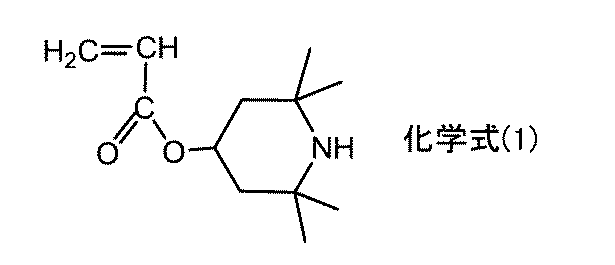

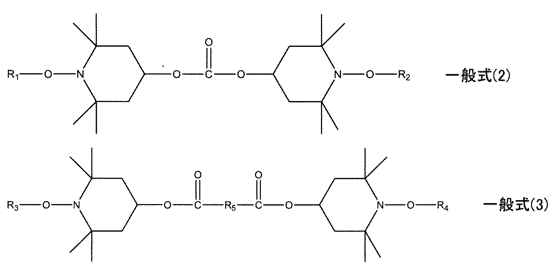
ポリオレフィン膜は、必要に応じて、上記の他にも添加剤を含有することができる。
ポリオレフィン膜の厚さは、封止性等の観点から、例えば下限値としては、10μm以上であることが好ましく、20μm以上であることがより好ましく、30μm以上であることがさらに好ましい。一方、上限値としては、300μm以下であることが好ましく、200μm以下であることがより好ましく、100μm以下であることがさらに好ましい。本形態においては、上述したように、ポリオレフィン膜がシラン変性樹脂を含有する場合には、密着性向上のためにシランカップリング剤を含有させる必要が無いため、ポリオレフィン膜の厚さを薄くすることができる。一方、ポリオレフィン膜が厚すぎると、太陽電池モジュールの薄型化、軽量化が困難になる場合がある。
本実施態様においては、封止材層が、ポリオレフィン膜よりも絶縁性基材側にポリプロピレン膜を有することが好ましい。例えば図2においては、封止材層2は、ポリオレフィン膜2aよりも絶縁性基材3側にポリプロピレン膜2bを有している。封止材層がポリプロピレン膜を有することにより、封止材フィルムとして利用可能な剛性を有する封止材層とすることができる。そのため、上記ポリオレフィン膜の厚さが薄い場合であっても、封止材層がポリプロピレン膜を有することにより、封止材層の取扱性を良くすることができる。さらには、太陽電池モジュール用絶縁フィルムの寸法安定性を高めることができる。
(i)ポリプロピレン樹脂
ポリプロピレン膜は、ポリプロピレン樹脂を含有する。ポリプロピレン樹脂としては、例えば、プロピレン単独重合体であるホモポリプロピレン樹脂であってもよく、プロピレンとα-オレフィンとのランダム共重合体であるランダムポリプロピレン樹脂であってもよく、ブロック共重合体であるブロックポリプロピレン樹脂であってもよい。ポリプロピレン膜は、上述した各種ポリプロピレン樹脂の1種単独または2種以上を含んでいてもよい。中でも、ポリプロピレン樹脂がホモポリプロピレン樹脂であることが好ましい。ホモポリプロピレン樹脂は剛性が高いことから、たとえ上記ポリオレフィン膜の厚さが薄い場合であっても、封止材層の取扱性を良くすることができる。さらには、太陽電池モジュール用絶縁フィルムの寸法安定性を高めることができる。
本形態において、ポリプロピレン膜は、上記ポリエチレン膜との密着性を向上させるために、密着性向上剤を含有することが好ましい。密着性向上剤としては、例えば、ポリエチレン系エラストマーやポリエチレン系プラストマー等を挙げることができる。本形態においては、ポリエチレン系エラストマーやポリエチレン系プラストマーをポリプロピレン膜に含有させることにより、上記ポリエチレン膜との密着性を向上させるばかりでなく、封止材層の耐久性を向上させることができる。
また、ポリプロピレン膜は、光安定剤を含有していてもよい。ポリプロピレン膜が光安定剤を含有することで、ポリプロピレン膜の紫外線劣化を抑制することができる。光安定剤としては、例えば、ヒンダードアミン系光安定剤(HALS)を用いることが好ましい。
また、ポリプロピレン膜は、ポリプロピレン系エラストマー(PP系エラストマー)をさらに含有していてもよい。ポリプロピレン膜がポリプロピレン系エラストマーを含有することにより、ポリプロピレン膜の透明性を高くすることができる。
ポリプロピレン膜は、必要に応じて、上記の他にも添加剤を含有することができる。
ポリプロピレン膜は、表面処理が施されていてもよい。ポリプロピレン膜の絶縁性基材側の面に表面処理が施されている場合には、第2の接着層に対する密着性を高めることができる。
本実施態様における封止材層の厚さは、例えば下限値としては、50μm以上とすることができ、30μm以上であることが好ましく、50μm以上であることがより好ましい。一方、上限値としては、400μm以下とすることができ、300μm以下であることが好ましく、200μm以下であることがより好ましい。本形態においては、上述したように、封止材層を構成するポリオレフィン膜がシラン変性樹脂を含有する場合には、密着性向上のためにシランカップリング剤を含有させる必要が無いため、ポリオレフィン膜の厚さを薄くすることができる。その結果、封止材層の厚さも薄くすることができる。
本実施態様の太陽電池モジュール用絶縁フィルムは、絶縁性基材およびポリエチレン系樹脂層の間に第1の接着層を有することができる。第1の接着層は、絶縁性基材およびポリエチレン系樹脂層を接着させる層である。
このようなポリイソシアネート化合物としては、主剤のポリウレタンジオールを架橋することができるものであれば特に限定されず、例えば、ポリウレタンジイソシアネート、ヘキサメチレンジイソシアネート、イソシアヌレート変性のイソホロンジイソシアネート等を挙げることができる。
本実施態様の太陽電池モジュール用絶縁フィルムは、絶縁性基材および封止材層の間に第2の接着層を有することができる。第2の接着層は、絶縁性基材および封止材層を接着させる層である。
本実施態様においては、太陽電池モジュール用絶縁フィルムのポリエチレン系樹脂層側の面を鋼板に熱圧着したときの、ポリエチレン系樹脂層の鋼板に対する密着力が、例えば、3N/15mm以上であることが好ましく、5N/15mm以上であることがより好ましく、10N/15mm以上であることがさらに好ましい。上記密着力が上記範囲であることにより、本形態における太陽電池モジュール用絶縁フィルムを太陽電池モジュールに用いた場合に、太陽電池モジュール用絶縁フィルムと鋼板との密着性に優れることから、太陽電池モジュールの信頼性や耐久性を向上させることができる。
密着性試験においては、75mm×100mmの大きさにカットした太陽電池モジュール用絶縁フィルムの試験片と、厚さ0.35mm、大きさ75mm×50mmのアクリル系塗装鋼板とを用いる。まず、上記太陽電池モジュール用絶縁フィルムの試験片を、太陽電池モジュール用絶縁フィルムのポリエチレン系樹脂層側の面を上記塗装鋼板側に向けて、上記塗装鋼板の塗装面に密着させる。また、上記塗装鋼板と上記太陽電池モジュール用絶縁フィルムとの間の一部に、大きさ75mm×60mmの離型フィルム(例えば、エチレン・テトラフルオロエチレン共重合体(ETFE)フィルム)を挿入する。次に、下記のラミネート条件で、真空ラミネータによる熱圧着を行う。その後、上記離型フィルムを取り除き、下記の剥離試験の剥離のきっかけを作る。次いで、上記塗装鋼板に密着している上記太陽電池モジュール用絶縁フィルムの試験片に対して、剥離試験機を用いて、剥離速度50mm/minで180度剥離試験を行い、密着力を測定する。上記密着力の測定方法の詳細については、実施例に記載の通りである。
(熱ラミネート条件)
・真空引き:5分間
・加圧:0kPaから100kPaまで、1分30秒かけて圧力を上昇した
・圧力保持(100kPa):7.5分間
・温度:150℃
本形態における太陽電池モジュール用絶縁フィルムの第2実施態様は、封止材層と、絶縁性基材と、ポリエチレン系樹脂層とをこの順に有し、上記ポリエチレン系樹脂層の厚さが、30μm以上300μm以下であり、上記ポリエチレン系樹脂層の上記絶縁性基材とは反対側の表面の濡れ張力が、36dyne/cm以上である。
本形態における鋼板付き絶縁フィルムは、上述の太陽電池モジュール用絶縁フィルムと、上記太陽電池モジュール用絶縁フィルムのポリエチレン系樹脂層側の面に配置された鋼板と、を有する。
本形態における太陽電池モジュール用絶縁フィルムについては、上記の「A.太陽電池モジュール用絶縁フィルム」の項に記載した内容と同様であるため、ここでの説明は省略する。
本形態における鋼板は、上記太陽電池モジュール用絶縁フィルムのポリエチレン系樹脂層側の面に配置される部材である。
本形態における鋼板付き絶縁フィルムの製造方法としては、例えば、離型フィルムと、太陽電池モジュール用絶縁フィルムと、鋼板とを有する積層体を熱圧着して一体化する方法が挙げられる。熱圧着の方法としては、例えば、真空熱ラミネート法を挙げることができる。離型フィルムとしては、例えば、エチレン・テトラフルオロエチレン共重合体(ETFE)フィルムや、離型ポリエチレンテレフタレート(PET)フィルム等が用いられる。
本形態における太陽電池モジュールは、透明基板と、封止材シートと、太陽電池セルと、上述の太陽電池モジュール用絶縁フィルムと、鋼板と、をこの順に有する。
本形態における太陽電池モジュール用絶縁フィルムについては、上記の「A.太陽電池モジュール用絶縁フィルム」の項に記載した内容と同様であるため、ここでの説明は省略する。
本形態における鋼板については、上記の「B.鋼板付き絶縁性フィルム」の項に記載した鋼板と同様であるため、ここでの説明は省略する。
本形態における太陽電池セルとしては、特に限定されるものではなく、例えば、単結晶シリコン太陽電池セル、多結晶シリコン太陽電池セル、アモルファスシリコン太陽電池セル、化合物半導体系太陽電池セル、色素増感型太陽電池セル、量子ドット型太陽電池セル、有機薄膜型太陽電池セル等が挙げられる。
本形態における透明基板は、太陽電池セルを保護する部材である。また、透明基板は、太陽電池セルの受光面側に配置され、表面保護部材として機能する。透明基板の透明性は、太陽電池セルの発電を阻害しない程度であれば特に限定されない。透明基板としては、一般的な太陽電池モジュールに用いられる透明基板と同様とすることができるため、ここでの説明は省略する。
本形態における封止材シートは、太陽電池セルを封止する部材である。封止材シートは、太陽電池セルの受光面側に配置される。
本形態における太陽電池モジュールの製造方法としては、特に限定されるものではなく、例えば、透明基板と、封止材シートと、太陽電池セルと、太陽電池モジュール用絶縁フィルムと、鋼板とを有する積層体を熱圧着して一体化する方法が挙げられる。熱圧着の方法としては、例えば、真空熱ラミネート法を挙げることができる。
次に、本開示における第2の形態の太陽電池モジュール用絶縁フィルム、配線シート付き絶縁フィルム、および太陽電池モジュールについて詳細に説明する。
本形態における太陽電池モジュール用絶縁フィルムは、太陽電池モジュールにおける太陽電池セルと配線シートとの間に配置される部材であり、絶縁性基材と、ポリエチレン膜を有する配線シート側封止材層と、を少なくとも有する。本形態における太陽電池モジュール用絶縁フィルムは、4つの実施態様を有する。以下、各実施態様に分けて説明する。
本形態における太陽電池モジュール用絶縁フィルムの第1実施態様は、150℃で30分間保持したときの、MD方向の熱収縮率が2.0%以下であり、TD方向の熱収縮率が1.5%以下である絶縁性基材と、上記絶縁性基材の一方の面に配置され、ポリエチレン膜を有する配線シート側封止材層と、を有し、上記ポリエチレン膜の上記絶縁性基材とは反対側の表面の濡れ張力が、36dyne/cm以上である。
本実施態様における配線シート側封止材層は、絶縁性基材の一方の面に配置され、ポリエチレン膜を少なくとも有する。また、ポリエチレン膜の絶縁性基材とは反対側の表面の濡れ張力は所定の値以上である。
本実施態様におけるポリエチレン膜は、配線シート側封止材層を構成する部材であり、配線シート側封止材層において、絶縁性基材とは反対側の面の最表面に配置される部材である。
本実施態様において、ポリエチレン膜の絶縁性基材とは反対側の表面の濡れ張力は、36dyne/cm以上であり、好ましくは40dyne/cm以上、より好ましくは46dyne/cm以上とすることができる。上記濡れ張力が上記範囲であることにより、配線シートの配線に対する密着性を向上させることができる。一方、上記濡れ張力は大きいほど好ましく、上記濡れ張力の上限は特に限定されない。
さらに、架橋型の封止材シートが、架橋剤に加えてシランカップリング剤を含有する場合において、封止材シートと絶縁性基材と封止材シートとをドライラミネート法により積層すると、ドライラミネート用接着剤を塗布した後、ドライラミネート用接着剤に含まれる溶剤を乾燥する際に、架橋型の封止材シートに含まれる架橋剤やシランカップリング剤が揮発してしまう。そのため、架橋型の封止材シートと絶縁性基材と架橋型の封止材シートとをドライラミネート法により積層するのは困難である。
また、非架橋型のポリエチレン膜であれば、架橋剤を含有せず、本実施態様ではシランカップリング剤を含有する必要が無いため、ドライラミネート法により積層する場合に好適である。
(i)ポリエチレン系樹脂
ポリエチレン膜は、ポリエチレン系樹脂を含有する。
本形態における上記ポリエチレン系樹脂の組成、密度、および融点については、「ア.第1の形態 A.太陽電池モジュール用絶縁フィルム I.第1実施態様 1.ポリエチレン系樹脂層」において、ポリエチレン系樹脂層に用いられるポリエチレン系樹脂での説明と同じであるため、ここでの説明は、省略する。
また、ポリエチレン膜の樹脂成分に関する点についても、「ア.第1の形態 A.太陽電池モジュール用絶縁フィルム I.第1実施態様 1.ポリエチレン系樹脂層」でのポリエチレン系樹脂層の説明と同じであるので、ここでの説明は、省略する。
本実施態様において、ポリエチレン膜は、シラン変性樹脂を含有することが好ましい。ポリエチレン膜がシラン変性樹脂を含有することにより、配線シートの配線に対する密着性や、強度、耐久性等を向上させることができる。
また、ポリエチレン膜は、光安定剤を含有していてもよい。ポリエチレン膜が光安定剤を含有することで、ポリエチレン膜の紫外線劣化を抑制することができる。光安定剤としては、例えば、ヒンダードアミン系光安定剤(HALS)を用いることが好ましい。
ポリエチレン膜は、必要に応じて、上記の他にも添加剤を含有することができる。
ポリエチレン膜の厚さは、封止性等の観点から、例えば下限値が、10μm以上であることが好ましく、20μm以上であることがより好ましく、30μm以上であることがさらに好ましい。一方、上限値としては、300μm以下であることが好ましく、200μm以下であることがより好ましく、100μm以下であることがさらに好ましい。本実施態様においては、上述したように、ポリエチレン膜がシラン変性樹脂を含有する場合には、密着性向上のためにシランカップリング剤を含有させる必要が無いため、ポリエチレン膜の厚さを薄くすることができる。一方、ポリエチレン膜の厚さが厚すぎると、後述するように太陽電池モジュール用絶縁フィルムが貫通孔を有する場合に、貫通孔を形成するのが困難になる可能性がある。
本実施態様においては、配線シート側封止材層が、ポリエチレン膜と絶縁性基材との間にポリプロピレン膜を有することが好ましい。例えば図6においては、配線シート側封止材層103は、ポリエチレン膜103aと絶縁性基材102との間にポリプロピレン膜103bを有している。配線シート側封止材層がポリプロピレン膜を有することにより、封止材フィルムとして利用可能な剛性を有する配線シート側封止材層とすることができる。そのため、上記ポリエチレン膜の厚さが薄い場合であっても、配線シート側封止材層がポリプロピレン膜を有することにより、配線シート側封止材層の取扱性を良くすることができる。さらには、太陽電池モジュール用絶縁フィルムの寸法安定性を高めることができる。
(i)ポリプロピレン樹脂
ポリプロピレン膜は、ポリプロピレン樹脂を含有する。
本形態に用いられるポリプロピレン樹脂については、「ア.第1の形態 A.太陽電池モジュール用絶縁フィルム I.第1実施態様 (2)ポリプロピレン膜 (i)ポリプロピレン樹脂」での説明と同じであるので、ここでの説明は省略する。
本実施態様において、ポリプロピレン膜は、上記ポリエチレン膜との密着性を向上させるために、密着性向上剤を含有することが好ましい。
本形態に用いられる密着性向上剤については、「ア.第1の形態 A.太陽電池モジュール用絶縁フィルム I.第1実施態様 (2)ポリプロピレン膜 (ii)密着性向上剤」での説明と同じであるので、ここでの説明は省略する。
また、ポリプロピレン膜は、光安定剤を含有していてもよい。
本形態におけるポリプロピレン膜に用いられる光安定剤については、「ア.第1の形態 A.太陽電池モジュール用絶縁フィルム I.第1実施態様 (2)ポリプロピレン膜 (iii)光安定剤」での説明と同じであるので、ここでの説明は省略する。
また、ポリプロピレン膜は、ポリプロピレン系エラストマー(PP系エラストマー)をさらに含有していてもよい。ポリプロピレン膜がポリプロピレン系エラストマーを含有することにより、ポリプロピレン膜の透明性を高くすることができる。
ポリプロピレン膜は、必要に応じて、上記の他にも添加剤を含有することができる。
ポリプロピレン膜は、表面処理が施されていてもよい。ポリプロピレン膜の絶縁性基材側の面に表面処理が施されている場合には、第1の接着層に対する密着性を高めることができる。
本実施態様における配線シート側封止材層の厚さは、例えば下限値としては、30μm以上とすることができ、50μm以上であることがより好ましい。一方上限値としては、400μm以下とすることができ、300μm以下であることが好ましく、200μm以下であることがより好ましい。本実施態様においては、上述したように、ポリエチレン膜がシラン変性樹脂を含有する場合には、密着性向上のためにシランカップリング剤を含有させる必要が無いため、ポリエチレン膜の厚さを薄くすることができる。その結果、配線シート側封止材層の厚さも薄くすることができる。
本実施態様における絶縁性基材においては、150℃で30分間保持したときのMD方向およびTD方向の寸法変化の割合(熱収縮率)がそれぞれ所定の値以下である。
(熱処理後寸法-熱処理前寸法)/熱処理前寸法×100%
本形態における絶縁性基材に用いられる着色剤については、「ア.第1の形態 A.太陽電池モジュール用絶縁フィルム I.第1実施態様 2.絶縁性基材」における絶縁性基材に用いられる着色剤の説明と同じであるので、ここでの説明は、省略する。
本実施態様の太陽電池モジュール用絶縁フィルムは、上記絶縁性基材の上記ポリエチレン膜とは反対の面に、太陽電池セル側封止材層を有することが好ましい。
すなわち、ポリオレフィン膜のゲル分率は0%であることが好ましい。
本実施態様におけるポリオレフィン膜は、太陽電池セル側封止材層を構成する部材であり、太陽電池セル側封止材層において、絶縁性基材とは反対側の面の最表面に配置される部材である。
(a)ポリオレフィン系樹脂
ポリオレフィン膜は、ポリオレフィン系樹脂を含有する。ポリオレフィン系樹脂としては、太陽電池モジュールの封止材として使用可能なものであれば特に限定されないが、中でも、上述の理由から、非架橋型のポリオレフィン系樹脂であることが好ましい。非架橋型のポリオレフィン系樹脂としては、例えば、ポリエチレン系樹脂、ポリプロピレン系樹脂、プロピレン-エチレン共重合樹脂、エチレン-αオレフィン共重合樹脂等が挙げられる。中でも、ポリエチレン系樹脂が好ましい。すなわち、ポリオレフィン膜は、ポリエチレン膜であることが好ましい。ポリエチレン系樹脂は、封止性に優れるからである。
また、上記ポリオレフィン系樹脂の割合は、例えば、99質量%以下であり、95質量%以下であってもよく、90質量%以下であってもよい。なお、上記ポリオレフィン系樹脂の割合は、100質量%であってもよい。
本実施態様において、ポリオレフィン膜は、シラン変性樹脂を含有することが好ましい。ポリオレフィン膜がシラン変性樹脂を含有することにより、太陽電池セルに対する密着性や、強度、耐久性等を向上できる。さらに、ポリオレフィン膜がシラン変性樹脂を含有する場合には、密着性向上のためにシランカップリング剤を含有させる必要が無いため、ポリオレフィン膜の厚さを薄くすることができる。これにより、太陽電池モジュール用絶縁フィルム全体の厚さを薄くすることができる。そのため、本実施態様の太陽電池モジュール用絶縁フィルムを太陽電池モジュールに用いた場合には、太陽電池モジュール用絶縁フィルムの貫通孔内に配置され、太陽電池セルの電極と配線シートの配線とを電気的に接続する導通部の形成に用いられる導電性材料の使用量を低減することができ、製造コストを削減できる。また、本実施態様の太陽電池モジュール用絶縁フィルムを太陽電池モジュールに用いた場合には、太陽電池モジュールの薄型化、軽量化が可能である。
また、ポリオレフィン膜は、光安定剤を含有していてもよい。ポリオレフィン膜が光安定剤を含有することで、ポリオレフィン膜の紫外線劣化を抑制できる。光安定剤としては、上記配線シート側封止材層を構成するポリエチレン膜に用いられる光安定剤と同様とすることができるので、ここでの説明は省略する。
ポリオレフィン膜は、必要に応じて、上記の他にも添加剤を含有することができる。
ポリオレフィン膜の厚さとしては、上記配線シート側封止材層を構成するポリエチレン膜の厚さと同様とすることができるので、ここでの説明は省略する。
本実施態様においては、太陽電池セル側封止材層が、ポリオレフィン膜よりも絶縁性基材側にポリプロピレン膜を有することが好ましい。例えば図6においては、太陽電池セル側封止材層104は、ポリオレフィン膜104aと絶縁性基材102との間にポリプロピレン膜104bを有している。太陽電池セル側封止材層がポリプロピレン膜を有することにより、封止材フィルムとして利用可能な剛性を有する太陽電池セル側封止材層とすることができる。そのため、上記ポリオレフィン膜の厚さが薄い場合であっても、太陽電池セル側封止材層がポリプロピレン膜を有することにより、太陽電池セル側封止材層の取扱性を良くすることができる。さらには、太陽電池モジュール用絶縁フィルムの寸法安定性を高めることができる。
太陽電池セル側封止材層の厚さとしては、上記配線シート側封止材層の厚さと同様とすることができるので、ここでの説明は省略する。
本実施態様の太陽電池モジュール用絶縁フィルムは、絶縁性基材および配線シート側封止材層の間に第1の接着層を有することができる。第1の接着層は、絶縁性基材および配線シート側封止材層を接着させる層である。
本実施態様の太陽電池モジュール用絶縁フィルムは、絶縁性基材および太陽電池セル側封止材層の間に第2の接着層を有することができる。第2の接着層は、絶縁性基材および太陽電池セル側封止材層を接着させる層である。
本実施態様の太陽電池モジュール用絶縁フィルムは、太陽電池セルの電極および配線シートの配線に対応する位置に貫通孔を有することができる。例えば図7において、太陽電池モジュール用絶縁フィルム101は、所定の位置に複数の貫通孔7を有している。本実施態様の太陽電池モジュール用絶縁フィルムを用いた太陽電池モジュールにおいては、太陽電池モジュール用絶縁フィルムの貫通孔内に導通部を配置することで、導通部を介して太陽電池セルの電極および配線シートの配線を導通させることができる。
本実施態様においては、太陽電池モジュール用絶縁フィルムの配線シート側封止材層側の面を銅箔に熱圧着したときの、配線シート側封止材層の銅箔に対する密着力が、例えば、3N/15mm以上であることが好ましく、8N/15mm以上であることがより好ましく、10N/15mm以上であることがさらに好ましい。上記密着力が上記範囲であることにより、本実施態様の太陽電池モジュール用絶縁フィルムを太陽電池モジュールに用いた場合に、太陽電池モジュール用絶縁フィルムと配線シートとの密着性に優れることから、太陽電池モジュールの信頼性や耐久性を向上させることができる。
密着性試験においては、75mm×50mmの大きさにカットした太陽電池モジュール用絶縁フィルムの試験片と、厚さ35μm、大きさ75mm×50mmの銅箔と、大きさ75mm×50mmのガラス板と、厚さ450μm、大きさ75mm×50mm、直線状低密度ポリエチレン(LLDPE)をベース樹脂とする封止材シートとを用いる。まず、上記ガラス板上に、上記封止材シートと、上記太陽電池モジュール用絶縁フィルムの試験片と、上記銅箔とをこの順に積層する。この際、太陽電池モジュール用絶縁フィルムの配線シート側封止材層側の面を上記銅箔側に向けて、上記銅箔の一方の面に密着させる。また、上記銅箔と上記太陽電池モジュール用絶縁フィルムとの間の一部に、大きさ10mm×75mmの離型フィルム(例えば、エチレン・テトラフルオロエチレン共重合体(ETFE)フィルム)を挿入する。次に、下記のラミネート条件で、真空ラミネータによる熱圧着を行う。その後、上記離型フィルムを取り除き、下記の剥離試験の剥離のきっかけを作る。次いで、上記銅箔に密着している上記太陽電池モジュール用絶縁フィルムの試験片に対して、剥離試験機を用いて、剥離速度50mm/minで180度剥離試験を行い、密着力を測定する。上記密着力の測定方法の詳細については、実施例に記載の通りである。
(熱ラミネート条件)
・真空引き:5分間
・加圧:0kPaから100kPaまで、1分30秒かけて圧力を上昇した
・圧力保持(100kPa):7.5分間
・温度:150℃
本形態における太陽電池モジュール用絶縁フィルムの第2実施態様は、ポリエチレンテレフタレート、ポリエチレンナフタレート、ポリブチレンテレフタレート、ポリイミド、ポリアミド、ポリカーボネート、および変性ポリフェニレンエーテルからなる群から選択される少なくとも1種の樹脂を含有する絶縁性基材と、上記絶縁性基材の一方の面に配置され、ポリエチレン膜を有する配線シート側封止材層と、を有し、上記ポリエチレン膜の上記絶縁性基材とは反対側の表面の濡れ張力が、36dyne/cm以上である。
本形態における太陽電池モジュール用絶縁フィルムの第3実施態様は、150℃で30分間保持したときの、MD方向の熱収縮率が2.0%以下であり、TD方向の熱収縮率が1.5%以下である絶縁性基材と、上記絶縁性基材の一方の面に配置され、シラン変性樹脂を含有するポリエチレン膜を有する配線シート側封止材層と、を有し、上記ポリエチレン膜中のケイ素原子の含有量が0.0001質量%以上15.0質量%以下である。
本形態における太陽電池モジュール用絶縁フィルムの第4実施態様は、ポリエチレンテレフタレート、ポリエチレンナフタレート、ポリブチレンテレフタレート、ポリイミド、ポリアミド、ポリカーボネート、および変性ポリフェニレンエーテルからなる群から選択される少なくとも1種の樹脂を含有する絶縁性基材と、上記絶縁性基材の一方の面に配置され、シラン変性樹脂を含有するポリエチレン膜を有する配線シート側封止材層と、を有し、上記ポリエチレン膜中のケイ素原子の含有量が0.0001質量%以上15.0質量%以下である。
本形態における配線シート付き絶縁フィルムは、上述の太陽電池モジュール用絶縁フィルムと、上記太陽電池モジュール用絶縁フィルムの配線シート側封止材層側の面に配置された配線シートと、を有する。
図8に示すように、配線シート付き絶縁フィルム110は、太陽電池モジュール用絶縁フィルム101と、太陽電池モジュール用絶縁フィルム101の配線シート側封止材層103側の面に配置された配線シート111と、有する。太陽電池モジュール用絶縁フィルム101の構成は、上述の図5に示す太陽電池モジュール用絶縁フィルム101と同様である。
本形態における太陽電池モジュール用絶縁フィルムについては、上記の「A.太陽電池モジュール用絶縁フィルム」の項に記載した内容と同様であるため、ここでの説明は省略する。
本形態における配線シートは、上記太陽電池モジュール用絶縁フィルムの配線シート側封止材層側の面に配置される部材である。配線シートは、基材と、基材の一方の面に配置されたパターン状の配線と、を有することができる。
配線シートを構成する配線の材料としては、例えば、銅、金、アルミニウム等の金属、これらの金属を含む合金等が挙げられる。中でも、導電性およびコストの観点から、銅が好ましい。また、配線の形成には、例えば金属箔を用いることができる。
配線シートを構成する基材は、絶縁性を有する基材であり、例えば樹脂基材を用いることができる。樹脂基材を構成する樹脂としては、例えば、ポリエチレン系樹脂、ポリプロピレン系樹脂、環状ポリオレフィン系樹脂、ポリスチレン系樹脂、アクリロニトリル-スチレン共重合体、アクリロニトリル-ブタジエン-スチレン共重合体、ポリ塩化ビニル系樹脂、フッ素系樹脂、ポリ(メタ)アクリル系樹脂、ポリカーボネート系樹脂、ポリエステル系樹脂、ポリアミド系樹脂、ポリイミド系樹脂、ポリアミドイミド系樹脂、ポリアリールフタレート系樹脂、シリコーン系樹脂、ポリスルホン系樹脂、ポリフェニレンスルフィド系樹脂、ポリエーテルスルホン系樹脂、ポリウレタン系樹脂、アセタール系樹脂、セルロース系樹脂等が挙げられる。ポリエステル系樹脂としては、例えば、ポリエチレンテレフタレート(PET)やポリエチレンナフタレート(PEN)、が挙げられる。ポリアミド系樹脂としては、例えば、各種のナイロンが挙げられる。
本形態における配線シート付き絶縁フィルムは、上記配線シートの上記太陽電池モジュール用絶縁フィルムとは反対側の面に裏面保護シートを有していてもよい。
本形態における配線シート付き絶縁フィルムの製造方法としては、例えば、離型フィルムと、太陽電池モジュール用絶縁フィルムと、配線シートとを有する積層体を熱圧着して一体化する方法が挙げられる。熱圧着の方法としては、例えば、真空熱ラミネート法を挙げることができる。離型フィルムとしては、例えば、エチレン・テトラフルオロエチレン共重合体(ETFE)フィルムや、離型ポリエチレンテレフタレート(PET)フィルム等が用いられる。
本形態における太陽電池モジュールは、透明基板と、封止材シートと、太陽電池セルと、上述の太陽電池モジュール用絶縁フィルムと、配線シートと、をこの順に有する。
本形態における太陽電池モジュール用絶縁フィルムについては、上記の「A.太陽電池モジュール用絶縁フィルム」の項に記載した内容と同様であるため、ここでの説明は省略する。
本形態における配線シートについては、上記の「B.配線シート付き絶縁性フィルム」の項に記載した配線シートと同様であるため、ここでの説明は省略する。
本形態における太陽電池セルとしては、特に限定されるものではなく、例えば、IBC(Interdigitated Back Contact)型の太陽電池セル、MWT(Metal Wrap Through)型の太陽電池セル、EWT(Emitter Wrap Through)型の太陽電池セル等を挙げることができる。
本形態における導通部は、太陽電池モジュール用絶縁フィルムの貫通孔内に配置され、太陽電池セルの電極と配線シートの配線とを電気的に接続する部材である。
本形態における透明基板は、太陽電池セルを保護する部材である。また、透明基板は、太陽電池セルの受光面側に配置され、表面保護部材として機能する。透明基板の透明性は、太陽電池セルの発電を阻害しない程度であれば特に限定されない。透明基板としては、一般的な太陽電池モジュールに用いられる透明基板と同様とすることができるため、ここでの説明は省略する。
本形態における封止材シートは、太陽電池セルを封止する部材である。封止材シートは、太陽電池セルの受光面側に配置される。
本形態における太陽電池モジュールは、上記配線シートの上記太陽電池モジュール用絶縁フィルムとは反対側の面に裏面保護シートを有していてもよい。
本形態における太陽電池モジュールの製造方法としては、特に限定されるものではなく、例えば、まず、太陽電池セルの裏面電極上に導電性材料を配置する。次に、透明基板と、封止材シートと、導電性材料が配置された太陽電池セルと、貫通孔を有する太陽電池モジュール用絶縁フィルムと、配線シートとを有する積層体を熱圧着して一体化する方法が挙げられる。この熱圧着の際に、封止材シートと太陽電池モジュール用絶縁フィルムの配線シート側封止材層および太陽電池セル側封止材層とが軟化するとともに、導電性材料が溶融する。そのため、太陽電池モジュール用絶縁フィルムの貫通孔内が導電性材料で充填され、太陽電池セルの電極と配線シートの配線とを電気的に接続できる。熱圧着の方法としては、例えば、真空熱ラミネート法を挙げることができる。
以下、第1の形態について、実施例を用いて説明する。
[実施例A-1~A-4]
(1)材料の準備
絶縁性基材として、厚さ150μmのポリエチレンテレフタレート(PET)フィルム(DuPont Hongji Films Foshan社製、AP)を用い、ポリエチレンフィルムとして、厚さ60μmの片面がコロナ処理されたポリエチレンフィルム(タマポリ社製、SE625N)を用い、ドライラミネート用接着剤として、2液型接着剤(ロックペイント社製、主剤:KT-0035、硬化剤:H-039Z2)を用いた。なお、上記ポリエチレンフィルムのコロナ処理面の濡れ張力は54dyne/cmであった。
ポリエチレン膜を形成するための下記組成のポリエチレン樹脂組成物を調製した。
・エチレン-α-オレフィン共重合体(日本ポリエチレン社製「カーネルKF260T」、密度0.9g/cm3、融点93℃、MFR(A法、190℃、2.16kgf)2.0g/10min):84質量部
・シラン変性ポリエチレン樹脂(三菱ケミカル社製「リンクロンMF900N」、密度0.9g/cm3、融点83℃、MFR(A法、190℃、2.16kgf)1.0g/10min):15質量部・耐候剤(HALS)マスターバッチ:1質量部
・ホモポリプロピレン(プライムポリマー社製、「S135」、密度0.9g/cm3、融点165℃、MFR(A法、190℃、2.16kgf)4.0g/10min):63質量部
・ポリプロピレン系エラストマー(三井化学社製、「タフマーPN2060」、密度0.868g/cm3、融点160℃、MFR(190℃)4.0g/10min):10質量部
・密着性向上剤(ポリエチレン系エラストマー(エチレン-α-オレフィン共重合体)、三井化学社製、「タフマーDF110」、密度0.905g/cm3、融点94℃、MFR(A法、190℃、2.16kgf)1.2g/10min):19質量部
・耐候剤(HALS)マスターバッチ:8質量部
上記絶縁性基材の一方の面に上記ドライラミネート用接着剤を5g/m2塗布し、上記ポリエチレンフィルムのコロナ処理面と貼り合わせ、また、上記絶縁性基材の他方の面に同様に上記ドライラミネート用接着剤を5g/m2塗布し、上記封止材層のコロナ処理面と貼り合わせて、積層体を得た。次いで、積層体に対して50℃で1週間エージングを行い、上記ドライラミネート用接着剤を硬化させた。次に、積層体のポリエチレンフィルムの面に、下記表1に示す濡れ張力となるように、コロナ処理を行った。
実施例A-1において、積層体を得た後に、積層体のポリエチレンフィルムの面にコロナ処理を施さなかったこと以外は、実施例A-1と同様にして太陽電池モジュール用絶縁フィルムを作製した。
実施例A-1において、積層体のポリエチレンフィルムの面に対するコロナ処理について、ポリエチレンフィルム表面の濡れ張力が下記表1に示す値となるように、コロナ処理を行ったこと以外は、実施例A-1と同様にして太陽電池モジュール用絶縁フィルムを作製した。
太陽電池モジュール用絶縁フィルムとして、厚さ450μmの封止材シート(3M社製、fast cure EVA)を単体で用いた。
(1)濡れ張力
ポリエチレン系樹脂層の絶縁性基材とは反対側の表面の濡れ張力は、JIS K6768(プラスチック フィルム及びシート ぬれ張力試験方法)に準拠して測定した。濡れ張力の測定に際しては、和光純薬社製のぬれ張力試験用混合液を用いた。
実施例および比較例の太陽電池モジュール用絶縁フィルムに対して密着性試験を行い、鋼板に対する密着力を測定した。密着性試験においては、75mm×100mmの大きさにカットした太陽電池モジュール用絶縁フィルムの試験片を用いた。また、鋼板として、厚さ0.35mm、大きさ75mm×50mmであり、アクリル系塗装鋼板(日本鋼板社製、ガルバリウム鋼板「リファーナ」)を用いた。まず、太陽電池モジュール用絶縁フィルムの試験片を、鋼板の塗装面に密着させた。この際、実施例A-1~A-4および比較例A-1~A-2については、太陽電池モジュール用絶縁フィルムのポリエチレンフィルム側の面を鋼板側に向けて、鋼板の塗装面に密着させた。また、鋼板と太陽電池モジュール用絶縁フィルムとの間の一部に、大きさ75mm×60mmのエチレン・テトラフルオロエチレン共重合体(ETFE)フィルムを挿入した。次に、下記のラミネート条件で、真空ラミネータによる熱圧着を行った。その後、ETFEフィルムを取り除き、下記の剥離試験の剥離のきっかけを作った。次いで、鋼板に密着している太陽電池モジュール用絶縁フィルムの試験片に対して、剥離試験機(A&D社製のテンシロン引張試験機)を用いて、剥離速度50mm/minで180度剥離試験を行い、密着力を測定した。
(熱ラミネート条件)
・真空引き:5分間
・加圧:0kPaから100kPaまで、1分30秒かけて圧力を上昇した
・圧力保持(100kPa):7.5分間
・温度:150℃
実施例および比較例の太陽電池モジュール用絶縁フィルムについて、絶縁性を評価した。具体的には、上記の密着性試験を行い、ラミネート後も絶縁性が十分に得られるものを「A」、ラミネート時に太陽電池モジュール用絶縁フィルムの厚さが薄くなり、絶縁性が不足するものを「F」とした。
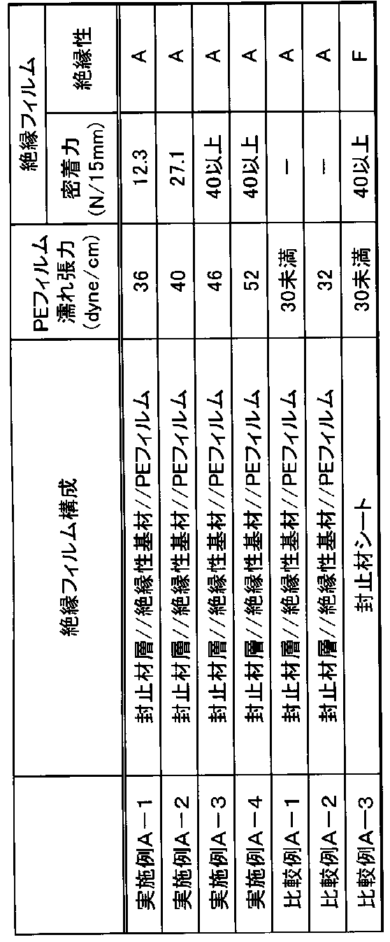
絶縁性基材として、厚さ50μmの白色ポリエチレンテレフタレート(PET)フィルム(DuPont Hongji Films Foshan社製、BP-D)を用い、ポリエチレンフィルムとして、厚さ60μmの片面がコロナ処理されたポリエチレンフィルム(タマポリ社製、SE625N)を用いた。また、実施例A-1~A-4と同様にして、封止材層を作製した。
次に、第2の形態について、実施例を用いて説明する。
(1)太陽電池セル側封止材層および配線シート側封止材層の作製
ポリエチレン膜を形成するための下記組成のポリエチレン樹脂組成物を調製した。
・エチレン-α-オレフィン共重合体(日本ポリエチレン社製「カーネルKF260T」、密度0.9g/cm3、融点93℃、MFR(190℃)2.0g/10min):94質量部
・シラン変性ポリエチレン樹脂(三菱ケミカル社製「リンクロンMF900N」、密度0.9g/cm3、融点83℃、MFR(190℃)1.0g/10min):5質量部
・耐候剤(HALS)マスターバッチ:1質量部
・ホモポリプロピレン(プライムポリマー社製、「S135」、密度0.9g/cm3、融点165℃、MFR(190℃)4.0g/10min):63質量部
・ポリプロピレン系エラストマー(三井化学社製、「タフマーPN2060」、密度0.868g/cm3、融点160℃、MFR(A法、190℃、2.16kgf)4.0g/10min):10質量部
・密着性向上剤(ポリエチレン系エラストマー(エチレン-α-オレフィン共重合体)、三井化学社製、「タフマーDF110」、密度0.905g/cm3、融点94℃、MFR(A法、190℃、2.16kgf)1.2g/10min):19質量部
・耐候剤(HALS)マスターバッチ:8質量部
絶縁性基材として、厚さ50μmの白色ポリエチレンテレフタレート(PET)フィルム(DuPont Hongji Films Foshan社製、BP-D)を用いた。
ポリエチレン膜の形成について、下記組成のポリエチレン樹脂組成物を用いたこと以外は、実施例B-1と同様に、太陽電池モジュール用絶縁フィルムを作製した。
・エチレン-α-オレフィン共重合体(日本ポリエチレン社製「カーネルKF260T」、密度0.9g/cm3、融点93℃、MFR(A法、190℃、2.16kgf)2.0g/10min):84質量部
・シラン変性ポリエチレン樹脂(三菱ケミカル社製「リンクロンMF900N」、密度0.9g/cm3、融点83℃、MFR(A法、190℃、2.16kgf)1.0g/10min):15質量部・耐候剤(HALS)マスターバッチ:1質量部
ポリエチレン膜の形成について、下記組成のポリエチレン樹脂組成物を用いたこと以外は、実施例B-1と同様に、太陽電池モジュール用絶縁フィルムを作製した。
・エチレン-α-オレフィン共重合体(日本ポリエチレン社製「カーネルKF260T」、密度0.9g/cm3、融点93℃、MFR(A法、190℃、2.16kgf)2.0g/10min):50質量部
・シラン変性ポリエチレン樹脂(三菱ケミカル社製「リンクロンMF900N」、密度0.9g/cm3、融点83℃、MFR(A法、190℃、2.16kgf)1.0g/10min):50質量部・耐候剤(HALS)マスターバッチ:1質量部
実施例B-1において、絶縁性基材にアニール処理を施したこと以外は、実施例B-1と同様にして太陽電池モジュール用絶縁フィルムを作製した。
実施例B-1において、積層体の配線シート側封止材層の面にコロナ処理を施さなかったこと以外は、実施例B-1と同様にして太陽電池モジュール用絶縁フィルムを作製した。
実施例B-1において、太陽電池セル側封止材層および配線シート側封止材層として、厚さ450μmの封止材シート(3M社製、fast cure EVA)を用いたこと以外は、実施例B-1と同様にして太陽電池モジュール用絶縁フィルムを作製した。
太陽電池モジュール用絶縁フィルムとして、厚さ450μmの封止材シート(3M社製、fast cure EVA)を単体で用いた。
(1)配線シート側封止材層のポリエチレン膜の濡れ張力
ポリエチレン膜の絶縁性基材とは反対側の表面の濡れ張力は、JIS K6768-1999(プラスチック フィルム及びシート ぬれ張力試験方法)に準拠して測定した。濡れ張力の測定に際しては、和光純薬社製のぬれ張力試験用混合液を用いた。
ポリエチレン膜を硫酸中にて徐々に分解させた後、温度を上昇させ、乾式分解(アルカリ溶融処理含)にて処理を行い、定容した液を検液とした。ICP発光分光分析法(ICP-AES)にて検液中のSiを定量した。
絶縁性基材のMD方向およびTD方向の熱収縮率は、JIS-K-7133-1999に準拠して測定した。測定条件は、150℃、30分間とした。
JIS-K-8654-2-1999に準拠して測定し、下記式により算出した。
(熱処理後寸法-熱処理前寸法)/熱処理前寸法×100%
具体的には、実施例および比較例の太陽電池モジュール用絶縁フィルムの配線シート側封止材層に対して密着性試験を行い、配線シート側封止材層の銅箔に対する密着力を測定した。密着性試験においては、75mm×50mmの大きさにカットした太陽電池モジュール用絶縁フィルムの試験片と、厚さ35μm、大きさ75mm×50mmの銅箔と、大きさ75mm×50mmのガラス板と、厚さ450μm、大きさ775mm5mm×50mm、ポリエチレンをベース樹脂とする封止材シート(大日本印刷株式会社製、「CVF」)とを用いた。まず、上記ガラス板上に、上記封止材シートと、上記太陽電池モジュール用絶縁フィルムの試験片と、上記銅箔と、をこの順に積層した。この際、太陽電池モジュール用絶縁フィルムの配線シート側封止材層側の面を上記銅箔側に向けて、上記銅箔の一方の面に密着させた。また、上記銅箔と上記太陽電池モジュール用絶縁フィルムとの間の一部に、大きさ10mm×75mmのETFEフィルム挿入した。次に、下記のラミネート条件で、真空ラミネータによる熱圧着を行った。その後、上記離型フィルムを取り除き、下記の剥離試験の剥離のきっかけを作った。次いで、銅箔に密着している太陽電池モジュール用絶縁フィルムの試験片に対して、剥離試験機(A&D社製のテンシロン引張試験機)を用いて、剥離速度50mm/minで180度剥離試験を行い、密着力を測定した。
・真空引き:5分間
・加圧:0kPaから100kPaまで、1分30秒かけて圧力を上昇した
・圧力保持(100kPa):7.5分間
・温度:150℃
絶縁フィルムのMD方向およびTD方向の熱収縮率は、JIS K7133―1999に準拠して測定した。測定条件は、150℃、30分間とした。
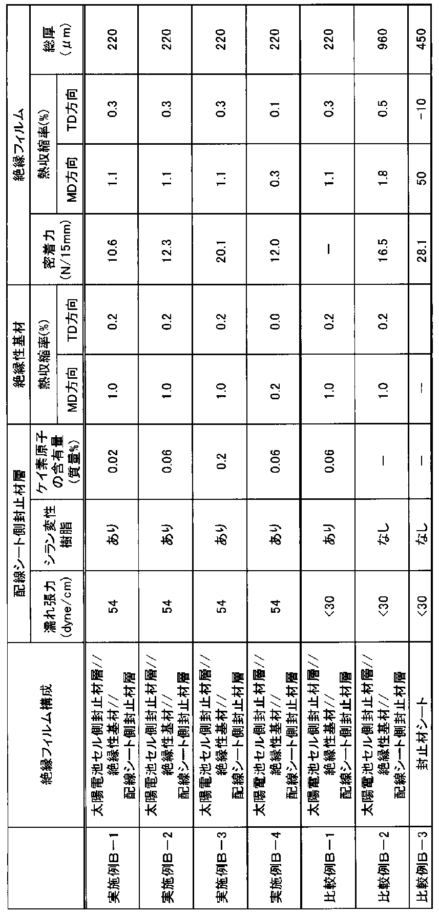
実施例B-1において配線シート側封止材層として用いたポリエチレン膜を用い、ポリエチレン膜に対して処理条件を変えてコロナ処理を施した。コロナ処理後のポリエチレン膜について、上記と同様にして濡れ張力および密着力を測定した。結果を表3に示す。

太陽電池モジュールにおける太陽電池セルと鋼板との間に配置される太陽電池モジュール用絶縁フィルムであって、
封止材層と、絶縁性基材と、ポリエチレン系樹脂層とをこの順に有し、
前記ポリエチレン系樹脂層がポリエチレンフィルムであり、
前記ポリエチレン系樹脂層の前記絶縁性基材とは反対側の表面の濡れ張力が、36dyne/cm以上である、太陽電池モジュール用絶縁フィルム。
太陽電池モジュールにおける太陽電池セルと鋼板との間に配置される太陽電池モジュール用絶縁フィルムであって、
封止材層と、絶縁性基材と、ポリエチレン系樹脂層とをこの順に有し、
前記ポリエチレン系樹脂層の厚さが、10μm以上300μm以下であり、
前記ポリエチレン系樹脂層の前記絶縁性基材とは反対側の表面の濡れ張力が、36dyne/cm以上である、太陽電池モジュール用絶縁フィルム。
前記絶縁性基材の厚さが25μm以上350μm以下である、[1]または[2]に記載の太陽電池モジュール用絶縁フィルム。
[4]
前記太陽電池モジュール用絶縁フィルムの前記ポリエチレン系樹脂層側の面を鋼板に熱圧着したときの、前記ポリエチレン系樹脂層の前記鋼板に対する密着力が10N/15mm以上である、[1]から[3]までのいずれかに記載の太陽電池モジュール用絶縁フィルム。
前記絶縁性基材が、ポリエチレンテレフタレート、ポリエチレンナフタレート、ポリブチレンテレフタレート、ポリイミド、ポリアミド、ポリカーボネート、および変性ポリフェニレンエーテルからなる群から選択される少なくとも1種の樹脂を含有する、[1]から[4]までのいずれかに記載の太陽電池モジュール用絶縁フィルム。
[6]
前記封止材層が、シラン変性樹脂を含有するポリオレフィン膜を有する、[1]から[5]までのいずれかに記載の太陽電池モジュール用絶縁フィルム。
前記ポリオレフィン膜がポリエチレン膜であり、前記封止材層が、前記ポリオレフィン膜と前記絶縁性基材との間にポリプロピレン膜を有する、[6]に記載の太陽電池モジュール用絶縁フィルム。
[8]
前記封止材層が、前記ポリエチレン膜および前記ポリプロピレン膜を有する共押出しフィルムを含む、[7]に記載の太陽電池モジュール用絶縁フィルム。
[9]
前記ポリプロピレン膜が、密着性向上剤を含有する、[7]または[8]に記載の太陽電池モジュール用絶縁フィルム。
前記封止材層の厚さが50μm以上400μm以下である、[1]から[9]までのいずれかに記載の太陽電池モジュール用絶縁フィルム。
[11]
前記絶縁性基材および前記ポリエチレン系樹脂層の間に第1の接着層を有する、[1]から[10]までのいずれかに記載の太陽電池モジュール用絶縁フィルム。
前記絶縁性基材および前記封止材層の間に第2の接着層を有する、[1]から[11]までのいずれかに記載の太陽電池モジュール用絶縁フィルム。
[13]
前記絶縁性基材が着色剤を含有する、[1]から[12]までのいずれかに記載の太陽電池モジュール用絶縁フィルム。
[14]
前記第2の接着層が着色剤を含有する、[12]に記載の太陽電池モジュール用絶縁フィルム。
[1]から[14]までのいずれかに記載の太陽電池モジュール用絶縁フィルムと、
前記太陽電池モジュール用絶縁フィルムのポリエチレン系樹脂層側の面に配置された鋼板と、
を有する鋼板付き絶縁フィルム。
[16]
透明基板と、封止材シートと、太陽電池セルと、[]1から[]14までのいずれかの[]に記載の太陽電池モジュール用絶縁フィルムと、鋼板と、をこの順に有する太陽電池モジュール。
太陽電池モジュールにおける太陽電池セルと配線シートとの間に配置される太陽電池モジュール用絶縁フィルムであって、
150℃で30分間保持したときの、MD方向の熱収縮率が2.0%以下であり、TD方向の熱収縮率が1.5%以下である絶縁性基材と、
前記絶縁性基材の一方の面に配置され、ポリエチレン膜を有する配線シート側封止材層と、
を有し、前記ポリエチレン膜の前記絶縁性基材とは反対側の表面の濡れ張力が、36dyne/cm以上である、太陽電池モジュール用絶縁フィルム。
太陽電池モジュールにおける太陽電池セルと配線シートとの間に配置される太陽電池モジュール用絶縁フィルムであって、
ポリエチレンテレフタレート、ポリエチレンナフタレート、ポリブチレンテレフタレート、ポリイミド、ポリアミド、ポリカーボネート、および変性ポリフェニレンエーテルからなる群から選択される少なくとも1種の樹脂を含有する絶縁性基材と、
前記絶縁性基材の一方の面に配置され、ポリエチレン膜を有する配線シート側封止材層と、
を有し、前記ポリエチレン膜の前記絶縁性基材とは反対側の表面の濡れ張力が、36dyne/cm以上である、太陽電池モジュール用絶縁フィルム。
太陽電池モジュールにおける太陽電池セルと配線シートとの間に配置される太陽電池モジュール用絶縁フィルムであって、
150℃で30分間保持したときの、MD方向の熱収縮率が2.0%以下であり、TD方向の熱収縮率が1.5%以下である絶縁性基材と、
前記絶縁性基材の一方の面に配置され、シラン変性樹脂を含有するポリエチレン膜を有する配線シート側封止材層と、
を有し、前記ポリエチレン膜中のケイ素原子の含有量が0.0001質量%以上15.0質量%以下である、太陽電池モジュール用絶縁フィルム。
太陽電池モジュールにおける太陽電池セルと配線シートとの間に配置される太陽電池モジュール用絶縁フィルムであって、
ポリエチレンテレフタレート、ポリエチレンナフタレート、ポリブチレンテレフタレート、ポリイミド、ポリアミド、ポリカーボネート、および変性ポリフェニレンエーテルからなる群から選択される少なくとも1種の樹脂を含有する絶縁性基材と、
前記絶縁性基材の一方の面に配置され、シラン変性樹脂を含有するポリエチレン膜を有する配線シート側封止材層と、
を有し、前記ポリエチレン膜中のケイ素原子の含有量が0.0001質量%以上15.0質量%以下である、太陽電池モジュール用絶縁フィルム。
前記ポリエチレン膜がシラン変性樹脂を含有し、前記ポリエチレン膜中のケイ素原子の含有量が0.0001質量%以上15.0質量%以下である、[17]または[18]に記載の太陽電池モジュール用絶縁フィルム。
[22]
前記絶縁性基材が、ポリエチレンテレフタレート、ポリエチレンナフタレート、ポリブチレンテレフタレート、ポリイミド、ポリアミド、ポリカーボネート、および変性ポリフェニレンエーテルからなる群から選択される少なくとも1種の樹脂を含有する、[17]または[19]に記載の太陽電池モジュール用絶縁フィルム。
前記配線シート側封止材層が、前記ポリエチレン膜と前記絶縁性基材との間にポリプロピレン膜を有する、[17]から[22]までのいずれかに記載の太陽電池モジュール用絶縁フィルム。
[24]
前記配線シート側封止材層が、前記ポリエチレン膜および前記ポリプロピレン膜を有する共押出しフィルムを含む、[23]に記載の太陽電池モジュール用絶縁フィルム。
[25]
前記ポリプロピレン膜が、密着性向上剤を含有する、[23]または[24]に記載の太陽電池モジュール用絶縁フィルム。
前記絶縁性基材の厚さが25μm以上300μm以下であり、前記配線シート側封止材層の厚さが50μm以上400μm以下である、[17]から[25]までのいずれかに記載の太陽電池モジュール用絶縁フィルム。
[27]
前記絶縁性基材の前記ポリエチレン膜とは反対の面に、太陽電池セル側封止材層を有する、[17]から[26]までのいずれかに記載の太陽電池モジュール用絶縁フィルム。
[28]
前記太陽電池セル側封止材層が、シラン変性樹脂を含有するポリオレフィン膜を有する、[27]に記載の太陽電池モジュール用絶縁フィルム。
前記ポリオレフィン膜がポリエチレン膜であり、前記太陽電池セル側封止材層が、前記ポリオレフィン膜と前記絶縁性基材との間にポリプロピレン膜を有する、[28]に記載の太陽電池モジュール用絶縁フィルム。
[30]
前記太陽電池セル側封止材層が、前記ポリエチレン膜および前記ポリプロピレン膜を有する共押出しフィルムを含む、[29]に記載の太陽電池モジュール用絶縁フィルム。
前記ポリプロピレン膜が、密着性向上剤を含有する、[29]または[30]に記載の太陽電池モジュール用絶縁フィルム。
[32]
前記太陽電池セル側封止材層の厚さが50μm以上400μm以下である、[27]から[31]までのいずれかに記載の太陽電池モジュール用絶縁フィルム。
[33]
前記絶縁性基材および前記配線シート側封止材層の間に第1の接着層を有する、[17]から[32]までのいずれかに記載の太陽電池モジュール用絶縁フィルム。
前記絶縁性基材および前記太陽電池セル側封止材層の間に第2の接着層を有する、[27]ら[33]までのいずれかに記載の太陽電池モジュール用絶縁フィルム。
[35]
前記絶縁性基材が着色剤を含有する、[17]から[34]までのいずれかに記載の太陽電池モジュール用絶縁フィルム。
[36]
前記第2の接着層が着色剤を含有する、[34]に記載の太陽電池モジュール用絶縁フィルム。
前記太陽電池モジュール用絶縁フィルムの前記配線シート側封止材層側の面を銅箔に熱圧着したときの、前記配線シート側封止材層の前記銅箔に対する密着力が3N/15mm以上である、[17]から[36]までのいずれかに記載の太陽電池モジュール用絶縁フィルム。
[38]
150℃で30分間保持したときの、MD方向の熱収縮率が5%以下であり、TD方向の熱収縮率が5%以下である、[17]から[37]までのいずれかの[]に記載の太陽電池モジュール用絶縁フィルム。
前記太陽電池セルの電極および前記配線シートの配線に対応する位置に貫通孔を有する、[17]から[38]までのいずれかに記載の太陽電池モジュール用絶縁フィルム。
[40]
[39]に記載の太陽電池モジュール用絶縁フィルムと、
前記太陽電池モジュール用絶縁フィルムの配線シート側封止材層側の面に配置された配線シートと、
を有する、配線シート付き絶縁フィルム。
[41]
透明基板と、封止材シートと、太陽電池セルと、[39]に記載の太陽電池モジュール用絶縁フィルムと、配線シートと、をこの順に有する、太陽電池モジュール。
150℃で30分間保持したときの、MD方向の熱収縮率が2.0%以下であり、TD方向の熱収縮率が1.5%以下である絶縁性基材と、
前記絶縁性基材の一方の面に配置され、ポリエチレン膜を有する配線シート側封止材層と、
を有し、前記ポリエチレン膜の前記絶縁性基材とは反対側の表面の濡れ張力が、36dyne/cm以上であり、太陽電池モジュールにおける太陽電池セルと配線シートとの間に配置される、太陽電池モジュール用絶縁フィルム。
1 … 太陽電池モジュール用絶縁フィルム
2 … 封止材層
2a … ポリオレフィン膜
2b … ポリプロピレン膜
3 … 絶縁性基材
4 … ポリエチレン系樹脂層
5 … 第1の接着層
6 … 第2の接着層
10 … 鋼板付き絶縁フィルム
11 … 鋼板
20 … 太陽電池モジュール
21 … 透明基板
22 … 封止材シート
23 … 太陽電池セル
101 … 太陽電池モジュール用絶縁フィルム
102 … 絶縁性基材
103 … 配線シート側封止材層
103a … ポリエチレン膜
103b … ポリプロピレン膜
104 … 太陽電池セル側封止材層
104a … ポリオレフィン膜
104b … ポリプロピレン膜
105 … 第1の接着層
106 … 第2の接着層
7 … 貫通孔
110 … 配線シート付き絶縁フィルム
111 … 配線シート
120 … 太陽電池モジュール
121 … 透明基板
Claims (41)
- 太陽電池モジュールにおける太陽電池セルと鋼板との間に配置される太陽電池モジュール用絶縁フィルムであって、
封止材層と、絶縁性基材と、ポリエチレン系樹脂層とをこの順に有し、
前記ポリエチレン系樹脂層がポリエチレンフィルムであり、
前記ポリエチレン系樹脂層の前記絶縁性基材とは反対側の表面の濡れ張力が、36dyne/cm以上である、太陽電池モジュール用絶縁フィルム。 - 太陽電池モジュールにおける太陽電池セルと鋼板との間に配置される太陽電池モジュール用絶縁フィルムであって、
封止材層と、絶縁性基材と、ポリエチレン系樹脂層とをこの順に有し、
前記ポリエチレン系樹脂層の厚さが、10μm以上300μm以下であり、
前記ポリエチレン系樹脂層の前記絶縁性基材とは反対側の表面の濡れ張力が、36dyne/cm以上である、太陽電池モジュール用絶縁フィルム。 - 前記絶縁性基材の厚さが25μm以上350μm以下である、請求項1または請求項2に記載の太陽電池モジュール用絶縁フィルム。
- 前記太陽電池モジュール用絶縁フィルムの前記ポリエチレン系樹脂層側の面を鋼板に熱圧着したときの、前記ポリエチレン系樹脂層の前記鋼板に対する密着力が10N/15mm以上である、請求項1または請求項2に記載の太陽電池モジュール用絶縁フィルム。
- 前記絶縁性基材が、ポリエチレンテレフタレート、ポリエチレンナフタレート、ポリブチレンテレフタレート、ポリイミド、ポリアミド、ポリカーボネート、および変性ポリフェニレンエーテルからなる群から選択される少なくとも1種の樹脂を含有する、請求項1または請求項2に記載の太陽電池モジュール用絶縁フィルム。
- 前記封止材層が、シラン変性樹脂を含有するポリオレフィン膜を有する、請求項1または請求項2に記載の太陽電池モジュール用絶縁フィルム。
- 前記ポリオレフィン膜がポリエチレン膜であり、前記封止材層が、前記ポリオレフィン膜と前記絶縁性基材との間にポリプロピレン膜を有する、請求項6に記載の太陽電池モジュール用絶縁フィルム。
- 前記封止材層が、前記ポリエチレン膜および前記ポリプロピレン膜を有する共押出しフィルムを含む、請求項7に記載の太陽電池モジュール用絶縁フィルム。
- 前記ポリプロピレン膜が、密着性向上剤を含有する、請求項7に記載の太陽電池モジュール用絶縁フィルム。
- 前記封止材層の厚さが50μm以上400μm以下である、請求項1または請求項2に記載の太陽電池モジュール用絶縁フィルム。
- 前記絶縁性基材および前記ポリエチレン系樹脂層の間に第1の接着層を有する、請求項1または請求項2に記載の太陽電池モジュール用絶縁フィルム。
- 前記絶縁性基材および前記封止材層の間に第2の接着層を有する、請求項1または請求項2に記載の太陽電池モジュール用絶縁フィルム。
- 前記絶縁性基材が着色剤を含有する、請求項1または請求項2に記載の太陽電池モジュール用絶縁フィルム。
- 前記第2の接着層が着色剤を含有する、請求項12に記載の太陽電池モジュール用絶縁フィルム。
- 請求項1または請求項2に記載の太陽電池モジュール用絶縁フィルムと、
前記太陽電池モジュール用絶縁フィルムのポリエチレン系樹脂層側の面に配置された鋼板と、
を有する鋼板付き絶縁フィルム。 - 透明基板と、封止材シートと、太陽電池セルと、請求項1または請求項2に記載の太陽電池モジュール用絶縁フィルムと、鋼板と、をこの順に有する太陽電池モジュール。
- 太陽電池モジュールにおける太陽電池セルと配線シートとの間に配置される太陽電池モジュール用絶縁フィルムであって、
150℃で30分間保持したときの、MD方向の熱収縮率が2%以下であり、TD方向の熱収縮率が1.5%以下である絶縁性基材と、
前記絶縁性基材の一方の面に配置され、ポリエチレン膜を有する配線シート側封止材層と、
を有し、前記ポリエチレン膜の前記絶縁性基材とは反対側の表面の濡れ張力が、36dyne/cm以上である、太陽電池モジュール用絶縁フィルム。 - 太陽電池モジュールにおける太陽電池セルと配線シートとの間に配置される太陽電池モジュール用絶縁フィルムであって、
ポリエチレンテレフタレート、ポリエチレンナフタレート、ポリブチレンテレフタレート、ポリイミド、ポリアミド、ポリカーボネート、および変性ポリフェニレンエーテルからなる群から選択される少なくとも1種の樹脂を含有する絶縁性基材と、
前記絶縁性基材の一方の面に配置され、ポリエチレン膜を有する配線シート側封止材層と、
を有し、前記ポリエチレン膜の前記絶縁性基材とは反対側の表面の濡れ張力が、36dyne/cm以上である、太陽電池モジュール用絶縁フィルム。 - 太陽電池モジュールにおける太陽電池セルと配線シートとの間に配置される太陽電池モジュール用絶縁フィルムであって、
150℃で30分間保持したときの、MD方向の熱収縮率が2%以下であり、TD方向の熱収縮率が1.5%以下である絶縁性基材と、
前記絶縁性基材の一方の面に配置され、シラン変性樹脂を含有するポリエチレン膜を有する配線シート側封止材層と、
を有し、前記ポリエチレン膜中のケイ素原子の含有量が0.0001質量%以上15.0質量%以下である、太陽電池モジュール用絶縁フィルム。 - 太陽電池モジュールにおける太陽電池セルと配線シートとの間に配置される太陽電池モジュール用絶縁フィルムであって、
ポリエチレンテレフタレート、ポリエチレンナフタレート、ポリブチレンテレフタレート、ポリイミド、ポリアミド、ポリカーボネート、および変性ポリフェニレンエーテルからなる群から選択される少なくとも1種の樹脂を含有する絶縁性基材と、
前記絶縁性基材の一方の面に配置され、シラン変性樹脂を含有するポリエチレン膜を有する配線シート側封止材層と、
を有し、前記ポリエチレン膜中のケイ素原子の含有量が0.0001質量%以上15質量%以下である、太陽電池モジュール用絶縁フィルム。 - 前記ポリエチレン膜がシラン変性樹脂を含有し、前記ポリエチレン膜中のケイ素原子の含有量が0.0001質量%以上15質量%以下である、請求項17または請求項18に記載の太陽電池モジュール用絶縁フィルム。
- 前記絶縁性基材が、ポリエチレンテレフタレート、ポリエチレンナフタレート、ポリブチレンテレフタレート、ポリイミド、ポリアミド、ポリカーボネート、および変性ポリフェニレンエーテルからなる群から選択される少なくとも1種の樹脂を含有する、請求項17または請求項19に記載の太陽電池モジュール用絶縁フィルム。
- 前記配線シート側封止材層が、前記ポリエチレン膜と前記絶縁性基材との間にポリプロピレン膜を有する、請求項17または請求項18に記載の太陽電池モジュール用絶縁フィルム。
- 前記配線シート側封止材層が、前記ポリエチレン膜および前記ポリプロピレン膜を有する共押出しフィルムを含む、請求項23に記載の太陽電池モジュール用絶縁フィルム。
- 前記ポリプロピレン膜が、密着性向上剤を含有する、請求項23に記載の太陽電池モジュール用絶縁フィルム。
- 前記絶縁性基材の厚さが25μm以上300μm以下であり、前記配線シート側封止材層の厚さが50μm以上400μm以下である、請求項17または請求項18に記載の太陽電池モジュール用絶縁フィルム。
- 前記絶縁性基材の前記ポリエチレン膜とは反対の面に、太陽電池セル側封止材層を有する、請求項17または請求項18に記載の太陽電池モジュール用絶縁フィルム。
- 前記太陽電池セル側封止材層が、シラン変性樹脂を含有するポリオレフィン膜を有する、請求項27に記載の太陽電池モジュール用絶縁フィルム。
- 前記ポリオレフィン膜がポリエチレン膜であり、前記太陽電池セル側封止材層が、前記ポリオレフィン膜と前記絶縁性基材との間にポリプロピレン膜を有する、請求項28に記載の太陽電池モジュール用絶縁フィルム。
- 前記太陽電池セル側封止材層が、前記ポリエチレン膜および前記ポリプロピレン膜を有する共押出しフィルムを含む、請求項29に記載の太陽電池モジュール用絶縁フィルム。
- 前記ポリプロピレン膜が、密着性向上剤を含有する、請求項29に記載の太陽電池モジュール用絶縁フィルム。
- 前記太陽電池セル側封止材層の厚さが50μm以上400μm以下である、請求項27に記載の太陽電池モジュール用絶縁フィルム。
- 前記絶縁性基材および前記配線シート側封止材層の間に第1の接着層を有する、請求項17または請求項18に記載の太陽電池モジュール用絶縁フィルム。
- 前記絶縁性基材および前記太陽電池セル側封止材層の間に第2の接着層を有する、請求項27に記載の太陽電池モジュール用絶縁フィルム。
- 前記絶縁性基材が着色剤を含有する、請求項17または請求項18に記載の太陽電池モジュール用絶縁フィルム。
- 前記第2の接着層が着色剤を含有する、請求項34に記載の太陽電池モジュール用絶縁フィルム。
- 前記太陽電池モジュール用絶縁フィルムの前記配線シート側封止材層側の面を銅箔に熱圧着したときの、前記配線シート側封止材層の前記銅箔に対する密着力が3N/15mm以上である、請求項17または請求項18に記載の太陽電池モジュール用絶縁フィルム。
- 150℃で30分間保持したときの、MD方向の熱収縮率が5%以下であり、TD方向の熱収縮率が5%以下である、請求項17または請求項18に記載の太陽電池モジュール用絶縁フィルム。
- 前記太陽電池セルの電極および前記配線シートの配線に対応する位置に貫通孔を有する、請求項17または請求項18に記載の太陽電池モジュール用絶縁フィルム。
- 請求項39に記載の太陽電池モジュール用絶縁フィルムと、
前記太陽電池モジュール用絶縁フィルムの配線シート側封止材層側の面に配置された配線シートと、
を有する、配線シート付き絶縁フィルム。 - 透明基板と、封止材シートと、太陽電池セルと、請求項39に記載の太陽電池モジュール用絶縁フィルムと、配線シートと、をこの順に有する、太陽電池モジュール。
Priority Applications (4)
| Application Number | Priority Date | Filing Date | Title |
|---|---|---|---|
| JP2023551939A JPWO2023054730A1 (ja) | 2021-10-01 | 2022-10-03 | |
| EP22876592.1A EP4425575A4 (en) | 2021-10-01 | 2022-10-03 | Insulation film for a solar cell module, insulation film with the steel sheet, insulation film with the wiring sheet and solar cell module |
| US18/697,215 US20250324774A1 (en) | 2021-10-01 | 2022-10-03 | Solar cell module insulation film, insulation film with steel sheet, insulation film with wiring sheet, and solar cell module |
| US19/383,944 US20260068334A1 (en) | 2021-10-01 | 2025-11-10 | Solar cell module insulation film, insulation film with steel sheet, insulation film with wiring sheet, and solar cell module |
Applications Claiming Priority (4)
| Application Number | Priority Date | Filing Date | Title |
|---|---|---|---|
| JP2021-162613 | 2021-10-01 | ||
| JP2021162607 | 2021-10-01 | ||
| JP2021162613 | 2021-10-01 | ||
| JP2021-162607 | 2021-10-01 |
Related Child Applications (2)
| Application Number | Title | Priority Date | Filing Date |
|---|---|---|---|
| US18/697,215 A-371-Of-International US20250324774A1 (en) | 2021-10-01 | 2022-10-03 | Solar cell module insulation film, insulation film with steel sheet, insulation film with wiring sheet, and solar cell module |
| US19/383,944 Division US20260068334A1 (en) | 2021-10-01 | 2025-11-10 | Solar cell module insulation film, insulation film with steel sheet, insulation film with wiring sheet, and solar cell module |
Publications (1)
| Publication Number | Publication Date |
|---|---|
| WO2023054730A1 true WO2023054730A1 (ja) | 2023-04-06 |
Family
ID=85780776
Family Applications (1)
| Application Number | Title | Priority Date | Filing Date |
|---|---|---|---|
| PCT/JP2022/036974 Ceased WO2023054730A1 (ja) | 2021-10-01 | 2022-10-03 | 太陽電池モジュール用絶縁フィルム、鋼板付き絶縁フィルム、配線シート付き絶縁フィルム、および太陽電池モジュール |
Country Status (4)
| Country | Link |
|---|---|
| US (2) | US20250324774A1 (ja) |
| EP (1) | EP4425575A4 (ja) |
| JP (1) | JPWO2023054730A1 (ja) |
| WO (1) | WO2023054730A1 (ja) |
Cited By (1)
| Publication number | Priority date | Publication date | Assignee | Title |
|---|---|---|---|---|
| JP7788584B1 (ja) * | 2024-06-17 | 2025-12-18 | 住友化学株式会社 | ポリオレフィン系樹脂組成物、ポリオレフィン系樹脂組成物の製造方法、フィルム、および、包装袋 |
Citations (13)
| Publication number | Priority date | Publication date | Assignee | Title |
|---|---|---|---|---|
| JP2000114568A (ja) * | 1998-10-07 | 2000-04-21 | Nisshin Steel Co Ltd | 太陽電池モジュールおよびその製造方法 |
| JP2001036108A (ja) | 1999-07-23 | 2001-02-09 | Bridgestone Corp | 太陽電池 |
| JP2001085708A (ja) * | 1999-09-13 | 2001-03-30 | Canon Inc | 太陽電池モジュール |
| JP2003046105A (ja) | 2001-08-02 | 2003-02-14 | Dainippon Printing Co Ltd | 太陽電池モジュ−ル用充填剤層 |
| JP2005235842A (ja) * | 2004-02-17 | 2005-09-02 | Fuji Electric Holdings Co Ltd | 太陽電池モジュール |
| JP2008053420A (ja) | 2006-08-24 | 2008-03-06 | Fuji Electric Holdings Co Ltd | 太陽電池モジュールの封止構造及び製造方法 |
| WO2010003503A1 (en) * | 2008-07-09 | 2010-01-14 | Borealis Ag | Photovoltaic module comprising insulation layer with silane groups |
| JP2012126080A (ja) * | 2010-12-17 | 2012-07-05 | Jfe Galvanizing & Coating Co Ltd | フッ素系樹脂被覆鋼板および鋼板一体型太陽電池モジュール |
| JP2012204459A (ja) | 2011-03-24 | 2012-10-22 | Fujifilm Corp | 太陽電池モジュールおよびその製造方法 |
| WO2013084951A1 (ja) * | 2011-12-05 | 2013-06-13 | リンテック株式会社 | 太陽電池モジュール用裏面保護シートおよびその製造方法、太陽電池モジュール |
| WO2013146414A1 (ja) * | 2012-03-30 | 2013-10-03 | 凸版印刷株式会社 | バックコンタクトタイプ太陽電池モジュール |
| JP2015192101A (ja) | 2014-03-28 | 2015-11-02 | 三菱化学株式会社 | 鋼板一体型太陽電池モジュール |
| JP2016178154A (ja) * | 2015-03-19 | 2016-10-06 | 東レフィルム加工株式会社 | 太陽電池モジュール用積層シートおよび太陽電池モジュール |
Family Cites Families (4)
| Publication number | Priority date | Publication date | Assignee | Title |
|---|---|---|---|---|
| JP5970769B2 (ja) * | 2010-09-30 | 2016-08-17 | 大日本印刷株式会社 | 太陽電池モジュール用封止材及びそれを用いた太陽電池モジュールの製造方法 |
| JP2012234965A (ja) * | 2011-04-28 | 2012-11-29 | Dainippon Printing Co Ltd | 太陽電池モジュール用封止材組成物及びその製造方法 |
| JP2013065708A (ja) * | 2011-09-16 | 2013-04-11 | Keiwa Inc | 太陽電池モジュール、太陽電池モジュール用バックシート、太陽電池セル間配設用スペーサ及び太陽電池モジュールの製造方法 |
| CN104393074B (zh) * | 2014-11-25 | 2017-06-13 | 张婷 | 一种太阳电池组件用绝缘膜及其制备方法 |
-
2022
- 2022-10-03 EP EP22876592.1A patent/EP4425575A4/en active Pending
- 2022-10-03 JP JP2023551939A patent/JPWO2023054730A1/ja active Pending
- 2022-10-03 US US18/697,215 patent/US20250324774A1/en active Pending
- 2022-10-03 WO PCT/JP2022/036974 patent/WO2023054730A1/ja not_active Ceased
-
2025
- 2025-11-10 US US19/383,944 patent/US20260068334A1/en active Pending
Patent Citations (15)
| Publication number | Priority date | Publication date | Assignee | Title |
|---|---|---|---|---|
| JP2000114568A (ja) * | 1998-10-07 | 2000-04-21 | Nisshin Steel Co Ltd | 太陽電池モジュールおよびその製造方法 |
| JP2001036108A (ja) | 1999-07-23 | 2001-02-09 | Bridgestone Corp | 太陽電池 |
| JP2001085708A (ja) * | 1999-09-13 | 2001-03-30 | Canon Inc | 太陽電池モジュール |
| JP2003046105A (ja) | 2001-08-02 | 2003-02-14 | Dainippon Printing Co Ltd | 太陽電池モジュ−ル用充填剤層 |
| JP2005235842A (ja) * | 2004-02-17 | 2005-09-02 | Fuji Electric Holdings Co Ltd | 太陽電池モジュール |
| JP2008053420A (ja) | 2006-08-24 | 2008-03-06 | Fuji Electric Holdings Co Ltd | 太陽電池モジュールの封止構造及び製造方法 |
| WO2010003503A1 (en) * | 2008-07-09 | 2010-01-14 | Borealis Ag | Photovoltaic module comprising insulation layer with silane groups |
| JP2012126080A (ja) * | 2010-12-17 | 2012-07-05 | Jfe Galvanizing & Coating Co Ltd | フッ素系樹脂被覆鋼板および鋼板一体型太陽電池モジュール |
| JP5638378B2 (ja) | 2010-12-17 | 2014-12-10 | Jfe鋼板株式会社 | フッ素系樹脂被覆鋼板および鋼板一体型太陽電池モジュール |
| JP2012204459A (ja) | 2011-03-24 | 2012-10-22 | Fujifilm Corp | 太陽電池モジュールおよびその製造方法 |
| WO2013084951A1 (ja) * | 2011-12-05 | 2013-06-13 | リンテック株式会社 | 太陽電池モジュール用裏面保護シートおよびその製造方法、太陽電池モジュール |
| WO2013146414A1 (ja) * | 2012-03-30 | 2013-10-03 | 凸版印刷株式会社 | バックコンタクトタイプ太陽電池モジュール |
| JP6286736B2 (ja) | 2012-03-30 | 2018-03-07 | ディーエスエム アイピー アセッツ ビー.ブイ. | バックコンタクトタイプ太陽電池モジュール |
| JP2015192101A (ja) | 2014-03-28 | 2015-11-02 | 三菱化学株式会社 | 鋼板一体型太陽電池モジュール |
| JP2016178154A (ja) * | 2015-03-19 | 2016-10-06 | 東レフィルム加工株式会社 | 太陽電池モジュール用積層シートおよび太陽電池モジュール |
Non-Patent Citations (1)
| Title |
|---|
| See also references of EP4425575A4 |
Cited By (1)
| Publication number | Priority date | Publication date | Assignee | Title |
|---|---|---|---|---|
| JP7788584B1 (ja) * | 2024-06-17 | 2025-12-18 | 住友化学株式会社 | ポリオレフィン系樹脂組成物、ポリオレフィン系樹脂組成物の製造方法、フィルム、および、包装袋 |
Also Published As
| Publication number | Publication date |
|---|---|
| EP4425575A4 (en) | 2025-05-14 |
| US20260068334A1 (en) | 2026-03-05 |
| EP4425575A1 (en) | 2024-09-04 |
| JPWO2023054730A1 (ja) | 2023-04-06 |
| US20250324774A1 (en) | 2025-10-16 |
Similar Documents
| Publication | Publication Date | Title |
|---|---|---|
| KR101314698B1 (ko) | 태양전지용 이면 보호시트 및 이를 포함하는 태양전지 모듈 | |
| EP2930024B1 (en) | Multilayered polyolefin-based films having a layer comprising a crystalline block copolymer composite or a block copolymer composite resin | |
| JP4809374B2 (ja) | 太陽電池モジュール用裏面保護基板、並びに、太陽電池モジュール及び発電装置 | |
| US20080264484A1 (en) | Backing sheet for photovoltaic modules and method for repairing same | |
| CN103098229B (zh) | 太阳能电池用覆盖膜及使用该太阳能电池用覆盖膜而制成的太阳能电池组件 | |
| JP2004214641A (ja) | 太陽電池モジュール用充填材シートおよびそれを使用した太陽電池モジュール | |
| US20060201544A1 (en) | Filler sheet for solar cell module, and solar cell module using the same | |
| TWI479006B (zh) | Solar battery seal and flexible solar module | |
| KR20140117403A (ko) | 외관이 양호한 태양 전지 모듈 및 그의 제조 방법 | |
| US20090078314A1 (en) | Backing Sheet For Photovoltaic Modules | |
| WO2008143719A2 (en) | Backing sheet for photovoltaic modules and method for repairing same | |
| US20240286391A1 (en) | Resin film for current collector sheet, current collector sheet, solar cell element with current collector sheet, and solar cell | |
| US20260068334A1 (en) | Solar cell module insulation film, insulation film with steel sheet, insulation film with wiring sheet, and solar cell module | |
| US20130192674A1 (en) | Protective sheet for solar cell module and solar cell module | |
| US20200279961A1 (en) | Solar cell module | |
| JP2007129014A (ja) | 太陽電池モジュール用裏面保護シート、および、太陽電池モジュール | |
| WO2013121838A1 (ja) | 太陽電池用保護シートおよびその製造方法、ならびに太陽電池モジュール | |
| JP2015088728A (ja) | 裏側保護基材、太陽電池モジュール、及び太陽電池モジュールの製造方法 | |
| JP2013187472A (ja) | 太陽電池用カバーシート及び太陽電池モジュール | |
| JP2017139285A (ja) | 太陽電池モジュール用裏面保護シート及びその製造方法並びに太陽電池モジュールの製造方法 | |
| JP2012209375A (ja) | 太陽電池用封止材・表面保護材積層体 | |
| WO2014049778A1 (ja) | 太陽電池モジュール用充填材シート、太陽電池封止シート、及び、太陽電池モジュールの製造方法 | |
| JP2014037127A (ja) | 積層防湿フィルム | |
| JP2014229870A (ja) | 太陽電池用保護シートおよび太陽電池モジュール | |
| JP2017162874A (ja) | 太陽電池モジュール用封止材および太陽電池モジュール |
Legal Events
| Date | Code | Title | Description |
|---|---|---|---|
| 121 | Ep: the epo has been informed by wipo that ep was designated in this application |
Ref document number: 22876592 Country of ref document: EP Kind code of ref document: A1 |
|
| ENP | Entry into the national phase |
Ref document number: 2023551939 Country of ref document: JP Kind code of ref document: A |
|
| NENP | Non-entry into the national phase |
Ref country code: DE |
|
| ENP | Entry into the national phase |
Ref document number: 2022876592 Country of ref document: EP Effective date: 20240502 |
|
| WWP | Wipo information: published in national office |
Ref document number: 18697215 Country of ref document: US |