WO2023055212A1 - 측위 방법 및 이를 위한 장치 - Google Patents
측위 방법 및 이를 위한 장치 Download PDFInfo
- Publication number
- WO2023055212A1 WO2023055212A1 PCT/KR2022/014847 KR2022014847W WO2023055212A1 WO 2023055212 A1 WO2023055212 A1 WO 2023055212A1 KR 2022014847 W KR2022014847 W KR 2022014847W WO 2023055212 A1 WO2023055212 A1 WO 2023055212A1
- Authority
- WO
- WIPO (PCT)
- Prior art keywords
- measurement
- positioning
- information
- terminal
- resource
- Prior art date
- Legal status (The legal status is an assumption and is not a legal conclusion. Google has not performed a legal analysis and makes no representation as to the accuracy of the status listed.)
- Ceased
Links
Images
















Classifications
-
- H—ELECTRICITY
- H04—ELECTRIC COMMUNICATION TECHNIQUE
- H04W—WIRELESS COMMUNICATION NETWORKS
- H04W64/00—Locating users or terminals or network equipment for network management purposes, e.g. mobility management
-
- H—ELECTRICITY
- H04—ELECTRIC COMMUNICATION TECHNIQUE
- H04W—WIRELESS COMMUNICATION NETWORKS
- H04W76/00—Connection management
- H04W76/20—Manipulation of established connections
- H04W76/28—Discontinuous transmission [DTX]; Discontinuous reception [DRX]
-
- G—PHYSICS
- G01—MEASURING; TESTING
- G01S—RADIO DIRECTION-FINDING; RADIO NAVIGATION; DETERMINING DISTANCE OR VELOCITY BY USE OF RADIO WAVES; LOCATING OR PRESENCE-DETECTING BY USE OF THE REFLECTION OR RERADIATION OF RADIO WAVES; ANALOGOUS ARRANGEMENTS USING OTHER WAVES
- G01S5/00—Position-fixing by co-ordinating two or more direction or position line determinations; Position-fixing by co-ordinating two or more distance determinations
- G01S5/0009—Transmission of position information to remote stations
- G01S5/0018—Transmission from mobile station to base station
- G01S5/0036—Transmission from mobile station to base station of measured values, i.e. measurement on mobile and position calculation on base station
-
- H—ELECTRICITY
- H04—ELECTRIC COMMUNICATION TECHNIQUE
- H04L—TRANSMISSION OF DIGITAL INFORMATION, e.g. TELEGRAPHIC COMMUNICATION
- H04L5/00—Arrangements affording multiple use of the transmission path
- H04L5/003—Arrangements for allocating sub-channels of the transmission path
- H04L5/0048—Allocation of pilot signals, i.e. of signals known to the receiver
-
- H—ELECTRICITY
- H04—ELECTRIC COMMUNICATION TECHNIQUE
- H04W—WIRELESS COMMUNICATION NETWORKS
- H04W24/00—Supervisory, monitoring or testing arrangements
- H04W24/08—Testing, supervising or monitoring using real traffic
-
- H—ELECTRICITY
- H04—ELECTRIC COMMUNICATION TECHNIQUE
- H04W—WIRELESS COMMUNICATION NETWORKS
- H04W48/00—Access restriction; Network selection; Access point selection
- H04W48/08—Access restriction or access information delivery, e.g. discovery data delivery
-
- H—ELECTRICITY
- H04—ELECTRIC COMMUNICATION TECHNIQUE
- H04W—WIRELESS COMMUNICATION NETWORKS
- H04W52/00—Power management, e.g. Transmission Power Control [TPC] or power classes
- H04W52/02—Power saving arrangements
- H04W52/0209—Power saving arrangements in terminal devices
- H04W52/0212—Power saving arrangements in terminal devices managed by the network, e.g. network or access point is leader and terminal is follower
- H04W52/0216—Power saving arrangements in terminal devices managed by the network, e.g. network or access point is leader and terminal is follower using a pre-established activity schedule, e.g. traffic indication frame
-
- H—ELECTRICITY
- H04—ELECTRIC COMMUNICATION TECHNIQUE
- H04W—WIRELESS COMMUNICATION NETWORKS
- H04W68/00—User notification, e.g. alerting and paging, for incoming communication, change of service or the like
-
- H—ELECTRICITY
- H04—ELECTRIC COMMUNICATION TECHNIQUE
- H04W—WIRELESS COMMUNICATION NETWORKS
- H04W72/00—Local resource management
- H04W72/20—Control channels or signalling for resource management
- H04W72/23—Control channels or signalling for resource management in the downlink direction of a wireless link, i.e. towards a terminal
- H04W72/231—Control channels or signalling for resource management in the downlink direction of a wireless link, i.e. towards a terminal the control data signalling from the layers above the physical layer, e.g. RRC or MAC-CE signalling
-
- H—ELECTRICITY
- H04—ELECTRIC COMMUNICATION TECHNIQUE
- H04W—WIRELESS COMMUNICATION NETWORKS
- H04W72/00—Local resource management
- H04W72/20—Control channels or signalling for resource management
- H04W72/23—Control channels or signalling for resource management in the downlink direction of a wireless link, i.e. towards a terminal
- H04W72/232—Control channels or signalling for resource management in the downlink direction of a wireless link, i.e. towards a terminal the control data signalling from the physical layer, e.g. DCI signalling
-
- H—ELECTRICITY
- H04—ELECTRIC COMMUNICATION TECHNIQUE
- H04W—WIRELESS COMMUNICATION NETWORKS
- H04W76/00—Connection management
- H04W76/20—Manipulation of established connections
- H04W76/27—Transitions between radio resource control [RRC] states
-
- H—ELECTRICITY
- H04—ELECTRIC COMMUNICATION TECHNIQUE
- H04W—WIRELESS COMMUNICATION NETWORKS
- H04W52/00—Power management, e.g. Transmission Power Control [TPC] or power classes
- H04W52/02—Power saving arrangements
- H04W52/0209—Power saving arrangements in terminal devices
- H04W52/0225—Power saving arrangements in terminal devices using monitoring of external events, e.g. the presence of a signal
- H04W52/0229—Power saving arrangements in terminal devices using monitoring of external events, e.g. the presence of a signal where the received signal is a wanted signal
-
- Y—GENERAL TAGGING OF NEW TECHNOLOGICAL DEVELOPMENTS; GENERAL TAGGING OF CROSS-SECTIONAL TECHNOLOGIES SPANNING OVER SEVERAL SECTIONS OF THE IPC; TECHNICAL SUBJECTS COVERED BY FORMER USPC CROSS-REFERENCE ART COLLECTIONS [XRACs] AND DIGESTS
- Y02—TECHNOLOGIES OR APPLICATIONS FOR MITIGATION OR ADAPTATION AGAINST CLIMATE CHANGE
- Y02D—CLIMATE CHANGE MITIGATION TECHNOLOGIES IN INFORMATION AND COMMUNICATION TECHNOLOGIES [ICT], I.E. INFORMATION AND COMMUNICATION TECHNOLOGIES AIMING AT THE REDUCTION OF THEIR OWN ENERGY USE
- Y02D30/00—Reducing energy consumption in communication networks
- Y02D30/70—Reducing energy consumption in communication networks in wireless communication networks
Definitions
- the present specification relates to a positioning method and an apparatus therefor in a wireless communication system.
- Mobile communication systems have been developed to provide voice services while ensuring user activity.
- the mobile communication system has expanded its scope not only to voice but also to data services.
- the explosive increase in traffic causes a shortage of resources and users require higher-speed services, so a more advanced mobile communication system is required. .
- next-generation mobile communication system The requirements of the next-generation mobile communication system are to support explosive data traffic, drastic increase in transmission rate per user, significantly increased number of connected devices, very low end-to-end latency, and high energy efficiency.
- Dual Connectivity Massive MIMO (Massive Multiple Input Multiple Output), In-band Full Duplex, Non-Orthogonal Multiple Access (NOMA), Super Wideband Wideband) support, various technologies such as device networking (Device Networking) are being studied.
- Massive MIMO Massive Multiple Input Multiple Output
- NOMA Non-Orthogonal Multiple Access
- Super Wideband Wideband various technologies such as device networking (Device Networking) are being studied.
- a location server eg, Location Management Function, LMF transmits information on a search window (expected RSTD and uncertainty) to a base station (TRP) for efficient measurement of timing related positioning. / can be passed to the terminal.
- a search window expected RSTD and uncertainty
- TRP base station
- the location server configures PRS resources in the terminal. At this time, the location server delivers QCL information on the Rx beam to the terminal.
- the UE receives the PRS through the indicated/configured Rx beam, but this may not be the optimal beam that perfectly reflects the location of the TRP.
- An object of the present specification is to provide a method and apparatus for performing positioning in a wireless communication system.
- an object of the present specification is to provide a method and apparatus for performing positioning in a DRX cycle by a terminal in an inactive state.
- an object of the present specification is to provide a method and apparatus for performing positioning based on a window for a measurement interval set within a DRX cycle by a terminal in an inactive state.
- an object of the present specification is to provide a signaling method and apparatus for setting a window for a measurement interval set within a DRX cycle when positioning of a terminal in an inactive state is performed.
- a method for a terminal to perform positioning in a wireless communication system includes receiving setting information related to a resource for measurement for the positioning; Receiving setting information related to DRX (Discontinuous Reception); and performing a measurement for the positioning based on setting information related to a resource for the measurement, wherein the measurement for the positioning performs the measurement for the positioning in a radio resource control (RRC) inactive state. It is performed based on a measurement interval for performing, and the measurement interval is characterized in that it is set within a DRX cycle, which is a period in which the DRX operation of the UE is performed.
- RRC radio resource control
- the present specification may be characterized in that the measurement for positioning is performed on at least one resource included in the measurement interval among resources for measurement for positioning.
- present specification may further include receiving measurement interval information on the measurement interval.
- the measurement interval information is received through (i) system information or (ii) RRC signaling in an RRC connected state prior to the RRC inactive state of the terminal. .
- the present specification further includes receiving a request message for activating measurement for positioning in the RRC inactive state of the terminal, wherein the measurement for positioning is activated based on the request message.
- the request message for activating measurement for positioning in the RRC inactive state of the terminal, wherein the measurement for positioning is activated based on the request message.
- the measurement for location is set to be performed after a paging occasion of every DRX cycle without a request message for activating the measurement for location, and after a paging opportunity of every DRX cycle
- the method may further include receiving a message for inactivating measurement for the positioning set to be performed.
- the present specification may be characterized in that the message for disabling measurement for positioning is downlink control information applied to each terminal group (group specific).
- the present specification may be characterized in that the message for disabling the measurement for positioning is information transmitted through a physical downlink shared channel applied to each UE (UE specific).
- the message for disabling the measurement for positioning is downlink control information applied per terminal group, and the measurement interval information is transmitted through a physical downlink shared channel applied per terminal.
- the measurement interval information is transmitted through a physical downlink shared channel applied per terminal.
- the measurement interval information includes information on the duration of the measurement interval, and the measurement interval is set by a duration based on the information on the duration from a reference point in time. .
- the measurement interval information further includes offset information for a start time at which the measurement interval starts, and the measurement interval includes information on the duration from a time point as much as the offset information from a reference time point. It may be characterized in that it is set as much as the based duration.
- the measurement interval information further includes repetition number information on the number of times the measurement interval is repeatedly set within the DRX cycle, and the measurement interval is set from a reference point in time as much as the offset information later. It may be characterized in that the duration based on the duration information is repeatedly set as many times as the number of times based on the repetition number information.
- the present specification further includes minimum gap information for determining whether to perform the measurement for the positioning within the X cycle, and a time interval from the end of the paging opportunity of the DRX cycle to the minimum gap Based on the fact that the measurement period is set within, the measurement for the positioning is performed, and based on the fact that the measurement period is not set within the time period from the end of the paging opportunity of the DRX cycle to the minimum interval, the positioning It may be characterized in that the measurement for is not performed, and the state of the terminal transitions to a sleep state.
- the resource for the measurement is a positioning reference signal (PRS) resource
- the performing of the measurement for the positioning may include: receiving a PRS; and performing measurement on the positioning reference signal.
- PRS positioning reference signal
- the resource for the measurement is a sounding reference signal (SRS) resource
- the step of performing the measurement for the positioning includes transmitting the SRS
- the measurement may be performed through measurement of the SRS at the base station.
- SRS sounding reference signal
- a transmitting terminal for performing positioning in a wireless communication system includes one or more transceivers; one or more processors controlling the one or more transceivers; and one or more memories operatively connected to the one or more processors, wherein the one or more memories store instructions for performing operations based on being executed by the one or more processors.
- the operations include: receiving setting information related to a resource for measurement for the positioning; Receiving setting information related to DRX (Discontinuous Reception); and performing a measurement for the positioning based on setting information related to a resource for the measurement, wherein the measurement for the positioning performs the measurement for the positioning in a radio resource control (RRC) inactive state.
- RRC radio resource control
- the present specification provides an apparatus for controlling a terminal to perform positioning in a wireless communication system, comprising: one or more processors; and one or more memories operatively connected to the one or more processors, wherein the one or more memories store instructions for performing operations based on being executed by the one or more processors.
- the operations include: receiving setting information related to a resource for measurement for the positioning; Receiving setting information related to DRX (Discontinuous Reception); and performing a measurement for the positioning based on setting information related to a resource for the measurement, wherein the measurement for the positioning performs the measurement for the positioning in a radio resource control (RRC) inactive state.
- RRC radio resource control
- the present specification provides one or more non-transitory computer readable media storing one or more instructions, wherein the one or more instructions, based on being executed by one or more processors, perform operations,
- the operations may include receiving setting information related to a resource for measurement for the positioning; Receiving setting information related to DRX (Discontinuous Reception); and performing a measurement for the positioning based on setting information related to a resource for the measurement, wherein the measurement for the positioning performs the measurement for the positioning in a radio resource control (RRC) inactive state.
- RRC radio resource control
- the present specification provides a method for a base station to perform positioning in a wireless communication system, comprising: transmitting setting information related to a resource for measurement for the positioning; Transmitting setting information related to DRX (Discontinuous Reception); and performing a measurement for the positioning based on setting information related to a resource for the measurement, wherein the measurement for the positioning performs the measurement for the positioning in a radio resource control (RRC) inactive state.
- RRC radio resource control
- the present specification provides a base station for positioning in a wireless communication system, comprising: one or more transceivers; one or more processors controlling the one or more transceivers; and one or more memories operatively connected to the one or more processors, wherein the one or more memories store instructions for performing operations based on being executed by the one or more processors.
- the operations include: transmitting setting information related to resources for measurement for the positioning; Transmitting setting information related to DRX (Discontinuous Reception); and performing a measurement for the positioning based on setting information related to a resource for the measurement, wherein the measurement for the positioning performs the measurement for the positioning in a radio resource control (RRC) inactive state. It is performed based on a measurement interval for performing, and the measurement interval is characterized in that it is set within a DRX cycle, which is a period in which the DRX operation of the UE is performed.
- RRC radio resource control
- the present specification has an effect of performing positioning in a wireless communication system.
- the present specification has an effect that a terminal in an inactive state can perform positioning in a DRX cycle.
- the present specification has an effect that a terminal in an inactive state can perform positioning based on a window for a measurement interval set within a DRX cycle.
- the present specification has an effect of performing signaling for setting a window for a measurement interval set within a DRX cycle when positioning of a terminal in an inactive state is performed.
- the present specification has an effect of reducing power consumed for positioning through signaling for setting a window for a measurement interval set within a DRX cycle.
- FIG. 1 shows an example of the overall system structure of NR to which the method proposed in this specification can be applied.
- FIG. 2 shows a relationship between an uplink frame and a downlink frame in a wireless communication system to which the method proposed in this specification can be applied.
- FIG 3 shows an example of a frame structure in the NR system.
- FIG. 4 shows an example of a resource grid supported by a wireless communication system to which the method proposed in this specification can be applied.
- 5 shows examples of resource grids for each antenna port and numerology to which the method proposed in this specification can be applied.
- FIG. 6 illustrates physical channels and typical signal transmission used in a 3GPP system.
- FIG. 7 is a diagram illustrating an example of a positioning protocol configuration for measuring a location of a terminal.
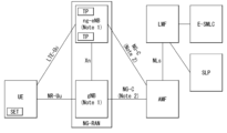
- FIG. 8 is a diagram illustrating an example of an architecture of a system for measuring a location of a terminal.
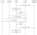
- FIG. 9 is a diagram illustrating an example of a procedure for measuring a location of a terminal.
- 10 is a diagram illustrating an example of a protocol layer for supporting LPP message transmission.
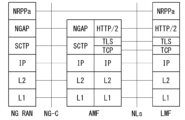
- 11 is a diagram illustrating an example of a protocol layer for supporting NRPPa transmission.
- FIG. 12 is a diagram illustrating an example of an OTDOA positioning method.
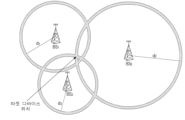
- FIGS. 13A and 13B are diagrams illustrating an example of a Multi RTT positioning method.
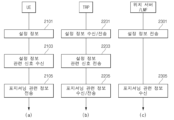
- FIG. 14 is a diagram briefly illustrating an operating method of a terminal, a TRP, a location server, and/or an LMF according to various embodiments of the present disclosure.
- 15 is a diagram briefly illustrating an operating method of a terminal, a TRP, a location server, and/or an LMF according to various embodiments of the present disclosure.
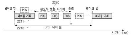
- 16 is a diagram illustrating an example of a PRS transmission/reception operation in an RRC inactive/idle state.
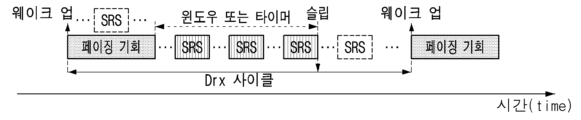
- 17 is a diagram illustrating an example of an SRS transmission/reception operation in an RRC inactive/idle state.
- FIG. 18 is a diagram illustrating an example in which a UE in an RRC inactive state transmits an SRS.
- 19 is a diagram illustrating an example in which a UE in an RRC inactive state receives a PRS.
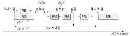
- 20 is a diagram illustrating an example in which a terminal in an inactive state receives a PRS.
- 21 is a diagram illustrating an example in which a terminal in an inactive state receives a PRS based on a time window.
- 22 and 23 are diagrams illustrating an example in which a terminal in an inactive state receives a PRS based on a time window.
- 24 is a diagram illustrating an example in which a terminal in an inactive state receives a PRS based on a time window.
- 25 is a diagram illustrating an example in which a terminal in an inactive state receives a PRS based on a time window.
- 26 and 27 are diagrams illustrating an example in which a terminal in an inactive state receives a PRS based on a time window.
- FIG. 28 is a diagram illustrating an example in which a method proposed in this specification is performed in a terminal.
- 29 is a diagram illustrating an example in which a method proposed in this specification is performed in a base station.
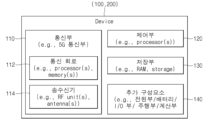
- 31 illustrates a wireless device applicable to this specification.
- downlink means communication from a base station to a terminal
- uplink means communication from a terminal to a base station.
- a transmitter may be part of a base station and a receiver may be part of a terminal.
- a transmitter may be a part of a terminal and a receiver may be a part of a base station.
- a base station may be expressed as a first communication device
- a terminal may be expressed as a second communication device.
- a base station includes a fixed station, a Node B, an evolved-NodeB (eNB), a Next Generation NodeB (gNB), a base transceiver system (BTS), an access point (AP), and a network (5G network), AI system, RSU (road side unit), vehicle, robot, drone (Unmanned Aerial Vehicle, UAV), AR (Augmented Reality) device, VR (Virtual Reality) device, etc. there is.
- a terminal may be fixed or mobile, and a user equipment (UE), a mobile station (MS), a user terminal (UT), a mobile subscriber station (MSS), a subscriber station (SS), and an advanced mobile (AMS) Station), WT (Wireless terminal), MTC (Machine-Type Communication) device, M2M (Machine-to-Machine) device, D2D (Device-to-Device) device, vehicle, robot, AI module , drone (Unmanned Aerial Vehicle, UAV), AR (Augmented Reality) device, VR (Virtual Reality) device, etc.
- UE user equipment
- MS mobile station
- UT user terminal
- MSS mobile subscriber station
- SS subscriber station
- AMS advanced mobile
- WT Wireless terminal
- MTC Machine-Type Communication
- M2M Machine-to-Machine
- D2D Device-to-Device
- vehicle robot
- AI module AI module
- drone Unmanned Aerial Vehicle, UAV
- AR
- CDMA may be implemented with a radio technology such as Universal Terrestrial Radio Access (UTRA) or CDMA2000.
- TDMA may be implemented with a radio technology such as Global System for Mobile communications (GSM)/General Packet Radio Service (GPRS)/Enhanced Data Rates for GSM Evolution (EDGE).
- GSM Global System for Mobile communications
- GPRS General Packet Radio Service
- EDGE Enhanced Data Rates for GSM Evolution
- OFDMA may be implemented with radio technologies such as IEEE 802.11 (Wi-Fi), IEEE 802.16 (WiMAX), IEEE 802-20, and Evolved UTRA (E-UTRA).
- UTRA is part of the Universal Mobile Telecommunications System (UMTS).
- 3rd Generation Partnership Project (3GPP) Long Term Evolution (LTE) is a part of Evolved UMTS (E-UMTS) using E-UTRA
- LTE-A (Advanced) / LTE-A pro is an evolved version of 3GPP LTE.
- 3GPP NR New Radio or New Radio Access Technology
- 3GPP LTE/LTE-A/LTE-A pro is an evolved version of 3GPP LTE/LTE-A/LTE-A pro.
- LTE refers to technology after 3GPP TS 36.xxx Release 8.
- LTE technology after 3GPP TS 36.xxx Release 10 is referred to as LTE-A
- LTE technology after 3GPP TS 36.xxx Release 13 is referred to as LTE-A pro
- 3GPP NR refers to technology after TS 38.xxx Release 15.
- LTE/NR may be referred to as a 3GPP system.
- "xxx" means standard document detail number.
- LTE/NR may be collectively referred to as a 3GPP system.
- RRC Radio Resource Control
- RRC Radio Resource Control
- NR is an expression representing an example of 5G radio access technology (RAT).
- RAT 5G radio access technology
- a new RAT system including NR uses an OFDM transmission scheme or a transmission scheme similar thereto.
- the new RAT system may follow OFDM parameters different from those of LTE.
- the new RAT system may follow the numerology of the existing LTE/LTE-A as it is, but may have a larger system bandwidth (eg, 100 MHz).
- one cell may support a plurality of numerologies. That is, terminals operating with different numerologies can coexist in one cell.
- a numerology corresponds to one subcarrier spacing in the frequency domain. By scaling the reference subcarrier spacing to an integer N, different numerologies can be defined.
- eLTE eNB is an evolution of eNB that supports connectivity to EPC and NGC.
- gNB A node that supports NR as well as connectivity with NGC.
- New RAN A radio access network that supports NR or E-UTRA or interacts with NGC.
- Network slice is a network defined by an operator to provide an optimized solution for a specific market scenario that requires specific requirements along with end-to-end coverage.
- Network function is a logical node within a network infrastructure that has a well-defined external interface and well-defined functional behavior.
- NG-C Control plane interface used for NG2 reference point between new RAN and NGC.
- NG-U User plane interface used for NG3 reference point between new RAN and NGC.
- Non-standalone NR A deployment configuration in which a gNB requires an LTE eNB as an anchor for control plane connection to EPC or an eLTE eNB as an anchor for control plane connection to NGC.
- Non-Standalone E-UTRA A deployment configuration in which the eLTE eNB requires the gNB as an anchor for control plane connectivity to the NGC.
- User Plane Gateway The endpoint of the NG-U interface.
- FIG. 1 shows an example of the overall system structure of NR to which the method proposed in this specification can be applied.
- NG-RAN consists of NG-RA user plane (new AS sublayer / PDCP / RLC / MAC / PHY) and gNBs that provide control plane (RRC) protocol termination for User Equipment (UE).
- RRC control plane
- the gNBs are interconnected through an Xn interface.
- the gNB is also connected to the NGC through an NG interface.
- the gNB is connected to an Access and Mobility Management Function (AMF) through an N2 interface and to a User Plane Function (UPF) through an N3 interface.
- AMF Access and Mobility Management Function
- UPF User Plane Function
- the numerology may be defined by subcarrier spacing and CP (Cyclic Prefix) overhead.
- the number of subcarrier intervals is the basic subcarrier interval as an integer N (or, ), which can be derived by scaling.
- N or, the numerology used can be selected independently of the frequency band.
- various frame structures according to a plurality of numerologies may be supported.
- OFDM orthogonal frequency division multiplexing
- a number of OFDM numerologies supported in the NR system can be defined as shown in Table 1.
- NR supports multiple numerologies (or subcarrier spacing (SCS)) to support various 5G services. For example, when the SCS is 15 kHz, it supports a wide area in traditional cellular bands, and when the SCS is 30 kHz/60 kHz, dense-urban, lower latency and a wider carrier bandwidth, and when the SCS is 60 kHz or higher, a bandwidth greater than 24.25 GHz is supported to overcome phase noise.
- SCS subcarrier spacing
- the NR frequency band is defined as a frequency range of two types (FR1 and FR2).
- FR1 and FR2 may be configured as shown in Table 2 below.
- FR2 may mean millimeter wave (mmW).
- Downlink and uplink transmission It consists of a radio frame having a section of.
- each radio frame is It consists of 10 subframes having a section of .
- FIG. 2 shows a relationship between an uplink frame and a downlink frame in a wireless communication system to which the method proposed in this specification can be applied.
- the transmission of uplink frame number i from a user equipment (UE) is greater than the start of the corresponding downlink frame in the corresponding terminal. You have to start earlier.
- the slots are in the subframe are numbered in increasing order of, and within a radio frame are numbered in increasing order of one slot is It consists of consecutive OFDM symbols of is determined according to the used numerology and slot configuration.
- slot in subframe The start of is an OFDM symbol in the same subframe chronologically aligned with the beginning of
- Not all terminals can simultaneously transmit and receive, which means that not all OFDM symbols in a downlink slot or uplink slot can be used.
- Table 3 shows the number of OFDM symbols per slot in a normal CP ( ), the number of slots per radio frame ( ), the number of slots per subframe ( ), and Table 3 shows the number of OFDM symbols per slot, the number of slots per radio frame, and the number of slots per subframe in an extended CP.
- FIG. 3 shows an example of a frame structure in the NR system.
- Figure 3 is only for convenience of description and does not limit the scope of the present invention.
- a mini-slot may consist of 2, 4 or 7 symbols, or may consist of more or fewer symbols.
- an antenna port a resource grid, a resource element, a resource block, a carrier part, etc. can be considered
- the antenna port is defined such that the channel on which a symbol on the antenna port is carried can be inferred from the channel on which other symbols on the same antenna port are carried. If the large-scale properties of the channel on which the symbols on one antenna port are carried can be inferred from the channel on which the symbols on the other antenna port are carried, then the two antenna ports are quasi co-located or QC/QCL (quasi co-located or quasi co-location).
- the wide range characteristic includes one or more of delay spread, Doppler spread, frequency shift, average received power, and received timing.
- FIG. 4 shows an example of a resource grid supported by a wireless communication system to which the method proposed in this specification can be applied.
- the resource grid on the frequency domain It is composed of subcarriers, and one subframe It is described as being composed of OFDM symbols as an example, but is not limited thereto.
- the transmitted signal is one or more resource grids composed of subcarriers and It is described by the OFDM symbols of From here, am. remind represents the maximum transmission bandwidth, which may vary between uplink and downlink as well as numerologies.
- numerology And one resource grid may be set for each antenna port p.
- 5 shows examples of resource grids for each antenna port and numerology to which the method proposed in this specification can be applied.
- each element of the resource grid for antenna port p is referred to as a resource element, and an index pair uniquely identified by From here, is an index in the frequency domain, denotes the position of a symbol within a subframe.
- an index pair this is used From here, am.
- the resource element for antenna port p is a complex value corresponds to If there is no risk of confusion or if a specific antenna port or numerology is not specified, the indices p and may be dropped, so that the complex value is or This can be.
- the physical resource block (physical resource block) is in the frequency domain defined as contiguous subcarriers.
- Point A serves as a common reference point of the resource block grid and can be obtained as follows.
- -offsetToPointA for PCell downlink indicates the frequency offset between point A and the lowest subcarrier of the lowest resource block overlapping the SS / PBCH block used by the UE for initial cell selection, and for FR1 15 kHz subcarrier spacing and It is expressed in resource block units assuming a 60 kHz subcarrier spacing for FR2;
- -absoluteFrequencyPointA represents the frequency-position of point A expressed as in ARFCN (absolute radio-frequency channel number).
- Common resource blocks set subcarrier spacing It is numbered upward from 0 in the frequency domain for .
- Is It can be defined relative to point A to correspond to a subcarrier centered on this point A.
- Physical resource blocks are numbered from 0 within the bandwidth part (BWP). are numbered up to, is the number of BWP.
- Physical resource block in BWP i and common resource block The relationship between can be given by Equation 2 below.
- a terminal receives information from a base station through downlink (DL), and the terminal transmits information to the base station through uplink (UL).
- Information transmitted and received between the base station and the terminal includes data and various control information, and various physical channels exist according to the type/use of the information transmitted and received by the base station and the terminal.
- the terminal When the terminal is turned on or newly enters a cell, the terminal performs an initial cell search operation such as synchronizing with the base station (S601). To this end, the terminal may receive a primary synchronization signal (PSS) and a secondary synchronization signal (SSS) from the base station to synchronize with the base station and obtain information such as a cell ID. After that, the terminal can acquire intra-cell broadcast information by receiving a physical broadcast channel (PBCH) from the base station. Meanwhile, the terminal may check the downlink channel state by receiving a downlink reference signal (DL RS) in the initial cell search step.
- PSS primary synchronization signal
- SSS secondary synchronization signal
- PBCH physical broadcast channel
- DL RS downlink reference signal
- the UE After completing the initial cell search, the UE acquires more detailed system information by receiving a Physical Downlink Control Channel (PDCCH) and a Physical Downlink Shared Channel (PDSCH) according to the information carried on the PDCCH. It can (S602).
- PDCCH Physical Downlink Control Channel
- PDSCH Physical Downlink Shared Channel
- the terminal may perform a random access procedure (RACH) for the base station (S603 to S606).
- RACH random access procedure
- the UE transmits a specific sequence as a preamble through a physical random access channel (PRACH) (S603 and S605), and responds to the preamble through a PDCCH and a corresponding PDSCH (RAR (Random Access Channel) Response) message) may be received
- PRACH physical random access channel
- RAR Random Access Channel
- a contention resolution procedure may be additionally performed (S606).
- the UE receives PDCCH/PDSCH as a general uplink/downlink signal transmission procedure (S607) and physical uplink shared channel (PUSCH)/physical uplink control channel (PUSCH). Control Channel; PUCCH) transmission (S608) may be performed.
- the terminal may receive downlink control information (DCI) through the PDCCH.
- DCI downlink control information
- the DCI includes control information such as resource allocation information for the terminal, and different formats may be applied depending on the purpose of use.
- control information that the terminal transmits to the base station through the uplink or the terminal receives from the base station is a downlink / uplink ACK / NACK signal, CQI (Channel Quality Indicator), PMI (Precoding Matrix Index), RI (Rank Indicator) ) and the like.
- the UE may transmit control information such as the aforementioned CQI/PMI/RI through PUSCH and/or PUCCH.
- the BM procedure sets a set of base station (eg, gNB, TRP, etc.) and / or terminal (eg, UE) beams that can be used for downlink (DL) and uplink (UL) transmission / reception
- DL downlink
- UL uplink
- L1 layer 1
- L2 layer 2
- - Beam measurement An operation in which a base station or UE measures characteristics of a received beamforming signal.
- - Beam determination An operation in which a base station or UE selects its own Tx beam / Rx beam.
- - Beam sweeping An operation of covering a spatial area by using a transmission and/or reception beam for a predetermined time interval in a predetermined manner.
- - Beam report An operation in which the UE reports information on a beamformed signal based on beam measurement.
- the BM procedure can be divided into (1) a DL BM procedure using a synchronization signal (SS)/physical broadcast channel (PBCH) block or CSI-RS, and (2) a UL BM procedure using a sounding reference signal (SRS).
- each BM procedure may include Tx beam sweeping to determine the Tx beam and Rx beam sweeping to determine the Rx beam.
- DL BM Procedure Downlink beam management procedure
- the downlink beam management procedure includes (1) the base station transmitting a beamforming DL RS (eg, CSI-RS or SS block (SSB)) and (2) the terminal transmitting a beam report steps may be included.
- a beamforming DL RS eg, CSI-RS or SS block (SSB)
- SSB SS block
- beam reporting may include preferred DL RS ID (identifier) (s) and corresponding L1-RSRP.
- the DL RS ID may be SSB resource indicator (SSBRI) or CSI-RS resource indicator (CRI).
- SSBRI SSB resource indicator
- CRI CSI-RS resource indicator
- a base station described in this specification may mean a generic term for an object that transmits and receives data with a terminal.
- a base station described herein may be a concept including one or more transmission points (TPs), one or more transmission and reception points (TRPs), and the like.
- TPs transmission points
- TRPs transmission and reception points
- multiple TPs and/or multiple TRPs described herein may be included in one base station or included in multiple base stations.
- the TP and/or the TRP may include a panel of a base station, a transmission and reception unit, and the like.
- the TRP described herein may mean an antenna array having one or more antenna elements available in a network located at a specific geographic location in a specific area.
- TRP is a base station, a transmission point (TP), a cell (eg, macro cell / small cell / pico cell, etc.), an antenna array, or a panel (panel), etc., and can be understood/applied.
- BSSID Basic Service Set Identifier
- CID Cell-ID (positioning method)
- E-SMLC Enhanced Serving Mobile Location Center
- E-CID Enhanced Cell-ID (positioning method)
- EGNOS European Geostationary Navigation Overlay Service
- E-UTRAN Evolved Universal Terrestrial Radio Access Network
- GAGAN GPS Aided Geo Augmented Navigation
- GLONASS GLObal'naya NAvigatsionnaya Sputnikovayassela (Engl.: Global Navigation Satellite System)
- GMLC Gateway Mobile Location Center
- GNSS Global Navigation Satellite System
- GPS Global Positioning System
- HESSID Homogeneous Extended Service Set Identifier
- MBS Metropolitan Beacon System
- MO-LR Mobile Originated Location Request
- MT-LR Mobile Terminated Location Request
- NG-C NG control plane
- NG-AP NG Application Protocol
- NI-LR Network Induced Location Request
- NRPPa NR Positioning Protocol A
- QZSS Quasi-Zenith Satellite System
- RSTD Reference Signal Time Difference / Relative Signal Time Difference
- TBS Terrestrial Beacon System
- TRP Transmission and Reception Point
- UE User Equipment
- WLAN Wireless Local Area Network
- Positioning may mean determining a geographic location and/or speed of a UE by measuring a radio signal.
- Location information may be requested by a client (eg, application) associated with the UE and reported to the client.
- the location information may be included in a core network or may be requested by a client connected to the core network.
- the location information may be reported in a standard format such as cell-based or geographic coordinates, and in this case, an estimation error value for the location and speed of the UE and/or a positioning method used for positioning can report together.
- FIG. 7 is a diagram illustrating an example of a positioning protocol configuration for measuring a location of a terminal.
- the LPP is a location server (E) to locate a target device (UE and/or SET) using position-related measurements obtained from one or more reference sources.
- a target device UE and/or SET
- -SMLC and / or SLP and / or LMF position-related measurements obtained from one or more reference sources.
- the target device and location server can exchange measurement and/or location information based on signal A and/or signal B.
- NRPPa may be used for information exchange between a reference source (ACCESS NODE and/or BS and/or TP and/or NG-RAN node) and a location server.
- a reference source ACCESS NODE and/or BS and/or TP and/or NG-RAN node
- Functions provided by the NRPPa protocol may include the following.
- PRS Positioning Reference Signal
- PRS is a reference signal used for location estimation of a UE.
- PRS mapping may be performed based on Table 6 below.
- the PRS reception procedure of the terminal may be performed based on Table 7 below.
- FIG. 8 is a diagram illustrating an example of an architecture of a system for measuring a location of a terminal.
- AMF Core Access and Mobility Management Function receives a request for a location service related to a specific target UE from another entity such as a Gateway Mobile Location Center (GMLC), or AMF itself receives a request for a location service related to a specific target UE. It may decide to start location services on behalf of the UE. Then, the AMF transmits a location service request to a Location Management Function (LMF).
- LMF Location Management Function
- the LMF receiving the location service request may process the location service request and return a processing result including an estimated location of the UE to the AMF. Meanwhile, when the location service request is received from another entity such as GMLC in addition to the AMF, the AMF may transfer the processing result received from the LMF to the other entity.
- ng-eNB new generation evolved-NB
- gNB are network elements of NG-RAN that can provide measurement results for location tracking, and can measure radio signals for a target UE and deliver the result to the LMF.
- the ng-eNB may control several Transmission Points (TPs) such as remote radio heads or PRS-dedicated TPs supporting a PRS-based beacon system for E-UTRA.
- TPs Transmission Points
- the LMF is connected to an Enhanced Serving Mobile Location Center (E-SMLC), and the E-SMLC enables the LMF to access the E-UTRAN.
- E-SMLC uses OTDOA, which is one of the positioning methods of E-UTRAN, by using downlink measurements obtained by a target UE through a signal transmitted by an LMF from PRS-dedicated TPs in an eNB and/or E-UTRAN. (Observed Time Difference Of Arrival) can be supported.
- the LMF may be connected to a SUPL Location Platform (SLP).
- the LMF can support and manage different location services for target UEs.
- the LMF may interact with the serving ng-eNB or serving gNB for the target UE to obtain the location measurement of the UE.
- the LMF selects a positioning method based on a Location Service (LCS) client type, required Quality of Service (QoS), UE positioning capabilities, gNB positioning capabilities, and ng-eNB positioning capabilities. and may apply this positioning method to the serving gNB and/or the serving ng-eNB.
- the LMF can determine the location estimate for the target UE and additional information such as the accuracy of the location estimate and velocity.
- the SLP is a Secure User Plane Location (SUPL) entity responsible for positioning through a user plane.
- SUPL Secure User Plane Location
- the UE may measure the location of the UE by utilizing a downlink reference signal transmitted from the NG-RAN and the E-UTRAN.
- the downlink reference signal transmitted to the UE from the NG-RAN and the E-UTRAN may include an SS / PBCH block, CSI-RS and / or PRS, etc., and the location of the UE using any downlink reference signal Whether to measure may depend on settings such as LMF / E-SMLC / ng-eNB / E-UTRAN.
- the UE may include an LCS application, and may access the LCS application through communication with a network to which the UE is connected or another application included in the UE.
- the LCS application may include the measurement and calculation functions necessary to determine the location of the UE.
- the UE may include an independent positioning function such as Global Positioning System (GPS), and may report the location of the UE independently of NG-RAN transmission. Positioning information obtained independently may be used as auxiliary information of positioning information obtained from a network.
- GPS Global Positioning System
- FIG. 9 is a diagram illustrating an example of a procedure for measuring a location of a terminal.
- CM-IDLE Connection Management - IDLE
- the AMF When the UE is in CM-IDLE (Connection Management - IDLE) state, when the AMF receives a location service request, the AMF establishes a signaling connection with the UE and uses a network trigger service to allocate a specific serving gNB or ng-eNB. can request This operation process is omitted in FIG. 9 . That is, in FIG. 8 , it may be assumed that the UE is in a connected mode. However, the signaling connection may be released during the positioning process by the NG-RAN for reasons such as signaling and data inactivity.
- a 5GC entity such as GMLC may request a location service for measuring the location of a target UE from a serving AMF.
- the serving AMF may determine that the location service for measuring the location of the target UE is required. For example, in order to measure the location of a UE for an emergency call, the serving AMF may determine to directly perform location service.
- the AMF sends a location service request to the LMF, according to step 2, and according to step 3a, the LMF serves location procedures to obtain location measurement data or location assistance data.
- the LMF may request location-related information related to one or more UEs from the NG-RAN and indicate the type of location information and related QoS required.
- the NG-RAN may transmit location-related information to the LMF in response to the request.
- the location determination method according to the request is E-CID
- the NG-RAN may transmit additional location-related information to the LMF through one or more NRPPa messages.
- 'location-related information' may refer to all values used for location calculation, such as actual location estimation information and wireless measurement or location measurement.
- the protocol used in step 3a may be the NRPPa protocol, which will be described later.
- the LMF may initiate location procedures for downlink location with the UE.
- the LMF may transmit location assistance data to the UE or obtain a location estimate or location measurement.
- a capability transfer process may be performed.
- the LMF may request capability information from the UE, and the UE may transmit capability information to the LMF.
- capability information refers to various aspects (aspects) of a specific location measurement method, such as information on a location measurement method that can be supported by LFM or UE, and various types of assistance data for A-GNSS. ) and information on common features that are not limited to any one location measurement method, such as the ability to handle multiple LPP transactions.
- the UE may provide capability information to the LMF.
- a location assistance data transfer process may be performed in step 3b.
- the UE may request location assistance data from the LMF, and may indicate required specific location assistance data to the LMF.
- the LMF may deliver location assistance data corresponding thereto to the UE, and may additionally transmit additional assistance data to the UE through one or more additional LPP messages.
- the location assistance data transmitted from the LMF to the UE may be transmitted through a unicast method, and in some cases, the LMF sends the location assistance data and/or Alternatively, additional auxiliary data may be transmitted to the UE.
- a location information transfer process may be performed in step 3b.
- the LMF may request location-related information related to the corresponding UE from the UE, and may indicate the type of required location information and related QoS. Then, the UE may transmit location-related information to the LMF in response to the request. At this time, the UE may additionally transmit additional location-related information to the LMF through one or more LPP messages.
- 'location-related information' may refer to all values used for position calculation, such as actual position estimation information and radio measurement or position measurement, and representatively, UE from a plurality of NG-RANs and/or E-UTRANs.
- RSTD Reference Signal Time Difference
- step 3b is performed in the order of a capability transfer process, an assistance data transfer process, and a location information transfer process, but is not limited to this order.
- step 3b is not restricted in any particular order to improve the flexibility of positioning.
- the UE may request location assistance data at any time to perform a location measurement request that the LMF has already requested.
- the LMF may request location information such as a location measurement value or a location estimation value at any time.
- the UE may transmit capability information to the LMF at any time.
- an error message may be transmitted and received, and an abort message to stop position measurement may be transmitted and received.
- the protocol used in step 3b may be an LPP protocol, which will be described later.
- step 3b may be additionally performed after step 3a is performed, but may be performed instead of step 3a.
- the LMF may provide a location service response to the AMF.
- the location service response may include information on whether the location estimation of the UE was successful and a location estimate of the UE. Then, if the procedure of FIG. 9 is initiated by step 1a, the AMF may deliver a location service response to a 5GC entity such as GMLC, and if the procedure of FIG. For service provision, a location service response may be used.
- LTP LTE Positioning Protocol
- 10 is a diagram illustrating an example of a protocol layer for supporting LPP message transmission.
- LPP PDUs may be transmitted through NAS PDUs between MAFs and UEs.
- LPP is a terminated connection between a target device (e.g. UE in the control plane or SUPL Enabled Terminal (SET) in the user plane) and a location server (e.g. LMF in the control plane or SLP in the user plane). )can do.
- the LPP message may be delivered in the form of a transparent PDU over an intermediate network interface using an appropriate protocol such as NGAP over the NG-C interface, NAS/RRC over the LTE-Uu and NR-Uu interfaces.
- the LPP protocol enables positioning for NR and LTE using multiple positioning methods.
- the target device and the location server may exchange capability information, auxiliary data for positioning, and/or location information through the LPP protocol.
- error information exchange and/or an LPP procedure interruption instruction may be performed through an LPP message.
- NRPPa NR Positioning Protocol A
- FIG. 11 is a diagram illustrating an example of a protocol layer for supporting NRPPa transmission. Specifically, FIG. 11 illustrates a protocol layer for supporting transmission of NRPPa PDU (NR Positioning Protocol a Protocol Data Unit).
- NRPPa PDU NR Positioning Protocol a Protocol Data Unit
- NRPPa can be used for information exchange between NG-RAN nodes and LMF. Specifically, NRPPa can exchange E-CID for measurement transmitted from ng-eNB to LMF, data to support OTDOA positioning method, Cell-ID and Cell location ID for NR Cell ID positioning method.
- the AMF may route NRPPa PDUs based on the routing ID of the associated LMF through the NG-C interface even if there is no information on the associated NRPPa transaction.
- the procedures of the NRPPa protocol for location and data collection can be divided into two types.
- the first type is a UE associated procedure for delivering information (eg, location measurement information, etc.) for a specific UE
- the second type is information applicable to NG-RAN nodes and related TPs ( For example, it is a non-UE associated procedure for delivering gNB/ng-eNG/TP timing information, etc.).
- the above two types of procedures may be supported independently or simultaneously.
- Positioning methods supported by NG-RAN include GNSS, OTDOA, E-CID (enhanced cell ID), Multi RTT (round trip time)/Multi-cell RTT, barometric sensor positioning, WLAN positioning, Bluetooth positioning, and TBS (terrestrial beacon system), Uplink Time Difference of Arrival (UTDOA), and the like.
- the position of the UE may be measured using any one of the above positioning methods, but the position of the UE may be measured using two or more positioning methods.
- FIG. 12 is a diagram illustrating an example of an OTDOA positioning method.
- the OTDOA positioning method uses measurement timing of downlink signals received by a UE from multiple TPs including an eNB, ng-eNB and a PRS dedicated TP.
- the UE uses the location assistance data received from the location server to measure the timing of the received downlink signals.
- the location of the UE may be determined based on the measurement result and the geographic coordinates of neighboring TPs.
- a UE connected to the gNB may request a measurement gap for OTDOA measurement from the TP. If the UE does not recognize the SFN for at least one TP in the OTDOA auxiliary data, the UE requests a measurement gap to perform a Reference Signal Time Difference (RSTD) measurement. Before requesting an OTDOA reference cell An autonomous gap can be used to obtain an SFN of
- the RSTD may be defined based on the smallest relative time difference between the boundaries of two subframes each received from the reference cell and the measurement cell. That is, it may be calculated based on a relative time difference between the start time of the subframe of the reference cell closest to the start time of the subframe received from the measurement cell. Meanwhile, a reference cell may be selected by the UE.
- TOA time of arrival
- RSTD time of arrival
- RSTD for two TPs can be calculated based on Equation 3 below.
- ⁇ xt, yt ⁇ are the (unknown) coordinates of the target UE
- ⁇ xi, yi ⁇ are the (known) coordinates of the TP
- ⁇ x1, y1 ⁇ is the reference TP (or other TP) may be coordinates.
- (Ti-T1) is a transmission time offset between two TPs, and may be named “Real Time Differences” (RTDs)
- ni and n1 may represent values related to UE TOA measurement errors.
- E-CID Enhanced Cell ID
- the location of the UE may be measured through geographic information of the serving ng-eNB, serving gNB and/or serving cell of the UE.
- geographic information of the serving ng-eNB, the serving gNB, and/or the serving cell may be obtained through paging, registration, and the like.
- the E-CID positioning method may use additional UE measurement and/or NG-RAN radio resources for improving the UE position estimation value in addition to the CID positioning method.
- some of the same measurement methods as the measurement control system of the RRC protocol may be used, but in general, additional measurement is not performed only for the location measurement of the UE.
- a separate measurement configuration or measurement control message may not be provided to measure the location of the UE, and the UE does not expect an additional measurement operation only for location measurement to be requested.
- the UE may report measurement values obtained through generally measurable measurement methods.
- the serving gNB may implement the E-CID location method using E-UTRA measurements provided from the UE.
- measurement elements that can be used for E-CID positioning may be as follows.
- E-UTRA RSRP Reference Signal Received Power
- E-UTRA RSRQ Reference Signal Received Quality
- UE E-UTRA reception-transmission time difference Rx-Tx Time difference
- GERAN/WLAN RSSI Reference Signal Strength Indication
- UTRAN CPICH Common Pilot Channel
- RSCP Receiveived Signal Code Power
- ng-eNB reception-transmission time difference Rx-Tx Time difference
- TADV timing advance
- AoA Angle of Arrival
- TADV can be divided into Type 1 and Type 2 as follows.
- TADV Type 1 (ng-eNB reception-transmission time difference) + (UE E-UTRA reception-transmission time difference)
- TADV Type 2 ng-eNB receive-transmit time difference
- AoA may be used to measure the direction of the UE.
- AoA may be defined as the estimated angle of the UE's position in a counterclockwise direction from the base station/TP. In this case, the geographical reference direction may be north.
- the base station/TP may use an uplink signal such as a sounding reference signal (SRS) and/or a demodulation reference signal (DMRS) for AoA measurement.
- SRS sounding reference signal
- DMRS demodulation reference signal
- the larger the array of antenna arrays the higher the accuracy of AoA measurement.
- signals received from adjacent antenna elements may have a constant phase-rotation.
- UTDOA is a method of determining the location of a UE by estimating the arrival time of the SRS.
- the location of the UE can be estimated through an arrival time difference with another cell (or base station/TP) by using the serving cell as a reference cell.
- the E-SMLC may indicate a serving cell of the target UE in order to instruct the target UE to transmit SRS.
- E-SMLC can provide configuration such as periodic/aperiodic SRS, bandwidth and frequency/group/sequence hopping.
- Multi-RTT Multi-cell RTT
- RTT is based on TOA measurement, but approximates TRP (eg, coarse TRP).
- TRP eg, coarse TRP
- base station only requires timing synchronization.
- 13a and 13b are diagrams illustrating an example of a multi RTT positioning method.
- the initiating device may be a TRP and/or a terminal
- the responding device may be a terminal and/or a TRP.
- the initiating device transmits the RTT measurement request, and the responding device may receive it.
- the initiating device may transmit the RTT measurement signal at t0, and the responding device may obtain the TOA measurement t1.
- the responding device may transmit the RTT measurement signal at t2, and the initiating device may obtain the TOA measurement t3.
- the responding device may transmit information on [t2-t1], and the initiating device may receive the corresponding information and calculate RTT based on Equation 4 below.
- Corresponding information may be transmitted/received based on a separate signal or included in the RTT measurement signal of B805 and transmitted/received.
- the corresponding RTT may correspond to double-range measurement between two devices. Positioning estimation may be performed from corresponding information, and a multilateration technique may be used. Based on the measured RTT, d1, d2, and d3 can be determined, and the target device location can be determined as the intersection point of the circumference with each BS1, BS2, and BS3 (or TRP) as the center and each d1, d2, and d3 as the radius. there is.
- a sounding procedure for positioning a UE in an NR system to which various embodiments of the present disclosure are applicable may be based on Table 13 below.
- the sounding procedure may be triggered by the SRS request field included in DCI format 0_1.
- DCI format 0_1 A more specific DCI format setting may be based on Table 14 below.
- PRS mapping may be based on Table 15 below.
- paging may be based on Table 16 below.
- FIG. 14 is a diagram briefly illustrating an operating method of a terminal, a TRP, a location server, and/or an LMF according to various embodiments of the present disclosure.
- the location server and/or the LMF may transmit configuration information to the terminal, and the terminal may receive it.
- the location server and/or the LMF may transmit reference setting information to a transmission and reception point (TRP), and the TRP may receive it.
- TRP transmission and reception point
- the TRP may transmit reference setting information to the terminal, and the terminal may receive it.
- operation 2001 according to an exemplary embodiment may be omitted.
- operations 2003 and 2005 according to an exemplary embodiment may be omitted.
- operation 2001 according to an exemplary embodiment may be performed.
- operation 2001 according to the exemplary embodiment and operations 2003 and 2005 according to the exemplary embodiment may be optional.
- the TRP may transmit a signal related to configuration information to the terminal, and the terminal may receive it.
- a signal related to configuration information may be a signal for positioning of a terminal.
- the terminal may transmit a signal related to positioning to the TRP, and the TRP may receive it.
- the TRP may transmit a signal related to positioning to the location server and/or LMF, and the location server and/or LMF may receive it.
- the terminal may transmit a signal related to positioning to the location server and/or LMF, and the location server and/or LMF may receive it.
- operations 2009 and 2011 according to an exemplary embodiment may be omitted.
- operation 2013 according to an exemplary embodiment may be omitted.
- operations 2011 and 2013 according to an exemplary embodiment may be performed.
- operations 2009 and 2011 according to the exemplary embodiment and operation 2013 according to the exemplary embodiment may be optional.
- the signal related to positioning may be obtained based on setting information and/or a signal related to setting information.
- 15 is a diagram briefly illustrating an operating method of a terminal, a TRP, a location server, and/or an LMF according to various embodiments of the present disclosure.
- a terminal may receive configuration information.
- the terminal may receive a signal related to configuration information.
- the terminal may transmit positioning-related information.
- the TRP may receive configuration information from the location server and/or LMF, and may transmit it to the terminal.
- the TRP may transmit a signal related to configuration information.
- the TRP may receive location-related information and may transmit it to the location server and/or LMF.
- the location server and/or the LMF may transmit configuration information.
- the location server and/or LMF may receive information related to location.
- the above-described setting information in the following description of various embodiments of the present disclosure, reference configuration (information), reference setting (information), reference setting (information), location server and / or LMF and / or It is understood that the TRP is related to one or more information transmitted / configured to the terminal, and / or the corresponding reference configuration (information), reference setting (information), reference setting (information), location server and / or LMF and / or TRP is the terminal It can be understood as one or more pieces of information transmitted/set to .
- the above-described signal related to positioning is understood as a signal related to one or more of information reported by a terminal in the following description of various embodiments of the present disclosure, and/or one of information reported by the terminal. It can be understood as a signal containing an abnormality.
- a base station, a gNB, a cell, etc. may be replaced with a TRP, a TP, or any device having the same role.
- the location server may be replaced by an LMF or an arbitrary device having the same role.
- the terminal transitions to a sleep mode or transitions from an RRC connected state to an inactive or idle state.
- positioning/positioning measurement may be performed in a connected state. If positioning/positioning measurement is supported to increase the accuracy of location measurement for a terminal in various use cases and RRC inactive/idle state, the terminal is in a sleep mode ), it is necessary to consider the duration of the transition (ie, DRX cycle), and at this time, a rule for operation in the terminal and the base station / server is required.
- the terminal transitions to a sleep mode for a certain period of time to prevent indiscriminate power consumption, and then wakes up before the active time to perform PDCCH monitoring (monitoring) The operation of expecting and monitoring the reception of paging is repeated.
- PDCCH monitoring monitoring
- the basic operation related to channel measurement of the UE is performed at a measurement occasion that exists within the DRX active time.
- the DRX activation time active time means the time when the terminal side wakes up, not sleep mode, with the RF chain turned on.
- the mentioned server means a location server that manages the location of the terminal.
- the Physical Downlink Share Channel (PDSCH) required for transmission of the paging message described in this specification uses RRC and cannot be transmitted through MAC-CE, but positioning/positioning MAC-CE can be used for the purpose of
- Scenario #1 DL positioning measurement in RRC connected/inactive state
- a UE in an idle/inactive state receives a DRX cycle configuration through system information or RRC signaling, but the instructed DRX cycle It is usually longer than the period of PRS. That is, a terminal in an idle/inactive state receives configuration information for a DRX cycle through system information or RRC signaling, and sets the DRX cycle based on the configuration information. ) may be generally set longer than a period in which a UE receives a PRS/a period in which a base station transmits a PRS/a period in which a PRS resource is configured.
- the PRS cycle starts with at least 4 slots, and the DRX cycle is generally a radio frame unit [e.g. When transmitted as system information, 32, 64, 128, 256 radio frames], so multiple PRS transmissions / receptions can be performed between paging occasions (POs). That is, the PRS cycle can be set from a minimum of 4 slots, and the DRX cycle can generally be set in units of radio frames. PRS transmission of the base station / PRS reception of the terminal / PRS resource configuration may be performed between paging occasions (POs).
- POs paging occasions
- the base station/server needs to instruct/configure the terminal to measure only specific PRSs and to make state transition to the sleep mode again. That is, the base station/server instructs the UE, which has transitioned to the wake-up state within the DRX cycle, to perform measurement of only some specific PRSs among all PRSs set within the DRX cycle, and then transition to the sleep mode again. It needs to be configured to set. According to this method, the transmission burden on the side of the base station can be reduced. Here, if there is a gap between PRSs within a corresponding window or timer, the terminal can transition to micro/light sleep mode.
- the terminal after performing only measurements for a specific PRS among the entire PRS set within the DRX cycle within the DRX cycle, the terminal is only measured for a certain PRS, and then Windows/interval so that the state can be transparent in the slip mode again.
- a time interval or timer may be set. When a time gap exists between some specific PRSs that exist within the set window/interval/time interval or timer, the terminal selects a time interval between the specific PRSs.
- a state transition may be made to a micro/light sleep mode at a time gap.
- a base station or a server instructs a terminal about a window or a timer or continuous PRS resource (s) / set (resource (s) / set) to be measured by the terminal, and the instruction is set Until the PRS existing in the resource, the UE maintains a wake-up state, measures the PRS, and proposes a method for state transition to a sleep mode.
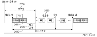
- FIG. 16 is a diagram illustrating an example of a PRS transmission/reception operation in an RRC inactive/idle state.
- the base station or the server sets a window for the UE to measure only some of the specific PRSs among all PRSs set in the DRX cycle 1610, a timer, or a continuous sequence to be measured by the UE.
- PRS resource (s) / set (resource (s) / set) may be set to the terminal (1620).
- the terminal transitions to a wake-up state, and exists after the paging opportunity 1611, and the set window, timer, or continuous PRS resource(s) to be measured by the terminal After performing measurement on PRS resource(s) 1621, 1623 and 1625 included in/existing in/in resource(s)/set 1621, 1623 and 1625, the state transitions to sleep mode can do.
- the window and timer use N bits to form 2 ⁇ N symbols or 2 ⁇ N slots or 2 ⁇ N subframes or 2 ⁇ N ms length/ It can be set in the form and can be directly indicated, such as N symbols, N slots, N subframes, N ms.
- the adjacent PRS resource(s) from the time of receiving the information or the end of the PO Alternatively, monitoring is performed for a set number of repetitions (repetition factor) for sets.
- an index for identifying the resource(s) or set and the number of times the resource(s) or set are repeatedly set/existent Information on the number of repetitions for is set, and the number of PRS resource(s) corresponding to the number of repetitions set for the neighboring PRS resource(s) or set from the time when the terminal receives the information or the PO is terminated, or You can monitor the set.
- monitoring is performed for a set number of repetition factors for PRS resource(s) or sets that are closest to the offset. That is, when offset information for the starting point of the window or timer is set to the UE, the UE is the PRS resource (s) that exists at the closest point in time from the point determined based on the offset (first existing). ) or sets, it is possible to perform monitoring for the number of PRS resource (s) or sets corresponding to the set number of repetitions.
- Method 1 Transmission through RRC signaling in system information or RRC connected state
- a window, a timer, or a continuous PRS resource (s) / It relates to a method of transmitting information about a set (resource(s)/set) through (i) system information or (ii) RRC signaling in an RRC connected state of a terminal.
- the method broadcasts information on the corresponding section through system information, or the RRC connection state before state transition to the RRC inactive / idle state ( This is a method of transmitting to the terminal through RRC signaling when in the connected state. That is, according to the present method, a window configured for the UE to measure only some specific PRSs among all PRSs configured in one DRX cycle, a timer, or continuous PRS resources to be measured by the UE Information on (s)/set (resource(s)/set) is broadcast through system information, or the RRC connected state, which is the state before the state transition of the terminal to the RRC inactive/idle state ), information on the window, timer, or continuous PRS resource (s) / set (resource (s) / set) to be measured by the terminal may be transmitted through RRC signaling.
- system information (SI) may be paging SI or positioning/positioning SI.
- the PRS resource ( s)/set When the terminal has the corresponding information and receives a request for activation (triggering) in the RRC inactive/idle state, the PRS resource ( s)/set to measure the PRS. That is, the terminal retains/stores information about the previously received window, timer or continuous PRS resource(s)/set to be measured by the terminal, and performs positioning.
- PRS When a request for measurement for RRC is received in the inactive/idle state, PRS is measured for PRS resource(s)/set existing within the window and timer interval, PRS may be measured for consecutive PRS resource(s)/set (resource(s)/set) configured based on the above information.
- the activation method is one on through Paging PDCCH (DCI) or Paging PDSCH (MAC-CE) or PEI (Paging Early Indication) discussed in NR PS (positioning system). It can be transmitted through the /off bit.
- the terminal can expect reception after every PO with a window or timer or resource (s)/set delivered through system information or RRC signaling without activation (triggering) information as default. That is, a window configured for the UE to measure only some specific PRSs among all PRSs configured in one DRX cycle, a timer, or a continuous PRS resource(s)/set to be measured by the UE.
- the terminal receiving the information on (resource(s)/set), without separate activation (triggering) information requesting measurement performance, as a defalut operation after every PO included in each DRX cycle, sets the window (window) , PRS reception in a timer or measurement for continuous PRS resource (s) / set (resource (s) / set) to be measured by the UE may be performed.
- signaling overhead can be reduced. That is, since signaling for activating/triggering measurement to the UE does not have to be performed separately, signaling overhead is reduced.
- the base station or server can deliver information about deactivation through methods 2 to 4 below. That is, the information on deactivation may be information for deactivating a default operation of a terminal expecting PRS reception after every PO.
- the information on the deactivation can be simply on-off 1-bit information, or it can be configured and transmitted as Mbitsized information to instruct deactivation to be performed after a predetermined number of POs.
- the method for transmitting the information is as follows. Methods 2-4 can be followed.
- This method is a method that can be used when group specific instruction is given.
- a reserved state of a short message indicator may be used or may be transmitted using reserved bit(s) within a short message or reserved bits outside the short message. That is, in order to transfer information for disabling the default operation of a terminal expecting PRS reception after every PO, the reserved state of a short message indicator, reserved bit(s) in a short message, or Reserved bits outside of short messages may be used.
- corresponding information information for disabling the default operation of a terminal expecting to receive a PRS after every PO
- the short message indicator corresponds to the existing short message
- Corresponding information may also play an activation role at the same time. If 'null' or 'zero', the terminal can consider it as non-activation. That is, when the short message indicator is set to 'null' or 'zero', the terminal may interpret it as non-activation.
- This method is a method that can be used when indicating for each UE through the PDSCH. According to the present method, a corresponding window or timer may be individually indicated in addition to the UE-ID in the paging message.
- the DCI bit field of the existing short message indicator includes only scheduling information ('01') or both a short message and PDSCH (scheduling information). ('11'). That is, when the PDSCH is used to transmit information for disabling the default operation of a terminal expecting PRS reception after every PO, the DCI bit field is only scheduling information ('01') or a short message ( short message) and PDSCH (scheduling information) may be a state ('11').
- Corresponding information (information for deactivating the default operation of a terminal expecting to receive a PRS after every PO) may also play an activation role at the same time. If 'null' or 'zero', the terminal can consider it as non-activation. That is, when the short message indicator is set to 'null' or 'zero', the terminal may interpret it as non-activation.
- method 3 since all terminals must decode the PDSCH in order to support positioning / positioning, there may be overhead.
- this method may be a combination of Methods 2 and 3, and this method transmits information in an on / off form through DCI, and a specific window / time or resource (s) / set ( A method of transmitting information on resource (s) / set) through PDSCH is proposed. At this time, a reserved state of a short message indicator may be separately used for positioning.
- the start point of the window and timer is based on the symbol of the first PDCCH monitored by the UE in the PO (or the start symbol of the PO), or the UE is in sleep mode. mode), it may be a symbol immediately before state transition (or the last symbol of PDSCH), or it may be the last symbol or last symbol + 1 symbol at which PO ends.
- minimum offset information M symbols, slots, or subframes
- minimum offset information may be separately instructed and set in consideration of processing delay or application delay based on the previous starting point. That is, based on the start point of the window and the timer, minimum offset information considering processing delay or application delay may be separately set, and based on the value of the set offset information, The actual start time of the window and timer can be set.
- the start point of the window and timer is a symbol of the first PDCCH or a start symbol of PO
- other DL channels SSB, PDCCH, PDSCH
- configuration may cause conflicts. That is, the set window and/or timer may collide with other DL channels (SSB, PDCCH, PDSCH) in a period overlapped with a PO period. More specifically, other DL channels (SSB, PDCCH, PDSCH) and PRSs that are measured in the set window and/or timer may collide.
- the UE may be set to perform monitoring with the lowest priority in the PRS and in the non-overlapping interval with the highest priority in the PRS.
- some DL channels may be ignored. That is, even if DL channels have a higher priority than the PRS within the overlapping section, some DL channels may be ignored, and measurement for positioning may be performed on the PRS overlapping with the corresponding DL channel.
- the terminal may directly perform an operation of monitoring a PO without viewing PEI. That is, the terminal may ignore the PEI and monitor the PO.
- monitoring may be performed with PRS as the highest priority.
- priorities may be determined through prescribed rules.
- Scenario #2 UL positioning measurement in RRC connected/inactive state
- the base station or the server instructs the terminal about a window or timer or SRS resource (s) / set (resource (s) / set), and within the indicated resource Until the existing SRS, the UE may maintain a wake up state, transmit the SRS, and make state transition to a sleep mode.
- the terminal can transition to micro/light sleep mode.
- FIG. 17 is a diagram illustrating an example of an SRS transmission/reception operation in an RRC inactive/idle state.
- a base station or a server sets a window for the terminal to transmit only for some specific SRSs among all SRSs set in the DRX cycle 1710 by the terminal, a timer, or continuous transmission by the terminal.
- Ideal SRS resource (s) / set (resource (s) / set) may be set to the terminal (1720).
- the terminal transitions to a wake-up state, and exists after the paging opportunity 1711, and the set window, timer, or continuous SRS resource(s) / After performing SRS transmission in the SRS resource(s) 1621, 1623 and 1625 present in/included in the set (resource(s)/set) 1621, 1623 and 1625, the state transitions to the sleep mode.
- the duration of the window and timer may be directly indicated through Mbits or derived by a formula.
- SRS transmission is performed by a set repetition factor for sets. That is, for resource(s) or set, an index for identifying the resource(s) or set and the number of times the resource(s) or set are repeatedly set/existent Information on the number of repetitions for is set, and the number of SRS resource(s) corresponding to the number of repetitions set for the adjacent SRS resource(s) or set from the time the terminal receives the information or the PO is terminated, or A transfer can be performed for a set.
- transmission is performed for a set number of repetition factors for SRS resource(s) or sets that are closest to the offset. That is, when offset information for the starting point of the window or timer is set to the UE, the UE is the SRS resource (s) that exists at the closest point in time from the point determined based on the offset ) or sets, it is possible to perform transmission for the number of SRS resource (s) or sets corresponding to the set number of repetitions.
- Method 1 Transmission through RRC signaling in system information or RRC connected state
- a window, a timer, or a set of continuous SRS resources (s)/sets to be transmitted by the UE are set so that the UE transmits only some specific SRSs among all SRSs configured in one DRX cycle. It relates to a method of transmitting information about (resource(s)/set) through (i) system information or (ii) RRC signaling in an RRC connected state of a terminal.
- the method broadcasts information on the corresponding section through system information, or the RRC connection state before state transition to the RRC inactive / idle state ( This is a method of transmitting to the terminal through RRC signaling when in the connected state. That is, according to the present method, a window, a timer, or continuous SRS resources to be measured by the UE are set so that the UE transmits only some specific SRSs among all SRSs configured in one DRX cycle.
- Information on (s)/set (resource(s)/set) is broadcast through system information, or the RRC connected state, which is the state before the state transition of the terminal to the RRC inactive/idle state ), information on the window, timer, or continuous SRS resource (s) / set (resource (s) / set) to be measured by the UE may be transmitted through RRC signaling.
- system information (SI) may be paging SI or positioning/positioning SI.
- the SRS resource SRS is transmitted within s)/set. That is, the UE holds/stores information about the previously received window, timer or continuous SRS resource(s)/set to be measured by the UE, and performs positioning.
- SRS is transmitted for SRS resource(s)/set existing within the window or timer period, or SRS may be transmitted for consecutive SRS resource(s)/set configured based on the above information.
- the activation method is one on through Paging PDCCH (DCI) or Paging PDSCH (MAC-CE) or PEI (Paging Early Indication) discussed in NR PS (positioning system). It can be transmitted through the /off bit.
- the UE may expect SRS transmission after every PO by default based on a window or timer or resource (s)/set delivered through system information or RRC signaling without activation (triggering) information. That is, a window, a timer, or a continuous SRS resource (s) / set ( The terminal receiving information on resource (s) / set), without separate activation (triggering) information requesting SRS transmission, as a defalut operation after every PO included in each DRX cycle, the set window (window), SRS transmission in a timer or transmission for continuous SRS resource (s) / set (resource (s) / set) to be transmitted by the terminal may be performed.
- signaling overhead can be reduced. That is, since signaling for activating/triggering SRS transmission to the UE does not have to be performed separately, signaling overhead is reduced.
- the base station or server can deliver information about deactivation through methods 2 to 4 below. That is, the information on deactivation may be information for deactivating a default operation of a terminal expecting SRS reception after every PO.
- the information on the deactivation can be simply on-off 1-bit information, or it can be configured and transmitted as Mbitsized information to instruct deactivation to be performed after a predetermined number of POs.
- the method for transmitting the information is as follows. Methods 2-4 can be followed.
- This method is a method that can be used when group specific instruction is given.
- a reserved state of a short message indicator may be used or may be transmitted using reserved bit(s) within a short message or reserved bits outside the short message. That is, in order to transfer information for disabling the default operation of a terminal expecting PRS reception after every PO, the reserved state of a short message indicator, reserved bit(s) in a short message, or Reserved bits outside of short messages may be used. If corresponding information (information for disabling the default operation of a terminal expecting SRS transmission after every PO) is included in the short message, the short message indicator is ) can follow state(10) for transmission. Corresponding information may also play an activation role at the same time. If 'null' or 'zero', the terminal can consider it as non-activation. That is, when the short message indicator is set to 'null' or 'zero', the terminal may interpret it as non-activation.
- This method is a method that can be used when indicating for each UE through the PDSCH. According to the present method, a corresponding window or timer may be individually indicated in addition to the UE-ID in the paging message.
- the DCI bit field of the existing short message indicator includes only scheduling information ('01') or both a short message and PDSCH (scheduling information). ('11'). That is, when the PDSCH is used to transmit information for disabling the default operation of a terminal expecting SRS transmission after every PO, the DCI bit field is only scheduling information ('01') or a short message ( short message) and PDSCH (scheduling information) may be a state ('11').
- Corresponding information (information for deactivating the default operation of a terminal expecting to receive a PRS after every PO) may also play an activation role at the same time. If 'null' or 'zero', the terminal can consider it as non-activation. That is, when the short message indicator is set to 'null' or 'zero', the terminal may interpret it as non-activation.
- the present method delivers on/off type information through DCI, and information about a specific window/time or resource(s)/set through PDSCH. Suggest a delivery method. In this case, a reserved state of a short message indicator may be separately used for positioning.
- the start point of the window and timer is based on the symbol of the first PDCCH monitored by the UE in the PO (or the start symbol of the PO), or the UE is in sleep mode. mode), it may be a symbol immediately before state transition (or the last symbol of PDSCH), or it may be the last symbol or last symbol + 1 symbol at which PO ends.
- minimum offset information M symbols, slots, or subframes
- minimum offset information may be separately instructed and set in consideration of processing delay or application delay based on the previous starting point. That is, based on the start point of the window and the timer, minimum offset information considering processing delay or application delay may be separately set, and based on the value of the set offset information, The actual start time of the window and timer can be set.
- the start point of the window and timer is a symbol of the first PDCCH or a start symbol of PO
- other DL channels SSB, PDCCH, PDSCH
- configuration may cause conflicts. That is, the set window and/or timer may collide with other DL channels (SSB, PDCCH, PDSCH) in a period overlapped with a PO period. More specifically, another DL channel (SSB, PDCCH, PDSCH) and an SRS to be transmitted in the configured window and/or timer may collide.
- the UE places the lowest priority on the SRS, and in the non-overlapping interval, the highest priority is placed on the SRS, and through the previously set SRS resource(s) transmission can be performed.
- some DL channels may be ignored. That is, even if DL channels have a higher priority than SRS within an overlapping period, some DL channels may be ignored and transmission may be performed for an SRS overlapping with a corresponding DL channel.
- the terminal may directly perform an operation of monitoring a PO without viewing PEI. That is, the terminal may ignore the PEI and monitor the PO.
- SRS transmission may be performed with the SRS as the highest priority.
- priorities may be determined through prescribed rules.
- the base station/server does not consider the DRX cycle, and separate monitoring for PRS measurement through paging-related system information or other SI (monitoring) section can be set separately.
- a PRS monitoring window / SRS transmission window may be separately instructed and set together.
- the terminal wakes up within the set PRS monitoring window / SRS transmission window to measure the PRS or transmit the SRS, and enters the sleep mode based on the point at which the corresponding window ends state can be transitioned to
- the UE may not expect PRS measurement or SRS transmission so that paging can be monitored, or the UE may not expect PRS measurement or SRS transmission only in an overlapped region with the PO.
- 4 (in scenario #1) may be performed to perform DL or UL positioning/positioning.
- the configuration instruction may be given to the terminal from the base station/server through system information or RRC signaling through the period and duration similar to the configuration of the PO. That is, when the PRS monitoring window / SRS transmission window is set in the DRX regardless of the PO, the PRS monitoring window / SRS transmission window is the setting of the PO ( configuration) method, it can be configured from the base station/server to the terminal through system information or RRC signaling through period and duration.
- the method proposed in this specification can be applied to both DL and UL.
- DCI or MAC-CE used for information transmission from a base station to a terminal is transmitted from LMF to support positioning/positioning measurement for a terminal in an RRC idle/inactive state. It can be used for transmission of NRPP messages that can be Alternatively, the related triggering/activation function may be performed instead.
- the corresponding DCI or MAC-CE can deliver information for aperiodic PRS/SRS by delivering a specific PRS configuration or SRS configuration so that resources can be dynamically set. can be used to
- RAN2 also discussed about it and agreed preferentially to consider periodic SRS transmission in the RAN#2 115-e meeting.
- periodic SRS transmission at UE in RRC_INACTIVE causes more power consumption since UE already consumes its power to monitor paging.
- periodic SRS transmission as lower priority than other types (e.g. semi-persistent, aperiodic).
- RAN1 needs to consider supporting periodic SRS transmission in RRC_INACTIVE as lower priority than other types (e.g. semi-persistent, aperiodic).
- time window for SRS transmission needs to be required for power saving and defined like paging occasion.
- the reason to consider the time window (or occasion) is that pre-configured SRS resources are provided before like RRC connected state and the resources can be invalid or collision with other channels.
- RAN1 needs to consider introducing time window (or occasion) when periodic SRS is supported in RRC_INACTIVE.
- pre-configured SRS resources are provided before like RRC connected state and the resources can be invalid or collision with other channels.
- RAN1 needs to consider introducing time window (or occasion) when periodic SRS is supported in RRC_INACTIVE.
- Figure 18 is an illustrative example of SRS transmission at UE in RRC inactive state.
- UE If UE can transmit SRS without going to deep sleep after Paging Occasion (PO), UE saves its power to go to sleep and wake up again.
- Paging Occasion PO
- RAN1 should consider/study on SRS transmission considering DRX cycle (including related procedure and signaling).
- RAN1 needs to firstly discuss which DL channel is used for the transmission of NRPP message (such as measurement request). For example, from the RAN1's perspective, paging PDCCH (e.g., message in DCI for paging) can be considered as one of options for indicating whether the positioning related message is delivered.
- paging PDCCH e.g., message in DCI for paging
- RAN 1 needs to firstly discuss which DL channel is used for the transmission of information from LMF to UE.
- Paging PDCCH (esp., message in DCI for paging) can be considered as one of options for indicating whether the positioning related message is delivered.
- the DRX cycle for monitoring paging can be ⁇ 32, 64, 128, 256 ⁇ ms (in the case of default), the minimum periodicity of PRS transmission is at least 4 slots.
- the minimum periodicity of PRS transmission is at least 4 slots.
- the DRX cycle is relatively longer than periodicity of PRS, when UE monitors every PRS between adjacent POs, a larger power is required for UE.
- RAN1 also needs to consider some mechanism as described in UL-SRS for DL-PRS. If the information such as window or timer to restrict PRS reception as shown in below 2, we think that it will help to save the power at UE. So, we think PRS reception considering DRX cycle and related mechanism (including procedure, signaling) also needs to be studied and supported.
- Figure 19 is an illustrative example of PRS reception at UE in RRC inactive state.
- UE always measures PRS within preconfigured duration periodically after every paging occasion.
- the other example is that UE obtains some information related with window through paging and then UE measure PRSs within the configured window dynamically.
- RAN1 needs to consider PRS reception considering DRX cycle and related mechanism (including procedure, signaling).
- paging is used for NRPP message (such as measurement request) and UE monitors every PRS resources that are in adjacent PO, it causes larger power consumption for UE.
- RAN1 needs to consider PRS reception considering DRX cycle and the following options would be considered for support it.
- UE obtains some information related with window through paging and then UE measure PRSs within the configured window dynamically
- a time window (or opportunity) [(time window) (or occasion)] for PRS reception in a DRX cycle may be configured similarly to a paging occasion.
- the corresponding method may follow the configuration for the measurement time window used in the connected state, or may be set separately for the inactive state. That is, the time window setting for PRS reception in the DRX cycle may follow the configuration for the measurement time window used in the connected state, or the PRS reception in the DRX cycle.
- the time window setting for this may be set separately from the configuration for the measurement time window used in the connected state.
- a measurement time window refers to a time interval in which a PRS or SRS can be received/transmitted, which is measured through various DL/UL/DL+UL positioning methods in the corresponding interval in the base station and the terminal. This is an interval guaranteed to transmit the result value together.
- the configuration of the time window is a cycle in units of frames, subframes, or slots, and an offset in units of frames, subframes, or slots. (offset), and at this time, SRS transmission or PRS reception can be performed only in the interval corresponding to the time window.
- a plurality of smaller subframes (in the frame unit) or a plurality of small slots/symbols (the above) within a frame or subframe or slot unit A detailed section may be indicated by a frame unit) or a plurality of small symbols (in the slot unit).
- a UE in an RRC inactive state When a UE in an RRC inactive state performs location measurement, if there are no restrictions (for the duration/time period/period for which the UE performs measurement), the UE performs all indicated PRS resources (resources) ), PRS measurement is possible, and in this case, the UE needs to maintain a wake-up state, which may be inefficient in terms of power consumption. Even if the UE itself does not monitor the PRS for power saving by the implementation of the UE, since the base station must transmit the PRS in the set PRS resources, signaling overhead and power according to PRS transmission consumption is caused. For this reason, it may be necessary to introduce a window to solve the above problem by limiting the PRS measurement interval of the UE, and it may also be necessary to define a specific configuration for the window.
- 20 is a diagram illustrating an example in which a terminal in an inactive state receives a PRS.
- a time window (measurement interval) may be defined so that measurements can be performed on only some PRS resources, not all PRS resources, among all PRS resources configured within the DRX cycle.
- 21 is a diagram illustrating an example in which a terminal in an inactive state receives a PRS based on a time window.
- a window or Measurement may be performed only on PRS resources present/included in the timer 2110. At this time, after measurement of PRS resources present/included in the window or timer 2110 is completed, the terminal transitions to the sleep mode.
- the resource for the PRS measured by the terminal in the inactive state may be a resource indicated / configured in the connected state, and separately through msg2, msg4 or msgB of the RACH procedure, and paging
- related setting information may be delivered through a paging message.
- the related setting information may be window related setting information.
- the window or timer may also be called a measurement interval.
- the terminal does not perform PRS measurement from all preset PRS resources in an inactive state, but expects PRS measurement by limiting PRS resources existing within a window described below. If there are PRS resources that partially overlap at the start and end points of the window, or if resources that cannot satisfy requirements overlap, the terminal responds to the corresponding resources even if they exist within the window. PRS measurements may not be expected for resources.
- the priority of the PRS may have a lower priority than all other channels/signals such as SSB, PDCCH, and PDSCH, or the base station may set the window
- priority information for PRS can be directly indicated.
- the priority information may be listed as a plurality of options based on a predetermined rule, and only index information of the options may be delivered. At this time, the options may be an enumerated form of priorities of PRS and other channels/signals.
- the base station sets only the length/duration information for a window, and the terminal expects PRS measurement from PRS resources that exist during the indicated length/duration from a specific point in time. way to do it That is, the base station only transmits information on the length/duration of a time window configured to perform measurement on only some PRS resources, not all PRS resources, among all PRS resources configured within the DRX cycle. Based on a value indicated by the length/duration information of the time window, the time window starts from a specific reference point in time, and the time window is the length/duration information of the time window.
- the UE can perform measurements on PRS resources existing within the time window.
- the reference time point is the first or last symbol of a paging occasion in which the UE wakes up and monitors the paging PDCCH, or the paging message It can be the first or last symbol.
- 22 and 23 are diagrams illustrating an example in which a terminal in an inactive state receives a PRS based on a time window.
- FIG. 22 and 23 show an example when the last symbol of the PO becomes a reference.
- FIG. 22 shows a case in which the length/duration information of the time window set in the terminal is applied based on the last symbol of the PO/from the time of the last symbol. it's about
- the base station is set to perform measurement on only some PRS resources, not all PRS resources, among all PRS resources configured in the DRX cycle 2210, the length of the time window 2220 / Only duration information is transmitted to the terminal, and based on the value indicated by the length/duration information of the time window, the time window starts from the last symbol of the PO, and the time The window is set/maintained/continued by the length/duration corresponding to the value indicated by the length/duration information of the time window, and the terminal performs measurements on PRS resources existing within the time window. can do. After the measurement is completed, the terminal may transition to a sleep mode.
- the start or last symbol of the SSB may be a criterion.
- the start or last symbol of paging early indication (PEI) which can be delivered prior to PO, may also be a reference.
- FIG. 23 relates to a case in which length/duration information of a time window set for a UE is applied based on the last symbol of SSB/from the time of the last symbol. .
- the base station is configured to perform measurement on only some PRS resources, not all PRS resources, among all PRS resources configured in the DRX cycle 2310.
- Length of time window 2320 / Only duration information is transmitted to the terminal, the time window starts from the last symbol of the SSB based on the value indicated by the length/duration information of the time window, and the time window The window is set/maintained/continued by the length/duration corresponding to the value indicated by the length/duration information of the time window, and the terminal performs measurements on PRS resources existing within the time window. can do.
- the terminal may transition to a sleep mode.
- the period of the window automatically always follows the transmission period of DRX cycle or SSB.
- Method #2 Set start position (state positionm e.g. offset) and duration (duration)
- the starting point of the window can be set by separately setting the offset value of the starting point. way to make it possible.
- the reference point of the start offset may be the reference point described in method #1.
- the length / duration of the time window configured so that the base station can perform measurement only on some PRS resources, not on all PRS resources, among all PRS resources configured within the DRX cycle ( duration) information and information about the time when the time window starts are transmitted to the terminal, and based on the value indicated by the length / duration information of the time window and the information about the time when the time window starts,
- the time window starts at a time point that is as much as the value indicated by the information on the time point at which the time window starts from the reference time point, and the time window corresponds to a value indicated by length/duration information of the time window It is set/maintained/continued by the length/duration, and the UE can perform measurements on PRS resources existing within the time window.
- the terminal may transition to a sleep mode.
- the offset may be set to protect channels/signals other than the PRS.
- the offset may serve as a device for ensuring that the priority of the PRS can be prioritized. That is, after the time point determined by the offset, the highest priority of the PRS can be ensured, and within the window, the UE can expect measurement by assigning the highest priority to the PRS.
- FIG. 24 is a diagram illustrating an example in which a terminal in an inactive state receives a PRS based on a time window.
- FIG. 24 shows that the length/duration information 2420 and offset information 2430 of the time window set for the terminal are based on the last symbol of the SSB/last symbol ) is applied from the point of view.
- the base station is configured to perform measurement on only some PRS resources, not all PRS resources, among all PRS resources configured in the DRX cycle 2410.
- Length of time window 2420 Transmits duration information 2420 and offset 2430 information for the time when the time window starts to the terminal, and transmits the length/duration information of the time window and the time when the time window starts Based on the value indicated by the information 2430 for SSB, based on the last symbol of the SSB/from the point of time of the last symbol, the value indicated by the information 2430 about the time at which the time window starts
- the time window 2420 starts at the time of , and the time window 2420 is set by the length/duration corresponding to the value indicated by the length/duration information 2420 of the time window 2420. It is / maintained / sustained, and the UE can perform measurements on PRS resources existing within the time window 2420. After the measurement is completed, the terminal may transition to a sleep mode.
- Method #3 Set start position (state positionm e.g. offset), duration and repeat count information
- Methods #1 and #2 described above have dependencies in connection with SSB or PO, and repeatability also depends on the configuration of the corresponding signal (SSB or PO).
- Method #3 is a method of indicating/configuring a start point, duration, and repetition separately without considering dependencies with other DL channels such as SSB or Paging PDCCH.
- the terminal not only attempts to wake up to monitor the PO and SSB, but also tries to wake up to monitor the PRS resource within the indicated/set window. PRS measurements are expected.
- the start position of the window can be set based on SFN#0 and slot #0, the window starts after the set offset, and the window is activated as much as the indicated length/duration. ), and if there is repetition, the window is activated again after the set offset. That is, when there is repetition, a new window may be set according to the set length/duration at a point in time as much as a set offset from the end point of the previously set window.
- the number of repetitions can also be indicated/set, and if the corresponding value is 0 or not indicated, the window is activated with unity.
- FIG. 25 is a diagram illustrating an example in which a terminal in an inactive state receives a PRS based on a time window.
- FIG. 25 shows length/duration information 2520 and offset information 2530 of a time window set for a terminal, and although not shown in FIG. 25, information about the number of repetitions is SFN#0. , It is about the case where it is applied based on slot #0.
- SFN#0 the number of repetitions
- the length of the time window 2520 configured so that the base station can perform measurement on only some PRS resources but not all PRS resources among all PRS resources configured in the DRX cycle 2510 / Duration information 2520, offset information 2530 for the start time of the time window, and information about the number of repetitions of the time window 2520 are transmitted to the terminal, and the length/duration of the time window Based on the value indicated by the duration information and the information 2530 on the start time of the time window, the information 2530 on the start time of the time window based on SFN#0 and slot #0 is
- the time window 2520 starts at a time point later than the indicated value, and the time window 2520 has a length/length corresponding to the value indicated by the length/duration information 2520 of the time window 2520.
- the terminal may transition to a sleep mode.
- a new time window may be set at a later time point as much as the information 2530 on the time point at which the time window starts.
- Method #4 Setting the start position (state positionm e.g. offset), duration (duration), repetition count information, and minimum gap (minimum gap)
- the UE not only needs to wake up for SSB and paging, but also wakes up for PRS measurement to maintain an active state.
- the base station additionally transmits a minimum gap from the base station, and the minimum gap may mean a condition for whether the terminal performs PRS measurement within a set window.
- 26 and 27 are diagrams illustrating an example in which a terminal in an inactive state receives a PRS based on a time window.
- the window is indicated/set (2620, 2630) individually with the PO, but the window 2620 starts within an additionally set minimum gap (2640). Therefore, for the PRS existing within the window, the UE does not enter a sleep mode, maintains activation for PRS measurement, and expects PRS measurement from PRS resources within the window.
- the window is indicated/set (2720, 2730) individually with the PO, but the window does not start within the additionally set minimum gap (2740). Therefore, the terminal receives only paging for power saving and transitions to a sleep mode, and then the terminal expects that PRS resources in the existing/set window are not measured by PRS.
- the starting point of the minimum gap may be the reference point described in method #1.
- the criterion to which the parameters for setting the window other than the minimum gap are applied may follow the reference point of time of method #3.
- the paging frame itself is regarded as a window without dration setting and offset setting, and the terminal expects PRS measurement for PRS resources existing in its own paging frame. That is, in the case of the present method, the terminal can expect PRS measurement for PRS resources existing in the configured paging frame without setting the duration of the window and the offset for the window start time for window configuration.
- a paging frame of a terminal is set as follows.
- T UE's DRX cycle (if set by RRC and/or higher layers, T is determined as the shortest value among UE-specific DRX values, and the default DRX value is broadcasted by system information.
- RRC idle state If the UE specific DRX value is not set by the upper layer, the default value is applied) (T is determined by the shortest of the UE specific DRX value(s), if configured by RRC and/or upper layers, and a default DRX value broadcast in system information. In RRC_IDLE state, if UE specific DRX is not configured by upper layers, the default value is applied).
- N number of total paging frames in T
- Ns number of paging occasions for a PF
- PF_offset offset used for PF determination
- the base station expects the UE to perform PRS measurement within a paging frame to which the target UE belongs, and the UE also expects PRS measurement from PRS resources existing in the PF to which its PO belongs.
- the base station may additionally instruct/set values such as 0, 1, 2, etc., which represent consecutive paging frames and may be interpreted as extending the duration of a window. That is, if 0 is indicated, it is interpreted as expecting PRS measurement inside the paging frame to which the PO of the terminal belongs, and if 1 is indicated, the terminal exists adjacent to the terminal's paging frame as well. PRS measurement can be expected up to one continuous paging frame interval.
- the configuration of the window described above may be indicated/configured through system information, or may be transmitted together when configuring PRS resources.
- the terminal is the closest to its PO or PF
- PRS transmission is performed in a window
- the base station can also transmit PRS only within a corresponding single window.
- PRS reception can be set up to consecutive windows. For example, when the corresponding value (the value of the additional parameter) is 0, the UE can expect PRS measurement within a window adjacent to the PO or PF, and the corresponding value (the value of the additional parameter) is In the case of 2, the UE can expect PRS measurement from PRS resources existing within three windows adjacent to the PO or PF.
- a certain guard period before and after SSB and PO may be required in consideration of RF retuning time such as inter-cell measurement. Therefore, the terminal may not expect PRS reception for PRS resources existing within the guard interval even if it is inside the window.
- the starting time may be indicated as a parameter for specifying an arbitrary time, and is associated with an arbitrary time previously agreed with the terminal.
- the UE performs measurement by receiving a PRS within the window.
- PRSs overlap with channels and signals used for existing paging such as SSB, TRS, CORESET, and PDSCH in the window, reception of channels/signals for paging takes precedence, , the PRS may be lowered in priority.
- the periodicity of the window described above follows the value of the DRX cycle, or may be set as a multiple or multiple of the DRX cycle.
- a plurality of windows described above can be set through assistance data or RRC or system information in a connected state, and each plurality of windows is associated with a unique ID for identification. It can be.
- the base station sets the corresponding ID in advance through a message such as RRC connection release before the state transition of the terminal to the RRC inactive state, or It can be delivered through RACH or paging or SDT.
- the values of the parameters related to the window described above can be requested with values preferred by the LMF (Location Server) or the terminal, and are transmitted through the NRPPa message when requested by the LMF.
- the data may be delivered through msgA or through UL small date transmission (SDT).
- the base station's response to this may be delivered using msg4 or msg B or DL SDT.
- the units of the parameters described above may be individually set in units of symbols, slots, subframes, or frames for each parameter.
- the method and rules described in this specification can be applied to all positioning methods of all DL / UL / DL + UL, and SRS can include not only positioning but also SRS for MIMO.
- the methods and rules described in this specification can be extended and applied to AI/ML.
- the method and rules described in this specification can be applied regardless of RRC connected/idle/inactive.
- the methods and rules described herein can be extended to early paging indication (PEI).
- PEI early paging indication
- the method described in this specification can also be applied in RRC idle or connected state.
- the methods and rules described in this specification can also be applied to SRS for positioning or SRS for MIMO.
- FIG. 28 is a diagram illustrating an example in which a method proposed in this specification is performed in a terminal.
- a terminal performing positioning in a wireless communication system receives setting information related to a resource for measurement for the positioning (S2810).
- the terminal receives configuration information related to DRX (Discontinuous Reception) (S2820).
- the terminal performs measurement for the positioning based on configuration information related to the resource for measurement (S2830).
- the measurement for the positioning is performed based on a measurement interval for performing the measurement for the positioning in a radio resource control (RRC) inactive state, and the measurement interval is a period in which the DRX operation of the terminal is performed. Set within the DRX cycle.
- RRC radio resource control
- 29 is a diagram illustrating an example in which a method proposed in this specification is performed in a base station.
- a base station performing positioning in a wireless communication system transmits setting information related to a resource for measurement for the positioning (S2910).
- the base station transmits configuration information related to DRX (Discontinuous Reception) (S2920).
- the base station performs measurement for the positioning based on configuration information related to the resource for measurement (S2930).
- the measurement for the positioning is performed based on a measurement interval for performing the measurement for the positioning in a radio resource control (RRC) inactive state, and the measurement interval is a DRX period in which the DRX operation of the terminal is performed. set within the cycle.
- RRC radio resource control
- a communication system 1 applied to the present specification includes a wireless device, a base station, and a network.
- the wireless device means a device that performs communication using a radio access technology (eg, 5G New RAT (NR), Long Term Evolution (LTE)), and may be referred to as a communication/wireless/5G device.
- wireless devices include robots 100a, vehicles 100b-1 and 100b-2, XR (eXtended Reality) devices 100c, hand-held devices 100d, and home appliances 100e. ), an Internet of Thing (IoT) device 100f, and an AI device/server 400.
- IoT Internet of Thing
- the vehicle may include a vehicle equipped with a wireless communication function, an autonomous vehicle, a vehicle capable of performing inter-vehicle communication, and the like.
- the vehicle may include an Unmanned Aerial Vehicle (UAV) (eg, a drone).
- UAV Unmanned Aerial Vehicle
- XR devices include Augmented Reality (AR)/Virtual Reality (VR)/Mixed Reality (MR) devices, Head-Mounted Devices (HMDs), Head-Up Displays (HUDs) installed in vehicles, televisions, smartphones, It may be implemented in the form of a computer, wearable device, home appliance, digital signage, vehicle, robot, and the like.
- a portable device may include a smart phone, a smart pad, a wearable device (eg, a smart watch, a smart glass), a computer (eg, a laptop computer, etc.), and the like.
- Home appliances may include a TV, a refrigerator, a washing machine, and the like.
- IoT devices may include sensors, smart meters, and the like.
- a base station and a network may also be implemented as a wireless device, and a specific wireless device 200a may operate as a base station/network node to other wireless devices.
- the wireless devices 100a to 100f may be connected to the network 300 through the base station 200 .
- AI Artificial Intelligence
- the network 300 may be configured using a 3G network, a 4G (eg LTE) network, or a 5G (eg NR) network.
- the wireless devices 100a to 100f may communicate with each other through the base station 200/network 300, but may also communicate directly (eg, sidelink communication) without going through the base station/network.
- the vehicles 100b-1 and 100b-2 may perform direct communication (eg, vehicle to vehicle (V2V)/vehicle to everything (V2X) communication).
- IoT devices eg, sensors
- IoT devices may directly communicate with other IoT devices (eg, sensors) or other wireless devices 100a to 100f.
- Wireless communication/connection 150a, 150b, and 150c may be performed between the wireless devices 100a to 100f/base station 200 and the base station 200/base station 200.
- wireless communication/connection refers to various wireless connections such as uplink/downlink communication 150a, sidelink communication 150b (or D2D communication), and inter-base station communication 150c (e.g. relay, Integrated Access Backhaul (IAB)).
- IAB Integrated Access Backhaul
- Wireless communication/connection (150a, 150b, 150c) allows wireless devices and base stations/wireless devices, and base stations and base stations to transmit/receive radio signals to/from each other.
- the wireless communication/connection 150a, 150b, and 150c may transmit/receive signals through various physical channels.
- various signal processing processes eg, channel encoding/decoding, modulation/demodulation, resource mapping/demapping, etc.
- resource allocation processes etc.
- 31 illustrates a wireless device applicable to this specification.
- the first wireless device 100 and the second wireless device 200 may transmit and receive radio signals through various radio access technologies (eg, LTE, NR).
- ⁇ the first wireless device 100, the second wireless device 200 ⁇ is the ⁇ wireless device 100x, the base station 200 ⁇ of FIG. 30 and/or the ⁇ wireless device 100x, the wireless device 100x.
- ⁇ can correspond.
- the first wireless device 100 includes one or more processors 102 and one or more memories 104, and may additionally include one or more transceivers 106 and/or one or more antennas 108.
- the processor 102 controls the memory 104 and/or the transceiver 106 and may be configured to implement the descriptions, functions, procedures, suggestions, methods and/or flowcharts of operations disclosed herein.
- the processor 102 may process information in the memory 104 to generate first information/signal, and transmit a radio signal including the first information/signal through the transceiver 106.
- the processor 102 may receive a radio signal including the second information/signal through the transceiver 106, and then store information obtained from signal processing of the second information/signal in the memory 104.
- the memory 104 may be connected to the processor 102 and may store various information related to the operation of the processor 102 .
- memory 104 may perform some or all of the processes controlled by processor 102, or instructions for performing the descriptions, functions, procedures, suggestions, methods, and/or flowcharts of operations disclosed herein. It may store software codes including them.
- the processor 102 and memory 104 may be part of a communication modem/circuit/chip designed to implement a wireless communication technology (eg, LTE, NR).
- the transceiver 106 may be coupled to the processor 102 and may transmit and/or receive wireless signals via one or more antennas 108 .
- the transceiver 106 may include a transmitter and/or a receiver.
- the transceiver 106 may be used interchangeably with a radio frequency (RF) unit.
- a wireless device may mean a communication modem/circuit/chip.
- the second wireless device 200 includes one or more processors 202, one or more memories 204, and may further include one or more transceivers 206 and/or one or more antennas 208.
- Processor 202 controls memory 204 and/or transceiver 206 and may be configured to implement the descriptions, functions, procedures, suggestions, methods, and/or flowcharts of operations disclosed herein.
- the processor 202 may process information in the memory 204 to generate third information/signal, and transmit a radio signal including the third information/signal through the transceiver 206.
- the processor 202 may receive a radio signal including the fourth information/signal through the transceiver 206 and store information obtained from signal processing of the fourth information/signal in the memory 204 .
- the memory 204 may be connected to the processor 202 and may store various information related to the operation of the processor 202 .
- memory 204 may perform some or all of the processes controlled by processor 202, or instructions for performing the descriptions, functions, procedures, suggestions, methods, and/or flowcharts of operations disclosed herein. It may store software codes including them.
- the processor 202 and memory 204 may be part of a communication modem/circuit/chip designed to implement a wireless communication technology (eg, LTE, NR).
- the transceiver 206 may be coupled to the processor 202 and may transmit and/or receive wireless signals via one or more antennas 208 .
- the transceiver 206 may include a transmitter and/or a receiver.
- the transceiver 206 may be used interchangeably with an RF unit.
- a wireless device may mean a communication modem/circuit/chip.
- one or more protocol layers may be implemented by one or more processors 102, 202.
- one or more processors 102, 202 may implement one or more layers (eg, functional layers such as PHY, MAC, RLC, PDCP, RRC, SDAP).
- One or more processors 102, 202 may generate one or more Protocol Data Units (PDUs) and/or one or more Service Data Units (SDUs) in accordance with the descriptions, functions, procedures, proposals, methods and/or operational flow charts disclosed herein.
- PDUs Protocol Data Units
- SDUs Service Data Units
- processors 102, 202 may generate messages, control information, data or information according to the descriptions, functions, procedures, proposals, methods and/or operational flow diagrams disclosed herein.
- One or more processors 102, 202 generate PDUs, SDUs, messages, control information, data or signals (e.g., baseband signals) containing information according to the functions, procedures, proposals and/or methods disclosed herein , can be provided to one or more transceivers 106, 206.
- One or more processors 102, 202 may receive signals (eg, baseband signals) from one or more transceivers 106, 206, and descriptions, functions, procedures, proposals, methods, and/or flowcharts of operations disclosed herein PDUs, SDUs, messages, control information, data or information can be obtained according to these.
- signals eg, baseband signals
- One or more processors 102, 202 may be referred to as a controller, microcontroller, microprocessor or microcomputer.
- One or more processors 102, 202 may be implemented by hardware, firmware, software, or a combination thereof.
- ASICs Application Specific Integrated Circuits
- DSPs Digital Signal Processors
- DSPDs Digital Signal Processing Devices
- PLDs Programmable Logic Devices
- FPGAs Field Programmable Gate Arrays
- firmware or software may be implemented using firmware or software, and the firmware or software may be implemented to include modules, procedures, functions, and the like.
- Firmware or software configured to perform the descriptions, functions, procedures, suggestions, methods and/or operational flow diagrams disclosed herein may be included in one or more processors 102, 202 or stored in one or more memories 104, 204 and It can be driven by the above processors 102 and 202.
- the descriptions, functions, procedures, suggestions, methods and/or operational flow charts disclosed in this document may be implemented using firmware or software in the form of codes, instructions and/or sets of instructions.
- One or more memories 104, 204 may be coupled with one or more processors 102, 202 and may store various types of data, signals, messages, information, programs, codes, instructions and/or instructions.
- One or more memories 104, 204 may be comprised of ROM, RAM, EPROM, flash memory, hard drives, registers, cache memory, computer readable storage media, and/or combinations thereof.
- One or more memories 104, 204 may be located internally and/or external to one or more processors 102, 202. Additionally, one or more memories 104, 204 may be coupled to one or more processors 102, 202 through various technologies, such as wired or wireless connections.
- One or more transceivers 106, 206 may transmit user data, control information, radio signals/channels, etc., as referred to in the methods and/or operational flow charts herein, to one or more other devices.
- One or more transceivers 106, 206 may receive user data, control information, radio signals/channels, etc. referred to in descriptions, functions, procedures, proposals, methods and/or operational flow charts, etc. disclosed herein from one or more other devices. there is.
- one or more transceivers 106 and 206 may be connected to one or more processors 102 and 202 and transmit and receive wireless signals.
- one or more processors 102, 202 may control one or more transceivers 106, 206 to transmit user data, control information, or radio signals to one or more other devices. Additionally, one or more processors 102, 202 may control one or more transceivers 106, 206 to receive user data, control information, or radio signals from one or more other devices. In addition, one or more transceivers 106, 206 may be coupled with one or more antennas 108, 208, and one or more transceivers 106, 206 via one or more antennas 108, 208, as described herein, function. , procedures, proposals, methods and / or operation flowcharts, etc. can be set to transmit and receive user data, control information, radio signals / channels, etc.
- one or more antennas may be a plurality of physical antennas or a plurality of logical antennas (eg, antenna ports).
- One or more transceivers (106, 206) convert the received radio signals/channels from RF band signals in order to process the received user data, control information, radio signals/channels, etc. using one or more processors (102, 202). It can be converted into a baseband signal.
- One or more transceivers 106 and 206 may convert user data, control information, and radio signals/channels processed by one or more processors 102 and 202 from baseband signals to RF band signals.
- one or more of the transceivers 106, 206 may include (analog) oscillators and/or filters.
- the signal processing circuit 1000 may include a scrambler 1010, a modulator 1020, a layer mapper 1030, a precoder 1040, a resource mapper 1050, and a signal generator 1060.
- the operations/functions of FIG. 32 may be performed by the processors 102 and 202 and/or the transceivers 106 and 206 of FIG. 31 .
- the hardware elements of FIG. 32 may be implemented in processors 102 and 202 and/or transceivers 106 and 206 of FIG. 31 .
- blocks 1010-1060 may be implemented in the processors 102 and 202 of FIG. 31 .
- blocks 1010 to 1050 may be implemented in the processors 102 and 202 of FIG. 31
- block 1060 may be implemented in the transceivers 106 and 206 of FIG. 31 .
- the codeword may be converted into a radio signal through the signal processing circuit 1000 of FIG. 32 .
- a codeword is an encoded bit sequence of an information block.
- Information blocks may include transport blocks (eg, UL-SCH transport blocks, DL-SCH transport blocks).
- Radio signals may be transmitted through various physical channels (eg, PUSCH, PDSCH).
- the codeword may be converted into a scrambled bit sequence by the scrambler 1010.
- a scramble sequence used for scrambling is generated based on an initialization value, and the initialization value may include ID information of a wireless device.
- the scrambled bit sequence may be modulated into a modulation symbol sequence by modulator 1020.
- the modulation scheme may include pi/2-Binary Phase Shift Keying (pi/2-BPSK), m-Phase Shift Keying (m-PSK), m-Quadrature Amplitude Modulation (m-QAM), and the like.
- the complex modulation symbol sequence may be mapped to one or more transport layers by the layer mapper 1030.
- Modulation symbols of each transport layer may be mapped to the corresponding antenna port(s) by the precoder 1040 (precoding).
- the output z of the precoder 1040 can be obtained by multiplying the output y of the layer mapper 1030 by the N*M precoding matrix W.
- N is the number of antenna ports and M is the number of transport layers.
- the precoder 1040 may perform precoding after performing transform precoding (eg, DFT transformation) on complex modulation symbols. Also, the precoder 1040 may perform precoding without performing transform precoding.
- the resource mapper 1050 may map modulation symbols of each antenna port to time-frequency resources.
- the time-frequency resource may include a plurality of symbols (eg, CP-OFDMA symbols and DFT-s-OFDMA symbols) in the time domain and a plurality of subcarriers in the frequency domain.
- the signal generator 1060 generates a radio signal from the mapped modulation symbols, and the generated radio signal can be transmitted to other devices through each antenna.
- the signal generator 1060 may include an inverse fast Fourier transform (IFFT) module, a cyclic prefix (CP) inserter, a digital-to-analog converter (DAC), a frequency uplink converter, and the like.
- IFFT inverse fast Fourier transform
- CP cyclic prefix
- DAC digital-to-analog converter
- the signal processing process for the received signal in the wireless device may be configured in reverse to the signal processing process 1010 to 1060 of FIG. 32 .
- wireless devices eg, 100 and 200 of FIG. 31
- the received radio signal may be converted into a baseband signal through a signal restorer.
- the signal restorer may include a frequency downlink converter, an analog-to-digital converter (ADC), a CP remover, and a fast Fourier transform (FFT) module.
- ADC analog-to-digital converter
- FFT fast Fourier transform
- the baseband signal may be restored to a codeword through a resource de-mapper process, a postcoding process, a demodulation process, and a de-scramble process.
- a signal processing circuit for a received signal may include a signal restorer, a resource demapper, a postcoder, a demodulator, a descrambler, and a decoder.
- a wireless device may be implemented in various forms according to usage-examples/services (see FIG. 30).
- wireless devices 100 and 200 correspond to the wireless devices 100 and 200 of FIG. 31, and include various elements, components, units/units, and/or modules. ) can be configured.
- the wireless devices 100 and 200 may include a communication unit 110 , a control unit 120 , a memory unit 130 and an additional element 140 .
- the communication unit may include communication circuitry 112 and transceiver(s) 114 .
- communication circuitry 112 may include one or more processors 102, 202 of FIG. 31 and/or one or more memories 104, 204.
- transceiver(s) 114 may include one or more transceivers 106, 206 of FIG. 31 and/or one or more antennas 108, 208.
- the control unit 120 is electrically connected to the communication unit 110, the memory unit 130, and the additional element 140 and controls overall operations of the wireless device. For example, the control unit 120 may control electrical/mechanical operations of the wireless device based on programs/codes/commands/information stored in the memory unit 130. In addition, the control unit 120 transmits the information stored in the memory unit 130 to the outside (eg, another communication device) through the communication unit 110 through a wireless/wired interface, or transmits the information stored in the memory unit 130 to the outside (eg, another communication device) through the communication unit 110. Information received through a wireless/wired interface from other communication devices) may be stored in the memory unit 130 .
- the additional element 140 may be configured in various ways according to the type of wireless device.
- the additional element 140 may include at least one of a power unit/battery, an I/O unit, a driving unit, and a computing unit.
- the wireless device may be a robot (Fig. 30, 100a), a vehicle (Fig. 30, 100b-1, 100b-2), an XR device (Fig. 30, 100c), a mobile device (Fig. 30, 100d), a home appliance. (FIG. 30, 100e), IoT device (FIG.
- digital broadcasting terminal digital broadcasting terminal
- hologram device public safety device
- MTC device medical device
- fintech device or financial device
- security device climate/environmental device
- It may be implemented in the form of an AI server/device (Fig. 30, 400), a base station (Fig. 30, 200), a network node, or the like.
- Wireless devices can be mobile or used in a fixed location depending on the use-case/service.
- various elements, components, units/units, and/or modules in the wireless devices 100 and 200 may all be interconnected through a wired interface, or at least some of them may be wirelessly connected through the communication unit 110.
- the control unit 120 and the communication unit 110 are connected by wire, and the control unit 120 and the first units (eg, 130 and 140) are connected through the communication unit 110.
- the control unit 120 and the first units eg, 130 and 140
- each element, component, unit/unit, and/or module within the wireless device 100, 200 may further include one or more elements.
- the control unit 120 may be composed of one or more processor sets.
- the controller 120 may include a set of a communication control processor, an application processor, an electronic control unit (ECU), a graphic processing processor, a memory control processor, and the like.
- the memory unit 130 may include random access memory (RAM), dynamic RAM (DRAM), read only memory (ROM), flash memory, volatile memory, and non-volatile memory. volatile memory) and/or a combination thereof.
- a portable device may include a smart phone, a smart pad, a wearable device (eg, a smart watch, a smart glass), and a portable computer (eg, a laptop computer).
- a mobile device may be referred to as a mobile station (MS), a user terminal (UT), a mobile subscriber station (MSS), a subscriber station (SS), an advanced mobile station (AMS), or a wireless terminal (WT).
- MS mobile station
- UT user terminal
- MSS mobile subscriber station
- SS subscriber station
- AMS advanced mobile station
- WT wireless terminal
- the portable device 100 includes an antenna unit 108, a communication unit 110, a control unit 120, a memory unit 130, a power supply unit 140a, an interface unit 140b, and an input/output unit 140c. ) may be included.
- the antenna unit 108 may be configured as part of the communication unit 110 .
- Blocks 110 to 130/140a to 140c respectively correspond to blocks 110 to 130/140 of FIG. 33 .
- the communication unit 110 may transmit/receive signals (eg, data, control signals, etc.) with other wireless devices and base stations.
- the controller 120 may perform various operations by controlling components of the portable device 100 .
- the control unit 120 may include an application processor (AP).
- the memory unit 130 may store data/parameters/programs/codes/commands necessary for driving the portable device 100 .
- the memory unit 130 may store input/output data/information.
- the power supply unit 140a supplies power to the portable device 100 and may include a wired/wireless charging circuit, a battery, and the like.
- the interface unit 140b may support connection between the portable device 100 and other external devices.
- the interface unit 140b may include various ports (eg, audio input/output ports and video input/output ports) for connection with external devices.
- the input/output unit 140c may receive or output image information/signal, audio information/signal, data, and/or information input from a user.
- the input/output unit 140c may include a camera, a microphone, a user input unit, a display unit 140d, a speaker, and/or a haptic module.
- the input/output unit 140c obtains information/signals (eg, touch, text, voice, image, video) input from the user, and the acquired information/signals are stored in the memory unit 130.
- the communication unit 110 may convert the information/signal stored in the memory into a wireless signal, and directly transmit the converted wireless signal to another wireless device or to a base station.
- the communication unit 110 may receive a radio signal from another wireless device or a base station and then restore the received radio signal to original information/signal. After the restored information/signal is stored in the memory unit 130, it may be output in various forms (eg, text, voice, image, video, haptic) through the input/output unit 140c.
- the wireless communication technology implemented in the apparatus of the present disclosure may include LTE, NR, and 6G as well as Narrowband Internet of Things (NB-IoT) for low-power communication.
- NB-IoT technology may be an example of Low Power Wide Area Network (LPWAN) technology, and may be implemented in standards such as LTE Cat NB1 and/or LTE Cat NB2, and is not limited to the above-described names.
- LPWAN Low Power Wide Area Network
- LTE-M technology may be an example of LPWAN technology and may be called various names such as eMTC (enhanced machine type communication).
- LTE-M technologies are 1) LTE CAT 0, 2) LTE Cat M1, 3) LTE Cat M2, 4) LTE non-BL (non-Bandwidth Limited), 5) LTE-MTC, 6) LTE Machine Type Communication, and/or 7) It may be implemented in at least one of various standards such as LTE M, and is not limited to the above-mentioned names.
- the wireless communication technology implemented in the device of the present disclosure is ZigBee, Bluetooth, and Low Power Wide Area Network (LPWAN) considering low power communication. It may include at least one, and is not limited to the above-mentioned names.
- ZigBee technology can create personal area networks (PANs) related to small/low-power digital communication based on various standards such as IEEE 802.15.4, and can be called various names.
- An embodiment according to the present invention may be implemented by various means, for example, hardware, firmware, software, or a combination thereof.
- one embodiment of the present invention provides one or more application specific integrated circuits (ASICs), digital signal processors (DSPs), digital signal processing devices (DSPDs), programmable logic devices (PLDs), FPGAs ( field programmable gate arrays), processors, controllers, microcontrollers, microprocessors, etc.
- ASICs application specific integrated circuits
- DSPs digital signal processors
- DSPDs digital signal processing devices
- PLDs programmable logic devices
- FPGAs field programmable gate arrays
- processors controllers, microcontrollers, microprocessors, etc.
- an embodiment of the present invention may be implemented in the form of a module, procedure, or function that performs the functions or operations described above.
- the software code can be stored in memory and run by a processor.
- the memory may be located inside or outside the processor and exchange data with the processor by various means known in the art.
Landscapes
- Engineering & Computer Science (AREA)
- Signal Processing (AREA)
- Computer Networks & Wireless Communication (AREA)
- Physics & Mathematics (AREA)
- General Physics & Mathematics (AREA)
- Radar, Positioning & Navigation (AREA)
- Remote Sensing (AREA)
- Computer Security & Cryptography (AREA)
- Mobile Radio Communication Systems (AREA)
Abstract
본 명세서의 일 실시예에 따른 무선 통신 시스템에서 단말이 측위(positioning)를 수행하기 위한 방법은, 상기 측위를 위한 측정을 위한 자원과 관련된 설정 정보를 수신하는 단계; DRX(Discontinuous Reception)와 관련된 설정 정보를 수신하는 단계; 및 상기 측정을 위한 자원과 관련된 설정 정보에 기초하여, 상기 측위를 위한 측정을 수행하는 단계를 포함하되, 상기 측위를 위한 측정은, RRC(Radio Resource Control) 비활성화 상태에서 상기 측위를 위한 측정을 수행하기 위한 측정 구간에 기초하여 수행되고, 상기 측정 구간은 상기 단말의 DRX 동작이 수행되는 주기인 DRX 사이클 내에 설정되는 것을 특징으로 하는 방법.
Description
본 명세서는 무선 통신 시스템에서 측위 방법 및 이를 위한 장치에 관한 것이다.
이동 통신 시스템은 사용자의 활동성을 보장하면서 음성 서비스를 제공하기 위해 개발되었다. 그러나 이동통신 시스템은 음성뿐 아니라 데이터 서비스까지 영역을 확장하였으며, 현재에는 폭발적인 트래픽의 증가로 인하여 자원의 부족 현상이 야기되고 사용자들이 보다 고속의 서비스를 요구하므로, 보다 발전된 이동 통신 시스템이 요구되고 있다.
차세대 이동 통신 시스템의 요구 조건은 크게 폭발적인 데이터 트래픽의 수용, 사용자 당 전송률의 획기적인 증가, 대폭 증가된 연결 디바이스 개수의 수용, 매우 낮은 단대단 지연(End-to-End Latency), 고에너지 효율을 지원할 수 있어야 한다. 이를 위하여 이중 연결성(Dual Connectivity), 대규모 다중 입출력(Massive MIMO: Massive Multiple Input Multiple Output), 전이중(In-band Full Duplex), 비직교 다중접속(NOMA: Non-Orthogonal Multiple Access), 초광대역(Super wideband) 지원, 단말 네트워킹(Device Networking) 등 다양한 기술들이 연구되고 있다.
한편, 포지셔닝(positioning)과 관련하여 위치 서버(예: Location Management Function, LMF)는 타이밍 관련 포지셔닝(timing related positioning)의 효율적인 측정을 위해 search window(expected RSTD and uncertainty)에 대한 정보를 기지국(TRP)/단말에 전달할 수 있다. 그러나, 해당 정보(즉, search window)는 각도 기반 측정(angle based measurement)에는 도움이 될 수 없다.
상기 각도 기반 측정(angle based measurement)과 관련하여, 위치 서버는 단말에 PRS 자원에 대한 설정을 수행한다. 이 때, 위치 서버는 Rx beam에 대한 QCL 정보를 단말에 전달한다. 단말은 지시/설정된 Rx beam을 통해 PRS를 수신하게 되나, 이는 TRP의 위치(location)를 완벽히 반영한 최적의 빔이 아닐 수 있다.
본 명세서는 무선 통신 시스템에서 측위를 수행하기 위한 방법 및 이에 대한 장치를 제공하는 것을 목적으로 한다.
또한, 본 명세서는 비활성화 상태의 단말이 DRX 주기에서 측위를 수행하기 위한 방법 및 이에 대한 장치를 제공하는 것을 목적으로 한다.
또한, 본 명세서는 비활성화 상태의 단말이 DRX 주기 내에서 설정된 측정 구간에 대한 윈도우에 기반한 측위를 수행하기 위한 방법 및 이에 대한 장치를 제공하는 것을 목적으로 한다.
또한, 본 명세서는 비활성화 상태의 단말의 측위 수행 시, DRX 주기 내에서 설정되는 측정 구간에 대한 윈도우를 설정하기 위한 시그널링 방법 및 이에 대한 장치를 제공하는 것을 목적으로 한다.
본 명세서에서 이루고자 하는 기술적 과제들은 이상에서 언급한 기술적 과제들로 제한되지 않으며, 언급하지 않은 또 다른 기술적 과제들은 아래의 기재로부터 본 발명이 속하는 기술분야에서 통상의 지식을 가진 자에게 명확하게 이해될 수 있을 것이다.
본 명세서에 따른 무선 통신 시스템에서 단말이 측위(positioning)를 수행하기 위한 방법은, 상기 측위를 위한 측정을 위한 자원과 관련된 설정 정보를 수신하는 단계; DRX(Discontinuous Reception)와 관련된 설정 정보를 수신하는 단계; 및 상기 측정을 위한 자원과 관련된 설정 정보에 기초하여, 상기 측위를 위한 측정을 수행하는 단계를 포함하되, 상기 측위를 위한 측정은, RRC(Radio Resource Control) 비활성화 상태에서 상기 측위를 위한 측정을 수행하기 위한 측정 구간에 기초하여 수행되고, 상기 측정 구간은 상기 단말의 DRX 동작이 수행되는 주기인 DRX 사이클 내에 설정되는 것을 특징으로 한다.
또한, 본 명세서는, 상기 측위를 위한 측정은, 상기 측위를 위한 측정을 위한 자원 중, 상기 측정 구간에 포함된 적어도 하나의 자원에 대해서 수행되는 것을 특징으로 할 수 있다.
또한, 본 명세서는, 상기 측정 구간에 대한 측정 구간 정보를 수신하는 단계를 더 포함하는 것을 특징으로 할 수 있다.
또한, 본 명세서는, 상기 측정 구간 정보는 (i) 시스템 정보를 통해 수신되거나 (ii) 상기 단말의 상기 RRC 비활성화 상태 이전의 RRC 연결(connected) 상태에 RRC 시그널링을 통해 수신되는 것을 특징으로 하는 방법.
또한, 본 명세서는, 상기 단말의 상기 RRC 비활성화 상태에서, 상기 측위를 위한 측정을 활성화하기 위한 요청 메시지를 수신하는 단계를 더 포함하되, 상기 측위를 위한 측정은 상기 요청 메시지에 기초하여 활성화되는 것을 특징으로 할 수 있다.
또한, 본 명세서는, 상기 측위를 위한 측정은 상기 측위를 위한 측정을 활성화하기 위한 요청 메시지 없이 매 DRX 사이클의 페이징 기회(paging occasion) 이후에 수행되도록 설정되고, 상기 매 DRX 사이클의 페이징 기회 이후에 수행되도록 설정된 상기 측위를 위한 측정을 비활성화하기 위한 메시지를 수신하는 단계를 더 포함하는 것을 특징으로 할 수 있다.
또한, 본 명세서는, 상기 측위를 위한 측정을 비활성화하기 위한 메시지는 단말 그룹 별(group specific)로 적용되는 하향링크 제어 정보인 것을 특징으로 할 수 있다.
또한, 본 명세서는, 상기 측위를 위한 측정을 비활성화하기 위한 메시지는 단말 별(UE specific)로 적용되는 물리 하향링크 공유 채널을 통해 전송되는 정보인 것을 특징으로 할 수 있다.
또한, 본 명세서는, 상기 측위를 위한 측정을 비활성화하기 위한 메시지는 단말 그룹 별(group specific)로 적용되는 하향링크 제어 정보이고, 상기 측정 구간 정보는 단말 별로 적용되는 물리 하향링크 공유 채널을 통해 전송되는 것을 특징으로 할 수 있다.
또한, 본 명세서는, 상기 측정 구간 정보는 상기 측정 구간의 지속 시간에 대한 정보를 포함하고, 상기 측정 구간은 기준 시점으로부터 상기 지속 시간에 대한 정보에 기초한 지속 시간만큼 설정되는 것을 특징으로 할 수 있다.
또한, 본 명세서는, 상기 측정 구간 정보는 상기 측정 구간이 시작되는 시작 시점에 대한 오프셋 정보를 더 포함하고, 상기 측정 구간은 기준 시점으로부터 상기 오프셋 정보만큼 이후의 시점으로부터 상기 지속 시간에 대한 정보에 기초한 지속 시간만큼 설정되는 것을 특징으로 할 수 있다.
또한, 본 명세서는, 상기 측정 구간 정보는 상기 DRX 사이클 내에서 상기 측정 구간이 반복하여 설정되는 횟수에 대한 반복 횟수 정보를 더 포함하고, 상기 측정 구간은 기준 시점으로부터 상기 오프셋 정보만큼 이후의 시점으로부터 상기 지속 시간에 대한 정보에 기초한 지속 시간만큼이 상기 반복 횟수 정보에 기초한 횟수만큼 반복 설정되는 것을 특징으로 할 수 있다.
또한, 본 명세서는, X 사이클 내에서 상기 측위를 위한 측정 수행 여부를 결정하기 위한 최소 간격(minimum gap) 정보를 더 포함하고, 상기 DRX 사이클의 페이징 기회의 종료 시점으로부터 상기 최소 간격까지의 시간 구간 내에 상기 측정 구간이 설정된 것에 기초하여, 상기 측위를 위한 측정이 수행되고, 상기 DRX 사이클의 페이징 기회의 종료 시점으로부터 상기 최소 간격까지의 시간 구간 내에 상기 측정 구간이 설정되지 않은 것에 기초하여, 상기 측위를 위한 측정은 수행되지 않고, 상기 단말의 상태는 슬립 상태로 천이되는 것을 특징으로 할 수 있다.
또한, 본 명세서는, 상기 측정을 위한 자원은 포지셔닝 참조 신호(positioning reference signal: PRS) 자원이고, 상기 측위를 위한 측정을 수행하는 단계는, PRS를 수신하는 단계; 및 상기 포지셔닝 참조 신호에 대한 측정을 수행하는 단계를 포함하는 것을 특징으로 할 수 있다.
또한, 본 명세서는, 상기 측정을 위한 자원은 사운딩 참조 신호(sounding reference signal: SRS) 자원이고, 상기 측위를 위한 측정을 수행하는 단계는, SRS를 전송하는 단계를 포함하되, 상기 측위를 위한 측정은 기지국에서의 상기 SRS에 대한 측정을 통해 수행되는 것을 특징으로 할 수 있다.
또한, 본 명세서는, 무선 통신 시스템에서 측위를 수행하는 전송하는 단말은, 하나 이상의 송수신기; 상기 하나 이상의 송수신기를 제어하는 하나 이상의 프로세서들; 및 상기 하나 이상의 프로세서들에 동작 가능하게 접속된 하나 이상의 메모리들;을 포함하고, 상기 하나 이상의 메모리들은, 상기 하나 이상의 프로세서들에 의해 실행되는 것에 기반하여, 동작들을 수행하는 지시(instruction)들을 저장하며, 상기 동작들은, 상기 측위를 위한 측정을 위한 자원과 관련된 설정 정보를 수신하는 단계; DRX(Discontinuous Reception)와 관련된 설정 정보를 수신하는 단계; 및 상기 측정을 위한 자원과 관련된 설정 정보에 기초하여, 상기 측위를 위한 측정을 수행하는 단계를 포함하되, 상기 측위를 위한 측정은, RRC(Radio Resource Control) 비활성화 상태에서 상기 측위를 위한 측정을 수행하기 위한 측정 구간에 기초하여 수행되고, 상기 측정 구간은 상기 단말의 DRX 동작이 수행되는 주기인 DRX 사이클 내에 설정되는 것을 특징으로 한다.
또한, 본 명세서는, 무선 통신 시스템에서 단말이 측위를 수행하도록 제어하는 장치에 있어서, 하나 이상의 프로세서들; 및 상기 하나 이상의 프로세서들에 동작 가능하게 접속된 하나 이상의 메모리들;을 포함하고, 상기 하나 이상의 메모리들은, 상기 하나 이상의 프로세서들에 의해 실행되는 것에 기반하여, 동작들을 수행하는 지시(instruction)들을 저장하며, 상기 동작들은, 상기 측위를 위한 측정을 위한 자원과 관련된 설정 정보를 수신하는 단계; DRX(Discontinuous Reception)와 관련된 설정 정보를 수신하는 단계; 및 상기 측정을 위한 자원과 관련된 설정 정보에 기초하여, 상기 측위를 위한 측정을 수행하는 단계를 포함하되, 상기 측위를 위한 측정은, RRC(Radio Resource Control) 비활성화 상태에서 상기 측위를 위한 측정을 수행하기 위한 측정 구간에 기초하여 수행되고, 상기 측정 구간은 상기 단말의 DRX 동작이 수행되는 주기인 DRX 사이클 내에 설정되는 것을 특징으로 한다.
또한, 본 명세서는, 하나 이상의 명령어를 저장하는 하나 이상의 비일시적(non-transitory) 컴퓨터 판독 가능 매체에 있어서, 상기 하나 이상의 명령어는, 하나 이상의 프로세서에 의해 실행되는 것에 기반하여, 동작들을 수행하고, 상기 동작들은, 상기 측위를 위한 측정을 위한 자원과 관련된 설정 정보를 수신하는 단계; DRX(Discontinuous Reception)와 관련된 설정 정보를 수신하는 단계; 및 상기 측정을 위한 자원과 관련된 설정 정보에 기초하여, 상기 측위를 위한 측정을 수행하는 단계를 포함하되, 상기 측위를 위한 측정은, RRC(Radio Resource Control) 비활성화 상태에서 상기 측위를 위한 측정을 수행하기 위한 측정 구간에 기초하여 수행되고, 상기 측정 구간은 상기 단말의 DRX 동작이 수행되는 주기인 DRX 사이클 내에 설정되는 것을 특징으로 한다.
또한, 본 명세서는, 무선 통신 시스템에서 기지국이 측위를 수행하는 방법에 있어서, 상기 측위를 위한 측정을 위한 자원과 관련된 설정 정보를 전송하는 단계; DRX(Discontinuous Reception)와 관련된 설정 정보를 전송하는 단계; 및 상기 측정을 위한 자원과 관련된 설정 정보에 기초하여, 상기 측위를 위한 측정을 수행하는 단계를 포함하되, 상기 측위를 위한 측정은, RRC(Radio Resource Control) 비활성화 상태에서 상기 측위를 위한 측정을 수행하기 위한 측정 구간에 기초하여 수행되고, 상기 측정 구간은 상기 단말의 DRX 동작이 수행되는 주기인 DRX 사이클 내에 설정되는 것을 특징으로 한다.
또한, 본 명세서는, 무선 통신 시스템에서 측위를 수행하는 기지국에 있어서, 하나 이상의 송수신기; 상기 하나 이상의 송수신기를 제어하는 하나 이상의 프로세서들; 및 상기 하나 이상의 프로세서들에 동작 가능하게 접속된 하나 이상의 메모리들;을 포함하고, 상기 하나 이상의 메모리들은, 상기 하나 이상의 프로세서들에 의해 실행되는 것에 기반하여, 동작들을 수행하는 지시(instruction)들을 저장하며, 상기 동작들은, 상기 측위를 위한 측정을 위한 자원과 관련된 설정 정보를 전송하는 단계; DRX(Discontinuous Reception)와 관련된 설정 정보를 전송하는 단계; 및 상기 측정을 위한 자원과 관련된 설정 정보에 기초하여, 상기 측위를 위한 측정을 수행하는 단계를 포함하되, 상기 측위를 위한 측정은, RRC(Radio Resource Control) 비활성화 상태에서 상기 측위를 위한 측정을 수행하기 위한 측정 구간에 기초하여 수행되고, 상기 측정 구간은 상기 단말의 DRX 동작이 수행되는 주기인 DRX 사이클 내에 설정되는 것을 특징으로 한다.
본 명세서는 무선 통신 시스템에서 측위를 수행할 수 있는 효과가 있다.
또한, 본 명세서는 비활성화 상태의 단말이 DRX 주기에서 측위를 수행할 수 있는 효과가 있다.
또한, 본 명세서는 비활성화 상태의 단말이 DRX 주기 내에서 설정된 측정 구간에 대한 윈도우에 기반한 측위를 수행할 수 있는 효과가 있다.
또한, 본 명세서는 비활성화 상태의 단말의 측위 수행 시, DRX 주기 내에서 설정되는 측정 구간에 대한 윈도우를 설정하기 위한 시그널링을 수행할 수 있는 효과가 있다.
또한, 본 명세서는 DRX 주기 내에서 설정되는 측정 구간에 대한 윈도우를 설정하기 위한 시그널링을 통해, 측위를 수행하기 위해 소모되는 전력이 절감될 수 있는 효과가 있다.
본 명세서에서 얻을 수 있는 효과는 이상에서 언급한 효과로 제한되지 않으며, 언급하지 않은 또 다른 효과들은 아래의 기재로부터 본 발명이 속하는 기술분야에서 통상의 지식을 가진 자에게 명확하게 이해될 수 있을 것이다.
본 발명에 관한 이해를 돕기 위해 상세한 설명의 일부로 포함되는, 첨부 도면은 본 발명에 대한 실시 예를 제공하고, 상세한 설명과 함께 본 발명의 기술적 특징을 설명한다.
도 1은 본 명세서에서 제안하는 방법이 적용될 수 있는 NR의 전체적인 시스템 구조의 일례를 나타낸다.
도 2는 본 명세서에서 제안하는 방법이 적용될 수 있는 무선 통신 시스템에서 상향링크 프레임과 하향링크 프레임 간의 관계를 나타낸다.
도 3은 NR 시스템에서의 프레임 구조의 일례를 나타낸다.
도 4는 본 명세서에서 제안하는 방법이 적용될 수 있는 무선 통신 시스템에서 지원하는 자원 그리드(resource grid)의 일례를 나타낸다.
도 5는 본 명세서에서 제안하는 방법이 적용될 수 있는 안테나 포트 및 뉴머롤로지 별 자원 그리드의 예들을 나타낸다.
도 6은 3GPP 시스템에 이용되는 물리 채널들 및 일반적인 신호 전송을 예시한다.
도 7은 단말의 위치를 측정하기 위한 포지셔닝 프로토콜 설정(positioning protocol configuration)의 일 예를 나타낸 도면이다.
도 8은 단말의 위치를 측정하기 위한 시스템의 아키텍쳐의 일 예를 나타낸 도면이다.
도 9는 단말의 위치를 측정하는 절차의 일 예를 나타낸 도면이다.
도 10은 LPP 메시지 전송을 지원하기 위한 프로토콜 레이어의 일 예를 나타낸 도면이다.
도 11은 NRPPa 전송을 지원하기 위한 프로토콜 레이어의 일 예를 나타낸 도면이다.
도 12는 OTDOA 측위 방법의 일 예를 나타낸 도면이다.
도 13A 및 도 13B는 Multi RTT 측위 방법의 일 예를 나타낸 도면이다.
도 14는 본 개시의 다양한 실시예들에 따른 단말, TRP, 위치 서버 및/또는 LMF의 동작 방법을 간단히 나타낸 도면이다.
도 15는 본 개시의 다양한 실시예들에 따른 단말, TRP, 위치 서버 및/또는 LMF의 동작 방법을 간단히 나타낸 도면이다.
도 16은 RRC 비활성화/유휴 상태에서의 PRS 송수신 동작의 일 예를 나타낸 도이다.
도 17은 RRC 비활성화/유휴 상태에서의 SRS 송수신 동작의 일 예를 나타낸 도이다.
도 18은 RRC 비활성화 상태의 UE가 SRS를 전송하는 일 예를 나타낸 도이다.
도 19는 RRC 비활성화 상태의 UE가 PRS를 수신하는 일 예를 나타낸 도이다.
도 20은 비활성화 상태의 단말이 PRS를 수신하는 일 예를 나타낸 도이다.
도 21은 비활성화 상태의 단말이 시간 윈도우에 기초하여 PRS를 수신하는 일 예를 나타낸 도이다.
도 22 및 도 23은 비활성화 상태의 단말이 시간 윈도우에 기초하여 PRS를 수신하는 일 예를 나타낸 도이다.
도 24는 비활성화 상태의 단말이 시간 윈도우에 기초하여 PRS를 수신하는 일 예를 나타낸 도이다.
도 25는 비활성화 상태의 단말이 시간 윈도우에 기초하여 PRS를 수신하는 일 예를 나타낸 도이다.
도 26 및 도 27은 비활성화 상태의 단말이 시간 윈도우에 기초하여 PRS를 수신하는 일 예를 나타낸 도이다.
도 28은 본 명세서에서 제안하는 방법이 단말에서 수행되는 일 예를 나타낸 도이다.
도 29는 본 명세서에서 제안하는 방법이 기지국에서 수행되는 일 예를 나타낸 도이다.
도 30은 본 명세서에 적용되는 통신 시스템(1)을 예시한다.
도 31은 본 명세서에 적용될 수 있는 무선 기기를 예시한다.
도 32는 본 명세서에 적용되는 신호 처리 회로를 예시한다.
도 33은 본 명세서에 적용되는 무선 기기의 다른 예를 나타낸다.
도 34는 본 명세서에 적용되는 휴대 기기를 예시한다.
이하, 본 발명에 따른 바람직한 실시 형태를 첨부된 도면을 참조하여 상세하게 설명한다. 첨부된 도면과 함께 이하에 개시될 상세한 설명은 본 발명의 예시적인 실시형태를 설명하고자 하는 것이며, 본 발명이 실시될 수 있는 유일한 실시형태를 나타내고자 하는 것이 아니다. 이하의 상세한 설명은 본 발명의 완전한 이해를 제공하기 위해서 구체적 세부사항을 포함한다. 그러나, 당업자는 본 발명이 이러한 구체적 세부사항 없이도 실시될 수 있음을 안다.
몇몇 경우, 본 발명의 개념이 모호해지는 것을 피하기 위하여 공지의 구조 및 장치는 생략되거나, 각 구조 및 장치의 핵심기능을 중심으로 한 블록도 형식으로 도시될 수 있다.
이하에서, 하향링크(DL: downlink)는 기지국에서 단말로의 통신을 의미하며, 상향링크(UL: uplink)는 단말에서 기지국으로의 통신을 의미한다. 하향링크에서 송신기는 기지국의 일부이고, 수신기는 단말의 일부일 수 있다. 상향링크에서 송신기는 단말의 일부이고, 수신기는 기지국의 일부일 수 있다. 기지국은 제 1 통신 장치로, 단말은 제 2 통신 장치로 표현될 수도 있다. 기지국(BS: Base Station)은 고정국(fixed station), Node B, eNB(evolved-NodeB), gNB(Next Generation NodeB), BTS(base transceiver system), 액세스 포인트(AP: Access Point), 네트워크(5G 네트워크), AI 시스템, RSU(road side unit), 차량(vehicle), 로봇, 드론(Unmanned Aerial Vehicle, UAV), AR(Augmented Reality)장치, VR(Virtual Reality)장치 등의 용어에 의해 대체될 수 있다. 또한, 단말(Terminal)은 고정되거나 이동성을 가질 수 있으며, UE(User Equipment), MS(Mobile Station), UT(user terminal), MSS(Mobile Subscriber Station), SS(Subscriber Station), AMS(Advanced Mobile Station), WT(Wireless terminal), MTC(Machine-Type Communication) 장치, M2M(Machine-to-Machine) 장치, D2D(Device-to-Device) 장치, 차량(vehicle), 로봇(robot), AI 모듈, 드론(Unmanned Aerial Vehicle, UAV), AR(Augmented Reality)장치, VR(Virtual Reality)장치 등의 용어로 대체될 수 있다.
이하의 기술은 CDMA, FDMA, TDMA, OFDMA, SC-FDMA 등과 같은 다양한 무선 접속 시스템에 사용될 수 있다. CDMA는 UTRA(Universal Terrestrial Radio Access)나 CDMA2000과 같은 무선 기술로 구현될 수 있다. TDMA는 GSM(Global System for Mobile communications)/GPRS(General Packet Radio Service)/EDGE(Enhanced Data Rates for GSM Evolution)와 같은 무선 기술로 구현될 수 있다. OFDMA는 IEEE 802.11 (Wi-Fi), IEEE 802.16 (WiMAX), IEEE 802-20, E-UTRA(Evolved UTRA) 등과 같은 무선 기술로 구현될 수 있다. UTRA는 UMTS(Universal Mobile Telecommunications System)의 일부이다. 3GPP(3rd Generation Partnership Project) LTE(Long Term Evolution)은 E-UTRA를 사용하는 E-UMTS(Evolved UMTS)의 일부이고 LTE-A(Advanced)/LTE-A pro는 3GPP LTE의 진화된 버전이다. 3GPP NR(New Radio or New Radio Access Technology)는 3GPP LTE/LTE-A/LTE-A pro의 진화된 버전이다.
설명을 명확하게 하기 위해, 3GPP 통신 시스템(예, LTE-A, NR)을 기반으로 설명하지만 본 발명의 기술적 사상이 이에 제한되는 것은 아니다. LTE는 3GPP TS 36.xxx Release 8 이후의 기술을 의미한다. 세부적으로, 3GPP TS 36.xxx Release 10 이후의 LTE 기술은 LTE-A로 지칭되고, 3GPP TS 36.xxx Release 13 이후의 LTE 기술은 LTE-A pro로 지칭된다. 3GPP NR은 TS 38.xxx Release 15 이후의 기술을 의미한다. LTE/NR은 3GPP 시스템으로 지칭될 수 있다. "xxx"는 표준 문서 세부 번호를 의미한다. LTE/NR은 3GPP 시스템으로 통칭될 수 있다. 본 발명의 설명에 사용된 배경기술, 용어, 약어 등에 관해서는 본 발명 이전에 공개된 표준 문서에 기재된 사항을 참조할 수 있다. 예를 들어, 다음 문서를 참조할 수 있다.
3GPP LTE
- 36.211: Physical channels and modulation
- 36.212: Multiplexing and channel coding
- 36.213: Physical layer procedures
- 36.300: Overall description
- 36.331: Radio Resource Control (RRC)
3GPP NR
- 38.211: Physical channels and modulation
- 38.212: Multiplexing and channel coding
- 38.213: Physical layer procedures for control
- 38.214: Physical layer procedures for data
- 38.300: NR and NG-RAN Overall Description
- 38.331: Radio Resource Control (RRC) protocol specification
더욱 많은 통신 기기들이 더욱 큰 통신 용량을 요구하게 됨에 따라 기존의 radio access technology 에 비해 향상된 mobile broadband 통신에 대한 필요성이 대두되고 있다. 또한 다수의 기기 및 사물들을 연결하여 언제 어디서나 다양한 서비스를 제공하는 massive MTC (Machine Type Communications) 역시 차세대 통신에서 고려될 주요 이슈 중 하나이다. 뿐만 아니라 reliability 및 latency 에 민감한 서비스/단말을 고려한 통신 시스템 디자인이 논의되고 있다. 이와 같이 eMBB(enhanced mobile broadband communication), Mmtc(massive MTC), URLLC (Ultra-Reliable and Low Latency Communication) 등을 고려한 차세대 radio access technology 의 도입이 논의되고 있으며, 본 명세서에서는 편의상 해당 technology 를 NR 이라고 부른다. NR은 5G 무선 접속 기술(radio access technology, RAT)의 일례를 나타낸 표현이다.
NR을 포함하는 새로운 RAT 시스템은 OFDM 전송 방식 또는 이와 유사한 전송 방식을 사용한다. 새로운 RAT 시스템은 LTE의 OFDM 파라미터들과는 다른 OFDM 파라미터들을 따를 수 있다. 또는 새로운 RAT 시스템은 기존의 LTE/LTE-A의 뉴머롤로지(numerology)를 그대로 따르나 더 큰 시스템 대역폭(예, 100MHz)를 지닐 수 있다. 또는 하나의 셀이 복수 개의 뉴머롤로지들을 지원할 수도 있다. 즉, 서로 다른 뉴머롤로지로 동작하는 하는 단말들이 하나의 셀 안에서 공존할 수 있다.
뉴머로러지(numerology)는 주파수 영역에서 하나의 subcarrier spacing에 대응한다. Reference subcarrier spacing을 정수 N으로 scaling함으로써, 상이한 numerology가 정의될 수 있다.
용어 정의
eLTE eNB: eLTE eNB는 EPC 및 NGC에 대한 연결을 지원하는 eNB의 진화(evolution)이다.
gNB: NGC와의 연결뿐만 아니라 NR을 지원하는 노드.
새로운 RAN: NR 또는 E-UTRA를 지원하거나 NGC와 상호 작용하는 무선 액세스 네트워크.
네트워크 슬라이스(network slice): 네트워크 슬라이스는 종단 간 범위와 함께 특정 요구 사항을 요구하는 특정 시장 시나리오에 대해 최적화된 솔루션을 제공하도록 operator에 의해 정의된 네트워크.
네트워크 기능(network function): 네트워크 기능은 잘 정의된 외부 인터페이스와 잘 정의된 기능적 동작을 가진 네트워크 인프라 내에서의 논리적 노드.
NG-C: 새로운 RAN과 NGC 사이의 NG2 레퍼런스 포인트(reference point)에 사용되는 제어 평면 인터페이스.
NG-U: 새로운 RAN과 NGC 사이의 NG3 레퍼런스 포인트(reference point)에 사용되는 사용자 평면 인터페이스.
비 독립형(Non-standalone) NR: gNB가 LTE eNB를 EPC로 제어 플레인 연결을 위한 앵커로 요구하거나 또는 eLTE eNB를 NGC로 제어 플레인 연결을 위한 앵커로 요구하는 배치 구성.
비 독립형 E-UTRA: eLTE eNB가 NGC로 제어 플레인 연결을 위한 앵커로 gNB를 요구하는 배치 구성.
사용자 평면 게이트웨이: NG-U 인터페이스의 종단점.
시스템 일반
도 1은 본 명세서에서 제안하는 방법이 적용될 수 있는 NR의 전체적인 시스템 구조의 일례를 나타낸다.
도 1을 참조하면, NG-RAN은 NG-RA 사용자 평면(새로운 AS sublayer/PDCP/RLC/MAC/PHY) 및 UE(User Equipment)에 대한 제어 평면(RRC) 프로토콜 종단을 제공하는 gNB들로 구성된다.
상기 gNB는 Xn 인터페이스를 통해 상호 연결된다.
상기 gNB는 또한, NG 인터페이스를 통해 NGC로 연결된다.
보다 구체적으로는, 상기 gNB는 N2 인터페이스를 통해 AMF(Access and Mobility Management Function)로, N3 인터페이스를 통해 UPF(User Plane Function)로 연결된다.
NR(New Rat) 뉴머롤로지(Numerology) 및 프레임(frame) 구조
NR 시스템에서는 다수의 뉴머롤로지(numerology)들이 지원될 수 있다. 여기에서, 뉴머롤로지는 서브캐리어 간격(subcarrier spacing)과 CP(Cyclic Prefix) 오버헤드에 의해 정의될 수 있다. 이 때, 다수의 서브캐리어 간격은 기본 서브캐리어 간격을 정수 N(또는,  )으로 스케일링(scaling) 함으로써 유도될 수 있다. 또한, 매우 높은 반송파 주파수에서 매우 낮은 서브캐리어 간격을 이용하지 않는다고 가정될지라도, 이용되는 뉴머롤로지는 주파수 대역과 독립적으로 선택될 수 있다.
또한, NR 시스템에서는 다수의 뉴머롤로지에 따른 다양한 프레임 구조들이 지원될 수 있다.
이하, NR 시스템에서 고려될 수 있는 OFDM(Orthogonal Frequency Division Multiplexing) 뉴머롤로지 및 프레임 구조를 살펴본다.
NR 시스템에서 지원되는 다수의 OFDM 뉴머롤로지들은 표 1과 같이 정의될 수 있다.

NR은 다양한 5G 서비스들을 지원하기 위한 다수의 numerology(또는 subcarrier spacing(SCS))를 지원한다. 예를 들어, SCS가 15kHz인 경우, 전통적인 셀룰러 밴드들에서의 넓은 영역(wide area)를 지원하며, SCS가 30kHz/60kHz인 경우, 밀집한-도시(dense-urban), 더 낮은 지연(lower latency) 및 더 넓은 캐리어 대역폭(wider carrier bandwidth)를 지원하며, SCS가 60kHz 또는 그보다 높은 경우, 위상 잡음(phase noise)를 극복하기 위해 24.25GHz보다 큰 대역폭을 지원한다.
NR 주파수 밴드(frequency band)는 2가지 type(FR1, FR2)의 주파수 범위(frequency range)로 정의된다. FR1, FR2는 아래 표 2와 같이 구성될 수 있다. 또한, FR2는 밀리미터 웨이브(millimeter wave, mmW)를 의미할 수 있다.

NR 시스템에서의 프레임 구조(frame structure)와 관련하여, 시간 영역의 다양한 필드의 크기는  의 시간 단위의 배수로 표현된다. 여기에서,
  이고,
이고,  이다. 하향링크(downlink) 및 상향크(uplink) 전송은
  의 구간을 가지는 무선 프레임(radio frame)으로 구성된다. 여기에서, 무선 프레임은 각각
  의 구간을 가지는 10 개의 서브프레임(subframe)들로 구성된다. 이 경우, 상향링크에 대한 한 세트의 프레임들 및 하향링크에 대한 한 세트의 프레임들이 존재할 수 있다.
도 2는 본 명세서에서 제안하는 방법이 적용될 수 있는 무선 통신 시스템에서 상향링크 프레임과 하향링크 프레임 간의 관계를 나타낸다.
도 2에 나타난 것과 같이, 단말(User Equipment, UE)로 부터의 상향링크 프레임 번호 i의 전송은 해당 단말에서의 해당 하향링크 프레임의 시작보다  이전에 시작해야 한다.
뉴머롤로지  에 대하여, 슬롯(slot)들은 서브프레임 내에서
  의 증가하는 순서로 번호가 매겨지고, 무선 프레임 내에서
  의 증가하는 순서로 번호가 매겨진다. 하나의 슬롯은
  의 연속하는 OFDM 심볼들로 구성되고,
  는, 이용되는 뉴머롤로지 및 슬롯 설정(slot configuration)에 따라 결정된다. 서브프레임에서 슬롯
  의 시작은 동일 서브프레임에서 OFDM 심볼
  의 시작과 시간적으로 정렬된다.
모든 단말이 동시에 송신 및 수신을 할 수 있는 것은 아니며, 이는 하향링크 슬롯(downlink slot) 또는 상향링크 슬롯(uplink slot)의 모든 OFDM 심볼들이 이용될 수는 없다는 것을 의미한다.
표 3은 일반(normal) CP에서 슬롯 별 OFDM 심볼의 개수( ), 무선 프레임 별 슬롯의 개수(
 ), 서브프레임 별 슬롯의 개수(
 )를 나타내며, 표 3은 확장(extended) CP에서 슬롯 별 OFDM 심볼의 개수, 무선 프레임 별 슬롯의 개수, 서브프레임 별 슬롯의 개수를 나타낸다.


도 3은 NR 시스템에서의 프레임 구조의 일례를 나타낸다. 도 3은 단지 설명의 편의를 위한 것일 뿐, 본 발명의 범위를 제한하는 것이 아니다.
표 4의 경우, μ=2인 경우, 즉 서브캐리어 간격(subcarrier spacing, SCS)이 60kHz인 경우의 일례로서, 표 3을 참고하면 1 서브프레임(또는 프레임)은 4개의 슬롯들을 포함할 수 있으며, 도 3에 도시된 1 서브프레임={1,2,4} 슬롯들은 일례로서, 1 서브프레임에 포함될 수 있는 스롯(들)의 개수는 표 3과 같이 정의될 수 있다.
또한, 미니-슬롯(mini-slot)은 2, 4 또는 7 심볼(symbol)들로 구성될 수도 있고, 더 많거나 또는 더 적은 심볼들로 구성될 수도 있다.
NR 시스템에서의 물리 자원(physical resource)과 관련하여, 안테나 포트(antenna port), 자원 그리드(resource grid), 자원 요소(resource element), 자원 블록(resource block), 캐리어 파트(carrier part) 등이 고려될 수 있다.
이하, NR 시스템에서 고려될 수 있는 상기 물리 자원들에 대해 구체적으로 살펴본다.
먼저, 안테나 포트와 관련하여, 안테나 포트는 안테나 포트 상의 심볼이 운반되는 채널이 동일한 안테나 포트 상의 다른 심볼이 운반되는 채널로부터 추론될 수 있도록 정의된다. 하나의 안테나 포트 상의 심볼이 운반되는 채널의 광범위 특성(large-scale property)이 다른 안테나 포트 상의 심볼이 운반되는 채널로부터 유추될 수 있는 경우, 2 개의 안테나 포트는 QC/QCL(quasi co-located 혹은 quasi co-location) 관계에 있다고 할 수 있다. 여기에서, 상기 광범위 특성은 지연 확산(Delay spread), 도플러 확산(Doppler spread), 주파수 쉬프트(Frequency shift), 평균 수신 파워(Average received power), 수신 타이밍(Received Timing) 중 하나 이상을 포함한다.
도 4는 본 명세서에서 제안하는 방법이 적용될 수 있는 무선 통신 시스템에서 지원하는 자원 그리드(resource grid)의 일례를 나타낸다.
도 4를 참고하면, 자원 그리드가 주파수 영역 상으로  서브캐리어들로 구성되고, 하나의 서브프레임이
  OFDM 심볼들로 구성되는 것을 예시적으로 기술하나, 이에 한정되는 것은 아니다.
NR 시스템에서, 전송되는 신호(transmitted signal)는  서브캐리어들로 구성되는 하나 또는 그 이상의 자원 그리드들 및
  의 OFDM 심볼들에 의해 설명된다. 여기에서,
  이다. 상기
  는 최대 전송 대역폭을 나타내고, 이는, 뉴머롤로지들뿐만 아니라 상향링크와 하향링크 간에도 달라질 수 있다.
이 경우, 도 5와 같이, 뉴머롤로지  및 안테나 포트 p 별로 하나의 자원 그리드가 설정될 수 있다.
도 5는 본 명세서에서 제안하는 방법이 적용될 수 있는 안테나 포트 및 뉴머롤로지 별 자원 그리드의 예들을 나타낸다.
뉴머롤로지  및 안테나 포트 p에 대한 자원 그리드의 각 요소는 자원 요소(resource element)로 지칭되며, 인덱스 쌍
  에 의해 고유적으로 식별된다. 여기에서,
  는 주파수 영역 상의 인덱스이고,
  는 서브프레임 내에서 심볼의 위치를 지칭한다. 슬롯에서 자원 요소를 지칭할 때에는, 인덱스 쌍
  이 이용된다. 여기에서,
  이다.
이다.
뉴머롤로지  및 안테나 포트 p에 대한 자원 요소
  는 복소 값(complex value)
  에 해당한다. 혼동(confusion)될 위험이 없는 경우 혹은 특정 안테나 포트 또는 뉴머롤로지가 특정되지 않은 경우에는, 인덱스들 p 및
  는 드롭(drop)될 수 있으며, 그 결과 복소 값은
  또는
또는  이 될 수 있다.
또한, 물리 자원 블록(physical resource block)은 주파수 영역 상의  연속적인 서브캐리어들로 정의된다.
Point A는 자원 블록 그리드의 공통 참조 지점(common reference point)으로서 역할을 하며 다음과 같이 획득될 수 있다.
- PCell 다운링크에 대한 offsetToPointA는 초기 셀 선택을 위해 UE에 의해 사용된 SS/PBCH 블록과 겹치는 가장 낮은 자원 블록의 가장 낮은 서브 캐리어와 point A 간의 주파수 오프셋을 나타내며, FR1에 대해 15kHz 서브캐리어 간격 및 FR2에 대해 60kHz 서브캐리어 간격을 가정한 리소스 블록 단위(unit)들로 표현되고;
- absoluteFrequencyPointA는 ARFCN(absolute radio-frequency channel number)에서와 같이 표현된 point A의 주파수-위치를 나타낸다.
공통 자원 블록(common resource block)들은 서브캐리어 간격 설정  에 대한 주파수 영역에서 0부터 위쪽으로 넘버링(numbering)된다.
서브캐리어 간격 설정  에 대한 공통 자원 블록 0의 subcarrier 0의 중심은 'point A'와 일치한다. 주파수 영역에서 공통 자원 블록 번호(number)
  와 서브캐리어 간격 설정
  에 대한 자원 요소(k,l)은 아래 수학식 1과 같이 주어질 수 있다.

여기에서,  는
는  이 point A를 중심으로 하는 subcarrier에 해당하도록 point A에 상대적으로 정의될 수 있다. 물리 자원 블록들은 대역폭 파트(bandwidth part, BWP) 내에서 0부터
  까지 번호가 매겨지고,
  는 BWP의 번호이다. BWP i에서 물리 자원 블록
  와 공통 자원 블록
  간의 관계는 아래 수학식 2에 의해 주어질 수 있다.

여기에서,  는 BWP가 공통 자원 블록 0에 상대적으로 시작하는 공통 자원 블록일 수 있다.
물리 채널 및 일반적인 신호 전송
도 6은 3GPP 시스템에 이용되는 물리 채널들 및 일반적인 신호 전송을 예시한다. 무선 통신 시스템에서 단말은 기지국으로부터 하향링크(Downlink, DL)를 통해 정보를 수신하고, 단말은 기지국으로 상향링크(Uplink, UL)를 통해 정보를 전송한다. 기지국과 단말이 송수신하는 정보는 데이터 및 다양한 제어 정보를 포함하고, 이들이 송수신 하는 정보의 종류/용도에 따라 다양한 물리 채널이 존재한다.
단말은 전원이 켜지거나 새로이 셀에 진입한 경우 기지국과 동기를 맞추는 등의 초기 셀 탐색(Initial cell search) 작업을 수행한다(S601). 이를 위해, 단말은 기지국으로부터 주 동기 신호(Primary Synchronization Signal, PSS) 및 부 동기 신호(Secondary Synchronization Signal, SSS)을 수신하여 기지국과 동기를 맞추고, 셀 ID 등의 정보를 획득할 수 있다. 그 후, 단말은 기지국으로부터 물리 방송 채널(Physical Broadcast Channel, PBCH)를 수신하여 셀 내 방송 정보를 획득할 수 있다. 한편, 단말은 초기 셀 탐색 단계에서 하향링크 참조 신호(Downlink Reference Signal, DL RS)를 수신하여 하향링크 채널 상태를 확인할 수 있다.
초기 셀 탐색을 마친 단말은 물리 하향링크 제어 채널(Physical Downlink Control Channel, PDCCH) 및 상기 PDCCH에 실린 정보에 따라 물리 하향링크 공유 채널(Physical Downlink Control Channel; PDSCH)을 수신함으로써 좀더 구체적인 시스템 정보를 획득할 수 있다(S602).
한편, 기지국에 최초로 접속하거나 신호 송신을 위한 무선 자원이 없는 경우, 단말은 기지국에 대해 임의 접속 과정(Random Access Procedure, RACH)을 수행할 수 있다(S603 내지 S606). 이를 위해, 단말은 물리 임의 접속 채널(Physical Random Access Channel, PRACH)을 통해 특정 시퀀스를 프리앰블로 송신하고(S603 및 S605), PDCCH 및 대응하는 PDSCH를 통해 프리앰블에 대한 응답 메시지((RAR(Random Access Response) message)를 수신할 수 있다. 경쟁 기반 RACH의 경우, 추가적으로 충돌 해결 절차(Contention Resolution Procedure)를 수행할 수 있다(S606).
상술한 바와 같은 절차를 수행한 단말은 이후 일반적인 상/하향링크 신호 송신 절차로서 PDCCH/PDSCH 수신(S607) 및 물리 상향링크 공유 채널(Physical Uplink Shared Channel, PUSCH)/물리 상향링크 제어 채널(Physical Uplink Control Channel; PUCCH) 송신(S608)을 수행할 수 있다. 특히 단말은 PDCCH를 통하여 하향링크 제어 정보(Downlink Control Information, DCI)를 수신할 수 있다. 여기서, DCI는 단말에 대한 자원 할당 정보와 같은 제어 정보를 포함하며, 사용 목적에 따라 포맷이 서로 다르게 적용될 수 있다.
한편, 단말이 상향링크를 통해 기지국에 송신하는 또는 단말이 기지국으로부터 수신하는 제어 정보는 하향링크/상향링크 ACK/NACK 신호, CQI(Channel Quality Indicator), PMI(Precoding Matrix 인덱스), RI(Rank Indicator) 등을 포함할 수 있다. 단말은 상술한 CQI/PMI/RI 등의 제어 정보를 PUSCH 및/또는 PUCCH를 통해 송신할 수 있다.
빔 관리(Beam Management, BM)
BM 절차는 다운링크(downlink, DL) 및 업링크(uplink, UL) 송/수신에 사용될 수 있는 기지국(예: gNB, TRP 등) 및/또는 단말(예: UE) 빔들의 세트(set)를 획득하고 유지하기 위한 L1(layer 1)/L2(layer 2) 절차들로서, 아래와 같은 절차 및 용어를 포함할 수 있다.
- 빔 측정(beam measurement): 기지국 또는 UE가 수신된 빔 형성 신호의 특성을 측정하는 동작.
- 빔 결정(beam determination): 기지국 또는 UE가 자신의 송신 빔(Tx beam) / 수신 빔(Rx beam)을 선택하는 동작.
- 스위핑 (Beam sweeping): 미리 결정된 방식으로 일정 시간 간격 동안 송신 및/또는 수신 빔을 이용하여 공간 영역을 커버하는 동작.
- 빔 보고(beam report): UE가 빔 측정에 기반하여 빔 형성된 신호의 정보를 보고하는 동작.
BM 절차는 (1) SS(synchronization signal)/PBCH(physical broadcast channel) Block 또는 CSI-RS를 이용하는 DL BM 절차와, (2) SRS(sounding reference signal)을 이용하는 UL BM 절차로 구분할 수 있다. 또한, 각 BM 절차는 Tx beam을 결정하기 위한 Tx beam sweeping과 Rx beam을 결정하기 위한 Rx beam sweeping을 포함할 수 있다.
하향링크 빔 관리 절차(DL BM Procedure)
하향링크 빔 관리 절차(DL BM 절차)는 (1) 기지국이 빔 형성 DL RS(예를 들어, CSI-RS 또는 SS 블록 (SSB))를 전송하는 단계 및 (2) 단말이 빔 보고를 송신하는 단계를 포함할 수 있다.
여기서, 빔 보고(beam reporting)는 바람직한 DL RS ID (식별자) (들) 및 그에 대응하는 L1-RSRP를 포함할 수 있다.
DL RS ID는 SSB resource indicator(SSBRI) 또는 CSI-RS resource indicator(CRI) 일 수 있다.
이하에서는 본 명세서에서 언급되는 TRP의 정의와 관련된 사항을 구체적으로 설명한다.
본 명세서에서 설명되는 기지국은 단말과 데이터의 송수신을 수행하는 객체(object)를 총칭하는 의미일 수 있다. 예를 들어, 본 명세서에서 설명되는 기지국은 하나 이상의 TP(Transmission Point)들, 하나 이상의 TRP(Transmission and Reception Point)들 등을 포함하는 개념일 수 있다. 예를 들어, 본 명세서에서 설명되는 다중 TP 및/또는 다중 TRP는 하나의 기지국에 포함되는 것이거나, 다수의 기지국들에 포함되는 것일 수도 있다. 또한, TP 및/또는 TRP는 기지국의 패널, 송수신 유닛(transmission and reception unit) 등을 포함하는 것일 수 있다.
또한, 본 명세서에서 설명되는 TRP는 특정 지역(area)의 특정 지리적 위치(geographical location)에 위치하는 네트워크에서 사용 가능한(avaliable) 하나 이상의 안테나 요소(element)가 있는 안테나 배열(antenna array)을 의미할 수 있다. 본 명세서에서는 설명의 편의를 위하여 "TRP"를 기준으로 설명되지만, TRP는 기지국, TP(transmission point), 셀(예: macro cell / small cell / pico cell 등), 안테나 어레이(antenna array) 또는 패널(panel) 등으로 대체되어 이해/적용될 수 있다.
이하에서는 무선 통신 시스템에서 포지셔닝(positioning)과 관련된 사항을 구체적으로 살펴본다.
다음 표 5는 상기 포지셔닝과 관련하여 사용되는 용어의 정의를 나타낸다.

다음 상기 포지셔닝과 관련하여 사용되는 약어의 정의를 나타낸다.
5GS: 5G System
AoA: Angle of Arrival
AP: Access Point
BDS: BeiDou Navigation Satellite System
BSSID: Basic Service Set Identifier
CID: Cell-ID (positioning method)
E-SMLC: Enhanced Serving Mobile Location Centre
E-CID: Enhanced Cell-ID (positioning method)
ECEF: Earth-Centered, Earth-Fixed
ECI: Earth-Centered-Inertial
EGNOS: European Geostationary Navigation Overlay Service
E-UTRAN: Evolved Universal Terrestrial Radio Access Network
GAGAN: GPS Aided Geo Augmented Navigation
GLONASS: GLObal'naya NAvigatsionnaya Sputnikovaya Sistema (Engl.: Global Navigation Satellite System)
GMLC: Gateway Mobile Location Center
GNSS: Global Navigation Satellite System
GPS: Global Positioning System
HESSID: Homogeneous Extended Service Set Identifier
LCS: LoCation Services
LMF: Location Management Function
LPP: LTE Positioning Protocol
MBS: Metropolitan Beacon System
MO-LR: Mobile Originated Location Request
MT-LR: Mobile Terminated Location Request
NG-C: NG Control plane
NG-AP: NG Application Protocol
NI-LR: Network Induced Location Request
NRPPa: NR Positioning Protocol A
OTDOA: Observed Time Difference Of Arrival
PDU: Protocol Data Unit
PRS: Positioning Reference Signal
QZSS: Quasi-Zenith Satellite System
RRM: Radio Resource Management
RSSI: Received Signal Strength Indicator
RSTD: Reference Signal Time Difference / Relative Signal Time Difference
SBAS: Space Based Augmentation System
SET: SUPL Enabled Terminal
SLP: SUPL Location Platform
SSID: Service Set Identifier
SUPL: Secure User Plane Location
TADV: Timing Advance
TBS: Terrestrial Beacon System
TOA: Time of Arrival
TP: Transmission Point (TRP : Transmission and Reception Point)
UE: User Equipment
WAAS: Wide Area Augmentation System
WGS-84: World Geodetic System 1984
WLAN: Wireless Local Area Network
측위 (positioning)
측위(Positioning)는 무선 신호를 측정하여 UE의 지리적 위치 및/또는 속도를 결정하는 것을 의미할 수 있다. 위치 정보는 UE와 관련된 클라이언트(예를 들어, 어플리케이션)에 의해 요청되어, 상기 클라이언트에 보고될 수 있다. 또한, 상기 위치 정보는 코어 네트워크(Core Network) 내에 포함되거나, 상기 코어 네트워크와 접속된 클라이언트에 의해 요청될 수도 있다. 상기 위치 정보는 셀 기반 또는 지리적 좌표와 같은 표준 형식(standard format)으로 보고될 수 있으며, 이 때, 상기 UE의 위치 및 속도에 대한 추정 오류치 및/또는 측위(Positioning)에 사용된 측위 방법을 함께 보고 할 수 있다.
포지셔닝 프로토콜 설정(Positioning Protocol configuration)
도 7은 단말의 위치를 측정하기 위한 포지셔닝 프로토콜 설정(positioning protocol configuration)의 일 예를 나타낸 도면이다.
도 7을 참조하면, LPP는 하나 이상의 기준 소스(reference source)로부터 획득된 측위-관련 측정(position-related measurements)를 사용하여 대상 장치 (UE 및/또는 SET)를 측위할 수 있도록 위치 서버(E-SMLC 및/또는 SLP 및/또는 LMF)와 대상 장치 사이의 point-to-point로 사용될 수 있다. LPP를 통하여 타겟 장치 및 위치 서버는 신호 A 및/또는 신호 B에 기초한 측정 및/또는 위치 정보를 교환할 수 있다.
NRPPa는 기준 소스(ACCESS NODE 및/또는BS 및/또는 TP 및/또는 NG-RAN 노드)와 위치 서버 간의 정보 교환에 사용될 수 있다.
NRPPa 프로토콜이 제공하는 기능 (function) 들은 하기 사항들을 포함할 수 있다.
- E-CID Location Information Transfer: 이 기능을 통하여 E-CID 포지셔닝 목적으로 기준 소스와 LMF 간에 위치 정보가 교환될 수 있다.
- OTDOA Information Transfer: 이 기능을 통하여 OTDOA 포지셔닝 목적으로 기준 소스와 LMF 간에 정보가 교환될 수 있다.
- Reporting of General Error Situations: 이 기능을 통하여 기능 별 오류 메시지가 정의되지 않은 일반적인 오류 상황이 보고될 수 있다.
PRS 매핑
측위를 위하여, 포지셔닝 참조 신호(Positioning Reference Signal, PRS)가 사용될 수 있다. PRS는 UE의 위치 추정을 위해 사용되는 참조 신호이다.
본 명세서에서 실시예들이 적용 가능한 무선 통신 시스템에서 PRS 매핑은 아래 표 6에 기초하여 수행될 수 있다.


PRS 수신 절차
본 명세서에서 실시예들이 적용 가능한 무선 통신 시스템에서 단말의 PRS 수신 절차는 아래 표 7에 기초하여 수행될 수 있다.


포지셔닝 아키텍쳐(positioning achitecture)
도 8은 단말의 위치를 측정하기 위한 시스템의 아키텍쳐의 일 예를 나타낸 도면이다.
도 8을 참조하면, AMF(Core Access and Mobility Management Function)은 특정 타겟 UE와 관련된 위치 서비스에 대한 요청을 GMLC (Gateway Mobile Location Center)와 같은 다른 엔티티(entity)로부터 수신하거나, AMF 자체에서 특정 타겟 UE를 대신하여 위치 서비스를 시작하기로 결정할 수 있다. 그러면, AMF는 LMF(Location Management Function) 에게 위치 서비스 요청을 전송한다. 상기 위치 서비스 요청을 수신한 LMF는 상기 위치 서비스 요청을 처리하여 UE의 추정된 위치 등을 포함하는 처리 결과를 AMF에 반환할 수 있다. 한편, 위치 서비스 요청이 AMF 이외에 GMLC와 같은 다른 엔티티로부터 수신된 경우에 AMF는 LMF로부터 수신한 처리 결과를 다른 엔티티로 전달할 수 있다.
ng-eNB (new generation evolved-NB) 및 gNB는 위치 추적을 위한 측정 결과를 제공할 수 있는 NG-RAN의 네트워크 요소이며, 타겟 UE에 대한 무선 신호를 측정하고 그 결과값을 LMF에 전달할 수 있다. 또한, ng-eNB는 원격 무선 헤드 (remote radio heads)와 같은 몇몇 TP (Transmission Point)들 또는 E-UTRA를 위한 PRS 기반 비콘 시스템을 지원하는 PRS 전용 TP들을 제어할 수 있다.
LMF는 E-SMLC (Enhanced Serving Mobile Location Centre)와 연결되고, E-SMLC는 LMF가 E-UTRAN에 접속 가능하게 할 수 있다. 예를 들어, E-SMLC는 LMF가 eNB 및/또는 E-UTRAN 내의 PRS 전용 TP들로부터 전송된 신호를 통해 타겟 UE가 획득한 하향링크 측정을 이용하여 E-UTRAN의 측위 방법들 중 하나인 OTDOA (Observed Time Difference Of Arrival)을 지원하도록 할 수 있다.
한편, LMF는 SLP(SUPL Location Platform)에 연결될 수 있다. LMF는 타겟 UE들에 대한 서로 상이한 위치 결정 서비스들을 지원하고 관리할 수 있다. LMF는 UE의 위치 측정을 획득하기 위하여, 타겟 UE를 위한 서빙 ng-eNB 또는 서빙 gNB와 상호 작용할 수 있다. 타겟 UE의 측위를 위하여, LMF는 LCS(Location Service) 클라이언트 유형, 요구되는 QoS (Quality of Service), UE 측위 능력(UE positioning capabilities), gNB 측위 능력 및 ng-eNB 측위 능력 등에 기반하여 측위 방법을 결정하고, 이러한 측위 방법을 서빙 gNB 및/또는 서빙 ng-eNB에게 적용할 수 있다. 그리고, LMF는 타겟 UE에 대한 위치 추정치와 위치 추정 및 속도의 정확도와 같은 추가 정보를 결정할 수 있다. SLP는 사용자 평면(user plane)을 통해 측위를 담당하는 SUPL (Secure User Plane Location) 엔티티이다.
UE는 NG-RAN 및 E-UTRAN에서 전송하는 하향링크 참조 신호(Downlink Reference Signal)을 활용하여 UE의 위치를 측정할 수 있다. 이 때, NG-RAN 및 E-UTRAN로부터 UE에게 전송되는 상기 하향링크 참조 신호에는 SS/PBCH 블록, CSI-RS 및/또는 PRS 등이 포함될 수 있으며, 어떠한 하향링크 참조 신호를 사용하여 UE의 위치를 측정할지 여부는 LMF/E-SMLC/ng-eNB/E-UTRAN 등의 설정에 따를 수 있다. 또한, 서로 상이한 GNSS (Global Navigation Satellite System), TBS (Terrestrial Beacon System), WLAN 접속 포인트, 블루투스 비콘 및 UE에 내장된 센서(예를 들어, 기압 센서)등을 활용하는 RAT-independent 방식으로 UE의 위치를 측정할 수도 있다. UE는 LCS 어플리케이션을 포함할 수도 있고, UE가 접속된 네트워크와의 통신 또는 UE에 포함된 다른 어플리케이션을 통해 LCS 어플리케이션에 접속할 수 있다. LCS 어플리케이션은 UE의 위치를 결정하는 데 필요한 측정 및 계산 기능을 포함할 수 있다. 예를 들어, UE는 GPS (Global Positioning System) 과 같은 독립적인 측위 기능을 포함할 수 있고, NG-RAN 전송과는 독립적으로 UE의 위치를 보고할 수 있다. 이러한 독립적으로 획득한 측위 정보는 네트워크로부터 획득한 측위 정보의 보조 정보로서 활용될 수도 있다.
위치 측정 절차
도 9는 단말의 위치를 측정하는 절차의 일 예를 나타낸 도면이다.
UE가 CM-IDLE (Connection Management - IDLE)상태에 있을 때, AMF가 위치 서비스 요청을 수신하면, AMF는 UE와의 시그널링 연결을 수립하고, 특정 서빙 gNB 또는 ng-eNB를 할당하기 위해 네트워크 트리거 서비스를 요청할 수 있다. 이러한 동작 과정은 도 9에서는 생략되어 있다. 즉, 도 8에서는 UE가 연결 모드(connected mode)에 있는 것으로 가정할 수 있다. 하지만, 시그널링 및 데이터 비활성 등의 이유로 NG-RAN에 의해 시그널링 연결이 측위 과정이 진행되는 도중에 해제될 수도 있다.
도 8 및 도 9를 참조하여 구체적으로 UE의 위치를 측정하기 위한 네트워크의 동작 과정을 살펴보면, 단계 1a에서, GMLC와 같은 5GC 엔티티는 서빙 AMF로 타겟 UE의 위치를 측정하기 위한 위치 서비스를 요청할 수 있다. 다만, GMLC가 위치 서비스를 요청하지 않더라도, 단계 1b에 따라, 서빙 AMF가 타겟 UE의 위치를 측정하기 위한 위치 서비스가 필요하다고 결정할 수도 있다. 예를 들어, 긴급 호출(emergency call)을 위한 UE의 위치를 측정하기 위하여, 서빙 AMF가 직접 위치 서비스를 수행할 것을 결정할 수도 있다.
그 후, AMF는 단계 2에 따라, LMF로 위치 서비스 요청을 전송하고, 단계 3a에 따라, LMF는 위치 측정 데이터 또는 위치 측정 보조 데이터를 획득하기 위한 위치 절차(location procedures)를 서빙 ng-eNB, 서빙 gNB와 함께 시작할 수 있다. 예를 들어, LMF가 NG-RAN에 하나 이상의 UE와 관련된 위치 관련 정보를 요청하고, 필요한 위치 정보의 유형 및 관련 QoS를 지시할 수 있다. 그러면, NG-RAN은 요청에 응답하여, LMF에 위치 관련 정보를 LMF에 전송할 수 있다. 이 때, 상기 요청에 의한 위치 결정 방법이 E-CID인 경우, NG-RAN은 추가적인 위치 관련 정보를 LMF에 하나 이상의 NRPPa 메시지를 통해 전송할 수 있다. 여기서, ‘위치 관련 정보’란, 실제 위치 추정 정보 및 무선 측정 또는 위치 측정 등과 같이 위치 계산에 사용되는 모든 값들을 의미할 수 있다. 또한, 단계 3a에서 사용되는 프로토콜(Protocol)은 NRPPa 프로토콜일 수 있으며, 이에 대해서는 후술하도록 한다.
추가적으로, 단계 3b에 따라, LMF는 UE와 함께 하향링크 측위를 위한 위치 절차(location procedures) 시작할 수 있다. 예를 들어, LMF는 UE에게 위치 보조 데이터를 전송하거나, 위치 추정치 또는 위치 측정치를 획득할 수 있다. 예를 들어, 단계 3b에서 성능 정보 교환(Capability Transfer) 과정을 수행할 수 있다. 구체적으로 LMF는 UE에게 성능(Capability) 정보를 요청하고, UE는 LMF에게 성능(Capability) 정보를 전송할 수 있다. 이 때, 성능(Capability) 정보란, LFM 또는 UE가 지원할 수 있는 위치 측정 방법에 대한 정보, A-GNSS를 위한 보조 데이터(Assistance data)의 다양한 타입과 같이 특정 위치 측정 방법에 대한 다양한 측면(aspects)들에 대한 정보 및 다중 LPP 트랜젝션들을 핸들링(handle)할 수 있는 능력 등과 같이 어느 하나의 위치 측정 방법에 국한되지 않는 공통 특징에 대한 정보 등을 포함할 수 있다. 한편, 경우에 따라서 LMF가 UE에게 성능(Capability) 정보를 요청하지 않더라도, UE가 LMF에게 성능(Capability) 정보를 제공할 수 있다.
또 다른 예로, 단계 3b에서 위치 보조 데이터 교환(Assistance data transfer) 과정을 수행할 수 있다. 구체적으로, UE는 LMF에게 위치 보조 데이터(assistance data)를 요청할 수 있고, 필요로 하는 특정 위치 보조 데이터(assistance data)를 LMF에 지시할 수 있다. 그러면, LMF는 이에 대응하는 위치 보조 데이터(assistance data)를 UE에게 전달할 수 있고, 추가적으로, 하나 이상의 추가 LPP 메시지들을 통해 추가 보조 데이터(Additional assistance data)를 UE에게 전송할 수 있다. 한편, LMF에서 UE로 전송되는 위치 보조 데이터는 유니캐스트(unicast) 방식을 통해 전송될 수 있고, 경우에 따라, UE가 LMF에 보조 데이터를 요청하는 과정 없이, LMF가 UE에게 위치 보조 데이터 및/또는 추가 보조 데이터를 UE에게 전송할 수 있다.
또 다른 예로, 단계 3b에서 위치 정보 교환(Location Information Transfer) 과정을 수행할 수 있다. 구체적으로, LMF가 UE에게 해당 UE와 관련된 위치 관련 정보를 요청하고, 필요한 위치 정보의 유형 및 관련 QoS를 지시할 수 있다. 그러면, UE는 요청에 응답하여, LMF에 위치 관련 정보를 LMF에 전송할 수 있다. 이 때, 추가적으로 UE는 추가 위치 관련 정보를 LMF에 하나 이상의 LPP 메시지들을 통해 전송할 수 있다. 여기서, ‘위치 관련 정보’란, 실제 위치 추정 정보 및 무선 측정 또는 위치 측정 등과 같이 위치 계산에 사용되는 모든 값들을 의미할 수 있으며, 대표적으로는 복수의 NG-RAN 및/또는 E-UTRAN로부터 UE로 전송되는 하향링크 참조 신호(Downlink Reference Signal)들을 기반으로 UE가 측정하는RSTD(Reference Signal Time Difference) 값이 있을 수 있다. 상술한 바와 유사하게 UE 는 LMF로부터 요청이 없더라도 상기 위치 관련 정보를 LMF에 전송할 수 있다.
한편, 상술한 단계 3b에서 이루어지는 과정들은 단독으로 수행될 수도 있지만, 연속적으로 수행될 수 있다. 일반적으로, 성능 정보 교환(Capability Transfer) 과정, 위치 보조 데이터 교환(Assistance data transfer) 과정, 위치 정보 교환(Location Information Transfer) 과정 순서로 단계 3b가 수행되지만, 이러한 순서에 국한되지 않는다. 다시 말해, 단계 3b는 위치 측정의 유연성을 향상시키기 위해 특정 순서에 구애 받지 않는다. 예를 들어, UE는 LMF가 이미 요청한 위치 측정 요청을 수행하기 위해 언제든지 위치 보조 데이터를 요청할 수 있다. 또한, LMF도 UE가 전달해준 위치 정보가 요구하는 QoS를 만족하지 못하는 경우, 언제든지 위치 측정치 또는 위치 추정치 등의 위치 정보를 요청할 수 있다. 이와 유사하게 UE가 위치 추정을 위한 측정을 수행하지 않은 경우에는 언제든지 LMF로 성능(Capability) 정보를 전송할 수 있다.
또한, 단계 3b에서 LMF와 UE 간에 교환하는 정보 또는 요청에 Error가 발생한 경우, Error 메시지가 송수신될 수 있으며, 위치 측정을 중단하기 위한 중단(Abort)메시지가 송수신될 수도 있다.
한편, 단계 3b 에서 사용되는 프로토콜(Protocol)은 LPP 프로토콜일 수 있으며, 이에 대해서는 후술하도록 한다.
한편, 단계 3b는 단계 3a가 수행된 이후 추가적으로 수행될 수도 있으나, 단계 3a에 대신하여 수행될 수도 있다.
단계 4에서 LMF는 AMF에 위치 서비스 응답을 제공할 수 있다. 또한, 위치 서비스 응답에는 UE의 위치추정이 성공했는지 여부에 대한 정보 및 UE의 위치 추정치가 포함될 수 있다. 그 후, 단계 1a에 의해 도 9의 절차가 개시되었다면, AMF는 GMLC와 같은 5GC 엔티티에 위치 서비스 응답을 전달할 수 있으며, 단계 1b에 의해 도 9의 절차가 개시되었다면, AMF는 긴급 호출 등에 관련된 위치 서비스 제공을 위하여, 위치 서비스 응답을 이용할 수 있다.
이하 설명되는 위치 측정을 위한 프로토콜에서, 일부 용어의 정의는 아래 표 8에 기초할 수 있다.

LTE Positioning Protocol (LPP)
도 10은 LPP 메시지 전송을 지원하기 위한 프로토콜 레이어의 일 예를 나타낸 도면이다.
도 10을 참조하면, LPP PDU는 MAF와 UE 간의 NAS PDU를 통해 전송될 수 있다. LPP는 타겟 장치(예들 들어, 제어 평면에서의 UE 또는 사용자 평면에서의 SET(SUPL Enabled Terminal))와 위치 서버(예를 들어, 제어 평면에서의 LMF 또는 사용자 평면에서의 SLP) 사이를 연결(terminated)할 수 있다. LPP 메시지는 NG-C 인터페이스를 통한 NGAP, LTE-Uu 및 NR-Uu 인터페이스를 통한 NAS/RRC 등의 적절한 프로토콜을 사용하여 중간 네트워크 인터페이스를 통해 트랜스패런트 (Transparent) PDU 형태로 전달될 수 있다. LPP 프로토콜은 다양항 측위 방법을 사용하여 NR 및 LTE를 위한 측위가 가능하도록 한다.
예를 들어, LPP 프로토콜을 통하여 타겟 장치 및 위치 서버는 상호 간의 성능(capability) 정보 교환, 측위를 위한 보조 데이터 교환 및/또는 위치 정보를 교환할 수 있다. 또한, LPP 메시지를 통해 에러 정보 교환 및/또는 LPP 절차의 중단 지시 등을 수행할 수도 있다.
LPP procedures for UE Positioning
본 명세서에서 제안하는 방법이 적용될 수 있는 LPP 프로토콜에 기초한 신호의 송수신 동작은 아래 표 9에 기반하여 수행될 수 있다.


NR Positioning Protocol A (NRPPa)
도 11은 NRPPa 전송을 지원하기 위한 프로토콜 레이어의 일 예를 나타낸 도면이다. 구체적으로 도 11은 NRPPa PDU (NR Positioning Protocol a Protocol Data Unit)의 전송을 지원하기 위한 프로토콜 레이어를 예시한다.
NRPPa는 NG-RAN 노드와 LMF 간의 정보 교환에 사용될 수 있다. 구체적으로 NRPPa는 ng-eNB에서 LMF로 전송되는 측정을 위한 E-CID, OTDOA 측위 방법을 지원하기 위한 데이터, NR Cell ID 측위 방법을 위한 Cell-ID 및 Cell 위치 ID 등을 교환할 수 있다. AMF는 연관된 NRPPa 트랜잭션(transaction)에 대한 정보가 없더라도, NG-C 인터페이스를 통해 연관된 LMF의 라우팅 ID를 기반으로 NRPPa PDU들을 라우팅할 수 있다.
위치 및 데이터 수집을 위한 NRPPa 프로토콜의 절차는 2가지 유형으로 구분될 수 있다. 첫번째 유형은, 특정 UE에 대한 정보 (예를 들어, 위치 측정 정보 등)를 전달하기 위한 UE 관련 절차(UE associated procedure)이고, 두번째 유형은, NG-RAN 노드 및 관련된 TP들에 적용 가능한 정보 (예를 들어, gNB/ng-eNG/TP 타이밍 정보 등)을 전달하기 위한 비 UE 관련 절차 (non UE associated procedure)이다. 상기 2가지 유형의 절차는 독립적으로 지원될 수도 있고, 동시에 지원될 수도 있다.
NRPPa Procedure
본 명세서에서 제안하는 실시예들이 적용될 수 있는 NRPPa 프로토콜에 기초한 신호의 송수신 동작은 다음 표 10에 기반하여 수행될 수 있다.

본 명세서에서 포지셔닝을 위해 단말(target device)/위치 서버(location server)간에 교환되는(송수신되는) 메시지와 해당 메시지와 관련된 설정은 다음 표 11에 기반할 수 있다.


측위 방법 (Positioning Measurement Method)
NG-RAN에서 지원하는 측위 방법들에는 GNSS, OTDOA, E-CID (enhanced cell ID), Multi RTT (round trip time)/Multi-cell RTT, 기압 센서 측위, WLAN 측위, 블루투스 측위 및 TBS (terrestrial beacon system), UTDOA (Uplink Time Difference of Arrival) 등이 있을 수 있다. 상기 측위 방법들 중, 어느 하나의 측위 방법을 이용하여 UE의 위치를 측정할 수도 있지만, 둘 이상의 측위 방법을 이용하여 UE의 위치를 측정할 수도 있다.
이하 설명되는 측위 방법에서, 일부 용어의 정의는 아래 표 12에 기초할 수 있다.


OTDOA (Observed Time Difference Of Arrival)
도 12는 OTDOA 측위 방법의 일 예를 나타낸 도면이다.
OTDOA 측위 방법은 UE가 eNB, ng-eNB 및 PRS 전용 TP를 포함하는 다수의 TP들로부터 수신된 하향링크 신호들의 측정 타이밍을 이용한다. UE는 위치 서버로부터 수신된 위치 보조 데이터를 이용하여 수신된 하향링크 신호들의 타이밍을 측정한다. 그리고 이러한 측정 결과 및 이웃 TP들의 지리적 좌표들을 기반으로 UE의 위치를 결정할 수 있다.
gNB에 연결된 UE는 TP로부터 OTDOA 측정을 위한 측정 갭(gap)을 요청할 수 있다. 만약, UE가 OTDOA 보조 데이터 내의 적어도 하나의 TP를 위한 SFN을 인지하지 못하면, UE는 RSTD (Reference Signal Time Difference) 측정(Measurement)을 수행하기 위한 측정 갭을 요청하기 전에 OTDOA 참조 셀(reference cell)의 SFN을 획득하기 위해 자율적인 갭(autonomous gap)을 사용할 수 있다.
여기서, RSTD는 참조 셀과 측정 셀로부터 각각 수신된 2개의 서브프레임들의 경계 간의 가장 작은 상대적인 시간 차를 기반으로 정의될 수 있다. 즉, 측정 셀로부터 수신된 서브 프레임의 시작 시간에 가장 가까운 참조 셀의 서브프레임의 시작 시간 간의 상대적인 시간 차이를 기반으로 계산될 수 있다. 한편, 참조 셀은 UE에 의해 선택될 수 있다.
정확한 OTDOA 측정을 위해서는 지리적으로 분산된 3개 이상의 TP들 또는 기지국들로부터 수신된 신호의 TOA(time of arrival)을 측정하는 것이 필요하다. 예를 들어, TP 1, TP 2 및 TP 3 각각에 대한 TOA를 측정하고, 3개의 TOA를 기반으로 TP 1-TP 2에 대한 RSTD, TP 2-TP 3에 대한 RSTD 및 TP 3-TP 1에 대한 RSTD를 계산하여, 이를 기반으로 기하학적 쌍곡선을 결정하고, 이러한 쌍곡선이 교차하는 지점을 UE의 위치로 추청할 수 있다. 이 때, 각 TOA 측정에 대한 정확도 및/또는 불확실성이 생길 수 있는 바, 추정된 UE의 위치는 측정 불확실성에 따른 특정 범위로 알려질 수도 있다.
예를 들어, 두 TP에 대한 RSTD는 아래의 수학식 3을 기반으로 산출될 수 있다.

여기서, c는 빛의 속도이고, {xt, yt}는 타겟 UE의 (알려지지 않은) 좌표이고, {xi, yi}는 (알려진) TP의 좌표이며, {x1, y1}은 참조 TP (또는 다른 TP)의 좌표일 수 있다. 여기서, (Ti-T1)은 두 TP 간의 전송 시간 오프셋으로서, “Real Time Differences” (RTDs)로 명칭될 수 있으며, ni, n1은 UE TOA 측정 에러에 관한 값을 나타낼 수 있다.
E-CID (Enhanced Cell ID)
셀 ID (CID) 측위 방법에서, UE의 위치는 UE의 서빙 ng-eNB, 서빙 gNB 및/또는 서빙 셀의 지리적 정보를 통해 측정될 수 있다. 예를 들어, 서빙 ng-eNB, 서빙 gNB 및/또는 서빙 셀의 지리적 정보는 페이징(paging), 등록(registration) 등을 통해 획득될 수 있다.
한편, E-CID 측위 방법은 CID 측위 방법에 더하여 UE 위치 추정치를 향상 시키기 위한 추가적인 UE 측정 및/또는 NG-RAN 무선 자원 등을 이용할 수 있다. E-CID 측위 방법에서, RRC 프로토콜의 측정 제어 시스템과 동일한 측정 방법들 중 일부를 사용할 수 있지만, 일반적으로 UE의 위치 측정만을 위하여 추가적인 측정을 하지 않는다. 다시 말해, UE의 위치를 측정하기 위하여 별도의 측정 설정 (measurement configuration) 또는 측정 제어 메시지(measurement control message)는 제공되지 않을 수 있으며, UE 또한 위치 측정만을 위한 추가적인 측정 동작이 요청될 것을 기대하지 않고, UE가 일반적으로 측정 가능한 측정 방법들을 통해 획득된 측정 값을 보고할 수 있다.
예를 들어, 서빙 gNB는 UE로부터 제공되는 E-UTRA 측정치를 사용하여 E-CID 측위 방법을 구현할 수 있다.
E-CID 측위를 위해 사용할 수 있는 측정 요소의 예를 들면 다음과 같을 수 있다.
- UE 측정: E-UTRA RSRP (Reference Signal Received Power), E-UTRA RSRQ (Reference Signal Received Quality), UE E-UTRA 수신-송신 시간차 (Rx-Tx Time difference), GERAN/WLAN RSSI (Reference Signal Strength Indication), UTRAN CPICH (Common Pilot Channel) RSCP (Received Signal Code Power), UTRAN CPICH Ec/Io
- E-UTRAN 측정: ng-eNB 수신-송신 시간차 (Rx-Tx Time difference), 타이밍 어드밴스 (Timing Advance; TADV), Angle of Arrival (AoA)
여기서, TADV는 아래와 같이 Type 1과 Type 2로 구분될 수 있다.
TADV Type 1 = (ng-eNB 수신-송신 시간차)+(UE E-UTRA 수신-송신 시간차)
TADV Type 2 = ng-eNB 수신-송신 시간차
한편, AoA는 UE의 방향을 측정하는데 사용될 수 있다. AoA는 기지국/TP로부터 반 시계 방향으로 UE의 위치에 대한 추정 각도로 정의될 수 있다. 이 때, 지리적 기준 방향은 북쪽일 수 있다. 기지국/TP는 AoA 측정을 위해 SRS (Sounding Reference Signal) 및/또는 DMRS (Demodulation Reference Signal)과 같은 상향링크 신호를 이용할 수 있다. 또한, 안테나 어레이의 배열이 클수록 AoA의 측정 정확도가 높아지며, 동일한 간격으로 안테나 어레이들이 배열된 경우, 인접한 안테나 소자들에서 수신된 신호들은 일정한 위상 변화(Phase-Rotate)를 가질 수 있다.
UTDOA (Uplink Time Difference of Arrival)
UTDOA는 SRS의 도달 시간을 추정하여 UE의 위치를 결정하는 방법이다. 추정된 SRS 도달 시간을 산출할 때, 서빙 셀을 참조 셀로 사용하여, 다른 셀 (혹은 기지국/TP)와의 도달 시간 차이를 통해 UE의 위치를 추정할 수 있다. UTDOA를 구현하기 위해 E-SMLC는 타겟 UE에게 SRS 전송을 지시하기 위해, 타겟 UE의 서빙 셀을 지시할 수 있다. 또한, E-SMLC는 SRS의 주기적/비주기적 여부, 대역폭 및 주파수/그룹/시퀀스 호핑 등과 같은 설정(Configuration)을 제공할 수 있다.
Multi RTT (Multi-cell RTT)
네트워크 내 TP들 간의 미세(fine) 동기화(예를 들어, nano-second level)를 요구하는 OTDOA 등과는 달리, RTT는 OTDOA등과 마찬가지로 TOA 측정을 기반으로 하나, 대략적인 (coarse) TRP(예를 들어, 기지국) 타이밍 동기화(timing synchronization) 만을 필요로 한다. 이하 도 13a 및 도 13b를 참조하여 구체적으로 설명한다.
도 13a 및 도 13b는 Multi RTT 측위 방법의 일 예를 나타낸 도면이다.
도 13a를 참조하면, initiating device 와 responding device 에서 TOA 측정이 수행되고, responding device 가 RTT 측정(계산)을 위하여 initiating device)에 TOA 측정을 제공하는 RTT 과정을 예시한다. 예를 들어, initiating device는 TRP 및/또는 단말일 수 있고, responding device는 단말 및/또는 TRP 일 수 있다.
예시적 실시예에 따른 동작 B801에서 initiating device 는 RTT 측정 요청을 송신하고, responding device 는 이를 수신할 수 있다.
예시적 실시예에 따른 동작 B803에서, initiating device 는 RTT 측정 신호를 t0 에서 송신할 수 있고, responding device 는 TOA 측정 t1 을 획득할 수 있다.
예시적 실시예에 따른 동작 B805에서, responding device 는 RTT 측정 신호를 t2 에서 송신할 수 있고, initiating device 는 TOA 측정 t3 을 획득할 수 있다.
예시적 실시예에 따른 동작 B807에서, responding device 는 [t2-t1] 에 대한 정보를 송신할 수 있고, initiating device 는 해당 정보를 수신하여, 아래 수학식 4에 기초하여 RTT 를 계산할 수 있다. 해당 정보는 별개 신호에 기초하여 송수신될 수도 있고, B805 의 RTT 측정 신호에 포함되어 송수신될 수도 있다.

도 13b를 참조하면, 해당 RTT 는 두 디바이스 간의 double-range 측정과 대응할 수 있다. 해당 정보로부터 측위 추정(positioning estimation)이 수행될 수 있으며, multilateration 기법이 사용될 수 있다. 측정된 RTT 에 기반하여 d1, d2, d3가 결정될 수 있으며, 각 BS1, BS2, BS3 (또는 TRP)를 중심으로 하고 각 d1, d2, d3를 반지름으로 하는 원주의 교차점으로 target device location 이 결정될 수 있다.
Sounding Procedure for positioning purpose
본 개시의 다양한 실시예들이 적용 가능한 NR 시스템에서 단말의 포지셔닝을 위한 사운딩 절차는 아래 표 13에 기초할 수 있다.


Triggering Sounding Procedure for positioning purpose
예를 들어, 사운딩 절차는 DCI format 0_1 에 포함된 SRS request field 에 의하여 트리거링될 수 있다. 보다 구체적인 DCI format 의 설정은 아래 표 14 에 기초할 수 있다.


Mapping SRS of Sounding Procedure for positioning purpose
본 개시의 다양한 실시예들이 적용 가능한 NR 시스템에서 PRS 매핑은 아래 표 15에 기초할 수 있다.


Paging
본 개시의 다양한 실시예들이 적용 가능한 NR 시스템에서 페이징은 아래 표 16에 기초할 수 있다.


이하에서는, 상기와 같은 기술적 사상에 기반하여 본 개시의 다양한 실시예들에 대해 보다 상세히 설명한다. 이하에서 설명되는 본 개시의 다양한 실시예들에 대해서는 앞서 설명한 내용들이 적용될 수 있다. 예를 들어, 이하에서 설명되는 본 개시의 다양한 실시예들에서 정의되지 않은 동작, 기능, 용어 등은 앞서 설명한 내용들에 기반하여 수행되고 설명될 수 있다.
도 14는 본 개시의 다양한 실시예들에 따른 단말, TRP, 위치 서버 및/또는 LMF의 동작 방법을 간단히 나타낸 도면이다.
도 14를 참조하면, 예시적 실시예에 따른 동작 2001에서, 위치 서버 및/또는 LMF 는, 단말에게 설정 정보(configuration)를 송신할 수 있으며, 단말은 이를 수신할 수 있다.
한편, 예시적 실시예에 따른 동작 2003 에서, 위치 서버 및/또는 LMF 는, TRP (transmission and reception point) 에게 기준 설정 정보를 송신할 수 있으며, TRP 는 이를 수신할 수 있다. 예시적 실시예에 따른 동작 2005 에서, TRP 는 기준 설정 정보를 단말에게 송신할 수 있으며, 단말은 이를 수신할 수 있다. 이 경우, 예시적 실시예에 따른 동작 2001 은 생략될 수 있다.
반대로, 예시적 실시예에 따른 동작 2003 및 2005은 생략될 수 있다. 이 경우, 예시적 실시예에 따른 동작 2001 은 수행될 수 있다.
즉, 예시적 실시예에 따른 동작 2001 과, 예시적 실시예에 따른 동작 2003 및 2005 은 선택적일 수 있다.
예시적 실시예에 따른 동작 2007 에서, TRP 은 단말에게 설정 정보와 관련된 신호를 전송할 수 있으며, 단말은 이를 수신할 수 있다. 예를 들어, 설정 정보와 관련된 신호는 단말의 측위를 위한 신호일 수 있다.
예시적 실시예에 따른 동작 2009 에서, 단말은 측위와 관련된 신호를 TRP 로 송신할 수 있으며, TRP 는 이를 수신할 수 있다. 예시적 실시예에 따른 동작 2011 에서, TRP 는 측위와 관련된 신호를 위치 서버 및/또는 LMF 로 송신할 수 있으며, 위치 서버 및/또는 LMF 는 이를 수신할 수 있다.
한편, 예시적 실시예에 따른 동작 2013 에서, 단말은 측위와 관련된 신호를 위치 서버 및/또는 LMF 로 송신할 수 있으며, 위치 서버 및/또는 LMF 는 이를 수신할 수 있다. 이 경우, 예시적 실시예에 따른 동작 2009 및 2011 은 생략될 수 있다.
반대로, 예시적 실시예에 따른 동작 2013은 생략될 수 있다. 이 경우, 예시적 실시예에 따른 동작 2011 및 2013 은 수행될 수 있다.
즉, 예시적 실시예에 따른 동작 2009 및 2011 과, 예시적 실시예에 따른 동작 2013 은 선택적일 수 있다.
예시적 실시예에서, 측위와 관련된 신호는 설정 정보 및/또는 설정 정보와 관련된 신호에 기초하여 획득된 것일 수 있다.
도 15는 본 개시의 다양한 실시예들에 따른 단말, TRP, 위치 서버 및/또는 LMF의 동작 방법을 간단히 나타낸 도면이다.
도 15의 (a) 을 참조하면, 예시적 실시예에 따른 동작 2101 에서, 단말은 설정 정보를 수신할 수 있다.
예시적 실시예에 따른 동작 2103 에서, 단말은 설정 정보와 관련된 신호를 수신할 수 있다.
예시적 실시예에 따른 동작 2105 에서, 단말은 측위와 관련된 정보를 송신할 수 있다.
도 15의 (b) 를 참조하면, 예시적 실시예에 따른 동작 2201 에서 TRP 는 위치 서버 및/또는 LMF 로부터 설정 정보를 수신할 수 있으며, 이를 단말에게 송신할 수 있다.
예시적 실시예에 따른 동작 2203 에서, TRP 는 설정 정보와 관련된 신호를 송신할 수 있다.
예시적 실시예에 따른 동작 2205 에서, TRP 는 측위와 관련된 정보를 수신할 수 있으며, 이를 위치 서버 및/또는 LMF 로 송신할 수 있다.
도 15의 (c) 를 참조하면, 예시적 실시예에 따른 동작 2301 에서, 위치 서버 및/또는 LMF 는 설정 정보를 송신할 수 있다.
예시적 실시예에 따른 동작 2305 에서, 위치 서버 및/또는 LMF 는 측위와 관련된 정보를 수신할 수 있다.
예를 들어, 상술한 설정 정보는, 이하의 본 개시의 다양한 실시예들에 대한 설명에서 reference configuration (information), 기준 설정 (정보), 참조 설정 (정보), 위치 서버 및/또는 LMF 및/또는 TRP 가 단말로 전송/설정하는 하나 이상의 정보 등과 관련된 것으로 이해되거나 및/또는 해당 reference configuration (information), 기준 설정 (정보), 참조 설정 (정보), 위치 서버 및/또는 LMF 및/또는 TRP 가 단말로 전송/설정하는 하나 이상의 정보 등인 것으로 이해될 수 있다.
예를 들어, 상술한 측위와 관련된 신호는, 이하의 본 개시의 다양한 실시예들에 대한 설명에서 단말이 보고하는 정보 중 하나 이상과 관련된 신호로 이해되거나 및/또는 해당 단말이 보고하는 정보 중 하나 이상을 포함하는 신호로 이해될 수 있다.
예를 들어, 이하의 본 개시의 다양한 실시예들에 대한 설명에서 기지국, gNB, 셀 등은 TRP, TP 나 이와 동일한 역할을 하는 임의의 장치 등으로 대체될 수 있다.
예를 들어, 이하의 본 개시의 다양한 실시예들에 대한 설명에서 위치 서버는 LMF 나 이와 동일한 역할을 하는 임의의 장치 등으로 대체될 수 있다.
각 예시적 실시예에 따른 동작에서의 보다 구체적인 동작, 기능, 용어 등은 후술되는 본 개시의 다양한 실시예들에 기반하여 수행되고 설명될 수 있다.
이하에서는 본 개시의 다양한 실시예들에 대해 상세히 설명한다. 이하에서 설명되는 본 개시의 다양한 실시예들은 상호 배척되지 않는 한 전부 또는 일부가 결합되어 본 개시의 또 다른 다양한 실시예들을 구성할 수도 있으며, 이는 당해 기술분야에서 통상의 지식을 가진 자에게 명확하게 이해될 수 있다. 한편, 각 예시적 실시예에 따른 동작들은 예시적인 것으로, 각 실시예의 구체적인 내용에 따라 상술한 동작들 중 하나 이상의 동작은 생략될 수 있다.
단말은 일정시간 동안 주고 받는 신호 또는 데이터가 없을 경우 슬립 모드(sleep mode)로 상태를 천이하거나, RRC 연결(connected) 상태를 비활성(inactive) 또는 유휴(idle)상태로 천이하게 된다. Rel-16의 경우, 연결 상태(connected state)에서 측위/포지셔닝 측정(positioning measurement)이 수행될 수 있다. 다양한 use case 및 RRC 비활성/유휴 상태(inactive/idle state)의 단말에 대한 위치(location) 측정에 대한 정확도를 높이기 위해 측위/포지셔닝 측정(positioning measurement)을 지원하게 된다면, 단말이 슬립 모드(sleep mode)로 천이하게 되는 지속 시간(duration)(즉, DRX cycle)의 고려가 필요하며, 이때, 단말과 기지국/서버에서의 동작에 대한 규칙(rule)이 필요하다.
일반적으로 단말은 무분별한 전력 소비를 방지하기 위해 일정 시간 동안 슬립 모드(sleep mode)로 상태를 천이하고, 이후 활성 시간 (active time) 이전에 웨이크 업(wake up)을 진행하여 PDCCH 모니터링(monitoring) (페이징[paging])수신을 기대하고 모니터링하는 동작을 반복하게 된다. 해당 구간에 대한 정의 및 단말의 상세 동작은 아래의 표 17과 같다.


단말의 채널 측정(channel measurement) 관련 기본동작은 특별한 조건이 없을 경우, DRX 활성화 시간(active time)내에 존재하는 측정 기회(measurement occasion)에서 수행된다. 여기서, DRX 활성화 시간(active time)은 단말 측에서 RF 체인(chain)을 on 한 상태로 슬립 모드(sleep mode)가 아닌 웨이크 업(wake up)된 시간을 의미한다.
단말의 DRX 주기(cycle)을 고려한 측위/포지셔닝 측정(positioning measurement)방법
본 명세서는 단말의 DRX 주기(cycle)을 고려한 측위/포지셔닝 측정(positioning measurement)방법을 제안하며, 이하에서 설명되는 여러 시나리오에 따라 단말과 기지국/서버에서의 동작은 달라 질 수 있으며, 본 명세서에서 언급되는 서버는 단말의 위치를 관리하는 위치서버를 의미한다. 본 명세서에서 기술되는 페이징 메시지(paging message) 전송에 요구되는 물리 하향링크 공유 채널(Physical Downlink Share Channel: PDSCH)은 RRC를 이용하며, MAC-CE를 통해 전달 될 수 없으나, 측위/포지셔닝(positioning)의 용도에는 MAC-CE를 사용할 수 있도록 할 수 있다.
먼저, 본 명세서에서 제안하는 단말의 DRX 주기(cycle)을 고려한 측위/포지셔닝 측정(positioning measurement)방법이 RRC 연결/RRC 비활성화 상태에서의 하향링크 측위/포지셔닝 측정에 적용되는 실시예에 대해서 설명한다.
Scenario #1: RRC 연결/비활성화 상태에서의 DL 측위/포지셔닝 측정(positioning measurement in RRC connected/inactive state)
유휴 상태/비활성화 상태(Idle/inactive state)의 단말은 시스템 정보(system information) 또는 RRC 시그널링(signaling)을 통해 DRX 주기(cycle)를 설정(configuration)을 받게 되지만, 지시 받은 DRX 주기(cycle)는 PRS의 주기 보다 일반적으로 더 길다. 즉, 유휴 상태/비활성화 상태(Idle/inactive state)의 단말은 시스템 정보(system information) 또는 RRC 시그널링(signaling)을 통해 DRX 주기에 대한 설정 정보를 수신하고, 설정 정보에 기초하여 설정된 DRX 주기(cycle)는 일반적으로 단말이 PRS를 수신하는 주기/기지국이 PRS 전송하는 주기/PRS 자원이 설정되는 주기보다 일반적으로 더 길게 설정될 수 있다.
보다 구체적으로, PRS의 주기는 최소 4 슬롯(slot)부터 시작이 되며, DRX 주기(cycle)는 일반적으로 무선 프레임(radio frame) 단위[e.g. 시스템 정보(system information)로 전달될 경우, 32, 64, 128, 256 무선 프레임(radio frame)]이므로, 페이징 기회(paging occasion: PO) 사이에 다수의 PRS 전송/수신이 이루어 질 수 있다. 즉, PRS의 주기는 최소 4 슬롯(slot)부터 설정될 수 있으며, DRX 주기(cycle)는 일반적으로 무선 프레임(radio frame) 단위로 설정될 수 있으므로, 서로 다른 인접한/연속적인 DRX 주기에 포함된 페이징 기회(paging occasion: PO) 사이에 기지국의 PRS 전송/단말의 PRS 수신/PRS 자원 설정이 이루어 질 수 있다.
그러나, 단말이 지시 설정된 PRS를 모두 모니터링 하는 것은 전력 소비 측면에서 비효율적이다. 따라서, 기지국/서버는 단말에게 특정 PRS들만을 측정하고, 다시 슬립 모드(sleep mode)로 상태 천이 할 수 있도록 지시/설정하는 것이 필요하다. 즉, 기지국/서버가 DRX 주기 내에서 웨이크 업 상태로 상태를 천이한 단말이 DRX 주기 내에 설정된 전체 PRS 중, 일부의 특정 PRS에 대한 측정만을 수행한 후, 다시 슬립 모드로 상태를 천이하도록 지시/설정하도록 구성될 필요가 있다. 이와 같은 방법에 따라 기지국 측면에서의 전송에 대한 부담이 감소될 수 있다. 여기서, 해당 window 혹은 timer 내에서 PRS간에 gap이 있을 경우, 단말은 micro/light 슬립 모드(sleep mode)로 천이가 가능하다. 즉, DRX 주기 내에서 웨이크 업 상태로 상태를 천이한 단말이 DRX 주기 내에 설정된 전체 PRS 중, 일부의 특정 PRS에 대한 측정만을 수행한 후, 다시 슬립 모드로 상태를 천이할 수 있도록 윈도우/구간/시간구간 또는 타이머가 설정될 수 있는데, 상기 설정된 윈도우/구간/시간구간 또는 타이머내에 존재하는 일부의 특정 PRS들 사이에 시간 간격(gap)이 존재하는 경우, 단말은 상기 일부의 특정 PRS들 사이에 시간 간격(gap)에서 micro/light 슬립 모드(sleep mode)로 상태를 천이할 수 있다.
본 명세서는 기지국 또는 서버가 단말에게 윈도우(window) 또는 타이머(timer) 또는 단말이 측정할 연속적인 PRS 자원(들)/세트(resource(s)/set)에 대해 단말에게 지시를 하고, 지시 설정된 자원 내에 존재하는 PRS 까지 단말은 웨크 업(wake up) 상태를 유지하고, PRS를 측정하여, 슬립 모드(sleep mode)로 상태 천이하도록 하는 방법을 제안한다.
도 16은 RRC 비활성화/유휴 상태에서의 PRS 송수신 동작의 일 예를 나타낸 도이다. 도 16을 참조하면, 기지국 또는 서버는 단말이 DRX 주기(1610)에 설정된 전체 PRS들 중 일부의 특정 PRS에 대해서만 측정을 수행하기 위한 윈도우(window), 타이머(timer) 또는 단말이 측정할 연속적인 PRS 자원(들)/세트(resource(s)/set)를 단말에게 설정할 수 있다(1620). 페이징 기회(1611)에서 단말은 웨이크 업 상태로 상태를 천이하고, 페이징 기회(1611) 이후에 존재하며, 상기 설정된 윈도우(window), 타이머(timer) 또는 단말이 측정할 연속적인 PRS 자원(들)/세트(resource(s)/set)(1621, 1623 및 1625) 내에 존재하는/에 포함된 PRS 자원(들)(1621, 1623 및 1625)에 대한 측정을 수행한 후, 슬립 모드로 상태를 천이할 수 있다.
이하에서, 윈도우(window) 또는 타이머(timer) 또는 단말이 측정할 연속적인 PRS 자원(들)/세트(resource(s)/set)에 대한 지시 방법을 설명한다. 이 때, 상기 윈도우(Window) 및 타이머(timer)는 N bits를 사용하여 2^N 심볼(symbols) 또는 2^N 슬롯(slots) 또는 2^N 서브프레임(subframe) 또는 2^N ms 길이/형태로 설정되어 질 수 있으며, N 심볼(symbols) N 슬롯(slots), N 서브프레임(subframe) N ms와 같이 직접적으로 지시될 수 있다. PRS 자원(들)(resource(s)) 또는 세트(set)에 대해서는 인덱스(index)와 반복 횟수(repetition factor)를 사용하여, 해당 정보를 받은 시점 또는 PO가 끝나는 시점부터 인접한 PRS 자원(들) 또는 세트들에 대해서 정해진 반복 횟수(repetition factor)만큼 모니터링을 수행하게 된다. 즉, 자원(들)(resource(s)) 또는 세트(set)에 대해서 상기 자원(들) 또는 세트를 식별하기 위한 인덱스(index) 및 상기 자원(들) 또는 세트가 반복하여 설정/존재하는 횟수에 대한 반복 횟수에 대한 정보가 설정되고, 단말이 상기 정보를 설정 받은 시점 또는 PO가 종료되는 시점으로부터 인접한 PRS 자원(들) 또는 세트에 대해서 설정된 반복 횟수에 해당하는 개수의 PRS 자원(들) 또는 세트에 대한 모니터링을 수행할 수 있다.
또한, 상기 윈도우 또는 타이머의 시작 지점에 대한 오프셋(offset) 정보가 주어질 경우, 오프셋에서 가장 인접한 이후의 PRS 자원(들) 또는 세트들에 대해서 정해진 반복 횟수(repetition factor) 만큼 모니터링을 수행하게 된다. 즉, 상기 윈도우 또는 타이머의 시작 지점에 대한 오프셋(offset) 정보가 단말에게 설정되는 경우, 단말은 상기 오프셋에 기초하여 결정되는 시점으로부터 가장 인접한 시점에 존재하는(가장 먼저 존재하는) PRS 자원(들) 또는 세트들에 대해서, 설정된 반복 횟수에 해당하는 개수의 PRS 자원(들) 또는 세트에 대한 모니터링을 수행할 수 있다.
방법1: 시스템 정보(system information) 또는 RRC 연결(connected) 상태에서 RRC 시그널링(signaling)을 통한 전송
본 방법은 단말이 한 번의 DRX 주기에 설정된 전체 PRS들 중 일부의 특정 PRS에 대해서만 측정을 수행하기 위해 설정되는 윈도우(window), 타이머(timer) 또는 단말이 측정할 연속적인 PRS 자원(들)/세트(resource(s)/set)에 대한 정보를 (i) 시스템 정보(system information) 또는 (ii) 단말의 RRC 연결(connected) 상태에서 RRC 시그널링(signaling)을 통해 전송하는 방법에 관한 것이다.
보다 구체적으로, 본 방법은 시스템 정보(system information)를 통해 해당 구간에 대한 정보를 브로드캐스트(broad cast)하거나, RRC 비활성화/유휴 상태(inactive/idle state)에 대한 상태 천이 이전인 RRC 연결 상태(connected state)일 때 단말에게 RRC 시그널링(signaling)을 통해 전달하는 방법이다. 즉, 본 방법에 따르면, 단말이 한 번의 DRX 주기에 설정된 전체 PRS들 중 일부의 특정 PRS에 대해서만 측정을 수행하기 위해 설정되는 윈도우(window), 타이머(timer) 또는 단말이 측정할 연속적인 PRS 자원(들)/세트(resource(s)/set)에 대한 정보가 시스템 정보를 통해 브로드캐스트 되거나, 단말의 RRC 비활성화/유휴 상태(inactive/idle state)로의 상태 천이 이전 상태인 RRC 연결 상태(connected state)에서, RRC 시그널링을 통해 상기 윈도우(window), 타이머(timer) 또는 단말이 측정할 연속적인 PRS 자원(들)/세트(resource(s)/set)에 대한 정보가 전송될 수 있다. 여기서 시스템 정보(system information :SI)는 페이징 SI 혹은 측위/포지셔닝(positioning) SI가 될 수 있다.
단말은 해당정보를 가지고 있다가, 활성화(트리거링)[activation(triggering)]에 대한 요청(request)을 RRC 비활성화/유휴 상태(inactive/idle state)에서 전달 받을 경우, 해당 구간만큼 존재하는 PRS resource(s)/set 내에서 PRS를 측정(measurement)하게 된다. 즉, 단말은 기 수신된 상기 윈도우(window), 타이머(timer) 또는 단말이 측정할 연속적인 PRS 자원(들)/세트(resource(s)/set)에 대한 정보를 보유/저장하고, 측위를 위한 측정에 대한 요청을 RRC 비활성화/유휴 상태(inactive/idle state)에서 수신 받는 경우, 상기 윈도우(window), 타이머(timer) 구간 내에 존재하는 PRS resource(s)/set에 대해서 PRS를 측정하거나, 상기 정보에 기초하여 설정된 연속적인 PRS 자원(들)/세트(resource(s)/set)에 대해서 PRS를 측정할 수 있다. 이 때, 활성화(activation) 방법은 페이징(Paging) PDCCH (DCI) 또는 페이징(paging) PDSCH (MAC-CE) 또는 NR PS(positioning system)에서 논의되고 있는 PEI(Paging Early Indication)를 통해 하나의 on/off bit를 통해 전달 할 수 있다.
또는, 단말은 활성화(트리거링) 정보 없이 시스템 정보 또는 RRC 시그널링을 통해 전달 받은 윈도우 또는 타이머 또는 자원(들)/세트를 default로 매 PO이후 수신을 기대할 수 있다. 즉, 단말이 한 번의 DRX 주기에 설정된 전체 PRS들 중 일부의 특정 PRS에 대해서만 측정을 수행하기 위해 설정되는 윈도우(window), 타이머(timer) 또는 단말이 측정할 연속적인 PRS 자원(들)/세트(resource(s)/set)에 대한 정보를 수신한 단말은, 측정 수행을 요청하는 별도의 활성화(트리거링) 정보 없이, 각 DRX 주기에 포함된 매 PO 이후에 defalut 동작으로서 상기 설정된 윈도우(window), 타이머(timer)에서의 PRS 수신 또는 단말이 측정할 연속적인 PRS 자원(들)/세트(resource(s)/set)에 대한 측정을 수행할 수 있다. 이를 통해, 시그널링 오버헤드(signaling overhead)가 감소될 수 있다. 즉, 단말에게 측정을 활성화/트리거링 하기 위한 시그널링이 별도로 수행되지 않아도 되므로, 시그널링 오버헤드가 감소되게 된다.
한편, 단말 측에서 매 PO 이후마다 PRS 수신을 기대하는 것은 전력 손실이 따를 수 있으므로, 기지국 또는 서버는 아래의 방법 2~4를 통해 비활성화(deactivation)에 대한 정보를 전달 할 수 있다. 즉, 상기 비활성화에 대한 정보는 매 PO 이후마다 PRS 수신을 기대하는 단말의 default 동작을 비활성화 하기 위한 정보일 수 있다. 상기 비활성화에 대한 정보는 단순히 on off의 1bit 정보가 될 수 있고, 또는, 소정 횟수의 PO 이후 비활성화가 수행되도록 지시하기 위한 Mbits화된 정보로 구성되어 전달 될 수 있고, 해당 정보가 전달되는 방법은 아래 방법 2~4를 따를 수 있다.
방법 2: 페이징(Paging) PDCCH (DCI)
본 방법은 그룹 특정(Group specific)하게 지시할 때 사용 가능한 방법이다. 본 방법에서, 짧은 메시지 지시자(short message indicator)의 reserved state가 이용되거나 짧은 메시지(short message) 내의 reserved bit(s) 또는 짧은 메시지(short message) 외부의 reserved bits를 사용하여 전달될 수 있다. 즉, 매 PO 이후마다 PRS 수신을 기대하는 단말의 default 동작을 비활성화 하기 위한 정보의 전달을 위해, 짧은 메시지 지시자(short message indicator)의 reserved state, 짧은 메시지(short message) 내의 reserved bit(s) 또는 짧은 메시지(short message) 외부의 reserved bits가 사용될 수 있다. 짧은 메시지(short message) 내에 해당 정보(매 PO 이후마다 PRS 수신을 기대하는 단말의 default 동작을 비활성화 하기 위한 정보)가 포함되는 경우, 짧은 메시지 지시자(short message indicator)는 기존의 짧은 메시지(short message) 전송에 대한 state(10)를 따를 수 있다. 해당 정보는 동시에 활성화(activation) 역할도 수행할 수 있다. 만약, 'null'또는 'zero'에 대해서 단말은 non-activation 으로 여길 수 있다. 즉, 짧은 메시지 지시자(short message indicator)가 'null'또는 'zero'로 설정된 경우, 단말은 non-activation으로 해석할 수 있다.
방법 3: PDSCH (RRC or MAC-CE)
본 방법은 PDSCH로 단말 별로 지시 할 때 사용 가능한 방법이다. 본 방법에 따를 때, 페이징 메시지(paging message)내의 UE-ID외에, 해당 윈도우(window) 또는 타이머(timer)를 개별적으로 지시 할 수 있다.
PDSCH를 이용할 경우, 기존의 짧은 메시지 지시자(short message indicator)의 DCI 비트 필드(bit field)는 only scheduling information('01') 또는 짧은 메시지(short message)와 PDSCH(scheduling information) 모두를 포함하는 상태('11')가 될 수 있다. 즉, 매 PO 이후마다 PRS 수신을 기대하는 단말의 default 동작을 비활성화 하기 위한 정보의 전달을 위해 PDSCH가 이용되는 경우, DCI 비트 필드(bit field)는 only scheduling information('01') 또는 짧은 메시지(short message)와 PDSCH(scheduling information) 모두를 포함하는 상태('11')가 될 수 있다.
해당 정보(매 PO 이후마다 PRS 수신을 기대하는 단말의 default 동작을 비활성화 하기 위한 정보)는 동시에 활성화(activation) 역할도 수행할 수 있다. 만약, 'null'또는 'zero'에 대해서 단말은 non-activation 으로 여길 수 있다. 즉, 짧은 메시지 지시자(short message indicator)가 'null'또는 'zero'로 설정된 경우, 단말은 non-activation으로 해석할 수 있다.
방법 4: 페이징 PDCCH (DCI) 및 PDSCH (RRC or MAC-CE) 조합[combination Paging PDCCH (DCI) and PDSCH (RRC or MAC-CE)]
방법 3의 경우, 모든 단말이 측위/포지셔닝(positioning)을 지원(support)하기 위해서 PDSCH를 디코딩(decoding) 해야하므로 오버헤드(overhead)가 있을 수 있고, 방법 2의 경우, DCI 특성상 비트 필드(bit field)와 같이 사용 가능한 자원이 적기 때문에 제약이 따를 수 있다. 본 방법은, 방법 2와 3을 조합한 방법일 수 있으며, 본 방법은 on/off 형태의 정보를 DCI를 통해 전달 하고, 구체적인 윈도우/타미어(window/time) 또는 자원(들)/세트(resource(s)/set)에 대한 정보를 PDSCH를 통해 전달하는 방식을 제안한다. 이 때, 포지셔닝(positioning)을 위해 짧은 메시지 지시자(short message indicator)의 reserved state가 별도로 사용될 수 있다.
상기 윈도우 및 타이머의 시작 지점은 PO에서 단말에서 모니터링(monitoring) 하는 첫 번째(first) PDCCH의 심볼(symbol)(또는 PO의 시작 심볼(start symbol))이 기준이 되거나, 단말이 슬립 모드(sleep mode)로 상태 천이 하기 바로 전(또는 PDSCH의 마지막 심볼(last symbol))의 심볼이 될 수 있거나, PO가 끝나는 마지막 심볼(last symbol) 또는 마지막 심볼(last symbol)+ 1 심볼이 될 수 있다. 또한, 앞의 시작지점을 기준으로 프로세싱 지연(processing delay) 또는 어플리케이션 지연(application delay) 등을 고려하여 최소한의 offset 정보(M symbols 또는 slots 또는 subframes)가 별도로 지시 설정될 수 있다. 즉, 상기 윈도우 및 타이머의 시작 지점을 기준으로, 프로세싱 지연(processing delay) 또는 어플리케이션 지연(application delay) 등을 고려한 최소한의 offset 정보가 별도로 설정될 수 있고, 상기 설정된 offset 정보의 값에 기초하여 상기 윈도우 및 타이머의 실질적인(actual) 시작 시점이 설정될 수 있다.
상기 윈도우 및 타이머의 시작 지점이 첫 번째 PDCCH의 심볼(symbol) 또는 PO의 시작 심볼(start symbol)인 경우, PO의 구간과 중첩(overlapped)되는 구간에서 다른 DL 채널(channel) (SSB, PDCCH, PDSCH)와 설정(configuration)에서 충돌이 일어 날 수 있다. 즉, PO의 구간과 중첩(overlapped)되는 구간에서 다른 DL 채널(channel) (SSB, PDCCH, PDSCH)과 설정된 상기 윈도우 및/또는 타이머가 충돌할 수 있다. 보다 구체적으로, 다른 DL 채널(channel) (SSB, PDCCH, PDSCH)과 설정된 상기 윈도우 및/또는 타이머에서의 측정의 대상이 되는 PRS가 충돌할 수 있다. 이 때, 중첩되는 구간에서, 단말은 PRS에 가장 낮은 우선순위(lowest priority)를 두고, 중첩되지 않는 구간에서는 PRS에 가장 높은 우선순위(high priority)를 두고 모니터링을 수행하도록 설정될 수 있다. 또한, DL 채널들이 높은 우선순위를 갖더라도, 일부 DL 채널들은 무시될 수 있다. 즉, 중첩되는 구간 내에서 DL 채널들이 PRS 보다 높은 우선순위를 갖더라도, 일부 DL 채널들은 무시되고, 해당 DL 채널과 중첩되 PRS에 대해서 측위를 위한 측정이 수행될 수 있다. 예를 들어, PEI를 모니터링 하는 단말의 경우, 단말은 PEI를 보지 않고 바로 PO를 모니터링(monitoring)하는 동작을 수행할 수 있다. 즉, 단말은 PEI를 무시하고, PO을 모니터링할 수 있다.
또는, 상기 윈도우/타이머/자원(들)/세트 정보를 받은 단말의 경우, PRS를 가장 상위 우선순위로 두고 모니터링을 수행할 수 있다. 또는, 규정된 규칙(rule)을 통해 (DL 채널과 PRS 간의) 우선순위가 정해질 수 있다.
Scenario #2: RRC 연결/비활성화 상태에서의 UL 측위/포지셔닝 측정(UL positioning measurement in RRC connected/inactive state)
이하에서, UL 측위/포지셔닝 측정(positioning measurement)을 위한 단말 측에서의 SRS 전송에 대해 설명한다. 앞서 설명한 DL과 유사하게, 기지국 또는 서버가 단말에게 윈도우(window) 또는 타이머(timer) 또는 SRS 자원(들)/세트(resource(s)/set)에 대해 단말에게 지시를 하고, 지시 설정된 자원 내에 존재하는 SRS 까지 단말은 웨크 업(wake up) 상태를 유지하고, SRS를 전송하고, 슬립 모드(sleep mode)로 상태 천이하도록 할 수 있다. 여기서, 해당 window 혹은 timer 내에서 PRS간에 gap이 있을 경우, 단말은 micro/light 슬립 모드(sleep mode)로 천이가 가능하다.
도 17은 RRC 비활성화/유휴 상태에서의 SRS 송수신 동작의 일 예를 나타낸 도이다. 도 17을 참조하면, 기지국 또는 서버는 단말이 DRX 주기(1710)에 설정된 전체 SRS들 중 일부의 특정 SRS에 대해서만 단말이 전송을 수행하기 위한 윈도우(window), 타이머(timer) 또는 단말이 전송할 연속적인 SRS 자원(들)/세트(resource(s)/set)를 단말에게 설정할 수 있다(1720). 페이징 기회(1711)에서 단말은 웨이크 업 상태로 상태를 천이하고, 페이징 기회(1711) 이후에 존재하며, 상기 설정된 윈도우(window), 타이머(timer) 또는 단말이 전송할 연속적인 SRS 자원(들)/세트(resource(s)/set)(1621, 1623 및 1625) 내에 존재하는/에 포함된 SRS 자원(들)(1621, 1623 및 1625)에서 SRS 전송을 수행한 후, 슬립 모드로 상태를 천이할 수 있다.
이하에서, 윈도우(window) 또는 타이머(timer) 또는 단말이 전송할 연속적인 SRS 자원(들)/세트(resource(s)/set)에 대한 지시 방법을 설명한다. 상기 윈도우(window) 및 타이머(timer)는 앞서 설명한 DL에서와 같이, 지속 시간(duration)이 Mbits를 통해 직접적으로 지시되거나 수식에 의하여 도출 될 수 있다.
SRS 자원(들)(resource(s)) 또는 세트(set)에 대해서는 인덱스(index)와 반복 횟수(repetition factor)를 사용하여, 해당 정보를 받은 시점 또는 PO가 끝나는 시점부터 인접한 SRS 자원(들) 또는 세트들에 대해서 정해진 반복 횟수(repetition factor)만큼 SRS 전송을 수행하게 된다. 즉, 자원(들)(resource(s)) 또는 세트(set)에 대해서 상기 자원(들) 또는 세트를 식별하기 위한 인덱스(index) 및 상기 자원(들) 또는 세트가 반복하여 설정/존재하는 횟수에 대한 반복 횟수에 대한 정보가 설정되고, 단말이 상기 정보를 설정 받은 시점 또는 PO가 종료되는 시점으로부터 인접한 SRS 자원(들) 또는 세트에 대해서 설정된 반복 횟수에 해당하는 개수의 SRS 자원(들) 또는 세트에 대한 전송을 수행할 수 있다.
또한, 상기 윈도우 또는 타이머의 시작 지점에 대한 오프셋(offset) 정보가 주어질 경우, 오프셋에서 가장 인접한 이후의 SRS 자원(들) 또는 세트들에 대해서 정해진 반복 횟수(repetition factor) 만큼 전송을 수행하게 된다. 즉, 상기 윈도우 또는 타이머의 시작 지점에 대한 오프셋(offset) 정보가 단말에게 설정되는 경우, 단말은 상기 오프셋에 기초하여 결정되는 시점으로부터 가장 인접한 시점에 존재하는(가장 먼저 존재하는) SRS 자원(들) 또는 세트들에 대해서, 설정된 반복 횟수에 해당하는 개수의 SRS 자원(들) 또는 세트에 대한 전송을 수행할 수 있다.
방법1: 시스템 정보(system information) 또는 RRC 연결(connected) 상태에서 RRC 시그널링(signaling)을 통한 전송
본 방법은 단말이 한 번의 DRX 주기에 설정된 전체 SRS들 중 일부의 특정 SRS에 대해서만 전송을 수행하기 위해 설정되는 윈도우(window), 타이머(timer) 또는 단말이 전송할 연속적인 SRS 자원(들)/세트(resource(s)/set)에 대한 정보를 (i) 시스템 정보(system information) 또는 (ii) 단말의 RRC 연결(connected) 상태에서 RRC 시그널링(signaling)을 통해 전송하는 방법에 관한 것이다.
보다 구체적으로, 본 방법은 시스템 정보(system information)를 통해 해당 구간에 대한 정보를 브로드캐스트(broad cast)하거나, RRC 비활성화/유휴 상태(inactive/idle state)에 대한 상태 천이 이전인 RRC 연결 상태(connected state)일 때 단말에게 RRC 시그널링(signaling)을 통해 전달하는 방법이다. 즉, 본 방법에 따르면, 단말이 한 번의 DRX 주기에 설정된 전체 SRS들 중 일부의 특정 SRS에 대해서만 전송을 수행하기 위해 설정되는 윈도우(window), 타이머(timer) 또는 단말이 측정할 연속적인 SRS 자원(들)/세트(resource(s)/set)에 대한 정보가 시스템 정보를 통해 브로드캐스트 되거나, 단말의 RRC 비활성화/유휴 상태(inactive/idle state)로의 상태 천이 이전 상태인 RRC 연결 상태(connected state)에서, RRC 시그널링을 통해 상기 윈도우(window), 타이머(timer) 또는 단말이 측정할 연속적인 SRS 자원(들)/세트(resource(s)/set)에 대한 정보가 전송될 수 있다. 여기서 시스템 정보(system information :SI)는 페이징 SI 혹은 측위/포지셔닝(positioning) SI가 될 수 있다.
단말은 해당정보를 가지고 있다가, 활성화(트리거링)[activation(triggering)]에 대한 요청(request)을 RRC 비활성화/유휴 상태(inactive/idle state)에서 전달 받을 경우, 해당 구간만큼 존재하는 SRS resource(s)/set 내에서 SRS를 전송하게 된다. 즉, 단말은 기 수신된 상기 윈도우(window), 타이머(timer) 또는 단말이 측정할 연속적인 SRS 자원(들)/세트(resource(s)/set)에 대한 정보를 보유/저장하고, 측위를 위한 측정에 대한 요청을 RRC 비활성화/유휴 상태(inactive/idle state)에서 수신 받는 경우, 상기 윈도우(window), 타이머(timer) 구간 내에 존재하는 SRS resource(s)/set에 대해서 SRS를 전송하거나, 상기 정보에 기초하여 설정된 연속적인 SRS 자원(들)/세트(resource(s)/set)에 대해서 SRS를 전송할 수 있다. 이 때, 활성화(activation) 방법은 페이징(Paging) PDCCH (DCI) 또는 페이징(paging) PDSCH (MAC-CE) 또는 NR PS(positioning system)에서 논의되고 있는 PEI(Paging Early Indication)를 통해 하나의 on/off bit를 통해 전달 할 수 있다.
또는, 단말은 활성화(트리거링) 정보 없이 시스템 정보 또는 RRC 시그널링을 통해 전달 받은 윈도우 또는 타이머 또는 자원(들)/세트에 기초하여, default로 매 PO이후 SRS 전송을 기대할 수 있다. 즉, 단말이 한 번의 DRX 주기에 설정된 전체 SRS들 중 일부의 특정 SRS에 대해서만 전송을 수행하기 위해 설정되는 윈도우(window), 타이머(timer) 또는 단말이 전송할 연속적인 SRS 자원(들)/세트(resource(s)/set)에 대한 정보를 수신한 단말은, SRS 전송을 요청하는 별도의 활성화(트리거링) 정보 없이, 각 DRX 주기에 포함된 매 PO 이후에 defalut 동작으로서 상기 설정된 윈도우(window), 타이머(timer)에서의 SRS 전송 또는 단말이 전송할 연속적인 SRS 자원(들)/세트(resource(s)/set)에 대한 전송을 수행할 수 있다. 이를 통해, 시그널링 오버헤드(signaling overhead)가 감소될 수 있다. 즉, 단말에게 SRS 전송을 활성화/트리거링 하기 위한 시그널링이 별도로 수행되지 않아도 되므로, 시그널링 오버헤드가 감소되게 된다.
한편, 단말 측에서 매 PO 이후마다 PRS 수신을 기대하는 것은 전력 손실이 따를 수 있으므로, 기지국 또는 서버는 아래의 방법 2~4를 통해 비활성화(deactivation)에 대한 정보를 전달 할 수 있다. 즉, 상기 비활성화에 대한 정보는 매 PO 이후마다 SRS 수신을 기대하는 단말의 default 동작을 비활성화 하기 위한 정보일 수 있다. 상기 비활성화에 대한 정보는 단순히 on off의 1bit 정보가 될 수 있고, 또는, 소정 횟수의 PO 이후 비활성화가 수행되도록 지시하기 위한 Mbits화된 정보로 구성되어 전달 될 수 있고, 해당 정보가 전달되는 방법은 아래 방법 2~4를 따를 수 있다.
방법 2: 페이징(Paging) PDCCH (DCI)
본 방법은 그룹 특정(Group specific)하게 지시할 때 사용 가능한 방법이다. 본 방법에서, 짧은 메시지 지시자(short message indicator)의 reserved state가 이용되거나 짧은 메시지(short message) 내의 reserved bit(s) 또는 짧은 메시지(short message) 외부의 reserved bits를 사용하여 전달될 수 있다. 즉, 매 PO 이후마다 PRS 수신을 기대하는 단말의 default 동작을 비활성화 하기 위한 정보의 전달을 위해, 짧은 메시지 지시자(short message indicator)의 reserved state, 짧은 메시지(short message) 내의 reserved bit(s) 또는 짧은 메시지(short message) 외부의 reserved bits가 사용될 수 있다. 짧은 메시지(short message) 내에 해당 정보(매 PO 이후마다 SRS 전송을 기대하는 단말의 default 동작을 비활성화 하기 위한 정보)가 포함되는 경우, 짧은 메시지 지시자(short message indicator)는 기존의 짧은 메시지(short message) 전송에 대한 state(10)를 따를 수 있다. 해당 정보는 동시에 활성화(activation) 역할도 수행할 수 있다. 만약, 'null'또는 'zero'에 대해서 단말은 non-activation 으로 여길 수 있다. 즉, 짧은 메시지 지시자(short message indicator)가 'null'또는 'zero'로 설정된 경우, 단말은 non-activation으로 해석할 수 있다.
방법 3: PDSCH (RRC or MAC-CE)
본 방법은 PDSCH로 단말 별로 지시 할 때 사용 가능한 방법이다. 본 방법에 따를 때, 페이징 메시지(paging message)내의 UE-ID외에, 해당 윈도우(window) 또는 타이머(timer)를 개별적으로 지시 할 수 있다.
PDSCH를 이용할 경우, 기존의 짧은 메시지 지시자(short message indicator)의 DCI 비트 필드(bit field)는 only scheduling information('01') 또는 짧은 메시지(short message)와 PDSCH(scheduling information) 모두를 포함하는 상태('11')가 될 수 있다. 즉, 매 PO 이후마다 SRS 전송을 기대하는 단말의 default 동작을 비활성화 하기 위한 정보의 전달을 위해 PDSCH가 이용되는 경우, DCI 비트 필드(bit field)는 only scheduling information('01') 또는 짧은 메시지(short message)와 PDSCH(scheduling information) 모두를 포함하는 상태('11')가 될 수 있다.
해당 정보(매 PO 이후마다 PRS 수신을 기대하는 단말의 default 동작을 비활성화 하기 위한 정보)는 동시에 활성화(activation) 역할도 수행할 수 있다. 만약, 'null'또는 'zero'에 대해서 단말은 non-activation 으로 여길 수 있다. 즉, 짧은 메시지 지시자(short message indicator)가 'null'또는 'zero'로 설정된 경우, 단말은 non-activation으로 해석할 수 있다.
방법 4: 페이징 PDCCH (DCI) 및 PDSCH (RRC or MAC-CE) 조합[combination Paging PDCCH (DCI) and PDSCH (RRC or MAC-CE)]
방법 3의 경우, 모든 단말이 측위/포지셔닝(positioning)을 지원(support)하기 위해서 PDSCH를 디코딩(decoding) 해야하므로 오버헤드(overhead)가 있을 수 있고, 방법 2의 경우, DCI 특성상 비트 필드(bit field)와 같이 사용 가능한 자원이 적기 때문에 제약이 따를 수 있다. 따라서, 본 방법은 on/off 형태의 정보를 DCI를 통해 전달 하고, 구체적인 윈도우/타미어(window/time) 또는 자원(들)/세트(resource(s)/set)에 대한 정보를 PDSCH를 통해 전달하는 방식을 제안한다. 이 때 포지셔닝(positioning)을 위해 짧은 메시지 지시자(short message indicator)의 reserved state가 별도로 사용될 수 있다.
상기 윈도우 및 타이머의 시작 지점은 PO에서 단말에서 모니터링(monitoring) 하는 첫 번째(first) PDCCH의 심볼(symbol)(또는 PO의 시작 심볼(start symbol))이 기준이 되거나, 단말이 슬립 모드(sleep mode)로 상태 천이 하기 바로 전(또는 PDSCH의 마지막 심볼(last symbol))의 심볼이 될 수 있거나, PO가 끝나는 마지막 심볼(last symbol) 또는 마지막 심볼(last symbol)+ 1 심볼이 될 수 있다. 또한, 앞의 시작지점을 기준으로 프로세싱 지연(processing delay) 또는 어플리케이션 지연(application delay) 등을 고려하여 최소한의 offset 정보(M symbols 또는 slots 또는 subframes)가 별도로 지시 설정될 수 있다. 즉, 상기 윈도우 및 타이머의 시작 지점을 기준으로, 프로세싱 지연(processing delay) 또는 어플리케이션 지연(application delay) 등을 고려한 최소한의 offset 정보가 별도로 설정될 수 있고, 상기 설정된 offset 정보의 값에 기초하여 상기 윈도우 및 타이머의 실질적인(actual) 시작 시점이 설정될 수 있다.
상기 윈도우 및 타이머의 시작 지점이 첫 번째 PDCCH의 심볼(symbol) 또는 PO의 시작 심볼(start symbol)인 경우, PO의 구간과 중첩(overlapped)되는 구간에서 다른 DL 채널(channel) (SSB, PDCCH, PDSCH)와 설정(configuration)에서 충돌이 일어 날 수 있다. 즉, PO의 구간과 중첩(overlapped)되는 구간에서 다른 DL 채널(channel) (SSB, PDCCH, PDSCH)과 설정된 상기 윈도우 및/또는 타이머가 충돌할 수 있다. 보다 구체적으로, 다른 DL 채널(channel) (SSB, PDCCH, PDSCH)과 설정된 상기 윈도우 및/또는 타이머에서의 전송의 대상이 되는 SRS가 충돌할 수 있다. 이 때, 중첩되는 구간에서, 단말은 SRS에 가장 낮은 우선순위(lowest priority)를 두고, 중첩되지 않는 구간에서는 SRS에 가장 높은 우선순위(high priority)를 두고 기 설정 받은 SRS 자원(들)을 통해 전송을 수행할 수 있다. 또한, DL 채널들이 높은 우선순위를 갖더라도, 일부 DL 채널들은 무시될 수 있다. 즉, 중첩되는 구간 내에서 DL 채널들이 SRS 보다 높은 우선순위를 갖더라도, 일부 DL 채널들은 무시되고, 해당 DL 채널과 중첩되는 SRS에 대해서 전송이 수행될 수 있다. 예를 들어, PEI를 모니터링 하는 단말의 경우, 단말은 PEI를 보지 않고 바로 PO를 모니터링(monitoring)하는 동작을 수행할 수 있다. 즉, 단말은 PEI를 무시하고, PO을 모니터링할 수 있다.
또는, 상기 윈도우/타이머/자원(들)/세트 정보를 받은 단말의 경우, SRS를 가장 상위 우선순위로 두고 SRS 전송을 수행할 수 있다. 또는, 규정된 규칙(rule)을 통해 (DL 채널과 SRS 간의) 우선순위가 정해질 수 있다.
상기의 두 가지 시나리오(DL 및 UL)에서 설명한 바와 달리, 기지국/서버는 DRX 주기(cycle)를 고려하지 않고 페이징(paging) 관련 시스템 정보 또는 다른 SI를 통해 PRS 측정(measurement)에 관한 별도의 모니터링(monitoring) 구간을 별도로 설정 지시할 수 있다. 일 예로, DRX 설정(configuration)과 같이 PRS 모니터링 윈도우(monitoring window) / SRS 전송 윈도우(transmission window)가 별도로 함께 지시 설정될 수 있다. 단말은 설정된 PRS 모니터링 윈도우(monitoring window) / SRS 전송 윈도우(transmission window) 내에서는 웨이크 업(wake up)하여 PRS를 측정하거나 SRS를 전송하며, 해당 윈도우가 끝나는 시점을 기준으로 슬립 모드(sleep mode)로 상태 천이 할 수 있다.
또는, PO와 중첩(overlapped)되는 구간에서는 페이징(Paging)을 모니터링 할 수 있도록 PRS 측정 또는 SRS 전송을 단말에서 기대하지 않을 수 있거나, PO와 중첩되는 영역 내에서만 단말은 상기 기술된 방법 #1~4(in시나리오#1)를 수행하여 DL 혹은 UL 측위/포지셔닝(positioning)을 수행할 수 있다.
또는 PO와 무관하게 설정될 경우 PO의 설정(configuration)과 유사하게 주기와 duration을 통해 system information 혹은 RRC signaling 을 통해 기지국/서버로부터 단말에게 설정 지시 될 수 있다. 즉, PO와 무관하게 DRX에서의 PRS 모니터링 윈도우(monitoring window) / SRS 전송 윈도우(transmission window)가 설정되는 경우, 상기 PRS 모니터링 윈도우(monitoring window) / SRS 전송 윈도우(transmission window)는 PO의 설정(configuration) 방식과 유사하게 주기와 지속 시간(duration)을 통해 system information 혹은 RRC signaling을 통해 기지국/서버로부터 단말에게 설정될 수 있다.
본 명세서에서 제안하는 방법은 DL과 UL 모두에 적용이 가능하다.
본 명세서에서, 기지국에서 단말로의 정보 전송에 사용되는 DCI 또는 MAC-CE는 RRC 유휴/비활성화 상태(idle/inactive state)의 단말에 대한 측위/포지셔닝 측정(positioning measurement)을 지원하기 위하여 LMF로부터 전송될 수 있는 NRPP 메시지(message)의 전송에 사용될 수 있다. 또는, 관련 트리거링/활성화(triggering/activation)의 기능을 대체 수행할 수 있다. 또한, 해당 DCI 또는 MAC-CE는 dynamic하게 자원(resource)를 설정할 수 있도록 특정 PRS 설정(configuration) 또는 SRS 설정(configuration)을 전달함으로써, 비주기적(aperiodic) PRS/SRS를 위한 정보를 전달 할 수 있도록 사용될 수 있다.
In the previous meeting [1], it was agreed to consider all of types such as periodic, semi-persistent, aperiodic for SRS in RRC_INACTIVE as shown below:

RAN2 also discussed about it and agreed preferentially to consider periodic SRS transmission in the RAN#2 115-e meeting.

Regarding the issue, we are concerned that periodic SRS transmission at UE in RRC_INACTIVE causes more power consumption since UE already consumes its power to monitor paging. Considering the fact, we prefer to support periodic SRS transmission as lower priority than other types (e.g. semi-persistent, aperiodic).
Observation #1:
If periodic SRS transmission at UE in RRC_INACTIVE is supported, it causes more power consumption for UE since UE already consumes its power to monitor paging.
Proposal #1:
RAN1 needs to consider supporting periodic SRS transmission in RRC_INACTIVE as lower priority than other types (e.g. semi-persistent, aperiodic).
Nevertheless, if periodic SRS is supported in RRC_INACTIVE, we think that time window for SRS transmission needs to be required for power saving and defined like paging occasion. The reason to consider the time window (or occasion) is that pre-configured SRS resources are provided before like RRC connected state and the resources can be invalid or collision with other channels. In this respect, RAN1 needs to consider introducing time window (or occasion) when periodic SRS is supported in RRC_INACTIVE.
Observation #2:
Considering periodic SRS transmission in RRC_INACTIVE, pre-configured SRS resources are provided before like RRC connected state and the resources can be invalid or collision with other channels.
Proposal #2:
RAN1 needs to consider introducing time window (or occasion) when periodic SRS is supported in RRC_INACTIVE.
Considering the concern about power consumption, remaining two types of SRS transmission (e.g. semi-persistent, aperiodic) seem more appropriate. In addition, we think that using the fact that UE wakes up for monitoring paging is helpful for power saving as shown in figure 1. If UE can transmit SRS without going to deep sleep after Paging Occasion (PO), UE saves its power to go to sleep and wake up again. So, we think SRS transmission considering DRX cycle and related mechanism (including procedure, signaling) needs to be studied and supported.
Figure 18 is an illustrative example of SRS transmission at UE in RRC inactive state.
Observation #3:
If UE can transmit SRS without going to deep sleep after Paging Occasion (PO), UE saves its power to go to sleep and wake up again.
Proposal #3:
RAN1 should consider/study on SRS transmission considering DRX cycle (including related procedure and signaling).
Reception of PRS for positioning
Regarding reception of PRS in RRC_INACTIVE, RAN1 has discussed and the following was made in the previous meeting [2].


To discuss about it, RAN1 needs to firstly discuss which DL channel is used for the transmission of NRPP message (such as measurement request). For example, from the RAN1's perspective, paging PDCCH (e.g., message in DCI for paging) can be considered as one of options for indicating whether the positioning related message is delivered.
Proposal #4:
If network initiated positioning measurement is supported in RRC_INACTIVE, RAN 1 needs to firstly discuss which DL channel is used for the transmission of information from LMF to UE.
Paging PDCCH (esp., message in DCI for paging) can be considered as one of options for indicating whether the positioning related message is delivered.
If paging is used for NRPP message (such as measurement request) and UE monitors every PRS resources that are in adjacent PO, it causes larger power consumption for UE. In general, the DRX cycle for monitoring paging can be {32, 64, 128, 256} ms (in the case of default), the minimum periodicity of PRS transmission is at least 4 slots. Considering the fact that the DRX cycle is relatively longer than periodicity of PRS, when UE monitors every PRS between adjacent POs, a larger power is required for UE. To prevent the problem, we think that RAN1 also needs to consider some mechanism as described in UL-SRS for DL-PRS. If the information such as window or timer to restrict PRS reception as shown in below 2, we think that it will help to save the power at UE. So, we think PRS reception considering DRX cycle and related mechanism (including procedure, signaling) also needs to be studied and supported.
Figure 19 is an illustrative example of PRS reception at UE in RRC inactive state.
One such example is that UE always measures PRS within preconfigured duration periodically after every paging occasion. The other example is that UE obtains some information related with window through paging and then UE measure PRSs within the configured window dynamically. Likewise, we think that RAN1 needs to consider PRS reception considering DRX cycle and related mechanism (including procedure, signaling).
Observation #4:
If paging is used for NRPP message (such as measurement request) and UE monitors every PRS resources that are in adjacent PO, it causes larger power consumption for UE.
Proposal #5:
Regarding DL positioning in RRC_INACTIVE, RAN1 needs to consider PRS reception considering DRX cycle and the following options would be considered for support it.
UE always measures PRS within preconfigured duration periodically after every paging occasion
UE obtains some information related with window through paging and then UE measure PRSs within the configured window dynamically
본 명세서에서, DRX 주기에서의 PRS 수신을 위한 시간 윈도우(또는 기회)[(time window)(or occasion)]는 페이징 기회(paging occasion)과 유사하게 설정(configuration)될 수 있다. 해당 방식은 연결 상태(connected state)에서 사용되는 측정 시간 윈도우(measurement time window)에 대한 설정(configuration)을 그대로 따르거나, 비활성화 상태(inactive state)를 위해 별도로 지시 설정이 될 수 있다. 즉, DRX 주기에서의 PRS 수신을 위한 시간 윈도우 설정은 연결 상태(connected state)에서 사용되는 측정 시간 윈도우(measurement time window)에 대한 설정(configuration)을 그대로 따를 수도 있고, DRX 주기에서의 PRS 수신을 위한 시간 윈도우 설정은 연결 상태(connected state)에서 사용되는 측정 시간 윈도우(measurement time window)에 대한 설정(configuration)과 별도로 설정될 수 있다.
측정 시간 윈도우(measurement time window)는 PRS 또는 SRS가 수신/전송될 수 있는 시간 구간을 말하며, 이는 기지국과 단말에서 해당 구간에서 다양한 DL/UL/DL+UL 포지셔닝 방법(positioning method)을 통해 측정된 결과 값을 함께 전송되도록 보장되는 구간이다. 상기 시간 윈도우(time window)의 구성은 프레임(frame) 또는 서브프레임(subframe) 또는 슬롯(slot) 단위의 주기(cycle)와 프레임(frame) 또는 서브프레임(subframe) 또는 슬롯(slot) 단위의 오프셋(offset)으로 지시될 수 있으며, 이 때 상기 시간 윈도우에 해당하는 구간에서만 SRS 전송 혹은 PRS 수신이 이루어 질 수 있다.
또는, 프레임(frame) 또는 서브프레임(subframe) 또는 슬롯(slot) 단위 내에서 보다 작은 복수 개의 서브 프레임(sub frame) (상기 frame 단위 시) 또는 작은 복수개의 슬롯/심볼(slot/symbol) (상기 frame 단위 시) 또는 작은 복수 개의 심볼(symbol) (상기 slot 단위 시)로 세부 구간이 지시될 수 있다.
상기 설명한 제안 방식에 대한 일례들 또한 본 개시의 다양한 실시예들 중 하나로 포함될 수 있으므로, 일종의 제안 방식들로 간주될 수 있음은 명백한 사실이다. 또한, 상기 설명한 제안 방식들은 독립적으로 구현될 수도 있지만, 일부 제안 방식들의 조합(또는 병합) 형태로 구현될 수도 있다. 상기 제안 방법들의 적용 여부 정보(또는 상기 제안 방법들의 규칙들에 대한 정보)는 기지국이 단말에게 사전에 정의된 시그널(예: 물리 계층 시그널 또는 상위 계층 시그널)을 통해서 알려주도록 규칙이 정의될 수 있다.
단말의 DRX 주기(cycle)을 고려한 측위/포지셔닝 측정(positioning measurement)을 위한 윈도우 설정 방법
RRC 비활성화 상태(Inactive state)에 있는 단말이 위치 측정을 수행하는 경우, (단말이 측정을 수행하는 지속 시간/시간 구간/주기 등에 대한)아무런 제약이 없다면, 단말은 지시 설정된 모든 PRS 자원들(resources)을 통해 PRS 측정이 가능하며, 이러한 경우 단말은 웨이크 업(wake up) 상태의 유지가 필요하고, 이로 인하여 소비 전력 측면에서 비효율적일 수 있다. 만약, 단말의 구현으로 전력 절감(Power saving)을 위해서 단말 스스로 PRS를 모니터링 하지 않는다고 하더라도, 기지국은 설정된 PRS 자원들에서 PRS를 전송해야 하기 때문에, 시그널링 오버헤드(signaling overhead) 및 PRS 전송에 따른 전력 소비가 야기된다. 이로 인해, 단말의 PRS 측정 구간을 제한하여 상기의 문제를 해결하기 위한 윈도우(window)의 도입이 필요할 수 있으며, 윈도우에 대한 구체적인 설정(configuration)에 대한 정의 역시 필요할 수 있다.
도 20은 비활성화 상태의 단말이 PRS를 수신하는 일 예를 나타낸 도이다.
도 20에 도시된 것과 같이, 단말이 DRX 주기(2020) 내에 설정된 모든 PRS(2011) 자원을 측정/모니터링하는 경우, UE는 웨이크-업 상태를 유지해야만하고, 이에 따라 많은 전력 소모가 요구된다. 또한, 긴 주기가 설정되거나, 큰 값의 반복 횟수(repetition factor)가 설정된 경우, 더 많은 전력이 소모된다. 이러한 관점에서, DRX 주기 내에 설정된 모든 PRS 자원들 중, 모든 PRS 자원들에 대해서가 아닌 일부의 PRS 자원들에 대해서만 측정을 수행할 수 있도록 시간 윈도우(측정 구간)가 정의될 수 있다.
도 21은 비활성화 상태의 단말이 시간 윈도우에 기초하여 PRS를 수신하는 일 예를 나타낸 도이다.
도 21에 도시된 것과 같이, 단말이 DRX 주기(2120) 내에 설정된 모든 PRS(2111) 자원들 중, 모든 PRS 자원들에 대해서가 아닌 일부의 PRS 자원들에 대해서만 측정을 수행할 수 있도록 설정된 윈도우 또는 타이머(2110) 내에 존재하는/포함되는 PRS 자원들에 대해서만 측정을 수행할 수 있다. 이 때, 윈도우 또는 타이머(2110) 내에 존재하는/포함되는 PRS 자원들에 대해서 측정이 완료된 후, 단말은 슬립 모드로 상태를 천이하게 된다.
본 명세서는 상기 윈도우(window)(또는 타이머)의 설정 방식에 대해서 기술한다. 본 명세서에서, 단말이 비활성화 상태(Inactive state)에서 측정하는 PRS에 대한 자원은 연결 상태(connected state)에서 지시/설정된 자원이 될 수 있으며, 별도로 RACH 절차 중 msg2, msg4 혹은 msgB를 통해, 그리고 페이징(paging) 절차 중 페이징 메시지(paging message)를 통해 관련 설정 정보가 전달될 수 있다. 상기 관련 설정 정보는 윈도우 관련 설정 정보일 수 있다. 정보량은 연결 상태(connected state)에서 assistance date를 통해 전달되는 정보의 전체 또는 그 일부만 전달 될 수 있다. 상기 윈도우 또는 타이머는 측정 구간이라고도 호칭될 수 있다.
단말은 기본적으로 비활성화 상태(inactive state)에서 미리 설정된 모든 PRS 자원들로부터 PRS 측정을 하는 것이 아니라, 이하에서 설명되는 윈도우(window) 내에 존재하는 PRS 자원들로 제한하여 PRS 측정을 기대하게 된다. 만약, 윈도우(window)의 시작과 종료 지점에 부분 중첩되는 PRS 자원들이 있을 경우, 요구사항(requirement)을 만족할 수 없는 자원이 중첩되어 있을 경우, 단말은 해당 자원들이 윈도우(window) 내에 존재하더라도 해당 자원들에 대해서는 PRS 측정을 기대 하지 않을 수 있다.
이하에서 설명되는 윈도우(window)내에서 단말이 PRS를 수신할 때, PRS의 우선순위는 SSB, PDCCH, PDSCH와 같은 모든 다른 채널/신호 보다 낮은 순위를 가질 수 있거나, 기지국이 윈도우(window)를 설정(configuration) 할 때, PRS에 대한 우선순위 정보를 직접 지시할 수 있다. 상기 우선순위 정보는 미리 정해진 룰에 기초하여 복수개의 옵션들로 나열 될 수 있으며, 상기 옵션의 인덱스(index) 정보만 전달될 수 있다. 이때, 옵션들은 PRS와 다른 채널/신호의 우선순위의 열거 형태가 될 수 있다.
이하에서, 윈도우 또는 타이머를 설정하기 위한 실시예들에 대해서 구체적으로 설명한다.
방법 #1: 윈도우 길이 정보만을 전달
본 방법은 기지국에서 윈도우(window)에 대한 길이/지속 시간(duration) 정보만을 설정해주고, 단말은 특정 시점 기준으로부터 지시 설정된 길이/지속 시간(duration) 동안 존재하는 PRS 자원들로부터 PRS 측정을 기대하게 하는 방법이다. 즉, 기지국은 DRX 주기 내에 설정된 모든 PRS 자원들 중, 모든 PRS 자원들에 대해서가 아닌 일부의 PRS 자원들에 대해서만 측정을 수행할 수 있도록 설정되는 시간 윈도우의 길이/지속 시간(duration) 정보만을 단말에게 전송하고, 상기 시간 윈도우의 길이/지속 시간(duration) 정보가 나타내는 값에 기초하여, 특정한 기준 시점으로부터 상기 시간 윈도우가 시작하고, 상기 시간 윈도우는 상기 시간 윈도우의 길이/지속 시간(duration) 정보가 나타내는 값에 해당하는 길이/지속시간 만큼 설정되며/유지되며/지속되며, 단말은 상기 시간 윈도우 내에 존재하는 PRS 자원들에 대해서 측정을 수행할 수 있다. 여기서, 기준 시점은 단말이 웨이크 업(wake up) 하여 페이징(paging) PDCCH를 모니터링 하는 페이징 기회(paging occasion)의 첫 번째(first) 또는 마지막 심볼(last symbol)이거나, 페이징 메시지(paging message)의 첫 번째(first) 또는 마지막 심볼(last symbol)이 될 수 있다.
도 22 및 도 23은 비활성화 상태의 단말이 시간 윈도우에 기초하여 PRS를 수신하는 일 예를 나타낸 도이다.
도 22 및 도 23은 PO의 마지막 심볼(last symbol)이 기준이 될 때의 예시를 보여준다. 먼저, 도 22를 참조하면, 도 22는 단말에게 설정된 시간 윈도우의 길이/지속 시간(duration) 정보가 PO의 마지막 심볼(last symbol)을 기준으로/ 마지막 심볼(last symbol) 시점으로부터 적용되는 경우에 관한 것이다.
도 22에서, 기지국은 DRX 주기(2210) 내에 설정된 모든 PRS 자원들 중, 모든 PRS 자원들에 대해서가 아닌 일부의 PRS 자원들에 대해서만 측정을 수행할 수 있도록 설정되는 시간 윈도우(2220)의 길이/지속 시간(duration) 정보만을 단말에게 전송하고, 상기 시간 윈도우의 길이/지속 시간(duration) 정보가 나타내는 값에 기초하여, PO의 마지막 심볼(last symbol) 시점으로부터 상기 시간 윈도우가 시작하고, 상기 시간 윈도우는 상기 시간 윈도우의 길이/지속 시간(duration) 정보가 나타내는 값에 해당하는 길이/지속시간 만큼 설정되며/유지되며/지속되며, 단말은 상기 시간 윈도우 내에 존재하는 PRS 자원들에 대해서 측정을 수행할 수 있다. 측정이 완료된 이후, 단말은 슬립 모드로 상태를 천이할 수 있다.
PO와 별개로, 단말은 비활성화 상태(inactive state)에서 항상 SSB를 모니터링(monitoring)해야하는 것을 고려하여, SSB의 시작(start) 또는 마지막 심볼(last symbol)이 기준이 될 수 있다. 또는, PO에 앞서 전달 될 수 있는 paging early indication (PEI)의 시작(start) 또는 마지막(last symbol) 역시 기준이 될 수 있다. 도 23을 참조하면, 도 23은 단말에게 설정된 시간 윈도우의 길이/지속 시간(duration) 정보가 SSB의 마지막 심볼(last symbol)을 기준으로/ 마지막 심볼(last symbol) 시점으로부터 적용되는 경우에 관한 것이다.
도 23에서, 기지국은 DRX 주기(2310) 내에 설정된 모든 PRS 자원들 중, 모든 PRS 자원들에 대해서가 아닌 일부의 PRS 자원들에 대해서만 측정을 수행할 수 있도록 설정되는 시간 윈도우(2320)의 길이/지속 시간(duration) 정보만을 단말에게 전송하고, 상기 시간 윈도우의 길이/지속 시간(duration) 정보가 나타내는 값에 기초하여, SSB의 마지막 심볼(last symbol) 시점으로부터 상기 시간 윈도우가 시작하고, 상기 시간 윈도우는 상기 시간 윈도우의 길이/지속 시간(duration) 정보가 나타내는 값에 해당하는 길이/지속시간 만큼 설정되며/유지되며/지속되며, 단말은 상기 시간 윈도우 내에 존재하는 PRS 자원들에 대해서 측정을 수행할 수 있다. 측정이 완료된 이후, 단말은 슬립 모드로 상태를 천이할 수 있다.
본 방법을 통해 윈도우 설정될 경우, 자동적으로 윈도우의 주기는 항상 DRX cycle 혹은 SSB의 전송 주기를 뒤따르게 된다.
방법 #2: 시작 위치(state positionm e.g. offset)와 지속 시간(duration) 설정
앞서 설명한 방법 #1의 경우, 윈도우(window)의 시작 지점의 변경이 불가능한 반면, 본 방법 #2의 경우, 시작 지점의 오프셋(offset) 값을 별도로 설정해줌으로써, 윈도우(window)의 시작지점을 설정할 수 있도록 하는 방법이다. 본 방법에서, 시작 오프셋(Start offset)의 기준이 되는 지점은 방법 #1에서 설명된 기준점이 될 수 있다. 즉, 본 방법에 따르면, 기지국은 DRX 주기 내에 설정된 모든 PRS 자원들 중, 모든 PRS 자원들에 대해서가 아닌 일부의 PRS 자원들에 대해서만 측정을 수행할 수 있도록 설정되는 시간 윈도우의 길이/지속 시간(duration) 정보 및 시간 윈도우가 시작되는 시점에 대한 정보를 단말에게 전송하고, 상기 시간 윈도우의 길이/지속 시간(duration) 정보 및 상기 시간 윈도우가 시작되는 시점에 대한 정보가 나타내는 값에 기초하여, 특정한 기준 시점으로부터 상기 시간 윈도우가 시작되는 시점에 대한 정보가 나타내는 값만큼 이후의 시점에서 상기 시간 윈도우가 시작하고, 상기 시간 윈도우는 상기 시간 윈도우의 길이/지속 시간(duration) 정보가 나타내는 값에 해당하는 길이/지속시간 만큼 설정되며/유지되며/지속되며, 단말은 상기 시간 윈도우 내에 존재하는 PRS 자원들에 대해서 측정을 수행할 수 있다. 측정이 완료된 이후, 단말은 슬립 모드로 상태를 천이할 수 있다.
상기 오프셋(offset)은 PRS외에 다른 채널/신호(channel/signal)를 보호하기 위해서 설정될 수 있다. 또한, 상기 오프셋은 PRS의 priority를 우선순위 할 수 있도록 보장하는 장치 역할을 할 수 있다. 즉, 오프셋에 의해 결정되는 시점 이후는 PRS의 우선순위를 가장 높게 보장할 수 있도록 하여, 윈도우 내에서 단말은 PRS를 가장 높은 우선순위를 부여하여 측정을 기대할 수 있다.
도 24는 비활성화 상태의 단말이 시간 윈도우에 기초하여 PRS를 수신하는 일 예를 나타낸 도이다. 도 24를 참조하면, 도 24는 단말에게 설정된 시간 윈도우의 길이/지속 시간(duration) 정보(2420) 및 오프셋 정보(2430)가 SSB의 마지막 심볼(last symbol)을 기준으로/ 마지막 심볼(last symbol) 시점으로부터 적용되는 경우에 관한 것이다. 도 24에서, 기지국은 DRX 주기(2410) 내에 설정된 모든 PRS 자원들 중, 모든 PRS 자원들에 대해서가 아닌 일부의 PRS 자원들에 대해서만 측정을 수행할 수 있도록 설정되는 시간 윈도우(2420)의 길이/지속 시간(duration) 정보(2420) 및 시간 윈도우가 시작되는 시점에 대한 오프셋(2430) 정보를 단말에게 전송하고, 상기 시간 윈도우의 길이/지속 시간(duration) 정보 및 상기 시간 윈도우가 시작되는 시점에 대한 정보(2430)가 나타내는 값에 기초하여, SSB의 마지막 심볼(last symbol)을 기준으로/ 마지막 심볼(last symbol) 시점으로부터 상기 시간 윈도우가 시작되는 시점에 대한 정보(2430)가 나타내는 값만큼 이후의 시점에서 상기 시간 윈도우(2420)가 시작하고, 상기 시간 윈도우(2420)는 상기 시간 윈도우(2420)의 길이/지속 시간(duration) 정보(2420)가 나타내는 값에 해당하는 길이/지속시간 만큼 설정되며/유지되며/지속되며, 단말은 상기 시간 윈도우(2420) 내에 존재하는 PRS 자원들에 대해서 측정을 수행할 수 있다. 측정이 완료된 이후, 단말은 슬립 모드로 상태를 천이할 수 있다.
방법 #3: 시작 위치(state positionm e.g. offset), 지속 시간(duration) 및 반복 횟수 정보 설정
앞서 설명된 방법#1과 #2는 SSB 또는은 PO에 연계되어 의존성을 가지고 있으며, 반복성 역시 해당 신호(SSB 또는 PO)의 설정(configuration)에 의존한다. 방법 #3은 SSB 또는 Paging PDCCH 등 다른 DL 채널(channel)과의 의존성을 고려하지 않고 별개로 시작 지점과 지속시간 및 반복에 대해서 지시/설정하는 방법이다.
단말은 PO 및 SSB의 모니터링을 위해 웨이크 업(wake up)을 시도 할 뿐만 아니라, 지시/설정된 윈도우(window) 내에 PRS 자원(resource) 역시 모니터링(monitoring) 하기 위해 웨이크 업(wake up)을 시도하여 PRS 측정을 기대하게 된다.
윈도우의 시작 위치는 SFN#0, slot #0를 기준으로 설정이 이루어질 수 있으며, 설정된 오프셋(offset) 이후 윈도우가 시작되고, 지시된 길이/지속시간(duration)만큼 윈도우(window)가 활성화(activated) 되며, 반복(repetition)이 있을 경우 설정된 오프셋(offset) 만큼 이후 다시 윈도우(window)가 활성화(activation)된다. 즉, 반복(repetition)이 있을 경우, 앞서 설정된 윈도우의 종료 시점으로부터 설정된 오프셋(offset) 만큼 이후의 시점에 새로운 윈도우가 설정된 길이/지속시간에 따라 설정될 수 있다. 반복되는 회수 역시 지시/설정 될 수 있으며, 해당 값이 0 혹은 지시 되지 않을 경우, 단일성으로 윈도우(window)가 활성화(activation)된다.
도 25는 비활성화 상태의 단말이 시간 윈도우에 기초하여 PRS를 수신하는 일 예를 나타낸 도이다. 도 25를 참조하면, 도 25는 단말에게 설정된 시간 윈도우의 길이/지속 시간(duration) 정보(2520), 오프셋 정보(2530) 및 도 25에 도시되지는 않았지만, 반복 횟수에 대한 정보가 SFN#0, slot #0를 기준으로 적용되는 경우에 관한 것이다. 도 25에서, 기지국은 DRX 주기(2510) 내에 설정된 모든 PRS 자원들 중, 모든 PRS 자원들에 대해서가 아닌 일부의 PRS 자원들에 대해서만 측정을 수행할 수 있도록 설정되는 시간 윈도우(2520)의 길이/지속 시간(duration) 정보(2520), 시간 윈도우가 시작되는 시점에 대한 오프셋(2530) 정보, 시간 윈도우(2520)가 반복되는 반복 횟수에 대한 정보를 단말에게 전송하고, 상기 시간 윈도우의 길이/지속 시간(duration) 정보 및 상기 시간 윈도우가 시작되는 시점에 대한 정보(2530)가 나타내는 값에 기초하여, SFN#0, slot #0를 기준으로 상기 시간 윈도우가 시작되는 시점에 대한 정보(2530)가 나타내는 값만큼 이후의 시점에서 상기 시간 윈도우(2520)가 시작하고, 상기 시간 윈도우(2520)는 상기 시간 윈도우(2520)의 길이/지속 시간(duration) 정보(2520)가 나타내는 값에 해당하는 길이/지속시간 만큼 설정되며/유지되며/지속되며, 단말은 상기 시간 윈도우(2520) 내에 존재하는 PRS 자원들에 대해서 측정을 수행할 수 있다. 측정이 완료된 이후, 단말은 슬립 모드로 상태를 천이할 수 있다. 이 때, 반복 횟수에 대한 정보의 값이 0이 아닌 경우, 상기 시간 윈도우가 시작되는 시점에 대한 정보(2530)만큼 이후의 시점에 새로운 시간 윈도우가 설정될 수 있다.
방법 #4: 시작 위치(state positionm e.g. offset), 지속 시간(duration), 반복 횟수 정보 및 최소 간격(minimum gap) 설정
방법 #3의 경우, 단말은 SSB 및 페이징을 위해 웨이크 업(wake up)을 시도해야 할 뿐 아니라, PRS 측정을 위해서도 웨이크 업(wake up)을 하여 활성화 상태를 유지해야 하기 때문에, 단말 측에서는 소비전력에 대한 부담이 있을 수 있다. 본 방법은 기지국이 최소 간격(minimum gap)을 기지국에서 추가 전송하게 되며, 상기 최소 간격(minimum gap)은 설정된 윈도우 내에서 단말의 PRS 측정 수행 여부에 대한 조건을 의미할 수 있다.
도 26 및 도 27은 비활성화 상태의 단말이 시간 윈도우에 기초하여 PRS를 수신하는 일 예를 나타낸 도이다.
먼저 도 26을 참조하면, DRX 주기 내에서(2610) 윈도우는 PO와 개별적으로 지시/설정(2620, 2630)되지만, 추가 설정되는 최소 간격(minimum gap)(2640) 내에 윈도우(2620)가 시작이 되기 때문에 해당 윈도우 내에 존재하는 PRS에 대해서는 단말이 슬립 모드(sleep mode)에 들어가지 않고 PRS 측정을 위해 활성화(activation)를 유지하고, 윈도우 내부에 있는 PRS 자원들로부터 PRS 측정을 기대하게 된다.
다음, 도 27을 참조하면, DRX 주기 내에서(2710) 윈도우는 PO와 개별적으로 지시/설정(2720,2730)되지만, 추가 설정되는 최소 간격(minimum gap)(2740) 내에 윈도우가 시작이 되지 않기 때문에 해당 단말은 power saving을 위해 페이징만 수신하고 슬립 모드(sleep mode)로 상태천이를 하게 되며, 이후 존재하는/설정된 윈도우 내의 PRS 자원들에 대해서는 PRS 측정하지 않는 것을 단말은 기대하게 된다.
본 방법에서, 최소 간격(minimum gap)의 시작 지점은 방법 #1에서 기술된 기준 지점이 될 수 있다. 이 때, 최소 간격(minimum gap)을 제외한 나머지 윈도우 설정을 위한 파라미터가 적용되는 기준은 방법 #3의 기준 시점을 따를 수 있다.
방법 #5: 페이징 프레임(Paging Frame) 자체를 윈도우(window)로 간주하는 방법
본 방법의 경우, dration 설정 및 offset의 설정 없이 paging frame 자체를 window로 간주하고, 단말은 자신의 paging frame 내에 존재하는 PRS 자원들에 대해서 PRS 측정을 기대하게 하는 방식이다. 즉, 본 방법의 경우, 윈도우 설정을 위한 윈도우의 지속 시간(duration) 및 윈도우 시작 시점에 대한 오프셋에 대한 설정 없이, 단말은 설정된 페이징 프레임 내에 존재하는 PRS 자원들에 대해서 PRS 측정을 기대할 수 있다.
일반적으로 단말의 페이징 프레임(paging frame)은 아래와 같이 설정된다.
(SFN + PF_offset) mod T = (T div N)*(UE_ID mod N)
PF 계산을 위해 다음의 파라미터들이 사용된다.
T: UE의 DRX 주기 (RRC 및/또는 상위 레이어에 의해 설정되는 경우, T는 UE 특정한 DRX 값들 중 가장 짧은 값으로 결정되고, default DRX 값이 시스템 정보에 의해 브로드 캐스트 되는 됨. RRC 유휴 상태에서, UE 특정한 DRX 값이 상위 레이어에 의해 설정되지 않는 경우, default 값이 적용됨)(T is determined by the shortest of the UE specific DRX value(s), if configured by RRC and/or upper layers, and a default DRX value broadcast in system information. In RRC_IDLE state, if UE specific DRX is not configured by upper layers, the default value is applied).
N: T에서의 전체 페이징 프레임 개수(number of total paging frames in T)
Ns: PF에 대한 페이징 기회의 개수(number of paging occasions for a PF)
PF_offset: PF 결정을 위해 사용되는 오프셋(offset used for PF determination)
UE_ID: 5G-S-TMSI mod 1024
기지국은 target 단말이 속한 페이징 프레임(Paging frame) 내에서 단말이 PRS 측정을 하는 것을 기대하고, 단말 역시 자신의 PO가 속한 PF내에 존재하는 PRS자원들로부터 PRS 측정을 기대하게 된다. 더불어, 기지국은 0,1,2, 등의 value 값을 추가 지시/설정할 수 있는데, 이는 연속된 페이징 프레임(paging frame)를 나타내며, 윈도우(window)의 구간을 늘리는 형태로 해석될 수 있다. 즉, 0이 지시 되면, 단말의 PO가 속한 페이징 프레임(paging frame) 내부에서의 PRS 측정을 기대하는 것으로 해석되고, 1이 지시 되면, 단말은 단말의 페이징 프레임(paging frame) 뿐 아니라 인접하여 존재하는 연속한 1개의 페이징 프레임(paging frame) 구간까지 PRS 측정을 기대할 수 있다.
앞서 설명된 윈도우(window)의 설정(configuration)은 시스템 정보(system information)을 통해 지시/설정되거나, PRS 자원 설정 시 함께 전달 될 수 있다.
앞서 설명된 윈도우(window)의 주기(periodicity)가 DRX 주기(cycle) 보다 작은 경우, 즉, 단말의 PO 사이에 복수 개의 윈도우(window)가 설정되는 경우, 단말은 자신의 PO 혹은 PF에 가장 인접한 윈도우(window)에서 PRS 전송이 수행됨을 기대할 수 있으며, 기지국 역시 해당 단일 윈도우(window) 내에서만 PRS를 전송할 수 있다. 또는, 추가 파라미터를 도입하여, 연속된 윈도우(window)들까지 PRS 수신을 하도록 설정할 수 있다. 예를 들어, 해당 값(상기 추가 파라미터의 값)이 0일 경우, 단말은 PO 또는 PF에 인접한 한 개의 윈도우(window) 내에서 PRS 측정을 기대할 수 있고, 해당 값(상기 추가 파라미터의 값)이 2일 경우, 단말은 PO 또는 PF에 인접한 3개의 윈도우(window) 내에 존재하는 PRS 자원들로부터 PRS 측정을 기대할 수 있다.
앞서 설명된 윈도우(window)의 경우, 셀 간 측정(inter cell measurement) 등 RF 재튜닝 시간(retuning time)을 고려하여 SSB 및 PO의 전후에 일정한 보호 구간이 필요할 수 있다. 따라서, 단말은 상기 보호구간 내에 존재하는 PRS 자원들에 대해서는 비록 윈도우(window) 내부라도 PRS 수신을 기대하지 않을 수 있다.
앞서 설명된 윈도우(window)의 시작(starting) 시점에서부터 (이 때, 상기 시작 시점은 임의의 시간을 지정하기 위한 파라미터(parameter)로 지시될 수도 있고, 기존에 단말과 약속된 임의의 시점과 연계될 수도 있다.) 윈도우가 적용될 때, 단말은 윈도우 안에서 PRS를 수신하여 측정(measurement)을 수행한다. 이 때, 윈도우 안에 SSB, TRS, CORESET, PDSCH 등 기존 페이징(paging)을 위해 사용된 채널(channel), 신호(signal) 등과 PRS가 중첩되는 경우, 페이징을 위한 채널/신호 등의 수신이 우선되고, PRS는 우선 순위가 낮춰질 수도 있다.
앞서 설명된 윈도우(window)의 주기(periodicity)는 DRX 주기(cycle)의 값을 따르거나, DRX 주기(cycle)의 약수 혹은 배수로 설정 될 수 있다.
앞서 설명된 윈도우(window)는 연결 상태(connected state)에서 assistance data 또는 RRC 또는 시스템 정보(system information)를 통해 복수 개로 설정 될 수 있으며, 각 복수개의 윈도우(window)는 식별을 위해 고유ID와 연계될 수 있다. 또한, 기지국은 단말의 RRC 비활성화(inactive) 상태로의 상태 천이 이전에, 해당 ID를 RRC 연결 해제(connection release)와 같은 메시지를 통해 사전에 설정해주거나, 단말의 비활성화(inactive) 상태에서 앞서 설명된 RACH 혹은 paging 혹은 SDT를 통하여 전달 할 수 있다.
앞서 설명한 윈도우(window)에 관한 파라미터의 값들은 LMF(위치서버) 또는 단말이 선호하는 값으로 요청이 가능하며, LMF가 요청할 시 NRPPa 메시지를 통해 전달되며, 단말이 요청할 경우 RACH procedure들 중 msg 3 도는 msgA를 통해 전달하거나, UL small date transmission(SDT)를 통하여 전달될 수 있다. 이에 대한 기지국의 응답은 msg4 혹은 msg B 또는 DL SDT를 이용하여 전달될 수 있다. 앞서 기술된 파라미터들의 단위는 파라미터별 심볼(symbol) 또는 슬롯(slot) 또는 서브프레임(subframe) 또는 프레임(frame) 들 중 하나의 단위로 개별 설정될 수 있다.
본 명세서에서 기술된 방법 및 규칙은 모든 DL / UL / DL+UL의 모든 포지셔닝 방법(positioning method)에 적용 될 수 있으며, SRS는 포지셔닝(positioning) 뿐 아니라 MIMO를 위한 SRS 역시 포함될 수 있다. 본 명세서에서 기술된 방법 및 규칙은 AI/ML에 확장 적용될 수 있다. 또한, 본 명세서에서 기술된 방법 및 규칙은 RRC connected/idle/inactive 상관 없이 적용이 가능하다. 본 명세서에서 기술된 방법 및 규칙은 early paging indication (PEI) 에 확장 적용될 수 있다. 본 명세서에서 기술된 방법은 RRC idle 혹은 connected state에서 역시 적용이 가능하다. 본 명세서에서 기술된 방법 및 규칙은 SRS for positioning 혹은 SRS for MIMO 에 역시 적용될 수 있다.
도 28은 본 명세서에서 제안하는 방법이 단말에서 수행되는 일 예를 나타낸 도이다.
보다 구체적으로, 무선 통신 시스템에서 측위(positioning)를 수행하는 단말은, 상기 측위를 위한 측정을 위한 자원과 관련된 설정 정보를 수신한다(S2810).
다음, 상기 단말은 DRX(Discontinuous Reception)와 관련된 설정 정보를 수신한다(S2820).
이후, 상기 단말은 상기 측정을 위한 자원과 관련된 설정 정보에 기초하여, 상기 측위를 위한 측정을 수행한다(S2830).
이 때, 상기 측위를 위한 측정은, RRC(Radio Resource Control) 비활성화 상태에서 상기 측위를 위한 측정을 수행하기 위한 측정 구간에 기초하여 수행되고, 상기 측정 구간은 상기 단말의 DRX 동작이 수행되는 주기인 DRX 사이클 내에 설정된다.
도 29는 본 명세서에서 제안하는 방법이 기지국에서 수행되는 일 예를 나타낸 도이다.
보다 구체적으로, 무선 통신 시스템에서 측위를 수행하는 기지국은, 상기 측위를 위한 측정을 위한 자원과 관련된 설정 정보를 전송한다(S2910).
다음, 상기 기지국은, DRX(Discontinuous Reception)와 관련된 설정 정보를 전송한다(S2920).
이후, 상기 기지국은, 상기 측정을 위한 자원과 관련된 설정 정보에 기초하여, 상기 측위를 위한 측정을 수행한다(S2930).
여기서, 상기 측위를 위한 측정은, RRC(Radio Resource Control) 비활성화 상태에서 상기 측위를 위한 측정을 수행하기 위한 측정 구간에 기초하여 수행되고, 상기 측정 구간은 상기 단말의 DRX 동작이 수행되는 주기인 DRX 사이클 내에 설정된다.
본 발명이 적용되는 통신 시스템 예
이로 제한되는 것은 아니지만, 본 문서에 개시된 본 발명의 다양한 설명, 기능, 절차, 제안, 방법 및/또는 동작 순서도들은 기기들간에 무선 통신/연결(예, 5G)을 필요로 하는 다양한 분야에 적용될 수 있다.
이하, 도면을 참조하여 보다 구체적으로 예시한다. 이하의 도면/설명에서 동일한 도면 부호는 다르게 기술하지 않는 한, 동일하거나 대응되는 하드웨어 블블록, 소프트웨어 블록 또는 기능 블록을 예시할 수 있다.
도 30은 본 명세서에 적용되는 통신 시스템(1)을 예시한다.
도 30를 참조하면, 본 명세서에 적용되는 통신 시스템(1)은 무선 기기, 기지국 및 네트워크를 포함한다. 여기서, 무선 기기는 무선 접속 기술(예, 5G NR(New RAT), LTE(Long Term Evolution))을 이용하여 통신을 수행하는 기기를 의미하며, 통신/무선/5G 기기로 지칭될 수 있다. 이로 제한되는 것은 아니지만, 무선 기기는 로봇(100a), 차량(100b-1, 100b-2), XR(eXtended Reality) 기기(100c), 휴대 기기(Hand-held device)(100d), 가전(100e), IoT(Internet of Thing) 기기(100f), AI기기/서버(400)를 포함할 수 있다. 예를 들어, 차량은 무선 통신 기능이 구비된 차량, 자율 주행 차량, 차량간 통신을 수행할 수 있는 차량 등을 포함할 수 있다. 여기서, 차량은 UAV(Unmanned Aerial Vehicle)(예, 드론)를 포함할 수 있다. XR 기기는 AR(Augmented Reality)/VR(Virtual Reality)/MR(Mixed Reality) 기기를 포함하며, HMD(Head-Mounted Device), 차량에 구비된 HUD(Head-Up Display), 텔레비전, 스마트폰, 컴퓨터, 웨어러블 디바이스, 가전 기기, 디지털 사이니지(signage), 차량, 로봇 등의 형태로 구현될 수 있다. 휴대 기기는 스마트폰, 스마트패드, 웨어러블 기기(예, 스마트워치, 스마트글래스), 컴퓨터(예, 노트북 등) 등을 포함할 수 있다. 가전은 TV, 냉장고, 세탁기 등을 포함할 수 있다. IoT 기기는 센서, 스마트미터 등을 포함할 수 있다. 예를 들어, 기지국, 네트워크는 무선 기기로도 구현될 수 있으며, 특정 무선 기기(200a)는 다른 무선 기기에게 기지국/네트워크 노드로 동작할 수도 있다.
무선 기기(100a~100f)는 기지국(200)을 통해 네트워크(300)와 연결될 수 있다. 무선 기기(100a~100f)에는 AI(Artificial Intelligence) 기술이 적용될 수 있으며, 무선 기기(100a~100f)는 네트워크(300)를 통해 AI 서버(400)와 연결될 수 있다. 네트워크(300)는 3G 네트워크, 4G(예, LTE) 네트워크 또는 5G(예, NR) 네트워크 등을 이용하여 구성될 수 있다. 무선 기기(100a~100f)는 기지국(200)/네트워크(300)를 통해 서로 통신할 수도 있지만, 기지국/네트워크를 통하지 않고 직접 통신(e.g. 사이드링크 통신(sidelink communication))할 수도 있다. 예를 들어, 차량들(100b-1, 100b-2)은 직접 통신(e.g. V2V(Vehicle to Vehicle)/V2X(Vehicle to everything) communication)을 할 수 있다. 또한, IoT 기기(예, 센서)는 다른 IoT 기기(예, 센서) 또는 다른 무선 기기(100a~100f)와 직접 통신을 할 수 있다.
무선 기기(100a~100f)/기지국(200), 기지국(200)/기지국(200) 간에는 무선 통신/연결(150a, 150b, 150c)이 이뤄질 수 있다. 여기서, 무선 통신/연결은 상향/하향링크 통신(150a)과 사이드링크 통신(150b)(또는, D2D 통신), 기지국간 통신(150c)(e.g. relay, IAB(Integrated Access Backhaul)과 같은 다양한 무선 접속 기술(예, 5G NR)을 통해 이뤄질 수 있다. 무선 통신/연결(150a, 150b, 150c)을 통해 무선 기기와 기지국/무선 기기, 기지국과 기지국은 서로 무선 신호를 송신/수신할 수 있다. 예를 들어, 무선 통신/연결(150a, 150b, 150c)은 다양한 물리 채널을 통해 신호를 송신/수신할 수 있다. 이를 위해, 본 발명의 다양한 제안들에 기반하여, 무선 신호의 송신/수신을 위한 다양한 구성정보 설정 과정, 다양한 신호 처리 과정(예, 채널 인코딩/디코딩, 변조/복조, 자원 매핑/디매핑 등), 자원 할당 과정 등 중 적어도 일부가 수행될 수 있다.
본 발명이 적용되는 무선 기기 예
도 31은 본 명세서에 적용될 수 있는 무선 기기를 예시한다.
도 31를 참조하면, 제1 무선 기기(100)와 제2 무선 기기(200)는 다양한 무선 접속 기술(예, LTE, NR)을 통해 무선 신호를 송수신할 수 있다. 여기서, {제1 무선 기기(100), 제2 무선 기기(200)}은 도 30의 {무선 기기(100x), 기지국(200)} 및/또는 {무선 기기(100x), 무선 기기(100x)}에 대응할 수 있다.
제1 무선 기기(100)는 하나 이상의 프로세서(102) 및 하나 이상의 메모리(104)를 포함하며, 추가적으로 하나 이상의 송수신기(106) 및/또는 하나 이상의 안테나(108)을 더 포함할 수 있다. 프로세서(102)는 메모리(104) 및/또는 송수신기(106)를 제어하며, 본 문서에 개시된 설명, 기능, 절차, 제안, 방법 및/또는 동작 순서도들을 구현하도록 구성될 수 있다. 예를 들어, 프로세서(102)는 메모리(104) 내의 정보를 처리하여 제1 정보/신호를 생성한 뒤, 송수신기(106)을 통해 제1 정보/신호를 포함하는 무선 신호를 전송할 수 있다. 또한, 프로세서(102)는 송수신기(106)를 통해 제2 정보/신호를 포함하는 무선 신호를 수신한 뒤, 제2 정보/신호의 신호 처리로부터 얻은 정보를 메모리(104)에 저장할 수 있다. 메모리(104)는 프로세서(102)와 연결될 수 있고, 프로세서(102)의 동작과 관련한 다양한 정보를 저장할 수 있다. 예를 들어, 메모리(104)는 프로세서(102)에 의해 제어되는 프로세스들 중 일부 또는 전부를 수행하거나, 본 문서에 개시된 설명, 기능, 절차, 제안, 방법 및/또는 동작 순서도들을 수행하기 위한 명령들을 포함하는 소프트웨어 코드를 저장할 수 있다. 여기서, 프로세서(102)와 메모리(104)는 무선 통신 기술(예, LTE, NR)을 구현하도록 설계된 통신 모뎀/회로/칩의 일부일 수 있다. 송수신기(106)는 프로세서(102)와 연결될 수 있고, 하나 이상의 안테나(108)를 통해 무선 신호를 송신 및/또는 수신할 수 있다. 송수신기(106)는 송신기 및/또는 수신기를 포함할 수 있다. 송수신기(106)는 RF(Radio Frequency) 유닛과 혼용될 수 있다. 본 발명에서 무선 기기는 통신 모뎀/회로/칩을 의미할 수도 있다.
제2 무선 기기(200)는 하나 이상의 프로세서(202), 하나 이상의 메모리(204)를 포함하며, 추가적으로 하나 이상의 송수신기(206) 및/또는 하나 이상의 안테나(208)를 더 포함할 수 있다. 프로세서(202)는 메모리(204) 및/또는 송수신기(206)를 제어하며, 본 문서에 개시된 설명, 기능, 절차, 제안, 방법 및/또는 동작 순서도들을 구현하도록 구성될 수 있다. 예를 들어, 프로세서(202)는 메모리(204) 내의 정보를 처리하여 제3 정보/신호를 생성한 뒤, 송수신기(206)를 통해 제3 정보/신호를 포함하는 무선 신호를 전송할 수 있다. 또한, 프로세서(202)는 송수신기(206)를 통해 제4 정보/신호를 포함하는 무선 신호를 수신한 뒤, 제4 정보/신호의 신호 처리로부터 얻은 정보를 메모리(204)에 저장할 수 있다. 메모리(204)는 프로세서(202)와 연결될 수 있고, 프로세서(202)의 동작과 관련한 다양한 정보를 저장할 수 있다. 예를 들어, 메모리(204)는 프로세서(202)에 의해 제어되는 프로세스들 중 일부 또는 전부를 수행하거나, 본 문서에 개시된 설명, 기능, 절차, 제안, 방법 및/또는 동작 순서도들을 수행하기 위한 명령들을 포함하는 소프트웨어 코드를 저장할 수 있다. 여기서, 프로세서(202)와 메모리(204)는 무선 통신 기술(예, LTE, NR)을 구현하도록 설계된 통신 모뎀/회로/칩의 일부일 수 있다. 송수신기(206)는 프로세서(202)와 연결될 수 있고, 하나 이상의 안테나(208)를 통해 무선 신호를 송신 및/또는 수신할 수 있다. 송수신기(206)는 송신기 및/또는 수신기를 포함할 수 있다 송수신기(206)는 RF 유닛과 혼용될 수 있다. 본 발명에서 무선 기기는 통신 모뎀/회로/칩을 의미할 수도 있다.
이하, 무선 기기(100, 200)의 하드웨어 요소에 대해 보다 구체적으로 설명한다. 이로 제한되는 것은 아니지만, 하나 이상의 프로토콜 계층이 하나 이상의 프로세서(102, 202)에 의해 구현될 수 있다. 예를 들어, 하나 이상의 프로세서(102, 202)는 하나 이상의 계층(예, PHY, MAC, RLC, PDCP, RRC, SDAP와 같은 기능적 계층)을 구현할 수 있다. 하나 이상의 프로세서(102, 202)는 본 문서에 개시된 설명, 기능, 절차, 제안, 방법 및/또는 동작 순서도들에 따라 하나 이상의 PDU(Protocol Data Unit) 및/또는 하나 이상의 SDU(Service Data Unit)를 생성할 수 있다. 하나 이상의 프로세서(102, 202)는 본 문서에 개시된 설명, 기능, 절차, 제안, 방법 및/또는 동작 순서도들에 따라 메시지, 제어정보, 데이터 또는 정보를 생성할 수 있다. 하나 이상의 프로세서(102, 202)는 본 문서에 개시된 기능, 절차, 제안 및/또는 방법에 따라 PDU, SDU, 메시지, 제어정보, 데이터 또는 정보를 포함하는 신호(예, 베이스밴드 신호)를 생성하여, 하나 이상의 송수신기(106, 206)에게 제공할 수 있다. 하나 이상의 프로세서(102, 202)는 하나 이상의 송수신기(106, 206)로부터 신호(예, 베이스밴드 신호)를 수신할 수 있고, 본 문서에 개시된 설명, 기능, 절차, 제안, 방법 및/또는 동작 순서도들에 따라 PDU, SDU, 메시지, 제어정보, 데이터 또는 정보를 획득할 수 있다.
하나 이상의 프로세서(102, 202)는 컨트롤러, 마이크로 컨트롤러, 마이크로 프로세서 또는 마이크로 컴퓨터로 지칭될 수 있다. 하나 이상의 프로세서(102, 202)는 하드웨어, 펌웨어, 소프트웨어, 또는 이들의 조합에 의해 구현될 수 있다. 일 예로, 하나 이상의 ASIC(Application Specific Integrated Circuit), 하나 이상의 DSP(Digital Signal Processor), 하나 이상의 DSPD(Digital Signal Processing Device), 하나 이상의 PLD(Programmable Logic Device) 또는 하나 이상의 FPGA(Field Programmable Gate Arrays)가 하나 이상의 프로세서(102, 202)에 포함될 수 있다. 본 문서에 개시된 설명, 기능, 절차, 제안, 방법 및/또는 동작 순서도들은 펌웨어 또는 소프트웨어를 사용하여 구현될 수 있고, 펌웨어 또는 소프트웨어는 모듈, 절차, 기능 등을 포함하도록 구현될 수 있다. 본 문서에 개시된 설명, 기능, 절차, 제안, 방법 및/또는 동작 순서도들은 수행하도록 설정된 펌웨어 또는 소프트웨어는 하나 이상의 프로세서(102, 202)에 포함되거나, 하나 이상의 메모리(104, 204)에 저장되어 하나 이상의 프로세서(102, 202)에 의해 구동될 수 있다. 본 문서에 개시된 설명, 기능, 절차, 제안, 방법 및/또는 동작 순서도들은 코드, 명령어 및/또는 명령어의 집합 형태로 펌웨어 또는 소프트웨어를 사용하여 구현될 수 있다.
하나 이상의 메모리(104, 204)는 하나 이상의 프로세서(102, 202)와 연결될 수 있고, 다양한 형태의 데이터, 신호, 메시지, 정보, 프로그램, 코드, 지시 및/또는 명령을 저장할 수 있다. 하나 이상의 메모리(104, 204)는 ROM, RAM, EPROM, 플래시 메모리, 하드 드라이브, 레지스터, 캐쉬 메모리, 컴퓨터 판독 저장 매체 및/또는 이들의 조합으로 구성될 수 있다. 하나 이상의 메모리(104, 204)는 하나 이상의 프로세서(102, 202)의 내부 및/또는 외부에 위치할 수 있다. 또한, 하나 이상의 메모리(104, 204)는 유선 또는 무선 연결과 같은 다양한 기술을 통해 하나 이상의 프로세서(102, 202)와 연결될 수 있다.
하나 이상의 송수신기(106, 206)는 하나 이상의 다른 장치에게 본 문서의 방법들 및/또는 동작 순서도 등에서 언급되는 사용자 데이터, 제어 정보, 무선 신호/채널 등을 전송할 수 있다. 하나 이상의 송수신기(106, 206)는 하나 이상의 다른 장치로부터 본 문서에 개시된 설명, 기능, 절차, 제안, 방법 및/또는 동작 순서도 등에서 언급되는 사용자 데이터, 제어 정보, 무선 신호/채널 등을 수신할 수 있다. 예를 들어, 하나 이상의 송수신기(106, 206)는 하나 이상의 프로세서(102, 202)와 연결될 수 있고, 무선 신호를 송수신할 수 있다. 예를 들어, 하나 이상의 프로세서(102, 202)는 하나 이상의 송수신기(106, 206)가 하나 이상의 다른 장치에게 사용자 데이터, 제어 정보 또는 무선 신호를 전송하도록 제어할 수 있다. 또한, 하나 이상의 프로세서(102, 202)는 하나 이상의 송수신기(106, 206)가 하나 이상의 다른 장치로부터 사용자 데이터, 제어 정보 또는 무선 신호를 수신하도록 제어할 수 있다. 또한, 하나 이상의 송수신기(106, 206)는 하나 이상의 안테나(108, 208)와 연결될 수 있고, 하나 이상의 송수신기(106, 206)는 하나 이상의 안테나(108, 208)를 통해 본 문서에 개시된 설명, 기능, 절차, 제안, 방법 및/또는 동작 순서도 등에서 언급되는 사용자 데이터, 제어 정보, 무선 신호/채널 등을 송수신하도록 설정될 수 있다. 본 문서에서, 하나 이상의 안테나는 복수의 물리 안테나이거나, 복수의 논리 안테나(예, 안테나 포트)일 수 있다. 하나 이상의 송수신기(106, 206)는 수신된 사용자 데이터, 제어 정보, 무선 신호/채널 등을 하나 이상의 프로세서(102, 202)를 이용하여 처리하기 위해, 수신된 무선 신호/채널 등을 RF 밴드 신호에서 베이스밴드 신호로 변환(Convert)할 수 있다. 하나 이상의 송수신기(106, 206)는 하나 이상의 프로세서(102, 202)를 이용하여 처리된 사용자 데이터, 제어 정보, 무선 신호/채널 등을 베이스밴드 신호에서 RF 밴드 신호로 변환할 수 있다. 이를 위하여, 하나 이상의 송수신기(106, 206)는 (아날로그) 오실레이터 및/또는 필터를 포함할 수 있다.
본 발명이 적용되는 신호 처리 회로 예
도 32는 본 명세서에 적용되는 신호 처리 회로를 예시한다.
도 32를 참조하면, 신호 처리 회로(1000)는 스크램블러(1010), 변조기(1020), 레이어 매퍼(1030), 프리코더(1040), 자원 매퍼(1050), 신호 생성기(1060)를 포함할 수 있다. 이로 제한되는 것은 아니지만, 도 32의 동작/기능은 도 31의 프로세서(102, 202) 및/또는 송수신기(106, 206)에서 수행될 수 있다. 도 32의 하드웨어 요소는 도 31의 프로세서(102, 202) 및/또는 송수신기(106, 206)에서 구현될 수 있다. 예를 들어, 블록 1010~1060은 도 31의 프로세서(102, 202)에서 구현될 수 있다. 또한, 블록 1010~1050은 도 31의 프로세서(102, 202)에서 구현되고, 블록 1060은 도 31의 송수신기(106, 206)에서 구현될 수 있다.
코드워드는 도 32의 신호 처리 회로(1000)를 거쳐 무선 신호로 변환될 수 있다. 여기서, 코드워드는 정보블록의 부호화된 비트 시퀀스이다. 정보블록은 전송블록(예, UL-SCH 전송블록, DL-SCH 전송블록)을 포함할 수 있다. 무선 신호는 다양한 물리 채널(예, PUSCH, PDSCH)을 통해 전송될 수 있다.
구체적으로, 코드워드는 스크램블러(1010)에 의해 스크램블된 비트 시퀀스로 변환될 수 있다. 스크램블에 사용되는 스크램블 시퀀스는 초기화 값에 기반하여 생성되며, 초기화 값은 무선 기기의 ID 정보 등이 포함될 수 있다. 스크램블된 비트 시퀀스는 변조기(1020)에 의해 변조 심볼 시퀀스로 변조될 수 있다. 변조 방식은 pi/2-BPSK(pi/2-Binary Phase Shift Keying), m-PSK(m-Phase Shift Keying), m-QAM(m-Quadrature Amplitude Modulation) 등을 포함할 수 있다. 복소 변조 심볼 시퀀스는 레이어 매퍼(1030)에 의해 하나 이상의 전송 레이어로 매핑될 수 있다. 각 전송 레이어의 변조 심볼들은 프리코더(1040)에 의해 해당 안테나 포트(들)로 매핑될 수 있다(프리코딩). 프리코더(1040)의 출력 z는 레이어 매퍼(1030)의 출력 y를 N*M의 프리코딩 행렬 W와 곱해 얻을 수 있다. 여기서, N은 안테나 포트의 개수, M은 전송 레이어의 개수이다. 여기서, 프리코더(1040)는 복소 변조 심볼들에 대한 트랜스폼(transform) 프리코딩(예, DFT 변환)을 수행한 이후에 프리코딩을 수행할 수 있다. 또한, 프리코더(1040)는 트랜스폼 프리코딩을 수행하지 않고 프리코딩을 수행할 수 있다.
자원 매퍼(1050)는 각 안테나 포트의 변조 심볼들을 시간-주파수 자원에 매핑할 수 있다. 시간-주파수 자원은 시간 도메인에서 복수의 심볼(예, CP-OFDMA 심볼, DFT-s-OFDMA 심볼)을 포함하고, 주파수 도메인에서 복수의 부반송파를 포함할 수 있다. 신호 생성기(1060)는 매핑된 변조 심볼들로부터 무선 신호를 생성하며, 생성된 무선 신호는 각 안테나를 통해 다른 기기로 전송될 수 있다. 이를 위해, 신호 생성기(1060)는 IFFT(Inverse Fast Fourier Transform) 모듈 및 CP(Cyclic Prefix) 삽입기, DAC(Digital-to-Analog Converter), 주파수 상향 변환기(frequency uplink converter) 등을 포함할 수 있다.
무선 기기에서 수신 신호를 위한 신호 처리 과정은 도 32의 신호 처리 과정(1010~1060)의 역으로 구성될 수 있다. 예를 들어, 무선 기기(예, 도 31의 100, 200)는 안테나 포트/송수신기를 통해 외부로부터 무선 신호를 수신할 수 있다. 수신된 무선 신호는 신호 복원기를 통해 베이스밴드 신호로 변환될 수 있다. 이를 위해, 신호 복원기는 주파수 하향 변환기(frequency downlink converter), ADC(analog-to-digital converter), CP 제거기, FFT(Fast Fourier Transform) 모듈을 포함할 수 있다. 이후, 베이스밴드 신호는 자원 디-매퍼 과정, 포스트코딩(postcoding) 과정, 복조 과정 및 디-스크램블 과정을 거쳐 코드워드로 복원될 수 있다. 코드워드는 복호(decoding)를 거쳐 원래의 정보블록으로 복원될 수 있다. 따라서, 수신 신호를 위한 신호 처리 회로(미도시)는 신호 복원기, 자원 디-매퍼, 포스트코더, 복조기, 디-스크램블러 및 복호기를 포함할 수 있다.
본 발명이 적용되는 무선 기기 활용 예
도 33은 본 명세서에 적용되는 무선 기기의 다른 예를 나타낸다. 무선 기기는 사용-예/서비스에 따라 다양한 형태로 구현될 수 있다(도 30 참조).
도 33을 참조하면, 무선 기기(100, 200)는 도 31의 무선 기기(100,200)에 대응하며, 다양한 요소(element), 성분(component), 유닛/부(unit), 및/또는 모듈(module)로 구성될 수 있다. 예를 들어, 무선 기기(100, 200)는 통신부(110), 제어부(120), 메모리부(130) 및 추가 요소(140)를 포함할 수 있다. 통신부는 통신 회로(112) 및 송수신기(들)(114)을 포함할 수 있다. 예를 들어, 통신 회로(112)는 도 31의 하나 이상의 프로세서(102,202) 및/또는 하나 이상의 메모리(104,204) 를 포함할 수 있다. 예를 들어, 송수신기(들)(114)는 도 31의 하나 이상의 송수신기(106,206) 및/또는 하나 이상의 안테나(108,208)을 포함할 수 있다. 제어부(120)는 통신부(110), 메모리부(130) 및 추가 요소(140)와 전기적으로 연결되며 무선 기기의 제반 동작을 제어한다. 예를 들어, 제어부(120)는 메모리부(130)에 저장된 프로그램/코드/명령/정보에 기반하여 무선 기기의 전기적/기계적 동작을 제어할 수 있다. 또한, 제어부(120)는 메모리부(130)에 저장된 정보를 통신부(110)을 통해 외부(예, 다른 통신 기기)로 무선/유선 인터페이스를 통해 전송하거나, 통신부(110)를 통해 외부(예, 다른 통신 기기)로부터 무선/유선 인터페이스를 통해 수신된 정보를 메모리부(130)에 저장할 수 있다.
추가 요소(140)는 무선 기기의 종류에 따라 다양하게 구성될 수 있다. 예를 들어, 추가 요소(140)는 파워 유닛/배터리, 입출력부(I/O unit), 구동부 및 컴퓨팅부 중 적어도 하나를 포함할 수 있다. 이로 제한되는 것은 아니지만, 무선 기기는 로봇(도 30, 100a), 차량(도 30, 100b-1, 100b-2), XR 기기(도 30, 100c), 휴대 기기(도 30, 100d), 가전(도 30, 100e), IoT 기기(도 30, 100f), 디지털 방송용 단말, 홀로그램 장치, 공공 안전 장치, MTC 장치, 의료 장치, 핀테크 장치(또는 금융 장치), 보안 장치, 기후/환경 장치, AI 서버/기기(도 30, 400), 기지국(도 30, 200), 네트워크 노드 등의 형태로 구현될 수 있다. 무선 기기는 사용-예/서비스에 따라 이동 가능하거나 고정된 장소에서 사용될 수 있다.
도 33에서 무선 기기(100, 200) 내의 다양한 요소, 성분, 유닛/부, 및/또는 모듈은 전체가 유선 인터페이스를 통해 상호 연결되거나, 적어도 일부가 통신부(110)를 통해 무선으로 연결될 수 있다. 예를 들어, 무선 기기(100, 200) 내에서 제어부(120)와 통신부(110)는 유선으로 연결되며, 제어부(120)와 제1 유닛(예, 130, 140)은 통신부(110)를 통해 무선으로 연결될 수 있다. 또한, 무선 기기(100, 200) 내의 각 요소, 성분, 유닛/부, 및/또는 모듈은 하나 이상의 요소를 더 포함할 수 있다. 예를 들어, 제어부(120)는 하나 이상의 프로세서 집합으로 구성될 수 있다. 예를 들어, 제어부(120)는 통신 제어 프로세서, 어플리케이션 프로세서(Application processor), ECU(Electronic Control Unit), 그래픽 처리 프로세서, 메모리 제어 프로세서 등의 집합으로 구성될 수 있다. 다른 예로, 메모리부(130)는 RAM(Random Access Memory), DRAM(Dynamic RAM), ROM(Read Only Memory), 플래시 메모리(flash memory), 휘발성 메모리(volatile memory), 비-휘발성 메모리(non-volatile memory) 및/또는 이들의 조합으로 구성될 수 있다.
본 발명이 적용되는 휴대기기 예
도 34는 본 명세서에 적용되는 휴대 기기를 예시한다. 휴대 기기는 스마트폰, 스마트패드, 웨어러블 기기(예, 스마트워치, 스마트글래스), 휴대용 컴퓨터(예, 노트북 등)을 포함할 수 있다. 휴대 기기는 MS(Mobile Station), UT(user terminal), MSS(Mobile Subscriber Station), SS(Subscriber Station), AMS(Advanced Mobile Station) 또는 WT(Wireless terminal)로 지칭될 수 있다.
도 34을 참조하면, 휴대 기기(100)는 안테나부(108), 통신부(110), 제어부(120), 메모리부(130), 전원공급부(140a), 인터페이스부(140b) 및 입출력부(140c)를 포함할 수 있다. 안테나부(108)는 통신부(110)의 일부로 구성될 수 있다. 블록 110~130/140a~140c는 각각 도 33의 블록 110~130/140에 대응한다.
통신부(110)는 다른 무선 기기, 기지국들과 신호(예, 데이터, 제어 신호 등)를 송수신할 수 있다. 제어부(120)는 휴대 기기(100)의 구성 요소들을 제어하여 다양한 동작을 수행할 수 있다. 제어부(120)는 AP(Application Processor)를 포함할 수 있다. 메모리부(130)는 휴대 기기(100)의 구동에 필요한 데이터/파라미터/프로그램/코드/명령을 저장할 수 있다. 또한, 메모리부(130)는 입/출력되는 데이터/정보 등을 저장할 수 있다. 전원공급부(140a)는 휴대 기기(100)에게 전원을 공급하며, 유/무선 충전 회로, 배터리 등을 포함할 수 있다. 인터페이스부(140b)는 휴대 기기(100)와 다른 외부 기기의 연결을 지원할 수 있다. 인터페이스부(140b)는 외부 기기와의 연결을 위한 다양한 포트(예, 오디오 입/출력 포트, 비디오 입/출력 포트)를 포함할 수 있다. 입출력부(140c)는 영상 정보/신호, 오디오 정보/신호, 데이터, 및/또는 사용자로부터 입력되는 정보를 입력 받거나 출력할 수 있다. 입출력부(140c)는 카메라, 마이크로폰, 사용자 입력부, 디스플레이부(140d), 스피커 및/또는 햅틱 모듈 등을 포함할 수 있다.
일 예로, 데이터 통신의 경우, 입출력부(140c)는 사용자로부터 입력된 정보/신호(예, 터치, 문자, 음성, 이미지, 비디오)를 획득하며, 획득된 정보/신호는 메모리부(130)에 저장될 수 있다. 통신부(110)는 메모리에 저장된 정보/신호를 무선 신호로 변환하고, 변환된 무선 신호를 다른 무선 기기에게 직접 전송하거나 기지국에게 전송할 수 있다. 또한, 통신부(110)는 다른 무선 기기 또는 기지국으로부터 무선 신호를 수신한 뒤, 수신된 무선 신호를 원래의 정보/신호로 복원할 수 있다. 복원된 정보/신호는 메모리부(130)에 저장된 뒤, 입출력부(140c)를 통해 다양한 형태(예, 문자, 음성, 이미지, 비디오, 헵틱)로 출력될 수 있다.
여기서, 본 개시의 장치(도 30 내지 도 31)에서 구현되는 무선 통신 기술은 LTE, NR 및 6G뿐만 아니라 저전력 통신을 위한 Narrowband Internet of Things(NB-IoT)를 포함할 수 있다. 예를 들어 NB-IoT 기술은 LPWAN(Low Power Wide Area Network) 기술의 일례일 수 있고, LTE Cat NB1 및/또는 LTE Cat NB2 등의 규격으로 구현될 수 있으며, 상술한 명칭에 한정되는 것은 아니다.
추가적으로 또는 대체적으로(additionally or alternatively), 본 개시의 장치(도 30 내지 도 31)에서 구현되는 무선 통신 기술은 LTE-M 기술을 기반으로 통신을 수행할 수 있다. 예를 들어, LTE-M 기술은 LPWAN 기술의 일례일 수 있고, eMTC(enhanced Machine Type Communication) 등의 다양한 명칭으로 불릴 수 있다. 예를 들어, LTE-M 기술은 1) LTE CAT 0, 2) LTE Cat M1, 3) LTE Cat M2, 4) LTE non-BL(non-Bandwidth Limited), 5) LTE-MTC, 6) LTE Machine Type Communication, 및/또는 7) LTE M 등의 다양한 규격 중 적어도 어느 하나로 구현될 수 있으며 상술한 명칭에 한정되는 것은 아니다.
추가적으로 또는 대체적으로, 본 개시의 장치(도 30 내지 도 31)에서 구현되는 무선 통신 기술은 저전력 통신을 고려한 지그비(ZigBee), 블루투스(Bluetooth) 및 저전력 광역 통신망(Low Power Wide Area Network, LPWAN) 중 적어도 어느 하나를 포함할 수 있으며, 상술한 명칭에 한정되는 것은 아니다. 예를 들어, ZigBee 기술은 IEEE 802.15.4 등의 다양한 규격을 기반으로 소형/저-파워 디지털 통신에 관련된 PAN(personal area networks)을 생성할 수 있으며, 다양한 명칭으로 불릴 수 있다.
이상에서 설명된 실시 예들은 본 발명의 구성요소들과 특징들이 소정 형태로 결합된 것들이다. 각 구성요소 또는 특징은 별도의 명시적 언급이 없는 한 선택적인 것으로 고려되어야 한다. 각 구성요소 또는 특징은 다른 구성요소나 특징과 결합되지 않은 형태로 실시될 수 있다. 또한, 일부 구성요소들 및/또는 특징들을 결합하여 본 발명의 실시 예를 구성하는 것도 가능하다. 본 발명의 실시 예들에서 설명되는 동작들의 순서는 변경될 수 있다. 어느 실시예의 일부 구성이나 특징은 다른 실시 예에 포함될 수 있고, 또는 다른 실시예의 대응하는 구성 또는 특징과 교체될 수 있다. 특허청구범위에서 명시적인 인용 관계가 있지 않은 청구항들을 결합하여 실시 예를 구성하거나 출원 후의 보정에 의해 새로운 청구항으로 포함시킬 수 있음은 자명하다.
본 발명에 따른 실시 예는 다양한 수단, 예를 들어, 하드웨어, 펌웨어(firmware), 소프트웨어 또는 그것들의 결합 등에 의해 구현될 수 있다. 하드웨어에 의한 구현의 경우, 본 발명의 일 실시 예는 하나 또는 그 이상의 ASICs(application specific integrated circuits), DSPs(digital signal processors), DSPDs(digital signal processing devices), PLDs(programmable logic devices), FPGAs(field programmable gate arrays), 프로세서, 콘트롤러, 마이크로 콘트롤러, 마이크로 프로세서 등에 의해 구현될 수 있다.
펌웨어나 소프트웨어에 의한 구현의 경우, 본 발명의 일 실시 예는 이상에서 설명된 기능 또는 동작들을 수행하는 모듈, 절차, 함수 등의 형태로 구현될 수 있다. 소프트웨어 코드는 메모리에 저장되어 프로세서에 의해 구동될 수 있다. 상기 메모리는 상기 프로세서 내부 또는 외부에 위치하여, 이미 공지된 다양한 수단에 의해 상기 프로세서와 데이터를 주고 받을 수 있다.
본 발명은 본 발명의 필수적 특징을 벗어나지 않는 범위에서 다른 특정한 형태로 구체화될 수 있음은 통상의 기술자에게 자명하다. 따라서, 상술한 상세한 설명은 모든 면에서 제한적으로 해석되어서는 아니 되고 예시적인 것으로 고려되어야 한다. 본 발명의 범위는 첨부된 청구항의 합리적 해석에 의해 결정되어야 하고, 본 발명의 등가적 범위 내에서의 모든 변경은 본 발명의 범위에 포함된다.
Claims (20)
- 무선 통신 시스템에서 단말이 측위(positioning)를 수행하기 위한 방법은,상기 측위를 위한 측정을 위한 자원과 관련된 설정 정보를 수신하는 단계;DRX(Discontinuous Reception)와 관련된 설정 정보를 수신하는 단계; 및상기 측정을 위한 자원과 관련된 설정 정보에 기초하여, 상기 측위를 위한 측정을 수행하는 단계를 포함하되,상기 측위를 위한 측정은, RRC(Radio Resource Control) 비활성화 상태에서 상기 측위를 위한 측정을 수행하기 위한 측정 구간에 기초하여 수행되고,상기 측정 구간은 상기 단말의 DRX 동작이 수행되는 주기인 DRX 사이클 내에 설정되는 것을 특징으로 하는 방법.
- 제1 항에 있어서,상기 측위를 위한 측정은, 상기 측위를 위한 측정을 위한 자원 중, 상기 측정 구간에 포함된 적어도 하나의 자원에 대해서 수행되는 것을 특징으로 하는 방법.
- 제1 항에 있어서,상기 측정 구간에 대한 측정 구간 정보를 수신하는 단계를 더 포함하는 것을 특징으로 하는 방법.
- 제3 항에 있어서,상기 측정 구간 정보는 (i) 시스템 정보를 통해 수신되거나 (ii) 상기 단말의 상기 RRC 비활성화 상태 이전의 RRC 연결(connected) 상태에 RRC 시그널링을 통해 수신되는 것을 특징으로 하는 방법.
- 제4 항에 있어서,상기 단말의 상기 RRC 비활성화 상태에서, 상기 측위를 위한 측정을 활성화하기 위한 요청 메시지를 수신하는 단계를 더 포함하되,상기 측위를 위한 측정은 상기 요청 메시지에 기초하여 활성화되는 것을 특징으로 하는 방법.
- 제4 항에 있어서,상기 측위를 위한 측정은 상기 측위를 위한 측정을 활성화하기 위한 요청 메시지 없이 매 DRX 사이클의 페이징 기회(paging occasion) 이후에 수행되도록 설정되고,상기 매 DRX 사이클의 페이징 기회 이후에 수행되도록 설정된 상기 측위를 위한 측정을 비활성화하기 위한 메시지를 수신하는 단계를 더 포함하는 것을 특징으로 하는 방법.
- 제6 항에 있어서,상기 측위를 위한 측정을 비활성화하기 위한 메시지는 단말 그룹 별(group specific)로 적용되는 하향링크 제어 정보인 것을 특징으로 하는 방법.
- 제6 항에 있어서,상기 측위를 위한 측정을 비활성화하기 위한 메시지는 단말 별(UE specific)로 적용되는 물리 하향링크 공유 채널을 통해 전송되는 정보인 것을 특징으로 하는 방법.
- 제6 항에 있어서,상기 측위를 위한 측정을 비활성화하기 위한 메시지는 단말 그룹 별(group specific)로 적용되는 하향링크 제어 정보이고,상기 측정 구간 정보는 단말 별로 적용되는 물리 하향링크 공유 채널을 통해 전송되는 것을 특징으로 하는 방법.
- 제3 항에 있어서,상기 측정 구간 정보는 상기 측정 구간의 지속 시간에 대한 정보를 포함하고,상기 측정 구간은 기준 시점으로부터 상기 지속 시간에 대한 정보에 기초한 지속 시간만큼 설정되는 것을 특징으로 하는 방법.
- 제10 항에 있어서,상기 측정 구간 정보는 상기 측정 구간이 시작되는 시작 시점에 대한 오프셋 정보를 더 포함하고,상기 측정 구간은 기준 시점으로부터 상기 오프셋 정보만큼 이후의 시점으로부터 상기 지속 시간에 대한 정보에 기초한 지속 시간만큼 설정되는 것을 특징으로 하는 방법.
- 제3 항에 있어서,상기 측정 구간 정보는 상기 DRX 사이클 내에서 상기 측정 구간이 반복하여 설정되는 횟수에 대한 반복 횟수 정보를 더 포함하고,상기 측정 구간은 기준 시점으로부터 상기 오프셋 정보만큼 이후의 시점으로부터 상기 지속 시간에 대한 정보에 기초한 지속 시간만큼이 상기 반복 횟수 정보에 기초한 횟수만큼 반복 설정되는 것을 특징으로 하는 방법.
- 제10 항에 있어서,상기 측정 구간 정보는 상기 DRX 사이클 내에서 상기 측위를 위한 측정 수행 여부를 결정하기 위한 최소 간격(minimum gap) 정보를 더 포함하고,상기 DRX 사이클의 페이징 기회의 종료 시점으로부터 상기 최소 간격까지의 시간 구간 내에 상기 측정 구간이 설정된 것에 기초하여, 상기 측위를 위한 측정이 수행되고,상기 DRX 사이클의 페이징 기회의 종료 시점으로부터 상기 최소 간격까지의 시간 구간 내에 상기 측정 구간이 설정되지 않은 것에 기초하여, 상기 측위를 위한 측정은 수행되지 않고, 상기 단말의 상태는 슬립 상태로 천이되는 것을 특징으로 하는 방법.
- 제3 항에 있어서,상기 측정을 위한 자원은 포지셔닝 참조 신호(positioning reference signal: PRS) 자원이고,상기 측위를 위한 측정을 수행하는 단계는,PRS를 수신하는 단계; 및상기 포지셔닝 참조 신호에 대한 측정을 수행하는 단계를 포함하는 것을 특징으로 하는 방법.
- 제3 항에 있어서,상기 측정을 위한 자원은 사운딩 참조 신호(sounding reference signal: SRS) 자원이고,상기 측위를 위한 측정을 수행하는 단계는,SRS를 전송하는 단계를 포함하되,상기 측위를 위한 측정은 기지국에서의 상기 SRS에 대한 측정을 통해 수행되는 것을 특징으로 하는 방법.
- 무선 통신 시스템에서 측위를 수행하는 전송하는 단말은,하나 이상의 송수신기;상기 하나 이상의 송수신기를 제어하는 하나 이상의 프로세서들; 및상기 하나 이상의 프로세서들에 동작 가능하게 접속된 하나 이상의 메모리들;을 포함하고,상기 하나 이상의 메모리들은, 상기 하나 이상의 프로세서들에 의해 실행되는 것에 기반하여, 동작들을 수행하는 지시(instruction)들을 저장하며,상기 동작들은,상기 측위를 위한 측정을 위한 자원과 관련된 설정 정보를 수신하는 단계;DRX(Discontinuous Reception)와 관련된 설정 정보를 수신하는 단계; 및상기 측정을 위한 자원과 관련된 설정 정보에 기초하여, 상기 측위를 위한 측정을 수행하는 단계를 포함하되,상기 측위를 위한 측정은, RRC(Radio Resource Control) 비활성화 상태에서 상기 측위를 위한 측정을 수행하기 위한 측정 구간에 기초하여 수행되고,상기 측정 구간은 상기 단말의 DRX 동작이 수행되는 주기인 DRX 사이클 내에 설정되는 것을 특징으로 하는 단말.
- 무선 통신 시스템에서 단말이 측위를 수행하도록 제어하는 장치에 있어서,하나 이상의 프로세서들; 및상기 하나 이상의 프로세서들에 동작 가능하게 접속된 하나 이상의 메모리들;을 포함하고,상기 하나 이상의 메모리들은, 상기 하나 이상의 프로세서들에 의해 실행되는 것에 기반하여, 동작들을 수행하는 지시(instruction)들을 저장하며,상기 동작들은,상기 측위를 위한 측정을 위한 자원과 관련된 설정 정보를 수신하는 단계;DRX(Discontinuous Reception)와 관련된 설정 정보를 수신하는 단계; 및상기 측정을 위한 자원과 관련된 설정 정보에 기초하여, 상기 측위를 위한 측정을 수행하는 단계를 포함하되,상기 측위를 위한 측정은, RRC(Radio Resource Control) 비활성화 상태에서 상기 측위를 위한 측정을 수행하기 위한 측정 구간에 기초하여 수행되고,상기 측정 구간은 상기 단말의 DRX 동작이 수행되는 주기인 DRX 사이클 내에 설정되는 것을 특징으로 하는 장치.
- 하나 이상의 명령어를 저장하는 하나 이상의 비일시적(non-transitory) 컴퓨터 판독 가능 매체에 있어서,상기 하나 이상의 명령어는, 하나 이상의 프로세서에 의해 실행되는 것에 기반하여, 동작들을 수행하고,상기 동작들은,상기 측위를 위한 측정을 위한 자원과 관련된 설정 정보를 수신하는 단계;DRX(Discontinuous Reception)와 관련된 설정 정보를 수신하는 단계; 및상기 측정을 위한 자원과 관련된 설정 정보에 기초하여, 상기 측위를 위한 측정을 수행하는 단계를 포함하되,상기 측위를 위한 측정은, RRC(Radio Resource Control) 비활성화 상태에서 상기 측위를 위한 측정을 수행하기 위한 측정 구간에 기초하여 수행되고,상기 측정 구간은 상기 단말의 DRX 동작이 수행되는 주기인 DRX 사이클 내에 설정되는 것을 특징으로 하는 하나 이상의 비일시적(non-transitory) 컴퓨터 판독 가능 매체.
- 무선 통신 시스템에서 기지국이 측위를 수행하는 방법에 있어서,상기 측위를 위한 측정을 위한 자원과 관련된 설정 정보를 전송하는 단계;DRX(Discontinuous Reception)와 관련된 설정 정보를 전송하는 단계; 및상기 측정을 위한 자원과 관련된 설정 정보에 기초하여, 상기 측위를 위한 측정을 수행하는 단계를 포함하되,상기 측위를 위한 측정은, RRC(Radio Resource Control) 비활성화 상태에서 상기 측위를 위한 측정을 수행하기 위한 측정 구간에 기초하여 수행되고,상기 측정 구간은 상기 단말의 DRX 동작이 수행되는 주기인 DRX 사이클 내에 설정되는 것을 특징으로 하는 방법.
- 무선 통신 시스템에서 측위를 수행하는 기지국에 있어서,하나 이상의 송수신기;상기 하나 이상의 송수신기를 제어하는 하나 이상의 프로세서들; 및상기 하나 이상의 프로세서들에 동작 가능하게 접속된 하나 이상의 메모리들;을 포함하고,상기 하나 이상의 메모리들은, 상기 하나 이상의 프로세서들에 의해 실행되는 것에 기반하여, 동작들을 수행하는 지시(instruction)들을 저장하며,상기 동작들은,상기 측위를 위한 측정을 위한 자원과 관련된 설정 정보를 전송하는 단계;DRX(Discontinuous Reception)와 관련된 설정 정보를 전송하는 단계; 및상기 측정을 위한 자원과 관련된 설정 정보에 기초하여, 상기 측위를 위한 측정을 수행하는 단계를 포함하되,상기 측위를 위한 측정은, RRC(Radio Resource Control) 비활성화 상태에서 상기 측위를 위한 측정을 수행하기 위한 측정 구간에 기초하여 수행되고,상기 측정 구간은 상기 단말의 DRX 동작이 수행되는 주기인 DRX 사이클 내에 설정되는 것을 특징으로 하는 기지국.
Priority Applications (3)
| Application Number | Priority Date | Filing Date | Title |
|---|---|---|---|
| KR1020247010471A KR20240053618A (ko) | 2021-09-30 | 2022-09-30 | 측위 방법 및 이를 위한 장치 |
| US18/697,319 US20240407046A1 (en) | 2021-09-30 | 2022-09-30 | Positioning method and device for same |
| EP22876983.2A EP4412331A4 (en) | 2021-09-30 | 2022-09-30 | POSITIONING METHOD AND ASSOCIATED DEVICE |
Applications Claiming Priority (4)
| Application Number | Priority Date | Filing Date | Title |
|---|---|---|---|
| KR20210130392 | 2021-09-30 | ||
| KR10-2021-0130392 | 2021-09-30 | ||
| US202263309014P | 2022-02-11 | 2022-02-11 | |
| US63/309,014 | 2022-02-11 |
Publications (1)
| Publication Number | Publication Date |
|---|---|
| WO2023055212A1 true WO2023055212A1 (ko) | 2023-04-06 |
Family
ID=85783298
Family Applications (1)
| Application Number | Title | Priority Date | Filing Date |
|---|---|---|---|
| PCT/KR2022/014847 Ceased WO2023055212A1 (ko) | 2021-09-30 | 2022-09-30 | 측위 방법 및 이를 위한 장치 |
Country Status (4)
| Country | Link |
|---|---|
| US (1) | US20240407046A1 (ko) |
| EP (1) | EP4412331A4 (ko) |
| KR (1) | KR20240053618A (ko) |
| WO (1) | WO2023055212A1 (ko) |
Cited By (5)
| Publication number | Priority date | Publication date | Assignee | Title |
|---|---|---|---|---|
| WO2024113619A1 (en) * | 2023-04-07 | 2024-06-06 | Zte Corporation | Positioning reference signal configuration alignment in wireless communications |
| WO2025010662A1 (zh) * | 2023-07-12 | 2025-01-16 | 上海移远通信技术股份有限公司 | 用于通信的方法、终端设备以及网络设备 |
| WO2025020561A1 (en) * | 2023-07-21 | 2025-01-30 | Huawei Technologies Co., Ltd. | Method, apparatus, and system for communication device wake-up |
| WO2025034019A1 (en) * | 2023-08-09 | 2025-02-13 | Samsung Electronics Co., Ltd. | Method and apparatus for a positioning signal in a wireless communication system |
| WO2025156505A1 (en) * | 2024-05-10 | 2025-07-31 | Zte Corporation | Systems and methods for performing downlink and uplink artificial intelligence/machine learning positioning |
Families Citing this family (8)
| Publication number | Priority date | Publication date | Assignee | Title |
|---|---|---|---|---|
| WO2023014958A1 (en) * | 2021-08-06 | 2023-02-09 | Intel Corporation | Methods and apparatus for new radio (nr) position measurement in a radio resource control inactive state |
| KR20240116902A (ko) * | 2021-12-09 | 2024-07-30 | 퀄컴 인코포레이티드 | 미접속 상태에서 초기 ul bwp 외부에 구성된 포지셔닝을 위한 srs 전송 |
| EP4460104A4 (en) * | 2021-12-28 | 2025-02-12 | Quectel Wireless Solutions Co., Ltd. | Method for radio communication and communication apparatus |
| US12598576B2 (en) * | 2022-04-14 | 2026-04-07 | Samsung Electronics Co., Ltd. | Methods for positioning in low-power reduced capability user equipment |
| US12598564B2 (en) * | 2022-08-01 | 2026-04-07 | Qualcomm Incorporated | Multiplexing and prioritization techniques for uplink signaling and non-serving cell synchronization signals |
| CN118828555A (zh) * | 2023-04-18 | 2024-10-22 | 上海朗帛通信技术有限公司 | 一种被用于无线通信的方法和设备 |
| WO2024243806A1 (zh) * | 2023-05-30 | 2024-12-05 | 上海移远通信技术股份有限公司 | 用于通信的方法、定位服务器、接入网设备以及终端设备 |
| US20250081285A1 (en) * | 2023-09-06 | 2025-03-06 | Qualcomm Incorporated | Discontinuous communication configuration associated with a position estimation session or a sensing operation |
Citations (5)
| Publication number | Priority date | Publication date | Assignee | Title |
|---|---|---|---|---|
| WO2018028925A1 (en) * | 2016-08-10 | 2018-02-15 | Sony Corporation | Methods, network, integrated cuircuity and apparatus for telecommunications device location |
| WO2021119127A1 (en) * | 2019-12-12 | 2021-06-17 | Qualcomm Incorporated | Ue positioning signal transmission during unconnected or inactive state |
| WO2021154848A1 (en) * | 2020-01-29 | 2021-08-05 | Qualcomm Incorporated | Method and apparatuses for positioning measurement/reporting with multiple discontinuous reception groups |
| WO2021154420A1 (en) * | 2020-01-31 | 2021-08-05 | Qualcomm Incorporated | Interaction of the wake-up signal (wus) with downlink positioning reference signal (prs) reception in a wireless network |
| WO2021185276A1 (zh) * | 2020-03-20 | 2021-09-23 | 维沃移动通信有限公司 | Srs的发送、配置及测量方法、定位方法及设备 |
Family Cites Families (1)
| Publication number | Priority date | Publication date | Assignee | Title |
|---|---|---|---|---|
| WO2022080817A1 (ko) * | 2020-10-12 | 2022-04-21 | 엘지전자 주식회사 | 무선 통신 시스템에서 신호를 송수신하는 방법 및 이를 지원하는 장치 |
-
2022
- 2022-09-30 EP EP22876983.2A patent/EP4412331A4/en active Pending
- 2022-09-30 KR KR1020247010471A patent/KR20240053618A/ko active Pending
- 2022-09-30 WO PCT/KR2022/014847 patent/WO2023055212A1/ko not_active Ceased
- 2022-09-30 US US18/697,319 patent/US20240407046A1/en active Pending
Patent Citations (5)
| Publication number | Priority date | Publication date | Assignee | Title |
|---|---|---|---|---|
| WO2018028925A1 (en) * | 2016-08-10 | 2018-02-15 | Sony Corporation | Methods, network, integrated cuircuity and apparatus for telecommunications device location |
| WO2021119127A1 (en) * | 2019-12-12 | 2021-06-17 | Qualcomm Incorporated | Ue positioning signal transmission during unconnected or inactive state |
| WO2021154848A1 (en) * | 2020-01-29 | 2021-08-05 | Qualcomm Incorporated | Method and apparatuses for positioning measurement/reporting with multiple discontinuous reception groups |
| WO2021154420A1 (en) * | 2020-01-31 | 2021-08-05 | Qualcomm Incorporated | Interaction of the wake-up signal (wus) with downlink positioning reference signal (prs) reception in a wireless network |
| WO2021185276A1 (zh) * | 2020-03-20 | 2021-09-23 | 维沃移动通信有限公司 | Srs的发送、配置及测量方法、定位方法及设备 |
Non-Patent Citations (1)
| Title |
|---|
| See also references of EP4412331A4 * |
Cited By (5)
| Publication number | Priority date | Publication date | Assignee | Title |
|---|---|---|---|---|
| WO2024113619A1 (en) * | 2023-04-07 | 2024-06-06 | Zte Corporation | Positioning reference signal configuration alignment in wireless communications |
| WO2025010662A1 (zh) * | 2023-07-12 | 2025-01-16 | 上海移远通信技术股份有限公司 | 用于通信的方法、终端设备以及网络设备 |
| WO2025020561A1 (en) * | 2023-07-21 | 2025-01-30 | Huawei Technologies Co., Ltd. | Method, apparatus, and system for communication device wake-up |
| WO2025034019A1 (en) * | 2023-08-09 | 2025-02-13 | Samsung Electronics Co., Ltd. | Method and apparatus for a positioning signal in a wireless communication system |
| WO2025156505A1 (en) * | 2024-05-10 | 2025-07-31 | Zte Corporation | Systems and methods for performing downlink and uplink artificial intelligence/machine learning positioning |
Also Published As
| Publication number | Publication date |
|---|---|
| US20240407046A1 (en) | 2024-12-05 |
| EP4412331A1 (en) | 2024-08-07 |
| KR20240053618A (ko) | 2024-04-24 |
| EP4412331A4 (en) | 2025-08-27 |
Similar Documents
| Publication | Publication Date | Title |
|---|---|---|
| WO2023055212A1 (ko) | 측위 방법 및 이를 위한 장치 | |
| WO2021206499A1 (ko) | 무선 통신 시스템에서 동작하는 장치 및 동작 방법 | |
| WO2020222619A1 (ko) | 무선 통신 시스템에서 신호를 송수신하는 방법 및 이를 지원하는 장치 | |
| WO2021206521A1 (ko) | 무선 통신 시스템에서 신호를 송수신하는 방법 및 이를 지원하는 장치 | |
| WO2021215791A1 (ko) | 무선 통신 시스템에서 신호를 송수신하는 방법 및 이를 지원하는 장치 | |
| WO2021194274A1 (ko) | 무선 통신 시스템에서 신호를 송수신하는 방법 및 이를 지원하는 장치 | |
| WO2021162513A1 (ko) | 무선 통신 시스템에서 신호를 송수신하는 방법 및 이를 지원하는 장치 | |
| WO2020222620A1 (ko) | 무선 통신 시스템에서 신호를 송수신하는 방법 및 이를 지원하는 장치 | |
| WO2020222616A1 (ko) | 무선 통신 시스템에서 신호를 송수신하는 방법 및 이를 지원하는 장치 | |
| WO2022030963A1 (ko) | 무선 통신 시스템에서 신호를 송수신하는 방법 및 이를 지원하는 장치 | |
| WO2022080992A1 (ko) | 무선 통신 시스템에서 신호를 송수신하는 방법 및 이를 지원하는 장치 | |
| WO2022216058A1 (ko) | 무선 통신 시스템에서 측위 방법 및 그 장치 | |
| WO2021162515A1 (ko) | 무선 통신 시스템에서 신호를 송수신하는 방법 및 이를 지원하는 장치 | |
| WO2022030948A1 (ko) | 무선 통신 시스템에서 신호를 송수신하는 방법 및 이를 지원하는 장치 | |
| WO2022080817A1 (ko) | 무선 통신 시스템에서 신호를 송수신하는 방법 및 이를 지원하는 장치 | |
| WO2022080818A1 (ko) | 무선 통신 시스템에서 신호를 송수신하는 방법 및 이를 지원하는 장치 | |
| WO2021230731A1 (ko) | 무선 통신 시스템에서 신호를 송수신하는 방법 및 이를 지원하는 장치 | |
| WO2021194206A1 (ko) | 무선 통신 시스템에서 신호를 송수신하는 방법 및 이를 지원하는 장치 | |
| WO2022005254A1 (ko) | 무선 통신 시스템에서 신호를 송수신하는 방법 및 이를 지원하는 장치 | |
| WO2021172963A1 (ko) | 무선 통신 시스템에서 신호를 송수신하는 방법 및 이를 지원하는 장치 | |
| WO2022031143A1 (ko) | 무선 통신 시스템에서 신호를 송수신하는 방법 및 이를 지원하는 장치 | |
| WO2022240195A1 (ko) | 무선 통신 시스템에서 측위 방법 및 그 장치 | |
| WO2022025732A1 (ko) | 무선 통신 시스템에서 신호를 송수신하는 방법 및 이를 지원하는 장치 | |
| WO2022216060A1 (ko) | 각도 기반 측위 방법 및 그 장치 | |
| WO2021206468A1 (ko) | 무선 통신 시스템에서 신호를 송수신하는 방법 및 이를 지원하는 장치 |
Legal Events
| Date | Code | Title | Description |
|---|---|---|---|
| 121 | Ep: the epo has been informed by wipo that ep was designated in this application |
Ref document number: 22876983 Country of ref document: EP Kind code of ref document: A1 |
|
| ENP | Entry into the national phase |
Ref document number: 20247010471 Country of ref document: KR Kind code of ref document: A |
|
| NENP | Non-entry into the national phase |
Ref country code: DE |
|
| ENP | Entry into the national phase |
Ref document number: 2022876983 Country of ref document: EP Effective date: 20240430 |