WO2023058473A1 - 注射針 - Google Patents
注射針 Download PDFInfo
- Publication number
- WO2023058473A1 WO2023058473A1 PCT/JP2022/035572 JP2022035572W WO2023058473A1 WO 2023058473 A1 WO2023058473 A1 WO 2023058473A1 JP 2022035572 W JP2022035572 W JP 2022035572W WO 2023058473 A1 WO2023058473 A1 WO 2023058473A1
- Authority
- WO
- WIPO (PCT)
- Prior art keywords
- needle
- bevel
- blade surface
- tip
- target site
- Prior art date
- Legal status (The legal status is an assumption and is not a legal conclusion. Google has not performed a legal analysis and makes no representation as to the accuracy of the status listed.)
- Ceased
Links
Images





Classifications
-
- A—HUMAN NECESSITIES
- A61—MEDICAL OR VETERINARY SCIENCE; HYGIENE
- A61M—DEVICES FOR INTRODUCING MEDIA INTO, OR ONTO, THE BODY; DEVICES FOR TRANSDUCING BODY MEDIA OR FOR TAKING MEDIA FROM THE BODY; DEVICES FOR PRODUCING OR ENDING SLEEP OR STUPOR
- A61M5/00—Devices for bringing media into the body in a subcutaneous, intra-vascular or intramuscular way; Accessories therefor, e.g. filling or cleaning devices, arm-rests
- A61M5/178—Syringes
- A61M5/31—Details
- A61M5/32—Needles; Details of needles pertaining to their connection with syringe or hub; Accessories for bringing the needle into, or holding the needle on, the body; Devices for protection of needles
-
- A—HUMAN NECESSITIES
- A61—MEDICAL OR VETERINARY SCIENCE; HYGIENE
- A61M—DEVICES FOR INTRODUCING MEDIA INTO, OR ONTO, THE BODY; DEVICES FOR TRANSDUCING BODY MEDIA OR FOR TAKING MEDIA FROM THE BODY; DEVICES FOR PRODUCING OR ENDING SLEEP OR STUPOR
- A61M5/00—Devices for bringing media into the body in a subcutaneous, intra-vascular or intramuscular way; Accessories therefor, e.g. filling or cleaning devices, arm-rests
- A61M5/178—Syringes
- A61M5/31—Details
- A61M5/32—Needles; Details of needles pertaining to their connection with syringe or hub; Accessories for bringing the needle into, or holding the needle on, the body; Devices for protection of needles
- A61M5/3286—Needle tip design, e.g. for improved penetration
-
- A—HUMAN NECESSITIES
- A61—MEDICAL OR VETERINARY SCIENCE; HYGIENE
- A61M—DEVICES FOR INTRODUCING MEDIA INTO, OR ONTO, THE BODY; DEVICES FOR TRANSDUCING BODY MEDIA OR FOR TAKING MEDIA FROM THE BODY; DEVICES FOR PRODUCING OR ENDING SLEEP OR STUPOR
- A61M5/00—Devices for bringing media into the body in a subcutaneous, intra-vascular or intramuscular way; Accessories therefor, e.g. filling or cleaning devices, arm-rests
- A61M5/178—Syringes
- A61M5/31—Details
- A61M5/32—Needles; Details of needles pertaining to their connection with syringe or hub; Accessories for bringing the needle into, or holding the needle on, the body; Devices for protection of needles
- A61M5/3295—Multiple needle devices, e.g. a plurality of needles arranged coaxially or in parallel
- A61M5/3298—Needles arranged in parallel
Definitions
- the present invention relates to injection needles.
- a medical device having a first needle and a second needle housed within the lumen of the first needle is known (see Patent Document 1).
- the second needle is arranged eccentrically radially outwardly with respect to the axis of the first needle.
- the second needle is slidable while being guided by the inner wall of the lumen of the first needle.
- At least the tip of the lumen of the second needle is eccentrically arranged on the side opposite to the eccentric side of the second needle so as to be close to the axis of the first needle.
- This medical device punctures the blood vessel with the first needle, then exposes the second needle from the first needle, and injects the biodegradable material from the tip of the lumen of the second needle. By placing biodegradable material around the circumference of the blood vessel, extravasation of the drug solution is prevented during intravenous injection.
- an injection needle may be used by vertically piercing the surface of the target site.
- a blade surface of a general-purpose injection needle has an obliquely inclined shape (beveled needle shape). For this reason, the tip of the blade face may go beyond the target site and pierce the tissue underlying the target site, causing the liquid medicine to leak into the underlying tissue.
- the tip of the blade face does not exceed the target site, the tip of the lumen is located above the target site, and there is a risk that the liquid medicine will leak to the surface of the target site.
- obtuse-angled needle having a short blade surface (bevel length)
- the puncture resistance increases, and there is a risk that the target site cannot be punctured.
- an object of the present invention is to provide an injection needle capable of puncturing a target site such as a mucous membrane or intradermal without increasing the puncture resistance and injecting a drug solution into the target site without causing leakage of the drug solution.
- the injection needle according to the present invention is an injection needle that punctures the surface of a target site such as a mucous membrane or intradermally perpendicularly to inject a drug solution into the target site.
- the injection needle comprises a bevel-needle-shaped needle body having a hollow portion through which the drug solution can pass, a needle body blade surface formed at the distal end portion of the needle body and capable of puncturing the target site, and a distal end portion of the needle body. and a passage hole through which the chemical solution from the hollow portion passes.
- the passage hole is arranged to be biased toward the side where the tip of the blade surface of the needle body is located.
- the length along the axial direction of the needle body from the edge of the opening edge of the passage hole opposite to the one-sided side to the tip of the blade face of the needle body is 0.1 to less than 2.0 mm. is.
- the passage hole is arranged on the side where the tip of the blade surface of the needle body is located. Further, the length along the axial direction of the needle body from the edge of the passage hole to the tip of the blade surface of the needle body is 0.1 to less than 2.0 mm. Compared to the case where the passage hole is arranged at the position of the axis of the bevel needle-shaped needle body, it is possible to reduce the possibility that the tip of the blade face of the needle body passes over the target site and pierces the tissue underlying the target site. This can prevent leakage of the liquid medicine to the underlying tissue. Moreover, it is possible to reduce the position of the passage hole above the target site.
- the injection needle can puncture a target site with a thickness of more than 0.1 mm and 2.0 mm or less without increasing the puncture resistance, and can inject the drug solution into the target site without causing leakage of the drug solution. .
- FIG. 1 is a front view showing an injection needle assembly to which the injection needle of the present invention is applied;
- FIG. 1 is a schematic diagram showing a state in which the injection needle of Embodiment 1 is punctured into a target site.
- FIG. 3(A) and 3(B) are a perspective view and a top view showing the injection needle of Embodiment 1.
- FIG. 4(A) and 4(B) are a front view and a side view showing the injection needle of Embodiment 1.
- FIG. 2 is a graph showing experimental results of injection needle puncture resistance.
- 6(A), 6(B) and 6(C) are a cross-sectional view showing the injection needle of Embodiment 2, a cross-sectional view and a top view along line 6B-6B in FIG. 6(A).
- FIG. 7(A), 7(B) and 7(C) are a cross-sectional view showing the injection needle of Embodiment 3, a cross-sectional view and a top view along line 7B-7B in FIG. 7(A).
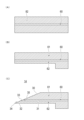
- 8(A), 8(B) and 8(C) are schematic diagrams showing the procedure for forming the injection needle of Embodiment 3.
- FIG. 9(A), 9(B) and 9(C) are a top view, a front view and a side view showing the injection needle of Embodiment 4.
- FIG. 10(A), 10(B) and 10(C) are schematic diagrams showing the procedure for forming the injection needle of Embodiment 4.
- FIG. 11(A) and 11(B) are schematic diagrams showing the procedure for forming the injection needle of Embodiment 5.
- distal end or distal end side
- proximal end or proximal end side
- axial direction the direction in which the needle body 30 of the injection needle extends.
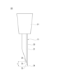
- FIG. 1 is a front view showing an injection needle assembly 20 to which the injection needle 11 of the present invention is applied.
- FIG. 2 is a schematic diagram showing a state in which the injection needle 11 of Embodiment 1 is punctured into the target site 100.
- FIG. 3(A) and 3(B) are a perspective view and a top view showing the injection needle 11 of Embodiment 1.
- FIG. 4(A) and 4(B) are a front view and a side view showing the injection needle 11 of Embodiment 1.
- FIG. 1 is a front view showing an injection needle assembly 20 to which the injection needle 11 of the present invention is applied.
- FIG. 2 is a schematic diagram showing a state in which the injection needle 11 of Embodiment 1 is punctured into the target site 100.
- FIG. 3(A) and 3(B) are a perspective view and a top view showing the injection needle 11 of Embodiment 1.
- FIG. 4(A) and 4(B) are a front view and a side view showing
- the injection needle assembly 20 has an injection needle 11 and a hub 21 that holds the proximal end of the injection needle 11 .
- a syringe (not shown) is connected to the proximal end of the hub 21 .
- the injection needle 11 is used to puncture the surface of the target site 100 such as mucosa or intradermally perpendicularly and inject the drug solution into the target site 100 .
- the term “perpendicular” refers not only to the case of forming an angle of 90 degrees with respect to the surface of the target site 100, but also to the surface of the target site 100 for the purpose of injecting the drug solution into the target site 100. Slightly slanting, substantially vertical cases are also included.
- the thickness dimension of the target site 100 such as mucous membrane or intradermal tissue differs depending on the specific tissue, but in the present invention, the target site is more than 0.1 mm and less than or equal to 2.0 mm.
- the injection needle 11 has a bevel-needle-shaped needle body 30 having a hollow portion 31 through which a drug solution can pass;
- a passage hole 33 is formed at the distal end of the needle 30 and allows the drug solution from the hollow portion 31 to pass therethrough.
- the passage hole 33 is arranged to be biased toward the side where the tip 34 of the needle body blade surface 32 is located.
- the edge of the opening edge of the passage hole 33 on the side opposite to the one-sided side is referred to as an "edge portion 35".
- a length L along the axial direction of the needle body 30 from the edge 35 to the tip 34 of the needle body blade surface 32 is 0.1 to less than 2.0 mm.
- the term "placed at one side” means that when an element is arranged on a member, the element is arranged eccentrically at a radially outward position with respect to the axis of the member.
- the passage hole 33 is arranged eccentrically at a radially outward position with respect to the axis of the needle body 30 .
- the passage hole 33 is eccentric to the side where the tip 34 of the needle blade surface 32 is located.
- the injection needle 11 can puncture the target site 100 without increasing the puncture resistance due to the needle body blade surface 32 formed at the tip of the needle body 30 .
- the passage hole 33 is arranged on the side where the tip 34 of the needle body blade surface 32 is located.
- a length L along the axial direction of the needle body 30 from the edge 35 of the passage hole 33 to the tip 34 of the needle body blade surface 32 is 0.1 to less than 2.0 mm.
- the tip 34 of the needle body blade surface 32 passes over the target site 100 and enters the tissue 101 below the target site 100. It can reduce sticking. This can prevent leakage of the liquid medicine to the underlying tissue 101 .
- the position of the passage hole 33 above the target site 100 can be reduced. As a result, leakage of the liquid medicine to the surface of the target site 100 can be prevented. Furthermore, since the needle body 30 having a relatively long needle body blade surface 32 (bevel length) can be used, the puncture resistance does not increase and the target site 100 can be punctured reliably.
- the injection needle 11 can puncture the target site 100 having a thickness of more than 0.1 mm and 2.0 mm or less without increasing the puncture resistance, and injects the drug solution into the target site 100 without causing leakage of the drug solution. be able to.
- the angle of the tip 34 of the needle blade surface 32 is preferably 30° or less. With this configuration, the target site 100 can be punctured without increasing the puncture resistance.
- the angle of the tip 34 of the needle blade surface 32 is preferably 10° or more.
- the lower limit that can be produced by grinding is about 5°, but the practical lower limit is 10° from the viewpoint of ease of grinding and mass productivity.
- the outer diameter of the needle body 30 is at least 0.20 mm or more. As the outer diameter of the needle body 30 becomes smaller, it becomes more difficult to grind the tip end 34 of the needle body blade surface 32 to an acute angle. As a result, the tip 34 of the needle body blade surface 32 has a relatively obtuse angle, increasing the puncture resistance. By setting the outer diameter of the needle 30 to 0.20 mm or more, it becomes easy to grind the tip 34 of the blade surface 32 of the needle to an acute angle. Therefore, the injection needle 11 can puncture the target site 100 without increasing the puncture resistance.
- the injection needle 11 of Embodiment 1 will be further detailed. As also shown in FIGS. 3(A), 3(B), 4(A) and 4(B), the injection needle 11 has a double tube needle structure.
- the needle body 30 has a first bevel needle 40 having a first lumen 41 and a first blade surface 42 , and a second lumen 51 and a second blade surface 52 within the first lumen 41 of the first bevel needle 40 . and a second bevel needle 50 housed in the .
- the hollow portion 31 described above is composed of the second lumen 51 of the second bevel needle 50 .
- the needle body blade surface 32 described above is composed of the first blade surface 42 of the first bevel needle 40 .
- the passage hole 33 described above is formed by the outlet 54 of the second lumen 51 of the second bevel needle 50 .
- the axial center of the needle body 30 described above corresponds to the axial center of the first bevel needle 40
- the axial direction of the needle body 30 corresponds to the axial direction of the first bevel needle 40 .
- the second bevel needle 50 has the second blade surface 52 directed in the same direction as the first blade surface 42 of the first bevel needle 40 .
- the second bevel needle 50 is further arranged to be biased toward the side where the tip 43 of the first blade surface 42 of the first bevel needle 40 is located.
- the arrangement position of the second bevel needle 50 can be restated as follows.
- the second bevel needle 50 is arranged radially outward with respect to the axis of the first bevel needle 40 and eccentrically on the side where the tip 43 of the first blade surface 42 of the first bevel needle 40 is located. there is
- the first lumen 41 of the first bevel needle 40 is sealed in the state where the second bevel needle 50 is arranged and does not pass liquid.
- the first lumen 41 is filled with a sealing material 44 (for example, a resin material) to seal the first lumen 41 .
- the sealing material 44 is removed beyond the first blade surface 42 of the first bevel needle 40 . Therefore, as shown in FIG. 2, the tip of the sealing material 44 does not extend beyond the first blade surface 42 of the first bevel needle 40 .
- the tip 53 of the second blade surface 52 of the second bevel needle 50 does not exceed the first blade surface 42 of the first bevel needle 40.
- the first blade surface 42 of the first bevel needle 40 contacts the target site 100 before the second blade surface 52 of the second bevel needle 50 .
- the injection needle 11 is punctured into the target site 100 by the first blade surface 42 of the first bevel needle 40 .
- the edge portion 35 is the edge of the opening edge of the discharge port 54 of the second lumen 51 of the second bevel needle 50 opposite to the one side.
- a length L along the axial direction of the first bevel needle 40 from the edge 35 to the tip 43 of the first blade surface 42 of the first bevel needle 40 is 0.1 to less than 2.0 mm.
- first bevel needle 40 and the second bevel needle 50 examples include stainless steel, aluminum, aluminum alloys, titanium, and titanium alloys.
- the first bevel needle 40 preferably has low puncture resistance.
- it is preferable to reduce the puncture resistance by coating the surface of the first bevel needle 40 with a coating agent made of silicone resin, fluororesin, or the like.
- the injection needle 11 having the above configuration can puncture the target site 100 having a thickness of more than 0.1 mm and 2.0 mm or less without increasing the puncture resistance, and injects the drug solution into the target site 100 without causing leakage of the drug solution. can do. Also, the injection needle 11 can be manufactured by combining the existing first bevel needle 40 and the existing second bevel needle 50 . Therefore, the injection needle 11 can be manufactured relatively easily and inexpensively.
- the second bevel needle 50 is arranged in contact with the inner peripheral surface 41 a of the first lumen 41 of the first bevel needle 40 .
- the discharge port 54 can be arranged most eccentrically, and positioning of the second bevel needle 50 with respect to the first bevel needle 40 is also facilitated.
- the thickness of the first bevel needle 40 is preferably thin. This is because the ejection port 54 can be further eccentrically arranged.
- the angle of the tip 43 of the first blade surface 42 of the first bevel needle 40 is sharper than the angle of the tip 53 of the second blade surface 52 of the second bevel needle 50 . Since the outer diameter of the first bevel needle 40 is larger than the outer diameter of the second bevel needle 50, it is easy to grind the tip 43 of the first blade surface 42 to an acute angle. Since the injection needle 11 is punctured into the target site 100 by the first blade surface 42 of the first bevel needle 40, the puncture resistance of the injection needle 11 is increased even if the second bevel needle 50 having a small outer diameter is used. never. As a result of being able to use a second bevel needle 50 with a smaller outer diameter, the outlet 54 can be positioned more eccentrically.
- the first bevel needle 40 has a needle tube of 27G (outer diameter 0.40 mm), inner diameter of 0.22 mm, and bevel length of the first blade surface 42 of 1.85 mm.
- the second bevel needle 50 has a needle tube of 36G (outer diameter 0.10 mm), inner diameter of 0.04 mm, and bevel length of the second blade surface 52 of 0.15 mm.
- the length L is approximately 0.3 mm.
- the target site 100 having a thickness of more than 0.1 mm and 2.0 mm or less can be punctured without increasing the puncture resistance, and the liquid medicine can be injected into the target site 100 without causing leakage of the liquid medicine. .
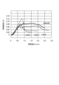
- FIG. 5 is a graph showing experimental results of the puncture resistance of the injection needle 11.
- the injection needle 11 of Embodiment 1 is a combination of the first bevel needle 40 and the second bevel needle 50 described above.
- the needle tube of Comparative Example 1 has a diameter of 27G (outer diameter 0.40 mm) and a bevel length of 1.85 mm.
- the needle tube of Comparative Example 2 has a diameter of 36G (outer diameter of 0.10 mm) and a bevel length of 0.52 mm.
- the needle tube of Comparative Example 3 has a diameter of 34G (outer diameter 0.20 mm) and a bevel length of 0.3 mm.
- the injection needle 11 of Embodiment 1 had a puncture resistance of about 0.082N.
- the needle tube of Comparative Example 1 had a puncture resistance of about 0.065N.
- the needle tube of Comparative Example 2 had a puncture resistance of about 0.073N.
- the needle tube of Comparative Example 3 had a puncture resistance of about 0.114N.
- the puncture resistance was slightly higher than that of the needle tube of Comparative Example 1.
- the reason for this is presumed to be a processing problem. That is, in Embodiment 1, the sealing material 44 partially adheres to the first blade surface 42 of the first bevel needle 40, and this is thought to increase the puncture resistance compared to Comparative Example 1.
- the injection needle 11 of Embodiment 1 had similar puncture resistance to the needle tube of Comparative Example 2 (36 G, bevel length 0.52 mm).
- the injection needle 11 of Embodiment 1 had a smaller puncture resistance than the needle tube of Comparative Example 3 (34 G, bevel length 0.3 mm).
- the injection needle 11 of Embodiment 1 is an injection needle 11 that punctures the surface of a target site 100 such as a mucous membrane or intracutaneously and injects a drug solution into the target site 100 .
- the injection needle 11 includes a bevel-needle-shaped needle body 30 having a hollow portion 31 through which a drug solution can pass; and a passage hole 33 that is formed at the tip of the and allows the chemical solution from the hollow portion 31 to pass through.
- the passage hole 33 is arranged to be biased toward the side where the tip 34 of the needle body blade surface 32 is located.
- the length L along the axial direction of the needle body 30 from the edge 35 of the opening edge of the passage hole 33 opposite to the one-sided side to the tip 34 of the needle body blade surface 32 is 0.1 to 2.0. less than 0 mm.
- the injection needle 11 configured in this way can puncture the target site 100 without increasing the puncture resistance due to the needle body blade surface 32 formed at the tip of the needle body 30 .
- the passage hole 33 is arranged on the side where the tip 34 of the needle body blade surface 32 is located.
- a length L along the axial direction of the needle body 30 from the edge 35 of the passage hole 33 to the tip 34 of the needle body blade surface 32 is 0.1 to less than 2.0 mm.
- the tip 34 of the needle body blade surface 32 passes over the target site 100 and enters the tissue 101 below the target site 100. It can reduce sticking. This can prevent leakage of the liquid medicine to the underlying tissue 101 .
- the position of the passage hole 33 above the target site 100 can be reduced. As a result, leakage of the liquid medicine to the surface of the target site 100 can be prevented. Furthermore, since the needle body 30 having a relatively long needle body blade surface 32 (bevel length) can be used, the puncture resistance does not increase and the target site 100 can be punctured reliably. Therefore, the injection needle 11 can puncture the target site 100 having a thickness of more than 0.1 mm and 2.0 mm or less without increasing the puncture resistance, and injects the drug solution into the target site 100 without causing leakage of the drug solution. can do.
- the angle of the tip 34 of the needle blade surface 32 is 30° or less. With this configuration, the target site 100 can be punctured without increasing the puncture resistance.
- the outer diameter of the needle body 30 is at least 0.20 mm or more.
- the needle body 30 has a first bevel needle 40 having a first lumen 41 and a first blade surface 42 , and a second lumen 51 and a second blade surface 52 within the first lumen 41 of the first bevel needle 40 . and a second bevel needle 50 housed in the .
- the hollow portion 31 is composed of the second lumen 51 of the second bevel needle 50
- the needle body cutting surface 32 is composed of the first cutting surface 42 of the first bevel needle 40
- the passage hole 33 is composed of the second bevel needle. It is composed of 50 second lumens 51 and outlets 54 .
- the second bevel needle 50 has the second blade surface 52 directed in the same direction as the first blade surface 42 of the first bevel needle 40, and the tip 43 of the first blade surface 42 of the first bevel needle 40 is positioned. placed to one side.
- the first lumen 41 of the first bevel needle 40 is sealed with the second bevel needle 50 placed thereon, and the tip 53 of the second blade surface 52 of the second bevel needle 50 is the first lumen 41 of the first bevel needle 40 .
- the injection needle 11 can puncture the target site 100 having a thickness of more than 0.1 mm and not more than 2.0 mm without increasing the puncture resistance, and the target site 100 can be prevented from leaking the drug solution.
- a drug solution can be injected inside.
- the injection needle 11 can be manufactured by combining the existing first bevel needle 40 and the existing second bevel needle 50 . Therefore, injection needle 11 can be manufactured relatively easily.
- the second bevel needle 50 is arranged in contact with the inner peripheral surface 41 a of the first lumen 41 of the first bevel needle 40 .
- the discharge port 54 can be arranged with the most eccentricity, and positioning of the second bevel needle 50 with respect to the first bevel needle 40 is facilitated.
- the angle of the tip 43 of the first blade surface 42 of the first bevel needle 40 is sharper than the angle of the tip 53 of the second blade surface 52 of the second bevel needle 50 .
- the outer diameter of the first bevel needle 40 is larger than the outer diameter of the second bevel needle 50, so it is easy to grind the tip 43 of the first blade surface 42 to an acute angle. . Since the injection needle 11 is punctured into the target site 100 by the first blade surface 42 of the first bevel needle 40, the puncture resistance of the injection needle 11 is increased even if the second bevel needle 50 having a small outer diameter is used. never. As a result of being able to use a second bevel needle 50 with a smaller outer diameter, the outlet 54 can be positioned more eccentrically.
- the first bevel needle 40 has a needle tube of 27G (outer diameter 0.40 mm), inner diameter of 0.22 mm, and bevel length of the first blade surface 42 of 1.85 mm.
- the second bevel needle 50 has a needle tube of 36G (outer diameter 0.10 mm), inner diameter of 0.04 mm, and bevel length of the second blade surface 52 of 0.15 mm.
- a needle tube of 27G (outer diameter 0.40 mm) is used as the first bevel needle 40 .
- a needle tube of 34G outer diameter: 0.20 mm, inner diameter: 0.16 mm, wall thickness: 0.02 mm
- the degree of deviation of the discharge port 54 of the second bevel needle 50 is reduced.
- the following embodiments can be adopted.
- FIG. 6(A), 6(B) and 6(C) are a cross-sectional view showing the injection needle 12 of Embodiment 2, a cross-sectional view and a top view along line 6B-6B in FIG. 6(A). .
- the injection needle 12 of Embodiment 2 is similar to the injection needle 11 of Embodiment 1, and has a bevel needle-shaped needle body 30 having a hollow portion 31 through which a drug solution can pass, and a needle body 30 formed at the tip of the needle body 30. It has a needle body blade surface 32 that can pierce the target site 100 and a passage hole 33 that is formed at the tip of the needle body 30 and allows the drug solution from the hollow part 31 to pass therethrough.
- the passage hole 33 is arranged to be biased toward the side where the tip 34 of the needle body blade surface 32 is located.
- the length L along the axial direction of the needle body from the edge 35 of the opening edge of the passage hole 33 opposite to the one-sided side to the tip 34 of the needle body blade surface 32 is 0.1 to 2.0 mm. is less than
- the injection needle 12 of Embodiment 2 can also puncture the target site 100 having a thickness of more than 0.1 mm and 2.0 mm or less without increasing the puncture resistance, and the drug solution can be injected into the target site 100 without causing leakage of the drug solution. can be injected.
- the angle of the tip 34 of the needle blade surface 32 is 30° or less.
- the needle body 30 has an outer diameter of at least 0.20 mm.
- the needle body 30 is made of a metal material.
- metal materials include stainless steel, aluminum, aluminum alloys, titanium, and titanium alloys.
- the hollow portion 31 and the passage hole 33 described above are composed of a lumen 60 parallel to the axial direction of the needle 30 .
- the lumen 60 is formed by subjecting a solid metal material to, for example, laser machining or electrical discharge machining.
- the needle body 30 By arranging the lumen 60 to one side, the needle body 30 has a thick compressed region 61 (a region above the lumen 60 in FIG. 6A) and a thin region 62 with a small thickness (FIG. 6A). ) below the lumen 60).
- the thickness of the thinned region 62 is at least 0.02 mm or more.
- the injection needle 12 of Embodiment 2 has an uneven thickness needle structure in which a thickened area 61 and a thinned area 62 are formed. Although it is possible to arrange the lumen 60 on the axis and form a needle tube with a small outer diameter, it is not possible to secure the needle strength required for puncture. In addition, the blade surface cannot be created by grinding. Although the blade surface can be machined by electroforming or electric discharge machining, the puncture resistance can be lowered by grinding the blade surface. Therefore, by making the injection needle 12 into a needle structure with a reduced thickness, it is possible to secure the needle strength necessary for puncturing. Moreover, since the needle body blade surface 32 can be produced by grinding, the injection needle 12 with low puncture resistance can be formed.
- the reason why the thickness of the thin region 62 is set to at least 0.02 mm or more is to ensure the strength of the needle necessary for puncturing and to enable the needle body blade surface 32 to be produced by grinding.
- the needle body 30 is made of a metal material, and the hollow portion 31 and the passage hole 33 are configured by the lumen 60 parallel to the axial direction of the needle body 30. .
- the needle body 30 is formed with a compressed region 61 having a large thickness and a thin region 62 having a small thickness.
- the thickness of the thinned region 62 is at least 0.02 mm or more.
- the injection needle 12 of Embodiment 2 can also puncture the target site 100 having a thickness of more than 0.1 mm and 2.0 mm or less without increasing the puncture resistance, and the drug solution can be injected into the target site 100 without causing leakage of the drug solution. can be injected.
- the needle strength required for puncturing can be ensured, and the needle body blade surface 32 can be formed by grinding, so that the injection needle 12 with low puncture resistance can be formed.
- FIG. 3 are a cross-sectional view showing the injection needle 13 of Embodiment 3, a cross-sectional view and a top view along line 7B-7B in FIG. 7(A).
- 8(A), 8(B) and 8(C) are schematic diagrams showing the procedure for forming the injection needle 13 of Embodiment 3.
- FIG. Members common to the injection needles 11 and 12 of Embodiments 1 and 2 are denoted by the same reference numerals, and descriptions thereof are partially omitted.
- the needle body 30 is made of a metal material.
- metal materials include stainless steel, aluminum, aluminum alloys, titanium, and titanium alloys.
- the hollow portion 31 described above is composed of a lumen 70 that is concentric with the axis of the needle body 30 .
- the needle body 30 has a thickness of at least 0.02 mm.
- a pipe 71 having a lumen 70 is manufactured by electroforming.
- the needle blade face 32 is created by grinding.
- a passage hole 33 is formed at the tip of the needle body 30 by electric discharge machining or laser machining.
- the thickness of the needle body 30 is set to at least 0.02 mm or more because, as with the injection needle 12 of Embodiment 2, the strength of the needle required for puncturing is ensured, and the blade surface 32 of the needle body is created by grinding. This is to make it possible.
- the needle body 30 is made of a metal material, and the hollow part 31 is composed of the inner lumen 70 concentric with the axis of the needle body 30 .
- the needle body 30 has a thickness of at least 0.02 mm.
- the injection needle 13 of Embodiment 3 can also puncture the target site 100 having a thickness of more than 0.1 mm and 2.0 mm or less without increasing the puncture resistance, and the drug solution can be injected into the target site 100 without causing leakage of the drug solution. can be injected.
- the needle strength required for puncturing can be ensured, and the needle body blade surface 32 can be formed by grinding, so that the injection needle 12 with low puncture resistance can be formed.
- FIG. 10(A), 10(B) and 10(C) are schematic diagrams showing the procedure for forming the injection needle 14 of the fourth embodiment.
- the members common to the injection needles 11 to 13 of Embodiments 1 to 3 are denoted by the same reference numerals, and the description thereof is partially omitted.
- the injection needle 14 of Embodiment 4 has a small diameter portion 80 on the distal end side and a large diameter portion 81 on the proximal end side.
- the small diameter portion 80 of the injection needle 12 is configured similarly to the injection needle 12 of the second embodiment.
- the needle body 30 has a thick compressed region 61 (a region above the lumen 60 in FIG. 9(C)) and a thin region 62 (FIG. 9(C)). ) below the lumen 60).
- the thickness of the thinned region 62 is at least 0.02 mm or more.
- the lumen 60 of the large-diameter portion 81 of the injection needle 12 is arranged close to the axis.
- a thick-walled pipe 82 having a lumen 60 formed at its axis is prepared.
- one side (below the lumen 60) of the thick pipe 82 is shaved by electric discharge machining or polishing to form a thin region 62. As shown in FIG. 10(B), one side (below the lumen 60) of the thick pipe 82 is shaved by electric discharge machining or polishing to form a thin region 62. As shown in FIG. 10(B), one side (below the lumen 60) of the thick pipe 82 is shaved by electric discharge machining or polishing to form a thin region 62. As shown in FIG.
- the needle blade surface 32 is created by grinding.
- the reason why the thickness of the thin region 62 is set to at least 0.02 mm or more is to ensure the strength of the needle necessary for puncturing and to enable the needle body blade surface 32 to be produced by grinding.
- the injection needle 14 of Embodiment 4 can also puncture the target site 100 with a thickness of more than 0.1 mm and 2.0 mm or less without increasing the puncture resistance, and the drug solution can be injected into the target site 100 without causing leakage of the drug solution. can be injected. Furthermore, the needle strength required for puncturing can be ensured, and the needle body blade surface 32 can be formed by grinding, so that the injection needle 12 with low puncture resistance can be formed.
- Embodiment 5 modifies the procedure for forming injection needle 15 having a biased thickness needle structure (structure similar to injection needle 12 of Embodiment 2).
- 11(A) and 11(B) are schematic diagrams showing the procedure for forming the injection needle 15 of the fifth embodiment.
- a pipe 90 in which the lumens 60 are arranged side by side is produced by electroforming. Lumen 60 does not pass through pipe 90 .
- the needle blade face 32 is created by grinding until the lumen 60 appears.
- the injection needle 12 of Embodiment 5 can also puncture the target site 100 with a thickness of more than 0.1 mm and 2.0 mm or less without increasing the puncture resistance, and the drug solution can be injected into the target site 100 without causing leakage of the drug solution. can be injected. Furthermore, the needle strength required for puncturing can be ensured, and the needle body blade surface 32 can be formed by grinding, so that the injection needle 12 with low puncture resistance can be formed.
- the injection needles 11 to 15 according to the present invention have been described through Embodiments 1 to 5, but the present invention is not limited only to the contents described in the embodiments. It is possible to change.
- the angle of the tip 43 of the first blade surface 42 of the first bevel needle 40 is assumed to be sharper than the angle of the tip 53 of the second blade surface 52 of the second bevel needle 50 .
- the invention is not limited to this case.
- the angle of the tip 43 of the first blade surface 42 and the angle of the tip 53 of the second blade surface 52 are made the same angle, so that the first blade surface 42 and the second blade surface 52 can be aligned.
- Injection needle assembly 21 Hub 30 Needle 31 Hollow portion 32 Needle blade surface 33 Passing hole 34 Tip 35 Edge 40 First bevel needle 41 First lumen 41a Inner peripheral surface 42 First blade surface 43 Tip 44 Sealing material 50 Second bevel needle 51 Second lumen 52 Second blade surface 53 Tip 54 Discharge port 60 Lumen 61 Thickened region 62 Thin region 70 Lumen 71 Pipe 80 Small diameter portion 81 Large diameter portion 82 Thick pipe 90 Pipe 100 Target site 101 Underlying tissue
Landscapes
- Health & Medical Sciences (AREA)
- Vascular Medicine (AREA)
- Engineering & Computer Science (AREA)
- Anesthesiology (AREA)
- Biomedical Technology (AREA)
- Heart & Thoracic Surgery (AREA)
- Hematology (AREA)
- Life Sciences & Earth Sciences (AREA)
- Animal Behavior & Ethology (AREA)
- General Health & Medical Sciences (AREA)
- Public Health (AREA)
- Veterinary Medicine (AREA)
- Infusion, Injection, And Reservoir Apparatuses (AREA)
Abstract
Description
図1は、本発明の注射針11を適用した注射針組立体20を示す正面図である。図2は、実施形態1の注射針11を目的部位100に穿刺した状態において示す模式図である。図3(A)および図3(B)は、実施形態1の注射針11を示す斜視図および上面図である。図4(A)および図4(B)は、実施形態1の注射針11を示す正面図および側面図である。
図6(A)、図6(B)および図6(C)は、実施形態2の注射針12を示す断面図、図6(A)の6B-6B線に沿う断面図および上面図である。
図7(A)、図7(B)および図7(C)は、実施形態3の注射針13を示す断面図、図7(A)の7B-7B線に沿う断面図および上面図である。図8(A)、図8(B)および図8(C)は、実施形態3の注射針13の形成手順を示す概略図である。実施形態1および2の注射針11、12と共通する部材には同一の符号を付し、その説明は一部省略する。
図9(A)、図9(B)および図9(C)は、実施形態4の注射針14を示す上面図、正面図および側面図である。図10(A)、図10(B)および図10(C)は、実施形態4の注射針14の形成手順を示す概略図である。実施形態1~3の注射針11~13と共通する部材には同一の符号を付し、その説明は一部省略する。
実施形態5は、偏肉針構造を有する注射針15(実施形態2の注射針12と同様の構造)の形成手順を変形している。
20 注射針組立体
21 ハブ
30 針体
31 中空部
32 針体刃面
33 通過穴
34 先端
35 縁部
40 第1ベベル針
41 第1ルーメン
41a 内周面
42 第1刃面
43 先端
44 封止材料
50 第2ベベル針
51 第2ルーメン
52 第2刃面
53 先端
54 吐出口
60 ルーメン
61 圧肉領域
62 薄肉領域
70 内腔
71 パイプ
80 小径部
81 大径部
82 肉厚パイプ
90 パイプ
100 目的部位
101 下層の組織
Claims (9)
- 粘膜や皮内などの目的部位の表面に対して垂直に穿刺し、前記目的部位内に薬液を注入する注射針であって、
前記薬液が通過可能な中空部を有するベベル針形状の針体と、
前記針体の先端部に形成され前記目的部位に穿刺可能な針体刃面と、
前記針体の先端部に形成され前記中空部からの前記薬液を通過させる通過穴と、を有し、
前記通過穴は、前記針体刃面の先端が位置する側に片寄せて配置され、
前記通過穴の開口縁のうち片寄せた側とは反対側の縁部から、前記針体刃面の前記先端までの前記針体の軸方向に沿う長さが0.1~2.0mm未満である、注射針。 - 前記針体刃面の前記先端の角度が30°以下である、請求項1に記載の注射針。
- 前記針体の外径は、少なくとも、0.20mm以上である、請求項1または2に記載の注射針。
- 前記針体は、第1ルーメンと第1刃面とを有する第1ベベル針と、第2ルーメンと第2刃面とを有し前記第1ベベル針の前記第1ルーメン内に収納される第2ベベル針とを有し、
前記中空部は、前記第2ベベル針の前記第2ルーメンから構成され、
前記針体刃面は、前記第1ベベル針の前記第1刃面から構成され、
前記通過穴は、前記第2ベベル針の前記第2ルーメンの吐出口から構成され、
前記第2ベベル針は、前記第2刃面が前記第1ベベル針の前記第1刃面と同じ向きに向けられ、さらに、前記第1ベベル針の前記第1刃面の先端が位置する側に片寄せて配置され、
前記第1ベベル針の前記第1ルーメンは、前記第2ベベル針を配置した状態において封止され、
前記第2ベベル針の前記第2刃面の先端は、前記第1ベベル針の前記第1刃面を越えない、請求項1~3のいずれか1項に記載の注射針。 - 前記第2ベベル針は、前記第1ベベル針の前記第1ルーメンの内周面に接触して配置される、請求項4に記載の注射針。
- 前記第1ベベル針の前記第1刃面の前記先端の角度は、前記第2ベベル針の前記第2刃面の前記先端の角度よりも鋭角である、請求項4または5に記載の注射針。
- 前記第1ベベル針は、27G(外径0.40mm)、内径が0.22mm、前記第1刃面のベベル長が1.85mmの針管を有し、
前記第2ベベル針は、36G(外径0.10mm)、内径が0.04mm、前記第2刃面のベベル長が0.15mmの針管を有する、請求項4~6のいずれか1項に記載の注射針。 - 前記針体は、金属材料から形成され、
前記中空部および前記通過穴は、前記針体の軸方向と平行なルーメンから構成され、
前記針体は、前記ルーメンを片寄せて配置することによって、肉厚が厚い圧肉領域と肉厚が薄い薄肉領域とが形成され、
前記薄肉領域における肉厚は、少なくとも、0.02mm以上である、請求項1~3のいずれか1項に記載の注射針。 - 前記針体は、金属材料から形成され、
前記中空部は、前記針体の軸心と同心状の内腔から構成され、
前記針体の肉厚は、少なくとも、0.02mm以上である、請求項1~3のいずれか1項に記載の注射針。
Priority Applications (3)
| Application Number | Priority Date | Filing Date | Title |
|---|---|---|---|
| JP2023552800A JPWO2023058473A1 (ja) | 2021-10-07 | 2022-09-26 | |
| US18/696,401 US20250041532A1 (en) | 2021-10-07 | 2022-09-26 | Injection needle |
| EP22878344.5A EP4414007A4 (en) | 2021-10-07 | 2022-09-26 | INJECTION NEEDLE |
Applications Claiming Priority (2)
| Application Number | Priority Date | Filing Date | Title |
|---|---|---|---|
| JP2021-165236 | 2021-10-07 | ||
| JP2021165236 | 2021-10-07 |
Publications (1)
| Publication Number | Publication Date |
|---|---|
| WO2023058473A1 true WO2023058473A1 (ja) | 2023-04-13 |
Family
ID=85804210
Family Applications (1)
| Application Number | Title | Priority Date | Filing Date |
|---|---|---|---|
| PCT/JP2022/035572 Ceased WO2023058473A1 (ja) | 2021-10-07 | 2022-09-26 | 注射針 |
Country Status (4)
| Country | Link |
|---|---|
| US (1) | US20250041532A1 (ja) |
| EP (1) | EP4414007A4 (ja) |
| JP (1) | JPWO2023058473A1 (ja) |
| WO (1) | WO2023058473A1 (ja) |
Citations (7)
| Publication number | Priority date | Publication date | Assignee | Title |
|---|---|---|---|---|
| JP2008529594A (ja) * | 2005-02-04 | 2008-08-07 | ボストン サイエンティフィック リミティド | ノンコアリングニードル及びその製造方法 |
| US8480645B1 (en) * | 2008-08-22 | 2013-07-09 | Sambhu N. Choudhury | Multi-dose device for insertion into a vial and method of using the same |
| US20140025035A1 (en) * | 2012-07-17 | 2014-01-23 | Cook Medical Technologies Llc | Multi-lumen biologic-delivering device |
| US20170312432A1 (en) * | 2016-04-29 | 2017-11-02 | HUANG Hsiang | Needle structure |
| JP2018138095A (ja) * | 2017-02-24 | 2018-09-06 | テルモ株式会社 | 医療用デバイス |
| JP2021019841A (ja) * | 2019-07-26 | 2021-02-18 | テルモ株式会社 | 穿刺針 |
| JP2021165236A (ja) | 2020-04-06 | 2021-10-14 | 株式会社ファンケル | アトロジン−1発現抑制剤 |
Family Cites Families (2)
| Publication number | Priority date | Publication date | Assignee | Title |
|---|---|---|---|---|
| US4020837A (en) * | 1975-11-04 | 1977-05-03 | Pharmaco, Inc. (Entire) | Hollow piercing tip for vial stoppers |
| JP5500742B2 (ja) * | 2012-03-19 | 2014-05-21 | 株式会社ユニシス | 脊椎くも膜下麻酔針の製造方法 |
-
2022
- 2022-09-26 WO PCT/JP2022/035572 patent/WO2023058473A1/ja not_active Ceased
- 2022-09-26 EP EP22878344.5A patent/EP4414007A4/en active Pending
- 2022-09-26 JP JP2023552800A patent/JPWO2023058473A1/ja active Pending
- 2022-09-26 US US18/696,401 patent/US20250041532A1/en active Pending
Patent Citations (8)
| Publication number | Priority date | Publication date | Assignee | Title |
|---|---|---|---|---|
| JP2008529594A (ja) * | 2005-02-04 | 2008-08-07 | ボストン サイエンティフィック リミティド | ノンコアリングニードル及びその製造方法 |
| US8480645B1 (en) * | 2008-08-22 | 2013-07-09 | Sambhu N. Choudhury | Multi-dose device for insertion into a vial and method of using the same |
| US20140025035A1 (en) * | 2012-07-17 | 2014-01-23 | Cook Medical Technologies Llc | Multi-lumen biologic-delivering device |
| US20170312432A1 (en) * | 2016-04-29 | 2017-11-02 | HUANG Hsiang | Needle structure |
| JP2018138095A (ja) * | 2017-02-24 | 2018-09-06 | テルモ株式会社 | 医療用デバイス |
| JP6765990B2 (ja) | 2017-02-24 | 2020-10-07 | テルモ株式会社 | 医療用デバイス |
| JP2021019841A (ja) * | 2019-07-26 | 2021-02-18 | テルモ株式会社 | 穿刺針 |
| JP2021165236A (ja) | 2020-04-06 | 2021-10-14 | 株式会社ファンケル | アトロジン−1発現抑制剤 |
Non-Patent Citations (1)
| Title |
|---|
| See also references of EP4414007A4 |
Also Published As
| Publication number | Publication date |
|---|---|
| US20250041532A1 (en) | 2025-02-06 |
| EP4414007A1 (en) | 2024-08-14 |
| EP4414007A4 (en) | 2025-09-24 |
| JPWO2023058473A1 (ja) | 2023-04-13 |
Similar Documents
| Publication | Publication Date | Title |
|---|---|---|
| EP3522974B1 (en) | Septum housing for a catheter | |
| CN105102046B (zh) | 药液注射器 | |
| JP6088640B2 (ja) | 薬剤注射装置 | |
| US10918807B2 (en) | Disposable pen needle with abbreviated non-patient end, and reusable pen interface | |
| JP2011011000A (ja) | 針管、医療器具および医療器具の製造方法 | |
| TW201113060A (en) | Injection needles assembly body and drug injection device | |
| WO2011122224A1 (ja) | 注射針組立体および薬剤注射装置 | |
| KR20220016118A (ko) | 주입 포트를 가지는 카테터 조립체 및 관련 방법 | |
| EP2620172A1 (en) | Method of assembling medicament injection device | |
| WO2016052169A1 (ja) | 注射針組立体及び薬剤注射装置 | |
| WO2015098645A1 (ja) | 注射針 | |
| WO2023058473A1 (ja) | 注射針 | |
| EP2623148A1 (en) | Medical instrument with attached needle | |
| JP2006055674A (ja) | 留置針組立体 | |
| CN210992268U (zh) | 一种输液港用穿刺针针头及其制成的输液港用穿刺针 | |
| CN203763666U (zh) | 一种止血阀和导引鞘 | |
| CN211751520U (zh) | 用于穿刺输液港的无损伤针 | |
| JP2022151079A (ja) | 中空穿刺針およびそれを用いた穿刺針組立体 | |
| WO2012157318A1 (ja) | 注射針組立体及び薬剤注射装置 | |
| CN211357355U (zh) | 一种一次性使用无菌导引器械套装 | |
| CN109260547B (zh) | 静脉输液港用无损伤针 | |
| CN110354334B (zh) | 输液港用穿刺针针头及其制成的输液港用穿刺针 | |
| WO2026070072A1 (ja) | 注射針、注射針組立体及び注射器 | |
| JPWO2023058473A5 (ja) | ||
| JP2017051806A (ja) | 接続部材 |
Legal Events
| Date | Code | Title | Description |
|---|---|---|---|
| 121 | Ep: the epo has been informed by wipo that ep was designated in this application |
Ref document number: 22878344 Country of ref document: EP Kind code of ref document: A1 |
|
| WWE | Wipo information: entry into national phase |
Ref document number: 2023552800 Country of ref document: JP |
|
| WWE | Wipo information: entry into national phase |
Ref document number: 18696401 Country of ref document: US |
|
| WWE | Wipo information: entry into national phase |
Ref document number: 2022878344 Country of ref document: EP |
|
| NENP | Non-entry into the national phase |
Ref country code: DE |
|
| ENP | Entry into the national phase |
Ref document number: 2022878344 Country of ref document: EP Effective date: 20240507 |