WO2023058488A1 - 画像投影装置および画像投影方法 - Google Patents
画像投影装置および画像投影方法 Download PDFInfo
- Publication number
- WO2023058488A1 WO2023058488A1 PCT/JP2022/035716 JP2022035716W WO2023058488A1 WO 2023058488 A1 WO2023058488 A1 WO 2023058488A1 JP 2022035716 W JP2022035716 W JP 2022035716W WO 2023058488 A1 WO2023058488 A1 WO 2023058488A1
- Authority
- WO
- WIPO (PCT)
- Prior art keywords
- image
- light
- projection device
- optical
- section
- Prior art date
- Legal status (The legal status is an assumption and is not a legal conclusion. Google has not performed a legal analysis and makes no representation as to the accuracy of the status listed.)
- Ceased
Links
Images







Classifications
-
- G—PHYSICS
- G02—OPTICS
- G02B—OPTICAL ELEMENTS, SYSTEMS OR APPARATUS
- G02B27/00—Optical systems or apparatus not provided for by any of the groups G02B1/00 - G02B26/00, G02B30/00
- G02B27/01—Head-up displays
-
- G—PHYSICS
- G02—OPTICS
- G02B—OPTICAL ELEMENTS, SYSTEMS OR APPARATUS
- G02B27/00—Optical systems or apparatus not provided for by any of the groups G02B1/00 - G02B26/00, G02B30/00
- G02B27/01—Head-up displays
- G02B27/0101—Head-up displays characterised by optical features
-
- B—PERFORMING OPERATIONS; TRANSPORTING
- B60—VEHICLES IN GENERAL
- B60K—ARRANGEMENT OR MOUNTING OF PROPULSION UNITS OR OF TRANSMISSIONS IN VEHICLES; ARRANGEMENT OR MOUNTING OF PLURAL DIVERSE PRIME-MOVERS IN VEHICLES; AUXILIARY DRIVES FOR VEHICLES; INSTRUMENTATION OR DASHBOARDS FOR VEHICLES; ARRANGEMENTS IN CONNECTION WITH COOLING, AIR INTAKE, GAS EXHAUST OR FUEL SUPPLY OF PROPULSION UNITS IN VEHICLES
- B60K35/00—Instruments specially adapted for vehicles; Arrangement of instruments in or on vehicles
- B60K35/20—Output arrangements, i.e. from vehicle to user, associated with vehicle functions or specially adapted therefor
- B60K35/21—Output arrangements, i.e. from vehicle to user, associated with vehicle functions or specially adapted therefor using visual output, e.g. blinking lights or matrix displays
- B60K35/213—Virtual instruments
-
- B—PERFORMING OPERATIONS; TRANSPORTING
- B60—VEHICLES IN GENERAL
- B60K—ARRANGEMENT OR MOUNTING OF PROPULSION UNITS OR OF TRANSMISSIONS IN VEHICLES; ARRANGEMENT OR MOUNTING OF PLURAL DIVERSE PRIME-MOVERS IN VEHICLES; AUXILIARY DRIVES FOR VEHICLES; INSTRUMENTATION OR DASHBOARDS FOR VEHICLES; ARRANGEMENTS IN CONNECTION WITH COOLING, AIR INTAKE, GAS EXHAUST OR FUEL SUPPLY OF PROPULSION UNITS IN VEHICLES
- B60K35/00—Instruments specially adapted for vehicles; Arrangement of instruments in or on vehicles
- B60K35/20—Output arrangements, i.e. from vehicle to user, associated with vehicle functions or specially adapted therefor
- B60K35/21—Output arrangements, i.e. from vehicle to user, associated with vehicle functions or specially adapted therefor using visual output, e.g. blinking lights or matrix displays
- B60K35/23—Head-up displays [HUD]
- B60K35/231—Head-up displays [HUD] characterised by their arrangement or structure for integration into vehicles
-
- B—PERFORMING OPERATIONS; TRANSPORTING
- B60—VEHICLES IN GENERAL
- B60K—ARRANGEMENT OR MOUNTING OF PROPULSION UNITS OR OF TRANSMISSIONS IN VEHICLES; ARRANGEMENT OR MOUNTING OF PLURAL DIVERSE PRIME-MOVERS IN VEHICLES; AUXILIARY DRIVES FOR VEHICLES; INSTRUMENTATION OR DASHBOARDS FOR VEHICLES; ARRANGEMENTS IN CONNECTION WITH COOLING, AIR INTAKE, GAS EXHAUST OR FUEL SUPPLY OF PROPULSION UNITS IN VEHICLES
- B60K35/00—Instruments specially adapted for vehicles; Arrangement of instruments in or on vehicles
- B60K35/20—Output arrangements, i.e. from vehicle to user, associated with vehicle functions or specially adapted therefor
- B60K35/29—Instruments characterised by the way in which information is handled, e.g. showing information on plural displays or prioritising information according to driving conditions
-
- B—PERFORMING OPERATIONS; TRANSPORTING
- B60—VEHICLES IN GENERAL
- B60K—ARRANGEMENT OR MOUNTING OF PROPULSION UNITS OR OF TRANSMISSIONS IN VEHICLES; ARRANGEMENT OR MOUNTING OF PLURAL DIVERSE PRIME-MOVERS IN VEHICLES; AUXILIARY DRIVES FOR VEHICLES; INSTRUMENTATION OR DASHBOARDS FOR VEHICLES; ARRANGEMENTS IN CONNECTION WITH COOLING, AIR INTAKE, GAS EXHAUST OR FUEL SUPPLY OF PROPULSION UNITS IN VEHICLES
- B60K35/00—Instruments specially adapted for vehicles; Arrangement of instruments in or on vehicles
- B60K35/50—Instruments characterised by their means of attachment to or integration in the vehicle
-
- B—PERFORMING OPERATIONS; TRANSPORTING
- B60—VEHICLES IN GENERAL
- B60K—ARRANGEMENT OR MOUNTING OF PROPULSION UNITS OR OF TRANSMISSIONS IN VEHICLES; ARRANGEMENT OR MOUNTING OF PLURAL DIVERSE PRIME-MOVERS IN VEHICLES; AUXILIARY DRIVES FOR VEHICLES; INSTRUMENTATION OR DASHBOARDS FOR VEHICLES; ARRANGEMENTS IN CONNECTION WITH COOLING, AIR INTAKE, GAS EXHAUST OR FUEL SUPPLY OF PROPULSION UNITS IN VEHICLES
- B60K35/00—Instruments specially adapted for vehicles; Arrangement of instruments in or on vehicles
- B60K35/80—Arrangements for controlling instruments
- B60K35/81—Arrangements for controlling instruments for controlling displays
-
- G—PHYSICS
- G02—OPTICS
- G02B—OPTICAL ELEMENTS, SYSTEMS OR APPARATUS
- G02B27/00—Optical systems or apparatus not provided for by any of the groups G02B1/00 - G02B26/00, G02B30/00
- G02B27/01—Head-up displays
- G02B27/0149—Head-up displays characterised by mechanical features
-
- G—PHYSICS
- G02—OPTICS
- G02B—OPTICAL ELEMENTS, SYSTEMS OR APPARATUS
- G02B27/00—Optical systems or apparatus not provided for by any of the groups G02B1/00 - G02B26/00, G02B30/00
- G02B27/01—Head-up displays
- G02B27/0179—Display position adjusting means not related to the information to be displayed
-
- B—PERFORMING OPERATIONS; TRANSPORTING
- B60—VEHICLES IN GENERAL
- B60K—ARRANGEMENT OR MOUNTING OF PROPULSION UNITS OR OF TRANSMISSIONS IN VEHICLES; ARRANGEMENT OR MOUNTING OF PLURAL DIVERSE PRIME-MOVERS IN VEHICLES; AUXILIARY DRIVES FOR VEHICLES; INSTRUMENTATION OR DASHBOARDS FOR VEHICLES; ARRANGEMENTS IN CONNECTION WITH COOLING, AIR INTAKE, GAS EXHAUST OR FUEL SUPPLY OF PROPULSION UNITS IN VEHICLES
- B60K2360/00—Indexing scheme associated with groups B60K35/00 or B60K37/00 relating to details of instruments or dashboards
- B60K2360/16—Type of output information
- B60K2360/167—Vehicle dynamics information
-
- B—PERFORMING OPERATIONS; TRANSPORTING
- B60—VEHICLES IN GENERAL
- B60K—ARRANGEMENT OR MOUNTING OF PROPULSION UNITS OR OF TRANSMISSIONS IN VEHICLES; ARRANGEMENT OR MOUNTING OF PLURAL DIVERSE PRIME-MOVERS IN VEHICLES; AUXILIARY DRIVES FOR VEHICLES; INSTRUMENTATION OR DASHBOARDS FOR VEHICLES; ARRANGEMENTS IN CONNECTION WITH COOLING, AIR INTAKE, GAS EXHAUST OR FUEL SUPPLY OF PROPULSION UNITS IN VEHICLES
- B60K2360/00—Indexing scheme associated with groups B60K35/00 or B60K37/00 relating to details of instruments or dashboards
- B60K2360/18—Information management
- B60K2360/182—Distributing information between displays
-
- B—PERFORMING OPERATIONS; TRANSPORTING
- B60—VEHICLES IN GENERAL
- B60K—ARRANGEMENT OR MOUNTING OF PROPULSION UNITS OR OF TRANSMISSIONS IN VEHICLES; ARRANGEMENT OR MOUNTING OF PLURAL DIVERSE PRIME-MOVERS IN VEHICLES; AUXILIARY DRIVES FOR VEHICLES; INSTRUMENTATION OR DASHBOARDS FOR VEHICLES; ARRANGEMENTS IN CONNECTION WITH COOLING, AIR INTAKE, GAS EXHAUST OR FUEL SUPPLY OF PROPULSION UNITS IN VEHICLES
- B60K2360/00—Indexing scheme associated with groups B60K35/00 or B60K37/00 relating to details of instruments or dashboards
- B60K2360/20—Optical features of instruments
- B60K2360/23—Optical features of instruments using reflectors
-
- B—PERFORMING OPERATIONS; TRANSPORTING
- B60—VEHICLES IN GENERAL
- B60K—ARRANGEMENT OR MOUNTING OF PROPULSION UNITS OR OF TRANSMISSIONS IN VEHICLES; ARRANGEMENT OR MOUNTING OF PLURAL DIVERSE PRIME-MOVERS IN VEHICLES; AUXILIARY DRIVES FOR VEHICLES; INSTRUMENTATION OR DASHBOARDS FOR VEHICLES; ARRANGEMENTS IN CONNECTION WITH COOLING, AIR INTAKE, GAS EXHAUST OR FUEL SUPPLY OF PROPULSION UNITS IN VEHICLES
- B60K2360/00—Indexing scheme associated with groups B60K35/00 or B60K37/00 relating to details of instruments or dashboards
- B60K2360/20—Optical features of instruments
- B60K2360/25—Optical features of instruments using filters
-
- B—PERFORMING OPERATIONS; TRANSPORTING
- B60—VEHICLES IN GENERAL
- B60K—ARRANGEMENT OR MOUNTING OF PROPULSION UNITS OR OF TRANSMISSIONS IN VEHICLES; ARRANGEMENT OR MOUNTING OF PLURAL DIVERSE PRIME-MOVERS IN VEHICLES; AUXILIARY DRIVES FOR VEHICLES; INSTRUMENTATION OR DASHBOARDS FOR VEHICLES; ARRANGEMENTS IN CONNECTION WITH COOLING, AIR INTAKE, GAS EXHAUST OR FUEL SUPPLY OF PROPULSION UNITS IN VEHICLES
- B60K2360/00—Indexing scheme associated with groups B60K35/00 or B60K37/00 relating to details of instruments or dashboards
- B60K2360/20—Optical features of instruments
- B60K2360/31—Virtual images
-
- B—PERFORMING OPERATIONS; TRANSPORTING
- B60—VEHICLES IN GENERAL
- B60K—ARRANGEMENT OR MOUNTING OF PROPULSION UNITS OR OF TRANSMISSIONS IN VEHICLES; ARRANGEMENT OR MOUNTING OF PLURAL DIVERSE PRIME-MOVERS IN VEHICLES; AUXILIARY DRIVES FOR VEHICLES; INSTRUMENTATION OR DASHBOARDS FOR VEHICLES; ARRANGEMENTS IN CONNECTION WITH COOLING, AIR INTAKE, GAS EXHAUST OR FUEL SUPPLY OF PROPULSION UNITS IN VEHICLES
- B60K2360/00—Indexing scheme associated with groups B60K35/00 or B60K37/00 relating to details of instruments or dashboards
- B60K2360/20—Optical features of instruments
- B60K2360/33—Illumination features
- B60K2360/334—Projection means
-
- B—PERFORMING OPERATIONS; TRANSPORTING
- B60—VEHICLES IN GENERAL
- B60K—ARRANGEMENT OR MOUNTING OF PROPULSION UNITS OR OF TRANSMISSIONS IN VEHICLES; ARRANGEMENT OR MOUNTING OF PLURAL DIVERSE PRIME-MOVERS IN VEHICLES; AUXILIARY DRIVES FOR VEHICLES; INSTRUMENTATION OR DASHBOARDS FOR VEHICLES; ARRANGEMENTS IN CONNECTION WITH COOLING, AIR INTAKE, GAS EXHAUST OR FUEL SUPPLY OF PROPULSION UNITS IN VEHICLES
- B60K2360/00—Indexing scheme associated with groups B60K35/00 or B60K37/00 relating to details of instruments or dashboards
- B60K2360/20—Optical features of instruments
- B60K2360/33—Illumination features
- B60K2360/336—Light guides
-
- B—PERFORMING OPERATIONS; TRANSPORTING
- B60—VEHICLES IN GENERAL
- B60K—ARRANGEMENT OR MOUNTING OF PROPULSION UNITS OR OF TRANSMISSIONS IN VEHICLES; ARRANGEMENT OR MOUNTING OF PLURAL DIVERSE PRIME-MOVERS IN VEHICLES; AUXILIARY DRIVES FOR VEHICLES; INSTRUMENTATION OR DASHBOARDS FOR VEHICLES; ARRANGEMENTS IN CONNECTION WITH COOLING, AIR INTAKE, GAS EXHAUST OR FUEL SUPPLY OF PROPULSION UNITS IN VEHICLES
- B60K35/00—Instruments specially adapted for vehicles; Arrangement of instruments in or on vehicles
- B60K35/20—Output arrangements, i.e. from vehicle to user, associated with vehicle functions or specially adapted therefor
- B60K35/21—Output arrangements, i.e. from vehicle to user, associated with vehicle functions or specially adapted therefor using visual output, e.g. blinking lights or matrix displays
- B60K35/23—Head-up displays [HUD]
-
- G—PHYSICS
- G02—OPTICS
- G02B—OPTICAL ELEMENTS, SYSTEMS OR APPARATUS
- G02B27/00—Optical systems or apparatus not provided for by any of the groups G02B1/00 - G02B26/00, G02B30/00
- G02B27/01—Head-up displays
- G02B27/0149—Head-up displays characterised by mechanical features
- G02B2027/0154—Head-up displays characterised by mechanical features with movable elements
-
- G—PHYSICS
- G02—OPTICS
- G02B—OPTICAL ELEMENTS, SYSTEMS OR APPARATUS
- G02B27/00—Optical systems or apparatus not provided for by any of the groups G02B1/00 - G02B26/00, G02B30/00
- G02B27/01—Head-up displays
- G02B27/0179—Display position adjusting means not related to the information to be displayed
- G02B2027/0183—Adaptation to parameters characterising the motion of the vehicle
Definitions
- the present disclosure relates to an image projection device, and more particularly to an image projection device and an image projection method for projecting a projection image onto a display unit for displaying a virtual image.
- instrument panels that light up icons have been used as devices for displaying various types of information in vehicles.
- image display device it has been proposed to embed an image display device in the instrument panel or to configure the entire instrument panel with an image display device.
- HUD Head Up Display
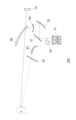
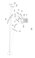
- FIGS. 6A, 6B, and 6C are schematic diagrams showing an information presentation method using the conventionally proposed HUD device 1.
- FIG. FIG. 6A shows the device layout inside the vehicle.
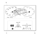
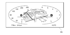
- FIG. 6B shows an instrument image 2a displayed on the meter section 2.
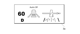
- FIG. 6C shows an auxiliary image 3a projected as virtual image 3.
- a meter section 2 is installed in the vehicle separately from the HUD device 1, and the virtual image 3 is projected from the HUD device 1 through the windshield 4.
- the meters stipulated by law are displayed in the meter section 2 as an image 2a of the meters.
- a supplementary image 3 a for assisting driving is projected as a virtual image 3 .
- the virtual image 3 is projected several degrees (4 degrees in FIG. 6A) downward from the horizontal direction, so that the driver 5 can receive supplementary information. It is possible to reduce the movement of the line of sight for visual recognition. By moving the line of sight further downward (20 degrees in FIG. 6A), the driver 5 can better visually recognize the gauges displayed on the meter section 2 .
- the HUD device 1 and the meter section 2 must be arranged in the instrument panel of the vehicle, so it is difficult to save space.
- the position where the meter unit 2 is installed is inevitably determined at a position where the driver 5 can visually recognize it well, there is a problem that the degree of freedom in design when arranging the HUD device 1 is low.
- the applicant of the present application has proposed an image projection apparatus that displays a plurality of images in one image irradiation unit and splits the optical path of each image by a light splitting unit such as a prism to save space. .
- FIG. 12 is a schematic diagram showing a conventional image projection device for projecting a plurality of images on one screen.
- the conventional image projection device includes an image irradiation section 1B, a reflecting mirror 2B, a free-form surface mirror 3B, a light branching section 4B, a free-form surface mirror 5B, and a windshield 6B.
- part of the light emitted from the image irradiation unit 1B is branched by the light branching unit 4B and reflected by the free-form surface mirror 5B, the free-form surface mirror 3B and the windshield 6B, and is projected onto the driver's viewpoint.
- a virtual image 8B is formed in the distance.
- Another part of the light emitted from the image irradiation unit 1B is reflected by the reflector 2B, the free-form surface mirror 3B, and the windshield 6B, reaches the driver's viewpoint, and forms a virtual image 7B in the vicinity. .
- the virtual image 8B is projected several degrees below the horizontal direction (about 15 m from the driver in FIG. 12), and the driver's line of sight movement for visually recognizing the driving support information is reduced. be able to. Further, a virtual image 7B is projected further downward near (about 3 m from the driver in FIG. 12), and by moving the line of sight, the vehicle speed display and the like can be visually recognized well.
- the vehicle itself and the image projection device vibrate depending on the running state and the road surface condition, so there is a problem that the image forming positions of the virtual images 7B and 8B are displaced by the vibration and the visibility is lowered. there were.
- FIG. 13 is a schematic diagram showing the display area displayed by the image irradiation unit 1B in the conventional image projection device.
- the total display area 1a in the image irradiation section 1B indicates the entire area in which an image can be displayed.
- the entire display area 1a is provided with a near display area 1b for displaying a near image and a far display area 1c for displaying a far image.
- the light that irradiates the near image displayed in the near display area 1b forms a virtual image 7B in the near area via the reflecting mirror 2B, and is displayed in the far display area 1c.
- the light that irradiates the distant image is imaged as a virtual image 8B in the distance via the light branching portion 4B.
- the imaging positions of the virtual images 7B and 8B fluctuate with respect to the background, resulting in a problem of reduced image visibility.
- a sensor for detecting vehicle vibrations In order to suppress the change in the imaging positions of the virtual images 7B and 8B due to vibrations during vehicle travel, a sensor for detecting vehicle vibrations is provided. A method of correcting the image display position is conceivable.
- the sensor detects vibration of the vehicle, it calculates the vibration direction and the amount of displacement, and changes the display positions of the near display area 1b and the far display area 1c within the margin areas 1d and 1e, respectively.
- the displacement of the virtual images 7B and 8B due to vibration is offset by the displacement within the margin areas 1d and 1e, thereby suppressing the change in the imaging positions of the near image and the far image.
- the margin areas 1d and 1e are secured within the entire display area 1a in order to cancel the vibration. need to keep For example, as shown in FIG. 13, when a displacement amount of about 15% is secured above and below the near display area 1b and the far display area 1c, the displayable image size is reduced by 30%. do. Therefore, the image size that can be formed as the virtual images 7B and 8B cannot be increased, and the visibility of the near and far images displayed as the virtual images 7B and 8B is reduced.
- An object of the present disclosure is to provide an image projection device capable of saving space and improving the degree of design freedom while displaying instruments and projecting an auxiliary image as a virtual image.
- the present disclosure provides an image projection device and an image projection method that can improve the visibility of an image by suppressing fluctuations in the imaging position due to vehicle vibration while ensuring an effective image display area. for the purpose.
- An image projection device is an image projection device that irradiates a projection image onto a display unit for displaying a virtual image, and includes an image irradiating unit that irradiates an image, and at least a first light that irradiates the image. a light branching unit that branches into image light and a second image light; a first optical unit that irradiates the first image light as the projected image in a viewing direction through the display unit; a second optical unit that irradiates the second image light in the viewpoint direction;
- the image emitted from the image irradiation unit is split into the first image light and the second image light by the light splitting unit, and the first image light is sent to the display unit by the first optical unit.
- the second image light is emitted by the second optical section without passing through the display section.
- An image projection device is an image projection device that irradiates a projection image onto a display unit for displaying a virtual image, and includes an image irradiation unit that irradiates a first image, and the first image projected through the display unit.
- a first optical unit that irradiates one image as first image light in a viewpoint direction, and a first optical drive unit that changes an incident angle of the first image light with respect to the display unit based on vibration information.
- the correction amount of the incident angle of the first image light with respect to the display unit is calculated based on the vibration information, and the first optical driving unit is controlled according to the correction amount to Since the imaging position of one image is corrected, it is possible to improve the visibility of the image by suppressing the fluctuation of the imaging position due to the vibration of the vehicle while securing an effective image display area.
- An image projection method of the present disclosure is an image projection method for irradiating a projection image onto a display unit for displaying a virtual image, and irradiates a first image as first image light in a viewpoint direction through the display unit.
- an image projection device capable of saving space and improving the degree of design freedom while displaying instruments and projecting an auxiliary image as a virtual image.
- the present disclosure provides an image projection device and an image projection method capable of improving the visibility of an image by suppressing fluctuations in the imaging position due to vehicle vibration while ensuring an effective image display area. can be done.
- FIG. 1 is a schematic diagram showing the configuration of an image projection device 100 according to the first embodiment.
- FIG. 2 is a schematic diagram showing an image irradiated from the image irradiation section 10. As shown in FIG. FIG. 3 is a graph showing the relationship between the angle of incidence of light on the windshield 60 and reflectance.
- FIG. 4 is a schematic diagram showing the configuration of an image projection device 110 according to the second embodiment.
- FIG. 5 is a schematic diagram showing the configuration of an image projection device 120 according to the third embodiment.
- FIG. 6A is a schematic diagram showing an information presentation method using a conventionally proposed HUD device 1, showing the arrangement of devices inside a vehicle.
- FIG. 6B is a schematic diagram showing an information presentation method using the conventionally proposed HUD device 1, and shows an instrument image 2a displayed on the meter section 2.
- FIG. 6C is a schematic diagram showing an information presentation method using the conventionally proposed HUD device 1, showing an auxiliary image 3a projected as a virtual image 3.
- FIG. 7 is a block diagram showing the configuration of an image projection device 100B according to the fourth embodiment.
- FIG. 8 is a schematic diagram showing the configuration of an image projection device 100B according to the fourth embodiment.
- FIG. 9 is a schematic diagram showing a display area of an image irradiated from the image irradiation section 10B in the image projection device 100B according to the fourth embodiment.
- FIG. 10 is a flow chart showing steps of an image projection method according to the fourth embodiment.
- FIG. 11 is a schematic diagram showing the configuration of an image projection device 110B according to the fifth embodiment.
- FIG. 12 is a schematic diagram showing a conventional image projection device for projecting a plurality of images on one screen.
- FIG. 13 is a schematic diagram showing the display area of the image displayed by the image irradiation unit 1B in the conventional image projection device.
- FIG. 1 is a schematic diagram showing the configuration of an image projection device 100 according to this embodiment.
- the image projection device 100 includes an image irradiation unit 10, a light branching unit 20, a reflecting mirror 31, a free-form surface mirror 32, a free-form surface mirror 33, a direct display unit 40, and an external light cutoff unit. It has a filter 50 and projects a virtual image 70 through a windshield (display unit) 60 .
- the image projection apparatus 100 includes a control section (not shown) that is connected to each section so as to be able to communicate with each other and controls each section.
- the configuration of the control unit is not limited, one example includes a CPU (Central Processing Unit) for performing information processing, a memory device, a recording medium, an information communication device, and the like.
- the control section controls the operation of each section according to a predetermined program, and sends information (image information) including an image to the image irradiation section 10 .
- the image irradiation unit 10 is a part that irradiates light containing an image based on image information from the control unit.
- a specific configuration of the image irradiation unit 10 is not limited, and examples thereof include a liquid crystal display device, an organic EL display device, a combination of a laser light source and an optical modulation element, and the like.
- the image irradiation unit 10 irradiates light from the back side of the liquid crystal display device using light emitting diodes (LEDs).
- the image irradiation section 10 includes a first area 11 and a second area 12 that display a first image and a second image, respectively.
- the light branching unit 20 is an optical member that branches the image light emitted from the image irradiation unit 10 .
- the light splitting unit 20 splits light into at least the first image displayed in the first area 11 as first image light and the second image displayed in the second area 12 as second image light.
- the structure of the light splitter 20 is not limited as long as it is an optical member that splits light, and is, for example, a prism. A technique such as using a reflecting mirror to make the incident angle and reflection angle of light different may be used.
- the light branching section 20 is a prism, and the prism is arranged to overlap the second region of the image irradiation section 10 .
- the first image light emitted from the first region 11 reaches the reflecting mirror 31, and the second image light emitted from the second region 12 passes through the light branching unit 20 along a path different from that of the first image light to the free-form surface mirror. 33 is reached.
- arranging the light branching unit 20 so as to overlap the image irradiation unit 10 means that the area where the light branching unit 20 is arranged overlaps the image display area of the image irradiation unit 10 in plan view. It is assumed that both the case where the light branching unit 20 and the image irradiation unit 10 are in contact and the case where they are not in contact are included in the overlapping arrangement. A case in which an optical member that transmits light or a holding member that maintains the distance between the light branching unit 20 and the image irradiation unit 10 is interposed is also included in the overlapping arrangement.
- the reflecting mirror 31 is an optical member that receives the first image light emitted from the image irradiation unit 10 and reflects the first image light toward the free-form surface mirror 32 .
- the reflector 31 is a flat mirror.
- the reflecting mirror 31 is optically designed to project the first image light as the virtual image 70, and may be a concave mirror, a convex mirror, a free-form surface mirror, or the like, if necessary.
- the reflecting mirror 31 may be omitted, and the first image light from the image irradiation unit 10 may directly enter the free-form surface mirror 32 .
- the free-form surface mirror 32 is a concave mirror that receives the first image light reflected by the reflecting mirror 31 and reflects the first image light in the direction of the windshield 60 .
- the reflecting surface of the free-form surface mirror 32 is designed so that the light diameter expands in the direction of the driver's viewpoint in order to project the virtual image 70 through the windshield 60 .
- the expansion of the light diameter in the viewing direction includes not only the case where the light diameter is consistently expanded after reflection, but also the case where the light diameter is reduced and expanded after forming an image at an intermediate point.
- the free-form surface mirror 33 is an optical member that receives the second image light through the light branching section 20 and directly reflects the second image light toward the display section 40 .
- the free-form surface mirror 33 corresponds to an enlarging optical unit that directly reaches the display unit 40 while enlarging the light diameter of the reflected second image light.
- the second image can be directly displayed on the display unit 40 .
- the direct display unit 40 is an optical member for receiving the second image light reflected by the free-form surface mirror 33 and allowing the driver to directly view the second image light.
- the configuration of the direct display unit 40 is not limited as long as the driver can visually recognize the second image light that has reached the direct display unit 40, and may be plate glass, retardation film, transmissive screen, etc. that transmit visible light. good.
- the direct display unit 40 is a transmissive screen, the second image light irradiated to the rear side is diffused by the transmissive screen, so visibility is improved even when viewed through polarized glasses or viewed from an oblique direction.
- the direct display section 40 is a retardation film
- a predetermined angle typically 45 degrees.
- the external light cut filter 50 is arranged on the path of the first image light between the image irradiation unit 10 and the windshield 60, and has a wavelength characteristic of blocking infrared light and/or ultraviolet light and transmitting visible light. It is an optical member having In FIG. 1 , the external light cut filter 50 is arranged between the windshield 60 and the free-form surface mirror 32 . Placement is not limited. By arranging the external light cut filter 50 , infrared light and/or ultraviolet light contained in external light such as sunlight entering from above the windshield 60 is blocked.
- the windshield 60 is a member that is provided in front of the driver's seat of the vehicle and transmits visible light.
- the windshield 60 reflects the first image light incident from the free-form surface mirror 32 on the inner surface of the vehicle in the viewing direction, and transmits light from the outside of the vehicle in the viewing direction.
- the windshield 60 corresponds to the display section in the present disclosure.
- the display is the windshield 60 .
- a combiner may be provided as a display section different from the windshield 60 to reflect the light from the free-form surface mirror 32 in the viewing direction.
- the position of the windshield 60 is not limited to the front of the vehicle.
- the windshield 60 may be arranged on the side or rear of the vehicle as long as it projects an image to the passenger's viewpoint.
- the virtual image 70 is an image that is displayed as if it were formed in space when the first image light reflected by the windshield 60 reaches the viewpoint (eye box) of the driver or the like.
- the position where the virtual image 70 is formed is determined by the spread angle when the light irradiated from the image irradiation unit 10 travels in the direction of the viewpoint after being reflected by the reflecting mirror 31, the free-form surface mirror 32, and the windshield 60. .
- the combination of the reflecting mirror 31, the free-form surface mirror 32, and the external light cut filter 50 corresponds to the first optical section in the present disclosure.
- the image projection device 100 irradiates the first image light through a windshield (display unit) 60 as a projection image in the direction of the viewpoint.
- a combination of the light branching section 20, the free-form surface mirror 33, and the direct display section 40 corresponds to the second optical section in the present disclosure.
- the image projection device 100 irradiates the second image light in the direction of the viewpoint without passing through the windshield (display unit) 60 .
- a convex lens or a concave lens may be arranged in the first optical section or the second optical section as necessary to enlarge or reduce the light diameter.
- FIG. 2 is a schematic diagram showing an image irradiated from the image irradiation unit 10.
- the first image is displayed in the first area 11 and the second image is displayed in the second area 12 of the entire image display area of the image irradiation unit 10 .
- auxiliary information related to driving such as a speed and volume indicator and a traveling direction guide are displayed.
- a speedometer, a car navigation screen, and instruments such as driving mode information are displayed.
- a prism which is the light branching unit 20, is arranged at a position overlapping the second area 12, and the first image light from the first area 11 and the second image from the second area 12 are arranged. It splits the path of light.
- the first image displayed in the first area 11 reaches the driver's viewpoint via the reflecting mirror 31 , the free-form surface mirror 32 , the external light cut filter 50 and the windshield 60 .
- the driver visually recognizes that the virtual image 70 is displayed as a projection image farther than the windshield 60 .
- the second image displayed in the second area 12 reaches the driver's viewpoint via the light splitter 20 , the free-form surface mirror 33 and the direct display 40 . Thereby, the driver visually recognizes that the second image is displayed on the direct display unit 40 .
- FIG. 3 is a graph showing the relationship between the angle of incidence of light on the windshield 60 and reflectance.
- the horizontal axis of FIG. 3 indicates the incident angle of light on the windshield 60, and the vertical axis indicates the relative reflectance when the incident angle of 90 degrees is 100%.
- the solid and dashed lines in the figure indicate theoretical values for P-polarized light and S-polarized light, respectively, and the plotted white circles and black circles indicate measured values for P-polarized light and S-polarized light, respectively.
- the reflectance of P-polarized light drops significantly when the angle of incidence on the windshield 60 is around 60 degrees. is preferably placed.
- the free-form surface mirror 32 When the free-form surface mirror 32 is arranged so that the incident angle of the first image light to the windshield 60 is 55 degrees or less or 65 degrees or more, the reflected light has a high proportion of P-polarized light as shown in FIG. Become. As a result, even when the driver wears polarizing glasses and cuts S-polarized light with the polarizing glasses, the driver can visually recognize the virtual image 70 projected by the first image light.
- the image projected from the image irradiation unit 10 is split into the first image light and the second image light by the light splitting unit 20, and the first image light is split by the first optical unit.
- the light is emitted through the windshield 60 and the second image light is emitted by the second optical section without the windshield 60 .
- the first image and the second image can be displayed by one image irradiation unit 10, and space can be saved and the degree of freedom in design can be improved.
- the second image light is directly displayed while projecting the virtual image 70 with the first image light
- the instruments are displayed with the second image light
- the auxiliary image is the projection image (virtual image) of the first image light. It is possible to save space and improve the degree of freedom in design while projecting with .
- the light branching section 20 is a prism
- the optical design for partially covering the image irradiation section 10 and branching a portion of the light is facilitated.
- the volume to be secured for branching light can be reduced, and the size of the device can be reduced.
- the second region 12 occupies a larger area ratio of the image irradiation unit 10 than the first region 11 .
- a prism is more advantageous for miniaturization than a mirror.
- the angle of the prism is a parameter of the prism, and the regularity of the chromatic aberration is high.
- FIG. 4 is a schematic diagram showing the configuration of the image projection device 110 according to this embodiment. This embodiment differs from the first embodiment in that the light branching section 20 is included in the first optical section.
- the image projection device 110 includes an image irradiation unit 10, a light branching unit 20, a reflecting mirror 31, a free-form surface mirror 32, a free-form surface mirror 33, and a direct display unit 40.
- a virtual image 70 is projected through a windshield (display unit) 60 .
- the light branching unit 20 is arranged between the image irradiation unit 10 and the reflecting mirror 31, the light branching unit 20 is composed of a prism, and the material constituting the prism contains an infrared light absorbing material. I am letting
- the combination of the light branching section 20, the reflecting mirror 31 and the free-form surface mirror 32 corresponds to the first optical section in the present disclosure.
- the image projection device 110 irradiates the first image light through a windshield (display unit) 60 as a projection image in the direction of the viewpoint.
- a combination of the free-form surface mirror 33 and the direct display section 40 corresponds to the second optical section in the present disclosure.
- the image projection device 110 irradiates the second image light in the direction of the viewpoint without passing through the windshield (display unit) 60 .
- a prism which is the light branching unit 20, is arranged at a position overlapping the first area 11, and the first image light from the first area 11 and the second image from the second area 12 are projected. It splits the path of light.
- the first image displayed in the first area 11 reaches the driver's viewpoint via the light splitter 20 , the reflecting mirror 31 , the free-form surface mirror 32 and the windshield 60 .
- the driver visually recognizes that the virtual image 70 is displayed as a projection image farther than the windshield 60 .
- the second image displayed in the second area 12 reaches the driver's viewpoint via the free-form surface mirror 33 and the direct display unit 40 . Thereby, the driver visually recognizes that the second image is displayed on the direct display unit 40 .
- the prism serving as the light branching section 20 is configured using resin or glass as a base material that transmits visible light and has a high refractive index, and the base material contains an infrared light absorbing material that absorbs infrared light. ing.
- the light branching portion 20 may contain an ultraviolet light absorbing material. As a result, the infrared light and/or ultraviolet light contained in external light such as sunlight entering from above the windshield 60 is can be blocked, and the temperature rise of the image irradiation unit 10 can be suppressed.
- the image projected from the image irradiation unit 10 is split into the first image light and the second image light by the light splitting unit 20, and the first image light is windshielded by the first optical unit. 60 , and the second image light is emitted by the second optical section without passing through the windshield 60 .
- the image projected from the image irradiation unit 10 is split into the first image light and the second image light by the light splitting unit 20, and the first image light is windshielded by the first optical unit. 60 , and the second image light is emitted by the second optical section without passing through the windshield 60 .
- FIG. 5 is a schematic diagram showing the configuration of the image projection device 120 according to this embodiment.
- the image projection device 120 of this embodiment differs from that of the first embodiment in that a plurality of light branching units 20 are provided.
- the image projection device 120 includes an image irradiation unit 10, light branching units 20a and 20b, a reflector 31, a free-form surface mirror 32, a free-form surface mirror 33, a reflector 34, and a free-form surface. It has a mirror 35 , a direct display section 40 and an external light cut filter 50 , and projects virtual images 70 a and 70 b through a windshield (display section) 60 .
- the first area 11 displays the first image
- the second area 12 displays the second image
- the third area displays the third image.
- the light branching units 20 a and 20 b are optical members that branch the image light emitted from the image irradiation unit 10 .
- the light branching units 20a and 20b are prisms, and the respective prisms are arranged to overlap the second area 12 and the third area of the image irradiation unit 10, respectively.
- the reflecting mirror 34 is an optical member that receives the third image light emitted from the image irradiation unit 10 and reflects the third image light toward the free-form surface mirror 35 .
- the free-form surface mirror 35 is a concave mirror that receives the third image light reflected by the reflecting mirror 34 and reflects the third image light in the direction of the windshield 60 .
- the reflecting surface of the free-form surface mirror 35 is designed so that the light diameter expands in the direction of the driver's viewpoint in order to project the virtual image 70b through the windshield 60 .
- the combination of the reflecting mirror 31, the free-form surface mirror 32, and the external light cut filter 50 corresponds to the first optical section in the present disclosure.
- the image projection device 120 irradiates the first image light through a windshield (display unit) 60 as a projected image in the direction of the viewpoint.
- a combination of the light branching section 20a, the free-form surface mirror 33, and the direct display section 40 corresponds to the second optical section in the present disclosure.
- the image projection device 120 irradiates the second image light in the direction of the viewpoint without passing through the windshield (display unit) 60 .
- a combination of the light branching section 20b, the reflecting mirror 31, the free-form surface mirror 32, and the external light cut filter 50 corresponds to the third optical section in the present disclosure.
- the image projection device 120 irradiates the third image light through a windshield (display unit) 60 as a projected image in the direction of the viewpoint.
- FIG. 5 shows an example in which the free-form surface mirror 32 and the free-form surface mirror 35 are separately formed, a free-form surface mirror formed by integrally forming two free-form surface surfaces may be arranged.
- prisms serving as the light branching units 20a and 20b are arranged at positions overlapping the second region 12 and the third region, respectively, and the first image light from the first region 11 and the second
- the paths of the second image light from the region 12 and the third image light from the third region are branched.
- the first image displayed in the first area 11 reaches the driver's viewpoint via the reflecting mirror 31 , the free-form surface mirror 32 , the external light cut filter 50 and the windshield 60 .
- the second image displayed in the second area 12 reaches the driver's viewpoint via the light branching section 20a, the free-form surface mirror 33, and the direct display section 40.
- the driver visually recognizes that the second image is displayed on the direct display unit 40 .
- the third image displayed in the third area reaches the driver's viewpoint via the light branching portion 20b, the reflecting mirror 34, the free-form surface mirror 35, the external light cut filter 50, and the windshield 60.
- the driver since the first image light and the third image light travel with their light diameters enlarged in the direction of the viewpoint, the driver will perceive that the virtual images 70a and 70b are displayed as projection images farther than the windshield 60. Visualize.
- the image irradiated from the image irradiation unit 10 is branched into the first image light, the second image light and the third image light by the light branching units 20a and 20b.
- the third image light is irradiated through the windshield 60 by the first optical section and the third optical section, respectively, and the second image light is irradiated by the second optical section without the windshield 60 .
- FIG. 7 is a block diagram showing the configuration of an image projection device 100B according to this embodiment.
- the image projection device 100B includes an image irradiation section 10B, a light branching section 20B, a first optical section 30B, a second optical section 40B, a vibration detection section 50B, a correction control section 60B, An optical driving section 70B is provided.
- the light projected from the image projection device 100B is irradiated to the driver's viewpoint position through a windshield (display unit) not shown.
- the image irradiation unit 10B includes a far display area 13B and a near display area 12B that display a far image and a near image, respectively.
- the light branching section 20B is an optical member that branches the image light emitted from the image irradiation section 10B.
- the light splitting unit 20B splits light into at least the first image displayed in the distant display area 13B as first image light and the second image displayed in the near display area 12B as second image light.
- the light branching section 20B is a prism, and the prism is arranged so as to overlap the distant display area 13B of the image irradiation section 10B.
- the first image light emitted from the distant display area 13B is reflected by the free-form surface mirror 41 and reaches the free-form surface mirror 32 through a path different from that of the second image light by the light branching unit 20B.
- the second image light emitted from the near display area 12B is reflected by the reflecting mirror 31B and reaches the free-form surface mirror 32 .
- the first optical unit 30B is a combination of optical elements that irradiate the distant image displayed in the distant display area 13B as first image light in the viewing direction through the display unit.
- the optical configuration of the first optical section 30B is not limited, and may be a combination of a plurality of reflecting mirrors, lenses, prisms, and the like.
- the second optical unit 40B is a combination of optical elements that irradiate the near image displayed in the near display area 12B as second image light in the viewing direction through the display unit.
- the optical configuration of the second optical section 40B is not limited, and may be a combination of a plurality of reflecting mirrors, lenses, prisms, and the like.
- the vibration detection unit 50B is a part that detects vibration during running of a vehicle in which the image projection device 100B is mounted and obtains vibration information.
- the specific configuration of the vibration detection unit 50B is not limited, it may be an acceleration sensor such as a gyro sensor.
- the image projection device 100B includes a vibration detection section 50B inside.
- a vibration detection unit 50B separately provided outside the image projection device 100B acquires vibration information, and the vibration information is transmitted to the control unit of the image projection device 100B using an information communication means. may obtain vibration information.
- the correction control unit 60B calculates the correction amount of the incident angle of the first image light from the first optical unit 30B to the display unit based on the vibration information acquired by the vibration detection unit 50B, and performs optical driving according to the correction amount. By controlling the unit 70B, the imaging position of the first image is corrected.
- the correction control section 60B is realized by a program executed by the control section, and executes each step according to a predetermined procedure.
- the image projection apparatus 100 includes the correction control section 60B therein.
- the correction control unit 60B separately provided outside the image projection device 100B may calculate the correction amount based on the vibration information, and the correction amount may be transmitted using the information communication means.
- a control signal for the optical driving section 70B may be generated based on the correction amount calculated outside, and the driving of the optical driving section 70B may be controlled using information communication means.
- the optical driving section 70B changes the incident angle of the first image light with respect to the display section by changing the optical path of the first optical section 30B.
- the configuration of the optical driving section 70B is not limited, it may be, for example, a motor device that changes the angles of the first optical section 30B or the light branching section 20B, or an optical element that electrically controls the traveling direction of light.
- the optical drive section 70B corresponds to the first optical drive section in the present disclosure. If the optical driving section 70B is a motor device, it is preferable that the optical driving section 70B is a stepping motor that precisely controls the rotation angle.
- FIG. 8 is a schematic diagram showing the configuration of an image projection device 100B according to this embodiment.
- the image projection device 100B includes an image irradiation unit 10B, a light branching unit 20B, a vibration detection unit 50B, a correction control unit 60B, an optical driving unit 70B, a reflecting mirror 31B, and a free-form surface mirror. 32, a free-form surface mirror 41, and an external light cut filter 80.
- the combination of the free-form surface mirror 41 and the free-form surface mirror 32 corresponds to the first optical section 30B in the present disclosure.
- a combination of the reflecting mirror 31, the free-form surface mirror 32, and the free-form surface mirror 41 corresponds to the second optical section 40B in the present disclosure.
- the image projection device 100B directs part of the light emitted from the image irradiation unit 10B to the first image light in the direction of the viewpoint through the first optical unit 30B and the windshield (display unit). Irradiate.
- the image projection device 100B irradiates second image light in the direction of the viewpoint, with the other part of the light emitted from the image irradiating section 10B via the second optical section 40B and the windshield (display section).
- a convex lens or a concave lens may be arranged in the first optical section 30B or the second optical section 40B as necessary to enlarge or reduce the light diameter.
- the arrangement and orientation of the light branching portion 20B, the reflecting mirror 31B, the free curved surface mirror 32, the free curved surface mirror 41, and the external light cut filter 80 are not limited to those shown in FIG.
- the reflecting mirror 31B is an optical member that receives the second image light emitted from the image irradiation unit 10B and reflects the first image light in the direction of the free-form surface mirror 32 .
- the reflector 31B is a convex mirror.
- the reflecting mirror 31B may be a concave mirror, a plane mirror, a free-form surface mirror, or the like, as required.
- the free-form surface mirror 32 is a concave mirror that receives the second image light reflected by the reflecting mirror 31B and reflects the second image light in the direction of the windshield.
- the reflecting surface of the free-form surface mirror 32 is designed so that the light diameter expands in the direction of the driver's viewpoint in order to project a virtual image through the windshield.
- the free-form surface mirror 41 is an optical member that receives the first image light through the light branching section 20B and reflects the first image light in the direction of the free-form surface mirror 32 .
- the reflecting surface of the free-form surface mirror 41 is designed so that the light diameter expands in the direction of the driver's viewpoint in order to project a virtual image through the windshield.
- the external light cut filter 80 is arranged on the path of the first image light between the image irradiation unit 10B and the windshield, and has a wavelength characteristic of blocking infrared light and/or ultraviolet light and transmitting visible light. It is an optical member. In FIG. 8, the external light cut filter 80 is arranged between the windshield and the free-form surface mirror 32, but the place of arrangement is not limited as long as the external light entering the image irradiation section 10B can be cut. By arranging the external light cut filter 80, infrared light and/or ultraviolet light contained in external light such as sunlight entering from above the windshield is blocked.
- the windshield reflects the first image light and the second image light incident from the free-form surface mirror 32 on the inner surface of the vehicle in the viewing direction, and transmits light from the outside of the vehicle in the viewing direction.
- the windshield corresponds to the display section in the present disclosure.
- a virtual image is an image that is displayed as if it were formed in space when the first image light and the second image light reflected by the windshield reach the driver's eyepoint (eye box).
- the position where the virtual image is formed is the spread angle when the light irradiated from the image irradiation unit 10B is reflected by the reflecting mirror 31B, the free-form surface mirror 32, the free-form surface mirror 41, and the windshield and then travels in the direction of the viewpoint. determined by
- the optical driving section 70B is a stepping motor and changes the angle of the light branching section 20B.
- the correction control section 60B calculates the correction amount based on the vibration information acquired by the vibration detection section 50B, and sends a control signal to the optical drive section 70B.
- the optical driving section 70B is driven according to the control signal, the light branching section 20B is rotated about the direction perpendicular to the plane of the paper as the rotation axis, and the relative angle with the image irradiation section 10B is changed.
- the optical path after the first image light passes through the light branching portion 20B is changed, and the imaging position of the distant image moves in the vertical direction on the paper surface.
- FIG. 9 is a schematic diagram showing the display area of the image irradiated from the image irradiation unit 10B in the image projection device 100B according to this embodiment.
- the entire display area 11B is the entire area for displaying the image of the image irradiation section 10B.
- a part of the total display area 11B is the near display area 12B, and the other part is the far display area 13B.
- a first image is displayed in the far display area 13B, and a second image is displayed in the near display area 12B.
- the second image displayed in the near display area 12B includes, for example, a speed and volume indicator, a traveling direction guide, and the like.
- the first image displayed in the distant display area 13B includes auxiliary information related to driving, such as an alert image and emergency information.
- a prism which is the light branching section 20B, is arranged at a position overlapping the far display area 13B, and the first image light from the far display area 13B and the second image light from the near display area 12B are arranged.
- the path of the image light is branched.
- the first image displayed in the distant display area 13B reaches the driver's viewpoint via the light splitter 20B, the free-form surface mirror 41, the free-form surface mirror 32, the external light cut filter 80, and the windshield.
- the second image displayed in the near display area 12B reaches the driver's viewpoint via the reflecting mirror 31B, the free-form surface mirror 32, the external light cut filter 80, and the windshield.
- the first image light and the second image light reach the viewpoint after being enlarged in diameter by the first optical unit 30B and the second optical unit 40B, respectively.
- a virtual image of the 1st image and the 2nd image light is viewed as if it were formed at a predetermined distance.
- the imaging position of the virtual image is farther from the viewpoint position in the first image than in the second image.
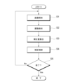
- FIG. 10 is a flowchart showing the steps of the image projection method according to this embodiment.
- a near image (second image) is displayed in the near display area 12B of the image irradiation unit 10B, and a far image (first image) is displayed in the far display area 13B. They are irradiated as the second image light and the first image light.
- the irradiation of the first image light and the second image light and the formation of the virtual image are the same as those described above.
- the process proceeds to step S2.
- vibration of the vehicle is detected by the vibration detection unit 50B, vibration information is acquired, and the acquired vibration information is sent to the correction control unit 60B.
- the vibration detection unit 50B is an acceleration sensor
- the acceleration information detected by the acceleration sensor is sent to the correction control unit 60B as vibration information.
- the acceleration information detected by the acceleration sensor is integrated within a predetermined period to calculate the amount of change in velocity and position, and the amount of change in position is sent to the correction control section 60B as vibration information.
- the process proceeds to step S3.
- the correction control section 60B generates a control signal for the optical driving section 70B based on the acquired vibration information.
- the vibration information is acceleration information
- the amount of change in velocity and position is calculated by integration within a predetermined period, and the amount of change in position is converted into the amount of change in the angle of incidence on the windshield.
- the rotation angle of the optical path in the first optical section 30B is calculated from the amount of change in the angle of incidence on the windshield, and a control signal is generated to change the optical path of the first optical section 30B in the opposite direction of the rotation angle. do.
- the correction control section 60B sends the control signal to the optical driving section 70B, and the process proceeds to step S4.
- step S4 based on the control signal generated in the correction amount calculation process, the optical driving section 70B is driven to change the optical path of the first optical section 30B.
- the optical driving section 70B is provided in the light branching section 20B, the incident angle to the free curved surface mirror 41 is changed by rotating the light branching section 20B.
- the imaging position of the virtual image is controlled in the direction opposite to the vibration of the vehicle, and the positional deviation from the background caused by the vibration of the vehicle is offset, thereby improving the visibility.
- the process proceeds to step S5.
- step S5 in the termination determination process, it is determined whether the image irradiation method is terminated. If not terminated, the process proceeds to step S1 to continue feedback control of vibration correction. When finished, exit from the loop of the feedback control and finish the control.
- the correction amount calculation process and the correction control process are described as separate processes, but the correction amount calculation may also be performed in the correction control process.
- the first optical unit 30B is controlled based on vibration information to correct the imaging position of the first image. Since fluctuations in the imaging position due to vibration are optically corrected by feedback control, there is no need to provide a margin area within the entire display area 11B as shown in FIG. Therefore, it is possible to secure an effective image display area, increase the areas of the near display area 12B and the far display area 13B, and project large first and second images. As a result, it is possible to improve the visibility of the image by suppressing the fluctuation of the imaging position due to the vibration of the vehicle.
- a distant image is emitted as the first image light and a near image is emitted as the second image light
- the two image lights may be imaged at a distant position as a distant image.
- the distance from the driver's viewpoint position to the imaging position is long, and the deviation from the background tends to increase due to blurring of the imaging position due to vibration. Therefore, by forming an image of the first image light at a long distance as a distant image and correcting the image forming position based on the vibration information, it is possible to enhance the effect of suppressing the positional deviation from the background and improving the visibility. can.
- the light branching unit 20 When the light branching unit 20 is a prism, it facilitates alignment and optical design when partially covering the image irradiation unit 10B and branching a part of the light. In addition, compared to the case where light is branched using a reflecting mirror, the volume to be secured for branching light can be reduced, and the size of the device can be reduced. Since the prism is smaller and lighter than the reflecting mirror 31B, the free-form surface mirror 32, the free-form surface mirror 41, etc., the torque when the optical drive unit 70B rotates is reduced, and the optical drive unit 70B can be made low-power and compact. can be improved. Since the prism is small and lightweight, it is possible to improve the accuracy of the rotating operation and increase the rotation speed during correction.
- the amount of correction of the incident angle of the first image light with respect to the windshield (display unit) is calculated based on the vibration information, and the optical image is projected according to the amount of correction.
- the imaging position of the first image is corrected by controlling the driving section 70B.
- FIG. 11 is a schematic diagram showing the configuration of an image projection device 110B according to this embodiment.
- the image projection device 110B includes an image irradiation unit 10B, light branching units 20aB and 20bB, a reflecting mirror 31B, a free-form surface mirror 32, a free-form surface mirror 41, a vibration detection unit 50B, and a correction unit 50B.
- a control section 60B, optical driving sections 70aB and 70bB, and an external light cut filter 80 are provided.
- the present embodiment differs from the first embodiment in that optical branching units 20aB and 20bB and optical driving units 70aB and 70bB are provided, and both the first optical unit 30B and the second optical unit 40B perform vibration correction. .
- the light branching section 20aB is arranged at a position overlapping the distant display area 13B, and the first image light from the distant display area 13B is branched toward the free-form surface mirror 41.
- the optical splitter 20aB corresponds to the first optical splitter in the present disclosure.
- a light splitter 20bB is arranged at a position overlapping the near display area 12B to split the second image light from the near display area 12B in the direction of the reflecting mirror 31B.
- the optical splitter 20bB corresponds to the second optical splitter in the present disclosure.
- the first image displayed in the distant display area 13B is projected onto the driver's viewpoint via the light branching section 20aB, the free-form surface mirror 41, the free-form surface mirror 32, the external light cut filter 80, and the windshield. reach.
- the second image displayed in the near display area 12B reaches the driver's viewpoint via the light splitter 20bB, the reflecting mirror 31B, the free-form surface mirror 32, the external light cut filter 80, and the windshield.
- the optical driving units 70aB and 70bB are provided in the light branching units 20aB and 20bB, respectively, and change the angle relative to the image irradiation unit 10B, and correspond to the first optical driving unit and the second optical driving unit in the present disclosure, respectively. are doing.
- the vibration detection unit 50B and the correction control unit 60B detect the vibration of the vehicle and individually control the optical drive units 70aB and 70bB based on the vibration information to detect the imaging positions of the first image and the second image due to the vibration. to compensate for variations in
- the correction amount of the incident angle of the first image light and the second image light with respect to the windshield (display unit) is calculated based on the vibration information, and the correction amount is calculated according to the correction amount.
- the imaging positions of the first image and the second image are corrected by controlling the optical drive units 70aB and 70bB. As a result, it is possible to improve the visibility of the image by suppressing the fluctuation of the imaging position due to the vibration of the vehicle while securing an effective image display area.
- the light splitting unit 20B is used to split the light emitted from the image irradiating unit 10B, and the far image and the near image are projected at different distances to form virtual images.
- one image may be displayed by the image irradiation unit 10B, and one virtual image may be formed by the first optical unit 30B without using the light branching unit 20B and the second optical unit 40B.
- the optical drive section 70B may be provided in the free-form surface mirror 41 to change the relative angle of the free-form surface mirror 41 with respect to the image irradiation section 10B.
- the control of the optical drive unit 70B is the same as that of the fourth embodiment.
- a control signal for controlling the drive of the section 70B is generated.
- the correction amount of the incident angle of the first image light with respect to the windshield (display unit) is calculated based on the vibration information, and the optical drive unit 70B is operated according to the correction amount. control to correct the imaging positions of the first image and the second image. As a result, it is possible to improve the visibility of the image by suppressing the fluctuation of the imaging position due to the vibration of the vehicle while securing an effective image display area.
Landscapes
- Physics & Mathematics (AREA)
- Engineering & Computer Science (AREA)
- General Physics & Mathematics (AREA)
- Optics & Photonics (AREA)
- Chemical & Material Sciences (AREA)
- Combustion & Propulsion (AREA)
- Transportation (AREA)
- Mechanical Engineering (AREA)
- Instrument Panels (AREA)
Abstract
Description
以下、本開示の実施形態について、図面を参照して詳細に説明する。各図面に示される同一または同等の構成要素、部材、処理には、同一の符号を付すものとし、適宜重複した説明は省略する。図1は、本実施形態に係る画像投影装置100の構成を示す模式図である。図1に示すように画像投影装置100は、画像照射部10と、光分岐部20と、反射鏡31と、自由曲面ミラー32と、自由曲面ミラー33と、直接表示部40と、外光カットフィルタ50を備えており、ウィンドシールド(表示部)60を介して虚像70を投影する。画像投影装置100は、各部と情報通信可能に接続されて、各部を制御する制御部を備えている(図示省略)。制御部の構成は限定されないが、一例として情報処理を行うためのCPU(Central Processing Unit)や、メモリ装置、記録媒体、情報通信装置等を備えるものが挙げられる。制御部は、予め定められたプログラムに従って各部の動作を制御し、画像を含んだ情報(画像情報)を画像照射部10に送出する。
次に、本開示の第2実施形態について図4を用いて説明する。第1実施形態と重複する内容は説明を省略する。図4は、本実施形態に係る画像投影装置110の構成を示す模式図である。本実施形態は、光分岐部20が第1光学部に含まれる点が第1実施形態と異なっている。
次に、本開示の第3実施形態について図5を用いて説明する。第1実施形態と重複する内容は説明を省略する。図5は、本実施形態に係る画像投影装置120の構成を示す模式図である。本実施形態の画像投影装置120は、光分岐部20を複数備えている点が第1実施形態と異なっている。
次に、本開示の第4実施形態について図7を用いて説明する。第1実施形態と重複する内容は説明を省略する。図7は、本実施形態に係る画像投影装置100Bの構成を示すブロック図である。図7に示すように画像投影装置100Bは、画像照射部10Bと、光分岐部20Bと、第1光学部30Bと、第2光学部40Bと、振動検知部50Bと、補正制御部60Bと、光学駆動部70Bを備えている。画像投影装置100Bから投影された光は図示を省略するウィンドシールド(表示部)を介して運転者の視点位置に照射される。
次に、本開示の第5実施形態について図11を用いて説明する。第4実施形態と重複する内容は説明を省略する。図11は、本実施形態に係る画像投影装置110Bの構成を示す模式図である。図11に示すように画像投影装置110Bは、画像照射部10Bと、光分岐部20aB,20bBと、反射鏡31Bと、自由曲面ミラー32と、自由曲面ミラー41と、振動検知部50Bと、補正制御部60Bと、光学駆動部70aB,70bBと、外光カットフィルタ80とを備えている。本実施形態では、光分岐部20aB,20bBおよび光学駆動部70aB,70bBを設けて、第1光学部30Bおよび第2光学部40Bのどちらも振動補正を行う点が第1実施形態と異なっている。
次に、本開示の第6実施形態について説明する。第4実施形態と重複する内容は説明を省略する。第4実施形態および第5実施形態では、光分岐部20Bを用いて画像照射部10Bから照射される光を分岐して、遠方画像および近方画像として異なる距離に投影して虚像を結像していた。しかし、画像照射部10Bで表示する画像を一つとして、光分岐部20Bと第2光学部40Bを用いずに第1光学部30Bで一つの虚像を結像してもよい。この場合には、光学駆動部70Bが、自由曲面ミラー41に設けられて、自由曲面ミラー41の画像照射部10Bに対する相対的な角度を変更してもよい。このとき、光学駆動部70Bの制御は第4実施形態と同様であり、振動検知部50Bで車両の振動情報を取得し、振動情報に基づいて補正制御部60Bで補正量を算出し、光学駆動部70Bの駆動を制御する制御信号を生成する。
Claims (17)
- 虚像を表示する表示部に対して投影画像を照射する画像投影装置であって、
画像を照射する画像照射部と、
前記画像を照射する光を少なくとも第1画像光と第2画像光に分岐する光分岐部と、
前記表示部を介して前記第1画像光を前記投影画像として視点方向に照射する第1光学部と、
前記表示部を介さずに前記第2画像光を前記視点方向に照射する第2光学部とを備える画像投影装置。 - 請求項1に記載の画像投影装置であって、
前記光分岐部は、前記画像照射部から照射される光の一部の経路上に配置されたプリズムを備える画像投影装置。 - 請求項2に記載の画像投影装置であって、
前記プリズムは、前記第2光学部の一部である画像投影装置。 - 請求項2に記載の画像投影装置であって、
前記プリズムは、前記第1光学部の一部である画像投影装置。 - 請求項4に記載の画像投影装置であって、
前記プリズムは、赤外光吸収材料を含有する画像投影装置。 - 請求項1から5の何れか一項に記載の画像投影装置であって、
前記第2光学部は、前記第2画像光を円偏光に変換する位相差フィルムを備える画像投影装置。 - 請求項1から5の何れか一項に記載の画像投影装置であって、
前記第2光学部は、背面に前記第2画像光が照射される透過型スクリーンを備える画像投影装置。 - 請求項1から5の何れか一項に記載の画像投影装置であって、
前記第2光学部は、前記第2画像光を拡大して照射する拡大光学部を含む画像投影装置。 - 虚像を表示する表示部に対して投影画像を照射する画像投影装置であって、
第1画像を照射する画像照射部と、
前記表示部を介して前記第1画像を第1画像光として視点方向に照射する第1光学部と、
振動情報に基づいて前記表示部に対する前記第1画像光の入射角度を変更する第1光学駆動部とを備える画像投影装置。 - 請求項9に記載の画像投影装置であって、
振動を検知し前記振動情報を取得する振動検知部と、
前記振動情報に基づいて前記入射角度の補正量を算出し、前記補正量に応じて前記第1光学駆動部を制御して、前記第1画像の結像位置を補正する補正制御部とを備える画像投影装置。 - 請求項9または10に記載の画像投影装置であって、
前記画像照射部はさらに第2画像を照射し、
前記表示部を介して前記第2画像を第2画像光として視点方向に照射する第2光学部を備える画像投影装置。 - 請求項11に記載の画像投影装置であって、
前記虚像の結像位置は、前記第1画像のほうが前記第2画像よりも視点位置から遠い画像投影装置。 - 請求項11に記載の画像投影装置であって、
前記第1画像光と前記第2画像光を分岐する光分岐部を備え、
前記第1光学駆動部は、前記画像照射部に対する前記光分岐部の角度を変更する画像投影装置。 - 請求項13に記載の画像投影装置であって、
前記光分岐部はプリズムである画像投影装置。 - 請求項11に記載の画像投影装置であって、
前記振動情報に基づいて前記表示部に対する前記第2画像光の入射角度を変更する第2光学駆動部を備える画像投影装置。 - 請求項9に記載の画像投影装置であって、
前記第1光学駆動部は、前記第1光学部を構成する光学部材の何れかの角度を変更する画像投影装置。 - 虚像を表示する表示部に対して投影画像を照射する画像投影方法であって、
前記表示部を介して第1画像を第1画像光として視点方向に照射し、
振動情報を取得し、
前記振動情報に基づいて、前記表示部に対する前記第1画像光の入射角度を変更して、前記第1画像の結像位置を補正することを備える画像投影方法。
Priority Applications (3)
| Application Number | Priority Date | Filing Date | Title |
|---|---|---|---|
| EP22878359.3A EP4414770A4 (en) | 2021-10-05 | 2022-09-26 | IMAGE PROJECTION DEVICE AND IMAGE PROJECTION METHOD |
| CN202280067186.5A CN118056154A (zh) | 2021-10-05 | 2022-09-26 | 图像投影装置以及图像投影方法 |
| US18/698,967 US20240427145A1 (en) | 2021-10-05 | 2022-09-26 | Image projecting device and image projecting method |
Applications Claiming Priority (4)
| Application Number | Priority Date | Filing Date | Title |
|---|---|---|---|
| JP2021164153A JP7712170B2 (ja) | 2021-10-05 | 2021-10-05 | 画像投影装置 |
| JP2021-164153 | 2021-10-05 | ||
| JP2021175994A JP7712179B2 (ja) | 2021-10-27 | 2021-10-27 | 画像投影装置および画像投影方法 |
| JP2021-175994 | 2021-10-27 |
Publications (1)
| Publication Number | Publication Date |
|---|---|
| WO2023058488A1 true WO2023058488A1 (ja) | 2023-04-13 |
Family
ID=85804247
Family Applications (1)
| Application Number | Title | Priority Date | Filing Date |
|---|---|---|---|
| PCT/JP2022/035716 Ceased WO2023058488A1 (ja) | 2021-10-05 | 2022-09-26 | 画像投影装置および画像投影方法 |
Country Status (3)
| Country | Link |
|---|---|
| US (1) | US20240427145A1 (ja) |
| EP (1) | EP4414770A4 (ja) |
| WO (1) | WO2023058488A1 (ja) |
Cited By (1)
| Publication number | Priority date | Publication date | Assignee | Title |
|---|---|---|---|---|
| WO2025075363A1 (ko) * | 2023-10-06 | 2025-04-10 | 엘지전자 주식회사 | 차량 디스플레이 장치 및 그것의 동작방법 |
Citations (13)
| Publication number | Priority date | Publication date | Assignee | Title |
|---|---|---|---|---|
| JP2002196276A (ja) * | 2000-12-25 | 2002-07-12 | Minolta Co Ltd | 車両用表示装置 |
| JP2004133181A (ja) * | 2002-10-10 | 2004-04-30 | Nippon Soken Inc | 車両用分割表示装置 |
| JP2010004511A (ja) * | 2008-05-07 | 2010-01-07 | Minoru Inaba | 立体映像撮像表示システム |
| JP2016173583A (ja) * | 2016-04-28 | 2016-09-29 | 日本精機株式会社 | 投影装置及びヘッドアップディスプレイ装置 |
| KR20180003155A (ko) * | 2016-06-30 | 2018-01-09 | 세종공업 주식회사 | 떨림 보정 기능을 갖는 헤드업 디스플레이 장치 및 헤드업 디스플레이의 영상 보정방법 |
| JP2019034610A (ja) * | 2017-08-11 | 2019-03-07 | アルパイン株式会社 | 車載システム及びヘッドアップディスプレイ装置 |
| JP2019119262A (ja) | 2017-12-28 | 2019-07-22 | 株式会社小糸製作所 | ヘッドアップディスプレイ装置 |
| JP2019119248A (ja) | 2017-12-28 | 2019-07-22 | 株式会社小糸製作所 | ヘッドアップディスプレイ装置 |
| WO2020084954A1 (ja) * | 2018-10-23 | 2020-04-30 | マクセル株式会社 | ヘッドアップディスプレイシステム |
| WO2021045185A1 (ja) * | 2019-09-06 | 2021-03-11 | パナソニックIpマネジメント株式会社 | 遮熱フィルム |
| JP2021067909A (ja) * | 2019-10-28 | 2021-04-30 | 日本精機株式会社 | 立体表示装置及びヘッドアップディスプレイ装置 |
| JP2021164153A (ja) | 2020-04-01 | 2021-10-11 | シャープ株式会社 | 固体撮像素子 |
| JP2021175994A (ja) | 2020-05-01 | 2021-11-04 | 株式会社フジクラ | 光コネクタシステム及びプラグ |
Family Cites Families (2)
| Publication number | Priority date | Publication date | Assignee | Title |
|---|---|---|---|---|
| IT1246064B (it) * | 1991-04-24 | 1994-11-07 | Veglia Borletti Srl | Apparato per la visualizzazione di dati in un veicolo |
| CN111751994B (zh) * | 2019-08-02 | 2022-11-15 | 友达光电股份有限公司 | 显示装置以及车辆 |
-
2022
- 2022-09-26 US US18/698,967 patent/US20240427145A1/en active Pending
- 2022-09-26 EP EP22878359.3A patent/EP4414770A4/en not_active Withdrawn
- 2022-09-26 WO PCT/JP2022/035716 patent/WO2023058488A1/ja not_active Ceased
Patent Citations (13)
| Publication number | Priority date | Publication date | Assignee | Title |
|---|---|---|---|---|
| JP2002196276A (ja) * | 2000-12-25 | 2002-07-12 | Minolta Co Ltd | 車両用表示装置 |
| JP2004133181A (ja) * | 2002-10-10 | 2004-04-30 | Nippon Soken Inc | 車両用分割表示装置 |
| JP2010004511A (ja) * | 2008-05-07 | 2010-01-07 | Minoru Inaba | 立体映像撮像表示システム |
| JP2016173583A (ja) * | 2016-04-28 | 2016-09-29 | 日本精機株式会社 | 投影装置及びヘッドアップディスプレイ装置 |
| KR20180003155A (ko) * | 2016-06-30 | 2018-01-09 | 세종공업 주식회사 | 떨림 보정 기능을 갖는 헤드업 디스플레이 장치 및 헤드업 디스플레이의 영상 보정방법 |
| JP2019034610A (ja) * | 2017-08-11 | 2019-03-07 | アルパイン株式会社 | 車載システム及びヘッドアップディスプレイ装置 |
| JP2019119262A (ja) | 2017-12-28 | 2019-07-22 | 株式会社小糸製作所 | ヘッドアップディスプレイ装置 |
| JP2019119248A (ja) | 2017-12-28 | 2019-07-22 | 株式会社小糸製作所 | ヘッドアップディスプレイ装置 |
| WO2020084954A1 (ja) * | 2018-10-23 | 2020-04-30 | マクセル株式会社 | ヘッドアップディスプレイシステム |
| WO2021045185A1 (ja) * | 2019-09-06 | 2021-03-11 | パナソニックIpマネジメント株式会社 | 遮熱フィルム |
| JP2021067909A (ja) * | 2019-10-28 | 2021-04-30 | 日本精機株式会社 | 立体表示装置及びヘッドアップディスプレイ装置 |
| JP2021164153A (ja) | 2020-04-01 | 2021-10-11 | シャープ株式会社 | 固体撮像素子 |
| JP2021175994A (ja) | 2020-05-01 | 2021-11-04 | 株式会社フジクラ | 光コネクタシステム及びプラグ |
Non-Patent Citations (1)
| Title |
|---|
| See also references of EP4414770A4 |
Cited By (1)
| Publication number | Priority date | Publication date | Assignee | Title |
|---|---|---|---|---|
| WO2025075363A1 (ko) * | 2023-10-06 | 2025-04-10 | 엘지전자 주식회사 | 차량 디스플레이 장치 및 그것의 동작방법 |
Also Published As
| Publication number | Publication date |
|---|---|
| EP4414770A1 (en) | 2024-08-14 |
| US20240427145A1 (en) | 2024-12-26 |
| EP4414770A4 (en) | 2025-03-19 |
Similar Documents
| Publication | Publication Date | Title |
|---|---|---|
| JP5741251B2 (ja) | 虚像表示装置 | |
| US11360303B2 (en) | Head up display system and display method of head up display system | |
| US11970060B2 (en) | Head-up display and means of transportation comprising a head-up display | |
| KR20170008430A (ko) | 헤드 업 디스플레이 장치 | |
| JP7600020B2 (ja) | 画像投影装置 | |
| WO2023058488A1 (ja) | 画像投影装置および画像投影方法 | |
| WO2023176897A1 (ja) | 画像投影装置、および画像投影方法 | |
| JP7712179B2 (ja) | 画像投影装置および画像投影方法 | |
| US12033287B2 (en) | Vehicle head-up display device and method | |
| CN113970845A (zh) | 多焦平面抬头显示设备 | |
| JP6593393B2 (ja) | 虚像表示装置 | |
| JP7712170B2 (ja) | 画像投影装置 | |
| KR20100044526A (ko) | 차량용 헤드 업 디스플레이 장치 | |
| US11993147B2 (en) | Head-up display apparatus | |
| JP7795400B2 (ja) | 画像投影装置 | |
| EP4664185A1 (en) | Image projection device | |
| JP2024047482A (ja) | 画像投影装置 | |
| JP2025183629A (ja) | 画像投影装置 | |
| JP2025022146A (ja) | 画像投影装置 | |
| JP2024128896A (ja) | 画像投影装置 | |
| JP6593494B1 (ja) | 虚像表示装置 | |
| JP2024128895A (ja) | 画像投影装置 | |
| KR20230072128A (ko) | 차량용 헤드업 디스플레이 장치 및 방법 | |
| JP2025075870A (ja) | 画像投影装置 | |
| JP2025040849A (ja) | 画像投影装置 |
Legal Events
| Date | Code | Title | Description |
|---|---|---|---|
| 121 | Ep: the epo has been informed by wipo that ep was designated in this application |
Ref document number: 22878359 Country of ref document: EP Kind code of ref document: A1 |
|
| WWE | Wipo information: entry into national phase |
Ref document number: 202280067186.5 Country of ref document: CN |
|
| WWE | Wipo information: entry into national phase |
Ref document number: 18698967 Country of ref document: US |
|
| WWE | Wipo information: entry into national phase |
Ref document number: 2022878359 Country of ref document: EP |
|
| NENP | Non-entry into the national phase |
Ref country code: DE |
|
| ENP | Entry into the national phase |
Ref document number: 2022878359 Country of ref document: EP Effective date: 20240506 |
|
| WWW | Wipo information: withdrawn in national office |
Ref document number: 2022878359 Country of ref document: EP |