WO2023058568A1 - トルク検出装置 - Google Patents
トルク検出装置 Download PDFInfo
- Publication number
- WO2023058568A1 WO2023058568A1 PCT/JP2022/036688 JP2022036688W WO2023058568A1 WO 2023058568 A1 WO2023058568 A1 WO 2023058568A1 JP 2022036688 W JP2022036688 W JP 2022036688W WO 2023058568 A1 WO2023058568 A1 WO 2023058568A1
- Authority
- WO
- WIPO (PCT)
- Prior art keywords
- axial direction
- yoke
- torque
- rotating body
- magnetic
- Prior art date
- Legal status (The legal status is an assumption and is not a legal conclusion. Google has not performed a legal analysis and makes no representation as to the accuracy of the status listed.)
- Ceased
Links
Images



















Classifications
-
- B—PERFORMING OPERATIONS; TRANSPORTING
- B62—LAND VEHICLES FOR TRAVELLING OTHERWISE THAN ON RAILS
- B62D—MOTOR VEHICLES; TRAILERS
- B62D6/00—Arrangements for automatically controlling steering depending on driving conditions sensed and responded to, e.g. control circuits
- B62D6/08—Arrangements for automatically controlling steering depending on driving conditions sensed and responded to, e.g. control circuits responsive only to driver input torque
- B62D6/10—Arrangements for automatically controlling steering depending on driving conditions sensed and responded to, e.g. control circuits responsive only to driver input torque characterised by means for sensing or determining torque
-
- G—PHYSICS
- G01—MEASURING; TESTING
- G01L—MEASURING FORCE, STRESS, TORQUE, WORK, MECHANICAL POWER, MECHANICAL EFFICIENCY, OR FLUID PRESSURE
- G01L3/00—Measuring torque, work, mechanical power, or mechanical efficiency, in general
- G01L3/02—Rotary-transmission dynamometers
- G01L3/04—Rotary-transmission dynamometers wherein the torque-transmitting element comprises a torsionally-flexible shaft
- G01L3/10—Rotary-transmission dynamometers wherein the torque-transmitting element comprises a torsionally-flexible shaft involving electric or magnetic means for indicating
-
- G—PHYSICS
- G01—MEASURING; TESTING
- G01L—MEASURING FORCE, STRESS, TORQUE, WORK, MECHANICAL POWER, MECHANICAL EFFICIENCY, OR FLUID PRESSURE
- G01L3/00—Measuring torque, work, mechanical power, or mechanical efficiency, in general
- G01L3/02—Rotary-transmission dynamometers
- G01L3/04—Rotary-transmission dynamometers wherein the torque-transmitting element comprises a torsionally-flexible shaft
- G01L3/10—Rotary-transmission dynamometers wherein the torque-transmitting element comprises a torsionally-flexible shaft involving electric or magnetic means for indicating
- G01L3/101—Rotary-transmission dynamometers wherein the torque-transmitting element comprises a torsionally-flexible shaft involving electric or magnetic means for indicating involving magnetic or electromagnetic means
-
- G—PHYSICS
- G01—MEASURING; TESTING
- G01L—MEASURING FORCE, STRESS, TORQUE, WORK, MECHANICAL POWER, MECHANICAL EFFICIENCY, OR FLUID PRESSURE
- G01L3/00—Measuring torque, work, mechanical power, or mechanical efficiency, in general
- G01L3/02—Rotary-transmission dynamometers
- G01L3/04—Rotary-transmission dynamometers wherein the torque-transmitting element comprises a torsionally-flexible shaft
- G01L3/10—Rotary-transmission dynamometers wherein the torque-transmitting element comprises a torsionally-flexible shaft involving electric or magnetic means for indicating
- G01L3/101—Rotary-transmission dynamometers wherein the torque-transmitting element comprises a torsionally-flexible shaft involving electric or magnetic means for indicating involving magnetic or electromagnetic means
- G01L3/104—Rotary-transmission dynamometers wherein the torque-transmitting element comprises a torsionally-flexible shaft involving electric or magnetic means for indicating involving magnetic or electromagnetic means involving permanent magnets
-
- G—PHYSICS
- G01—MEASURING; TESTING
- G01L—MEASURING FORCE, STRESS, TORQUE, WORK, MECHANICAL POWER, MECHANICAL EFFICIENCY, OR FLUID PRESSURE
- G01L5/00—Apparatus for, or methods of, measuring force, work, mechanical power, or torque, specially adapted for specific purposes
- G01L5/22—Apparatus for, or methods of, measuring force, work, mechanical power, or torque, specially adapted for specific purposes for measuring the force applied to control members, e.g. control members of vehicles, triggers
- G01L5/221—Apparatus for, or methods of, measuring force, work, mechanical power, or torque, specially adapted for specific purposes for measuring the force applied to control members, e.g. control members of vehicles, triggers to steering wheels, e.g. for power assisted steering
Definitions
- the present disclosure relates to a torque detection device.
- a sensor device for detecting torque applied to a steering shaft connected to a steering wheel of a vehicle includes a magnet, a magnetic yoke, a sensor module, a sensor housing and a steering gear housing.
- a magnetic yoke changes the magnetic field generated by the magnet.
- the sensor module detects the torque applied to the steering wheel by detecting the strength of the magnetic field changed by the magnetic yoke.
- the sensor housing accommodates the sensor module.
- the sensor housing containing this sensor module is inserted into the steering gear housing in a direction orthogonal to the axis of the steering shaft.
- the sensor housing and the magnetic yoke are accommodated in the steering gear housing by inserting the magnetic yoke into the steering gear housing in the axial direction of the steering shaft. Therefore, when manufacturing this sensor device, the parts are inserted in two directions, one perpendicular to the axis of the steering shaft and the other in the axial direction of the steering shaft, which complicates the manufacturing process.
- An object of the present disclosure is to provide a torque sensing device that simplifies the manufacturing process.
- a torque detection device for detecting torque generated in an object to be detected comprises: a magnet that generates a magnetic field and rotates together with the object to be detected; An annular rotating body that rotates, an annular annular part that rotates together with the rotating body, and an annular part that protrudes from the annular part in the axial direction so that it rotates together with the annular part while facing the magnet in a direction perpendicular to the axial direction.
- a yoke that changes the magnetic field generated by the magnet, a magnetic detection unit that detects the strength of the magnetic field that corresponds to the torque and changes due to the rotation of the claw, and a magnetic detection unit.
- a sensor cover portion connected to the surface of the sensor case facing the axial direction; a rotating body cover portion connected to the sensor cover portion and into which the rotating body is inserted in the axial direction; and the rotating body cover portion is a torque detecting device that regulates relative movement of the rotating body with respect to the sensor case in a direction orthogonal to the axial direction.
- a torque detection device for detecting torque generated in an object to be detected, wherein the magnet rotates together with the object to be detected while generating a magnetic field, and the axis extending in the axial direction is detected as a center.
- An annular rotating body that rotates together with the object, an annular annular part that rotates together with the rotating body, and an annular part that protrudes from the annular part in the axial direction so that it rotates together with the annular part while facing the magnet in a direction perpendicular to the axial direction.
- a yoke that changes the magnetic field generated by the magnet by doing so; a magnetism detector that corresponds to the torque and detects the strength of the magnetic field that changes as the claw rotates; a magnetism detector and a holding member that restricts relative movement of the rotating body with respect to the sensor case in the direction perpendicular to the axial direction by surrounding the rotating body with the sensor case in the direction perpendicular to the axial direction. It is a torque detection device provided.
- a torque detection device for detecting torque generated in a detection target, wherein the magnet rotates together with the detection target while generating a magnetic field, and the axis extending in the axial direction is detected as the center.
- An annular rotating body that rotates together with the object, an annular annular part that rotates together with the rotating body, and an annular part that protrudes from the annular part in the axial direction so that it rotates together with the annular part while facing the magnet in a direction perpendicular to the axial direction.
- a yoke that changes the magnetic field generated by the magnet by rotating the yoke; and a magnetism detection unit that detects the strength of the magnetic field that corresponds to the torque and changes as the claw rotates.
- a sensor case having a regulating portion into which the rotating body is inserted in the axial direction, and an accommodating portion connected to the regulating portion and accommodating the magnetic detecting portion, the regulating portion is a torque detection device that regulates the relative movement of the rotating body with respect to the sensor case in the direction orthogonal to the axial direction.
- FIG. 1 is a configuration diagram of a steering system in which the torque detection device of the first embodiment is used;
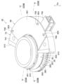
- FIG. 1 is an exploded perspective view of part of a steering system;
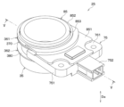
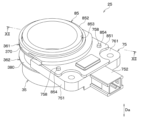
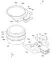
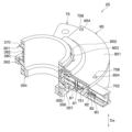
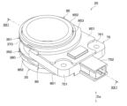
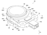
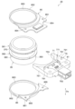
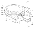
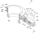
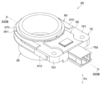
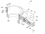
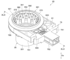
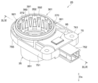
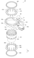
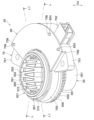
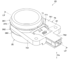
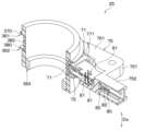
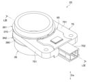
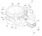
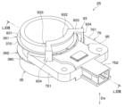
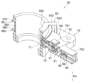
- FIG. 1 is a perspective view of a torque detection device;
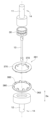
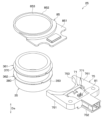
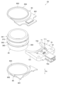
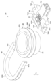
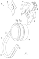
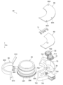
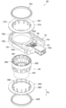
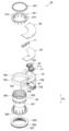
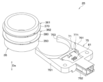
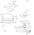
- FIG. 2 is an exploded perspective view of the torque detection device;
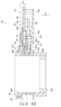
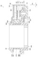
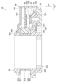
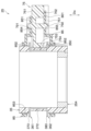
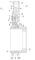
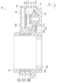
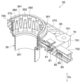
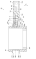
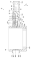
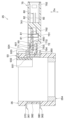
- FIG. 4 is a cross-sectional view taken along the line VV of FIG. 3;
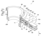
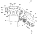
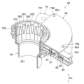
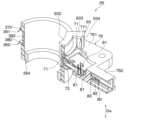
- FIG. 2 is a perspective cross-sectional view of the torque detection device;
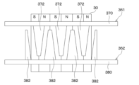
- FIG. 4 is a side view showing the neutral state of the magnet of the torque sensor, the first yoke, and the second yoke;
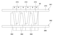
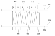
- FIG. 4 is a side view of the magnet, first yoke and second yoke of the torque sensor when the steering wheel of the steering system is rotated;
- FIG. 1 is an exploded perspective view of part of a steering system;
- FIG. 1 is a perspective view of a torque detection device;
- FIG. 2 is an exploded perspective view of the torque detection device;
- FIG. 4 is a side view of the magnet, first yoke, and second yoke of the torque sensor when the steering wheel is rotated;
- FIG. 2 is an exploded perspective view of the torque detection device; XII-XII line sectional view of FIG.
- FIG. 2 is a perspective cross-sectional view of the torque detection device;
- FIG. 2 is an exploded perspective view of the torque detection device;
- FIG. 14 is a cross-sectional view taken along line XVI-XVI. Sectional view taken along line XVII-XVII of FIG. FIG.
- FIG. 2 is a perspective cross-sectional view of the torque detection device; The perspective view of the torque detection apparatus of 4th Embodiment.
- FIG. 2 is an exploded perspective view of the torque detection device; XXI-XXI line sectional view of FIG.
- FIG. 2 is a perspective cross-sectional view of the torque detection device;
- FIG. 2 is an exploded perspective view of the torque detection device; XXV-XXV line sectional view of FIG.
- FIG. 2 is a perspective cross-sectional view of the torque detection device;
- FIG. 2 is an exploded perspective view of the torque detection device; XXIX-XXIX line sectional view of FIG.
- FIG. 2 is a perspective cross-sectional view of the torque detection device; The perspective view of the torque detection apparatus of 7th Embodiment.
- FIG. 2 is an exploded perspective view of the torque detection device; XXXIII-XXXIII line sectional view of FIG.
- FIG. 2 is a perspective cross-sectional view of the torque detection device; The perspective view of the torque detection apparatus of 8th Embodiment.
- FIG. 2 is an exploded perspective view of the torque detection device; XXVII-XXXVII line sectional view of FIG. XXXVIII-XXXVIII line sectional view of FIG.
- FIG. 2 is a perspective cross-sectional view of the torque detection device; The perspective view of the torque detection apparatus of 9th Embodiment.
- FIG. 1 The perspective view of the torque detection apparatus of 9th Embodiment.
- FIG. 2 is an exploded perspective view of the torque detection device; XLII-XLII line sectional view of FIG. FIG. 2 is a perspective cross-sectional view of the torque detection device; The perspective view of the torque detection apparatus of 10th Embodiment.
- FIG. 2 is an exploded perspective view of the torque detection device; XLVI-XLVI line sectional view of FIG. FIG. 2 is a perspective cross-sectional view of the torque detection device; The perspective view of the torque detection apparatus of 11th Embodiment.
- FIG. 2 is an exploded perspective view of the torque detection device;
- FIG. 48 is a cross-sectional view along the LL line.
- LI-LI line sectional view of FIG. FIG. 2 is a perspective cross-sectional view of the torque detection device; FIG.
- FIG. 21 is a perspective view of a torque detection device according to a twelfth embodiment;
- FIG. 2 is an exploded perspective view of the torque detection device;
- FIG. 53 is a cross-sectional view along the LV-LV line;
- FIG. 2 is a perspective cross-sectional view of the torque detection device;
- FIG. 21 is a perspective view of a torque detection device according to a thirteenth embodiment;
- FIG. 2 is an exploded perspective view of the torque detection device;
- FIG. 57 is a cross-sectional view along the LIX-LIX line.
- FIG. 2 is a perspective cross-sectional view of the torque detection device;
- FIG. 21 is a perspective view of a torque detection device according to a fourteenth embodiment;
- FIG. 2 is an exploded perspective view of the torque detection device;
- FIG. 2 is a perspective cross-sectional view of the torque detection device;
- FIG. 21 is a perspective view of a torque detection device according to a fifteenth embodiment;
- FIG. 2 is an exploded perspective view of the torque detection device;
- FIG. 2 is a perspective cross-sectional view of the torque detection device;
- the torque detection device of this embodiment is used, for example, in a steering system 1 mounted on a vehicle. First, the steering system 1 will be described.
- the steering system 1 assists steering for changing the direction of the wheels 17.
- the steering system 1 includes a steering wheel 5, a first steering shaft 11, a torsion bar 13 and a second steering shaft 12, as shown in FIGS.
- the steering system 1 also includes a shaft pin 14 , a pinion gear 15 , a rack shaft 16 , wheels 17 , a torque sensor 25 , a motor controller 18 , a motor 19 and a reduction gear 20 .
- the steering wheel 5, as shown in FIG. 1, is rotated by being steered by the driver of the vehicle, automatic driving, or the like.
- the first steering shaft 11 is connected to the steering wheel 5. Therefore, the first steering shaft 11 rotates together with the steering wheel 5 .
- the torsion bar 13 is connected to the first steering shaft 11. Therefore, the torsion bar 13 rotates together with the steering wheel 5 and the first steering shaft 11 .
- the second steering shaft 12 is connected to the torsion bar 13. Therefore, the torsion bar 13 rotates together with the steering wheel 5 , the first steering shaft 11 and the torsion bar 13 .
- the shaft pin 14 is inserted into a hole formed in the first steering shaft 11 and a hole in the torsion bar 13 corresponding to the hole in the first steering shaft 11, as shown in FIG. Thereby, the first steering shaft 11 and the torsion bar 13 are fixed. Also, the shaft pin 14 is inserted into a hole formed in the second steering shaft 12 and a hole in the torsion bar 13 corresponding to the hole in the second steering shaft 12 . Thereby, the second steering shaft 12 and the torsion bar 13 are fixed.
- the pinion gear 15 is connected to the second steering shaft 12 as shown in FIG. Further, the pinion gear 15 meshes with a rack shaft 16, which will be described later. Furthermore, the pinion gear 15 converts the rotational motion of the second steering shaft 12 into linear motion of the rack shaft 16 .
- the rack shaft 16 is connected to wheels 17 via tie rods (not shown) or the like. Also, the rack shaft 16 changes the orientation of the wheels 17 by linearly moving.
- the torque sensor 25 corresponds to a torque detection device, and detects a signal corresponding to the torsion torque generated in the torsion bar 13 due to the rotation of the steering wheel 5 . Thereby, the torque sensor 25 detects the steering torque. Further, the torque sensor 25 outputs a signal corresponding to the detected steering torque to the motor control device 18, which will be described later. Details of the torque sensor 25 will be described later.
- the steering torque is the torque applied when the steering wheel 5 rotates.
- the motor control device 18 is mainly composed of a microcomputer and the like, and is equipped with a CPU, ROM, flash memory, RAM, I/O, drive circuits, and bus lines connecting these components.
- the motor control device 18 also executes programs stored in the ROM. Thereby, the motor control device 18 calculates the rotation angle of the motor 19, which will be described later. Furthermore, the motor control device 18 calculates the steering torque based on the signal corresponding to the steering torque from the torque sensor 25 . Further, the motor control device 18 controls the rotation of the motor 19, which will be described later, based on the calculated rotation angle of the motor 19, the steering torque, and the like.
- the motor 19 rotates based on the output from the motor control device 18. Thereby, the motor 19 generates torque.
- the reduction gear 20 is connected to the motor 19 and the second steering shaft 12.
- the reduction gear 20 also reduces the speed of rotation of the motor 19 and transmits the torque generated by the motor 19 to the second steering shaft 12 . This assists the steering for changing the direction of the wheels 17 .
- the steering system 1 is configured as described above. Next, the configuration of the torque sensor 25 will be described.
- the torque sensor 25 includes a magnet 30, a rotor 35, a first yoke 361, a second yoke 362 and a fixing collar 354, as shown in FIGS.
- the torque sensor 25 also includes a substrate 60 , a magnetic detection section 600 , a first magnetic induction member 71 , a second magnetic induction member 72 , a sensor case 75 , terminals 80 and a cover 85 .
- the magnet 30 is formed in an annular shape, as shown in FIG. Also, the magnet 30 is connected to the end of the first steering shaft 11 . Further, a part of the torsion bar 13 is inserted into the hole of the magnet 30. As shown in FIG. Also, the axis of the magnet 30 is coaxial with the axis of the torsion bar 13 . Therefore, the magnet 30 rotates around the axis of the torsion bar 13 together with the first steering shaft 11 . Furthermore, the magnet 30 is magnetized so that the magnetic poles are alternately reversed in the direction of rotation of the magnet 30 .
- the rotating body 35 is formed in a cylindrical shape, as shown in FIGS. Also, the axis of the rotating body 35 is coaxial with the axis of the magnet 30 . Therefore, the axis of the rotor 35, the axis of the magnet 30, and the axis of the torsion bar 13 are coaxial.
- the radial direction of the rotating body 35 is simply referred to as the radial direction for convenience.
- the axial direction Da of the rotor 35 is simply referred to as the axial direction Da.
- the circumferential direction around the axis of the rotor 35 is simply referred to as the circumferential direction.
- the first yoke 361 is made of a cylindrical soft magnetic material.
- the first yoke 361 also includes a first yoke annular portion 370 and a plurality of first yoke claw portions 372 .
- the first yoke annular portion 370 is formed in an annular shape. A part of the first yoke annular portion 370 is inserted into a hole of the rotor 35 extending in the radial direction.
- the first yoke claw portion 372 protrudes from the inner side of the first yoke annular portion 370 in the axial direction Da. Also, the first yoke claw portion 372 is formed in a tapered shape in which the width decreases from the inner side of the first yoke annular portion 370 toward the distal end side. Furthermore, the first yoke claw portion 372 is connected to the inner surface of the rotating body 35 . Also, the first yoke claw portion 372 faces the outer surface of the magnet 30 in the radial direction. Furthermore, since the holes of the rotor 35 are formed at predetermined intervals in the circumferential direction, the first yoke claw portions 372 are formed at predetermined intervals in the circumferential direction.
- the second yoke 362 like the first yoke 361, is made of a ring-shaped soft magnetic material. Further, the second yoke 362 is, for example, integrally formed with the rotor 35 and the first yoke 361 . Additionally, the second yoke 362 includes a second yoke annular portion 380 and a plurality of second yoke claws 382 .
- the second yoke annular portion 380 is formed in an annular shape. A portion of the second yoke annular portion 380 is inserted into a hole of the rotor 35 extending in the radial direction.
- the second yoke claw portion 382 protrudes from the inside of the second yoke annular portion 380 in the axial direction Da. Further, the second yoke claw portion 382 is formed in a tapered shape in which the width decreases from the inner side of the second yoke annular portion 380 toward the distal end side. Furthermore, the second yoke claw portion 382 is connected to the inner surface of the rotating body 35 . Also, the second yoke claw portion 382 faces the outer surface of the magnet 30 in the radial direction. Furthermore, since the holes of the rotating body 35 are formed at predetermined intervals in the circumferential direction, the second yoke claw portions 382 are formed at predetermined intervals in the circumferential direction.
- the second yoke claw portion 382 is arranged between the first yoke claw portions 372 adjacent to each other. Therefore, the first yoke claw portions 372 and the second yoke claw portions 382 are alternately arranged in the circumferential direction. 3 to 6, the first yoke claw portion 372 and the second yoke claw portion 382 are partially omitted to avoid complication.
- the fixing collar 354 is formed in a tubular shape. Also, the fixing collar 354 is connected to the inner surface of the rotating body 35 . Furthermore, the fixing collar 354 is connected to the second steering shaft 12 . Therefore, the rotating body 35 rotates together with the second steering shaft 12 .
- the board 60 is a printed board. Further, the substrate 60 has a connecting portion 601 .
- the connection portion 601 is connected to the magnetic detection portion 600 described later and is exposed from the sensor case 75 described later.
- the magnetic detection unit 600 is mounted on the substrate 60 on the side of the second magnetic induction member 72 described later.
- the magnetic detection unit 600 also has, for example, a Hall element and an MR element (not shown). With these elements, the magnetic detection section 600 detects the strength of the magnetic field applied to the magnetic detection section 600 in the axial direction Da. Furthermore, the magnetic detection unit 600 outputs a signal corresponding to the strength of the detected magnetic field to the motor control device 18 .
- MR is an abbreviation for Magneto Resistive.
- the first magnetic induction member 71 is made of a soft magnetic material and formed in a plate shape extending in the radial direction. Also, the first magnetic induction member 71 overlaps the projected first yoke annular portion 370 when the first yoke annular portion 370 is projected in the axial direction Da. Furthermore, the first magnetic induction member 71 overlaps the projected magnetic detection section 600 when the magnetic detection section 600 is projected in the axial direction Da.
- the second magnetic induction member 72 is made of a soft magnetic material and formed in a plate shape extending in the radial direction. Further, the second magnetic induction member 72 overlaps the projected second yoke annular portion 380 when the second yoke annular portion 380 is projected in the axial direction Da. Furthermore, the second magnetic induction member 72 overlaps the projected magnetic detection section 600 when the magnetic detection section 600 is projected in the axial direction Da.
- the sensor case 75 is made of resin or the like and formed in a plate shape extending in the radial direction. Further, the sensor case 75 has a first accommodation portion 751 and a second accommodation portion 752 .
- the first accommodation portion 751 includes a tip surface 753 .
- a distal end surface 753 of the first accommodating portion 751 is formed in an arc shape.
- the tip surface 753 is radially opposed to the rotating body side surface 350 .
- a space 754 is formed between the tip surface 753 and the rotating body side surface 350 .
- the first accommodation portion 751 is formed in a cylindrical shape with a bottom, so that it accommodates the magnetic detection portion 600 and a first terminal 81 of a terminal 80 which will be described later.
- the first accommodating portion 751 accommodates the substrate 60 such that a portion of the substrate 60 is exposed.
- the first accommodating portion 751 includes a first base surface 761 , a first recessed portion 771 , a second base surface 762 and a second recessed portion 772 .
- the first base surface 761 is a surface of the first accommodating portion 751 facing one side in the axial direction Da.
- the first recessed portion 771 is a portion recessed from the first base surface 761 in the axial direction Da.
- a part of the first magnetic induction member 71 is fitted in the first concave portion 771 , so that the first magnetic induction member 71 is attached to the sensor case 75 .
- the second base surface 762 is a surface of the first accommodating portion 751 facing the other side in the axial direction Da.
- the second recessed portion 772 is a portion recessed from the second base surface 762 in the axial direction Da.
- a part of the second magnetic induction member 72 is fitted in the second concave portion 772 , so that the second magnetic induction member 72 is attached to the sensor case 75 .
- the second housing portion 752 is formed in a cylindrical shape with a bottom. Also, the second housing portion 752 is connected to the first housing portion 751 in the radial direction. Further, the second housing part 752 houses a second terminal 82 of a terminal 80 which will be described later.
- the terminal 80 has a first terminal 81 and a second terminal 82.
- the first terminal 81 extends in the axial direction Da. Also, a portion of the first terminal 81 is inserted into a hole in the substrate 60 . Furthermore, the first terminal 81 is connected to the substrate 60 by being soldered to the substrate 60 .
- the second terminal 82 is connected to the first terminal 81 and extends radially. The second terminal 82 is also connected to the motor controller 18 . Therefore, the signal from the magnetic detection section 600 is output to the motor control device 18 via the terminal 80 .
- the cover 85 is made of resin or the like.
- the cover 85 also has a sensor cover portion 851 and a rotating body cover portion 852 .
- the sensor cover portion 851 is connected to a portion of the first base surface 761 by welding, bonding, or the like. Moreover, the sensor cover portion 851 covers the portions of the first magnetic induction member 71 , the substrate 60 and the first terminal 81 that are exposed from the sensor case 75 .
- the rotating body cover portion 852 is connected to the sensor cover portion 851 . Further, the rotating body cover portion 852 covers the first yoke annular portion 370 together with the first accommodating portion 751 of the sensor case 75 . Furthermore, the rotating body cover portion 852 is formed in an annular shape and includes a cover hole 853 . A portion of the rotating body 35 is inserted into the cover hole 853 in the axial direction Da. As a result, radial movement of the rotor 35 is restricted. Further, the rotor cover portion 852 faces the first yoke annular portion 370 in the axial direction Da. Therefore, the movement of the first yoke annular portion 370 in the axial direction Da is restricted, and the movement of the rotor 35 in the axial direction Da is restricted.
- the distance from the portion of the connecting portion 601 where the first yoke annular portion 370 and the cover 85 overlap in the axial direction Da to the portion of the first yoke annular portion 370 where the cover 85 and the connecting portion 601 overlap in the axial direction Da is Let the first distance be L1. Further, the distance from the portion of the connecting portion 601 where the first yoke annular portion 370 and the cover 85 overlap in the axial direction Da to the portion of the cover 85 where the first yoke annular portion 370 and the connecting portion 601 overlap in the axial direction Da is the 2 Let the distance be L2. And the first distance L1 is smaller than the second distance L2.
- the torque sensor 25 is configured as described above. Next, detection of steering torque by the torque sensor 25 will be described.
- the magnet 30, the first yoke claw portion 372, and the second yoke claw portion 382 are phase matched in the circumferential direction in a neutral state.
- the center positions of all the first yoke claw portions 372 and the second yoke claw portions 382 coincide with the boundary between the N pole and the S pole of the magnet 30 in the circumferential direction.
- the number of magnetic force lines passing through the first yoke claw portion 372 from the N pole of the magnet 30 is the same as the number of magnetic force lines passing through the second yoke claw portion 382 from the N pole of the magnet 30 . Therefore, no magnetic flux density is generated between the first yoke 361 and the second yoke 362 .
- the portion where the N pole of the magnet 30 and the first yoke claw portion 372 overlap in the direction orthogonal to the axial direction Da increases.
- the portion where the S pole of the magnet 30 and the second yoke claw portion 382 overlap in the direction orthogonal to the axial direction Da increases.
- the lines of magnetic force directed from the N pole of the magnet 30 to the first yoke claw portion 372 increase, and the lines of magnetic force directed from the second yoke claw portion 382 to the S pole of the magnet 30 also increase. Therefore, magnetic flux density is generated between the first yoke 361 and the second yoke 362 .
- the first magnetic induction member 71 is made of a soft magnetic material and faces the first yoke annular portion 370 and the magnetic detection portion 600 in the axial direction Da.
- the second magnetic induction member 72 is made of a soft magnetic material, and faces the magnetic detection section 600 and the second yoke annular section 380 in the axial direction Da.
- the magnetic lines of force passing through the magnetic detection section 600 from the N pole of the magnet 30 via the first yoke annular portion 370 and the first magnetic induction member 71 increase. Furthermore, the magnetic lines of force that have passed through the magnetic detection section 600 pass through the S pole of the magnet 30 via the second magnetic induction member 72 and the second yoke annular portion 380 .
- the magnetic detection unit 600 detects the strength of the magnetic field in one direction in the axial direction Da. Thereby, the magnetism detecting section 600 detects the steering torque.
- the magnetic detection unit 600 also outputs a signal corresponding to the strength of the detected magnetic field to the motor control device 18 via the terminal 80 .
- the motor control device 18 calculates the steering torque based on the signal from the magnetic detection section 600 .
- the S pole of the magnet 30 and the first yoke claw portion 372 overlap in the direction orthogonal to the axial direction Da, as shown in FIG. increases. Also, the portion where the N pole of the magnet 30 and the second yoke claw portion 382 overlap in the direction orthogonal to the axial direction Da increases. At this time, the lines of magnetic force directed from the N pole of the magnet 30 to the second yoke claw portion 382 increase, and the lines of magnetic force directed from the first yoke claw portion 372 to the S pole of the magnet 30 also increase. Therefore, magnetic flux density is generated between the first yoke 361 and the second yoke 362 .
- the magnetic lines of force passing through the magnetic detection section 600 from the N pole of the magnet 30 via the second yoke annular portion 380 and the second magnetic induction member 72 increase. Furthermore, the magnetic lines of force that have passed through the magnetic detection unit 600 pass through the S pole of the magnet 30 via the first magnetic induction member 71 and the first yoke annular portion 370 .
- the magnetic detection unit 600 detects the strength of the magnetic field in the other direction of the axial direction Da. Thereby, the magnetism detecting section 600 detects the steering torque.
- the magnetic detection unit 600 also outputs a signal corresponding to the strength of the detected magnetic field to the motor control device 18 via the terminal 80 .
- the motor control device 18 calculates the steering torque based on the signal from the magnetic detection section 600 .
- the torque sensor 25 detects steering torque. Next, the simplification of the manufacturing process of the torque sensor 25 will be described.
- the torque sensor 25 includes a magnet 30 , a rotor 35 , a first yoke 361 , a second yoke 362 , a magnetic detection section 600 , a sensor case 75 and a cover 85 .
- the magnet 30 rotates with the steering wheel 5 while generating a magnetic field.
- the rotating body 35 is formed in an annular shape and rotates together with the steering wheel 5 about an axis extending in the axial direction Da.
- the first yoke 361 has a first yoke annular portion 370 and a first yoke claw portion 372 .
- the first yoke annular portion 370 is annularly formed and rotates together with the rotor 35 .
- the first yoke claw portion 372 protrudes from the first yoke annular portion 370 in the axial direction Da so that the first yoke claw portion 372 faces the magnet 30 in the radial direction and rotates together with the first yoke annular portion 370 . Change the generated magnetic field.
- the second yoke 362 has a second yoke annular portion 380 and a second yoke claw portion 382 .
- the second yoke annular portion 380 is annular and rotates together with the rotor 35 .
- the second yoke claw portion 382 protrudes from the second yoke annular portion 380 in the axial direction Da so that the second yoke claw portion 382 faces the magnet 30 in the radial direction and rotates together with the second yoke annular portion 380 .
- the magnetism detecting section 600 detects the strength of the magnetic field that changes as the first yoke claw portion 372 and the second yoke claw portion 382 rotate. The strength of this magnetic field corresponds to the steering torque.
- the sensor case 75 accommodates the magnetic detection section 600 .
- the cover 85 has a sensor cover portion 851 and a rotating body cover portion 852 .
- the sensor cover portion 851 is connected to the first base surface 761 .
- the rotating body cover portion 852 is connected to the sensor cover portion 851, and the rotating body 35 is inserted in the axial direction Da. Further, the rotating body cover portion 852 restricts relative movement of the rotating body 35 with respect to the sensor case 75 in the radial direction.
- the steering wheel 5 corresponds to a detection target.
- the steering torque corresponds to torque to be detected.
- the first yoke 361 and the second yoke 362 correspond to yokes.
- the first yoke annular portion 370 and the second yoke annular portion 380 correspond to the annular portions.
- the first yoke claw portion 372 and the second yoke claw portion 382 correspond to claw portions.
- a radial direction corresponds to a direction orthogonal to the axial direction Da.
- the rotating body 35 is inserted into the rotating body cover portion 852 in the axial direction Da, and the rotating body cover portion 852 is connected to the sensor cover portion 851 .
- the torque sensor 25 is assembled by inserting only in the axial direction Da, the manufacturing process is simpler than when it is assembled by inserting in two directions, the axial direction Da and the radial direction.
- the first embodiment also has the following effects.
- the rotor cover portion 852 faces the first yoke annular portion 370 in the axial direction Da, thereby restricting relative movement of the first yoke annular portion 370 with respect to the sensor case 75 in the axial direction Da. .
- the first magnetic induction member 71 facing the first yoke annular portion 370 and the first yoke annular portion 370 in the axial direction Da variation in the distance in the axial direction Da is suppressed. Therefore, variations in strength of the magnetic field passing through the magnetic detection unit 600 from the first yoke annular portion 370 via the first magnetic induction member 71 are suppressed. Therefore, variations in the sensitivity of the magnetic detection section 600 are suppressed.
- the torque sensor 25 further includes a substrate 60 .
- the substrate 60 mounts the magnetic detection section 600 and is accommodated in the sensor case 75 . Further, the substrate 60 has a connecting portion 601 .
- the connection portion 601 is connected to the magnetic detection portion 600 and is exposed from the sensor case 75 .
- the sensor cover portion 851 covers the connection portion 601 .
- the magnetic detection unit 600 and the like mounted on the substrate 60 are protected from foreign matter, thereby improving the dust resistance and water resistance of the torque sensor 25 .
- the first distance L1 is smaller than the second distance L2.
- the first distance L1 is from the portion of the connecting portion 601 where the first yoke annular portion 370 and the cover 85 overlap in the axial direction Da to the distance between the first yoke annular portion 370 where the cover 85 and the connecting portion 601 overlap in the axial direction Da.
- the second distance L2 is from the portion of the connecting portion 601 where the first yoke annular portion 370 and the cover 85 overlap in the axial direction Da to the distance between the portion of the cover 85 where the first yoke annular portion 370 and the connecting portion 601 overlap in the axial direction Da.
- the part corresponds to the distance to the part.
- first distance L1 is smaller than second distance L2, so first yoke annular portion 370 is positioned between sensor cover portion 851 and connecting portion 601 . Therefore, since the sensor cover portion 851 is not located between the first yoke annular portion 370 and the connecting portion 601, the distance between the first yoke annular portion 370 and the connecting portion 601 is set to the size of the sensor cover portion 851. can be made smaller. As a result, the attenuation of the magnetic field passing through the magnetic detection section 600 from the first yoke annular portion 370 is suppressed, so the sensitivity of the magnetic detection section 600 is improved.
- the shapes of the sensor case 75 and the cover 85 are different from those in the first embodiment. Other than these, it is the same as the first embodiment. 10 to 13, the first yoke claw portion 372 and the second yoke claw portion 382 are partially omitted to avoid complication.
- the sensor case 75 further has a cover pin 758 .
- the cover pin 758 protrudes from the first base surface 761 in the axial direction Da.
- the sensor cover portion 851 of the cover 85 further has pin holes 854 .
- a portion of the cover pin 758 is inserted into the pin hole 854 . This makes it difficult for the cover 85 to come off from the sensor case 75 . Further, since the sensor cover portion 851 and the cover pin 758 are thermally caulked, the cover 85 is less likely to come off from the sensor case 75 than when the sensor cover portion 851 and the cover pin 758 are not thermally caulked.
- the sensor cover portion 851 may have the cover pin 758 and the pin hole 854 may be formed in the first base surface 761 of the sensor case 75 .
- the second embodiment is configured as described above. Also in the second embodiment, the same effect as in the first embodiment is obtained.
- the forms of the sensor case 75, substrate 60 and cover 85 are different from those in the first embodiment.
- the form of the rotating body 35 is different from that of the first embodiment.
- the torque sensor 25 includes a first driven rotator 31, a second driven rotator 32, a first angle magnetic induction member 711, a first angle magnet 51, a second angle magnetic induction member 722, a second angle It has a magnet 52 , a first angle magnetic detection section 611 and a second angle magnetic detection section 622 .
- the first yoke claw portion 372 and the second yoke claw portion 382 are partially omitted to avoid complication.
- the sensor case 75 is formed in an arc shape. Therefore, the substrate 60 accommodated in the sensor case 75 is formed in an arc shape. Moreover, the sensor case 75 further has the above-described cover pin 758 .
- the sensor cover portion 851 is formed in an arc shape. Further, the sensor cover portion 851 of the cover 85 further has the pin holes 854 described above.
- the rotating body 35 further has a gear portion 355 .
- Gear portion 355 includes an annular portion 356 and a plurality of rotor teeth 357 .
- the annular portion 356 is formed in an annular shape.
- the rotor tooth portion 357 protrudes from the annular portion 356 in the axial direction Da.
- the first driven rotor 31 is made of resin or the like. Also, the first driven rotating body 31 is housed in the first housing portion 751 of the sensor case 75 . Furthermore, the first driven rotating body 31 is covered with the first accommodating portion 751 and the sensor cover portion 851 . Also, the axis of the first driven rotor 31 is parallel to the axis of the rotor 35 . Furthermore, the first driven rotor 31 includes a first cylindrical portion 313 and a plurality of first driven tooth portions 314 .
- the first cylindrical portion 313 is formed in a cylindrical shape.
- the first driven tooth portion 314 protrudes radially outward from the first cylindrical portion 313 .
- a part of one first driven tooth portion 314 is located between the rotor tooth portions 357 adjacent to each other. Therefore, the first driven rotor 31 is meshed with the rotor 35 .
- the number of first driven tooth portions 314 corresponding to the number of teeth of the first driven rotor 31 is different from the number of rotor tooth portions 357 corresponding to the number of teeth of the rotor 35 .
- the second driven rotor 32 is made of resin or the like, like the first driven rotor 31 . Also, the second driven rotating body 32 is housed in the first housing portion 751 of the sensor case 75 . Furthermore, the second driven rotating body 32 is covered with the first accommodating portion 751 and the sensor cover portion 851 . The axis of the second driven rotor 32 is parallel to the axis of the rotor 35 and the axis of the first driven rotor 31 . Furthermore, the second driven rotor 32 includes a second cylindrical portion 323 and a plurality of second driven tooth portions 324 .
- the second cylindrical portion 323 is formed in a cylindrical shape.
- the second driven tooth portion 324 protrudes radially outward from the second cylindrical portion 323 .
- a part of one second driven tooth portion 324 is located between the rotor tooth portions 357 adjacent to each other. Therefore, the second driven rotor 32 is meshed with the rotor 35 .
- the number of second driven teeth 324 corresponding to the number of teeth of the second driven rotor 32 is different from the number of rotor teeth 357 corresponding to the number of teeth of the rotor 35 .
- the first angular magnetic induction member 711 is attached to the first cylindrical portion 313 . Further, the first angle magnetic induction member 711 guides the magnetic field generated by the first angle magnet 51 (to be described later) to the first angle magnetism detecting section 611 (to be described later).
- the first angle magnet 51 is inserted into the first cylindrical portion 313 . Therefore, when the first driven rotor 31 rotates, the first angle magnet 51 rotates together with the first driven rotor 31 .
- the first angle magnet 51 faces the first angle magnetic induction member 711 in the axial direction Da and in a direction perpendicular to the axial direction Da. Furthermore, in the initial state in which the steering wheel 5 is not rotating, one side of the first angle magnet 51 in the first direction D1 is magnetized to, for example, the N pole. Further, in the initial state in which the steering wheel 5 is not rotating, the other side of the first angle magnet 51 in the first direction D1 is magnetized to, for example, the S pole.
- the first direction D1 is the direction of a straight line connecting the axis of the rotating body 35 and the axis of the first driven rotating body 31 and orthogonal to the axial direction Da.
- the second angular magnetic induction member 722 is attached to the second cylindrical portion 323 . Further, the second angle magnetic induction member 722 guides the magnetic field generated by the second angle magnet 52, which will be described later, to the second angle magnetic detector 622, which will be described later.
- the second angle magnet 52 is inserted into the second cylindrical portion 323, so that when the second driven rotor 32 rotates, the second angle magnet 52 rotates with the second driven rotor 32. do.
- the second angle magnet 52 faces the second angle magnetic induction member 722 in the axial direction Da and in a direction orthogonal to the axial direction Da.
- one side of the second angle magnet 52 in the second direction D2 is magnetized to, for example, the N pole.
- the other side of the second angle magnet 52 in the second direction D2 is magnetized to, for example, the S pole.
- the second direction D2 is the direction of a straight line connecting the axis of the rotating body 35 and the axis of the second driven rotating body 32 and orthogonal to the axial direction Da.
- the first angle magnetic detection unit 611 is mounted on the substrate 60 .
- the first angle magnetic detection section 611 faces the first angle magnetic induction member 711 in the axial direction Da.
- the first angle magnetic detector 611 has a first element and a second element (not shown).
- the first element and the second element are, for example, Hall elements and MR elements.
- the first element of the first angle magnetic detection section 611 detects the strength of the magnetic field in one direction out of the magnetic fields passing through the first angle magnetic detection section 611 .
- the second element of the first angle magnetic detection section 611 detects the intensity of the magnetic field in the direction perpendicular to the direction of the magnetic field detected by the first element of the first angle magnetic detection section 611 .
- the first angle magnetism detection unit 611 outputs a signal corresponding to the strength of the detected magnetic field to the motor control device 18 via the terminal 80 .
- the angle second magnetic detection unit 622 is mounted on the substrate 60 .
- the second angle magnetic detection part 622 faces the second angle magnetic induction member 722 in the axial direction Da.
- the magnetic line of force from the N pole of the second angle magnet 52 passes through the second angle magnetic detection section 622 via the second angle magnetic induction member 722 .
- the second angle magnetic detector 622 has a first element and a second element (not shown).
- the first element and the second element are, for example, Hall elements and MR elements.
- the first element of the second angle magnetic detection section 622 detects the strength of the magnetic field in one direction out of the magnetic fields passing through the second angle magnetic detection section 622 .
- the second element of the second angle magnetic detection section 622 detects the strength of the magnetic field in the direction perpendicular to the direction of the magnetic field detected by the first element of the second angle magnetic detection section 622 .
- the second angle magnetism detecting section 622 outputs a signal corresponding to the strength of the detected magnetic field to the motor control device 18 via the terminal 80 .
- the third embodiment is configured as described above.
- This torque sensor 25 detects the steering angle of the steering wheel 5 by adding steering torque. Next, detection of the steering angle by the torque sensor 25 will be described.
- the first steering shaft 11 connected to the steering wheel 5 rotates.
- the torsion bar 13 fixed to the first steering shaft 11 by the shaft pin 14 rotates.
- the second steering shaft 12 fixed to the torsion bar 13 by the shaft pin 14 rotates.
- the second steering shaft 12 is connected to the fixing collar 354 of the rotating body 35 . Therefore, the rotating body 35 rotates. Therefore, the first driven rotating body 31 and the second driven rotating body 32 meshing with the rotating body 35 rotate.
- the first angle magnet 51 attached to the first driven rotor 31 rotates. Therefore, from the N pole of the first angle magnet 51 , the first angle magnetic induction member 711 , the first angle magnetic detector 611 , the first angle magnetic induction member 711 , and the S pole of the first angle magnet 51 The magnetic lines of force passing through change periodically. As a result, the intensity of the unidirectional magnetic field applied to the first angle magnetic field detecting section 611 periodically changes.
- the strength of the magnetic field in the first direction D1 applied to the first angle magnetism detecting section 611 has a predetermined value.
- the output waveform of the first element of the first angle magnetic detector 611 that detects the strength of the magnetic field in the first direction D1 becomes a cosine wave. Therefore, at this time, the first element of the first angle magnetism detecting section 611 outputs a cosine wave signal corresponding to the rotation angle and the steering angle of the first driven rotor 31 to the motor control device 18 . Also, when the steering angle changes, the output waveform of the second element of the first angle magnetism detector 611 that detects the strength of the magnetic field in the direction perpendicular to the first direction D1 becomes a sine wave. Accordingly, at this time, the second element of the first angle magnetism detecting section 611 outputs a signal composed of a sine wave corresponding to the rotation angle and the steering angle of the first driven rotor 31 to the motor control device 18 .
- the second angle magnet 52 attached to the second driven rotor 32 rotates. Therefore, from the N pole of the second angle magnet 52 , the second angle magnetic induction member 722 , the second angle magnetic detection unit 622 , the second angle magnetic induction member 722 , and the S pole of the second angle magnet 52 The magnetic lines of force passing through change periodically. As a result, the strength of the magnetic field in the second direction D2 applied to the second angle magnetic field detecting section 622 periodically changes.
- the strength of the magnetic field in the second direction D2 applied to the second angle magnetic field detection section 622 has a predetermined value.
- the output waveform of the first element of the second angle magnetic detector 622 that detects the strength of the magnetic field in the second direction D2 becomes a cosine wave. Therefore, at this time, the first element of the second angle magnetic detection unit 622 outputs a cosine wave signal corresponding to the rotation angle and the steering angle of the second driven rotor 32 to the motor control device 18 . Also, when the steering angle changes, the output waveform of the second element of the second angle magnetic detector 622 that detects the strength of the magnetic field in the direction perpendicular to the second direction D2 becomes a sine wave. Therefore, at this time, the second element of the second angle magnetic detector 622 outputs to the motor control device 18 a sine wave signal corresponding to the rotation angle and the steering angle of the second driven rotor 32 .
- the motor control device 18 combines the signals from the first and second elements of the first angle magnetic detection section 611 with the signals from the first and second elements of the second angle magnetic detection section 622. Based on this, a value relating to the steering angle is calculated.
- the motor control device 18 converts the signal value of the sine wave of the second element of the first angle magnetic detector 611 to the value of the signal of the cosine wave of the first element of the first angle magnetic detector 611 . divide by Accordingly, the motor control device 18 calculates the rotation angle of the first driven rotor 31 by calculating the tangent value corresponding to the rotation angle of the first driven rotor 31 . Further, the motor control device 18 converts the value of the signal composed of the sine wave of the second element of the second angle magnetic detector 622 to the value of the signal composed of the cosine wave of the first element of the second magnetic detector 622 for angle. divide by Accordingly, the motor control device 18 calculates the rotation angle of the second driven rotor 32 by calculating the tangent value corresponding to the rotation angle of the second driven rotor 32 .
- the number of second driven tooth portions 324 corresponding to the number of teeth of the second driven rotor 32 is different from the number of first driven tooth portions 314 corresponding to the number of teeth of the first driven rotor 31 . Therefore, the period of the output waveforms of the first and second elements of the first angle magnetic detection section 611 and the period of the output waveforms of the first and second elements of the second angle magnetic detection section 622 are different. . Furthermore, the outputs of the first and second elements of the first angle magnetic detection section 611 and the outputs of the first and second elements of the second angle magnetic detection section 622 respectively correspond to the steering angle. Therefore, the difference between the rotation angle of the first driven rotor 31 and the rotation angle of the second driven rotor 32 corresponds to the steering angle.
- the motor control device 18 calculates the difference between the rotation angle of the first driven rotor 31 and the rotation angle of the second driven rotor 32, and calculates the steering angle from the calculated difference.
- the torque sensor 25 detects the steering angle. Also in this third embodiment, the same effect as in the first embodiment is obtained. Moreover, in the third embodiment, the following effects are also obtained.
- the torque sensor 25 includes a first driven rotor 31, a second driven rotor 32, a first angle magnet 51, a second angle magnet 52, a first angle magnetic detector 611, and a second magnetic detector 622 for angle.
- the first driven rotating body 31 and the second driven rotating body 32 rotate together with the rotating body 35 .
- the first angle magnet 51 rotates together with the first driven rotor 31 while generating a magnetic field.
- the second angle magnet 52 rotates together with the second driven rotor 32 while generating a magnetic field.
- the first angle magnetism detection unit 611 detects the strength of the magnetic field that corresponds to the steering angle and changes as the first driven rotor 31 rotates.
- the second angle magnetism detector 622 detects the strength of the magnetic field that corresponds to the steering angle and changes as the second driven rotor 32 rotates.
- the first angle magnet 51 and the second angle magnet 52 correspond to angle magnets.
- the first angle magnetic detection section 611 and the second angle magnetic detection section 622 correspond to the angle detection section.
- the steering angle corresponds to the rotation angle to be detected.
- the torque sensor 25 can detect the steering angle in addition to the steering torque. Therefore, the torque sensor 25 functions as a torque angle sensor.
- the torque sensor 25 further comprises a first cover 85 and a second cover 86, as shown in FIGS. 19-22. Other than this, it is the same as the first embodiment. 19 to 22, the first yoke claw portion 372 and the second yoke claw portion 382 are partially omitted to avoid complication.
- the first cover 85 corresponds to the cover 85 described above.
- the second cover 86 is made of resin or the like.
- the second cover 86 also has a second sensor cover portion 861 and a second rotating body cover portion 862 .
- the second sensor cover portion 861 is connected to part of the second base surface 762 by welding, adhesion, or the like. Also, the second sensor cover portion 861 covers the second magnetic induction member 72 and the magnetic detection portion 600 that are exposed to the outside.
- the second rotating body cover portion 862 is connected to the second sensor cover portion 861 . Also, the second rotating body cover portion 862 is formed in an annular shape and includes a second cover hole 863 . This second cover hole 863 is formed in a circular shape. As a result, a portion of the rotating body 35 is inserted into the second cover hole 863 in the axial direction Da.
- the torque sensor 25 is configured as described above. Also in the fourth embodiment, the same effects as in the first embodiment are obtained.
- the shapes of the sensor case 75 and the cover 85 are different from those in the fourth embodiment. Other than these, it is the same as the fourth embodiment. 23 to 26, the first yoke claw portion 372 and the second yoke claw portion 382 are partially omitted to avoid complication.
- the sensor case 75 further has a first pin 791 and a second pin 792 .
- the first pin 791 protrudes from the first base surface 761 in the axial direction Da.
- the second pin 792 protrudes from the second base surface 762 in the axial direction Da.
- the sensor cover portion 851 of the cover 85 further has a first pin hole 854 .
- the first pin hole 854 corresponds to the pin hole 854 described above. A portion of the first pin 791 is inserted into the first pin hole 854 . This makes it difficult for the cover 85 to come off from the sensor case 75 . Further, since the sensor cover portion 851 and the first pin 791 are thermally crimped, the cover 85 is less likely to come off from the sensor case 75 compared to the case where the thermal crimping is not performed. Note that the sensor cover portion 851 may have the first pin 791 and the first pin hole 854 may be formed in the first base surface 761 of the sensor case 75 .
- the second sensor cover portion 861 of the second cover 86 further has a second pin hole 855 .
- a portion of the second pin 792 is inserted into the second pin hole 855 . Therefore, it is difficult for the second cover 86 to come off from the sensor case 75 .
- the second sensor cover portion 861 and the second pin 792 are thermally crimped, the second cover 86 is less likely to come off from the sensor case 75 compared to the case where the thermal crimping is not performed.
- the second sensor cover portion 861 may have the second pin 792 and the second pin hole 855 may be formed in the second base surface 762 of the sensor case 75 .
- the fifth embodiment is configured as described above. Also in the fifth embodiment, the same effect as in the fourth embodiment is obtained.
- the shape of the sensor case 75 differs from that in the first embodiment.
- the torque sensor 25 does not include the first magnetic induction member 71 , the second magnetic induction member 72 and the cover 85 , but includes two magnetic detection units 600 and further includes a holding member 90 . Other than these, it is the same as the first embodiment.
- the first yoke claw portion 372 and the second yoke claw portion 382 are partially omitted to avoid complication.
- the sensor case 75 includes case side surfaces 781 and guide surfaces 782 .
- the case side surface 781 is connected to the first base surface 761 and extends in the axial direction Da from the boundary between the case side surface 781 and the first base surface 761 .
- the guide surface 782 is connected to the side of the case side surface 781 opposite to the first base surface 761 and radially extends from the boundary between the guide surface 782 and the case side surface 781 .
- the torque sensor 25 also includes two magnetic detection units 600 . As a result, when one magnetic detection unit 600 fails, the torque sensor 25 can detect the steering torque using the other magnetic detection unit 600 .
- the holding member 90 is formed in a U shape. Also, the holding member 90 has a curved portion 900 and a straight portion 910 .
- the curved portion 900 is formed in an arc shape. In addition, the curved portion 900 radially faces the rotor side surface 350 . Furthermore, a space is formed between the curved portion 900 and the rotating body side surface 350 . In addition, the curved portion 900 is positioned between the first yoke annular portion 370 and the second yoke annular portion 380 in the axial direction Da. Thereby, the curved portion 900 faces the first yoke annular portion 370 and the second yoke annular portion 380 in the axial direction Da. Therefore, the movement of the first yoke annular portion 370 and the second yoke annular portion 380 in the axial direction Da is restricted.
- the straight portion 910 is connected to the curved portion 900 and extends radially from the curved portion 900 . Further, the straight portion 910 is connected to the case side surface 781 and the guide surface 782 by welding, bonding, or the like. Therefore, the rotating body 35 is surrounded by the holding member 90 and the sensor case 75 in the radial direction. As a result, radial movement of the rotor 35 is restricted.
- the torque sensor 25 is configured as described above. Next, the simplification of the manufacturing process of the torque sensor 25 also in the sixth embodiment will be described.
- the torque sensor 25 includes a magnet 30 , a rotor 35 , a first yoke 361 , a second yoke 362 , a magnetic detection section 600 , a sensor case 75 and a holding member 90 .
- the magnet 30 rotates with the steering wheel 5 while generating a magnetic field.
- the rotating body 35 is formed in an annular shape and rotates together with the steering wheel 5 about an axis extending in the axial direction Da.
- the first yoke 361 has a first yoke annular portion 370 and a first yoke claw portion 372 .
- the first yoke annular portion 370 is annularly formed and rotates together with the rotor 35 .
- the first yoke claw portion 372 protrudes from the first yoke annular portion 370 in the axial direction Da so that the first yoke claw portion 372 faces the magnet 30 in the radial direction and rotates together with the first yoke annular portion 370 . Change the generated magnetic field.
- the second yoke 362 has a second yoke annular portion 380 and a second yoke claw portion 382 .
- the second yoke annular portion 380 is annular and rotates together with the rotor 35 .
- the second yoke claw portion 382 protrudes from the second yoke annular portion 380 in the axial direction Da so that the second yoke claw portion 382 faces the magnet 30 in the radial direction and rotates together with the second yoke annular portion 380 .
- the magnetism detecting section 600 detects the strength of the magnetic field that changes as the first yoke claw portion 372 and the second yoke claw portion 382 rotate. The strength of this magnetic field corresponds to the steering torque.
- the sensor case 75 accommodates the magnetic detection section 600 .
- the holding member 90 restricts relative movement of the rotating body 35 with respect to the sensor case 75 in the radial direction by surrounding the rotating body 35 with the sensor case 75 in the radial direction.
- the holding member 90 surrounds the rotating body 35 together with the sensor case 75 by moving the holding member 90 only in the radial direction.
- the torque sensor 25 is assembled by movement in only one direction, the manufacturing process is simpler than when it is assembled by inserting in two directions, the axial direction Da and the radial direction.
- the sixth embodiment also has the following effects.
- the holding member 90 faces the first yoke annular portion 370 in the axial direction Da, thereby restricting relative movement of the first yoke annular portion 370 with respect to the sensor case 75 in the axial direction Da.
- the first magnetic induction member 71 facing the first yoke annular portion 370 and the first yoke annular portion 370 in the axial direction Da variation in the distance in the axial direction Da is suppressed. Therefore, variations in strength of the magnetic field passing through the magnetic detection unit 600 from the first yoke annular portion 370 via the first magnetic induction member 71 are suppressed. Therefore, variations in the sensitivity of the magnetic detection section 600 are suppressed.
- the torque sensor 25 further includes a sensor cover 95 as shown in FIGS. 31-34. Other than this, it is the same as the third embodiment. 31 to 34, the first yoke claw portion 372 and the second yoke claw portion 382 are partially omitted to avoid complication.
- the sensor cover 95 covers the portion of the substrate 60 that is exposed from the sensor case 75 together with the first accommodating portion 751 of the sensor case 75 .
- the magnetic detection unit 600 and the like mounted on the substrate 60 are protected from foreign matter, and the torque sensor 25 is improved in dust resistance and water resistance.
- the seventh embodiment is configured. Also in the seventh embodiment, the same effect as in the sixth embodiment is obtained.
- the shapes of the sensor case 75, substrate 60, sensor cover 95 and holding member 90 are different from those of the seventh embodiment.
- the form of the rotating body 35 is different from that of the first embodiment.
- the torque sensor 25 includes a first driven rotator 31, a second driven rotator 32, a first angle magnetic induction member 711, a first angle magnet 51, a second angle magnetic induction member 722, a second angle It has a magnet 52 , a first angle magnetic detection section 611 and a second angle magnetic detection section 622 .
- the first yoke claw portion 372 and the second yoke claw portion 382 are partially omitted to avoid complication.
- the sensor case 75 is formed in an arc shape. Therefore, the substrate 60 accommodated in the sensor case 75 is formed in an arc shape. Moreover, the sensor case 75 further has the above-described cover pin 758 . The cover pin 758 and the sensor cover 95 further have the pin holes 854 described above.
- the holding member 90 has a curved portion 900 and a straight portion 910 .
- the curved portion 900 is formed in an arc shape.
- the curved portion 900 is positioned between the first yoke annular portion 370 and the second yoke annular portion 380 in the axial direction Da.
- a space is formed between the curved portion 900 and the first yoke annular portion 370 and the second yoke annular portion 380 .
- the curved portion 900 radially faces the rotor side surface 350 .
- a space is formed between the curved portion 900 and the rotating body side surface 350 .
- the straight portion 910 is connected to the curved portion 900 and extends radially from the curved portion 900 . Further, the straight portion 910 is connected to the case side surface 781 by welding, adhesion, or the like. Therefore, the rotating body 35 is surrounded by the holding member 90 and the sensor case 75 in the radial direction.
- the rotating body 35 is formed in the same manner as in the third embodiment.
- the first driven rotor 31, the second driven rotor 32, the first angle magnetic induction member 711, and the first angle magnet 51 are formed in the same manner as in the third embodiment. It differs from the third embodiment in that it is covered with a sensor cover 95 .
- the second angle magnetic induction member 722, the second angle magnet 52, the first angle magnetic detector 611, and the second angle magnetic detector 622 are formed in the same manner as in the third embodiment. It differs from the third embodiment in that it is covered with a housing portion 751 and a sensor cover 95 .
- the eighth embodiment is configured. Also in the eighth embodiment, the same effect as in the seventh embodiment is obtained. Further, in the eighth embodiment, the steering angle can be detected in addition to the steering torque.
- the shape of the rotor 35 is different from that in the first embodiment.
- the form of the sensor case 75 is different.
- torque sensor 25 does not include first magnetic induction member 71 , second magnetic induction member 72 , fixing collar 354 and cover 85 .
- the torque sensor 25 also includes two magnetic detection units 600 .
- the torque sensor 25 further includes a first fixing member 921 and a second fixing member 922 . Other than these, it is the same as the first embodiment.
- the rotating body 35 has a tubular portion 351 and a yoke holding portion 352 .
- the tubular portion 351 is formed in a cylindrical shape.
- the yoke holding portion 352 includes a first yoke recess 391 and a second yoke recess 392 .
- the first yoke recess 391 is formed in a shape corresponding to the first yoke claw portion 372 . Therefore, the yoke holding portion 352 holds the first yoke 361 by inserting the first yoke claw portion 372 into the first yoke recess 391 .
- the second yoke recess 392 is formed in a shape corresponding to the second yoke claw portion 382 . Therefore, the yoke holding portion 352 holds the second yoke 362 by inserting the second yoke claw portion 382 into the second yoke recess 392 .
- the sensor case 75 has a restricting portion 755 in addition to the first accommodating portion 751 and the second accommodating portion 752 .
- the restricting portion 755 is connected to the first accommodating portion 751 . Further, the restricting portion 755 is formed in an annular shape and includes a rotor hole 756 . A portion of the yoke holding portion 352 is inserted into the rotor hole 756 in the axial direction Da. As a result, radial movement of the rotor 35 is restricted.
- the restricting portion 755 is positioned between the first yoke annular portion 370 and the second yoke annular portion 380 in the axial direction Da, and is located between the first yoke annular portion 370 and the second yoke annular portion 380 in the axial direction Da. facing. Therefore, the movement of the first yoke annular portion 370 and the second yoke annular portion 380 in the axial direction Da is restricted.
- the first fixing member 921 is formed in an annular shape.
- the first fixing member 921 and the yoke holding portion 352 sandwich the first yoke annular portion 370 in the axial direction Da. This prevents the first yoke 361 from coming off the yoke holding portion 352 .
- the second fixing member 922 is formed in an annular shape.
- the second fixing member 922 and the yoke holding portion 352 sandwich the second yoke annular portion 380 in the axial direction Da. This prevents the second yoke 362 from coming off the yoke holding portion 352 .
- the torque sensor 25 is configured as described above. Next, the simplification of the manufacturing process of the torque sensor 25 also in the ninth embodiment will be described.
- the torque sensor 25 includes a magnet 30 , a rotating body 35 , a first yoke 361 , a second yoke 362 , a magnetic detector 600 and a sensor case 75 .
- the magnet 30 rotates with the steering wheel 5 while generating a magnetic field.
- the rotating body 35 is formed in an annular shape and rotates together with the steering wheel 5 about an axis extending in the axial direction Da.
- the first yoke 361 has a first yoke annular portion 370 and a first yoke claw portion 372 .
- the first yoke annular portion 370 is annularly formed and rotates together with the rotor 35 .
- the first yoke claw portion 372 protrudes from the first yoke annular portion 370 in the axial direction Da so that the first yoke claw portion 372 faces the magnet 30 in the radial direction and rotates together with the first yoke annular portion 370 . Change the generated magnetic field.
- the second yoke 362 has a second yoke annular portion 380 and a second yoke claw portion 382 .
- the second yoke annular portion 380 is annular and rotates together with the rotor 35 .
- the second yoke claw portion 382 protrudes from the second yoke annular portion 380 in the axial direction Da so that the second yoke claw portion 382 faces the magnet 30 in the radial direction and rotates together with the second yoke annular portion 380 .
- the magnetism detecting section 600 detects the strength of the magnetic field that changes as the first yoke claw portion 372 and the second yoke claw portion 382 rotate. The strength of this magnetic field corresponds to the steering torque.
- the sensor case 75 has a regulation portion 755 and a first accommodation portion 751 .
- the restricting portion 755 is formed in an annular shape. Further, the rotating body 35 is inserted into the restricting portion 755 in the axial direction Da.
- the first accommodating portion 751 is connected to the restricting portion 755 and accommodates the magnetic detecting portion 600 . Also, the restricting portion 755 restricts relative movement of the rotor 35 with respect to the sensor case 75 in the radi
- the rotating body 35 is inserted into the restricting portion 755 in the axial direction Da, and the restricting portion 755 is connected to the first accommodating portion 751 .
- the torque sensor 25 is assembled by inserting only in the axial direction Da, the manufacturing process is simpler than when it is assembled by inserting in two directions, the axial direction Da and the radial direction.
- the ninth embodiment also has the following effects.
- the restricting portion 755 faces the first yoke annular portion 370 in the axial direction Da, thereby restricting relative movement of the first yoke annular portion 370 with respect to the sensor case 75 in the axial direction Da.
- the first magnetic induction member 71 facing the first yoke annular portion 370 and the first yoke annular portion 370 in the axial direction Da variation in the distance in the axial direction Da is suppressed. Therefore, variations in strength of the magnetic field passing through the magnetic detection unit 600 from the first yoke annular portion 370 via the first magnetic induction member 71 are suppressed. Therefore, variations in the sensitivity of the magnetic detection section 600 are suppressed.
- the torque sensor 25 further includes a first magnetic induction member 71, a second magnetic induction member 72 and a sensor cover 95, as shown in FIGS. 44-47. Other than this, it is the same as the ninth embodiment.
- the first magnetic induction member 71 and the second magnetic induction member 72 are formed in the same manner as in the first embodiment.
- the sensor cover 95 covers the portion of the substrate 60 that is exposed from the sensor case 75 together with the first accommodating portion 751 of the sensor case 75 .
- the magnetic detection unit 600 and the like mounted on the substrate 60 are protected from foreign matter, and the torque sensor 25 is improved in dust resistance and water resistance.
- the tenth embodiment is configured. Also in the tenth embodiment, the same effect as in the ninth embodiment is obtained.
- the eleventh embodiment differs from the tenth embodiment in the forms of the sensor case 75, substrate 60 and sensor cover 95.
- FIG. Furthermore, the form of the rotating body 35 differs from that of the first embodiment.
- the torque sensor 25 includes a first driven rotor 31, a second driven rotor 32, a first angle magnetic induction member 711, a first angle magnet 51, a second angle magnetic induction member 722, and a second angle magnetic induction member. It has a magnet 52 , a first angle magnetic detection section 611 and a second angle magnetic detection section 622 .
- the torque sensor 25 does not have the second fixing member 922 . Other than these, it is the same as the ninth embodiment.
- the sensor case 75 is formed in an arc shape. Therefore, the substrate 60 accommodated in the sensor case 75 is formed in an arc shape. Moreover, the sensor case 75 further has the above-described cover pin 758 . The sensor cover 95 also has the pin holes 854 described above.
- An annular portion 356 in the gear portion 355 of the rotating body 35 is formed in an annular shape.
- the annular portion 356 and the yoke holding portion 352 sandwich the second yoke annular portion 380 in the axial direction Da. This prevents the second yoke 362 from coming off the yoke holding portion 352 .
- it is the same as the third embodiment. It is formed similarly to the third embodiment.
- the first driven rotor 31, the second driven rotor 32, the first angle magnetic induction member 711, and the first angle magnet 51 are formed in the same manner as in the third embodiment. It differs from the third embodiment in that it is covered with a sensor cover 95 .
- the second angle magnetic induction member 722, the second angle magnet 52, the first angle magnetic detector 611, and the second angle magnetic detector 622 are formed in the same manner as in the third embodiment. It differs from the third embodiment in that it is covered with a housing portion 751 and a sensor cover 95 .
- the eleventh embodiment is configured.
- the eleventh embodiment also has the same effect as the tenth embodiment.
- the steering angle can be detected in addition to the steering torque.
- the twelfth embodiment differs from the first embodiment in the shape of the front end surface 753 of the first accommodating portion 751 of the sensor case 75.
- the torque sensor 25 does not have the cover 85 .
- the first yoke claw portion 372 and the second yoke claw portion 382 are partially omitted to avoid complication.
- the tip surface 753 is formed in an arc shape corresponding to the shape of the side surface 350 of the rotating body. Since the tip end surface 753 is in contact with the rotating body side surface 350, relative movement of the rotating body 35 with respect to the sensor case 75 in the radial direction is restricted.
- the twelfth embodiment is configured.
- the twelfth embodiment also has the same effects as the first embodiment except for the above [1-1] to [1-3].
- the torque sensor 25 further includes a first magnetic induction member 71, a second magnetic induction member 72 and a sensor cover 95, as shown in FIGS. 57-60. Other than this, it is the same as the twelfth embodiment. 57 to 60, the first yoke claw portion 372 and the second yoke claw portion 382 are partially omitted to avoid complication.
- the first magnetic induction member 71 and the second magnetic induction member 72 are formed in the same manner as in the first embodiment.
- the sensor cover 95 covers the portion of the substrate 60 that is exposed from the sensor case 75 together with the first accommodating portion 751 of the sensor case 75 .
- the magnetic detection unit 600 and the like mounted on the substrate 60 are protected from foreign matter, and the torque sensor 25 is improved in dust resistance and water resistance.
- the thirteenth embodiment is configured.
- the thirteenth embodiment also has the same effect as the twelfth embodiment.
- the torque sensor 25 further includes a temporary fixing member 93 as shown in FIGS. 61-64. Other than this, it is the same as the first embodiment. 61 to 64, the first yoke claw portion 372 and the second yoke claw portion 382 are partially omitted to avoid complication.
- the temporary fixing member 93 has a first plate portion 931 , a second plate portion 932 , a third plate portion 933 and a fourth plate portion 934 .
- the first plate portion 931 is formed in a plate shape extending in the axial direction Da. Also, the first plate portion 931 is in contact with the inner surface of the rotating body 35 .
- the second plate portion 932 is connected to the first plate portion 931 . Furthermore, the second plate portion 932 is formed in a plate shape extending in the circumferential direction. In addition, the second plate portion 932 is in contact with the surface of the rotor 35 facing the axial direction Da.
- the third plate portion 933 is connected to the side of the second plate portion 932 opposite to the first plate portion 931 . Furthermore, the third plate portion 933 extends radially outward from the second plate portion 932 .
- the fourth plate portion 934 is connected to the side of the third plate portion 933 opposite to the second plate portion 932 . Further, the fourth plate portion 934 extends from the third plate portion 933 in the axial direction Da. Furthermore, the fourth plate portion 934 is in contact with the first base surface 761 . Therefore, the relative position between the sensor case 75 and the rotor 35 is fixed by the first plate portion 931 , the second plate portion 932 and the fourth plate portion 934 . Thereby, the temporary fixing member 93 restricts relative movement of the rotor 35 with respect to the sensor case 75 in the radial direction and the axial direction Da.
- the cover 85 may be attached to the rotor 35 and the sensor case 75 while the relative positions of the sensor case 75 and the rotor 35 are fixed by the temporary fixing member 93 .
- the temporary fixing member 93 may be removed from the rotating body 35 and the sensor case 75 after the cover 85 is attached. This facilitates attachment of the cover 85 to the rotor 35 and the sensor case 75 .
- the 14th embodiment is configured.
- the fourteenth embodiment also has the same effects as the first embodiment except for the above [1-1] to [1-3].
- the torque sensor 25 further includes a first magnetic induction member 71, a second magnetic induction member 72 and a sensor cover 95, as shown in FIGS. 65-68. Other than this, it is the same as the fourteenth embodiment. 65 to 68, the first yoke claw portion 372 and the second yoke claw portion 382 are partially omitted in order to avoid complication.
- the first magnetic induction member 71 and the second magnetic induction member 72 are formed in the same manner as in the first embodiment.
- the sensor cover 95 covers the portion of the substrate 60 exposed from the sensor case 75 and the first magnetic induction member 71 together with the first accommodating portion 751 of the sensor case 75 .
- the magnetic detection unit 600 and the like mounted on the substrate 60 are protected from foreign matter, and the torque sensor 25 is improved in dust resistance and water resistance.
- the fifteenth embodiment is configured.
- the fifteenth embodiment also has the same effect as the fourteenth embodiment.
- the rotor 35 is cylindrical.
- the rotating body 35 is not limited to being cylindrical.
- the rotating body 35 may be formed in a polygonal tubular shape, an elliptical tubular shape, or the like.
- first yoke annular portion 370 and the second yoke annular portion 380 are formed in an annular shape.
- first yoke annular portion 370 and the second yoke annular portion 380 are not limited to being formed in an annular shape.
- first yoke annular portion 370 and the second yoke annular portion 380 may be formed into polygonal annular shapes or the like.
- first yoke claw portion 372 and the second yoke claw portion 382 are tapered.
- first yoke claw portion 372 and the second yoke claw portion 382 are not limited to being tapered.
- the first yoke claw portion 372 and the second yoke claw portion 382 may be rectangular or the like.
- the fixing collar 354 is connected to the second steering shaft 12 and the magnet 30 is connected to the first steering shaft 11.
- the fixing collar 354 is not limited to being connected to the second steering shaft 12 and the magnet 30 being connected to the first steering shaft 11 .
- the fixing collar 354 may be connected to the first steering shaft 11 while the magnet 30 is connected to the second steering shaft 12 .
- the torque sensor 25 includes the first magnetic induction member 71 and the second magnetic induction member 72.
- the torque sensor 25 is not limited to having the first magnetic induction member 71 and the second magnetic induction member 72, and does not have the first magnetic induction member 71 and the second magnetic induction member 72.
- the first magnetic induction member 71 faces the first yoke annular portion 370 in the axial direction Da.
- the first magnetic induction member 71 is not limited to facing the first yoke annular portion 370 in the axial direction Da, and may face the first yoke annular portion 370 in the radial direction.
- movement of the rotating body 35 in the radial direction is restricted, so movement of the first yoke annular portion 370 is restricted. Therefore, variations in the radial distance between the first yoke annular portion 370 and the first magnetic induction member 71 are suppressed.
- the second magnetic induction member 72 faces the second yoke annular portion 380 in the axial direction Da.
- the second magnetic induction member 72 is not limited to facing the second yoke annular portion 380 in the axial direction Da, and may face the second yoke annular portion 380 in the radial direction.
- the torque sensor 25 includes one or two magnetic detection units 600.
- the number of magnetic detection units 600 is not limited to one or two, and may be three or more.
- the motor control device 18 calculates the steering angle based on the signals from the first angle magnetism detector 611 and the second angle magnetism detector 622 .
- the motor control device 18 is not limited to calculating the steering angle based on the signals from the first angle magnetism detector 611 and the second angle magnetism detector 622 .
- the motor control device 18 may calculate the steering angle using only the signal from the first angle magnetic detector 611 .
- the motor control device 18 may calculate the steering angle using only the signal from the second angle magnetic detector 622 .
- a computing unit mounted on the substrate 60 may compute the steering angle instead of the motor control device 18 .
Landscapes
- Physics & Mathematics (AREA)
- General Physics & Mathematics (AREA)
- Engineering & Computer Science (AREA)
- Electromagnetism (AREA)
- Chemical & Material Sciences (AREA)
- Combustion & Propulsion (AREA)
- Transportation (AREA)
- Mechanical Engineering (AREA)
- Power Steering Mechanism (AREA)
Abstract
Description
本開示は、製造工程を簡素にさせるトルク検出装置を提供することを目的とする。
本実施形態のトルク検出装置は、例えば、車両に搭載されるステアリングシステム1に用いられる。まず、このステアリングシステム1について説明する。
第2実施形態では、図10~図13に示すように、センサケース75およびカバー85の形態が第1実施形態と異なる。これら以外は、第1実施形態と同様である。なお、図10~図13において、煩雑さを避けるため、第1ヨーク爪部372および第2ヨーク爪部382は、一部省略されている。
第3実施形態では、図14~図18に示すように、センサケース75、基板60およびカバー85の形態が第1実施形態と異なる。また、回転体35の形態が第1実施形態と異なる。さらに、トルクセンサ25は、第1従動回転体31、第2従動回転体32、角度用第1磁気誘導部材711、角度用第1磁石51、角度用第2磁気誘導部材722、角度用第2磁石52、角度用第1磁気検出部611および角度用第2磁気検出部622を備えている。これら以外は、第1実施形態と同様である。なお、図14~図18において、煩雑さを避けるため、第1ヨーク爪部372および第2ヨーク爪部382は、一部省略されている。
第4実施形態では、トルクセンサ25は、図19~図22に示すように、第1カバー85および第2カバー86をさらに備える。これ以外は、第1実施形態と同様である。なお、図19~図22において、煩雑さを避けるため、第1ヨーク爪部372および第2ヨーク爪部382は、一部省略されている。
第5実施形態では、図23~図26に示すように、センサケース75およびカバー85の形態が第4実施形態と異なる。これら以外は、第4実施形態と同様である。なお、図23~図26において、煩雑さを避けるため、第1ヨーク爪部372および第2ヨーク爪部382は、一部省略されている。
第6実施形態では、図27~図30に示すように、センサケース75の形態が第1実施形態と異なる。また、トルクセンサ25は、第1磁気誘導部材71、第2磁気誘導部材72およびカバー85を備えていないで、磁気検出部600を2つ備え、保持部材90をさらに備える。これら以外は、第1実施形態と同様である。なお、図27~図30において、煩雑さを避けるため、第1ヨーク爪部372および第2ヨーク爪部382は、一部省略されている。
第7実施形態では、トルクセンサ25は、図31~図34に示すように、センサカバー95をさらに備える。これ以外は、第3実施形態と同様である。なお、図31~図34において、煩雑さを避けるため、第1ヨーク爪部372および第2ヨーク爪部382は、一部省略されている。
第8実施形態では、図35~図39に示すように、センサケース75、基板60、センサカバー95および保持部材90の形態が第7実施形態と異なる。また、回転体35の形態が第1実施形態と異なる。さらに、トルクセンサ25は、第1従動回転体31、第2従動回転体32、角度用第1磁気誘導部材711、角度用第1磁石51、角度用第2磁気誘導部材722、角度用第2磁石52、角度用第1磁気検出部611および角度用第2磁気検出部622を備えている。これら以外は、第6実施形態と同様である。なお、図35~図39において、煩雑さを避けるため、第1ヨーク爪部372および第2ヨーク爪部382は、一部省略されている。
第9実施形態では、図40~図43に示すように、回転体35の形態が第1実施形態と異なる。また、センサケース75の形態が異なる。さらに、トルクセンサ25は、第1磁気誘導部材71、第2磁気誘導部材72、固定用カラー354およびカバー85を備えていない。また、トルクセンサ25は、2つの磁気検出部600を備える。さらに、トルクセンサ25は、第1固定部材921および第2固定部材922をさらに備える。これら以外は、第1実施形態と同様である。
第10実施形態では、トルクセンサ25は、図44~図47に示すように、第1磁気誘導部材71、第2磁気誘導部材72およびセンサカバー95をさらに備える。これ以外は、第9実施形態と同様である。
第11実施形態では、図48~図52に示すように、センサケース75、基板60およびセンサカバー95の形態が第10実施形態と異なる。さらに、回転体35の形態が第1実施形態と異なる。また、トルクセンサ25は、第1従動回転体31、第2従動回転体32、角度用第1磁気誘導部材711、角度用第1磁石51、角度用第2磁気誘導部材722、角度用第2磁石52、角度用第1磁気検出部611および角度用第2磁気検出部622を備えている。さらに、トルクセンサ25は、第2固定部材922を備えていない。これら以外は、第9実施形態と同様である。
第12実施形態では、図53~図56に示すように、センサケース75の第1収容部751の先端面753の形態が第1実施形態と異なる。また、トルクセンサ25は、カバー85を備えていない。これら以外は、第1実施形態と同様である。なお、図53~図56において、煩雑さを避けるため、第1ヨーク爪部372および第2ヨーク爪部382は、一部省略されている。
第13実施形態では、トルクセンサ25は、図57~図60に示すように、第1磁気誘導部材71、第2磁気誘導部材72およびセンサカバー95をさらに備える。これ以外は、第12実施形態と同様である。なお、図57~図60において、煩雑さを避けるため、第1ヨーク爪部372および第2ヨーク爪部382は、一部省略されている。
第14実施形態では、トルクセンサ25は、図61~図64に示すように、仮固定部材93をさらに備える。これ以外は、第1実施形態と同様である。なお、図61~図64において、煩雑さを避けるため、第1ヨーク爪部372および第2ヨーク爪部382は、一部省略されている。
第15実施形態では、トルクセンサ25は、図65~図68に示すように、第1磁気誘導部材71、第2磁気誘導部材72およびセンサカバー95をさらに備える。これ以外は、第14実施形態と同様である。なお、図65~図68において、煩雑さを避けるため、第1ヨーク爪部372および第2ヨーク爪部382は、一部省略されている。
本開示は、上記実施形態に限定されるものではなく、上記実施形態に対して、適宜変更が可能である。また、上記各実施形態において、実施形態を構成する要素は、特に必須であると明示した場合および原理的に明らかに必須であると考えられる場合等を除き、必ずしも必須のものではないことは言うまでもない。
Claims (10)
- 検出対象に発生するトルクを検出するトルク検出装置であって、
磁界を発生させつつ前記検出対象とともに回転する磁石(30)と、
軸方向(Da)に延びる軸を中心として前記検出対象とともに回転する環状の回転体(35)と、
前記回転体とともに回転する環状の環状部(370、380)と、前記環状部から前記軸方向に向かって突出していることで前記軸方向と直交する方向に前記磁石と対向しつつ前記環状部とともに回転することにより前記磁石にて発生した磁界を変化させる爪部(372、382)と、を有するヨーク(361、362)と、
前記トルクに対応し、前記爪部が回転することにより変化する磁界の強さを検出する磁気検出部(600)と、
前記磁気検出部を収容しているセンサケース(75)と、
前記センサケースの前記軸方向を向く面(761、762)に接続されているセンサカバー部(851、861)と、前記センサカバー部と接続されているとともに前記回転体が前記軸方向に挿入されている回転体カバー部(852、862)と、を有するカバー(85、86)と、
を備え、
前記回転体カバー部は、前記軸方向と直交する方向における前記センサケースに対する前記回転体の相対移動を規制するトルク検出装置。 - 前記回転体カバー部は、前記環状部と前記軸方向に対向していることにより、前記軸方向における前記センサケースに対する前記環状部の相対移動を規制する請求項1に記載のトルク検出装置。
- 前記磁気検出部を実装しているとともに前記センサケースに収容されている基板(60)をさらに備え、
前記基板は、接続部(601)を有し、
前記接続部は、前記磁気検出部と接続されているとともに前記センサケースから露出しており、
前記センサカバー部は、前記接続部を覆っている請求項1または2に記載のトルク検出装置。 - 前記環状部と前記カバーとが前記軸方向に重なる前記接続部の部位から前記カバーと前記接続部とが前記軸方向に重なる前記環状部の部位までの距離(L1)は、前記環状部と前記カバーとが前記軸方向に重なる前記接続部の部位から前記環状部と前記接続部とが前記軸方向に重なる前記カバーの部位までの距離(L2)よりも小さい請求項3に記載のトルク検出装置。
- 検出対象に発生するトルクを検出するトルク検出装置であって、
磁界を発生させつつ前記検出対象とともに回転する磁石(30)と、
軸方向(Da)に延びる軸を中心として前記検出対象とともに回転する環状の回転体(35)と、
前記回転体とともに回転する環状の環状部(370、380)と、前記環状部から前記軸方向に向かって突出していることで前記軸方向と直交する方向に前記磁石と対向しつつ前記環状部とともに回転することにより前記磁石にて発生した磁界を変化させる爪部(372、382)と、を有するヨーク(361、362)と、
前記トルクに対応し、前記爪部が回転することにより変化する磁界の強さを検出する磁気検出部(600)と、
前記磁気検出部を収容しているセンサケース(75)と、
前記軸方向と直交する方向において前記センサケースとで前記回転体を囲うことにより、前記軸方向と直交する方向における前記センサケースに対する前記回転体の相対移動を規制する保持部材(90)と、
を備えるトルク検出装置。 - 前記保持部材は、前記環状部と前記軸方向に対向していることにより、前記軸方向における前記センサケースに対する前記環状部の相対移動を規制する請求項5に記載のトルク検出装置。
- 検出対象に発生するトルクを検出するトルク検出装置であって、
磁界を発生させつつ前記検出対象とともに回転する磁石(30)と、
軸方向(Da)に延びる軸を中心として前記検出対象とともに回転する環状の回転体(35)と、
前記回転体とともに回転する環状の環状部(370、380)と、前記環状部から前記軸方向に向かって突出していることで前記軸方向と直交する方向に前記磁石と対向しつつ前記環状部とともに回転することにより前記磁石にて発生した磁界を変化させる爪部(372、382)と、を有するヨーク(361、362)と、
前記トルクに対応し、前記爪部が回転することにより変化する磁界の強さを検出する磁気検出部(600)と、
環状に形成されていることにより前記回転体が前記軸方向に挿入されている規制部(755)と、前記規制部に接続されているとともに前記磁気検出部を収容している収容部(751)と、を有するセンサケース(75)と、
を備え、
前記規制部は、前記軸方向と直交する方向における前記センサケースに対する前記回転体の相対移動を規制するトルク検出装置。 - 前記規制部は、前記環状部と前記軸方向に対向していることにより、前記軸方向における前記センサケースに対する前記環状部の相対移動を規制する請求項7に記載のトルク検出装置。
- 前記爪部が回転することにより変化する磁界を前記磁気検出部に誘導する誘導部材(71、72)をさらに備える請求項1ないし8のいずれか1つに記載のトルク検出装置。
- 前記回転体とともに回転する従動回転体(31、32)と、
磁界を発生させつつ前記従動回転体とともに回転する角度用磁石(51、52)と、
前記検出対象の回転角度に対応し、前記従動回転体が回転することにより変化する磁界の強さを検出する角度検出部(611、622)と、
をさらに備える請求項1ないし9のいずれか1つに記載のトルク検出装置。
Priority Applications (3)
| Application Number | Priority Date | Filing Date | Title |
|---|---|---|---|
| EP22878437.7A EP4414676A4 (en) | 2021-10-05 | 2022-09-30 | TORQUE DETECTION DEVICE |
| CN202280055848.7A CN117813485A (zh) | 2021-10-05 | 2022-09-30 | 扭矩检测装置 |
| US18/410,224 US20240142326A1 (en) | 2021-10-05 | 2024-01-11 | Torque detection device |
Applications Claiming Priority (2)
| Application Number | Priority Date | Filing Date | Title |
|---|---|---|---|
| JP2021-164348 | 2021-10-05 | ||
| JP2021164348A JP7420127B2 (ja) | 2021-10-05 | 2021-10-05 | トルク検出装置 |
Related Child Applications (1)
| Application Number | Title | Priority Date | Filing Date |
|---|---|---|---|
| US18/410,224 Continuation US20240142326A1 (en) | 2021-10-05 | 2024-01-11 | Torque detection device |
Publications (1)
| Publication Number | Publication Date |
|---|---|
| WO2023058568A1 true WO2023058568A1 (ja) | 2023-04-13 |
Family
ID=85803411
Family Applications (1)
| Application Number | Title | Priority Date | Filing Date |
|---|---|---|---|
| PCT/JP2022/036688 Ceased WO2023058568A1 (ja) | 2021-10-05 | 2022-09-30 | トルク検出装置 |
Country Status (5)
| Country | Link |
|---|---|
| US (1) | US20240142326A1 (ja) |
| EP (1) | EP4414676A4 (ja) |
| JP (1) | JP7420127B2 (ja) |
| CN (1) | CN117813485A (ja) |
| WO (1) | WO2023058568A1 (ja) |
Families Citing this family (1)
| Publication number | Priority date | Publication date | Assignee | Title |
|---|---|---|---|---|
| CN116642617A (zh) * | 2023-07-10 | 2023-08-25 | 新火炬科技有限公司 | 一种非接触式扭矩传感器 |
Citations (5)
| Publication number | Priority date | Publication date | Assignee | Title |
|---|---|---|---|---|
| CN203323936U (zh) * | 2013-05-27 | 2013-12-04 | 湖北泓盈传感技术有限公司 | 用于转向系统的霍尔式扭矩传感器 |
| US20150090051A1 (en) * | 2013-09-27 | 2015-04-02 | Lg Innotek Co., Ltd. | Torque Index Sensor |
| JP2016121882A (ja) * | 2014-12-24 | 2016-07-07 | ダイハツ工業株式会社 | 電動パワーステアリング装置用ステアリングコラム |
| US20160214648A1 (en) * | 2012-12-13 | 2016-07-28 | Valeo Schalter Und Sensoren Gmbh | Device with a torque sensor device and a steering angle sensor device for a motor vehicle, motor vehicle and method for manufacturing a device |
| JP2021061209A (ja) * | 2019-10-09 | 2021-04-15 | 矢崎総業株式会社 | 端子及び端子の製造方法 |
Family Cites Families (2)
| Publication number | Priority date | Publication date | Assignee | Title |
|---|---|---|---|---|
| JP7081528B2 (ja) * | 2019-02-25 | 2022-06-07 | 株式会社デンソー | 磁気センサ、トルク検出装置、ステアリング装置 |
| JP2021012077A (ja) * | 2019-07-05 | 2021-02-04 | 株式会社ジェイテクト | センサ装置 |
-
2021
- 2021-10-05 JP JP2021164348A patent/JP7420127B2/ja active Active
-
2022
- 2022-09-30 WO PCT/JP2022/036688 patent/WO2023058568A1/ja not_active Ceased
- 2022-09-30 EP EP22878437.7A patent/EP4414676A4/en active Pending
- 2022-09-30 CN CN202280055848.7A patent/CN117813485A/zh active Pending
-
2024
- 2024-01-11 US US18/410,224 patent/US20240142326A1/en active Pending
Patent Citations (5)
| Publication number | Priority date | Publication date | Assignee | Title |
|---|---|---|---|---|
| US20160214648A1 (en) * | 2012-12-13 | 2016-07-28 | Valeo Schalter Und Sensoren Gmbh | Device with a torque sensor device and a steering angle sensor device for a motor vehicle, motor vehicle and method for manufacturing a device |
| CN203323936U (zh) * | 2013-05-27 | 2013-12-04 | 湖北泓盈传感技术有限公司 | 用于转向系统的霍尔式扭矩传感器 |
| US20150090051A1 (en) * | 2013-09-27 | 2015-04-02 | Lg Innotek Co., Ltd. | Torque Index Sensor |
| JP2016121882A (ja) * | 2014-12-24 | 2016-07-07 | ダイハツ工業株式会社 | 電動パワーステアリング装置用ステアリングコラム |
| JP2021061209A (ja) * | 2019-10-09 | 2021-04-15 | 矢崎総業株式会社 | 端子及び端子の製造方法 |
Non-Patent Citations (1)
| Title |
|---|
| See also references of EP4414676A4 * |
Also Published As
| Publication number | Publication date |
|---|---|
| JP2023055166A (ja) | 2023-04-17 |
| EP4414676A1 (en) | 2024-08-14 |
| US20240142326A1 (en) | 2024-05-02 |
| EP4414676A4 (en) | 2025-01-29 |
| JP7420127B2 (ja) | 2024-01-23 |
| CN117813485A (zh) | 2024-04-02 |
Similar Documents
| Publication | Publication Date | Title |
|---|---|---|
| US9540041B2 (en) | Power steering apparatus and method for assembling power steering apparatus | |
| US10794781B2 (en) | Sensor device | |
| US11300464B2 (en) | Sensor device | |
| KR102062971B1 (ko) | 토크 센서 및 전동 파워 스티어링 장치 | |
| JP5071407B2 (ja) | トルクセンサ及びこれを用いる電動パワーステアリング装置 | |
| JP2013061267A (ja) | 相対角度検出装置 | |
| WO2017212732A1 (ja) | トルクセンサ | |
| US12607528B2 (en) | Torque detection device | |
| WO2023058568A1 (ja) | トルク検出装置 | |
| JP6691071B2 (ja) | トルクセンサ | |
| US12607529B2 (en) | Torque detection system | |
| JP2023063229A (ja) | トルク検出システム | |
| JP7480758B2 (ja) | 回転角度検出装置 | |
| JP5837831B2 (ja) | 相対角度検出装置ユニット、電動パワーステアリング装置 | |
| JP7517280B2 (ja) | 回転角度検出装置 | |
| CN117836597A (zh) | 扭矩检测系统 | |
| JP7322811B2 (ja) | 磁気センサ、トルク検出装置、ステアリング装置 | |
| JP4030944B2 (ja) | トルク検出装置 | |
| WO2025057617A1 (ja) | センサ装置、トルクセンサ装置、磁気センサモジュール | |
| JP5663389B2 (ja) | 相対角度検出装置および電動パワーステアリング装置 | |
| JP2005098820A (ja) | トルク検出装置 |
Legal Events
| Date | Code | Title | Description |
|---|---|---|---|
| 121 | Ep: the epo has been informed by wipo that ep was designated in this application |
Ref document number: 22878437 Country of ref document: EP Kind code of ref document: A1 |
|
| WWE | Wipo information: entry into national phase |
Ref document number: 202280055848.7 Country of ref document: CN |
|
| WWE | Wipo information: entry into national phase |
Ref document number: 2022878437 Country of ref document: EP |
|
| NENP | Non-entry into the national phase |
Ref country code: DE |
|
| ENP | Entry into the national phase |
Ref document number: 2022878437 Country of ref document: EP Effective date: 20240506 |