WO2023063010A1 - 熱間圧延鋼板 - Google Patents
熱間圧延鋼板 Download PDFInfo
- Publication number
- WO2023063010A1 WO2023063010A1 PCT/JP2022/034395 JP2022034395W WO2023063010A1 WO 2023063010 A1 WO2023063010 A1 WO 2023063010A1 JP 2022034395 W JP2022034395 W JP 2022034395W WO 2023063010 A1 WO2023063010 A1 WO 2023063010A1
- Authority
- WO
- WIPO (PCT)
- Prior art keywords
- less
- hot
- rolled steel
- steel sheet
- content
- Prior art date
- Legal status (The legal status is an assumption and is not a legal conclusion. Google has not performed a legal analysis and makes no representation as to the accuracy of the status listed.)
- Ceased
Links
Images


Classifications
-
- C—CHEMISTRY; METALLURGY
- C22—METALLURGY; FERROUS OR NON-FERROUS ALLOYS; TREATMENT OF ALLOYS OR NON-FERROUS METALS
- C22C—ALLOYS
- C22C38/00—Ferrous alloys, e.g. steel alloys
- C22C38/04—Ferrous alloys, e.g. steel alloys containing manganese
-
- C—CHEMISTRY; METALLURGY
- C21—METALLURGY OF IRON
- C21D—MODIFYING THE PHYSICAL STRUCTURE OF FERROUS METALS; GENERAL DEVICES FOR HEAT TREATMENT OF FERROUS OR NON-FERROUS METALS OR ALLOYS; MAKING METAL MALLEABLE, e.g. BY DECARBURISATION OR TEMPERING
- C21D9/00—Heat treatment, e.g. annealing, hardening, quenching or tempering, adapted for particular articles; Furnaces therefor
- C21D9/46—Heat treatment, e.g. annealing, hardening, quenching or tempering, adapted for particular articles; Furnaces therefor for sheet metals
-
- C—CHEMISTRY; METALLURGY
- C22—METALLURGY; FERROUS OR NON-FERROUS ALLOYS; TREATMENT OF ALLOYS OR NON-FERROUS METALS
- C22C—ALLOYS
- C22C38/00—Ferrous alloys, e.g. steel alloys
- C22C38/18—Ferrous alloys, e.g. steel alloys containing chromium
- C22C38/40—Ferrous alloys, e.g. steel alloys containing chromium with nickel
- C22C38/58—Ferrous alloys, e.g. steel alloys containing chromium with nickel with more than 1.5% by weight of manganese
-
- C—CHEMISTRY; METALLURGY
- C21—METALLURGY OF IRON
- C21D—MODIFYING THE PHYSICAL STRUCTURE OF FERROUS METALS; GENERAL DEVICES FOR HEAT TREATMENT OF FERROUS OR NON-FERROUS METALS OR ALLOYS; MAKING METAL MALLEABLE, e.g. BY DECARBURISATION OR TEMPERING
- C21D6/00—Heat treatment of ferrous alloys
- C21D6/005—Heat treatment of ferrous alloys containing Mn
-
- C—CHEMISTRY; METALLURGY
- C21—METALLURGY OF IRON
- C21D—MODIFYING THE PHYSICAL STRUCTURE OF FERROUS METALS; GENERAL DEVICES FOR HEAT TREATMENT OF FERROUS OR NON-FERROUS METALS OR ALLOYS; MAKING METAL MALLEABLE, e.g. BY DECARBURISATION OR TEMPERING
- C21D8/00—Modifying the physical properties of ferrous metals or ferrous alloys by deformation combined with, or followed by, heat treatment
- C21D8/02—Modifying the physical properties of ferrous metals or ferrous alloys by deformation combined with, or followed by, heat treatment during manufacturing of plates or strips
-
- C—CHEMISTRY; METALLURGY
- C21—METALLURGY OF IRON
- C21D—MODIFYING THE PHYSICAL STRUCTURE OF FERROUS METALS; GENERAL DEVICES FOR HEAT TREATMENT OF FERROUS OR NON-FERROUS METALS OR ALLOYS; MAKING METAL MALLEABLE, e.g. BY DECARBURISATION OR TEMPERING
- C21D8/00—Modifying the physical properties of ferrous metals or ferrous alloys by deformation combined with, or followed by, heat treatment
- C21D8/02—Modifying the physical properties of ferrous metals or ferrous alloys by deformation combined with, or followed by, heat treatment during manufacturing of plates or strips
- C21D8/0221—Modifying the physical properties of ferrous metals or ferrous alloys by deformation combined with, or followed by, heat treatment during manufacturing of plates or strips characterised by the working steps
- C21D8/0226—Hot rolling
-
- C—CHEMISTRY; METALLURGY
- C21—METALLURGY OF IRON
- C21D—MODIFYING THE PHYSICAL STRUCTURE OF FERROUS METALS; GENERAL DEVICES FOR HEAT TREATMENT OF FERROUS OR NON-FERROUS METALS OR ALLOYS; MAKING METAL MALLEABLE, e.g. BY DECARBURISATION OR TEMPERING
- C21D8/00—Modifying the physical properties of ferrous metals or ferrous alloys by deformation combined with, or followed by, heat treatment
- C21D8/02—Modifying the physical properties of ferrous metals or ferrous alloys by deformation combined with, or followed by, heat treatment during manufacturing of plates or strips
- C21D8/0247—Modifying the physical properties of ferrous metals or ferrous alloys by deformation combined with, or followed by, heat treatment during manufacturing of plates or strips characterised by the heat treatment
- C21D8/0263—Modifying the physical properties of ferrous metals or ferrous alloys by deformation combined with, or followed by, heat treatment during manufacturing of plates or strips characterised by the heat treatment following hot rolling
-
- C—CHEMISTRY; METALLURGY
- C22—METALLURGY; FERROUS OR NON-FERROUS ALLOYS; TREATMENT OF ALLOYS OR NON-FERROUS METALS
- C22C—ALLOYS
- C22C38/00—Ferrous alloys, e.g. steel alloys
- C22C38/001—Ferrous alloys, e.g. steel alloys containing N
-
- C—CHEMISTRY; METALLURGY
- C22—METALLURGY; FERROUS OR NON-FERROUS ALLOYS; TREATMENT OF ALLOYS OR NON-FERROUS METALS
- C22C—ALLOYS
- C22C38/00—Ferrous alloys, e.g. steel alloys
- C22C38/002—Ferrous alloys, e.g. steel alloys containing In, Mg, or other elements not provided for in one single group C22C38/001 - C22C38/60
-
- C—CHEMISTRY; METALLURGY
- C22—METALLURGY; FERROUS OR NON-FERROUS ALLOYS; TREATMENT OF ALLOYS OR NON-FERROUS METALS
- C22C—ALLOYS
- C22C38/00—Ferrous alloys, e.g. steel alloys
- C22C38/005—Ferrous alloys, e.g. steel alloys containing rare earths, i.e. Sc, Y, Lanthanides
-
- C—CHEMISTRY; METALLURGY
- C22—METALLURGY; FERROUS OR NON-FERROUS ALLOYS; TREATMENT OF ALLOYS OR NON-FERROUS METALS
- C22C—ALLOYS
- C22C38/00—Ferrous alloys, e.g. steel alloys
- C22C38/008—Ferrous alloys, e.g. steel alloys containing tin
-
- C—CHEMISTRY; METALLURGY
- C22—METALLURGY; FERROUS OR NON-FERROUS ALLOYS; TREATMENT OF ALLOYS OR NON-FERROUS METALS
- C22C—ALLOYS
- C22C38/00—Ferrous alloys, e.g. steel alloys
- C22C38/02—Ferrous alloys, e.g. steel alloys containing silicon
-
- C—CHEMISTRY; METALLURGY
- C22—METALLURGY; FERROUS OR NON-FERROUS ALLOYS; TREATMENT OF ALLOYS OR NON-FERROUS METALS
- C22C—ALLOYS
- C22C38/00—Ferrous alloys, e.g. steel alloys
- C22C38/06—Ferrous alloys, e.g. steel alloys containing aluminium
-
- C—CHEMISTRY; METALLURGY
- C22—METALLURGY; FERROUS OR NON-FERROUS ALLOYS; TREATMENT OF ALLOYS OR NON-FERROUS METALS
- C22C—ALLOYS
- C22C38/00—Ferrous alloys, e.g. steel alloys
- C22C38/08—Ferrous alloys, e.g. steel alloys containing nickel
-
- C—CHEMISTRY; METALLURGY
- C22—METALLURGY; FERROUS OR NON-FERROUS ALLOYS; TREATMENT OF ALLOYS OR NON-FERROUS METALS
- C22C—ALLOYS
- C22C38/00—Ferrous alloys, e.g. steel alloys
- C22C38/10—Ferrous alloys, e.g. steel alloys containing cobalt
-
- C—CHEMISTRY; METALLURGY
- C22—METALLURGY; FERROUS OR NON-FERROUS ALLOYS; TREATMENT OF ALLOYS OR NON-FERROUS METALS
- C22C—ALLOYS
- C22C38/00—Ferrous alloys, e.g. steel alloys
- C22C38/12—Ferrous alloys, e.g. steel alloys containing tungsten, tantalum, molybdenum, vanadium, or niobium
-
- C—CHEMISTRY; METALLURGY
- C22—METALLURGY; FERROUS OR NON-FERROUS ALLOYS; TREATMENT OF ALLOYS OR NON-FERROUS METALS
- C22C—ALLOYS
- C22C38/00—Ferrous alloys, e.g. steel alloys
- C22C38/14—Ferrous alloys, e.g. steel alloys containing titanium or zirconium
-
- C—CHEMISTRY; METALLURGY
- C22—METALLURGY; FERROUS OR NON-FERROUS ALLOYS; TREATMENT OF ALLOYS OR NON-FERROUS METALS
- C22C—ALLOYS
- C22C38/00—Ferrous alloys, e.g. steel alloys
- C22C38/16—Ferrous alloys, e.g. steel alloys containing copper
-
- C—CHEMISTRY; METALLURGY
- C22—METALLURGY; FERROUS OR NON-FERROUS ALLOYS; TREATMENT OF ALLOYS OR NON-FERROUS METALS
- C22C—ALLOYS
- C22C38/00—Ferrous alloys, e.g. steel alloys
- C22C38/18—Ferrous alloys, e.g. steel alloys containing chromium
- C22C38/32—Ferrous alloys, e.g. steel alloys containing chromium with boron
-
- C—CHEMISTRY; METALLURGY
- C22—METALLURGY; FERROUS OR NON-FERROUS ALLOYS; TREATMENT OF ALLOYS OR NON-FERROUS METALS
- C22C—ALLOYS
- C22C38/00—Ferrous alloys, e.g. steel alloys
- C22C38/18—Ferrous alloys, e.g. steel alloys containing chromium
- C22C38/34—Ferrous alloys, e.g. steel alloys containing chromium with more than 1.5% by weight of silicon
-
- C—CHEMISTRY; METALLURGY
- C22—METALLURGY; FERROUS OR NON-FERROUS ALLOYS; TREATMENT OF ALLOYS OR NON-FERROUS METALS
- C22C—ALLOYS
- C22C38/00—Ferrous alloys, e.g. steel alloys
- C22C38/18—Ferrous alloys, e.g. steel alloys containing chromium
- C22C38/38—Ferrous alloys, e.g. steel alloys containing chromium with more than 1.5% by weight of manganese
-
- C—CHEMISTRY; METALLURGY
- C22—METALLURGY; FERROUS OR NON-FERROUS ALLOYS; TREATMENT OF ALLOYS OR NON-FERROUS METALS
- C22C—ALLOYS
- C22C38/00—Ferrous alloys, e.g. steel alloys
- C22C38/18—Ferrous alloys, e.g. steel alloys containing chromium
- C22C38/40—Ferrous alloys, e.g. steel alloys containing chromium with nickel
- C22C38/42—Ferrous alloys, e.g. steel alloys containing chromium with nickel with copper
-
- C—CHEMISTRY; METALLURGY
- C22—METALLURGY; FERROUS OR NON-FERROUS ALLOYS; TREATMENT OF ALLOYS OR NON-FERROUS METALS
- C22C—ALLOYS
- C22C38/00—Ferrous alloys, e.g. steel alloys
- C22C38/18—Ferrous alloys, e.g. steel alloys containing chromium
- C22C38/40—Ferrous alloys, e.g. steel alloys containing chromium with nickel
- C22C38/44—Ferrous alloys, e.g. steel alloys containing chromium with nickel with molybdenum or tungsten
-
- C—CHEMISTRY; METALLURGY
- C22—METALLURGY; FERROUS OR NON-FERROUS ALLOYS; TREATMENT OF ALLOYS OR NON-FERROUS METALS
- C22C—ALLOYS
- C22C38/00—Ferrous alloys, e.g. steel alloys
- C22C38/18—Ferrous alloys, e.g. steel alloys containing chromium
- C22C38/40—Ferrous alloys, e.g. steel alloys containing chromium with nickel
- C22C38/46—Ferrous alloys, e.g. steel alloys containing chromium with nickel with vanadium
-
- C—CHEMISTRY; METALLURGY
- C22—METALLURGY; FERROUS OR NON-FERROUS ALLOYS; TREATMENT OF ALLOYS OR NON-FERROUS METALS
- C22C—ALLOYS
- C22C38/00—Ferrous alloys, e.g. steel alloys
- C22C38/18—Ferrous alloys, e.g. steel alloys containing chromium
- C22C38/40—Ferrous alloys, e.g. steel alloys containing chromium with nickel
- C22C38/48—Ferrous alloys, e.g. steel alloys containing chromium with nickel with niobium or tantalum
-
- C—CHEMISTRY; METALLURGY
- C22—METALLURGY; FERROUS OR NON-FERROUS ALLOYS; TREATMENT OF ALLOYS OR NON-FERROUS METALS
- C22C—ALLOYS
- C22C38/00—Ferrous alloys, e.g. steel alloys
- C22C38/18—Ferrous alloys, e.g. steel alloys containing chromium
- C22C38/40—Ferrous alloys, e.g. steel alloys containing chromium with nickel
- C22C38/50—Ferrous alloys, e.g. steel alloys containing chromium with nickel with titanium or zirconium
-
- C—CHEMISTRY; METALLURGY
- C22—METALLURGY; FERROUS OR NON-FERROUS ALLOYS; TREATMENT OF ALLOYS OR NON-FERROUS METALS
- C22C—ALLOYS
- C22C38/00—Ferrous alloys, e.g. steel alloys
- C22C38/18—Ferrous alloys, e.g. steel alloys containing chromium
- C22C38/40—Ferrous alloys, e.g. steel alloys containing chromium with nickel
- C22C38/52—Ferrous alloys, e.g. steel alloys containing chromium with nickel with cobalt
-
- C—CHEMISTRY; METALLURGY
- C22—METALLURGY; FERROUS OR NON-FERROUS ALLOYS; TREATMENT OF ALLOYS OR NON-FERROUS METALS
- C22C—ALLOYS
- C22C38/00—Ferrous alloys, e.g. steel alloys
- C22C38/18—Ferrous alloys, e.g. steel alloys containing chromium
- C22C38/40—Ferrous alloys, e.g. steel alloys containing chromium with nickel
- C22C38/54—Ferrous alloys, e.g. steel alloys containing chromium with nickel with boron
-
- C—CHEMISTRY; METALLURGY
- C22—METALLURGY; FERROUS OR NON-FERROUS ALLOYS; TREATMENT OF ALLOYS OR NON-FERROUS METALS
- C22C—ALLOYS
- C22C38/00—Ferrous alloys, e.g. steel alloys
- C22C38/60—Ferrous alloys, e.g. steel alloys containing lead, selenium, tellurium, or antimony, or more than 0.04% by weight of sulfur
-
- C—CHEMISTRY; METALLURGY
- C21—METALLURGY OF IRON
- C21D—MODIFYING THE PHYSICAL STRUCTURE OF FERROUS METALS; GENERAL DEVICES FOR HEAT TREATMENT OF FERROUS OR NON-FERROUS METALS OR ALLOYS; MAKING METAL MALLEABLE, e.g. BY DECARBURISATION OR TEMPERING
- C21D2211/00—Microstructure comprising significant phases
- C21D2211/001—Austenite
-
- C—CHEMISTRY; METALLURGY
- C21—METALLURGY OF IRON
- C21D—MODIFYING THE PHYSICAL STRUCTURE OF FERROUS METALS; GENERAL DEVICES FOR HEAT TREATMENT OF FERROUS OR NON-FERROUS METALS OR ALLOYS; MAKING METAL MALLEABLE, e.g. BY DECARBURISATION OR TEMPERING
- C21D2211/00—Microstructure comprising significant phases
- C21D2211/005—Ferrite
-
- C—CHEMISTRY; METALLURGY
- C21—METALLURGY OF IRON
- C21D—MODIFYING THE PHYSICAL STRUCTURE OF FERROUS METALS; GENERAL DEVICES FOR HEAT TREATMENT OF FERROUS OR NON-FERROUS METALS OR ALLOYS; MAKING METAL MALLEABLE, e.g. BY DECARBURISATION OR TEMPERING
- C21D2211/00—Microstructure comprising significant phases
- C21D2211/009—Pearlite
Definitions
- the present invention relates to hot rolled steel sheets. Specifically, hot-rolled steel sheets that are used by being formed into various shapes by press working, etc., especially hot-rolled steel sheets that have high strength and critical rupture thickness reduction rate, as well as excellent ductility and shear workability. It relates to inter-rolled steel sheets.
- This application claims priority based on Japanese Patent Application No. 2021-166958 filed in Japan on October 11, 2021, the content of which is incorporated herein.
- the critical rupture thickness reduction rate is a value obtained from the minimum thickness of the tensile test piece before fracture and the minimum thickness of the tensile test piece after fracture. If the critical rupture thickness reduction rate is low, it is not preferable because it tends to break early when a tensile strain is applied during press forming.
- Automobile parts are formed by press molding, and the press-molded blank plates are often manufactured by highly productive shearing.
- a blank plate manufactured by shearing must be excellent in end face accuracy after shearing.
- sheared end face For example, if the appearance of the end face after shearing (sheared end face) is a secondary sheared face that becomes sheared face - fractured face - sheared face, the accuracy of the sheared end face will be significantly deteriorated.
- Patent Literature 1 discloses a hot-rolled steel sheet that is a material for a cold-rolled steel sheet having excellent surface properties after press working, in which the degree of Mn segregation and the degree of P segregation are controlled in the central portion of the plate thickness.
- Patent Literature 1 does not consider the critical thickness reduction rate at break and the shear workability of the hot-rolled steel sheet.
- the present invention has been made in view of the above circumstances, and an object of the present invention is to provide a hot-rolled steel sheet having high strength and critical rupture thickness reduction rate, as well as excellent ductility and shear workability. .
- the gist of the present invention is as follows. (1)
- the hot-rolled steel sheet according to one aspect of the present invention has a chemical composition in mass% of C: 0.050 to 0.250%, Si: 0.05 to 3.00%, Mn: 1.00 to 4.00%, sol.
- the metal structure, in area %, Retained austenite is less than 3.0%,
- each element symbol in the above formulas (A) and (B) indicates the content of the element in terms of mass %, and 0% is substituted when the element is not contained.
- P (i, j) in the following formulas (1) to (5) is a gray level co-occurrence matrix
- L in the following formula (2) is the number of gray scale levels that the SEM image can take.
- i and j in the following formulas (2) and (3) are natural numbers from 1 to the above L
- ⁇ x and ⁇ y in the following formula (3) are represented by the following formulas (4) and (5), respectively. shown.
- the hot-rolled steel sheet described in (1) above may have an average crystal grain size of less than 3.0 ⁇ m in the surface layer.
- the hot-rolled steel sheet having high strength and critical rupture thickness reduction rate, as well as excellent ductility and shear workability. Further, according to the preferred embodiment of the present invention, it is possible to obtain a hot-rolled steel sheet that has the above-described properties and further suppresses the occurrence of internal bending cracks, that is, has excellent resistance to internal bending cracks. can be done.
- the hot-rolled steel sheet according to the above aspect of the present invention is suitable as an industrial material used for automobile members, mechanical structural members, and building members.
- sheared edge surface of a hot-rolled steel sheet according to an example of the present invention. It is an example of a sheared end face of a hot-rolled steel plate according to a comparative example.
- C 0.050-0.250%
- C increases the area ratio of the hard phase and increases the strength of ferrite by combining with precipitation strengthening elements such as Ti, Nb, and V. If the C content is less than 0.050%, desired strength cannot be obtained. Therefore, the C content should be 0.050% or more.
- the C content is preferably 0.060% or more, more preferably 0.070% or more, and still more preferably 0.080% or more or 0.090% or more.
- the C content should be 0.250% or less.
- the C content is preferably 0.200% or less, 0.150% or less or 0.120% or less.
- Si 0.05-3.00%
- Si has the effect of promoting the formation of ferrite to improve the ductility of the hot-rolled steel sheet and the effect of solid-solution strengthening the ferrite to increase the strength of the hot-rolled steel sheet.
- Si has the effect of making steel sound by deoxidizing (suppressing the occurrence of defects such as blowholes in steel). If the Si content is less than 0.05%, the above effects cannot be obtained. Therefore, the Si content should be 0.05% or more.
- the Si content is preferably 0.50% or more, more preferably 0.80% or more, 1.00% or more, 1.20% or more, or 1.40% or more.
- the Si content should be 3.00% or less.
- the Si content is preferably 2.70% or less, more preferably 2.50% or less, 2.20% or less, 2.00% or less or 1.80% or less.
- Mn 1.00-4.00% Mn has the effect of suppressing ferrite transformation and increasing the strength of the hot-rolled steel sheet. If the Mn content is less than 1.00%, the desired strength cannot be obtained. Therefore, the Mn content should be 1.00% or more.
- the Mn content is preferably 1.30% or more, more preferably 1.50% or more or 1.80% or more.
- the Mn content should be 4.00% or less.
- the Mn content is preferably 3.70% or less or 3.50% or less, more preferably 3.20% or less, 3.00% or less or 2.60% or less.
- Ti 0-0.500%, Nb: 0-0.500%, V: 0-0.500% 0.060% ⁇ Ti + Nb + V ⁇ 0.500% (A)
- each element symbol in the formula (A) indicates the content of the element in terms of mass %, and 0% is substituted when the element is not contained.
- Ti, Nb and V are elements that precipitate finely in steel as carbides and nitrides and improve the strength of steel by precipitation strengthening. These effects cannot be obtained if the total content of Ti, Nb and V is less than 0.060%. Therefore, the total content of Ti, Nb and V is made 0.060% or more. That is, the value of the middle side of the formula (A) is set to 0.060% or more.
- Ti, Nb and V do not all need to be contained, and any one of them may be contained as long as the total content is 0.060% or more. Therefore, the lower limits of the contents of Ti, Nb and V are each 0%. The lower limits of the contents of Ti, Nb and V may be 0.001%, 0.010%, 0.030% or 0.050%, respectively.
- the total content of Ti, Nb and V is preferably 0.080% or more, more preferably 0.100% or more. On the other hand, if the content of any one of Ti, Nb and V exceeds 0.500%, or if the total content of Ti, Nb and V exceeds 0.500%, the hot rolled steel sheet Machinability deteriorates.
- each of Ti, Nb and V is set to 0.500% or less, and the total content of Ti, Nb and V is set to 0.500% or less. That is, the value of the middle side of the formula (A) is set to 0.500% or less.
- Each content of Ti, Nb and V is preferably 0.400% or less or 0.300% or less, more preferably 0.250% or less, and even more preferably 0.200% or less or 0 .100% or less.
- the total content of Ti, Nb and V is preferably 0.300% or less, more preferably 0.250% or less, and even more preferably 0.200% or less.
- sol. Al 0.001-2.000%
- Al like Si, has the effect of deoxidizing the steel to make the steel sound, promotes the formation of ferrite, and has the effect of increasing the ductility of the hot-rolled steel sheet.
- sol. Al content shall be 0.001% or more.
- the Al content is preferably 0.010% or more, 0.030% or more, or 0.050% or more, and more preferably 0.080% or more, 0.100% or more, or 0.150% or more.
- sol. If the Al content exceeds 2.000%, the above effect saturates and is economically unfavorable.
- Al content is 2.000% or less. sol.
- the Al content is preferably 1.700% or less or 1.500% or less, more preferably 1.300% or less, even more preferably 1.000% or less.
- sol. Al means acid-soluble Al, and indicates solid-solution Al present in steel in a solid-solution state.
- P 0.100% or less
- P is an element that is generally contained as an impurity, but it is also an element that increases the strength of hot-rolled steel sheets by solid-solution strengthening.
- the lower limit of the P content is 0%, P may be positively included.
- P is an element that easily segregates, and when the P content exceeds 0.100%, the ductility of the hot-rolled steel sheet and the critical rupture thickness reduction rate due to grain boundary segregation significantly decrease. Therefore, the P content should be 0.100% or less.
- the P content is preferably 0.050% or less, 0.030% or less, 0.020% or less or 0.015% or less.
- the lower limit of the P content does not have to be specified, the lower limit of the P content is 0%. From the viewpoint of refining cost, the lower limit of the P content may be 0.001%, 0.003% or 0.005%.
- S 0.0300% or less
- S is an element contained as an impurity, and forms sulfide-based inclusions in steel to reduce the ductility and critical rupture thickness reduction rate of hot-rolled steel sheets.
- the S content should be 0.0300% or less.
- the S content is preferably 0.0100% or less, 0.0070% or less, or 0.0050% or less.
- the lower limit of the S content is 0%, but it may be 0.0001%, 0.0005%, 0.0010% or 0.0020% from the viewpoint of refining cost.
- N 0.1000% or less
- N is an element contained in steel as an impurity, and has the effect of reducing the ductility and critical rupture thickness reduction rate of hot-rolled steel sheets. If the N content exceeds 0.1000%, the ductility of the hot-rolled steel sheet and the critical rupture thickness reduction rate are remarkably lowered. Therefore, the N content should be 0.1000% or less.
- the N content is preferably 0.0800% or less, more preferably 0.0700% or less or 0.0300% or less, and even more preferably 0.0150% or less or 0.0100% or less.
- the lower limit of the N content is 0%, but when one or more of Ti, Nb and V are contained to refine the metal structure, N is added to promote the precipitation of carbonitrides.
- the content is preferably 0.0010% or more, more preferably 0.0015% or more or 0.0020% or more.
- O 0.0100% or less
- O When contained in steel in a large amount, O forms coarse oxides that act as starting points for fracture, and causes brittle fracture and hydrogen-induced cracking. Therefore, the O content is set to 0.0100% or less.
- the O content is preferably 0.0080% or less, more preferably 0.0050% or less or 0.0030% or less.
- the lower limit of the O content is 0%, but the O content may be 0.0005% or more, or 0.0010% or more in order to disperse a large number of fine oxides during deoxidation of molten steel.
- the hot-rolled steel sheet according to the present embodiment may contain the following elements as optional elements instead of part of Fe.
- the lower limit of the content when these optional elements are not included is 0%.
- the optional elements are described in detail below.
- Cu, Cr, Mo, Ni and B all have the effect of increasing the hardenability of hot-rolled steel sheets.
- Cu and Mo have the effect of increasing the strength of the hot-rolled steel sheet by precipitating as carbides in the steel.
- Ni has the effect of effectively suppressing intergranular cracking of the slab caused by Cu. Therefore, one or more of these elements may be contained.
- the Cu content is preferably 0.01% or more, more preferably 0.05% or more. However, if the Cu content exceeds 2.00%, intergranular cracking of the slab may occur. Therefore, the Cu content is set to 2.00% or less.
- the Cu content is preferably 1.50% or less, more preferably 1.00% or less, 0.70% or less or 0.50% or less.
- the Cr content is preferably 0.01% or more, more preferably 0.05% or more.
- the Cr content should be 2.00% or less.
- the Cr content is preferably 1.50% or less, more preferably 1.00% or less, 0.70% or less or 0.50% or less.
- Mo has the effect of increasing the hardenability of the hot-rolled steel sheet and the effect of increasing the strength of the hot-rolled steel sheet by being precipitated as carbides in the steel.
- the Mo content is preferably 0.01% or more, more preferably 0.02% or more.
- the Mo content should be 1.00% or less.
- the Mo content is preferably 0.50% or less, more preferably 0.20% or less or 0.10% or less.
- Ni has the effect of increasing the hardenability of hot-rolled steel sheets.
- Ni has the effect of effectively suppressing intergranular cracking of the slab caused by Cu.
- the Ni content is preferably 0.01% or more. Since Ni is an expensive element, it is economically unfavorable to contain a large amount of Ni. Therefore, the Ni content is set to 2.00% or less.
- the Ni content is preferably 1.50% or less, more preferably 1.00% or less, 0.70% or less or 0.50% or less.
- B has the effect of increasing the hardenability of hot-rolled steel sheets.
- the B content is preferably 0.0001% or more, more preferably 0.0002% or more.
- the B content is made 0.0100% or less.
- the B content is preferably 0.0050% or less or 0.0025% or less.
- the Ca content and Mg content are set to 0.0200% or less, the REM content to 0.1000% or less, and the Bi content to 0.0200% or less.
- the Ca content, Mg content and Bi content are preferably 0.0100% or less, more preferably 0.0070% or less or 0.0040% or less.
- the REM content is preferably 0.0070% or less or 0.0040% or less.
- the As content is preferably 0.001% or more.
- the As content is made 0.100% or less.
- REM refers to a total of 17 elements consisting of Sc, Y and lanthanoids, and the REM content refers to the total content of these elements. In the case of lanthanides, they are industrially added in the form of misch metals.
- Zr 0.01-1.00%
- Co 0.01-1.00%
- Zn 0.01-1.00%
- W 0.01-1.00% Zr+Co+Zn+W ⁇ 1.00%
- B Each element symbol in the formula (B) represents the content of the element in terms of mass %, and 0% is substituted when the element is not contained.
- Sn 0.01-0.05%
- Zr, Co, Zn and W the present inventors have confirmed that even if these elements are contained in a total of 1.00% or less, the effects of the hot-rolled steel sheet according to the present embodiment are not impaired. ing. Therefore, one or more of Zr, Co, Zn and W may be contained in a total amount of 1.00% or less.
- the value of the left side of the formula (B) may be 1.00% or less, 0.50% or less, 0.10% or less, or 0.05% or less.
- Each content of Zr, Co, Zn, W and Sn may be 0.50% or less, 0.10% or less, or 0.05% or less. Since Zr, Co, Zn and W do not have to be contained, the content of each may be 0%.
- the contents of Zr, Co, Zn and W may each be 0.01% or more in order to improve the strength by solid-solution strengthening of the steel sheet.
- the present inventors have confirmed that the effect of the hot-rolled steel sheet according to the present embodiment is not impaired even if a small amount of Sn is contained.
- the Sn content is made 0.05% or less. Since Sn does not have to be contained, the Sn content may be 0%. In order to improve the corrosion resistance of the hot rolled steel sheet, the Sn content may be 0.01% or more.
- the rest of the chemical composition of the hot-rolled steel sheet according to the present embodiment may be Fe and impurities.
- impurities include ores used as raw materials, scraps, or impurities mixed in from the manufacturing environment, etc., and/or impurities that are allowed within a range that does not adversely affect the hot-rolled steel sheet according to the present embodiment. means.
- the chemical composition of the hot-rolled steel sheet described above may be measured by a general analytical method. For example, it may be measured using ICP-AES (Inductively Coupled Plasma-Atomic Emission Spectrometry).
- sol. Al can be measured by ICP-AES using the filtrate obtained by thermally decomposing the sample with acid.
- C and S can be measured using a combustion-infrared absorption method, N can be measured using an inert gas fusion-thermal conductivity method, and O can be measured using an inert gas fusion-nondispersive infrared absorption method.
- the chemical composition may be analyzed after removing the plating layer by mechanical grinding or the like, if necessary.
- the hot-rolled steel sheet according to the present embodiment has a metal structure, in terms of area %, of which retained austenite is less than 3.0%, ferrite is 15.0% or more and less than 60.0%, and pearlite is 5.0%. is less than 0%, and the Entropy value represented by the following formula (1) obtained by analyzing the SEM image of the metal structure by the gray-level co-occurrence matrix method is 10.7 or more, and the following formula (2 ) is 1.020 or more, the Cluster Shade value represented by the following formula (3) is ⁇ 8.0 ⁇ 10 5 to 8.0 ⁇ 10 5 , and the standard deviation of the Mn concentration is is 0.60% by mass or less.
- the hot-rolled steel sheet according to the present embodiment can obtain excellent ductility and shear workability while having high strength and critical rupture thickness reduction rate.
- a depth position of 1/4 of the plate thickness from the surface (1/8 depth of the plate thickness from the surface to 3/8 depth of the plate thickness from the surface) and defines the structure fraction, Entropy value, Inverse differentiated normalized value, Cluster Shade value and standard deviation of Mn concentration in the metal structure at the central position in the sheet width direction.
- the metallographic structure at this position shows the typical metallographic structure of the steel plate.
- the surface here means the interface of a coating layer and a steel plate, when a hot-rolled steel plate is provided with a coating layer.
- Retained austenite is a metal structure that exists as a face-centered cubic lattice even at room temperature. Retained austenite has the effect of increasing the ductility of hot-rolled steel sheets through transformation-induced plasticity (TRIP).
- TRIP transformation-induced plasticity
- retained austenite transforms into high-carbon martensite during shearing, which inhibits stable crack generation and causes the formation of secondary shear planes and a decrease in the critical rupture thickness reduction rate.
- the area ratio of retained austenite is set to less than 3.0%.
- the area fraction of retained austenite is preferably less than 1.5%, more preferably less than 1.0%. Since it is preferable that the amount of retained austenite is as small as possible, the area ratio of retained austenite may be 0%.
- Known methods for measuring the area ratio of retained austenite include X-ray diffraction, EBSP (Electron Back Scattering Diffraction Pattern) analysis, and magnetic measurement.
- EBSP Electro Back Scattering Diffraction Pattern
- magnetic measurement it is not easily affected by polishing (when affected by polishing, retained austenite may change to other phases such as martensite, so the true area ratio may not be measured)
- the area ratio of retained austenite is measured by X-ray diffraction, which is relatively easy to obtain accurate measurement results and is not easily affected by polishing.
- the 1/4 depth position of the plate thickness of the hot-rolled steel plate (1/8 depth of the plate thickness from the surface to 3 of the plate thickness from the surface /8 depth region), and in the plate thickness cross section parallel to the rolling direction at the center position in the plate width direction, using Co-K ⁇ rays, ⁇ (110), ⁇ (200), ⁇ (211), ⁇ (111), ⁇ (200), and ⁇ (220) are obtained, and the volume fraction of retained austenite is calculated using the intensity average method.
- the obtained volume fraction of retained austenite is regarded as the area fraction of retained austenite.
- the area ratio of ferrite is set to 15.0% or more. It is preferably 20.0% or more, more preferably 25.0% or more, and even more preferably 30.0% or more. On the other hand, since ferrite has a low strength, a desired strength cannot be obtained if the area ratio is excessive. Therefore, the ferrite area ratio is set to less than 60.0%. It is preferably 50.0% or less, more preferably 45.0% or less or 40.0% or less.
- Pearlite is a lamellar metal structure in which cementite is deposited in layers between ferrite particles, and is softer than bainite and martensite. If the pearlite area ratio is 5.0% or more, carbon is consumed by the cementite contained in the pearlite, and the strength of the remaining structures, martensite and bainite, is lowered, and the desired strength cannot be obtained. Therefore, the area ratio of pearlite is set to less than 5.0%.
- the area ratio of pearlite is preferably 3.0% or less, 2.0% or less, or 1.0% or less. In order to improve the stretch flangeability of the hot-rolled steel sheet, the area ratio of pearlite is preferably reduced as much as possible, and the area ratio of pearlite is more preferably 0%.
- residual structures other than retained austenite, ferrite and pearlite, bainite, martensite and tempered A hard structure composed of one or more martensite is included.
- the lower limits of these residual tissues may be 36.0%, 40.0%, 44.0%, 48.0%, 52.0% or 55.0%, and the upper limits are 82.0%. %, 78.0%, 74.0%, 70.0% or 66.0%.
- the residual structure other than retained austenite, ferrite and pearlite may be one or more of bainite, martensite and tempered martensite.
- the area ratio of metallographic structure is measured by the following method.
- a plate thickness cross-section parallel to the rolling direction is mirror-finished and polished with colloidal silica containing no alkaline solution at room temperature for 8 minutes to remove the strain introduced to the surface layer of the sample.
- the length is 50 ⁇ m
- the depth position is 1/4 of the plate thickness from the surface (1/8 of the plate thickness from the surface to 3/8 of the plate thickness from the surface. )
- the central region in the plate width direction is measured by the electron backscatter diffraction method at a measurement interval of 0.1 ⁇ m to obtain crystal orientation information.
- an EBSD analyzer composed of a thermal field emission scanning electron microscope (JSM-7001F manufactured by JEOL) and an EBSD detector (DVC5 type detector manufactured by TSL) is used.
- the degree of vacuum in the EBSD analysis apparatus is 9.6 ⁇ 10 ⁇ 5 Pa or less
- the acceleration voltage is 15 kV
- the irradiation current level is 13
- the electron beam irradiation level is 62.
- the observation area is 40000 ⁇ m 2 .
- a backscattered electron image is taken in the same field of view.
- crystal grains in which ferrite and cementite are deposited in layers are specified from a backscattered electron image, and the area ratio of the crystal grains is calculated to obtain the area ratio of pearlite.
- the crystal orientation information obtained for the crystal grains determined to have a body-centered cubic lattice structure is analyzed using the software "OIM Analysis (registered trademark)" attached to the EBSD analysis device. )” is used to determine that the region with a grain average misorientation value of 1.0° or less is ferrite.
- the grain tolerance angle is set to 15°, and the area ratio of ferrite is obtained by calculating the area ratio of the region determined to be ferrite.
- the area ratio of the regions excluding the regions discriminated as pearlite or ferrite is measured and taken as the area ratio of the residual structure (that is, bainite, martensite and tempered martensite).
- the area ratio of bainite and the sum of the area ratios of martensite and tempered martensite are to be measured, these area ratios can be measured by the following method. Specifically, when the maximum value of the "Grain Average IQ" of the ferrite region with respect to the remaining region is I ⁇ , a region exceeding I ⁇ /2 is extracted (determined) as bainite, and is I ⁇ /2 or less. The region is extracted (determined) as "martensite or tempered martensite".
- the area ratio of bainite is obtained. Also, the area ratio of the region extracted (determined) as martensite or tempered martensite is calculated to obtain the sum of the area ratios of martensite and tempered martensite.
- the area ratio of each tissue is measured by X-ray diffraction and EBSD analysis, so the total area ratio of each tissue obtained by measurement may not be 100.0%. If the total area ratio of each tissue obtained by the above method does not reach 100.0%, convert the area ratio of each tissue so that the total area ratio of each tissue becomes 100.0%. . For example, when the total area ratio of each structure is 103.0%, the area ratio of each structure is multiplied by "100.0/103.0" to obtain the area ratio of each structure.
- Entropy value 10.7 or higher
- Inverse differentiated normalized value 1.020 or higher It is necessary to suppress early cracking from the cutting edge of the tool during machining. For that purpose, it is important that the periodicity of the metallographic structure is low and the uniformity of the metallographic structure is high.
- the entropy value (E value) indicating the periodicity of the metal structure and the inverse differentiated normalized value (I value) indicating the uniformity of the metal structure are controlled to suppress the occurrence of secondary shear planes.
- the E value represents the periodicity of the metal structure.
- the E value When the brightness is periodically arranged due to the formation of a band-like structure, that is, when the periodicity of the metal structure is high, the E value decreases. In this embodiment, it is necessary to increase the E value because the metal structure must have a low periodicity.
- the E value is less than 10.7, secondary shear planes are likely to occur. Starting from the periodically arranged structure, cracks are generated from the cutting edge of the shearing tool at a very early stage of the shearing process to form a fractured surface, and then a sheared surface is formed again. It is presumed that this facilitates the generation of secondary shear planes. Therefore, the E value should be 10.7 or more. It is preferably 10.8 or more, more preferably 11.0 or more. The higher the E value, the better, and although the upper limit is not particularly defined, it may be 13.0 or less, 12.5 or less, or 12.0 or less.
- the I value represents the uniformity of the metal structure, and increases as the area of the region with a certain brightness increases.
- a high I value means a high uniformity of the metal structure.
- the hot-rolled steel sheet according to the present embodiment which has a metal structure with a ferrite area ratio of 15.0% or more and less than 60.0%, needs to have a highly uniform metal structure. Therefore, in this embodiment, it is necessary to increase the I value. If the I value is less than 1.020, a fracture surface is formed by cracking from the cutting edge of the shearing tool very early in the shearing process due to the influence of the hardness distribution caused by the precipitates in the crystal grains and the difference in element concentration. and then a shear plane is formed again.
- the I value should be 1.020 or more. It is preferably 1.025 or more, more preferably 1.030 or more. The higher the I value, the better, and although the upper limit is not particularly defined, it may be 1.200 or less, 1.150 or less, or 1.100 or less.
- the Cluster Shade value indicates the skewness of the metallographic structure.
- the CS value becomes a positive value when there are many points with brightness exceeding the average value for the average value of brightness in the image obtained by photographing the metal structure, and when there are many points with brightness below the average value Negative value.
- the brightness is high where the surface unevenness of the observation object is large, and the brightness is low where the unevenness is small.
- the unevenness of the surface of the object to be observed is greatly affected by the grain size and intensity distribution in the metal structure.
- the CS value in this embodiment increases when the variation in strength of the metal structure is large or the organization unit is small, and decreases when the variation in strength is small or the organization unit is large.
- the CS value it is important to keep the CS value in the desired range close to zero. If the CS value is less than ⁇ 8.0 ⁇ 10 5 , the critical rupture thickness reduction rate of the hot rolled steel sheet is lowered. It is presumed that this is because crystal grains having a large grain size exist in the metal structure and the crystal grains are preferentially destroyed during the ultimate deformation. Therefore, the CS value should be -8.0 ⁇ 10 5 or more. It is preferably ⁇ 7.5 ⁇ 10 5 or more, and more preferably ⁇ 7.0 ⁇ 10 5 or more. On the other hand, if the CS value exceeds 8.0 ⁇ 10 5 , the critical rupture thickness reduction rate of the hot-rolled steel sheet decreases.
- the CS value should be 8.0 ⁇ 10 5 or less. It is preferably 7.5 ⁇ 10 5 or less, and still more preferably 7.0 ⁇ 10 5 or less.
- the photographing area of the SEM image (secondary electron image of a scanning electron microscope) photographed for calculating the E value, I value and CS value is a plate thickness cross section parallel to the rolling direction, from the surface A position at a depth of 1/4 of the plate thickness (a region from a depth of 1/8 of the plate thickness from the surface to a depth of 3/8 of the plate thickness from the surface) and a central position in the plate width direction.
- SEM images are taken using an SU-6600 Schottky electron gun manufactured by Hitachi High-Technologies Corporation, with a tungsten emitter and an acceleration voltage of 1.5 kV. Based on the above settings, the SEM image is output at a magnification of 1000 and a gray scale of 256 gradations.
- the obtained SEM image is cut into an area of 880 ⁇ 880 pixels (observation area is 160 ⁇ m ⁇ 160 ⁇ m in actual size), and the limiting magnification for contrast enhancement described in Non-Patent Document 3 is set to 2.0.
- smoothing processing with a tile grid size of 8 ⁇ 8 is performed.
- 179 images in total are obtained by rotating the SEM image after smoothing counterclockwise by 1 degree from 0 to 179 degrees except for 90 degrees and creating an image every 1 degree. .
- the GLCM method described in Non-Patent Document 1 is used to collect luminance frequency values between adjacent pixels in the form of a matrix.
- k a rotation angle from the original image.
- P(i, j) in the following formulas (1) to (5) is a gray level co-occurrence matrix, and the value of the i-th row and j-th column of the matrix P is expressed as P(i, j).
- Standard deviation of Mn concentration 0.60% by mass or less 1/4 depth position of the plate thickness from the surface of the hot-rolled steel plate according to the present embodiment (1/8 depth of the plate thickness from the surface to the thickness of the plate from the surface 3/8 depth region) and the center position in the sheet width direction is 0.60% by mass or less.
- the standard deviation of the Mn concentration is preferably 0.55% by mass or less or 0.50% by mass or less, more preferably 0.47% by mass or less or 0.45% by mass or less.
- the lower limit of the standard deviation of the Mn concentration is preferably as small as possible. If necessary, the lower limit may be 0.20 mass % or 0.28 mass %.
- the depth area) and the center position in the plate width direction are measured with an electron probe microanalyzer (EPMA) to measure the standard deviation of the Mn concentration.
- the measurement conditions are an acceleration voltage of 15 kV, a magnification of 5000, and a distribution image in a range of 20 ⁇ m in the rolling direction of the sample and 20 ⁇ m in the thickness direction of the sample. More specifically, the measurement interval is set to 0.1 ⁇ m, and the Mn concentration is measured at 40,000 or more locations. Then, the standard deviation of the Mn concentration is obtained by calculating the standard deviation based on the Mn concentrations obtained from all measurement points.
- the present inventors' research has revealed that internal bending cracks become prominent in steel sheets with a tensile strength of 980 MPa or higher.
- the present inventors have found that the finer the crystal grain size of the surface layer of the hot-rolled steel sheet, the more the local strain concentration is suppressed and the bending inner cracks are less likely to occur.
- the average grain size of the surface layer of the hot-rolled steel sheet is preferably less than 3.0 ⁇ m. Therefore, in the present embodiment, the average grain size of the surface layer may be less than 3.0 ⁇ m.
- the average grain size of the surface layer is more preferably 2.7 ⁇ m or less or 2.5 ⁇ m or less.
- the lower limit of the average grain size of the surface layer region is not specified, it may be 0.5 ⁇ m or 1.0 ⁇ m.
- the surface layer is a region from the surface of the hot-rolled steel sheet to a depth of 50 ⁇ m from the surface. As described above, the surface here means the interface between the coating layer and the steel sheet when the hot-rolled steel sheet has a coating layer.
- the grain size of the surface layer is measured using the EBSP-OIM (Electron Back Scatter Diffraction Pattern-Orientation Image Microscopy) method.
- the EBSP-OIM method is performed using an apparatus combining a scanning electron microscope and an EBSP analysis apparatus and OIM Analysis (registered trademark) manufactured by AMETEK.
- the analyzable area of the EBSP-OIM method is the area that can be observed with the SEM. Although it depends on the resolution of the SEM, the EBSP-OIM method enables analysis with a minimum resolution of 20 nm.
- retained austenite is not a structure generated by phase transformation at 600 ° C. or less and does not have the effect of dislocation accumulation
- retained austenite is the object of analysis in this measurement method (method for measuring the average grain size of the surface layer). and not.
- the area ratio of retained austenite is 0%, it is not necessary to exclude it from the analysis target.
- Retained austenite having a structure of fcc is excluded from analysis objects and measured.
- the test piece shall be JIS Z 2241:2011 No. 5 test piece.
- a tensile test piece is taken from a quarter portion from the edge in the width direction of the sheet, and the direction perpendicular to the rolling direction is taken as the longitudinal direction.
- the hot-rolled steel sheet according to this embodiment has a tensile strength (TS) of 980 MPa or more. It is preferably 1000 MPa or more. If the tensile strength is less than 980 MPa, the applicable parts are limited and the contribution to vehicle weight reduction is small. Although the upper limit is not particularly limited, it may be 1780 MPa from the viewpoint of mold wear suppression.
- TS tensile strength
- the total elongation of the hot-rolled steel sheet according to the present embodiment is preferably 10.0% or more
- the product of tensile strength and total elongation (TS ⁇ El) is preferably 13000 MPa ⁇ % or more.
- the total elongation is more preferably 11.0% or more, and even more preferably 13.0% or more.
- the product of tensile strength and total elongation is more preferably 14000 MPa ⁇ % or more, and even more preferably 15000 MPa ⁇ % MPa or more.
- an upper limit for the product of tensile strength and total elongation it may be 22000 MPa ⁇ % or 18000 MPa ⁇ %. There is no need to set an upper limit for the total elongation, but it may be 30.0%, 25.0% or 22.0%.
- the thickness of the hot-rolled steel sheet according to the present embodiment is not particularly limited, but may be 0.5 to 8.0 mm. If the thickness of the hot-rolled steel sheet is less than 0.5 mm, it may become difficult to secure the rolling completion temperature and the rolling load may become excessive, making hot rolling difficult. Therefore, the thickness of the hot-rolled steel sheet according to this embodiment may be 0.5 mm or more. It is preferably 1.2 mm or more, 1.4 mm or more, or 1.8 mm or more. On the other hand, if the plate thickness exceeds 8.0 mm, it becomes difficult to refine the metal structure, and it may be difficult to obtain the metal structure described above. Therefore, the plate thickness may be 8.0 mm or less. It is preferably 6.0 mm or less, 5.0 mm or less, or 4.0 mm or less.
- the hot-rolled steel sheet according to the present embodiment having the chemical composition and metallographic structure described above may be provided with a plating layer on the surface thereof for the purpose of improving corrosion resistance, etc., to form a surface-treated steel sheet.
- the plating layer may be an electroplating layer or a hot dipping layer.
- the electroplating layer include electrogalvanizing and electroplating of Zn—Ni alloy.
- hot-dip coating layers include hot-dip galvanizing, hot-dip galvannealing, hot-dip aluminum plating, hot-dip Zn--Al alloy plating, hot-dip Zn--Al--Mg alloy plating, and hot-dip Zn--Al--Mg--Si alloy plating. be.
- the amount of plating deposited is not particularly limited, and may be the same as the conventional one. Further, it is possible to further improve the corrosion resistance by applying an appropriate chemical conversion treatment (for example, applying a silicate-based chromium-free chemical conversion treatment solution and drying) after plating.
- an appropriate chemical conversion treatment for example, applying a silicate-based chromium-free chemical conversion treatment solution and drying
- a preferred method for manufacturing the hot-rolled steel sheet according to the present embodiment having the chemical composition and metallographic structure described above is as follows.
- the following steps (1) to (10) are sequentially performed.
- the temperature of the slab and the temperature of the steel plate in this embodiment refer to the surface temperature of the slab and the surface temperature of the steel plate.
- the stress refers to the tension applied in the rolling direction of the steel plate.
- Hot rolling is performed in a temperature range of 850 to 1100° C. so that the total thickness reduction is 90% or more.
- a stress of 170 kPa or more is applied to the steel sheet after the hot-rolling one stage before the final stage and before the final stage rolling.
- the rolling reduction at the final stage of hot rolling is 8% or more, and hot rolling is completed so that the rolling completion temperature Tf is 900°C or more and less than 1010°C.
- the stress applied to the steel sheet after the final stage of hot rolling and before the steel sheet is cooled to 800° C.
- the slab to be subjected to hot rolling is preferably held in a temperature range of 700 to 850°C for 900 seconds or more during slab heating, then further heated and held in a temperature range of 1100°C or higher for 6000 seconds or more.
- the steel sheet temperature may be varied within this temperature range, or may be kept constant.
- the steel sheet temperature may be varied in the temperature range of 1100° C. or higher, or may be kept constant.
- Mn is distributed between ferrite and austenite, and by lengthening the transformation time, Mn can diffuse within the ferrite region.
- the Mn microsegregation unevenly distributed in the slab can be eliminated, and the standard deviation of the Mn concentration can be significantly reduced.
- the austenite grains can be made uniform during heating of the slab.
- a reverse mill or a tandem mill as multi-pass rolling.
- Reduction ratio of hot rolling A total thickness reduction of 90% or more in the temperature range of 850 to 1100°C.
- the recrystallized austenite grains are refined, and the accumulation of strain energy in the non-recrystallized austenite grains is promoted.
- the recrystallization of austenite is promoted and the atomic diffusion of Mn is promoted, so that the standard deviation of the Mn concentration can be reduced. Therefore, it is preferable to carry out hot rolling in a temperature range of 850 to 1100° C. so that the total thickness reduction is 90% or more.
- the thickness reduction in the temperature range of 850 to 1100 ° C. means that the inlet thickness before the first rolling in this temperature range is t 0 , and the outlet thickness after the final stage rolling in this temperature range. is t 1 , ⁇ (t 0 ⁇ t 1 )/t 0 ⁇ 100(%).
- the stress applied to the steel plate is more preferably 190 kPa or more.
- the stress applied to a steel plate can be controlled by adjusting the roll rotation speed during tandem rolling, and can be obtained by dividing the load in the rolling direction measured at the rolling stand by the cross-sectional area of the plate being passed. can.
- Reduction ratio at the final stage of hot rolling 8% or more, hot rolling completion temperature Tf: 900°C or more and less than 1010°C
- the reduction ratio at the final stage of hot rolling is 8% or more, and hot rolling is completed.
- the temperature Tf is preferably 900° C. or higher.
- the hot rolling completion temperature Tf is set to less than 1010° C., coarsening of the austenite grain size can be suppressed, the periodicity of the metal structure can be reduced, and the E value can be a desired value.
- the stress applied to is less than 200 kPa.
- the stress applied to the steel plate is more preferably 180 MPa or less.
- the stress applied in the rolling direction of the steel plate can be controlled by adjusting the rotation speed of the rolling stand and the winding device. can be found at
- the average cooling rate means the temperature drop width of the steel plate from the start of accelerated cooling (when the steel plate is introduced into the cooling equipment) to the completion of accelerated cooling (when the steel plate is taken out from the cooling equipment). It is the value divided by the required time from the start to the completion of accelerated cooling.
- the upper limit of the cooling rate is not specified, but if the cooling rate is increased, the cooling equipment will be large-scaled and the equipment cost will increase. For this reason, considering the equipment cost, 300° C./s or less is preferable. Further, the cooling stop temperature of accelerated cooling is preferably set to 600° C. or higher in order to perform slow cooling, which will be described later.
- the average cooling rate is less than 5°C/s
- the average cooling rate is the temperature drop range of the steel sheet from the cooling stop temperature of accelerated cooling to the stop temperature of slow cooling divided by the time required from the stop of accelerated cooling to the stop of slow cooling. refers to value.
- the time for slow cooling is preferably 3.0 seconds or longer.
- the upper limit of the slow cooling time is determined by the equipment layout, but it may be generally less than 10.0 seconds.
- the lower limit of the average cooling rate for slow cooling is not particularly set, it may be 0° C./s or more because increasing the temperature without cooling involves a large investment in equipment.
- the average cooling rate in the temperature range of 450 to 600 ° C. is 30 ° C./s or more and less than 50 ° C./s. It is preferable to cool so that the average cooling rate of the zone is 30° C./s or more and less than 50° C./s.
- the CS value can be set to a desired value. If the average cooling rate exceeds 50° C./s, a flat lath-like structure with low brightness is likely to form, and the CS value will be less than ⁇ 8.0 ⁇ 10 5 .
- the average cooling rate refers to the average cooling rate of 30 ° C. / s or more and less than 50 ° C. / s from the cooling stop temperature of slow cooling where the average cooling rate is less than 5 ° C. / s.
- the temperature drop range of the steel sheet to the stop temperature is from the time when slow cooling is stopped when the average cooling rate is less than 5 ° C./s to the time when cooling is stopped when the average cooling rate is 30 ° C./s or more and less than 50 ° C./s. It means the value divided by the time required to
- the average cooling rate here means the temperature drop range of the steel sheet from the cooling stop temperature of cooling at an average cooling rate of 30 ° C./s or more and less than 50 ° C./s to the coiling temperature. It is a value obtained by dividing the time required from stopping cooling to winding, which is 30°C/s or more and less than 50°C/s.
- Winding temperature 350°C or less
- the winding temperature is 350°C or less.
- the area ratio of the metal structure, the E value, the I value, the CS value, the standard deviation of the Mn concentration, the average crystal grain size of the surface layer, the tensile strength TS, and the total elongation were measured for the obtained hot-rolled steel sheet by the above-described methods. I asked for El. Tables 5 and 6 show the measurement results obtained.
- the residual structure was one or more of bainite, martensite and tempered martensite.
- Tensile properties Tensile strength (TS) is 980 MPa or more, total elongation (El) is 10.0% or more, and tensile strength (TS) x total elongation (El) is 13000 MPa. % or more, the hot-rolled steel sheet has high strength and excellent ductility, and is judged to be acceptable. If any one of the criteria was not satisfied, it was judged to be unacceptable because the hot-rolled steel sheet did not have high strength and excellent ductility.
- Critical rupture thickness reduction rate The critical rupture thickness reduction rate of hot-rolled steel sheets was evaluated by a tensile test. A tensile test was performed in the same manner as when evaluating tensile properties. By calculating the value of (t1-t2) ⁇ 100 / t1, where t1 is the plate thickness before the tensile test and t2 is the minimum value of the plate thickness at the center in the width direction of the tensile test piece after breaking, The critical rupture thickness reduction rate was obtained. The tensile test was performed 5 times, and the critical rupture thickness reduction rate was obtained by calculating the average value of 3 times excluding the maximum and minimum values of the critical rupture thickness reduction rate.
- the critical rupture thickness reduction rate was 60.0% or more, it was determined to be a hot-rolled steel sheet with a high critical rupture thickness reduction rate and judged as acceptable. On the other hand, when the critical rupture thickness reduction rate was less than 60.0%, it was determined that the hot-rolled steel sheet did not have a high critical rupture thickness reduction rate and was rejected.
- Shear workability (secondary shear surface evaluation) The shear workability of hot-rolled steel sheets was evaluated by a punching test. Three punched holes were made for each example with a hole diameter of 10 mm, a clearance of 10%, and a punching speed of 3 m/s. Next, a cross section perpendicular to the rolling direction and a cross section parallel to the rolling direction of the punched hole were each embedded in resin, and the cross-sectional shape was photographed with a scanning electron microscope. In the observation photograph obtained, a sheared end face as shown in FIG. 1 or FIG. 2 can be observed.
- 1 shows an example of a sheared edge surface of a hot-rolled steel sheet according to an example of the present invention
- FIG. 1 shows an example of a sheared edge surface of a hot-rolled steel sheet according to an example of the present invention
- FIG. 2 shows an example of a sheared edge surface of a hot-rolled steel sheet according to a comparative example.
- FIG. 1 it is a sagging-sheared surface-fractured surface-sheared end face of burr.
- FIG. 2 it is a sag-sheared surface-fractured surface-sheared surface-fractured surface-sheared edge of burr.
- the sag is an R-shaped smooth surface area
- the shear surface is a punched end surface area separated by shear deformation
- the fracture surface is a punched edge area separated by a crack generated near the cutting edge.
- the burr is a surface having protrusions protruding from the lower surface of the hot-rolled steel sheet.
- Resistance to internal bending cracks was evaluated by the following bending test.
- a bending test piece was obtained by cutting out a strip-shaped test piece of 100 mm ⁇ 30 mm from a half position in the width direction of the hot-rolled steel sheet.
- JIS Z 2248:2006 V-block method JIS Z 2248:2006 V-block method (bending angle ⁇ is 90°). From this, find the minimum bending radius that does not cause cracks.
- the bending inner crack resistance was investigated.
- a value obtained by dividing the average value of the minimum bending radii of the L-axis and the C-axis by the plate thickness was defined as the limit bending R/t and was used as an index value of bending inner crack resistance.
- R/t was 2.5 or less, it was determined that the hot-rolled steel sheet was excellent in resistance to internal bending cracks.
- the presence or absence of cracks is determined by mirror-polishing the cross-section of the test piece after the test on a plane parallel to the bending direction and perpendicular to the plate surface, and then observing the cracks with an optical microscope. It was determined that there was a crack when the length of the crack exceeded 30 ⁇ m.
- Tables 5 and 6 show that the hot-rolled steel sheets according to the examples of the present invention have excellent ductility and shear workability while having high strength and critical rupture thickness reduction rate. Further, among the examples of the present invention, the hot-rolled steel sheets having a surface layer with an average crystal grain size of less than 3.0 ⁇ m have the above-described properties and furthermore have excellent bending internal crack resistance. On the other hand, it can be seen that the hot-rolled steel sheets according to the comparative examples are degraded in at least one of strength, ductility, critical rupture thickness reduction rate, and shear workability.
- the hot-rolled steel sheet according to the present invention is suitable as an industrial material used for automobile members, mechanical structural members, and building members.
Landscapes
- Chemical & Material Sciences (AREA)
- Engineering & Computer Science (AREA)
- Materials Engineering (AREA)
- Mechanical Engineering (AREA)
- Metallurgy (AREA)
- Organic Chemistry (AREA)
- Physics & Mathematics (AREA)
- Thermal Sciences (AREA)
- Crystallography & Structural Chemistry (AREA)
- Heat Treatment Of Sheet Steel (AREA)
- Heat Treatment Of Steel (AREA)
Abstract
Description
本願は、2021年10月11日に、日本に出願された特願2021-166958号に基づき優先権を主張し、その内容をここに援用する。
しかしながら、特許文献1では、熱間圧延鋼板の限界破断板厚減少率およびせん断加工性について考慮されていない。
(1)本発明の一態様に係る熱間圧延鋼板は、化学組成が、質量%で、
C :0.050~0.250%、
Si:0.05~3.00%、
Mn:1.00~4.00%、
sol.Al:0.001~2.000%、
P :0.100%以下、
S :0.0300%以下、
N :0.1000%以下、
O :0.0100%以下、
Ti:0~0.500%、
Nb:0~0.500%、
V :0~0.500%、
Cu:0~2.00%、
Cr:0~2.00%、
Mo:0~1.00%、
Ni:0~2.00%、
B :0~0.0100%、
Ca:0~0.0200%、
Mg:0~0.0200%、
REM:0~0.1000%、
Bi:0~0.0200%、
As:0~0.100%、
Zr:0~1.00%、
Co:0~1.00%、
Zn:0~1.00%、
W :0~1.00%、
Sn:0~0.05%、並びに
残部:Feおよび不純物であり、
下記式(A)および(B)を満たし、
金属組織が、面積%で、
残留オーステナイトが3.0%未満であり、
フェライトが15.0%以上、60.0%未満であり、
パーライトが5.0%未満であり、
グレーレベル共起行列法により、前記金属組織のSEM画像を解析することによって得られる、下記式(1)で示されるEntropy値が10.7以上であり、
下記式(2)で示されるInverce differenced normalized値が1.020以上であり、
下記式(3)で示されるCluster Shade値が-8.0×10⁵~8.0×10⁵であり、
Mn濃度の標準偏差が0.60質量%以下であり、
引張強さが980MPa以上である。
0.060%≦Ti+Nb+V≦0.500% …(A)
Zr+Co+Zn+W≦1.00% …(B)
ただし、前記式(A)および(B)中の各元素記号は、当該元素の質量%での含有量を示し、当該元素を含有しない場合は0%を代入する。
ここで、下記式(1)~(5)中のP(i,j)はグレーレベル共起行列であり、下記式(2)中のLは前記SEM画像の取り得るグレースケールのレベル数であり、下記式(2)および(3)中のiおよびjは1~前記Lの自然数であり、下記式(3)中のμxおよびμyはそれぞれ下記式(4)および(5)で示される。





(3)上記(1)または(2)に記載の熱間圧延鋼板は、前記化学組成が、質量%で、
Ti:0.001~0.500%、
Nb:0.001~0.500%、
V :0.001~0.500%、
Cu:0.01~2.00%、
Cr:0.01~2.00%、
Mo:0.01~1.00%、
Ni:0.01~2.00%、
B :0.0001~0.0100%、
Ca:0.0001~0.0200%、
Mg:0.0001~0.0200%、
REM:0.0001~0.1000%、
Bi:0.0001~0.0200%、
As:0.001~0.100%、
Zr:0.01~1.00%、
Co:0.01~1.00%、
Zn:0.01~1.00%、
W :0.01~1.00%、および
Sn:0.01~0.05%
からなる群から選択される1種または2種以上を含有してもよい。
本発明の上記態様に係る熱間圧延鋼板は、自動車部材、機械構造部材さらには建築部材に用いられる工業用素材として好適である。
以下、本実施形態に係る熱間圧延鋼板の化学組成について詳細に説明する。
Cは、硬質相の面積率を上昇させるとともに、Ti、Nb、V等の析出強化元素と結合することで、フェライトの強度を上昇させる。C含有量が0.050%未満では、所望の強度を得ることができない。したがって、C含有量は0.050%以上とする。C含有量は、好ましくは0.060%以上、より好ましくは0.070%以上、より一層好ましくは0.080%以上または0.090%以上である。
一方、C含有量が0.250%超では、フェライトの面積率が低下することで、熱間圧延鋼板の延性が低下する。したがって、C含有量は0.250%以下とする。C含有量は好ましくは0.200%以下、0.150%以下または0.120%以下である。
Siは、フェライトの生成を促進して熱間圧延鋼板の延性を向上させる作用と、フェライトを固溶強化して熱間圧延鋼板の強度を上昇させる作用とを有する。また、Siは脱酸により鋼を健全化する(鋼にブローホールなどの欠陥が生じることを抑制する)作用を有する。Si含有量が0.05%未満では、上記作用による効果を得ることができない。したがって、Si含有量は0.05%以上とする。Si含有量は、好ましくは0.50%以上、より好ましくは0.80%以上、1.00%以上、1.20%以上または1.40%以上である。
しかし、Si含有量が3.00%超では、鋼板の表面性状および化成処理性、さらには延性および溶接性が著しく劣化するとともに、A3変態点が著しく上昇する。これにより、安定して熱間圧延を行うことが困難になる。また、冷却後にオーステナイトが残留し易くなり、限界破断板厚減少率が低下する。したがって、Si含有量は3.00%以下とする。Si含有量は、好ましくは2.70%以下、より好ましくは2.50%以下、2.20%以下、2.00%以下または1.80%以下である。
Mnは、フェライト変態を抑制して熱間圧延鋼板の強度を高める作用を有する。Mn含有量が1.00%未満では、所望の強度を得ることができない。したがって、Mn含有量は1.00%以上とする。Mn含有量は、好ましくは1.30%以上であり、より好ましくは1.50%以上または1.80%以上である。
一方、Mn含有量が4.00%超では、Mnの偏析に起因して、硬質相の形態が周期的なバンド状となり、所望のせん断加工性を得ることが困難となる。したがって、Mn含有量は4.00%以下とする。Mn含有量は、好ましくは3.70%以下または3.50%以下、より好ましくは3.20%以下、3.00%以下または2.60%以下である。
0.060%≦Ti+Nb+V≦0.500% …(A)
ただし、前記式(A)中の各元素記号は、当該元素の質量%での含有量を示し、当該元素を含有しない場合は0%を代入する。
Ti、NbおよびVは、炭化物および窒化物として鋼中に微細析出し、析出強化により鋼の強度を向上させる元素である。Ti、NbおよびVの合計の含有量が0.060%未満であると、これらの効果を得ることができない。そのため、Ti、NbおよびVの合計の含有量を0.060%以上とする。すなわち、前記式(A)の中辺の値を0.060%以上とする。なお、Ti、NbおよびVの全てが含有されている必要はなく、いずれか1種でも含まれていればよく、その合計の含有量が0.060%以上であればよい。そのため、Ti、NbおよびVの含有量の下限はそれぞれ0%である。Ti、NbおよびVの含有量の下限は、それぞれ0.001%、0.010%、0.030%または0.050%としてもよい。Ti、NbおよびVの合計の含有量は、好ましくは0.080%以上、より好ましくは0.100%以上である。
一方、Ti、NbおよびVのいずれか1種の含有量が0.500%を超えると、あるいは、Ti、NbおよびVの合計の含有量が0.500%を超えると、熱間圧延鋼板の加工性が劣化する。そのため、Ti、NbおよびVのそれぞれの含有量を0.500%以下とし、且つ、Ti、NbおよびVの合計の含有量を0.500%以下とする。すなわち、前記式(A)の中辺の値を0.500%以下とする。Ti、NbおよびVのそれぞれの含有量は、好ましくは0.400%以下または0.300%以下であり、より好ましくは0.250%以下であり、より一層好ましくは0.200%以下または0.100%以下である。Ti、NbおよびVの合計の含有量は、好ましくは0.300%以下であり、より好ましくは0.250%以下であり、より一層好ましくは0.200%以下である。
Alは、Siと同様に、鋼を脱酸して鋼を健全化する作用を有するとともに、フェライトの生成を促進し、熱間圧延鋼板の延性を高める作用を有する。sol.Al含有量が0.001%未満では上記作用による効果を得ることができない。したがって、sol.Al含有量は、0.001%以上とする。sol.Al含有量は、好ましくは0.010%以上、0.030%以上または0.050%以上であり、より好ましくは0.080%以上、0.100%以上または0.150%以上である。
一方、sol.Al含有量が2.000%超では、上記効果が飽和するとともに経済的に好ましくないため、sol.Al含有量は2.000%以下とする。sol.Al含有量は、好ましくは1.700%以下または1.500%以下、より好ましくは1.300%以下、より一層好ましくは1.000%以下である。
なお、sol.Alとは酸可溶性Alを意味し、固溶状態で鋼中に存在する固溶Alのことを示す。
Pは、一般的に不純物として含有される元素であるが、固溶強化により熱間圧延鋼板の強度を高める作用を有する元素でもある。P含有量の下限は0%であるが、Pを積極的に含有させてもよい。しかし、Pは偏析し易い元素であり、P含有量が0.100%を超えると、粒界偏析に起因する熱間圧延鋼板の延性および限界破断板厚減少率の低下が顕著となる。したがって、P含有量は、0.100%以下とする。P含有量は、好ましくは0.050%以下、0.030%以下、0.020%以下または0.015%以下である。P含有量の下限は特に規定する必要はないが、P含有量の下限は0%である。精錬コストの観点から、P含有量の下限を、0.001%、0.003%または0.005%としてもよい。
Sは、不純物として含有される元素であり、鋼中に硫化物系介在物を形成して熱間圧延鋼板の延性および限界破断板厚減少率を低下させる。S含有量が0.0300%を超えると、熱間圧延鋼板の延性および限界破断板厚減少率が著しく低下する。したがって、S含有量は0.0300%以下とする。S含有量は、好ましくは0.0100%以下、0.0070%以下または0.0050%以下である。S含有量の下限は0%であるが、精錬コストの観点から、0.0001%、0.0005%、0.0010%または0.0020%としてもよい。
Nは、不純物として鋼中に含有される元素であり、熱間圧延鋼板の延性および限界破断板厚減少率を低下させる作用を有する。N含有量が0.1000%超では、熱間圧延鋼板の延性および限界破断板厚減少率が著しく低下する。したがって、N含有量は0.1000%以下とする。N含有量は、好ましくは0.0800%以下であり、より好ましくは0.0700%以下または0.0300%以下であり、より一層好ましくは0.0150%以下または0.0100%以下である。N含有量の下限は0%であるが、Ti、NbおよびVの1種または2種以上を含有させて金属組織をより微細化する場合には、炭窒化物の析出を促進させるためにN含有量は0.0010%以上とすることが好ましく、0.0015%以上または0.0020%以上とすることがより好ましい。
Oは、鋼中に多く含まれると破壊の起点となる粗大な酸化物を形成し、脆性破壊や水素誘起割れを引き起こす。そのため、O含有量は0.0100%以下とする。O含有量は、好ましくは0.0080%以下、より好ましくは0.0050%以下または0.0030%以下である。O含有量の下限は0%であるが、溶鋼の脱酸時に微細な酸化物を多数分散させるために、O含有量は0.0005%以上、または0.0010%以上としてもよい。
Cr:0.01~2.00%
Mo:0.01~1.00%
Ni:0.01~2.00%
B:0.0001~0.0100%
Cu、Cr、Mo、NiおよびBは、いずれも、熱間圧延鋼板の焼入性を高める作用を有する。また、CuおよびMoは鋼中に炭化物として析出して熱間圧延鋼板の強度を高める作用を有する。さらに、Niは、Cuを含有させる場合においては、Cuに起因するスラブの粒界割れを効果的に抑制する作用を有する。したがって、これらの元素の1種または2種以上を含有させてもよい。
Mg:0.0001~0.0200%
REM:0.0001~0.1000%
Bi:0.0001~0.0200%
As:0.001~0.100%
Ca、MgおよびREMは、いずれも、鋼中の介在物の形状を好ましい形状に調整することにより、熱間圧延鋼板の延性を高める作用を有する。また、Biは、凝固組織を微細化することにより、熱間圧延鋼板の延性を高める作用を有する。したがって、これらの元素の1種または2種以上を含有させてもよい。上記作用による効果をより確実に得るためには、Ca、Mg、REMおよびBiのいずれか1種以上の含有量を0.0001%以上とすることが好ましい。しかし、Ca含有量またはMg含有量が0.0200%を超えると、あるいはREM含有量が0.1000%を超えると、鋼中に介在物が過剰に生成され、却って熱間圧延鋼板の延性を低下させる場合がある。また、Bi含有量を0.0200%超としても、上記作用による効果は飽和してしまい、経済的に好ましくない。したがって、Ca含有量およびMg含有量を0.0200%以下、REM含有量を0.1000%以下、並びにBi含有量を0.0200%以下とする。Ca含有量、Mg含有量およびBi含有量は、好ましくは0.0100%以下であり、より好ましくは0.0070%以下または0.0040%以下である。REM含有量は、好ましくは0.0070%以下または0.0040%以下である。Asは、オーステナイト単相化温度を低下させることにより、旧オーステナイト粒を細粒化させて、熱間圧延鋼板の延性の向上に寄与する。この効果を確実に得るためには、As含有量を0.001%以上とすることが好ましい。一方、Asを多量に含有させても上記効果は飽和するため、As含有量は0.100%以下とする。
ここで、REMは、Sc、Yおよびランタノイドからなる合計17元素を指し、上記REMの含有量は、これらの元素の合計含有量を指す。ランタノイドの場合、工業的にはミッシュメタルの形で添加される。
Zr+Co+Zn+W≦1.00% …(B)
前記式(B)中の各元素記号は、当該元素の質量%での含有量を示し、当該元素を含有しない場合は0%を代入する。
Sn:0.01~0.05%
Zr、Co、ZnおよびWについて、本発明者らは、これらの元素を合計で1.00%以下含有させても、本実施形態に係る熱間圧延鋼板の効果は損なわれないことを確認している。そのため、Zr、Co、ZnおよびWのうち1種または2種以上を合計で1.00%以下含有させてもよい。すなわち、前記式(B)の左辺の値を1.00%以下としてもよく、0.50%以下、0.10%以下または0.05%以下としてもよい。Zr、Co、Zn、WおよびSnの各含有量は、それぞれ0.50%以下、0.10%以下または0.05%以下としてもよい。Zr、Co、ZnおよびWは含有させなくてもよいため、それぞれの含有量は0%であってもよい。鋼板を固溶強化させて強度を向上させるため、Zr、Co、ZnおよびWの含有量はそれぞれ0.01%以上であってもよい。
また、本発明者らは、Snを少量含有させても本実施形態に係る熱間圧延鋼板の効果は損なわれないことを確認している。しかし、Snを多量に含有させると熱間圧延時に疵が発生する場合があるため、Sn含有量は0.05%以下とする。Snは含有させなくてもよいため、Sn含有量は0%であってもよい。熱間圧延鋼板の耐食性を高めるため、Sn含有量は0.01%以上としてもよい。
熱間圧延鋼板が表面にめっき層を備える場合は、必要に応じて、機械研削等によりめっき層を除去してから、化学組成の分析を行ってもよい。
次に、本実施形態に係る熱間圧延鋼板の金属組織について説明する。
本実施形態に係る熱間圧延鋼板は、金属組織が、面積%で、残留オーステナイトが3.0%未満であり、フェライトが15.0%以上、60.0%未満であり、パーライトが5.0%未満であり、グレーレベル共起行列法により、前記金属組織のSEM画像を解析することによって得られる、下記式(1)で示されるEntropy値が10.7以上であり、下記式(2)で示されるInverce differenced normalized値が1.020以上であり、下記式(3)で示されるCluster Shade値が-8.0×10⁵~8.0×10⁵であり、Mn濃度の標準偏差が0.60質量%以下である。
なお、ここでいう表面とは、熱間圧延鋼板がめっき層を備える場合においてはめっき層と鋼板との界面のことをいう。
残留オーステナイトは室温でも面心立方格子として存在する金属組織である。残留オーステナイトは、変態誘起塑性(TRIP)により熱間圧延鋼板の延性を高める作用を有する。一方、残留オーステナイトは、せん断加工中には高炭素のマルテンサイトに変態するため、安定的な亀裂発生を阻害し、2次せん断面形成や限界破断板厚減少率低下の原因となる。残留オーステナイトの面積率が3.0%以上では、上記作用が顕在化し、熱間圧延鋼板のせん断加工性が劣化する。したがって、残留オーステナイトの面積率は3.0%未満とする。残留オーステナイトの面積率は、好ましくは1.5%未満、より好ましくは1.0%未満である。残留オーステナイトは少ない程好ましいため、残留オーステナイトの面積率は0%であってもよい。
フェライトは比較的高温でfccがbccに変態したときに生成する組織である。フェライトは加工硬化率が高いため、熱間圧延鋼板の強度-延性バランスを高める作用がある。上記の作用を得るため、フェライトの面積率は15.0%以上とする。好ましくは20.0%以上であり、より好ましくは25.0%以上であり、より一層好ましくは30.0%以上である。
一方、フェライトは強度が低いため、面積率が過剰であると所望の強度を得ることができない。このため、フェライト面積率は60.0%未満とする。好ましくは50.0%以下であり、より好ましくは45.0%以下または40.0%以下である。
パーライトは、フェライト同士の間にセメンタイトが層状に析出したラメラ状の金属組織であり、またベイナイトやマルテンサイトと比較すると軟質な金属組織である。パーライトの面積率が5.0%以上であると、パーライトに含まれるセメンタイトに炭素が消費され、残部組織であるマルテンサイトおよびベイナイトの強度が低下し、所望の強度を得ることができない。したがって、パーライトの面積率は5.0%未満とする。パーライトの面積率は、好ましくは3.0%以下、2.0%以下または1.0%以下である。
熱間圧延鋼板の伸びフランジ性を向上させるために、パーライトの面積率は可能な限り低減することが好ましく、パーライトの面積率は0%であることがより一層好ましい。
2次せん断面の発生を抑制するには、十分にせん断面が形成された後に破断面を形成させることが重要であり、せん断加工時に工具の刃先から早期に亀裂が発生することを抑制する必要がある。そのためには、金属組織の周期性が低く、且つ金属組織の均一性が高いことが重要である。本実施形態では、金属組織の周期性を示すEntropy値(E値)および金属組織の均一性を示すInverce differenced normalized値(I値)を制御することで、2次せん断面の発生を抑制する。
Cluster Shade値(CS値)は金属組織の歪度を示す。CS値は、金属組織を撮影して得られた画像中の輝度の平均値に対し、平均値を上回る輝度を持つ点が多いと正の値となり、平均値を下回る輝度を持つ点が多いと負の値となる。
一方、CS値が8.0×10⁵超であると、熱間圧延鋼板の限界破断板厚減少率が低下する。これは、金属組織中の微視的な強度のばらつきが大きく、極限変形中のひずみが局所に集中し破断し易くなるためと推定される。そのため、CS値は8.0×10⁵以下とする。好ましくは7.5×10⁵以下であり、より一層好ましくは7.0×10⁵以下である。
本実施形態において、E値、I値およびCS値を算出するために撮影するSEM画像(走査型電子顕微鏡の2次電子像)の撮影領域は、圧延方向に平行な板厚断面における、表面から板厚の1/4深さ位置(表面から板厚の1/8深さ~表面から板厚の3/8深さの領域)、且つ、板幅方向中央位置とする。SEM画像の撮影には、株式会社日立ハイテクノロジーズ製SU-6600ショットキー電子銃を使用し、エミッタをタングステンとし、加速電圧を1.5kVとする。以上の設定のもと、倍率1000倍で、256階調のグレースケールにてSEM画像を出力する。
下記式(1)~式(5)中のP(i,j)はグレーレベル共起行列であり、行列Pのi行j列目の値をP(i,j)と表記している。なお、前述のとおり256×256の行列Pを用いて算出されるため、この点を強調したい場合、下記式(1)~(5)を下記式(1’)~(5’)に修正することができる。
ここで、下記式(2)中のLはSEM画像の取り得るグレースケールのレベル数(Quantization levels of grayscale)であり、本実施形態では上述の通り256階調のグレースケールにてSEM画像を出力するため、Lは256である。下記式(2)および(3)中のiおよびjは1~前記Lの自然数であり、下記式(3)中のμxおよびμyはそれぞれ下記式(4)および(5)で示される。
下記式(1’)~(5’)では、行列Pのi行j列目の値をPijと表記している。








本実施形態に係る熱間圧延鋼板の表面から板厚の1/4深さ位置(表面から板厚の1/8深さ~表面から板厚の3/8深さの領域)且つ板幅方向中央位置におけるMn濃度の標準偏差は0.60質量%以下である。これにより、硬質相を均一に分散させることができ、せん断加工のごく早期にせん断工具の刃先から亀裂が発生することを防ぐことができる。その結果、2次せん断面の発生を抑制することができる。Mn濃度の標準偏差は、0.55質量%以下または0.50質量%以下が好ましく、0.47質量%以下または0.45質量%以下がより好ましい。Mn濃度の標準偏差の下限は、過大バリの抑制の観点から、その値は小さいほど望ましいが、製造プロセスの制約より、実質的な下限は0.10質量%である。必要に応じて、その下限を0.20質量%または0.28質量%としてもよい。
表層の結晶粒径を細かくすることで、熱間圧延鋼板の曲げ内割れを抑制することができる。熱間圧延鋼板の強度が高くなるほど、曲げ加工時に曲げ内側から亀裂が生じやすくなる(以下、曲げ内割れと呼称する)。曲げ内割れのメカニズムは以下のように推定される。曲げ加工時には曲げ内側に圧縮の応力が生じる。最初は曲げ内側全体が均一に変形しながら加工が進むが、加工量が大きくなると均一な変形のみで変形を担えなくなり、局所にひずみが集中することで変形が進む(せん断変形帯の発生)。このせん断変形帯が更に成長することで曲げ内側表面からせん断帯に沿った亀裂が発生し、成長する。高強度化に伴い曲げ内割れが発生しやすくなる理由は、高強度化に伴う加工硬化能の低下により、均一な変形が進みにくくなり、変形の偏りが生じやすくなることで、加工早期に(または緩い加工条件で)せん断変形帯が生じるためと推定される。
なお、本実施形態において表層とは、熱間圧延鋼板の表面~表面から深さ50μm位置の領域である。上述した通り、ここでいう表面とは、熱間圧延鋼板がめっき層を備える場合においてはめっき層と鋼板との界面のことをいう。
熱間圧延鋼板の機械的性質のうち引張強度特性(引張強さ、全伸び)は、JIS Z 2241:2011に準拠して評価する。試験片はJIS Z 2241:2011の5号試験片とする。引張試験片の採取位置は、板幅方向の端部から1/4部分とし、圧延方向に垂直な方向を長手方向とすればよい。
本実施形態に係る熱間圧延鋼板の板厚は特に限定されないが、0.5~8.0mmとしてもよい。熱間圧延鋼板の板厚が0.5mm未満では、圧延完了温度の確保が困難になるとともに圧延荷重が過大となって、熱間圧延が困難となる場合がある。したがって、本実施形態に係る熱間圧延鋼板の板厚は0.5mm以上としてもよい。好ましくは1.2mm以上、1.4mm以上または1.8mm以上である。一方、板厚が8.0mm超では、金属組織の微細化が困難となり、上述した金属組織を得ることが困難となる場合がある。したがって、板厚は8.0mm以下としてもよい。好ましくは6.0mm以下、5.0mm以下または4.0mm以下である。
上述した化学組成および金属組織を有する本実施形態に係る熱間圧延鋼板は、表面に耐食性の向上等を目的としてめっき層を備えさせて表面処理鋼板としてもよい。めっき層は電気めっき層であってもよく溶融めっき層であってもよい。電気めっき層としては、電気亜鉛めっき、電気Zn-Ni合金めっき等が例示される。溶融めっき層としては、溶融亜鉛めっき、合金化溶融亜鉛めっき、溶融アルミニウムめっき、溶融Zn-Al合金めっき、溶融Zn-Al-Mg合金めっき、溶融Zn-Al-Mg-Si合金めっき等が例示される。めっき付着量は特に制限されず、従来と同様としてよい。また、めっき後に適当な化成処理(例えば、シリケート系のクロムフリー化成処理液の塗布と乾燥)を施して、耐食性をさらに高めることも可能である。
上述した化学組成および金属組織を有する本実施形態に係る熱間圧延鋼板の好適な製造方法は、以下の通りである。
(2)850~1100℃の温度域で合計90%以上の板厚減となるような熱間圧延を行う。
(3)熱間圧延の最終段から1段前の圧延後、且つ最終段の圧延前に、170kPa以上の応力を鋼板に負荷する。
(4)熱間圧延の最終段における圧下率を8%以上とし、圧延完了温度Tfが900℃以上、1010℃未満となるように熱間圧延を完了する。
(5)熱間圧延の最終段の圧延後、且つ鋼板が800℃に冷却されるまでに鋼板に負荷する応力を200kPa未満とする。
(6)熱間圧延完了後1秒以内に、熱間圧延完了温度Tf-50℃以下の温度域まで冷却した後、50℃/s以上の平均冷却速度で600~730℃の温度域まで加速冷却する。ただし、熱間圧延完了後1秒以内に、熱間圧延完了温度Tf-50℃以下の温度域まで冷却することは、より好ましい冷却条件である。
(7)600~730℃の温度域で、平均冷却速度が5℃/s未満である緩冷却を2.0秒以上行う。
(8)緩冷却終了後、450~600℃の温度域の平均冷却速度が30℃/s以上、50℃/s未満となるように冷却する。
(9)巻取り温度~450℃の温度域の平均冷却速度が50℃/s以上となるように冷却する。
(10)350℃以下の温度域で巻き取る。
熱間圧延に供するスラブは、連続鋳造により得られたスラブや鋳造・分塊により得られたスラブなどを用いることができる。また、必要によっては、それらに熱間加工または冷間加工を加えたものを用いることができる。
850~1100℃の温度域で合計90%以上の板厚減となるような熱間圧延を行うことにより、主に再結晶オーステナイト粒の微細化が図られるとともに、未再結晶オーステナイト粒内へのひずみエネルギーの蓄積が促進される。そして、オーステナイトの再結晶が促進されるとともにMnの原子拡散が促進され、Mn濃度の標準偏差を小さくすることができる。したがって、850~1100℃の温度域で合計90%以上の板厚減となるような熱間圧延を行うことが好ましい。
熱間圧延の最終段から1段前の圧延後、且つ最終段の圧延前の鋼板に負荷する応力を170kPa以上とすることが好ましい。これにより、最終段から1段前の圧延後の再結晶オーステナイトのうち、{110}<001>の結晶方位を有する結晶粒の数を低減することができる。{110}<001>は再結晶し難い結晶方位であるため、この結晶方位の形成を抑制することで最終段の圧下による再結晶を効果的に促進することができる。結果として、熱間圧延鋼板のバンド状組織が改善され、金属組織の周期性が低減し、E値が上昇する。
鋼板に負荷する応力は、タンデム圧延中のロール回転速度の調整により制御可能であり、圧延スタンドで測定した圧延方向の荷重を、通板している板の断面積で除することで求めることができる。
熱間圧延の最終段における圧下率は8%以上とし、熱間圧延完了温度Tfは900℃以上とすることが好ましい。熱間圧延の最終段における圧下率を8%以上とすることで、最終段の圧下による再結晶を促進することができる。結果として熱間圧延鋼板のバンド状組織が改善され、金属組織の周期性が低減し、E値が上昇する。熱間圧延完了温度Tfを900℃以上とすることで、オーステナイト中のフェライト核生成サイト数の過剰な増大を抑制することができる。その結果、最終組織(製造後の熱間圧延鋼板の金属組織)におけるフェライトの生成を抑えられ、高強度の熱間圧延鋼板を得ることができる。また、熱間圧延完了温度Tfを1010℃未満とすることで、オーステナイト粒径の粗大化を抑制でき、金属組織の周期性を低減して、E値を所望の値とすることができる。
熱間圧延の最終段の圧延後、且つ鋼板が800℃に冷却されるまでの鋼板に負荷する応力は200kPa未満とすることが好ましい。鋼板の圧延方向に負荷する応力(張力)を200kPa未満とすることで、オーステナイトの再結晶が圧延方向に優先的に進み、金属組織の周期性の増大を抑制できる。その結果、E値を所望の値とすることができる。鋼板に負荷する応力は、より好ましくは180MPa以下である。なお、鋼板の圧延方向に負荷する応力は、圧延スタンドと巻取り装置の回転速度の調整により制御可能であり、測定した圧延方向の荷重を、通板している板の断面積で除することで求めることができる。
熱間圧延により細粒化したオーステナイト結晶粒の成長を抑制するため、熱間圧延完了後1秒以内に、50℃以上冷却することがより好ましい。熱間圧延完了後1秒以内に熱間圧延完了温度Tf-50℃以下の温度域まで冷却するためには、熱間圧延完了直後に平均冷却速度の大きい冷却を行う、例えば冷却水を鋼板表面に噴射すればよい。熱間圧延完了後1秒以内にTf-50℃以下の温度域まで冷却することにより、表層の結晶粒径を微細化でき、熱間圧延鋼板の耐曲げ内割れ性を高めることができる。
600~730℃の温度域で、平均冷却速度が5℃/s未満である緩冷却を2.0秒以上行うことにより、析出強化したフェライトを十分に析出させることができる。これにより、熱間圧延鋼板の強度と延性とを両立することができる。
なお、ここでいう平均冷却速度とは、加速冷却の冷却停止温度から緩冷却の停止温度までの鋼板の温度降下幅を、加速冷却の停止時から緩冷却の停止時までの所要時間で除した値のことをいう。
上記緩冷却終了後は、450~600℃の温度域の平均冷却速度が30℃/s以上、50℃/s未満となるように冷却することが好ましい。上記温度域の平均冷却速度を30℃/s以上、50℃/s未満とすることで、CS値を所望の値とすることができる。平均冷却速度が50℃/s超の場合は、輝度が低い平坦なラス状の組織が生成し易く、CS値が-8.0×105未満となる。平均冷却速度が30℃/s未満の場合には、未変態部分への炭素の濃化が促進され、硬質な組織の強度が上昇し軟質な組織との強度差が拡大するため、CS値が8.0×105超となる。
なお、ここでいう平均冷却速度とは、平均冷却速度が5℃/s未満である緩冷却の冷却停止温度から、平均冷却速度が30℃/s以上、50℃/s未満である冷却の冷却停止温度までの鋼板の温度降下幅を、平均冷却速度が5℃/s未満である緩冷却の停止時から、平均冷却速度が30℃/s以上、50℃/s未満である冷却の停止時までの所要時間で除した値のことをいう。
パーライトや残留オーステナイトの面積率を抑え、所望の強度と成形性を得るために、巻取り温度~450℃の温度域の平均冷却速度を50℃/s以上とすることが好ましい。これにより、母相組織を硬質にすることができる。
なお、ここでいう平均冷却速度とは、平均冷却速度が30℃/s以上、50℃/s未満である冷却の冷却停止温度から巻取り温度までの鋼板の温度降下幅を、平均冷却速度が30℃/s以上、50℃/s未満である冷却の停止時から巻取りまでの所要時間で除した値のことをいう。
巻取り温度は350℃以下とする。巻取り温度を350℃以下とすることで、鉄炭化物の析出量を減少させ、且つ硬質相内の硬度分布のばらつきを低減できる。その結果、I値を増加することができ、2次せん断面の発生を抑制することができる。
なお、緩冷却の平均冷却速度は5℃/s未満とした。また、表4に記載した巻取り温度は50℃が測定下限であるため,50℃と記載した例の実際の巻取り温度は50℃以下である。
なお、残部組織はベイナイト、マルテンサイトおよび焼き戻しマルテンサイトの1種または2種以上であった。
引張特性
引張強さ(TS)が980MPa以上、且つ全伸び(El)が10.0%以上、且つ引張強さ(TS)×全伸び(El)が13000MPa・%以上であった場合、高い強度を有し、且つ優れた延性を有する熱間圧延鋼板であるとして合格と判定した。いずれか一つでも満たさなかった場合、高い強度を有し、且つ優れた延性を有する熱間圧延鋼板でないとして不合格と判定した。
熱間圧延鋼板の限界破断板厚減少率は引張試験により評価した。
引張特性を評価したときと同様の方法により引張試験を行った。引張試験前の板厚をt1、破断後の引張試験片の幅方向中央部における板厚の最小値をt2としたときに、(t1-t2)×100/t1の値を算出することで、限界破断板厚減少率を得た。引張試験は5回実施し、限界破断板厚減少率の最大値および最小値を除いた3回の平均値を算出することで、限界破断板厚減少率を得た。
熱間圧延鋼板のせん断加工性は、打ち抜き試験により評価した。
穴直径10mm、クリアランス10%、打ち抜き速度3m/sで各実施例につき打ち抜き穴を3個ずつ作製した。次に打ち抜き穴の圧延方向に直角な断面および圧延方向に平行な断面をそれぞれ樹脂に埋め込み、走査型電子顕微鏡で断面形状を撮影した。得られた観察写真では、図1または図2に示すようなせん断端面を観察することができる。なお、図1は本発明例に係る熱間圧延鋼板のせん断端面の一例であり、図2は比較例に係る熱間圧延鋼板のせん断端面の一例である。図1では、ダレ―せん断面―破断面―バリのせん断端面である。一方、図2では、ダレ―せん断面―破断面―せん断面―破断面―バリのせん断端面である。ここで、ダレとはR状の滑らかな面の領域であり、せん断面とはせん断変形により分離した打ち抜き端面の領域であり、破断面とは刃先近傍から発生した亀裂によって分離した打ち抜き端面の領域であり、バリとは熱間圧延鋼板の下面からはみ出した突起を有する面である。
以下の曲げ試験により、耐曲げ内割れ性を評価した。
熱間圧延鋼板の幅方向1/2位置から、100mm×30mmの短冊形状の試験片を切り出して曲げ試験片を得た。曲げ稜線が圧延方向(L方向)に平行である曲げ(L軸曲げ)と、曲げ稜線が圧延方向に垂直な方向(C方向)に平行である曲げ(C軸曲げ)の両者について、JIS Z 2248:2006のVブロック法(曲げ角度θは90°)に準拠した試験を行った。これにより、亀裂の発生しない最小曲げ半径を求め。耐曲げ内割れ性を調査した。L軸とC軸との最小曲げ半径の平均値を板厚で除した値を限界曲げR/tとして耐曲げ内割れ性の指標値とした。R/tが2.5以下であった場合、耐曲げ内割れ性に優れた熱間圧延鋼板であると判断した。


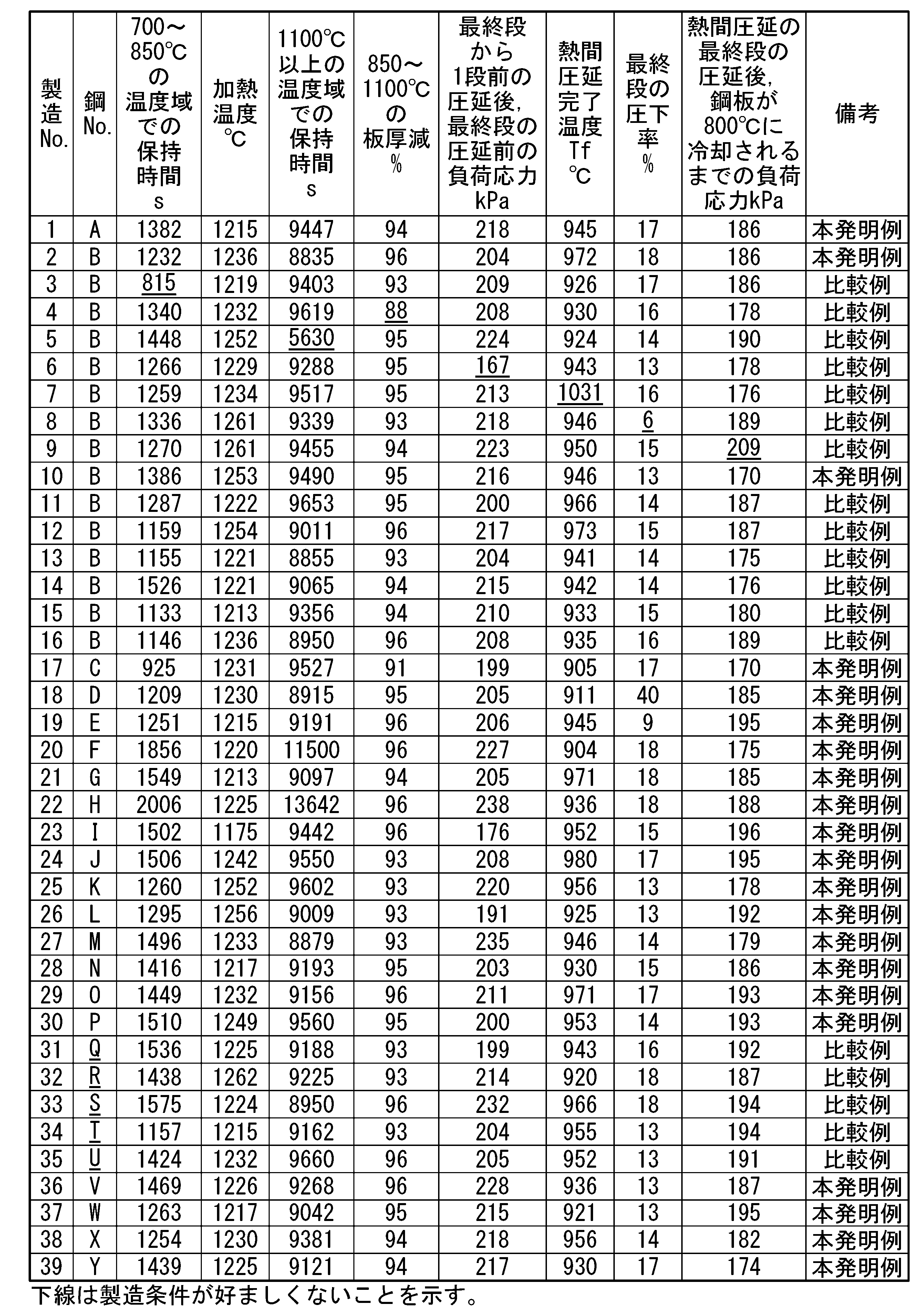


一方、比較例に係る熱間圧延鋼板は、強度、延性、限界破断板厚減少率およびせん断加工性のいずれか1つ以上が劣化していることが分かる。
本発明に係る熱間圧延鋼板は、自動車部材、機械構造部材さらには建築部材に用いられる工業用素材として好適である。
Claims (3)
- 化学組成が、質量%で、
C :0.050~0.250%、
Si:0.05~3.00%、
Mn:1.00~4.00%、
sol.Al:0.001~2.000%、
P :0.100%以下、
S :0.0300%以下、
N :0.1000%以下、
O :0.0100%以下、
Ti:0~0.500%、
Nb:0~0.500%、
V :0~0.500%、
Cu:0~2.00%、
Cr:0~2.00%、
Mo:0~1.00%、
Ni:0~2.00%、
B :0~0.0100%、
Ca:0~0.0200%、
Mg:0~0.0200%、
REM:0~0.1000%、
Bi:0~0.0200%、
As:0~0.100%、
Zr:0~1.00%、
Co:0~1.00%、
Zn:0~1.00%、
W :0~1.00%、
Sn:0~0.05%、並びに
残部:Feおよび不純物であり、
下記式(A)および(B)を満たし、
金属組織が、面積%で、
残留オーステナイトが3.0%未満であり、
フェライトが15.0%以上、60.0%未満であり、
パーライトが5.0%未満であり、
グレーレベル共起行列法により、前記金属組織のSEM画像を解析することによって得られる、下記式(1)で示されるEntropy値が10.7以上であり、
下記式(2)で示されるInverce differenced normalized値が1.020以上であり、
下記式(3)で示されるCluster Shade値が-8.0×10⁵~8.0×10⁵であり、
Mn濃度の標準偏差が0.60質量%以下であり、
引張強さが980MPa以上である
ことを特徴とする熱間圧延鋼板。
0.060%≦Ti+Nb+V≦0.500% …(A)
Zr+Co+Zn+W≦1.00% …(B)
ただし、前記式(A)および(B)中の各元素記号は、当該元素の質量%での含有量を示し、当該元素を含有しない場合は0%を代入する。
ここで、下記式(1)~(5)中のP(i,j)はグレーレベル共起行列であり、下記式(2)中のLは前記SEM画像の取り得るグレースケールのレベル数であり、下記式(2)および(3)中のiおよびjは1~前記Lの自然数であり、下記式(3)中のμxおよびμyはそれぞれ下記式(4)および(5)で示される。




- 表層の平均結晶粒径が3.0μm未満であることを特徴とする請求項1に記載の熱間圧延鋼板。
- 前記化学組成が、質量%で、
Ti:0.001~0.500%、
Nb:0.001~0.500%、
V :0.001~0.500%、
Cu:0.01~2.00%、
Cr:0.01~2.00%、
Mo:0.01~1.00%、
Ni:0.01~2.00%、
B :0.0001~0.0100%、
Ca:0.0001~0.0200%、
Mg:0.0001~0.0200%、
REM:0.0001~0.1000%、
Bi:0.0001~0.0200%、
As:0.001~0.100%、
Zr:0.01~1.00%、
Co:0.01~1.00%、
Zn:0.01~1.00%、
W :0.01~1.00%、および
Sn:0.01~0.05%
からなる群から選択される1種または2種以上を含有する
ことを特徴とする請求項1または2に記載の熱間圧延鋼板。
Priority Applications (6)
| Application Number | Priority Date | Filing Date | Title |
|---|---|---|---|
| EP22880706.1A EP4417714A4 (en) | 2021-10-11 | 2022-09-14 | HOT ROLLED STEEL SHEET |
| KR1020247006624A KR102897769B1 (ko) | 2021-10-11 | 2022-09-14 | 열간 압연 강판 |
| US18/689,095 US20240384378A1 (en) | 2021-10-11 | 2022-09-14 | Hot-rolled steel sheet |
| JP2023555042A JP7648952B2 (ja) | 2021-10-11 | 2022-09-14 | 熱間圧延鋼板 |
| MX2024002707A MX2024002707A (es) | 2021-10-11 | 2022-09-14 | Lamina de acero laminada en caliente. |
| CN202280060328.5A CN117940597A (zh) | 2021-10-11 | 2022-09-14 | 热轧钢板 |
Applications Claiming Priority (2)
| Application Number | Priority Date | Filing Date | Title |
|---|---|---|---|
| JP2021-166958 | 2021-10-11 | ||
| JP2021166958 | 2021-10-11 |
Publications (1)
| Publication Number | Publication Date |
|---|---|
| WO2023063010A1 true WO2023063010A1 (ja) | 2023-04-20 |
Family
ID=85987411
Family Applications (1)
| Application Number | Title | Priority Date | Filing Date |
|---|---|---|---|
| PCT/JP2022/034395 Ceased WO2023063010A1 (ja) | 2021-10-11 | 2022-09-14 | 熱間圧延鋼板 |
Country Status (7)
| Country | Link |
|---|---|
| US (1) | US20240384378A1 (ja) |
| EP (1) | EP4417714A4 (ja) |
| JP (1) | JP7648952B2 (ja) |
| KR (1) | KR102897769B1 (ja) |
| CN (1) | CN117940597A (ja) |
| MX (1) | MX2024002707A (ja) |
| WO (1) | WO2023063010A1 (ja) |
Cited By (2)
| Publication number | Priority date | Publication date | Assignee | Title |
|---|---|---|---|---|
| JPWO2024053701A1 (ja) * | 2022-09-08 | 2024-03-14 | ||
| WO2024080327A1 (ja) * | 2022-10-12 | 2024-04-18 | 日本製鉄株式会社 | 熱延鋼板 |
Families Citing this family (3)
| Publication number | Priority date | Publication date | Assignee | Title |
|---|---|---|---|---|
| MX2023002114A (es) | 2020-08-27 | 2023-03-15 | Nippon Steel Corp | Lamina de acero laminada en caliente. |
| WO2022044495A1 (ja) * | 2020-08-27 | 2022-03-03 | 日本製鉄株式会社 | 熱延鋼板 |
| JP7564464B2 (ja) | 2020-08-27 | 2024-10-09 | 日本製鉄株式会社 | 熱延鋼板 |
Citations (6)
| Publication number | Priority date | Publication date | Assignee | Title |
|---|---|---|---|---|
| WO2014166323A1 (zh) * | 2013-04-09 | 2014-10-16 | 宝山钢铁股份有限公司 | 一种700MPa级高强度热轧Q&P钢及其制造方法 |
| JP2015098629A (ja) * | 2013-11-19 | 2015-05-28 | 新日鐵住金株式会社 | 熱延鋼板 |
| JP2015214718A (ja) * | 2014-05-08 | 2015-12-03 | 新日鐵住金株式会社 | 熱延鋼板およびその製造方法 |
| WO2020044445A1 (ja) | 2018-08-28 | 2020-03-05 | Jfeスチール株式会社 | 熱延鋼板及びその製造方法、冷延鋼板及びその製造方法、冷延焼鈍鋼板の製造方法、並びに溶融亜鉛めっき鋼板の製造方法 |
| WO2020184372A1 (ja) * | 2019-03-11 | 2020-09-17 | 日本製鉄株式会社 | 熱延鋼板 |
| JP2021166958A (ja) | 2020-04-10 | 2021-10-21 | 品川リフラクトリーズ株式会社 | 水添加機構 |
Family Cites Families (2)
| Publication number | Priority date | Publication date | Assignee | Title |
|---|---|---|---|---|
| US11313009B2 (en) * | 2017-07-07 | 2022-04-26 | Nippon Steel Corporation | Hot-rolled steel sheet and method for manufacturing same |
| CN114929915B (zh) * | 2020-01-27 | 2023-10-27 | 日本制铁株式会社 | 热轧钢板 |
-
2022
- 2022-09-14 JP JP2023555042A patent/JP7648952B2/ja active Active
- 2022-09-14 EP EP22880706.1A patent/EP4417714A4/en active Pending
- 2022-09-14 CN CN202280060328.5A patent/CN117940597A/zh active Pending
- 2022-09-14 US US18/689,095 patent/US20240384378A1/en active Pending
- 2022-09-14 KR KR1020247006624A patent/KR102897769B1/ko active Active
- 2022-09-14 MX MX2024002707A patent/MX2024002707A/es unknown
- 2022-09-14 WO PCT/JP2022/034395 patent/WO2023063010A1/ja not_active Ceased
Patent Citations (6)
| Publication number | Priority date | Publication date | Assignee | Title |
|---|---|---|---|---|
| WO2014166323A1 (zh) * | 2013-04-09 | 2014-10-16 | 宝山钢铁股份有限公司 | 一种700MPa级高强度热轧Q&P钢及其制造方法 |
| JP2015098629A (ja) * | 2013-11-19 | 2015-05-28 | 新日鐵住金株式会社 | 熱延鋼板 |
| JP2015214718A (ja) * | 2014-05-08 | 2015-12-03 | 新日鐵住金株式会社 | 熱延鋼板およびその製造方法 |
| WO2020044445A1 (ja) | 2018-08-28 | 2020-03-05 | Jfeスチール株式会社 | 熱延鋼板及びその製造方法、冷延鋼板及びその製造方法、冷延焼鈍鋼板の製造方法、並びに溶融亜鉛めっき鋼板の製造方法 |
| WO2020184372A1 (ja) * | 2019-03-11 | 2020-09-17 | 日本製鉄株式会社 | 熱延鋼板 |
| JP2021166958A (ja) | 2020-04-10 | 2021-10-21 | 品川リフラクトリーズ株式会社 | 水添加機構 |
Non-Patent Citations (4)
| Title |
|---|
| D. L. NAIKH. U. SAJIDR. KIRAN, METALS, vol. 9, 2019, pages 546 |
| J. WEBELJ. GOLAD. BRITZF. MUCKLICH, MATERIALS CHARACTERIZATION, vol. 144, 2018, pages 584 - 596 |
| K. ZUIDERVELD: "Contrast Limited Adaptive Histogram Equalization", vol. 5, 1994, ACADEMIC PRESS, article "Graphics Gems IV", pages: 474 - 485 |
| See also references of EP4417714A4 |
Cited By (4)
| Publication number | Priority date | Publication date | Assignee | Title |
|---|---|---|---|---|
| JPWO2024053701A1 (ja) * | 2022-09-08 | 2024-03-14 | ||
| WO2024053701A1 (ja) * | 2022-09-08 | 2024-03-14 | 日本製鉄株式会社 | 熱延鋼板 |
| WO2024080327A1 (ja) * | 2022-10-12 | 2024-04-18 | 日本製鉄株式会社 | 熱延鋼板 |
| JPWO2024080327A1 (ja) * | 2022-10-12 | 2024-04-18 |
Also Published As
| Publication number | Publication date |
|---|---|
| KR20240042470A (ko) | 2024-04-02 |
| US20240384378A1 (en) | 2024-11-21 |
| KR102897769B1 (ko) | 2025-12-11 |
| EP4417714A1 (en) | 2024-08-21 |
| CN117940597A (zh) | 2024-04-26 |
| JPWO2023063010A1 (ja) | 2023-04-20 |
| MX2024002707A (es) | 2024-03-20 |
| JP7648952B2 (ja) | 2025-03-19 |
| EP4417714A4 (en) | 2025-05-28 |
Similar Documents
| Publication | Publication Date | Title |
|---|---|---|
| JP7239009B2 (ja) | 熱延鋼板 | |
| JP7495640B2 (ja) | 熱延鋼板 | |
| JP7648952B2 (ja) | 熱間圧延鋼板 | |
| JP7260824B2 (ja) | 熱延鋼板 | |
| JP7741418B2 (ja) | 熱延鋼板 | |
| JP7564464B2 (ja) | 熱延鋼板 | |
| JP7495641B2 (ja) | 熱延鋼板 | |
| JP7564463B2 (ja) | 熱延鋼板 | |
| JP7260825B2 (ja) | 熱延鋼板 | |
| KR20250114345A (ko) | 열연 강판 | |
| JP7648953B2 (ja) | 熱間圧延鋼板 | |
| US20260022442A1 (en) | Hot-rolled steel sheet | |
| JP7440804B2 (ja) | 熱間圧延鋼板 | |
| US20260085393A1 (en) | Hot-rolled steel sheet | |
| US20260085392A1 (en) | Hot-rolled steel sheet | |
| WO2025197753A1 (ja) | 鋼板、それを含む部品及び鋼板の製造方法 | |
| WO2024080327A1 (ja) | 熱延鋼板 |
Legal Events
| Date | Code | Title | Description |
|---|---|---|---|
| 121 | Ep: the epo has been informed by wipo that ep was designated in this application |
Ref document number: 22880706 Country of ref document: EP Kind code of ref document: A1 |
|
| WWE | Wipo information: entry into national phase |
Ref document number: 2023555042 Country of ref document: JP |
|
| WWE | Wipo information: entry into national phase |
Ref document number: 202417013696 Country of ref document: IN |
|
| WWE | Wipo information: entry into national phase |
Ref document number: 1020247006624 Country of ref document: KR |
|
| WWE | Wipo information: entry into national phase |
Ref document number: 18689095 Country of ref document: US |
|
| WWE | Wipo information: entry into national phase |
Ref document number: 202280060328.5 Country of ref document: CN |
|
| WWE | Wipo information: entry into national phase |
Ref document number: 2022880706 Country of ref document: EP |
|
| NENP | Non-entry into the national phase |
Ref country code: DE |
|
| ENP | Entry into the national phase |
Ref document number: 2022880706 Country of ref document: EP Effective date: 20240513 |