WO2023063140A1 - 駆動装置及び駆動装置ユニット - Google Patents
駆動装置及び駆動装置ユニット Download PDFInfo
- Publication number
- WO2023063140A1 WO2023063140A1 PCT/JP2022/036949 JP2022036949W WO2023063140A1 WO 2023063140 A1 WO2023063140 A1 WO 2023063140A1 JP 2022036949 W JP2022036949 W JP 2022036949W WO 2023063140 A1 WO2023063140 A1 WO 2023063140A1
- Authority
- WO
- WIPO (PCT)
- Prior art keywords
- fins
- motor
- peripheral surface
- fin
- outer peripheral
- Prior art date
- Legal status (The legal status is an assumption and is not a legal conclusion. Google has not performed a legal analysis and makes no representation as to the accuracy of the status listed.)
- Ceased
Links
Images














Classifications
-
- B—PERFORMING OPERATIONS; TRANSPORTING
- B64—AIRCRAFT; AVIATION; COSMONAUTICS
- B64D—EQUIPMENT FOR FITTING IN OR TO AIRCRAFT; FLIGHT SUITS; PARACHUTES; ARRANGEMENT OR MOUNTING OF POWER PLANTS OR PROPULSION TRANSMISSIONS IN AIRCRAFT
- B64D33/00—Arrangement in aircraft of power plant parts or auxiliaries not otherwise provided for
- B64D33/08—Arrangement in aircraft of power plant parts or auxiliaries not otherwise provided for of power plant cooling systems
- B64D33/10—Radiator arrangement
-
- B—PERFORMING OPERATIONS; TRANSPORTING
- B64—AIRCRAFT; AVIATION; COSMONAUTICS
- B64D—EQUIPMENT FOR FITTING IN OR TO AIRCRAFT; FLIGHT SUITS; PARACHUTES; ARRANGEMENT OR MOUNTING OF POWER PLANTS OR PROPULSION TRANSMISSIONS IN AIRCRAFT
- B64D33/00—Arrangement in aircraft of power plant parts or auxiliaries not otherwise provided for
- B64D33/08—Arrangement in aircraft of power plant parts or auxiliaries not otherwise provided for of power plant cooling systems
-
- H—ELECTRICITY
- H02—GENERATION; CONVERSION OR DISTRIBUTION OF ELECTRIC POWER
- H02K—DYNAMO-ELECTRIC MACHINES
- H02K5/00—Casings; Enclosures; Supports
- H02K5/04—Casings or enclosures characterised by the shape, form or construction thereof
- H02K5/18—Casings or enclosures characterised by the shape, form or construction thereof with ribs or fins for improving heat transfer
-
- H—ELECTRICITY
- H02—GENERATION; CONVERSION OR DISTRIBUTION OF ELECTRIC POWER
- H02K—DYNAMO-ELECTRIC MACHINES
- H02K5/00—Casings; Enclosures; Supports
- H02K5/04—Casings or enclosures characterised by the shape, form or construction thereof
- H02K5/22—Auxiliary parts of casings not covered by groups H02K5/06-H02K5/20, e.g. shaped to form connection boxes or terminal boxes
-
- B—PERFORMING OPERATIONS; TRANSPORTING
- B64—AIRCRAFT; AVIATION; COSMONAUTICS
- B64D—EQUIPMENT FOR FITTING IN OR TO AIRCRAFT; FLIGHT SUITS; PARACHUTES; ARRANGEMENT OR MOUNTING OF POWER PLANTS OR PROPULSION TRANSMISSIONS IN AIRCRAFT
- B64D27/00—Arrangement or mounting of power plants in aircraft; Aircraft characterised by the type or position of power plants
- B64D27/02—Aircraft characterised by the type or position of power plants
- B64D27/30—Aircraft characterised by electric power plants
- B64D27/34—All-electric aircraft
Definitions
- the disclosure in this specification relates to a driving device and a driving device unit.
- Patent Document 1 discloses a drive device mounted on an electric vertical take-off and landing aircraft. This drive is an EDS that drives the rotor to rotate.
- the drive device has a motor and a drive section.
- the drive section has an inverter circuit and the like, and drives the motor to rotate.
- the driving device rotates the rotor by rotating the motor.
- the drive device it is conceivable that heat is generated due to the rotation of the motor and the drive of the drive unit. Therefore, in order to enhance the heat radiation effect, the drive device is often provided with a large number of heat radiation fins in the housing containing the motor and the drive section.
- the driving device if the number of heat radiating fins is large, the heat radiating effect is likely to be improved, but there is a concern that the driving device will become too heavy when mounted on an aircraft such as an electric vertical take-off and landing aircraft.
- a main object of the present disclosure is to provide a drive device and a drive device unit suitable for mounting on an aircraft.
- the disclosed aspects include: A driving device that drives to rotate a rotor of an aircraft, a heating element that generates heat when driven to rotate the rotor; a housing having an outer peripheral surface extending along the axis of rotation of the gas-conveying fan and containing a heating element; radiation fins extending along the outer peripheral surface in the axial direction in which the rotation axis extends and releasing heat from the heating element to the gas flowing along the outer peripheral surface due to the rotation of the fan; with In the driving device, as the radiation fins, inclined fins, at least a part of which is inclined in the circumferential direction of the rotation axis, are provided on the outer peripheral surface.
- the outer peripheral surface of the housing is provided with inclined fins, at least a portion of which is inclined in the circumferential direction with respect to the rotation axis.
- the inclined fins can guide the gas flowing along the outer peripheral surface of the housing so as to increase the cooling effect for the drive device. Therefore, even if the number and size of the fins including the inclined fins are limited so that the driving device does not become too heavy for the aircraft, the inclined fins can prevent the cooling effect of the driving device from being lowered. Therefore, it is possible to improve the cooling effect and reduce the weight of the drive device at the same time by using the inclined fins. In this way, a driving device suitable for mounting on an aircraft can be realized.
- the drive is a heating element that generates heat when driven to rotate the rotor; a housing having an outer peripheral surface extending along the axis of rotation of the gas-conveying fan and containing a heating element; radiation fins extending along the outer peripheral surface in the axial direction in which the rotation axis extends and releasing heat from the heating element to the gas flowing along the outer peripheral surface due to the rotation of the fan; has In the drive unit, an inclined fin, at least part of which is inclined with respect to the rotation axis in the circumferential direction of the rotation axis, is provided on the outer peripheral surface as the radiation fin.
- the same effects as those of the drive device can be obtained. This makes it possible to realize a drive unit suitable for mounting on an aircraft.
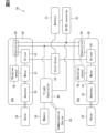
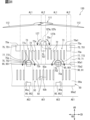
- FIG. 2 is a block diagram showing the electrical configuration of EDS in eVTOL; A perspective view of a rotor and an EDS unit. A perspective view of an EDS.
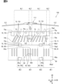
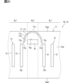
- FIG. 10 is a partially developed view of the outer peripheral surfaces of the motor and the inverter in Modification 1-1;
- FIG. 11 is a partially expanded view of the outer peripheral surfaces of the motor and the inverter in modification 1-2;
- FIG. 10 is a partially developed view of the outer peripheral surfaces of the motor and the inverter in Modification 1-1;
- FIG. 11 is a partially expanded view of the outer peripheral surfaces of the motor and the inverter in modification 1-2;
- FIG. 11 is a partially expanded view of the outer peripheral surfaces of the motor and the inverter in modification 1-3;
- FIG. 10 is a partially expanded view of the outer peripheral surfaces of the motor and the inverter in modification 1-4;
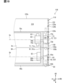
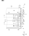
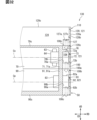
- FIG. 11 is a partial vertical cross-sectional view of a motor and an inverter in modification 1-5; The figure which expanded
- FIG. 11 is a partially developed view of the outer peripheral surfaces of the motor and the inverter in modification 2-1; The figure which expanded
- FIG. 20 is an enlarged view of the periphery of the exposed guide plate in FIG. 20; Partial longitudinal sectional view of a motor and an inverter.
- FIG. 20 is an enlarged view of the periphery of the high heat induction plate in FIG.
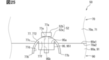
- FIG. 12 is an enlarged view of the periphery of the exposed guide plate in modification 5-1;
- FIG. 20 is an enlarged view of the periphery of the exposed guide plate in modification 5-1;
- FIG. 12 is an enlarged view of the periphery of the high heat induction plate in modification 5-2;
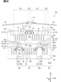
- FIG. 12 is a partially expanded view of the outer peripheral surfaces of the motor and the inverter in modification 5-3;
- FIG. 12 is an enlarged view of the periphery of the exposed guide plate in modification 5-4;
- FIG. 28 is an enlarged view of the periphery of the exposed guide plate in FIG. 28 ; Partial longitudinal sectional view of a motor and an inverter.
- FIG. 11 is a partially developed view of the outer peripheral surfaces of the motor and the inverter in modification 5-5;
- FIG. 12 is a partially developed view of the outer peripheral surfaces of the motor and the inverter in modification 5-6;
- a drive system 30 shown in FIG. 1 is mounted on the eVTOL 10 .
- the eVTOL 10 is an electric vertical takeoff and landing aircraft, and can take off and land vertically.
- eVTOL is an abbreviation for electric Vertical Take-Off and Landing aircraft.
- the eVTOL 10 is an aircraft that flies in the atmosphere and corresponds to an aircraft.
- the eVTOL 10 is a manned aircraft with a crew on board.
- the drive system 30 is a system that drives the eVTOL 10 to fly.
- the eVTOL 10 has a fuselage 11 and a rotor 20.
- the fuselage 11 has a fuselage body 12 and wings 13 .
- the fuselage body 12 is the body of the fuselage 11, and has a shape extending forward and backward, for example.
- the fuselage body 12 has a passenger compartment in which a passenger rides.
- the wings 13 extend from the fuselage body 12 and are provided in plurality on the fuselage body 12 .
- Wing 13 is a fixed wing.
- the multiple wings 13 include main wings, tail wings, and the like.
- a plurality of rotors 20 shown in FIGS. 1 and 3 are provided on the airframe 11 .
- the rotors 20 are provided on each of the fuselage body 12 and the wings 13 .
- the rotor 20 rotates around a motor axis Cm, which will be described later.
- the rotation axis of the rotor 20 is the motor axis Cm.
- Motor axis Cm coincides with the centerline of rotor 20 . If the direction in which the motor axis Cm extends is called the axial direction AD, the axial direction AD, the radial direction RD, and the circumferential direction CD of the motor axis Cm are orthogonal to each other.
- the rotor 20 rotates in the circumferential direction CD.
- the outer side in the radial direction RD may be referred to as the radial outer side
- the inner side in the radial direction RD may be referred to as the radial inner side.
- the rotor 20 has blades 21 , a rotor head 22 and a rotor shaft 23 .
- a plurality of blades 21 are arranged in the circumferential direction CD.
- the rotor head 22 connects multiple blades 21 .
- the blades 21 extend from the rotor head 22 in the radial direction RD.
- the blades 21 are vanes that rotate together with the rotor shaft 23 .
- the rotor shaft 23 is the rotating shaft of the rotor 20 and extends from the rotor head 22 along the motor axis Cm.
- the eVTOL10 is a tilt rotor machine.
- the eVTOL 10 allows the rotor 20 to be tilted. That is, the tilt angle of the rotor 20 is adjustable.
- the orientation of the rotor 20 is set such that the motor axis Cm extends vertically.
- rotor 20 functions as a lift rotor for generating lift in eVTOL 10 . That is, the rotor 20 can serve as a rotating blade.
- the orientation of the rotor 20 is set so that the motor axis Cm extends in the front-rear direction. In this case, rotor 20 functions as a cruising rotor for generating thrust in eVTOL 10 .
- the wing 13 can be tilted relative to the fuselage body 12. That is, it is possible to tilt the rotor 20 together with the blades 13 .
- the tilt angle of the rotor 20 is adjusted by adjusting the inclination angle of the wing 13 with respect to the airframe body 12 .
- the eVTOL 10 may allow the rotor 20 to tilt relative to the fuselage 11 .
- the tilt angle of the rotor 20 may be adjusted by adjusting the tilt angle of the rotor 20 relative to the blades 13 .
- the drive system 30 has a battery 31, a distributor 32, a converter 33, a communication device 34, a storage device 35, a flight control device 40, and an EDS 50.
- FIG. 2 shows the rotor 20 as Rotor, the battery 31 as Battery, the distributor 32 as Distributor, and the converter 33 as DC-DC converter.
- the communication device 34 is illustrated as Communication Device, the storage device 35 as Memory, and the flight control device 40 as Flight Controller.
- the battery 31 is electrically connected to multiple EDSs 50 .
- the battery 31 is a power supply unit that supplies power to the EDS 50 and corresponds to a power supply unit.
- a battery 31 is a DC voltage source that applies a DC voltage to the EDS 50 .
- the battery 31 has a rechargeable secondary battery.
- Such secondary batteries include lithium-ion batteries, nickel-metal hydride batteries, and the like.
- As the power supply unit in addition to or instead of the battery 31, a fuel cell, a generator, or the like may be used.
- the distributor 32 is electrically connected to the battery 31 and multiple EDSs 50 .
- the distributor 32 distributes power from the battery 31 to the multiple EDSs 50 .
- a driving section 81 (to be described later) is electrically connected to the distributor 32 . Electric power from the battery 31 is supplied to the drive unit 81 via the distributor 32 . If the voltage of the battery 31 is referred to as a high voltage, a high voltage is applied to the drive section 81 .
- the distributor 32 may be omitted as long as the power of the battery 31 is supplied to a plurality of EDSs 50 . As a configuration that does not require the distributor 32, for example, there is a configuration in which each of the plurality of EDSs 50 is individually provided with a power supply unit.
- the flight control device 40 is an ECU, for example, and controls the driving of the EDS 50.
- ECU is an abbreviation for Electronic Control Unit.
- the flight control device 40 is mainly composed of a microcomputer having, for example, a processor, memory, I/O, and a bus connecting them.
- a microcomputer is sometimes called a microcomputer.
- a memory is a non-transitory physical storage medium that non-temporarily stores computer-readable programs and data.
- a non-transitory tangible storage medium is a non-transitory tangible storage medium, which is realized by a semiconductor memory, a magnetic disk, or the like.
- the flight control device 40 is electrically connected to the storage device 35 and the EDS 50.
- the flight control device 40 executes a control program stored in at least one of the memory and the storage device 35 to execute various processes related to driving the EDS 50 .
- the flight control device 40 performs flight control for causing the eVTOL 10 to fly.
- This flight control includes control of the EDS 50, tilt angle control for changing the tilt angle of the rotor 20, and the like.
- a later-described drive control section 54 is electrically connected to the flight control device 40 .
- the flight control device 40 controls the EDS 50 by outputting a control signal to the drive control section 54 .
- the converter 33 is electrically connected to the battery 31, the flight control device 40 and the EDS 50.
- drive control section 54 is electrically connected to converter 33 .
- the converter 33 steps down or steps up the electric power from the battery 31 and supplies it to the flight control device 40 and the drive control section 54 . If the voltage of the power stepped down by the converter 33 is referred to as a low voltage, the low voltage is applied to the flight control device 40 and the drive control section 54 . This low voltage is a voltage lower than the voltage of the battery 31 . Conversely, if the voltage of the electric power boosted by the converter 33 is called a high voltage, the high voltage is applied to the flight control device 40 and the drive control section 54 . This high voltage is a voltage higher than the voltage of the battery 31 .
- the EDS 50 is a device that drives to rotate the rotor 20 and corresponds to a drive device.
- the EDS 50 is rotationally driven with respect to the rotor 20 .
- EDS50 is an abbreviation for Electric Drive System.
- the EDS 50 is sometimes referred to as an electric drive and an EPU.
- EPU is an abbreviation for Electric Propulsion Unit.
- the EDS 50 is individually provided for each of the multiple rotors 20 .
- the EDS 50 is aligned with the rotor 20 along the motor axis Cm. All of the multiple EDSs 50 are fixed to the fuselage 11 .
- EDS 50 rotatably supports rotor 20 .
- EDS 50 is mechanically connected to rotor shaft 23 .
- the plurality of EDSs 50 include at least one of the EDS 50 fixed to the body 11 in a state protruding outside the body 11 and the EDS 50 fixed to the body 11 in a state embedded inside the body 11. .
- the rotor 20 is fixed to the airframe 11 via the EDS 50.
- the EDS 50 is designed not to tilt relative to the rotor 20 .
- the EDS 50 can tilt relative to the airframe 11 together with the rotor 20 .
- the orientation of EDS 50 is set along with rotor 20 .
- the EDS 50 has a gearbox 53, a drive control section 54, a rotation sensor 55, a motor 61, and a drive section 81.
- the gearbox 53 is shown as Gearbox
- the drive unit 81 as Driver
- the drive control unit 54 as Controller
- the rotation sensor 55 as Rotation sensor
- the motor 61 as Motor.
- the motor 61 is a multi-phase AC motor, such as a three-phase AC rotary electric machine.
- the motor 61 functions as an electric motor that is the flight drive source of the eVTOL 10 .
- the motor 61 has a rotor and a stator.
- the motor 61 is electrically connected to the driving section 81 . Electric power is supplied to the motor 61 from the battery 31 through the drive unit 81 .
- the motor 61 is driven according to voltage and current supplied from the driving section 81 .
- a brushless motor for example, is used as the motor 61 .
- As the motor 61 an induction motor or a reactance motor may be used.
- the gearbox 53 mechanically connects the motor 61 and the rotor 20 .
- the rotor shaft 23 is mechanically connected to the rotating shaft of the motor 61 via the gearbox 53 .
- the gearbox 53 reduces the speed of rotation of the motor 61 and transmits it to the rotor 20 .
- the gearbox 53 is configured including a plurality of gears, and is sometimes called a transmission gear and a speed reducer.
- the gearbox 53 has a structure adapted to the motor characteristics of the motor 61 .
- the drive unit 81 drives the motor 61 by converting electric power supplied to the motor 61 .
- the drive unit 81 has an inverter.
- the inverter converts the power supplied to the motor 61 from direct current to alternating current.
- An inverter is a power converter that converts power.
- the inverter is a multiple-phase inverter, and performs power conversion for each of the multiple phases.
- the inverter is, for example, a three-phase inverter.
- the inverter is an inverter circuit including a plurality of switching elements.
- the switching elements include power elements such as IGBTs and MOSFETs.
- IGBT is an abbreviation for Insulated Gate Bipolar Transistor.
- MOSFET is an abbreviation for Metal-Oxide-Semiconductor Field-Effect Transistor.
- a switching element is sometimes referred to as a driving element.
- switching elements are connected in parallel in each of the multiple phases.
- the motor 61 is a three-phase AC motor
- a plurality of switching elements are connected in parallel to the motor 61 in each of the U-phase, V-phase, and W-phase.
- the plurality of switching elements may not be connected in parallel in each of the plurality of phases.
- a plurality of switching elements may not be connected in parallel to the motor 61 in each of the U-phase, V-phase, and W-phase.
- the rotation sensor 55 is provided for the motor 61.
- the rotation sensor 55 is a rotation detector that detects the rotation speed and rotation angle of the motor 61 .
- the rotation sensor 55 outputs a detection signal corresponding to the rotation speed of the motor 61 to the drive control section 54 .
- the rotation sensor 55 includes, for example, an encoder and a resolver.
- the drive control unit 54 is an ECU, for example, and controls the drive unit 81 .
- the drive control unit 54 is mainly composed of a microcomputer having, for example, a processor, memory, I/O, and a bus connecting them.
- the drive control section 54 is electrically connected to the flight control device 40 and the drive section 81 .
- the drive control unit 54 is electrically connected to various sensors including the rotation sensor 55 .
- the drive control unit 54 controls the drive unit 81 by outputting command signals to the drive unit 81 .
- the drive control unit 54 generates command signals according to control signals input from the flight control device 40, detection signals input from various sensors such as the rotation sensor 55, and the like.
- the inverter drives according to the command signal input from the drive control unit 54, and power conversion is performed by the inverter.
- Various sensors include, in addition to the rotation sensor 55, a current sensor and a voltage sensor.
- the current sensor detects, for example, the current flowing through the motor 61 for each of multiple phases.
- the voltage sensor detects voltage output from the battery 31, for example.
- the rotor 20 and the EDS 50 are arranged along the motor axis Cm.
- the rotor 20 rotates to send air to one side in the axial direction AD, thereby generating thrust and lift in the eVTOL 10 .
- the rotor 20 sends air toward the EDS 50 side in the axial direction AD.
- a swirling flow is generated along the motor axis Cm. In this swirling flow, the air flows in the axial direction AD while swirling in the circumferential direction CD.
- the EDS 50 has a motor device 60, an inverter device 80 and a fin cover 100.
- the motor device 60 has a motor 61 and a motor housing 70 .
- Motor housing 70 accommodates motor 61 .
- the motor 61 has a motor shaft 62 .
- the motor shaft 62 is the rotating shaft of the motor 61 and rotates together with the rotor. If the rotation of the rotor is referred to as the rotation of the motor 61, the motor 61 rotates around the motor axis Cm.
- a motor axis Cm is a virtual line extending linearly and coincides with the center line of the motor 61 .
- the motor shaft 62 extends along the motor axis Cm.
- the inverter device 80 has a drive section 81 and an inverter housing 90 .
- Inverter housing 90 accommodates drive unit 81 .
- Motor device 60 and inverter device 80 are arranged along motor axis Cm.
- the motor housing 70 and the inverter housing 90 are arranged along the motor axis Cm.
- the motor housing 70 and the inverter housing 90 are formed in a tubular shape as a whole and extend along the motor axis Cm.
- the motor housing 70 and the inverter housing 90 are stacked on each other in the axial direction AD.
- the motor housing 70 and the inverter housing 90 are fixed to each other by fasteners such as bolts.
- the motor housing 70 and the inverter housing 90 are made of metal material or the like, and have thermal conductivity.
- the motor housing 70 and the inverter housing 90 constitute the housing of the EDS 50.
- the motor 61 and the driving section 81 are driven to rotate the rotor 20, and the driving tends to generate heat.
- the motor 61 and the driving section 81 correspond to the heating element, and the motor housing 70 and the inverter housing 90 correspond to the housing.
- the outer peripheral surface 70a of the motor housing 70 and the outer peripheral surface 90a of the inverter housing 90 correspond to the outer peripheral surface of the housing.
- These outer peripheral surfaces 70a and 90a are arranged in the axial direction AD.
- the outer peripheral surfaces 70a and 90a form a continuous surface extending continuously in the axial direction AD.
- the fin cover 100 accommodates the motor housing 70 and the inverter housing 90.
- the fin cover 100 has a tubular shape as a whole and extends along the motor axis Cm.
- the fin cover 100 spans over the motor housing 70 and the inverter housing 90 in the axial direction AD.
- the fin cover 100 covers the motor housing 70 and the inverter housing 90 from the outer peripheral side.
- the fin cover 100 is provided outside the motor housing 70 and the inverter housing 90 in the radial direction RD and extends along the outer peripheral surfaces 70a, 90a.
- the fin cover 100 is sometimes called a duct.
- the fin cover 100 is made of a resin material or the like and is elastically deformable.
- the fin cover 100 is attached to the motor housing 70 and the inverter housing 90 in an elastically deformed state.
- the fin cover 100 extends at least radially outward due to elastic deformation, and is held in position relative to the motor housing 70 and the inverter housing 90 by a restoring force directed radially inward.
- the fin cover 100 is attached to the motor housing 70 and the inverter housing 90 using the restoring force due to elastic deformation.
- the fin cover 100 corresponds to a housing cover.
- the thermal conductivity of the fin cover 100 is lower than that of the motor housing 70 and inverter housing 90 .
- a blower device 110 is attached to the EDS 50 .
- the blower device 110 is attached to the EDS 50 and constitutes an EDS unit 130 together with the EDS 50 .
- EDS unit 130 is mounted on eVTOL 10 .
- the blower device 110 is arranged along the motor axis Cm with respect to the rotor 20 and the EDS 50 .
- the blower device 110 is provided between the rotor 20 and the EDS 50 in the axial direction AD.
- the EDS unit 130 corresponds to the drive unit.
- the air blower 110 sends air by driving.
- the blower device 110 has a blower fan 111 and a shroud 120 .
- the blower fan 111 rotates around the motor axis Cm.
- the rotation axis of the blower fan 111 is the motor axis Cm.
- the centerline of the blower fan 111 coincides with the motor axis Cm.
- the blower fan 111 sends air toward the EDS 50 in the axial direction AD by rotating.
- Blower fan 111 sends cooling air toward EDS 50 for cooling EDS 50 .
- the side of the blower fan 111 is the upstream side of the EDS 50 .
- both the swirling flow caused by the blower fan 111 and the swirling flow caused by the rotor 20 are clockwise swirling flows that advance while swirling clockwise.
- the blower fan 111 has fan blades 112 and a fan shaft 113 .
- a plurality of fan blades 112 are arranged in the circumferential direction CD. Fan blades 112 are connected by a fan head. Fan blades 112 extend radially RD from the fan head. Fan blades 112 are blades that rotate together with fan shaft 113 .
- the fan shaft 113 is the rotating shaft of the blower fan 111 and extends from the fan head along the motor axis Cm.
- the shroud 120 houses the blower fan 111.
- Shroud 120 is formed in a tubular shape and extends along motor axis Cm.
- the shroud 120 is provided outside the blower fan 111 in the radial direction RD.
- Shroud 120 is attached to EDS 50 .
- the shroud 120 is fixed to the motor housing 70, for example.
- the shroud 120 is made of a resin material or the like.
- Shroud 120 has a lower thermal conductivity than motor housing 70 and inverter housing 90 .
- the motor shaft 62 is connected to the rotor 20 and the blower fan 111.
- the rotor shaft 23 and the fan shaft 113 are connected to the motor shaft 62 .
- the motor shaft 62 is connected to the rotor 20 via the gearbox 53, but the illustration of the gearbox 53 is omitted in FIGS. Note that the motor shaft 62 may be connected to the rotor 20 without the gearbox 53 interposed therebetween. Also, the motor shaft 62 may be integrated with the fan shaft 113 .
- air sent by the rotor 20 and the blower fan 111 flows along the outer peripheral surfaces 70a and 90a.
- the amount of heat released from the motor housing 70 and the inverter housing 90 to the air tends to increase.
- the heat generated from the motor 61, the drive unit 81, etc. is easily released to the outside through the motor housing 70 and the inverter housing 90.
- the gas that flows along the outer peripheral surfaces 70a and 90a does not have to be air as long as it can exchange heat with the motor housing 70 and the inverter housing 90 .
- both the blower fan 111 and the rotor 20 correspond to fans.
- the axial direction AD is the upstream/downstream direction in which air flows.
- the blower fan 111 is upstream of the EDS 50 .
- the motor housing 70 has an outer peripheral surface 70a, an inner peripheral surface 70b (see FIG. 7) and an upstream end surface 70c.
- the outer peripheral surface 70a and the inner peripheral surface 70b extend in the axial direction AD along the motor axis Cm and annularly extend in the circumferential direction CD.
- the upstream end face 70c is the end face of the motor housing 70 and faces the blower fan 111 side.
- the upstream end face 70c extends in a direction perpendicular to the axial direction AD.
- the outer peripheral surface 70a includes an outer peripheral upstream end 70a1 and an outer peripheral downstream end 70a2.
- the outer peripheral upstream end 70a1 is the upstream end of the outer peripheral surface 70a and extends along the outer peripheral edge of the upstream end surface 70c.
- the outer peripheral downstream end 70a2 is the downstream end of the outer peripheral surface 70a.
- the motor housing 70 has a housing body 71, motor fins 72 and flanges 75.
- the housing main body 71 is formed in a cylindrical shape as a whole and extends along the motor axis Cm.
- the housing body 71 forms an outer peripheral surface 70a, an inner peripheral surface 70b and an upstream end surface 70c.
- the motor fins 72 are fins provided on the outer peripheral surface 70a.
- the motor fins 72 can radiate the heat of the motor device 60 to the outside, and correspond to radiation fins. By increasing the surface area of the motor housing 70 , the motor fins 72 enhance the heat radiation effect from the motor housing 70 .
- the motor fins 72 protrude from the outer peripheral surface 70a.
- the motor fins 72 are provided integrally with the housing body 71 .
- the motor fin 72 is formed in a plate shape.
- the motor fins 72 extend radially outward from the housing body 71 and extend in the axial direction AD.
- a radial line For example, if an imaginary straight line passing through the motor axis Cm and extending in the radial direction RD is called a radial line, the motor fins 72 extend in the radial direction RD so as to overlap the radial line.
- a plurality of motor fins 72 are arranged in the circumferential direction CD along the outer peripheral surface 70a.
- the plate surfaces of the two motor fins 72 adjacent in the circumferential direction CD face each other.
- the motor fin 72 is provided near the center of the outer peripheral surface 70a in the axial direction AD.
- the motor fin 72 is located on the outer peripheral surface 70a apart from both the outer peripheral upstream end 70a1 and the outer peripheral downstream end 70a2.
- the projection dimension of the motor fins 72 from the outer peripheral surface 70a is larger than the projection dimension of the flange 75 from the outer peripheral surface 70a.
- the motor fin 72 has a fin upstream end 72a and a fin downstream end 72b.
- the upstream end is the fin upstream end 72a
- the downstream end is the fin downstream end 72b.
- the flange 75 is provided on the outer peripheral surface 70a and protrudes from the outer peripheral surface 70a.
- the flange 75 extends radially outward from the housing body 71 .
- the width dimension of the flange 75 is larger than the plate thickness dimension of the motor fin 72 in the circumferential direction CD.
- Flange 75 has an upstream surface 75a.
- the upstream surface 75a is a surface of the outer surface of the flange 75 facing the upstream side.
- the upstream surface 75a extends in a direction perpendicular to the axial direction AD.
- the flange 75 tends to become an obstacle to the air flowing in the axial direction AD due to its large width and the fact that the upstream surface 75a is orthogonal to the axial direction AD.
- the flange 75 is likely to block the flow of air in the axial direction AD and corresponds to an obstruction.
- the flange 75 is, for example, a case fixing portion.
- the flange 75 is a part for fixing the motor housing 70 to fixed objects such as the inverter housing 90 and the shroud 120 .
- a fastener such as a bolt is screwed to the flange 75 .
- an upstream flange 751 and a downstream flange 752 are provided on the outer peripheral surface 70a.
- the upstream flange 751 is positioned closer to the outer peripheral upstream end 70a1 on the outer peripheral surface 70a.
- the upstream flange 751 extends, for example, in the axial direction AD from the outer peripheral upstream end 70a1 toward the outer peripheral downstream end 70a2.
- the downstream flange 752 is positioned closer to the outer peripheral downstream end 70a2 on the outer peripheral surface 70a.
- the downstream flange 752 extends, for example, from the outer peripheral downstream end 70a2 toward the outer peripheral upstream end 70a1.
- a plurality of upstream flanges 751 and downstream flanges 752 are arranged in the circumferential direction CD along the outer peripheral surface 70a.
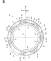
- the outer peripheral surface 70a has an exposed area AL1 and a hidden area AL2.
- Hidden area AL2 is an area hidden behind flange 75 for blower fan 111 .
- the area hidden from the blower fan 111 on the downstream side of the upstream flange 751 is the hidden area AL2.
- This hidden area AL2 extends downstream from the upstream flange 751 in the axial direction AD.
- the hidden area AL2 is on the opposite side of the blower fan 111 via the flange 75 in the axial direction AD.
- a plurality of hidden areas AL2 are arranged in the circumferential direction CD together with the upstream flange 751 .
- the exposed area AL1 is an area exposed to the blower fan 111 without being hidden behind the flange 75 .
- an exposed area that is not hidden downstream of the upstream flange 751 is the exposed area AL1.
- the exposed area AL1 is an area aligned with the hidden area AL2 in the circumferential direction CD.
- the exposed area AL1 spans two hidden areas AL2 adjacent to each other in the circumferential direction CD.
- a plurality of exposed areas AL1 are arranged in the circumferential direction CD together with hidden areas AL2.
- the exposed area AL1 corresponds to the axial alignment area
- the hidden area AL2 corresponds to the peripheral alignment area
- the upstream flange 751 corresponds to the obstruction.
- the motor fin 72 is provided in the exposed area AL1, but is not provided in the hidden area AL2.
- a plurality of motor fins 72 are provided in each of the plurality of exposed areas AL1.
- a plurality of motor fins 72 provided in one exposed area AL1 are called a motor fin group 73
- one motor fin group 73 is provided in one exposed area AL1.
- a plurality of motor fin groups 73 are arranged in the circumferential direction CD together with the exposed area AL1.
- a hidden area AL2 exists between two adjacent motor fin groups 73 in the circumferential direction CD.
- forwardly inclined fins 721 are provided on the outer peripheral surface 70a.
- the forward inclined fins 721 are inclined in the circumferential direction CD with respect to the motor axis Cm.
- the forward inclined fin 721 extends straight in a direction inclined in the circumferential direction CD with respect to the motor axis Cm. All portions of the forwardly inclined fin 721, including the upstream portion extending downstream from the fin upstream end 72a, are inclined in the circumferential direction CD with respect to the motor axis Cm.
- the forwardly inclined fin 721 as a whole is the inclined portion in this embodiment.
- the inclination angle of the forwardly inclined fins 721 is such that the forwardly inclined fins 721 extend along the swirling flow from the blower fan 111 .
- one of the pair of plate surfaces faces the upstream side, and the other faces the downstream side.
- Both of the pair of plate surfaces of the forwardly inclined fin 721 are flat surfaces. That is, the plate surface of the forwardly inclined fin 721 has a flat shape.
- the fin upstream end 72a and the fin downstream end 72b are at positions shifted in the circumferential direction CD.
- the forward inclined fin 721 is inclined so as to extend along the swirl flow by the blower fan 111 .
- the plate surface of the forward-slanted fin 721 extends along the swirling flow.
- the plate surface of the forwardly inclined fin 721 is non-parallel to the motor axis Cm. That is, in the forward inclined fin 721, the plate surface is inclined with respect to the motor axis Cm.
- the fin downstream end 72b is located downstream of the fin upstream end 72a in the circumferential direction CD.
- the forward oblique fins 721 correspond to heat radiation fins and oblique fins.
- a plurality of forwardly inclined fins 721 are arranged in the circumferential direction CD in each of the plurality of exposed areas AL1.
- the plurality of forward oblique fins 721 have the same size and shape.
- the length dimension in the axial direction AD, the plate thickness dimension, and the projection dimension from the outer peripheral surface 70a are the same for the plurality of forward-slanted fins 721 .
- the inclination angles with respect to the motor axis Cm are the same for the plurality of forwardly inclined fins 721 .
- the inclination angle of the forward inclined fins 721 is, for example, 5 degrees to 45 degrees.
- the plurality of forward-slanted fins 721 extend parallel to each other.
- the plurality of forwardly inclined fins 721 are arranged at regular intervals in the circumferential direction CD.
- each forward oblique fin 721 has the same size and shape.
- the inclination angles of the forwardly inclined fins 721 with respect to the motor axis Cm are also the same in the plurality of exposed areas AL1.
- the intervals between the plurality of forward-slanted fins 721 are also the same in the plurality of exposed regions AL1.
- the motor housing 70 accommodates the coil 63 and the coil support portion 64 .
- the coil 63 and the coil support portion 64 are included in the motor 61 and are one of the components that make up the motor 61 .
- the coil 63 and the coil support portion 64 are likely to generate heat as the motor 61 is driven.
- the coil 63 and the coil support portion 64 correspond to heat generating members.
- a coil 63 is a winding that constitutes the motor 61 .
- the coil 63 is formed in an annular shape as a whole and extends inside the motor housing 70 along the inner peripheral surface 70b.
- the coil support portion 64 is fixed to the motor housing 70 and supports the coil 63 .
- a plurality of coil support portions 64 are arranged in the circumferential direction CD along the inner peripheral surface 70b.
- the coil support portion 64 is attached to the inner peripheral surface 70b.
- the coil support portion 64 is made of a resin material or the like.
- the motor fin 72 is provided at a position aligned with the coil 63 in the radial direction RD. At least a portion of the motor fin 72 is positioned to overlap the coil 63 in the axial direction AD in the radial direction RD. The motor fin 72 is located at a position through which the coil centerline Cc passes.
- the coil centerline Cc is an imaginary straight line passing through the center of the coil 63 and extending in the radial direction RD.
- the motor fin 72 is arranged such that the coil centerline Cc passes through the center of the motor fin 72 .
- an overlapping region overlapping the coil 63 in the radial direction RD of the outer peripheral surface 70a extends annularly in the circumferential direction CD.
- This overlapping area is an area where heat from the coil 63, which is a heat generating member, is easily transmitted. That is, this overlapping area is an area corresponding to a high heat area AE1, which will be described later.
- one high heat area AE1 is configured to encircle the outer peripheral surface 70a in the circumferential direction CD.
- the inverter housing 90 has an outer peripheral surface 90a, an inner peripheral surface 90b (see FIGS. 6 and 7), and a downstream end surface 90c.
- the outer peripheral surface 90a and the inner peripheral surface 90b extend in the axial direction AD along the motor axis Cm and annularly extend in the circumferential direction CD.
- the downstream end face 90 c is the end face of the inverter housing 90 and faces the side opposite to the blower fan 111 .
- the downstream end face 90c extends in a direction perpendicular to the axial direction AD.
- the outer peripheral surface 90a includes an outer peripheral upstream end 90a1 and an outer peripheral downstream end 90a2.
- the outer peripheral upstream end 90a1 is the upstream end of the outer peripheral surface 90a.
- the outer peripheral downstream end 90a2 is the downstream end of the outer peripheral surface 90a and extends along the outer peripheral edge of the downstream end surface 90c.
- the inverter housing 90 has a housing body 91, inverter fins 92, flanges 95 and housing protrusions 96.
- the housing body 91 is formed in a tubular shape as a whole and extends along the motor axis Cm.
- the housing body 91 forms an outer peripheral surface 90a, an inner peripheral surface 90b and a downstream end surface 90c.
- the inverter fins 92 are fins provided on the outer peripheral surface 90a.
- the inverter fins 92 can release the heat of the inverter device 80 to the outside, and correspond to heat radiation fins.
- the inverter fins 92 enhance the heat radiation effect from the inverter housing 90 .
- the inverter fins 92 protrude from the outer peripheral surface 90a.
- the inverter fins 92 are provided integrally with the housing body 91 .
- the inverter fins 92 are formed in a plate shape.
- the inverter fins 92 extend radially outward from the housing body 91 and extend in the axial direction AD.
- the inverter fins 92 extend in the radial direction RD so as to overlap the radial line.
- a plurality of inverter fins 92 are arranged in the circumferential direction CD along the outer peripheral surface 90a. In two inverter fins 92 adjacent in the circumferential direction CD, their plate surfaces face each other.
- the inverter fins 92 are provided near the center of the outer peripheral surface 90a in the axial direction AD.
- the inverter fins 92 are positioned apart from both the outer peripheral upstream end 90a1 and the outer peripheral downstream end 90a2 on the outer peripheral surface 90a.
- the projection dimension of the inverter fins 92 from the outer peripheral surface 90a is larger than the projection dimension of the flange 95 from the outer peripheral surface 90a.
- the inverter fin 92 has a fin upstream end 92a and a fin downstream end 92b.
- the end on the blower fan 111 side is the fin upstream end 92a, and the opposite end is the fin downstream end 92b.
- the flange 95 is provided on the outer peripheral surface 90a and protrudes from the outer peripheral surface 90a.
- the flange 95 extends radially outward from the housing body 91 .
- the width dimension of the flange 95 is larger than the plate thickness dimension of the inverter fin 92 in the circumferential direction CD.
- Flange 95 has an upstream surface 95a.
- the upstream surface 95a is a surface of the outer surface of the flange 95 facing the blower fan 111 side.
- the upstream surface 95a extends in a direction perpendicular to the axial direction AD.
- the flange 95 tends to be an obstacle to the air flowing in the axial direction AD due to its large width and the fact that the upstream surface 95a is orthogonal to the axial direction AD.
- the flange 95 is likely to block the flow of air in the axial direction AD and corresponds to an obstruction.
- the flange 95 is, for example, a case fixing portion.
- the flange 95 is a part for fixing the inverter housing 90 to a fixed object such as the motor housing 70 .
- a fastener such as a bolt is screwed to the flange 95 .
- an upstream flange 951 and a downstream flange 952 are provided on the outer peripheral surface 90a.
- the upstream flange 951 is positioned closer to the outer peripheral upstream end 90a1 on the outer peripheral surface 90a.
- the upstream flange 951 extends, for example, in the axial direction AD from the outer peripheral upstream end 90a1 toward the outer peripheral downstream end 90a2.
- the downstream flange 952 is positioned closer to the outer peripheral downstream end 90a2 on the outer peripheral surface 90a.
- the downstream flange 952 extends, for example, from the outer peripheral downstream end 90a2 toward the outer peripheral upstream end 90a1.
- a plurality of upstream flanges 951 and downstream flanges 952 are arranged in the circumferential direction CD along the outer peripheral surface 90a.
- the housing protrusion 96 is a protrusion provided on the outer peripheral surface 90a.
- the housing protrusion 96 protrudes from the outer peripheral surface 90a.
- the housing projection 96 extends radially outward from the housing body 91 .
- the housing projecting portion 96 includes a portion projecting radially outward in accordance with the internal structure of the inverter housing 90, a connector portion for electrically connecting the inverter device 80 to an external device, and the like.
- the housing protrusion 96 shown in FIG. 6 is a large protrusion.
- a switch module 83 is accommodated in the inverter housing 90 .
- the switch module 83 is included in the drive section 81 and is one of the components that make up the drive section 81 .
- the switch module 83 tends to generate heat as the drive unit 81 is driven.
- the switch module 83 corresponds to a heat generating member.
- the switch module 83 has a switching element and an element protection section.
- a switching element is a semiconductor element that constitutes an inverter or the like.
- the element protection part is made of a resin material, and protects the switching element while covering it.
- the switch modules 83 are arranged inside the inverter housing 90 in the circumferential direction CD along the inner peripheral surface 90b. Each switch module 83 is attached to the inner peripheral surface 90b.
- a plurality of switch modules 83 are provided for a plurality of phases.
- a plurality of switch modules 83 are provided for each of the U-phase, V-phase, and W-phase.
- the switching elements of each of the plurality of switch modules 83 are connected in parallel.
- the outer peripheral surface 90a has a high heat area AE1 and a low heat area AE2.
- the high heat area AE1 is an area to which heat from the drive unit 81 is relatively easily imparted.
- the high heat area AE1 is an area that overlaps the switch module 83 in the radial direction RD.
- heat from switch module 83 is easily transferred to high heat area AE1 via housing body 71 .
- a plurality of high heat areas AE1 are arranged in the circumferential direction CD so as to match the positions of the switch modules 83 .
- the high heat area AE1 is an area bridging between the outer peripheral upstream end 90a1 and the outer peripheral downstream end 90a2 in the axial direction AD.
- the low heat area AE2 is an area to which heat from the drive unit 81 is less likely to be applied than the high heat area AE1.
- the low heat area AE2 is an area that does not overlap the switch module 83 in the radial direction RD.
- the low heat area AE2 is located farther from the switch module 83 than the high heat area AE1.
- the distance between the low heat area AE2 and the switch module 83 is smaller than the distance between the high heat area AE1 and the switch module 83 .
- the low heat area AE2 overlaps in the radial direction RD with the spaced area between two switch modules 83 adjacent in the circumferential direction CD. Heat from the switch module 83 is less likely to be transferred to the low heat area AE2 than to the high heat area AE1.
- the low heat area AE2 is located between two high heat areas AE1 adjacent to each other in the circumferential direction CD and is an area spanning these high heat areas AE1.
- a plurality of low heat areas AE2 are arranged in the circumferential direction CD.
- the low heat area AE2 is an area bridging between the outer peripheral upstream end 90a1 and the outer peripheral downstream end 90a2 in the axial direction AD.
- the low heat area AE2 is between two hidden areas AL2 adjacent in the circumferential direction CD.
- the low heat area AE2 is located at a distance in the circumferential direction CD from any of these hidden areas AL2.
- the low heat area AE2 is aligned with the exposed area AL1 in the axial direction AD and extends from the exposed area AL1 in the axial direction AD.
- the high heat area AE1 spans two adjacent exposed areas AL1 in the circumferential direction CD via the hidden area AL2.
- High heat area AE1 extends in axial direction AD from both exposed area AL1 and hidden area AL2.
- the high heat area AE1 corresponds to the first heat area
- the low heat area AE2 corresponds to the second heat area.
- a plurality of large switch modules 83 are arranged in the circumferential direction CD along the inner peripheral surface 90b.
- a plurality of switch module groups may be arranged in the circumferential direction CD along the inner peripheral surface 90b.
- the switch module group a plurality of small switch modules 83 are arranged.
- the high heat area AE1 is an area that overlaps one switch module group in the radial direction RD.
- a flange 95 is provided in the low heat area AE2.
- the flange 95 is located apart in the circumferential direction CD from both of the two high heat areas AE1 adjacent to each other in the circumferential direction CD.
- the high heat area AE1 is an area that dissipates heat more easily than the low heat area AE2.
- the inverter fins 92 are provided in the high heat area AE1, while the inverter fins 92 are not provided in the low heat area AE2.
- heat from the switch module 83 is easily radiated by the inverter fins 92 .
- the high heat area AE1 corresponds to the fin area
- the low heat area AE2 corresponds to the finless area.
- a plurality of inverter fins 92 are provided in each of the plurality of high heat areas AE1. If a plurality of inverter fins 92 provided in one high heat area AE1 are called an inverter fin group 93, one inverter fin group 93 is provided in one high heat area AE1. A plurality of inverter fin groups 93 are arranged in the circumferential direction CD together with the high heat area AE1. A low heat area AE2 exists between two adjacent inverter fin groups 93 in the circumferential direction CD. The inverter fins 92 overlap the switch module 83 in the radial direction RD with respect to the circumferential direction CD.
- parallel fins 923 are provided on the outer peripheral surface 90a.
- the parallel fins 923 extend parallel to the motor axis Cm.
- the parallel fins 923 are not inclined in the circumferential direction CD with respect to the motor axis Cm, but extend straight in the axial direction AD. Both of the pair of plate surfaces of the parallel fins 923 are flat surfaces.
- the parallel fins 923 correspond to heat radiation fins.
- a plurality of parallel fins 923 are arranged in the circumferential direction CD in each of the plurality of high heat areas AE1.
- the parallel fins 923 have the same size and shape.
- the length dimension in the axial direction AD, the plate thickness dimension, and the projection dimension from the outer peripheral surface 90a are the same for the plurality of parallel fins 923 .
- a plurality of parallel fins 923 extend parallel to each other. The plurality of parallel fins 923 are arranged at regular intervals in the circumferential direction CD.
- the parallel fins 923 have the same size and shape in the plurality of high heat areas AE1.
- the intervals between the parallel fins 923 are also the same in the high heat areas AE1.
- the inverter fins 92 are positioned to line up with the switch module 83 in the radial direction RD. At least a portion of the inverter fins 92 are positioned to overlap the switch module 83 in the axial direction AD in the radial direction RD.
- the inverter fin 92 is located at a position through which the module centerline Cp passes.
- the module centerline Cp is an imaginary straight line passing through the center of the switch module 83 and extending in the radial direction RD.
- the inverter fins 92 are arranged such that the module centerline Cp passes through the center of the inverter fins 92 .
- the inverter housing 90 also has an exposed area AL1 and a hidden area AL2 on the outer peripheral surface 90a.
- the hidden area AL ⁇ b>2 is an area hidden behind the upstream flange 951 for the blower fan 111 , for example.
- the exposed area AL1 is, for example, an area exposed to the blower fan 111 without being hidden behind the flange of the upstream flange 951 .
- the fin cover 100 has an outer peripheral surface 100a, an inner peripheral surface 100b and a cover opening 100c.
- the outer peripheral surface 100a and the inner peripheral surface 100b extend in the axial direction AD along the motor axis Cm and annularly extend in the circumferential direction CD.
- the cover openings 100c are provided at both ends of the fin cover 100 aligned in the axial direction AD.
- the inner peripheral surface 100b corresponds to the inner peripheral surface of the cover.
- the inner peripheral surface 100b of the fin cover 100 extends along the outer peripheral surfaces 70a, 90a while facing the outer peripheral surfaces 70a, 90a. Part or all of the motor fins 72 and the inverter fins 92 are in contact with the inner peripheral surface 100b. For example, the tip surfaces of the motor fins 72 and the inverter fins 92 overlap with the inner peripheral surface 100b.
- the inner peripheral surface 100b is pressed against the motor fins 72 and the inverter fins 92 by a restoring force due to elastic deformation.
- the restoring force of the fin cover 100 maintains the relative position of the fin cover 100 with respect to the motor housing 70 and the inverter housing 90 .
- FIG. 7 for convenience of illustration, gaps are shown between the inner peripheral surface 100b and the fins 72, 92, but in practice these gaps are less likely to occur.
- the shroud 120 has an outer peripheral surface 120a, an inner peripheral surface 120b and a shroud opening 120c.
- the outer peripheral surface 120a and the inner peripheral surface 120b extend in the axial direction AD along the motor axis Cm and annularly extend in the circumferential direction CD.
- the shroud openings 120c are provided at both ends of the shroud 120 aligned in the axial direction AD.
- An internal space 124 of the shroud 120 is opened in the axial direction AD by a shroud opening 120c.
- blower fan 111 is housed in internal space 124 .
- the shroud 120 and the fin cover 100 are arranged in the axial direction AD.
- the outer peripheral surfaces 100a, 120a are aligned in the axial direction AD
- the inner peripheral surfaces 100b, 120b are aligned in the axial direction AD.
- the inner peripheral surfaces 100b and 120b form a continuous surface extending continuously in the axial direction AD.
- the EDS 50 has a cover passage 104.
- a cover passage 104 is formed between the fin cover 100 and the motor housing 70 and the inverter housing 90 .
- the inner peripheral surface 100 b and the outer peripheral surfaces 70 a and 90 a are separated from each other via the motor fins 72 and the inverter fins 92 .
- This spaced portion serves as the cover passage 104 .
- the cover passage 104 is opened in the axial direction AD by a cover opening 100c.
- interior space 124 communicates with cover passage 104 .
- the hidden area AL2 closer to the fin downstream end 72b than to the fin upstream end 72a in the circumferential direction CD is referred to as the "forward hidden area.” AL2”.
- the swirling flow that has flowed along the forward inclined fins 721 easily flows into the “forward hidden area AL2”.
- the forwardly inclined fin 721 closest to the "forward hidden area AL2" in the exposed area AL1 guides the swirling flow to flow into the "forward hidden area AL2".
- the forward inclined fins 721 in the right exposed area AL1 guide the swirling flow into the "forward hidden area AL2".
- the high heat area AE1 closer to the fin downstream end 72b than the fin upstream end 72a in the circumferential direction CD is referred to as a "forward high heat area AE1".
- the swirling flow that has flowed along the forward inclined fins 721 easily flows into the "forward high heat area AE1".
- the forward inclined fin 721 in the exposed area AL1 is inclined in the circumferential direction CD with respect to the motor axis Cm so as to extend toward the "forward high heat area AE1", and the swirling flow is generated in the "forward high heat area AE1". It will guide you to flow into.
- the central high heat area AE1 is defined as a "forward high heat area AE1”
- the forward inclined fins 721 in the right exposed area AL1 guide the swirling flow into the "forward high heat area AE1".
- the swirling flow sent from the blower fan 111 circulates in the circumferential direction even after passing the forwardly slanted fins 721 due to the fact that the forwardly slanted fins 721 are slanted in the circumferential direction CD with respect to the motor axis Cm. It has become easier to continue On the other hand, since the parallel fins 923 extend parallel to the motor axis Cm, the swirling flow tends to become a parallel flow that travels parallel to the motor axis Cm by passing through the parallel fins 923 .
- the parallel fins 923 have a rectifying function of rectifying air flowing as a swirling flow so that it travels along the motor axis Cm. The swirl flow tends to become a parallel flow due to the straightening function of the parallel fins 923 .
- the parallel flow rectified by the parallel fins 923 is discharged to the outside from the cover passage 104 toward the downstream side as a parallel flow.
- forwardly inclined fins 721 inclined in the circumferential direction CD with respect to the motor axis Cm are provided on the outer peripheral surface 70a.
- the forwardly inclined fins 721 can guide the air flowing along the outer peripheral surface 70 a so as to enhance the cooling effect for the EDS 50 . Therefore, even if the number and size of the motor fins 72 and the inverter fins 92 are limited so that the EDS 50 does not become too heavy for the eVTOL 10, the downwardly inclined fins 721 can prevent the cooling effect of the EDS 50 from being lowered. . Therefore, both the improvement of the cooling effect and the weight reduction of the EDS 50 can be achieved by the forwardly inclined fins 721 . In this way, the EDS 50 and the EDS unit 130 suitable for mounting on the eVTOL 10 can be realized by the forward inclined fins 721 .
- the motor fins 72 in a configuration in which the motor fins 72 do not include the forwardly inclined fins 721, the motor fins 72 inclined so as to extend along the swirl flow by the blower fan 111 do not exist.
- the swirling flow that reaches the motor fins 72 is disturbed, and the pressure loss of the swirling flow flowing between the plurality of motor fins 72 increases. If the pressure loss increases in this way, there is concern that the amount of swirling air flowing between the motor fins 72 will be insufficient, and the heat dissipation effect of the motor fins 72 will be reduced.
- the amount of air flowing between the inverter fins 92 arranged downstream of the motor fins 72 is also reduced, and there is concern that the heat dissipation effect of the inverter fins 92 is also reduced.
- the forwardly inclined fins 721 are inclined so as to extend along the swirling flow generated by the blower fan 111 .
- the forwardly inclined fins 721 can guide the swirling flow so that the swirling flow is not disturbed. Therefore, the swirling flow reaching the forwardly inclined fins 721 is less likely to be disturbed.
- the pressure loss of the swirling flow flowing between the plurality of forwardly inclined fins 721 is less likely to increase, and the shortage of air volume of the swirling flow flowing between the plurality of forwardly inclined fins 721 is less likely to occur. Therefore, the air volume of the swirl flow flowing between the plurality of forwardly inclined fins 721 can be sufficiently secured for cooling the motor device 60 . In this manner, the heat dissipation effect of the forwardly inclined fins 721 can be enhanced.
- the fin cover 100 is attached to the motor housing 70 and the inverter housing 90 so as to cover the motor fins 72 and the inverter fins 92 from the outer peripheral side.
- the swirling flow generated by the blower fan 111 flows through the cover passage 104 formed between the motor housing 70 and the inverter housing 90 and the fin cover 100 . Therefore, the fin cover 100 can prevent the swirling flow from flowing radially outside the motor fins 72 and the inverter fins 92 . Therefore, the fin cover 100 can prevent the amount of air passing through the motor fins 72 and the inverter fins 92 from decreasing and the cooling effect from decreasing.
- the forwardly inclined fins 721 suppress an increase in the pressure loss of the swirling flow. Therefore, even if the pressure loss in the cover passage 104 increases, the forwardly inclined fins 721 suppress the increase in the pressure loss, so that the pressure loss does not excessively increase.
- the swirling flow generated by the blower fan 111 is not guided in the circumferential direction CD and is less likely to flow into the hidden area AL2.
- the swirling flow tends to flow into the exposed area AL1 but less likely to flow into the hidden area AL2.
- the air volume in the hidden area AL2 tends to be smaller than the air volume in the exposed area AL1.
- the heat generation mode tends to be uniform in the circumferential direction CD due to the fact that the coil 63 as the heat generating member extends annularly in the circumferential direction CD.
- the heat dissipation effect tends to be lower in the hidden area AL2 than in the exposed area AL1. tend to be uniform.
- the forwardly inclined fins 721 are inclined so as to guide the swirling flow from the exposed area AL1 to the hidden area AL2.
- the swirling flow that has flowed into the exposed area AL1 flows along the forwardly inclined fins 721, thereby making it easier to flow into the hidden area AL2. Therefore, it is difficult for the air volume in the hidden area AL2 to be less than the air volume in the exposed area AL1. Therefore, it is possible to prevent uneven heat distribution in the circumferential direction CD in the motor housing 70 .
- a cooling effect can be applied to the entire circumferential direction CD in the motor housing 70 .
- the forwardly inclined fins 721 are inclined so as to guide the swirling flow to the high heat area AE1.
- the swirling flow flows along the forward-slanted fins 721, making it easier to flow into the high heat area AE1, so that the high heat area AE1 tends to increase. Therefore, in the high heat area AE1, which is the area near the switch module 83 out of the high heat area AE1 and the low heat area AE2, the downwardly inclined fins 721 can prevent the cooling effect from deteriorating due to insufficient air volume. Therefore, in the inverter housing 90, the forwardly inclined fins 721 can prevent the temperature of a part such as the high heat area AE1 from excessively rising.
- the forward-slanted fin 721 is provided at a position separated from the high heat area AE1 on the upstream side of the swirling flow, and is slanted so as to extend into the high heat area AE1. Therefore, both a configuration in which the swirling flow easily flows along the forwardly inclined fins 721 and a configuration in which the swirling flow flowing along the forwardly inclined fins 721 easily reaches the high heat area AE1 can be realized.
- the high heat area AE1 is an area that overlaps the switch module 83 in the circumferential direction CD
- the low heat area AE2 is an area that does not overlap the switch module 83 in the circumferential direction CD.
- the heat applied to the low heat area AE2 tends to be less than the heat applied to the high heat area AE1. Therefore, by guiding the swirling flow to the high heat area AE1 with the forwardly inclined fins 721, even if the air volume in the low heat area AE2 decreases, the temperature in the low heat area AE2 is unlikely to rise excessively. there is Therefore, even if the air volume in the low heat area AE2 is less than the air volume in the high heat area AE1, the inverter housing 90 can enhance the cooling effect in the entire circumferential direction CD.
- the inverter fins 92 are provided in the high heat area AE1, while the inverter fins 92 are not provided in the low heat area AE2.
- the upstream portion extending downstream from the fin upstream end 72a is inclined with respect to the motor axis Cm.
- the swirling flow that reaches the forwardly inclined fins 721 easily flows along the upstream portion of the forwardly inclined fins 721 . Therefore, the upstream portion of the forwardly inclined fin 721 can suppress the disturbance of the swirling flow that has reached the forwardly inclined fin 721 . Therefore, an increase in the pressure loss of the swirling flow flowing between the forwardly slanted fins 721 can be suppressed by the upstream portion of the forwardly slanted fins 721 .
- the parallel fins 923 are provided downstream of the forwardly inclined fins 721 .
- the swirling flow is easily rectified by the parallel fins 923 to become a parallel flow.
- the parallel flow of the air discharged downstream from the EDS 50 makes it difficult for the thrust and lift generated by the eVTOL 10 to decrease.
- the component flowing in the circumferential direction CD tends to be smaller than when it is a swirl flow.
- the EDS 50 suitable for mounting on the eVTOL 10 can be realized from the viewpoint of properly managing the flight state of the eVTOL 10 as well.
- the tip surfaces of the motor fins 72 and the inverter fins 92 overlap the inner peripheral surface 100b. Therefore, the air from the blower fan 111 easily flows along the plate surfaces of the motor fins 72 and the inverter fins 92 . Therefore, the cooling effect exhibited by the motor fins 72 and the inverter fins 92 can be further enhanced.
- Radiation fins such as the motor fins 72 may be provided in the hidden area AL2.
- Radiation fins such as the motor fins 72 may be provided in the hidden area AL2.
- the forward oblique fin 721 is provided in the hidden area AL2.
- a forward inclined fin 721 is provided in each of the exposed area AL1 and the hidden area AL2.
- One of the forwardly inclined fins 721 out of the plurality of forwardly inclined fins 721 is in a state of bridging between the exposed area AL1 and the hidden area AL2.
- the forwardly inclined fin 721 is arranged at a position straddling the boundary between the exposed area AL1 and the hidden area AL2 in the circumferential direction CD.
- the fin upstream end 72a is located in the exposed area AL1
- the fin downstream end 72b is located in the hidden area AL2.
- the fin downstream end 72b is located on the opposite side of the blower fan 111 via the upstream flange 751 in the axial direction AD.
- the fin upstream end 72a is located in the exposed area AL1
- the fin downstream end 72b is located in the hidden area AL2.
- the swirling flow traveling along the forwardly inclined fins 721 in the exposed area AL1 reaches the fin downstream end 72b and flows into the hidden area AL2. Therefore, by arranging one forward-inclined fin 721 at a position straddling the boundary between the exposed area AL1 and the hidden area AL2, the cooling effect of the hidden area AL2 can be enhanced.
- the inclination angles of the inclined fins such as the forward inclined fins 721 with respect to the motor axis Cm may not be uniform among the plurality of inclined fins.
- the plurality of motor fins 72 in the first embodiment includes reversely inclined fins 722 .
- the plurality of motor fins 72 includes both forward-slanted fins 721 and reverse-slanted fins 722 .
- the reversely inclined fin 722 is a fin that is inclined in the circumferential direction CD with respect to the motor axis Cm in a direction opposite to that of the forwardly inclined fin 721 .
- one of the pair of plate surfaces faces the blower fan 111 side and the other faces the inverter device 80 side.
- the surface of the reversely inclined fin 722 facing the fan 111 and the surface of the forwardly inclined fin 721 facing the fan 111 are opposite to each other in the circumferential direction CD.
- the reverse inclined fins 722 correspond to heat radiation fins and inclined fins.
- the reverse inclined fins 722 extend straight in a direction inclined in the circumferential direction CD with respect to the motor axis Cm.
- the whole is an inclined portion.
- the plate surface of the reverse inclined fin 722 has a flat shape.
- the plate surface is non-parallel to the motor axis Cm. That is, the plate surface of the reverse inclined fin 722 is inclined with respect to the motor axis Cm.
- the direction in which the reversely inclined fins 722 guide the swirling flow in the circumferential direction CD is opposite to that of the forwardly inclined fins 721 . Therefore, in one exposed area AL1 of two exposed areas AL1 adjacent to each other with the hidden area AL2 interposed therebetween in the circumferential direction CD, the motor fin 72 closest to the hidden area AL2 is the forward inclined fin 721 . In the other exposed area AL ⁇ b>1 , the motor fin 72 closest to the hidden area AL ⁇ b>2 is the reverse inclined fin 722 . In this configuration, a swirling flow is guided from one exposed area AL1 to the hidden area AL2 by the forwardly inclined fins 721, and a swirling flow is guided to the hidden area AL2 by the reversely inclined fins 722 from the other exposed area AL1. By guiding the swirling flow from both of the two exposed areas AL1 to one hidden area AL2 in this way, the air volume in the hidden area AL2 increases, and the cooling effect of the hidden area AL2 can be enhanced.
- the inclination angles with respect to the motor axis Cm are different for the plurality of forwardly inclined fins 721 provided in one exposed area AL1.
- the inclination angle gradually increases from one side toward the other side in the circumferential direction CD.
- the heat radiation fins such as the motor fins 72 may be curved so as to expand in the plate thickness direction of the heat radiation fins.
- the forward inclined fin 721 is curved so as to bulge in the axial direction AD.
- each of the plurality of forwardly inclined fins 721 is curved so as to swell toward the upstream side in the axial direction AD.
- These forwardly inclined fins 721 are curved so as to be inclined in a direction extending along the swirling flow as a whole.
- the inclination angle with respect to the motor axis Cm gradually decreases from the fin upstream end 72a toward the fin downstream end 72b.
- the forwardly inclined fins 721 are curved so as to swell toward the upstream side in the axial direction AD, the direction of the swirling flow flowing along the forwardly inclined fins 721 changes from the fin upstream end 72a to the fin downstream end 72b. gradually change towards When the airflow passing through the forwardly inclined fins 721 changes from a swirling flow to a parallel flow, the forwardly inclined fins 721 have a straightening function.
- the forwardly inclined fin 721 as a whole is inclined with respect to the motor axis Cm, and the forwardly inclined fin 721 as a whole forms an inclined portion.
- the motor fin groups 73 may not be arranged in plural in the circumferential direction CD. In this modification, one motor fin group 73 extends annularly around the outer peripheral surface 70a. For example, as shown in FIGS. 10 and 11, a plurality of forwardly inclined fins 721 are provided in both the exposed area AL1 and the hidden area AL2.
- the lengths in the axial direction AD of the plurality of radiation fins may not be uniform.
- the lengths in the axial direction AD are different between the plurality of forward-inclined fins 721 in the first embodiment.
- the length dimension in the axial direction AD gradually decreases from one side to the other side in the circumferential direction CD.
- the forwardly inclined fins 721 in the hidden area AL2 may be shorter in the axial direction AD than the forwardly inclined fins 721 in the exposed area AL1. .
- the heat radiation fins such as the motor fins 72 and the heat generating members such as the coils 63 may be provided at positions shifted in the axial direction AD.
- the motor fin 72 is shifted in the axial direction AD with respect to the coil 63 .
- the motor fin 72 is positioned closer to the inverter device 80 with respect to the coil centerline Cc.
- the inverter fins 92 may be displaced in the axial direction AD with respect to the switch module 83 .
- the fin cover 100 has a cover guide portion. Configurations, actions, and effects not specifically described in the second embodiment are the same as those in the first embodiment. In the second embodiment, the points different from the first embodiment will be mainly described.
- the fin cover 100 has a cover main body 101 and cover fins 102.
- the cover main body 101 is formed in a tubular shape as a whole and extends along the motor axis Cm.
- the cover main body 101 forms an outer peripheral surface 100a, an inner peripheral surface 100b and a cover opening 100c.
- the cover fins 102 are fins provided on the inner peripheral surface 100b.
- the cover fins 102 protrude from the inner peripheral surface 100b.
- the cover fins 102 are provided integrally with the cover main body 101 .
- the cover fins 102 are formed in a plate shape.
- the cover fins 102 extend radially inward from the cover body 101 and extend in the axial direction AD.
- the cover fins 102 extend in the radial direction RD so as to overlap the radial line.
- a plurality of cover fins 102 are arranged in the circumferential direction CD along the inner peripheral surface 100b.
- the plate surfaces of two cover fins 102 adjacent in the circumferential direction CD face each other.
- the cover fin 102 has a fin upstream end 102a and a fin downstream end 102b.
- the end on the blower fan 111 side is the fin upstream end 102a, and the opposite end is the fin downstream end 102b.
- the cover fins 102 are provided upstream of the motor fins 72 in the axial direction AD.
- the cover fin 102 is between the outer peripheral upstream end 70a1 and the motor fin 72 in the axial direction AD.
- the plurality of cover fins 102 include cover fins 102 in contact with the motor fins 72 and cover fins 102 spaced apart from the motor fins 72 in the axial direction AD.
- the plurality of cover fins 102 include cover fins 102 extending downstream from the outer peripheral upstream end 70a1 and cover fins 102 located downstream from the outer peripheral upstream end 70a1.
- the cover fins 102 are inclined in the circumferential direction CD with respect to the motor axis Cm.
- the cover fins 102 are curved so as to expand in the axial direction AD. All of the plurality of cover fins 102 are curved so as to swell toward the upstream side in the axial direction AD. These cover fins 102 as a whole are curved so as to be inclined in a direction extending along the swirling flow.
- the inclination angle with respect to the motor axis Cm gradually decreases from the fin upstream end 102a toward the fin downstream end 102b.
- the direction of the swirling flow flowing along the cover fins 102 gradually changes from the fin upstream end 102a toward the fin downstream end 92b.
- the cover fins 102 are inclined with respect to the motor axis Cm so as to extend toward the motor fins 72 .
- the cover fins 102 extend downstream toward the motor fins 72 .
- the cover fins 102 guide the swirling flow flowing along the cover fins 102 toward the motor fins 72 .
- the cover fins 102 correspond to cover guides.
- the cover fin 102 is provided at a position overlapping the exposed area AL1 in the radial direction RD.
- a plurality of cover fins 102 are provided for each of the plurality of exposed areas AL1. If a plurality of cover fins 102 provided for one exposed area AL1 are called a cover fin group 103, one cover fin group 103 is provided for one exposed area AL1.
- a plurality of cover fin groups 103 are arranged in the circumferential direction CD together with the exposed area AL1.
- the cover fins 102 are in contact with the outer peripheral surface 70a.
- the tip surface of the cover fin 102 overlaps the outer peripheral surface 70a.
- the tip surfaces of the cover fins 102 are pressed against the outer peripheral surface 70a by a restoring force due to elastic deformation.
- a gap is shown between the outer peripheral surface 70a and the cover fins 102, but in practice this gap is less likely to occur.
- At least one cover fin 102 is in contact with the motor fin 72 in this embodiment.
- the motor fin 72 and the cover fin 102 that are in contact with each other are in contact with each other such that the fin upstream end 72a and the fin downstream end 102b overlap in the axial direction AD.
- These motor fins 72 and cover fins 102 are in a state in which the cover fins 102 extend upstream from the motor fins 72 .
- the plate surface of the cover fin 102 and the plate surface of the motor fin 72 are surfaces that extend continuously in the axial direction AD.
- the step of attaching the fin cover 100 to the motor housing 70 and the inverter housing 90 is performed.
- the operator accommodates the motor housing 70 and the inverter housing 90 inside the fin cover 100 by inserting the upstream end face 70c into the inside of the cover opening 100c.
- the fin cover 100 is moved relative to the motor housing 70 in the axial direction AD until the fin upstream end 72a contacts the fin downstream end 102b.
- the manufacturing process is included in the manufacturing method for manufacturing the EDS 50 .
- parallel fins 723 are included in the plurality of motor fins 72 .
- the parallel fins 723 extend parallel to the motor axis Cm.
- the parallel fins 723 are not inclined in the circumferential direction CD with respect to the motor axis Cm, but extend linearly in the axial direction AD. Both of the pair of plate surfaces of the parallel fins 723 are flat surfaces.
- the parallel fins 723 correspond to heat radiation fins.
- each of the plurality of motor fins 72 has an inclination angle with respect to the motor axis Cm, a length dimension in the circumferential direction CD, and a length dimension in the circumferential direction CD so that the cooling effect of the motor device 60 is enhanced.
- the degree of curvature is set.
- the inclination angle of the motor fin 72 with respect to the motor axis Cm increases and decreases in one motor fin 72 from the fin upstream end 72a toward the fin downstream end 72b.
- the inclination angles of the motor fins 72 with respect to the motor axis Cm are different among the plurality of motor fins 72 .
- the motor fins 72 have different length dimensions in the axial direction AD among the plurality of motor fins 72 .
- the motor fins 72 have different degrees of bending in the circumferential direction CD.
- the interval between two motor fins 72 adjacent to each other in the circumferential direction CD does not have to be uniform between the plurality of motor fins 72 . If the cooling effect of the motor device 60 is improved, it is preferable that the intervals between the motor fins 72 are not made uniform.
- each of the plurality of motor fins 72 and the plurality of cover fins 102 are set so that the swirling flow passes through the motor fins 72 and becomes a parallel flow.
- the motor fins 72 and the cover fins 102 as a whole exert a rectifying function, so that the air flowing downstream from the motor fins 72 toward the parallel fins 923 tends to flow in parallel.
- the parallel flow easily flows along the parallel fins 923, the air flow passing through the inverter fins 92 is less likely to be disturbed. Therefore, the amount of air passing through the inverter fins 92 tends to increase, and the heat dissipation effect of the inverter fins 92 tends to improve.
- the air from the blower fan 111 is guided to the forwardly inclined fins 721 by the cover fins 102 .
- the cover fins 102 can increase the amount of air passing through the forward-slanted fins 721 . Therefore, the cooling effect exhibited by the forwardly inclined fins 721 can be further enhanced by the cover fins 102 . Further, by replacing a portion of the sloped portion shape of the forward-slanted fin 721 with the cover fin 102, the weight of the EDS 50 can be reduced.
- the cover fins 102 may not be curved in the circumferential direction CD.
- the cover fins 102 extend straight in the second embodiment.
- the cover fins 102 extend straight in a direction inclined in the circumferential direction CD with respect to the motor axis Cm. All portions of the cover fin 102, including the upstream portion extending downstream from the fin upstream end 102a, are inclined in the circumferential direction CD with respect to the motor axis Cm.
- the inclination angle of the cover fins 102 with respect to the motor axis Cm is larger than the inclination angle of the forwardly inclined fins 721 with respect to the motor axis Cm.
- the cover fins 102 may extend parallel to the motor axis Cm.
- the plurality of cover fins 102 may have the same size and shape, or may have different sizes.
- the plurality of cover fins 102 may or may not be uniformly spaced in the axial direction AD. Further, the cover fins 102 may be curved so as to swell toward the upstream side in the axial direction AD.
- shroud 120 has a shroud guide. Configurations, actions, and effects that are not specifically described in the third embodiment are the same as those in the first embodiment. In the third embodiment, the points different from the first embodiment will be mainly described.
- the shroud 120 has a shroud body 121 and shroud fins 122. As shown in FIGS. The shroud body 121 is generally cylindrical and extends along the motor axis Cm. The shroud body 121 forms an outer peripheral surface 120a, an inner peripheral surface 120b and a shroud opening 120c.
- the shroud fins 122 are fins provided on the inner peripheral surface 120b.
- the shroud fins 122 protrude from the inner peripheral surface 120b.
- the shroud fins 122 are provided integrally with the shroud body 121 .
- Shroud fin 122 is formed in a plate shape.
- the shroud fins 122 extend radially inward from the shroud body 121 and extend in the axial direction AD.
- the shroud fins 122 extend in the radial direction RD so as to overlap the radial line.
- the projection dimension of the shroud fins 122 from the inner peripheral surface 120b is substantially the same as the projection dimension of the motor fins 72 from the outer peripheral surface 70a.
- a plurality of shroud fins 122 are arranged in the circumferential direction CD along the inner peripheral surface 120b.
- the plate surfaces of two shroud fins 122 adjacent in the circumferential direction CD face each other.
- the shroud fin 122 has a fin upstream end 122a and a fin downstream end 122b.
- the end on the blower fan 111 side is the fin upstream end 122a, and the opposite end is the fin downstream end 122b.
- the shroud fins 122 are provided upstream of the motor fins 72 in the axial direction AD.
- the shroud fins 122 extend upstream from the downstream shroud opening 120c.
- the shroud fins 122 are inclined in the circumferential direction CD with respect to the motor axis Cm.
- the shroud fins 122 are bent to expand in the axial direction AD. All of the plurality of shroud fins 122 are curved so as to swell toward the upstream side in the axial direction AD. These shroud fins 122 are curved so as to be inclined in a direction extending along the swirling flow as a whole.
- the inclination angle with respect to the motor axis Cm gradually decreases from the fin upstream end 122a toward the fin downstream end 122b.
- the shroud fins 122 are curved so as to swell toward the upstream side in the axial direction AD, and thus easily change the direction of the swirling flow.
- the shroud fins 122 are inclined with respect to the motor axis Cm so as to extend toward the motor fins 72 .
- Shroud fins 122 extend downstream toward motor fins 72 .
- the shroud fins 122 guide the swirling flow flowing along the shroud fins 122 toward the motor fins 72 .
- the shroud fins 122 correspond to shroud guides.
- the shroud fins 122 are arranged in the exposed area AL1 in the axial direction AD.
- a plurality of shroud fins 122 are provided for each of the plurality of exposed areas AL1.
- a plurality of shroud fins 122 provided for one exposed area AL1 is called a shroud fin group 123
- one shroud fin group 123 is provided for one exposed area AL1.
- a plurality of shroud fin groups 123 are arranged in the circumferential direction CD together with the exposed area AL1.
- the air from the blower fan 111 is guided to the forward inclined fins 721 by the shroud fins 122 .
- the shroud fins 122 can increase the amount of air passing through the forward sloping fins 721 . Therefore, the shroud fins 122 can further enhance the cooling effect exhibited by the forwardly inclined fins 721 .
- the blower fan 111 is provided upstream of the EDS 50 .
- the blower fan 111 is provided downstream of the EDS 50 .
- Configurations, functions, and effects that are not specifically described in the fourth embodiment are the same as those in the first embodiment.
- the points different from the first embodiment will be mainly described.
- the blower fan 111 is provided on the downstream end surface 90c side.
- the blower fan 111 blows air in the axial direction AD toward the side opposite to the EDS 50 .
- a swirling flow is generated not only on the downstream side of the blower fan 111 but also on the upstream side of the blower fan 111 .
- the swirling flow generated on the upstream side of the blower fan 111 advances toward the blower fan 111 in the axial direction AD. This swirling flow is generated by the air sucked into the blower fan 111 .
- the blower fan 111 sucks in the cooling air for cooling the EDS 50 under negative pressure.
- the side of the blower fan 111 is the downstream side of the EDS 50 .
- forwardly inclined fins 921 are provided on the outer peripheral surface 90a.
- the forward inclined fins 921 are inclined in the circumferential direction CD with respect to the motor axis Cm.
- the forward inclined fin 921 extends straight in a direction inclined in the circumferential direction CD with respect to the motor axis Cm. All portions of the forwardly inclined fin 921, including the upstream portion extending downstream from the fin upstream end 92a, are inclined in the circumferential direction CD with respect to the motor axis Cm.
- the plurality of inverter fins 92 may include reversely inclined fins.
- the reverse-tilt fin is a fin whose tilt direction with respect to the motor axis Cm is opposite to that of the forward-tilt fin 921 .
- the inclination angle of the forwardly slanted fins 921 is such that the forwardly slanted fins 921 extend along the swirling flow proceeding toward the blower fan 111 .
- the forward inclined fin 921 one of the pair of plate surfaces faces the upstream side and the other faces the downstream side. Both of the pair of plate surfaces of the forwardly inclined fin 921 are flat surfaces.
- the fin upstream end 92a and the fin downstream end 92b are offset in the circumferential direction CD.
- the forward inclined fins 921 are inclined so as to extend along the swirl flow by the blower fan 111 .
- the plate surface of the forwardly inclined fin 921 extends along the swirling flow.
- the forward oblique fins 921 correspond to heat radiation fins and oblique fins.
- an exposed area AL1 and a hidden area AL2 are set on the outer peripheral surface 90a.
- the hidden area AL2 is an area hidden behind the flange 95 for the blower fan 111 .
- the area hidden from the blower fan 111 on the upstream side of the downstream flange 952 is the hidden area AL2.
- This hidden area AL2 extends upstream from the downstream flange 952 in the axial direction AD.
- a plurality of hidden areas AL2 are arranged in the circumferential direction CD together with the downstream flange 952 .
- the exposed area AL1 is an area exposed to the blower fan 111 without being hidden behind the flange 95 .
- the exposed area AL1 is an exposed area that is not hidden on the upstream side of the downstream flange 952 for the blower fan.
- the exposed area AL1 corresponds to the axial alignment area
- the hidden area AL2 corresponds to the peripheral alignment area
- the downstream flange 952 corresponds to the obstruction.
- a plurality of forwardly inclined fins 921 are arranged in the circumferential direction CD in each of the plurality of exposed areas AL1.
- the plurality of forward oblique fins 921 have the same size and shape.
- the length dimension in the axial direction AD, the plate thickness dimension, and the projection dimension from the outer peripheral surface 90a are the same for the plurality of forward-slanted fins 921 .
- the inclination angles with respect to the motor axis Cm are the same for the plurality of forwardly inclined fins 921 .
- the inclination angle of the forward inclined fins 921 is, for example, 5 degrees to 20 degrees.
- the plurality of forward-slanted fins 921 extend parallel to each other.
- the plurality of forwardly inclined fins 921 are arranged at regular intervals in the circumferential direction CD.
- each forward oblique fin 921 has the same size and shape.
- the inclination angles of the forwardly inclined fins 921 with respect to the motor axis Cm are also the same in the plurality of exposed areas AL1.
- the intervals between the plurality of forward-slanted fins 921 are also the same in the plurality of exposed areas AL1.
- the hidden area AL2 closer to the fin upstream end 92a than to the fin downstream end 92b in the circumferential direction CD is referred to as the "forward hidden area”.
- AL2 Since the air flows along the forwardly inclined fins 921, the air sucked by the blower fan 111 easily passes through the "forwardly hidden area AL2.”
- the forwardly inclined fin 721 closest to the "forward hidden area AL2" in the exposed area AL1 guides the air from the "forward hidden area AL2" to the blower fan 111.
- FIG. In FIG. 18, if the hidden area AL2 on the right side is referred to as the "forward hidden area AL2", the forward inclined fins 921 in the central exposed area AL1 guide the air from the "forward hidden area AL2" to the blower fan 111.
- forwardly inclined fins 921 inclined in the circumferential direction CD with respect to the motor axis Cm are provided on the outer peripheral surface 90a.
- the forwardly inclined fins 921 can guide the air flowing along the outer peripheral surface 90 a so as to enhance the cooling effect for the EDS 50 . Therefore, even if the number and size of the motor fins 72 and the inverter fins 92 are limited so that the EDS 50 does not become too heavy for the eVTOL 10, the downwardly inclined fins 921 can prevent the cooling effect of the EDS 50 from being lowered. . Therefore, both the improvement of the cooling effect and the weight reduction of the EDS 50 can be achieved by the forwardly inclined fins 921 . In this way, the EDS 50 and the EDS unit 130 suitable for mounting on the eVTOL 10 can be realized by the forward inclined fins 921 .
- the motor housing 70 has a guide. Configurations, functions, and effects that are not specifically described in the fifth embodiment are the same as those in the first embodiment. In the fifth embodiment, differences from the first embodiment will be mainly described.
- the motor housing 70 has housing protrusions 76 and motor guide plates 77 .
- the housing protrusion 76 is a protrusion provided on the outer peripheral surface 70a.
- the housing protrusion 76 protrudes from the outer peripheral surface 70a.
- the housing projection 76 extends radially outward from the housing main body 71 .
- the housing projecting portion 76 includes a portion projecting radially outward in accordance with the internal structure of the motor housing 70, a connector portion for electrically connecting the motor device 60 to an external device, and the like.
- the housing projections 76 shown in FIG. 20 are small projections.
- the width dimension of the housing protrusion 76 in the circumferential direction CD is larger than the plate thickness dimension of the motor fin 72 .
- the housing projection 76 has an upstream surface 76a.
- the upstream surface 76a is a surface of the outer surface of the housing protrusion 76 facing the upstream side.
- the upstream surface 76a extends in a direction orthogonal to the axial direction AD.
- the housing protrusion 76 tends to become an obstacle to the air flowing in the axial direction AD due to its large width and the fact that the upstream surface 76a is perpendicular to the axial direction AD.
- the housing projecting portion 76 tends to obstruct the flow of air in the axial direction AD, and corresponds to an obstruction.
- the housing protrusions 76 are aligned with the flange 75 in the circumferential direction CD.
- the housing projection 76 is between two upstream flanges 751 adjacent in the circumferential direction CD.
- the housing protrusion 76 is positioned closer to the outer peripheral upstream end 70a1 than to the outer peripheral downstream end 70a2 in the axial direction AD.
- the housing projecting portion 76 is positioned away from the outer peripheral upstream end 70a1 toward the outer peripheral downstream end 70a2.
- the plurality of hidden areas AL2 include hidden areas AL2 hidden behind the housing protrusion 76 from the blower fan 111 .
- the hidden area AL2 extends downstream from the housing protrusion 76 in the axial direction AD.
- the motor guide plate 77 is provided on the outer peripheral surface 70a.
- the motor guide plate 77 protrudes from the outer peripheral surface 70a.
- the motor guide plate 77 is provided integrally with the housing body 71 .
- the motor guide plate 77 is formed in a plate shape as a whole.
- the motor guide plate 77 is curved so as to swell toward the upstream side in the axial direction AD.
- the motor guide plate 77 is curved such that the central portion swells toward the upstream side.
- a plurality of motor guide plates 77 are arranged in the circumferential direction CD.
- the motor guide plate 77 guides the air from the blower fan 111 in the circumferential direction CD so as to flow toward the motor fins 72 .
- the motor guide plate 77 corresponds to the guide portion and the housing guide portion.
- the projection dimension of the motor guide plate 77 from the outer peripheral surface 70a is larger than the projection dimension of the flange 75 from the outer peripheral surface 70a.
- the motor guide plate 77 and the motor fin 72 have substantially the same projection dimension from the outer peripheral surface 70a.
- the motor guide plate 77 is in contact with the inner peripheral surface 100b.
- the tip surface of the motor guide plate 77 overlaps the inner peripheral surface 100b.
- the inner peripheral surface 100b is pressed against the motor guide plate 77 by a restoring force due to elastic deformation.
- a gap is shown between the inner peripheral surface 100b and the motor guide plate 77 for convenience of illustration, but in practice this gap is less likely to occur.
- the motor guide plate 77 has a guide top portion 77a, a guide end portion 77b, a guide outer surface 77c and a guide inner surface 77d.
- the motor guide plate 77 has a pair of plate surfaces, and both of these plate surfaces are convexly curved so as to swell toward the upstream side in the axial direction AD.
- the outer plate surface of the pair of plate surfaces is the guide outer surface 77c
- the inner plate surface is the guide inner surface 77d.
- the guiding outer surface 77c faces upstream in the axial direction AD.
- the guiding outer surface 77c is inclined in the circumferential direction CD with respect to the motor axis Cm.
- the guide inner surface 77d faces the downstream side in the axial direction AD.
- the guide outer surface 77c corresponds to the guide surface.
- the guiding top portion 77a is the most upstream part of the guiding outer surface 77c.
- the guide end portion 77b is the downstream end portion of the guide outer surface 77c, and is included in the guide outer surface 77c.
- the pair of guide ends 77b are arranged in the circumferential direction CD via the guide top 77a.
- the guiding end portion 77b is located downstream from the guiding top portion 77a in the axial direction AD.
- a guide end 77 b is included at the downstream end of the motor guide plate 77 .
- the inclination angle of the guide outer surface 77c with respect to the motor axis Cm gradually decreases from the guide top portion 77a toward the guide end portion 77b.
- an exposed guide plate 771 and a high heat guide plate 772 are provided on the outer peripheral surface 70a.
- the exposed guide plate 771 shown in FIGS. 20 and 21 guides the air flowing toward the hidden area AL2 in the axial direction AD in the circumferential direction CD so as to flow toward the exposed area AL1.
- the exposed guide plate 771 is provided on the upstream side of the hidden area AL2 and extends along the outer peripheral surface 70a toward the exposed area AL1.
- the exposed guide plate 771 protrudes from the hidden area AL2 in the circumferential direction CD.
- the exposure guide plate 771 spans two adjacent exposed areas AL1 via the hidden area AL2 in the circumferential direction CD.
- the exposure guide plate 771 is positioned to overlap the hidden area AL2 in the axial direction AD.
- the exposure guide plate 771 is arranged in the hidden area AL2 in the axial direction AD by being provided in the hidden area AL2.
- the guide apex 77a overlaps the hidden area AL2 in the axial direction AD.
- the guide end portion 77b is not positioned to overlap the hidden area AL2 in the axial direction AD, but is spaced apart from the hidden area AL2 in the circumferential direction CD.
- the exposed guide plate 771 is in a state of being spanned over the motor fins 72 of the two exposed areas AL1.
- the two motor fins 72 over which the exposed guide plate 771 spans are adjacent in the circumferential direction CD via the hidden area AL2.
- the guide outer surface 77 c is in a state where it spans over the two motor fins 72 .
- a pair of ends of the exposed guide plate 771 are positioned close to each of the two motor fins 72 and are not connected to the motor fins 72 .
- the exposed guide plate 771 is separated in both the axial direction AD and the circumferential direction CD from the two motor fins 72 adjacent to each other via the hidden area AL2 in the circumferential direction CD.
- the guiding end portion 77b is located upstream from the fin upstream end 72a.
- the guide end portion 77b is positioned away from the fin upstream end 72a toward the housing projection portion 76 side.
- the exposed guide plate 771 is provided on the upstream side of the housing protrusion 76 .
- the exposed guide plate 771 is positioned to line up with the housing protrusion 76 in the axial direction AD.
- the exposed guide plate 771 covers the housing protrusion 76 from the upstream side.
- the guide inner surface 77d faces the housing protrusion 76 side.
- the guide inner surface 77d is spaced upstream from the housing protrusion 76.
- At least a portion of the housing protrusion 76 is inserted inside the exposed guide plate 771 .
- the width dimension of the exposed guide plate 771 is larger than the width dimension of the housing protrusion 76 in the circumferential direction CD.
- the exposed guide plate 771 extends downstream from the outer peripheral upstream end 70a1.
- the exposed guide plate 771 may be provided at a position spaced downstream from the outer peripheral upstream end 70a1. Also, the exposed guide plate 771 may be provided at a position protruding upstream from the outer peripheral upstream end 70a1. Also, the exposed area AL1 corresponds to the first area, and the hidden area AL2 corresponds to the second area.
- the high heat induction plate 772 shown in FIGS. 20 and 23 guides the air flowing toward the low heat area AE2 in the axial direction AD in the circumferential direction CD so as to flow toward the high heat area AE1.
- the high heat induction plate 772 is provided upstream of the low heat area AE2 and extends along the outer peripheral surface 70a toward the exposed area AL1.
- the high heat induction plate 772 is located at a position spaced apart from the two adjacent high heat areas AE1 via the low heat area AE2 in the circumferential direction CD toward the low heat area AE2 side.
- the high heat induction plate 772 is positioned to overlap the high heat area AE1 in the axial direction AD.
- the high heat induction plate 772 is positioned upstream of the high heat area AE1 and aligned with the high heat area AE1 in the axial direction AD.
- both the induction top portion 77a and the induction end portion 77b are positioned side by side with the high heat area AE1 in the axial direction AD.
- the high heat induction plate 772 may extend so as to protrude from the low heat area AE2 toward the high heat area AE1 in the circumferential direction CD.
- the high heat induction plate 772 is provided upstream of the downstream flange 752 .
- the high heat induction plate 772 is positioned side by side with the downstream flange 752 in the axial direction AD.
- the high heat induction plate 772 covers the downstream flange 752 from the upstream side.
- the induction inner surface 77d faces the downstream flange 752 side.
- the guide inner surface 77d is spaced upstream from the downstream flange 752 .
- At least a portion of the downstream flange 752 is inserted inside the high heat induction plate 772 .
- the width dimension of the high heat induction plate 772 is larger than the width dimension of the downstream flange 752 in the circumferential direction CD.
- the high heat induction plate 772 extends upstream from the outer peripheral downstream end 70a2.
- the high heat induction plate 772 may be provided at a position spaced upstream from the outer peripheral downstream end 70a2. Also, the high heat induction plate 772 may be provided at a position protruding downstream from the outer peripheral downstream end 70a2. Also, the high heat area AE1 corresponds to the first area, and the low heat area AE2 corresponds to the second area.
- the motor housing 70 and the inverter housing 90 are fixed by connecting the downstream flange 752 and the upstream flange 951 together.
- the downstream flange 752 and the upstream flange 951 are aligned in the axial direction AD and overlap each other.
- the downstream flange 752 and the upstream flange 951 are connected by bolts 52 as connecting tools.
- the motor housing 70 corresponds to the first housing
- the inverter housing 90 corresponds to the second housing.
- the downstream flange 752 corresponds to the first connecting portion
- the upstream flange 951 corresponds to the second connecting portion.
- the downstream flange 752 and the upstream flange 951 correspond to obstructions.
- a connecting hole 75b is provided in the downstream flange 752, and a connecting hole 95b is provided in the upstream flange 951.
- the bolt 52 is inserted through the connecting holes 75b and 95b from the downstream side.
- the head 52a is located downstream of the upstream flange 951, and the shaft 52b is inserted through the connecting holes 75b, 95b.
- the positional relationship between the high heat induction plate 772 and the downstream flange 752 can be set regardless of the size and shape of the head 52a.
- the air that reaches the exposed guide plate 771 flows along the guide outer surface 77c in the exposed guide plate 771.
- the air flowing in the axial direction AD toward the housing protrusion 76 is guided in the circumferential direction CD so as to advance toward the exposed area AL1 by flowing along the guiding outer surface 77c.
- the air guided by the exposed guide plate 771 in this manner easily passes through the plurality of motor fins 72 in the axial direction AD in the exposed area AL1.
- the exposed guide plate 771 when the air flowing in the axial direction AD reaches the housing protrusion 76, the air hits the upstream surface 76a, thereby Around 76, the air flow tends to be disturbed. If the flow turbulence generated around the housing protrusion 76 spreads toward the exposed area AL1, the pressure loss of the air passing through the plurality of motor fins 72 tends to increase in the exposed area AL1. As a result, there is concern that the amount of air passing through the motor fins 72 will decrease and the heat radiation effect of the motor fins 72 will decrease.
- the air passing through the motor fins 72 and reaching the high heat induction plate 772 flows along the induction outer surface 77c on the high heat induction plate 772.
- the air that has flowed in the axial direction AD toward the downstream flange 752 is guided in the circumferential direction CD so as to proceed toward the high heat area AE1 by flowing along the guide outer surface 77c.
- the air guided by the high heat induction plate 772 easily passes through the plurality of inverter fins 92 in the axial direction AD in the high heat area AE1.
- the air is guided in the circumferential direction CD by the motor guide plate 77 provided on the motor housing 70 so as to flow toward the motor fins 72 and the inverter fins 92 .
- the amount of air passing through the motor fins 72 and the inverter fins 92 can be easily increased by the motor induction plate 77, so that the cooling effect of the motor fins 72 and the inverter fins 92 can be enhanced. Therefore, even if the number and size of the motor fins 72 and the inverter fins 92 are limited so that the EDS 50 does not become too heavy for the eVTOL 10, the motor guide plate 77 can prevent the cooling effect of the EDS 50 from being lowered. .
- the guide outer surface 77c of the motor guide plate 77 is curved so as to bulge upstream in the axial direction AD and extends in the circumferential direction CD toward the motor fins 72 and the inverter fins 92. Therefore, it is possible to realize a configuration in which the air sent from the blower fan 111 and reaching the motor guide plate 77 is guided to the motor fins 72 and the inverter fins 92 by the guide outer surface 77c.
- the exposed guide plate 771 is in a state of being stretched over two motor fins 72 adjacent in the circumferential direction CD.
- the air that has flowed toward the separated portion of the two motor fins 72 is guided toward one of the two motor fins 72 by the exposed guide plate 771 . Therefore, it is possible to both reduce the amount of air reaching the spaced portion where the motor fins 72 do not exist and increase the amount of air passing through the motor fins 72 .
- the motor guide plate 77 is provided so as to cover obstacles such as the flange 75 from the upstream side.
- the motor guide plate 77 prevents the air sent from the blower fan 111 from hitting obstacles. Therefore, it is less likely that the air flow will be disturbed around the obstruction.
- the exposed guide plate 771 is provided so as to cover the housing protrusion 76 from the upstream side.
- the exposed guide plate 771 can prevent the air sent from the blower fan 111 from hitting the housing protrusion 76 and disturbing the flow of air around the housing protrusion 76 .
- the pressure loss of the air passing through the plurality of motor fins 72 is less likely to increase, so the cooling effect of the motor fins 72 can be enhanced.
- the high heat induction plate 772 is provided so as to cover the downstream flange 752 from the upstream side.
- the high heat induction plate 772 can prevent the air sent from the blower fan 111 from hitting the downstream flange 752 and disturbing the air flow around the downstream flange 752 .
- the pressure loss of the air passing through the plurality of inverter fins 92 is less likely to increase, so the cooling effect of the inverter fins 92 can be enhanced.
- the high heat induction plate 772 is provided so as to cover the downstream flange 752 and the upstream flange 951, which are the connecting portions between the motor housing 70 and the inverter housing 90, from the upstream side.
- the high heat induction plate 772 can prevent the flow of air from being disturbed around the connecting portion between the motor housing 70 and the inverter housing 90 .
- the motor guide plate 77 is provided at a position overlapping the second areas such as the low heat area AE2 in the axial direction AD, and is circumferentially arranged so that the air flows toward the first areas such as the high heat area AE1. Guide in direction CD.
- the motor guide plate 77 makes it easier to increase the air volume in the first region, so that the cooling effect of the heat radiation fins such as the motor fins 72 can be enhanced in the first region.
- the exposed guide plate 771 is provided at a position overlapping the hidden area AL2 in the axial direction AD, and guides the air in the circumferential direction CD so as to flow from the hidden area AL2 toward the exposed area AL1.
- the air flowing toward the hidden area AL2 is guided to the exposed area AL1 by the exposure guide plate 771, the air volume in the exposed area AL1 tends to increase. Therefore, the cooling effect of the motor fins 72 can be enhanced in the exposed area AL1.
- the high heat induction plate 772 is provided at a position overlapping the low heat area AE2 in the axial direction AD, and guides the air in the circumferential direction CD so as to flow from the low heat area AE2 toward the high heat area AE1.
- the air flowing toward the low heat area AE2 is guided to the high heat area AE1 by the high heat guide plate 772, so the air volume in the high heat area AE1 tends to increase. Therefore, the high heat induction plate 772 can prevent the cooling effect from deteriorating due to insufficient air volume in the high heat area AE1, which is the area near the switch module 83, out of the high heat area AE1 and the low heat area AE2. Therefore, in the inverter housing 90, the high heat induction plate 772 can suppress an excessive temperature rise in a part such as the high heat area AE1.
- the inverter fins 92 are provided in the high heat area AE1 as the first area, while the inverter fins 92 are not provided in the low heat area AE2 as the second area.
- the high heat induction plate 772 guides the air flowing toward the low heat area AE2 without the inverter fins 92 to the high heat area AE1 with the inverter fins 92 . Therefore, the air sent from the blower fan 111 can be concentrated on the high heat area AE1 where the cooling effect is relatively high due to the existence of the inverter fins 92 . Therefore, by not providing the inverter fins 92 in the low heat area AE2, the weight of the EDS 50 can be reduced, and the high heat induction plate 772 can prevent the cooling effect of the inverter housing 90 from being lowered.
- the motor guide plate 77 is included in the motor housing 70 and provided on the outer peripheral surface 70a.
- the motor guide plate 77 can exhibit a heat dissipation effect, similar to the motor fins 72 .
- the motor guide plate 77 exerts a heat radiation effect in addition to the function of guiding air, so that the cooling effect of the EDS 50 can be further enhanced.
- the EDS 50 has the fin cover 100. Therefore, similarly to the first embodiment, the fin cover 100 can prevent the amount of air passing through the motor fins 72 and the inverter fins 92 from decreasing and the cooling effect from decreasing. Further, even if the pressure loss in the cover passage 104 increases, the motor guide plate 77 suppresses the pressure loss increase, so that the pressure loss does not excessively increase.
- the induction plate may be connected to heat radiating fins.
- the motor guide plate 77 is connected to the motor fin 72 in the fifth embodiment.
- an exposed guide plate 771 is connected to the motor fin 72 .
- the exposed guide plate 771 is connected to each of the two adjacent motor fins 72 via the hidden area AL2 in the circumferential direction CD.
- the exposed guide plate 771 connects the two motor fins 72 spanned by the guide outer surface 77c.
- the guide end 77b is connected to the fin upstream end 72a.
- an outer guide surface 77c and an inner guide surface 77d extend upstream from the fin upstream end 72a.
- At least one of the guide outer surface 77 c and the guide inner surface 77 d is continuously connected to the plate surface of the motor fin 72 .
- the air flowing along the guide outer surface 77c flows continuously along the plate surface of the motor fin 72. .
- the exposed guide plate 771 connects the two motor fins 72 .
- the exposed guide plate 771 is supported by the two motor fins 72 . Therefore, the strength of the exposed guide plate 771 can be supplemented by the motor fins 72 . Therefore, even if the exposure guide plate 771 is thinned to reduce the weight of the EDS 50, the motor fin 72 can prevent the strength of the exposure guide plate 771 from becoming insufficient due to the thinning.
- the guide end portion 77b may be connected to a portion of the motor fin 72 spaced downstream from the fin upstream end 72a. Further, in the exposed guide plate 771 , the motor fin 72 may be connected to a portion spaced apart from the guide end portion 77 b toward the guide top portion 77 a side. Furthermore, the exposed guide plate 771 may be connected to only one of the two motor fins 72 .
- the guide plate may have a function as a connecting portion.
- the high heat induction plate 772 is connected to the upstream flange 951 in the fifth embodiment.
- the high heat induction plate 772 has a connecting hole 77e and a thick portion 77f.
- the thick portion 77f is a portion of the high heat induction plate 772 in which the central portion of the induction inner surface 77d protrudes toward the downstream side, and is thicker than the other portions.
- the connecting hole 77e penetrates the thick portion 77f in the axial direction AD.
- the high heat induction plate 772 and the upstream flange 951 are connected by bolts 52 inserted through the connecting holes 77e and 95b.
- the bolt 52 is inserted through the connecting holes 77e and 95b from the upstream side.
- the head 52 a of the bolt 52 is upstream of the high heat induction plate 772 .
- the guiding outer surface 77c extends further downstream from the downstream side of the head portion 52a.
- the width dimension of the guide outer surface 77c is larger than the width dimension of the head portion 52a. Therefore, even if the head 52a is on the upstream side of the guide outer surface 77c, the air sent from the blower fan 111 can easily reach the guide outer surface 77c. Therefore, the function of guiding the air by the guiding outer surface 77c can be exhibited.
- the head portion 52 a may be located downstream of the flange 95 .
- Inverter housing 90 may have an inductive portion.
- the inverter housing 90 has an inverter induction plate 97 in the fifth embodiment.
- the inverter induction plate 97 is provided on the outer peripheral surface 90a.
- the inverter induction plate 97 protrudes from the outer peripheral surface 90a.
- the inverter induction plate 97 is provided integrally with the housing body 91 .
- the inverter induction plate 97 is formed in a plate shape as a whole.
- the inverter induction plate 97 is curved so as to swell toward the upstream side in the axial direction AD.
- the inverter induction plate 97 is curved such that the central portion swells toward the upstream side.
- the inverter induction plate 97 corresponds to the induction portion and the housing induction portion.
- the protruding dimension of the inverter induction plate 97 from the outer peripheral surface 90a is larger than the protruding dimension of the flange 95 from the outer peripheral surface 90a.
- the inverter induction plate 97 and the inverter fins 92 have substantially the same projection dimension from the outer peripheral surface 90a.
- the inverter induction plate 97 is in contact with the inner peripheral surface 100b.
- the tip surface of the inverter induction plate 97 overlaps the inner peripheral surface 100b.
- the inner peripheral surface 100b is pressed against the inverter induction plate 97 by a restoring force due to elastic deformation.
- the inverter induction plate 97 has an induction top portion 97a, an induction end portion 97b, an induction outer surface 97c, and an induction inner surface 97d.
- the inverter induction plate 97 has a pair of plate surfaces, and both of these plate surfaces are curved so as to swell toward the upstream side in the axial direction AD.
- the outer plate surface of the pair of plate surfaces is the guide outer surface 97c
- the inner plate surface is the guide inner surface 97d.
- the guiding outer surface 97c faces upstream in the axial direction AD.
- the guiding outer surface 97c is inclined in the circumferential direction CD with respect to the motor axis Cm.
- the guide inner surface 97d faces downstream in the axial direction AD.
- the guide outer surface 97c corresponds to the guide surface.
- the guiding top portion 97a is the most upstream part of the guiding outer surface 97c.
- the guide end portion 97b is the downstream end portion of the guide outer surface 97c, and is included in the guide outer surface 97c.
- the pair of guide ends 97b are arranged in the circumferential direction CD via the guide top 97a.
- the guiding end portion 97b is located downstream from the guiding top portion 97a in the axial direction AD.
- the induction end 97 b is included at the downstream end of the inverter induction plate 97 . This is the downstream end located downstream of the guide top 97a.
- the inclination angle of the guide outer surface 97c with respect to the motor axis Cm gradually decreases from the guide top portion 97a toward the guide end portion 97b.
- the inverter induction plate 97 guides the air flowing toward the low heat area AE2 in the axial direction AD in the circumferential direction CD so as to flow toward the high heat area AE1.
- the inverter induction plate 97 is provided in the low heat area AE2 and extends along the outer peripheral surface 70a toward the high heat area AE1.
- the inverter induction plate 97 is located downstream from the upstream flange 951 in the axial direction AD.
- the width dimension of the guide outer surface 97c is larger than that of the upstream flange 951 in the circumferential direction CD.
- the inverter induction plate 97 is spaced in the circumferential direction CD from any of the two inverter fins 92 adjacent in the circumferential direction CD.
- the inverter induction plate 97 is positioned closer to the fin upstream end 92a in the axial direction AD.
- the inverter induction plate 97 is positioned across the fin upstream end 92 a of the inverter fin 92 in the axial direction AD.
- the inverter induction plate 97 may be connected to the two inverter fins 92 in the same manner as the motor induction plate 77 is connected to the two motor fins 72 in Modification 5-1.
- the air that has flowed along the guide outer surface 97c is guided in the circumferential direction CD from the low heat area AE2 toward the high heat area AE1.
- the air guided by the inverter induction plate 97 flows into the high heat area AE1 and easily passes through the inverter fins 92 in the axial direction AD. Therefore, the air volume in the high heat area AE1 increases, and the cooling effect of the inverter fins 92 can be enhanced.
- the air that has flowed into the low heat area AE2 is not guided to the high heat area AE1 and flows downstream of the inverter housing 90. be released. Therefore, there is concern that the air volume in the high heat area AE1 will be less likely to increase, and the cooling effect of the inverter fins 92 will be less likely to be exhibited.
- auxiliary guiding portion that assists the guiding portion may be provided on the fin cover 100 .
- the auxiliary guiding portion is in a state where it spans over the guiding portion and the heat radiating fins.
- the fin cover 100 has a cover body 101 and an auxiliary guide plate 108.
- the cover main body 101 of this modified example has the same configuration as that of the second embodiment.
- the auxiliary guide plate 108 is provided on the inner peripheral surface 100b of the fin cover 100.
- the auxiliary guide plate 108 protrudes from the inner peripheral surface 100b.
- the auxiliary guide plate 108 is provided integrally with the housing body 71 .
- the auxiliary guide plate 108 is formed in a plate shape as a whole.
- the auxiliary guide plate 108 extends in the axial direction AD as a whole.
- a plurality of auxiliary guide plates 108 are arranged in the circumferential direction CD.
- the projection dimension of the auxiliary guide plate 108 from the inner peripheral surface 100b is substantially the same as the projection dimension of the motor fins 72 from the outer peripheral surface 70a.
- the auxiliary guide plate 108 is in contact with the outer peripheral surface 70a.
- the tip surface of the auxiliary guide plate 108 overlaps the outer peripheral surface 70a.
- the tip surface of the auxiliary guide plate 108 is pressed against the outer peripheral surface 70a by a restoring force due to elastic deformation.
- the auxiliary guide plate 108 has an auxiliary upstream end 108a and an auxiliary downstream end 108b.
- the upstream end is the auxiliary upstream end 108a
- the downstream end is the auxiliary downstream end 108b.
- the auxiliary guide plate 108 is in a state of being bridged between the exposed guide plate 771 and the motor fin 72.
- the auxiliary guide plate 108 is provided for each of the pair of guide ends 77b of the exposed guide plate 771. As shown in FIG.
- the auxiliary guide plate 108 closes the gap between the exposed guide plate 771 and the motor fin 72 from the upstream side in the axial direction AD.
- the portion on the side of the auxiliary upstream end 108 a is in contact with the exposed guide plate 771
- the portion on the side of the auxiliary downstream end 108 b is in contact with the motor fin 72 .
- the part on the side of the cover guide plate 107 overlaps the guide outer surface 77c
- the auxiliary downstream end 108b overlaps the fin upstream end 72a.
- the auxiliary guide plate 108 extends in at least one of the axial direction AD and the circumferential direction CD. With respect to the exposed guide plate 771 and the motor fin 72, the auxiliary guide plate 108 extends at least in the axial direction AD when the guide end portion 77b and the fin upstream end 72a are spaced apart in the axial direction AD. In the configuration in which the guiding end portion 77b and the fin upstream end 72a are spaced apart in the circumferential direction CD, the auxiliary guiding plate 108 extends at least in the circumferential direction CD.
- the worker when attaching the fin cover 100 to the motor housing 70, the worker brings the fin upstream end 72a into contact with the auxiliary downstream end 108b. In this case, the operator moves the fin cover 100 in the axial direction AD with respect to the motor housing 70 until the fin upstream end 72a contacts the auxiliary downstream end 108b. By bringing the fin upstream end 72a into contact with the auxiliary downstream end 108b in this way, the relative position of the fin cover 100 with respect to the motor housing 70 in the axial direction AD can be determined.
- the air that reaches the exposed guide plate 771 by the blower fan 111 flows along the guide outer surface 107c, and reaches the auxiliary guide plate 108 is guided in the axial direction AD toward the motor fin 72 by the auxiliary guide plate 108. be done. Therefore, even if a gap is formed between the exposed guide plate 771 and the two motor fins 72, the auxiliary guide plate 108 restricts air from passing through this gap in the axial direction AD.
- the guide plate may span the heat radiation fins and the obstacle.
- a bridging guide plate 773 spans over the inverter fins 92 and the housing protrusions 96 in the fifth embodiment.
- the bridging guide plate 773 is provided as the motor guide plate 77 on the outer peripheral surface 70a.
- the bridging guide plate 773 is provided on the downstream side of the motor fin 72 in the axial direction AD together with the housing protrusion 96 .
- the housing protrusion 96 tends to be an obstacle to the air flowing in the axial direction AD.
- the bridging guide plate 773 spans the inverter fin 92 adjacent to the housing protrusion 96 among the plurality of inverter fins 92 and the housing protrusion 96 .
- the bridging guide plate 773 may or may not be in contact with the inverter fins 92 and the housing projections 96 as long as it is bridged between the inverter fins 92 and the housing projections 96 .
- the first guide end 77b1 should be positioned close to the fin upstream end 92a, and the second guide end 77b2 should be positioned close to the protrusion upstream end 96a.
- the distance between the first guide end portion 77b1 and the fin upstream end 92a is substantially the same as the distance between the second guide end portion 77b2 and the projection upstream end 96a.
- one guide end portion 77b of the pair of guide end portions 77b is a first guide end portion 77b1
- the other guide end portion 77b is a second guide end portion 77b2.
- Projection upstream end 96 a is the upstream end of housing projection 96 .
- the projection upstream end 96a extends radially outward from the outer peripheral surface 90a and faces the motor housing 70 side in the axial direction AD.
- the first guide end portion 77b1 and the second guide end portion 77b2 are at positions shifted in the axial direction AD.
- the first guide end portion 77b1 is located downstream of the second guide end portion 77b2 in the axial direction AD.
- the first guide end portion 77b1 and the second guide end portion 77b2 are axially misaligned due to the fact that the fin upstream end 92a and the projection upstream end 96a are located at offset positions in the axial direction AD. It is in a position shifted to AD.
- the bridge guide plate 773 Due to the fact that the first guide end portion 77b1 and the second guide end portion 77b2 are shifted in the axial direction AD, the bridge guide plate 773 has a line-symmetrical shape with the top line Ca as the axis of symmetry. not The apex line Ca is a straight virtual line extending in the axial direction AD through the guide apex 77 a of the bridge guide plate 773 . In the bridging guide plate 773, the portion connecting the top line Ca and the first guide end portion 77b1 is longer than the portion connecting the top line Ca and the second guide end portion 77b2.
- the bridging guide plate 773 has a shape corresponding to the positional relationship between the inverter fins 92 and the housing protrusions 96 . Therefore, depending on the positional relationship between the inverter fins 92 and the housing protrusions 96, the bridging guide plate 773 may have a line-symmetrical shape with the top line Ca as the axis of symmetry.
- a bridging guide plate 773 is provided so as to cover obstacles such as the downstream flange 75 from the upstream side.
- the bridge guide plate 773 does not have to cover the obstruction from the upstream side.
- the bridging guide plate 773 may be provided at a position away from the downstream flange 752 and the upstream flange 951 in the circumferential direction CD.
- the bridging guide plate 773 may be provided downstream of the downstream flange 752 and the upstream flange 951 in the axial direction AD.
- the guide plate may be provided with respect to the downstream inhibition portion so as not to be in a state of being bridged between the heat radiating fins and the downstream inhibition portion.
- the spacing guide plate 774 is provided to the housing protrusion 96 so as not to be in a state of being bridged between the inverter fins 92 and the housing protrusion 96.
- the spacing guide plate 774 is provided as the motor guide plate 77 on the outer peripheral surface 70a.
- the spacing guide plate 774 is provided on the downstream side of the motor fin 72 in the axial direction AD together with the housing protrusion 96 .
- the housing protrusion 96 is located downstream of the inverter fins 92 in the axial direction AD.
- the housing protrusion 96 tends to block the flow of air in the axial direction AD.
- the housing protrusion 96 corresponds to the downstream obstruction.
- the spacing guide plate 774 corresponds to the spacing guide section.
- the spacing guide plate 774 is provided at a position so as to straddle the area between the inverter fins 92 and the housing protrusions 96 in the circumferential direction CD.
- the region over which the spacing guide plate 774 straddles is the region between the inverter fin 92 adjacent to the housing protrusion 96 among the plurality of inverter fins 92 and the housing protrusion 96 .
- the first guide end portion 77b1 is on the inverter fin 92 side and the second guide end portion 77b2 is on the housing protrusion 96 side in the circumferential direction CD.
- the separation guide plate 774 is generally provided at a position away from the housing protrusion 96 toward the motor fin 72 side. At least part of the spacing guide plate 774 is provided upstream of the housing protrusion 96 in the axial direction AD. In the separation guide plate 774, at least the guide top portion 77a and the second guide end portion 77b2 are positioned away from the housing projection portion 96 toward the motor fin 72 side. In the separation guide plate 774, the first guide end portion 77b1 is located downstream of the projection upstream end 96a.
- the separation guide plate 774 as a whole extends from the inverter fins 92 toward the upstream side.
- the spacing guide plate 774 may or may not be in contact with the inverter fins 92 .
- the first guide end portion 77b1 is positioned close to the fin upstream end 92a.
- the spacing guide plate 774 is located closer to the inverter fins 92 than the housing protrusions 96 are.
- the distance between the first guide end portion 77b1 and the fin upstream end 92a is smaller than the distance between the second guide end portion 77b2 and the protrusion upstream end 96a.
- the spacing guide plate 774 may be located at a certain distance from the inverter fins 92 as long as the air can be guided to the inverter fins 92 .
- air can easily flow between the spacing guide plate 774 and the housing protrusion 96.
- the air that has passed through the motor fins 72 in the axial direction AD passes between the spacing guide plate 774 and the housing protrusion 96 and flows downstream of the protrusion upstream end 96a.
- the distance between the spacing guide plate 774 and the housing protrusion 96 is large enough to facilitate the flow of air coming from upstream.
- the distance between the second guide end portion 77b2 and the projection upstream end 96a is greater than the distance between the guide top portion 77a and the second guide end portion 77b2 in the spacing guide plate 774.
- the distance between the second guide end portion 77b2 and the projection upstream end 96a is larger than the distance between the upstream flange 951 covered by the separation guide plate 774 and the housing projection portion 96.
- the first guide end portion 77b1 and the second guide end portion 77b2 are at positions shifted in the axial direction AD, like the bridge guide plate 773 of Modified Example 5-5.
- the distance between the first guide end portion 77b1 and the second guide end portion 77b2 in the axial direction AD is greater for the spacing guide plate 774 than for the bridging guide plate 773 .
- the spacing guide plate 774 does not have a line-symmetrical shape with the top line Ca as the axis of symmetry, similarly to the bridge guide plate 773 .
- the spacing guide plate 774 may have a line-symmetrical shape with the top line Ca as the axis of symmetry.
- the separation guide plate 774 is provided so as to straddle the region between the inverter fins 92 and the housing protrusions 96 in the circumferential direction CD. Therefore, the spacing guide plate 774 guides the air away from the housing protrusion 96 in the circumferential direction CD on the downstream side of the motor fin 72 . Therefore, the separation guide plate 774 can realize a configuration in which the air that has passed through the motor fins 72 easily flows along the inverter fins 92 .
- the separation guide plate 774 is provided at a position away from the housing protrusion 96 toward the motor fin 72 side.
- air as cooling air can easily flow between the housing protrusion 96 and the spacing guide plate 774 on the upstream side of the housing protrusion 96 . Therefore, even if the cooling air that has passed through the motor fins 72 flows toward the housing projection 96 in the axial direction AD, the cooling air tends to flow in the circumferential direction CD so as to avoid the upstream end 96a of the projection. Therefore, it is difficult for air or heat to accumulate on the upstream side of the housing protrusion 96 . That is, the positional relationship between the spacing guide plate 774 and the housing projection 96 can prevent air and heat from accumulating on the upstream side of the housing projection 96 .
- the bridging guide plate 773 spans the inverter fins 92 and the housing protrusions 96 . Therefore, the cooling air that has passed through the motor fins 72 and reached the housing protrusion 96 is likely to hit the bridging guide plate 773 even if it tries to go around in the circumferential direction CD so as to avoid the protrusion upstream end 96a.
- the cooling air that hits the bridging guide plate 773 cannot avoid the projection upstream end 96a in the circumferential direction CD, and accumulates on the upstream side of the housing projection 96 together with heat.
- the cooling air flows easily between the spacing guide plate 774 and the housing projection 96 , so that the air around the motor fins 72 is located upstream of the housing projection 96 . It is difficult for heat to accumulate. Therefore, a decrease in the cooling effect of the motor fins 72 can be suppressed by the positional relationship between the spacing guide plate 774 and the housing protrusion 96 .
- the fin cover 100 has a guide portion. Configurations, functions, and effects not specifically described in the sixth embodiment are the same as those in the fifth embodiment. In the sixth embodiment, the points different from the fifth embodiment will be mainly described.
- the fin cover 100 has a cover main body 101 and a cover guide plate 107. As shown in FIGS. The cover body 101 of this embodiment has the same configuration as that of the second embodiment.
- the cover guide plate 107 is provided on the inner peripheral surface 100b of the fin cover 100.
- the cover guide plate 107 protrudes from the inner peripheral surface 100b.
- the cover guide plate 107 is provided integrally with the cover main body 101 .
- the cover guide plate 107 is formed in a plate shape as a whole.
- the cover guiding plate 107 is curved so as to swell toward the upstream side in the axial direction AD.
- the cover guide plate 107 is curved such that the central portion swells toward the upstream side.
- a plurality of cover guide plates 107 are arranged in the circumferential direction CD.
- the cover guiding plate 107 corresponds to the guiding portion and the cover guiding portion.
- the protrusion dimension of the cover guide plate 107 from the inner peripheral surface 100b is substantially the same as the protrusion dimension of the motor fins 72 from the outer peripheral surface 70a.
- the cover guide plate 107 is in contact with the outer peripheral surface 70a.
- the tip surface of the cover guide plate 107 overlaps the outer peripheral surface 70a.
- the tip surface of the cover guide plate 107 is pressed against the outer peripheral surface 70a by a restoring force due to elastic deformation.
- a gap is shown between the outer peripheral surface 70a and the cover guide plate 107 for convenience of illustration, but in reality this gap is less likely to occur.
- the cover guide plate 107 has a guide top portion 107a, a guide end portion 107b, a guide outer surface 107c, and a guide inner surface 107d.
- the cover guiding plate 107 has a pair of plate surfaces, and both of these plate surfaces are curved so as to swell toward the upstream side in the axial direction AD.
- the outer plate surface of the pair of plate surfaces is the guide outer surface 107c
- the inner plate surface is the guide inner surface 107d.
- the guiding outer surface 107c faces upstream in the axial direction AD.
- the guiding outer surface 107c is inclined in the circumferential direction CD with respect to the motor axis Cm.
- the guide inner surface 107d faces downstream in the axial direction AD.
- the cover guide plate 107 guides the air from the blower fan 111 in the circumferential direction CD so as to flow toward the guide portions such as the motor fins 72 .
- the guide outer surface 107c corresponds to the guide surface.
- the guide apex 107a is the most upstream part of the guide outer surface 107c.
- the guide end portion 107b is the downstream end portion of the guide outer surface 107c and is included in the guide outer surface 107c.
- the pair of guide ends 107b are arranged in the circumferential direction CD via the guide top 107a.
- Guide end 107b is included at the downstream end of cover guide plate 107 .
- the inclination angle of the guide outer surface 107c with respect to the motor axis Cm gradually decreases from the guide top portion 107a toward the guide end portion 107b.
- the cover guide plate 107 guides the air flowing toward the hidden area AL2 in the axial direction AD in the circumferential direction CD so as to flow toward the exposed area AL1.
- the cover guiding plate 107 is provided on the upstream side of the hidden area AL2 and extends along the inner peripheral surface 100b toward the exposed area AL1.
- the cover guiding plate 107 protrudes from the hidden area AL2 in the circumferential direction CD.
- the cover guide plate 107 spans two adjacent exposed areas AL1 via the hidden area AL2 in the circumferential direction CD.
- the cover guide plate 107 is in a state of being spanned over the motor fins 72 of the two exposed areas AL1.
- the two motor fins 72 spanned by the cover guide plate 107 are adjacent to each other in the circumferential direction CD via the hidden area AL2.
- the guide outer surface 107 c is in a state of being stretched over the two motor fins 72 .
- the cover guide plate 107 is in contact with the two motor fins 72.
- the cover guide plate 107 and the motor fin 72 contact each other such that the downstream end of the cover guide plate 107 and the fin upstream end 72a overlap in the axial direction AD.
- the cover guide plate 107 and the motor fin 72 extends from the motor fin 72 toward the upstream side.
- at least one of the guide outer surface 107 c and the guide inner surface 107 d extends continuously from the plate surface of the motor fin 72 .
- the air flowing along the guide outer surface 107 c flows continuously along the plate surface of the motor fin 72 .
- the operator when attaching the fin cover 100 to the motor housing 70, the operator brings the fin upstream end 72a into contact with the downstream end of the cover guide plate 107. In this case, the operator moves the fin cover 100 in the axial direction AD with respect to the motor housing 70 until the fin upstream end 72 a contacts the downstream end of the cover guide plate 107 .
- the relative position of the fin cover 100 with respect to the motor housing 70 in the axial direction AD can be determined.
- the air reaching the cover guide plate 107 by the blower fan 111 flows along the guide outer surface 107c in the cover guide plate 107.
- the air flowing in the axial direction AD toward the housing protrusion 76 is guided in the circumferential direction CD so as to advance toward the exposed area AL1 by flowing along the guiding outer surface 107c.
- the air guided by the cover guide plate 107 in this manner easily passes through the plurality of motor fins 72 in the axial direction AD in the exposed area AL1.
- the cover guide plate 107 provided on the fin cover 100 guides the air in the circumferential direction CD so as to flow toward the motor fins 72 and the inverter fins 92 .
- the amount of air passing through the motor fins 72 and the inverter fins 92 can be easily increased by the cover guide plate 107, so that the cooling effect of the motor fins 72 and the inverter fins 92 can be enhanced. Therefore, even if the number and size of the motor fins 72 and the inverter fins 92 are limited so that the EDS 50 does not become too heavy for the eVTOL 10, the cover guide plate 107 can prevent the cooling effect of the EDS 50 from being lowered. .
- the motor guide plate 77 as the guide portion is provided on the motor housing 70 together with the housing protrusion 76 as in the fifth embodiment, it is considered that it is highly difficult to mold the motor housing 70 . be done. This is because the space between the upstream surface 76a and the guide inner surface 77d is surrounded from all sides by the housing protrusion 76 and the motor guide plate 77 in the direction orthogonal to the radial direction RD. .
- the cover guide plate 107 is included in the fin cover 100 and provided on the inner peripheral surface 100b. In this configuration, since it is not necessary to provide the guide portion in the motor housing 70, it is possible to prevent the shape of the motor housing 70 from becoming excessively complicated. Therefore, the molding of the motor housing 70 can be facilitated.
- the shroud 120 has guides. Configurations, functions, and effects that are not specifically described in the seventh embodiment are the same as those in the fifth embodiment. In the seventh embodiment, the points different from the fifth embodiment will be mainly described.
- the shroud 120 has a shroud main body 121 and a shroud guide plate 127. As shown in FIGS.
- the shroud body 121 of this embodiment has the same configuration as that of the third embodiment.
- the shroud guide plate 127 is provided on the inner peripheral surface 120b of the shroud 120.
- the shroud guide plate 127 protrudes from the inner peripheral surface 120b.
- the shroud guide plate 127 is provided integrally with the shroud body 121 .
- the shroud guide plate 127 is formed in a plate shape as a whole.
- the shroud guide plate 127 is curved so as to swell toward the upstream side in the axial direction AD.
- the shroud guide plate 127 is curved such that the central portion swells toward the upstream side.
- the projecting dimension of the shroud guide plate 127 from the inner peripheral surface 120b is substantially the same as the projecting dimension of the motor fins 72 from the outer peripheral surface 70a.
- a plurality of shroud guide plates 127 are arranged in the circumferential direction CD.
- the shroud guide plate 127 corresponds to the guide portion and the shroud guide portion.
- the shroud guide plate 127 is provided upstream of the upstream flange 751 in the axial direction AD.
- the shroud guide plate 127 has a guide top portion 127a, a guide end portion 127b, a guide outer surface 127c, and a guide inner surface 127d.
- the shroud guide plate 127 has a pair of plate surfaces, and both of these plate surfaces are curved so as to swell toward the upstream side in the axial direction AD.
- the outer plate surface of the pair of plate surfaces is the guide outer surface 127c
- the inner plate surface is the guide inner surface 127d.
- the guiding outer surface 127c faces upstream in the axial direction AD.
- the guide outer surface 127c is inclined in the circumferential direction CD with respect to the motor axis Cm.
- the guide inner surface 127d faces downstream in the axial direction AD.
- the shroud guide plate 127 guides the air from the blower fan 111 in the circumferential direction CD so as to flow toward the guide portions such as the motor fins 72 .
- the guide outer surface 127c corresponds to the guide surface.
- the guide apex 127a is the most upstream part of the guide outer surface 127c.
- the guide end portion 127b is the downstream end portion of the guide outer surface 127c, and is included in the guide outer surface 127c.
- the pair of guide ends 127b are arranged in the circumferential direction CD via the guide top 127a.
- Guide end 127 b is included at the downstream end of shroud guide plate 127 .
- the inclination angle of the guide outer surface 127c with respect to the motor axis Cm gradually decreases from the guide top portion 127a toward the guide end portion 127b.
- the shroud guide plate 127 guides the air flowing toward the hidden area AL2 in the axial direction AD in the circumferential direction CD so as to flow toward the exposed area AL1.
- the shroud guide plate 127 is provided on the upstream side of the hidden area AL2 and extends along the inner peripheral surface 120b toward the exposed area AL1.
- the shroud guide plate 127 protrudes from the hidden area AL2 in the circumferential direction CD.
- the shroud guide plate 127 spans two adjacent exposed areas AL1 via the hidden area AL2 in the circumferential direction CD.
- the air reaching the shroud guide plate 127 by the blower fan 111 flows along the guide outer surface 127c in the shroud guide plate 127.
- the air that has flowed in the axial direction AD toward the upstream flange 751 is guided in the circumferential direction CD so as to advance toward the exposed area AL1 by flowing along the guiding outer surface 127c.
- the air guided by the shroud guide plate 127 in this manner easily passes through the plurality of motor fins 72 in the axial direction AD in the exposed area AL1.
- the shroud guide plate 127 provided on the shroud 120 guides the air in the circumferential direction CD so as to flow toward the motor fins 72 and the inverter fins 92 .
- the amount of air passing through the motor fins 72 and the inverter fins 92 is easily increased by the shroud guide plate 127, so the cooling effect of the motor fins 72 and the inverter fins 92 can be enhanced. Therefore, even if the number and size of the motor fins 72 and the inverter fins 92 are limited so that the EDS 50 does not become too heavy for the eVTOL 10, the shroud guide plate 127 can prevent the cooling effect of the EDS 50 from being lowered. .
- the shroud guide plate 127 can improve the cooling effect of the EDS 50 and reduce the weight of the EDS 50 at the same time.
- the EDS 50 and EDS unit 130 suitable for mounting on the eVTOL 10 can be realized by the shroud guide plate 127.
- the housing has both slanted fins and guides. Configurations, actions, and effects not specifically described in the eighth embodiment are the same as those in the first and fifth embodiments. In the eighth embodiment, differences from the first and fifth embodiments will be mainly described.
- the motor housing 70 has a forwardly inclined fin 721, an exposed induction plate 771 and a high heat induction plate 772.
- the forward inclined fin 721 has the same configuration as in the first embodiment, and the exposed guide plate 771 and the high heat induction plate 772 have the same configuration as in the fifth embodiment.
- the exposed guide plate 771 is on the upstream side of the forwardly inclined fins 721 and the high heat guide plate 772 is on the downstream side of the forwardly inclined fins 721 .
- the air that reaches the exposed guide plate 771 flows toward the forward inclined fins 721 along the guide outer surface 77c. In this case, it is unlikely that the swirling flow hits the housing protrusion 76 to disturb the air flow and increase the pressure loss of the air passing through the plurality of forwardly inclined fins 721 .
- the air guided in the circumferential direction CD toward the forwardly inclined fins 721 by the exposed guide plate 771 is guided in the circumferential direction CD by the forwardly inclined fins 721 toward the downstream side of the housing projecting portion 76 .
- the swirling flow directed toward the housing protrusion 76 easily reaches the hidden area AL2 from the upstream position of the housing protrusion 76 through the exposed area AL1 so as to wrap around the housing protrusion 76 in the circumferential direction CD. Become. In this manner, even with the configuration in which the exposed guide plate 771 is provided on the upstream side of the housing protrusion 76, the downwardly inclined fins 721 increase the air volume in the hidden area AL2, thereby enhancing the cooling effect in the hidden area AL2. can.
- the housing cover has a cover straightening section. Configurations, functions, and effects not specifically described in the ninth embodiment are the same as those in the second and fifth embodiments. In the ninth embodiment, the points different from those in the second and fifth embodiments will be mainly described.
- the motor housing 70 has an exposed induction plate 771 and a high heat induction plate 772
- the fin cover 100 has the cover fins 102.
- the exposed guide plate 771 and the high heat guide plate 772 have the same configuration as in the fifth embodiment
- the cover fins 102 have the same configuration as in the second embodiment.
- the cover fins 102 of this embodiment rectify the swirl flow by the blower fan 111 so that it flows parallel to the motor axis Cm.
- the cover fins 102 have a rectifying function and correspond to a cover rectifying section.
- the cover fins 102 are inclined in the circumferential direction CD with respect to the motor axis Cm and curved to swell toward the upstream side in the axial direction AD.
- the cover fins 102 are curved as a whole.
- the cover fins 102 are curved so that the swirling flow passes through the cover fins 102 to become parallel flows.
- the fin downstream end 102b is located downstream of the swirling flow in the circumferential direction CD from the fin upstream end 102a.
- an upstream portion extending downstream from the fin upstream end 102a is inclined with respect to the motor axis Cm.
- the downstream portion extending upstream from the fin downstream end 102b extends parallel to the motor axis Cm.
- the cover fins 102 are in contact with the outer peripheral surface 70a of the motor housing 70, as in the second embodiment.
- the cover fins 102 span the cover body 101 and the housing body 71 in the radial direction RD. In other words, the cover fins 102 are in a state of extending over the inner peripheral surface 100b and the outer peripheral surface 70a in the radial direction RD.
- the cover fins 102 partition the cover passage 104 in the circumferential direction CD.
- a plurality of cover fins 102 are arranged in the circumferential direction CD as in the second embodiment.
- the plurality of cover fins 102 have the same size and shape.
- the length dimension in the axial direction AD, the length dimension in the circumferential direction CD, the degree of bending, the plate thickness dimension, and the projection dimension from the inner peripheral surface 100b are the same for the plurality of cover fins 102 .
- the plurality of cover fins 102 are arranged at regular intervals in the circumferential direction CD.
- the plurality of cover fins 102 are arranged such that air flows passing through each of these cover fins 102 are parallel to each other.
- the plurality of cover fins 102 are provided at positions aligned with the exposed area AL1 in the axial direction AD.
- a plurality of cover fins 102 extend in the circumferential direction CD along the exposed area AL1.
- the cover fin group 103 and the motor fin group 73 are arranged in the axial direction AD.
- the air reaching the cover fins 102 flows along the plate surface of the cover fins 102 toward the motor fins 72, thereby flowing parallel to the motor axis Cm. It is rectified into flowing parallel streams.
- the parallel flow rectified by the cover fins 102 in this manner flows along the motor fins 72 in the axial direction AD.
- the parallel flow straightened by the cover fins 102 tends to flow along the parallel fins 723 . Therefore, the swirling flow is rectified into a parallel flow by the cover fins 102, and the parallel flow reaching the motor fins 72 is less likely to be disturbed. Since the parallel flow rectified by the cover fins 102 passes through the motor fins 72 in this way, it is difficult for the pressure loss of the air passing through the motor fins 72 to increase.
- the cover fins 102 provided on the inner peripheral surface 100b have a rectifying function.
- the air flowing through the motor fins 72 can be rectified by the cover fins 102 so that the heat dissipation effect of the motor fins 72 is enhanced. Therefore, even if the number and size of the motor fins 72 and the inverter fins 92 are limited so that the EDS 50 does not become too heavy for the eVTOL 10, the cover fins 102 can prevent the cooling effect of the EDS 50 from being lowered. Therefore, the cover fins 102 can improve the cooling effect and reduce the weight of the EDS 50 at the same time.
- the EDS 50 and the EDS unit 130 suitable for mounting on the eVTOL 10 can be realized by the cover fins 102 .
- the cover fins 102 are inclined in the circumferential direction CD with respect to the motor axis Cm, and curved to swell toward the upstream side in the axial direction AD.
- the upstream portion of the cover fin 102 extending from the fin upstream end 102a does not extend in the direction intersecting the swirl flow, but rather extends along the swirl flow. Therefore, the swirling flow that reaches the fin upstream end 102a does not flow so as to hit the plate surface of the cover fin 102, but easily flows along the plate surface of the cover fin 102. As shown in FIG.
- the swirling flow flows along the plate surface of the cover fin 102 toward the fin downstream end 102b, the direction in which it advances along the bend of the cover fin 102 tends to change gradually. Therefore, the rectifying function of the cover fins 102 can be enhanced.
- the cover fins 102 span the inner peripheral surface 100b and the outer peripheral surface 70a in the radial direction RD.
- the inner peripheral surface 100 b restricts the swirling flow from flowing outside the cover fins 102 in the radial direction. Therefore, it is possible to realize a configuration in which the rectifying function of the cover fins 102 is easily exhibited.
- the plurality of cover fins 102 rectify the swirling flows passing through each so that they are parallel to each other.
- the swirling flow can be rectified into a parallel flow over the entire region in which the plurality of cover fins 102 are provided in the circumferential direction CD.
- the parallel flow rectified by the cover fin group 103 can easily reach the motor fin group 73 . Since the parallel flow passes through the motor fin group 73 in this manner, the flow of air around the motor fin group 73 is less likely to be disturbed, so that the cooling effect of the motor fin group 73 can be enhanced by the cover fins 102 .
- the shroud has a shroud straightening section.
- Configurations, functions, and effects not specifically described in the tenth embodiment are the same as those in the third and fifth embodiments.
- differences from the third and fifth embodiments will be mainly described.
- the motor housing 70 has an exposed induction plate 771 and a high heat induction plate 772, and the shroud 120 has shroud fins 122.
- the exposed guide plate 771 and the high heat guide plate 772 have the same configurations as in the fifth embodiment, and the shroud fins 122 have the same configuration as in the third embodiment.
- the shroud fins 122 of this embodiment rectify the swirl flow by the blower fan 111 so that it flows parallel to the motor axis Cm.
- the shroud fins 122 have a rectifying function and correspond to a shroud rectifying section.
- the shroud fins 122 are inclined in the circumferential direction CD with respect to the motor axis Cm and curved to swell toward the upstream side in the axial direction AD.
- the shroud fins 122 are curved as a whole.
- the shroud fins 122 are bent so that the swirling flow passes through the shroud fins 122 to form parallel flows.
- the fin downstream end 122b is located downstream of the swirling flow in the circumferential direction CD from the fin upstream end 122a.
- an upstream portion extending downstream from the fin upstream end 122a is inclined with respect to the motor axis Cm.
- the downstream portion extending upstream from the fin downstream end 122b extends parallel to the motor axis Cm.
- a plurality of shroud fins 122 are arranged in the circumferential direction CD as in the third embodiment.
- the multiple shroud fins 122 have the same size and shape.
- the length dimension in the axial direction AD, the length dimension in the circumferential direction CD, the degree of curvature, the plate thickness dimension, and the projection dimension from the inner peripheral surface 100b are the same for the plurality of shroud fins 122 .
- the multiple shroud fins 122 are arranged at regular intervals in the circumferential direction CD.
- the plurality of shroud fins 122 are arranged such that air flows passing through each of these shroud fins 122 are parallel to each other.
- the plurality of shroud fins 122 are provided at positions aligned with the exposed area AL1 in the axial direction AD.
- the multiple shroud fins 122 extend in the circumferential direction CD along the exposed area AL1.
- the shroud fin group 123 and the motor fin group 73 are arranged in the axial direction AD.
- the air that reaches the shroud fins 122 flows along the plate surface of the shroud fins 122 toward the motor fins 72, thereby flowing parallel to the motor axis Cm. It is rectified into flowing parallel streams.
- the parallel flow rectified by the shroud fins 122 in this way flows along the motor fins 72 in the axial direction AD.
- the parallel flow straightened by the shroud fins 122 tends to flow along the parallel fins 723 .
- the shroud fins 122 rectify the swirling flow into a parallel flow, and the parallel flow reaching the motor fins 72 is less likely to be disturbed. Since the parallel flow rectified by the shroud fins 122 passes through the motor fins 72 in this way, it is difficult for the pressure loss of the air passing through the motor fins 72 to increase.
- the shroud fins 122 provided on the inner peripheral surface 100b have a rectifying function.
- the air flowing through the motor fins 72 can be rectified by the shroud fins 122 so that the heat dissipation effect of the motor fins 72 is enhanced. Therefore, even if the number and size of the motor fins 72 and the inverter fins 92 are limited so that the EDS 50 does not become too heavy for the eVTOL 10, the shroud fins 122 can prevent the cooling effect of the EDS 50 from being lowered. Therefore, the shroud fins 122 can achieve both an improvement in the cooling effect and a reduction in the weight of the EDS 50 .
- the EDS 50 and EDS unit 130 suitable for mounting on the eVTOL 10 can be realized by the shroud fins 122 .
- the shroud fins 122 are inclined in the circumferential direction CD with respect to the motor axis Cm, and curved to swell toward the upstream side in the axial direction AD.
- the upstream portion of the shroud fin 122 extending from the fin upstream end 122a does not extend in the direction intersecting the swirl flow, but rather extends along the swirl flow. Therefore, the swirling flow that reaches the fin upstream end 122 a does not flow against the plate surface of the shroud fin 122 but easily flows along the plate surface of the shroud fin 122 .
- the swirling flow flows along the plate surface of the shroud fin 122 toward the fin downstream end 122b, the direction of the flow is likely to change gradually along the bend of the shroud fin 122 . Therefore, the rectifying function of the shroud fins 122 can be enhanced.
- the shroud fins 122 span the inner peripheral surface 120b and the outer peripheral surface 70a in the radial direction RD.
- the inner peripheral surface 120 b restricts the swirling flow from flowing radially outward of the shroud fins 122 . Therefore, it is possible to realize a configuration in which the shroud fins 122 can easily exhibit the rectifying function.
- the plurality of shroud fins 122 straighten the swirling flows passing through each so that they are parallel to each other.
- the swirling flow can be rectified into a parallel flow over the entire region in which the plurality of shroud fins 122 are provided in the circumferential direction CD.
- the parallel flow rectified by the shroud fin group 123 can easily reach the motor fin group 73 . Since the parallel flow passes through the motor fin group 73 in this way, the flow of air around the motor fin group 73 is less likely to be disturbed, so the cooling effect of the motor fin group 73 can be enhanced by the shroud fins 122 .
- the inclined fins such as the forwardly inclined fins 721 may be inclined in the circumferential direction CD with respect to the radial line.
- the forwardly inclined fins 721 are circumferentially arranged in the motor housing 70 such that one plate surface faces radially inward and the other plate surface faces radially outward. It may be slanted in the direction CD. In this configuration, a swirl flow easily flows between the radially inwardly facing plate surface of the forwardly inclined fin 721 and the outer peripheral surface 70a.
- the pair of plate surfaces of the heat radiating fins such as the motor fins 72 may not extend parallel to each other.
- at least one of the pair of plate surfaces of the forwardly inclined fin 721 may be bent outward.
- the inclined fins may be curved so as to swell toward the downstream side in the axial direction AD.
- the forwardly inclined fin 721 may be curved so as to swell toward the downstream side in the axial direction AD.
- a portion of the inclined fins may be circumferentially inclined with respect to the rotation axis. That is, the inclined fins do not have to be entirely inclined.
- the forwardly inclined fins 721 may be bent so as to swell in the circumferential direction CD.
- an upstream portion extending downstream from the fin upstream end 72a extends straight in a direction inclined with respect to the motor axis Cm, forming an inclined portion.
- the downstream portion extending upstream from the fin downstream end 72b is a parallel portion extending straight parallel to the motor axis Cm.
- a plurality of inclined fins may be arranged in the axial direction AD.
- the plurality of motor fins 72 may include forwardly inclined fins 721 and the plurality of inverter fins 92 may include forwardly inclined fins 921 .
- These forwardly inclined fins 721 and 921 may be arranged in the circumferential direction CD.
- the guide portion such as the motor guide plate 77 may be inclined in the circumferential direction CD with respect to the radial line.
- the motor guide plate 77 is inclined in the circumferential direction CD with respect to the radial line, so that the surface portion of the guide outer surface 77c extending from one of the guide ends 77b moves radially inward.
- the surface portion extending from the other guide end portion 77b may face radially outward.
- the motor guide portion does not have to be plate-shaped.
- a columnar portion extending radially outward from the outer peripheral surface 70a may serve as the guide portion.
- the surface portion facing the upstream side on the outer peripheral surface of the cylindrical portion corresponds to the guide surface as the guide outer surface 77c.
- the guiding portion may have any shape as long as the guiding surface is inclined in the circumferential direction CD with respect to the motor axis Cm.
- one of the pair of guide ends 77b may be arranged upstream of the other.
- the guiding outer surface 77c may extend from the guiding top portion 77a toward one side in the circumferential direction CD. In this configuration, the guide outer surface 77c would include only one guide end 77b.
- the entire exposure guide plate 771 may be contained within the hidden area AL2.
- the width dimension of the exposed guide plate 771 is equal to or less than the width dimension of the hidden area AL2 in the circumferential direction CD.
- the exposure guide plate 771 may be provided upstream of the hidden area AL2 in the axial direction AD. In this configuration, the exposed guide plate 771 covers the entire hidden area AL2 from the upstream side.
- the high heat induction plate 772 may be provided in the low heat area AE2 so as not to protrude into the exposed area AL1. That is, the entire high heat induction plate 772 may be contained in the low heat area AE2. Further, the high heat induction plate 772 may protrude from the low heat area AE2 in the circumferential direction CD. In this configuration, the width dimension of the high heat induction plate 772 is larger than the width dimension of the low heat area AE2 in the circumferential direction CD.
- the first connecting portion such as the downstream flange 752 and the second connecting portion such as the upstream flange 951 may be aligned in the circumferential direction CD instead of being aligned in the axial direction AD.
- the high heat induction plate 772 may span the downstream flange 752 and the upstream flange 951 in the circumferential direction CD.
- the guide section may cover at least a portion of the obstruction from the upstream side.
- the driving device unit such as the EDS unit 130 may be provided with both the cover guiding portion such as the cover guiding plate 107 and the shroud guiding portion such as the shroud guiding plate 127 .
- the shroud guide plate 127 may be provided at a position spaced apart from the cover guide plate 107 in the circumferential direction CD.
- the drive unit may be provided with both the cover straightening section such as the cover fins 102 and the shroud straightening section such as the shroud fins 122 .
- the cover fins 102 and the shroud fins 122 may be arranged in the axial direction AD. In this configuration, both the cover fins 102 and the shroud fins 122 provide a straightening effect.
- the cover straightening section and the shroud straightening section may have any shape as long as they have a straightening function.
- at least a portion of the cover fins 102 may be inclined in the circumferential direction CD with respect to the motor axis Cm as long as the swirl flow can be rectified into a parallel flow.
- the cover fins 102 may not be inclined with respect to the motor axis Cm as long as the swirl flow can be rectified into a parallel flow.
- the cover fins 102 do not need to be bent in a manner to expand in the circumferential direction CD as long as the swirl flow can be rectified into a parallel flow.
- the shroud fins 122 may be inclined in the circumferential direction CD with respect to the motor axis Cm as long as the swirling flow can be rectified into a parallel flow.
- the shroud fins 122 may not be inclined with respect to the motor axis Cm as long as the swirling flow can be rectified into a parallel flow.
- the shroud fins 122 do not need to be bent in a manner that expands in the circumferential direction CD as long as the swirling flow can be rectified into a parallel flow.
- the motor housing 70 may be provided downstream of the inverter housing 90 .
- the motor housing 70 may be provided between the inverter housing 90 and the blower fan 111 in the axial direction AD.
- the motor device 60 may be provided between the blower fan 111 and the inverter device 80 in the axial direction AD, and the inverter device 80 may be provided between the blower fan 111 and the motor device 60.
- the motor device 60 and the inverter device 80 may share a housing.
- the motor 61 and drive section 81 may be housed in one housing.
- the housing of the EDS 50 does not have to contain both the motor 61 and the driving section 81 .
- the heat generators such as the motor 61 and the driving section 81 should be accommodated.
- the heating element may be embedded in the housing as long as it is accommodated in the housing.
- the switch module 83 may be embedded in the housing body 91 .
- the switch module 83 is provided in the inverter housing 90 between the outer peripheral surface 90a and the inner peripheral surface 90b.
- the power source for rotating the blower fan 111 may not be the EDS 50.
- a power source such as an electric motor different from the EDS 50 may rotate the blower fan 111 .
- a power source different from the EDS 50 may be provided on the opposite side of the EDS 50 via the blower fan 111 in the axial direction AD. Even in this case, it is preferable that the rotation axis of the blower fan 111 coincides with the motor axis Cm.
- the airflow such as the swirling flow that flows along the outer peripheral surface of the EDS 50 may be airflow generated by at least one of the rotor 20 and the blower fan 111 .
- the blower fan 111 may not be provided for the EDS 50, and in this configuration the rotor 20 corresponds to the fan.
- the driving device unit such as the EDS unit 130 may be a unit that includes a driving device such as the EDS 50 and a fan such as the blower fan 111 .
- the drive unit may include only fan 111 of fan 111 and shroud 120 .
- the drive unit may also be a unit comprising the rotor 20 in addition to the drive and the fan.
- the fin cover 100 may be fixed to a housing such as the motor housing 70 with fasteners such as bolts.
- the fin cover 100 need not be elastically deformable.
- the fin cover 100 may be positioned radially outwardly away from the heat radiation fins such as the motor fins 72 .
- the shroud 120 may be fixed to the fin cover 100 .
- the fin cover 100 and the shroud 120 may be integrally formed.
- the cover fins 102 may be provided on the downstream side of the radiation fins.
- the cover fins 102 may be provided on at least one of the downstream side of the motor fins 72 and the downstream side of the inverter fins 92 .
- the EDS 50 may not have the fin cover 100. That is, the fin cover 100 does not have to be attached to the housing such as the motor housing 70 . Also, the EDS unit 130 may not have the shroud 120 . That is, shroud 120 may not be attached to blower fan 111 .
- the eVTOL 10 does not have to be a tilt rotor machine. That is, in the eVTOL 10, the rotor 20 does not have to be tilted.
- the plurality of rotors 20 may include a lift rotor 20 and a cruise rotor 20, respectively.
- the rotor 20 for lift drives when ascending
- the rotor 20 for cruise drives when traveling forward.
- the flying object on which the EDS 50 and EDS unit 130 are mounted does not have to be a vertical take-off and landing aircraft.
- the air vehicle may be a rotary wing or fixed wing aircraft.
- the rotor blades correspond to the rotor.
- the propeller corresponds to the rotor.
- the flying object may be an unmanned aerial vehicle that does not carry people.
- the flight controller 40 and the drive controller 54 are provided by a control system including at least one computer.
- the control system includes at least one processor, which is hardware.
- this processor is referred to as a hardware processor
- the hardware processor can be provided by (i), (ii), or (iii) below.
- a hardware processor may be a hardware logic circuit.
- the computer is provided by digital circuits containing a large number of programmed logic units (gate circuits).
- a digital circuit may include a memory that stores programs and/or data.
- Computers may be provided by analog circuits. Computers may be provided by a combination of digital and analog circuits.
- the hardware processor may be at least one processor core executing a program stored in at least one memory;
- the computer is provided by at least one memory and at least one processor core.
- a processor core is called a CPU, for example.
- Memory is also referred to as storage medium.
- a memory is a non-transitional and substantial storage medium that non-temporarily stores "at least one of a program and data" readable by a processor.
- the hardware processor may be a combination of (i) above and (ii) above. (i) and (ii) are located on different chips or on a common chip.
- At least one of the means and functions provided by the flight control device 40 can be provided by hardware only, software only, or a combination thereof.
- a heating element 61, 81
- a housing having an outer peripheral surface (70a, 90a) extending along the rotation axis (Cm) of the fan (20, 111) for sending gas and housing a heating element
- the fan can generate a swirl flow in which the gas flows in a direction inclined in the circumferential direction with respect to the rotation axis,
- the driving device according to feature A1 wherein as the inclined fins, forwardly inclined fins (721) inclined such that at least a part thereof extends along the swirling flow are provided on the outer peripheral surface.
- A3 An obstacle (75, 751, 752, 95, 951, 952) provided on the outer peripheral surface and inhibiting gas flow in the axial direction, On the outer peripheral surface, there are an axially aligned area (AL2) axially aligned with the obstruction and on the opposite side of the fan via the obstruction in the axial direction, and a circumferentially aligned area (AL1 ) and there is A drive device according to features A1 or A2, wherein the slanted fins are at least partially slanted to guide gas from the circumferential alignment region to the axial alignment region.
- AL2 axially aligned area
- AL1 circumferentially aligned area
- a first heat area (AE1) to which heat is applied from the heat generating element there are a first heat area (AE1) to which heat is applied from the heat generating element, and a first heat area (AE1) arranged in the circumferential direction in the first heat area and having a separation distance from the heat generating element that is the distance between the heat generating element and the first heat area.
- Feature A5 According to Feature A4, wherein the slanted fin is axially spaced upstream from the second thermal zone and the first thermal zone and is at least partially slanted to extend toward the first thermal zone. drive.
- a heat generating member (83) constituting a heat generating element is attached to the inner peripheral surface (80b) of the housing,
- the first heat area is an area that overlaps the heat generating member in the radial direction (RD) of the rotation axis,
- the first thermal region is a fin region provided with heat dissipation fins
- the driving device according to any one of features A4-A6, wherein the second thermal zone is a finless zone without heat dissipating fins.
- any one of features A1 to A9 comprising a housing cover (100) having a cover inner peripheral surface (100a) facing the outer peripheral surface and attached to the housing so as to cover the heat radiating fins from the outer peripheral side The described drive.
- the driving device further comprising a cover guide portion (102) provided on the inner peripheral surface of the cover, protruding from the inner peripheral surface of the cover toward the outer peripheral surface (70a, 90a), and guiding gas to the inclined fins. .
- Radiation fins (72) are provided so as to extend along the outer peripheral surfaces (70a, 90a) in the axial direction (AD) in which the rotation axis extends, and release heat from the heating element to the gas flowing along the outer peripheral surface due to the rotation of the fan.
- a driving device unit having inclined fins (721, 722, 921) at least partially inclined with respect to the rotation axis in the circumferential direction (CD) of the rotation axis as radiation fins on the outer peripheral surface.
- the drive unit of feature A12 comprising:
- the induction part is The driving device according to feature B1, comprising a guiding surface (77c) that is curved in the axial direction to bulge upstream and extends circumferentially towards the heat radiating fins.
- a plurality of radiation fins are arranged in the circumferential direction, The driving device according to feature B2, wherein the guide surface is in a state of being bridged between two circumferentially adjacent heat dissipating fins.
- the housing is a first housing (70) having a first connection (752); A second housing having a second connecting portion (951), axially aligned with the first housing, and fixed to the first housing by connecting the first connecting portion and the second connecting portion. 90) and The driving device according to Characteristic B5, wherein the guiding portion is provided so as to cover the first connecting portion and the second connecting portion from the upstream side with the first connecting portion and the second connecting portion as obstacles.
- a drive device according to any one of features B1-B6, comprising:
- a first region (AL1, AE1) provided with a plurality of radiating fins and radiating heat from the heating element through the plurality of radiating fins; a second region (AL2, AE2) arranged in the first region in the circumferential direction; is provided,
- the first area is a high heat area (AE1) to which heat is applied from the heating element
- the second area is a low heat area (AE2) arranged in the high heat area in the circumferential direction and arranged such that the distance from the heat generating element is greater than the distance between the heat generating element and the high heat area;
- the high heat area is a fin area provided with heat dissipating fins, The drive device of feature B9, wherein the low heat area is a finless area without heat sink fins.
- the driving device according to any one of the characteristics B1 to B10, comprising as a guide a housing guide (77, 771, 772, 97) contained in the housing and provided on the outer peripheral surface.
- feature B12 According to any one of features B1 to B11, comprising a housing cover (100) having an inner peripheral surface (100b) facing the outer peripheral surface and attached to the housing so as to cover the heat radiating fins from the outer peripheral side. drive.
- the driving device comprises a heating element (61, 81) that generates heat when driven to rotate the rotor; a housing (70, 90) having an outer peripheral surface (70a, 90a) extending along the rotation axis (Cm) of a fan (20, 111) for sending air and housing a heating element; radiating fins (72, 721, 722, 92, 921, 923) and Guiding portions (77, 771, 772, 723, 97, 127) arranged along the outer peripheral surface of the heat radiating fins and guiding the gas in the circumferential direction (CD) of the rotation axis so as to flow toward the heat radiating fins;
- a drive unit having a
- the drive unit of feature B14 comprising:
- the cover rectifying portion is provided on the inner peripheral surface of the housing cover.
- the air flowing toward the heat radiating fins can be rectified by the cover rectifying section so that the heat radiating effect of the heat radiating fins is enhanced. Therefore, even if the number of radiating fins is limited so that the driving device does not become too heavy for the aircraft, the cooling effect of the driving device can be enhanced by the cover straightening section. Therefore, the cover straightening section can achieve both improvement in the heat dissipation effect and reduction in weight of the driving device.
- a plurality of cover rectifying units are arranged in the circumferential direction, The driving device according to any one of features C1 to C3, wherein the plurality of cover straightening units straightens the air flows passing through each of the plurality of cover straightening units so as to be parallel to each other.
- the driving device comprises a heating element (61, 81) that generates heat when driven to rotate the rotor; a housing (70, 90) having an outer peripheral surface (70a, 90a) extending along the rotation axis (Cm) of a fan (20, 111) for sending air and housing a heating element; radiating fins (72, 721, 722, 92, 921, 923) and a shroud (120) aligned with the housing along the axis of rotation and covering the fan from radially outside the axis of rotation; a shroud straightening section (122) provided on the inner peripheral surface (120b) of the shroud for straightening the gas directed toward the heat radiating fins so as to flow along the
- a plurality of shroud rectifiers are arranged in the circumferential direction, The drive device according to feature C5 or C6, wherein the plurality of shroud straightening sections straightens the airflows passing through each of the plurality of shroud straightening sections so as to be parallel to each other.
Landscapes
- Engineering & Computer Science (AREA)
- Mechanical Engineering (AREA)
- Power Engineering (AREA)
- Chemical & Material Sciences (AREA)
- Combustion & Propulsion (AREA)
- Aviation & Aerospace Engineering (AREA)
- Physics & Mathematics (AREA)
- Thermal Sciences (AREA)
- Motor Or Generator Frames (AREA)
- Motor Or Generator Cooling System (AREA)
Abstract
Description
飛行体のロータを回転させるために駆動する駆動装置であって、
ロータを回転させるための駆動により発熱する発熱体と、
気体を送るファンの回転軸線に沿って延びた外周面を有し、発熱体を収容したハウジングと、
回転軸線が延びる軸方向において外周面に沿って延びるように設けられ、ファンの回転により外周面に沿って流れる気体に発熱体からの熱を放出する放熱フィンと、
を備え、
放熱フィンとして、少なくとも一部が回転軸線に対して回転軸線の周方向に傾斜した傾斜フィンが外周面に設けられている、駆動装置である。
飛行体に搭載される駆動装置ユニットであって、
飛行体のロータを回転させるために駆動する駆動装置と、
回転軸線を中心に回転して気体を送り、回転軸線に沿って駆動装置に並べられたファンと、
を備え、
駆動装置は、
ロータを回転させるための駆動により発熱する発熱体と、
気体を送るファンの回転軸線に沿って延びた外周面を有し、発熱体を収容したハウジングと、
回転軸線が延びる軸方向において外周面に沿って延びるように設けられ、ファンの回転により外周面に沿って流れる気体に発熱体からの熱を放出する放熱フィンと、
を有し、
放熱フィンとして、少なくとも一部が回転軸線に対して回転軸線の周方向に傾斜した傾斜フィンが外周面に設けられている、駆動装置ユニットである。
図1に示す駆動システム30は、eVTOL10に搭載されている。eVTOL10は、電動垂直離着陸機であり、垂直方向に離着陸することが可能である。eVTOLは、electric Vertical Take-Off and Landing aircraftの略称である。eVTOL10は、大気中を飛行する航空機であり、飛行体に相当する。eVTOL10は、乗員が乗る有人航空機である。駆動システム30は、eVTOL10を飛行させるために駆動するシステムである。
モータフィン72等の放熱フィンは、隠れ領域AL2に設けられていてもよい。変形例1-1では、例えば上記第1実施形態において、順傾斜フィン721が隠れ領域AL2に設けられている。
モータ軸線Cmに対する順傾斜フィン721等の傾斜フィンの傾斜角度は、複数の傾斜フィンで均一でなくてもよい。変形例1-2では、例えば上記第1実施形態において、複数のモータフィン72には、逆傾斜フィン722が含まれている。
モータフィン72等の放熱フィンは、放熱フィンの板厚方向に膨らむように曲がっていてもよい。変形例1-3では、例えば上記第1実施形態において、順傾斜フィン721が軸方向ADに膨らむように曲がっている。図10に示すように、複数の順傾斜フィン721はいずれも、軸方向ADの上流側に向けて膨らむように湾曲している。これら順傾斜フィン721は、全体として旋回流に沿って延びる向きに傾斜するように湾曲している。順傾斜フィン721においては、モータ軸線Cmに対する傾斜角度がフィン上流端72aからフィン下流端72bに向けて徐々に小さくなっている。
複数の放熱フィンにおいては、軸方向ADの長さが均一でなくてもよい。変形例1-4では、例えば上記第1実施形態において、軸方向ADの長さが複数の順傾斜フィン721で異なっている。例えば、図11に示すように、複数の順傾斜フィン721においては、周方向CDの一方から他方に向けて徐々に軸方向ADの長さ寸法が小さくなっている。なお、図10に示すように、複数の順傾斜フィン721のうち、隠れ領域AL2にある順傾斜フィン721は、露出領域AL1にある順傾斜フィン721よりも軸方向ADに短くなっていてもよい。
モータフィン72等の放熱フィンと、コイル63等の発熱部材とは、軸方向ADにずれた位置に設けられていてもよい。変形例1-5では、例えば上記第1実施形態において、コイル63に対してモータフィン72が軸方向ADにずれた位置にある。例えば、図12に示すように、モータフィン72は、コイル中心線Ccに対してインバータ装置80側に寄った位置にある。なお、放熱フィンと発熱部材とが軸方向ADにずれた構成としては、スイッチモジュール83に対してインバータフィン92が軸方向ADにずれた位置にあってもよい。
第2実施形態では、フィンカバー100がカバー案内部を有している。第2実施形態で特に説明しない構成、作用、効果については上記第1実施形態と同様である。第2本実施形態では、上記第1実施形態と異なる点を中心に説明する。
カバーフィン102は、周方向CDに曲がっていなくてもよい。変形例2-1では、例えば上記第2実施形態において、カバーフィン102が真っすぐに延びている。図15に示すように、カバーフィン102は、モータ軸線Cmに対して周方向CDに傾斜した方向に真っすぐに延びている。カバーフィン102においては、フィン上流端102aから下流側に向けて延びた上流部位を含む全ての部位が、モータ軸線Cmに対して周方向CDに傾斜している。モータ軸線Cmに対するカバーフィン102の傾斜角度は、モータ軸線Cmに対する順傾斜フィン721の傾斜角度よりも大きくなっている。
第3実施形態では、シュラウド120がシュラウド案内部を有している。第3実施形態で特に説明しない構成、作用、効果については上記第1実施形態と同様である。第3本実施形態では、上記第1実施形態と異なる点を中心に説明する。
上記第1実施形態では、送風ファン111がEDS50の上流側に設けられていた。これに対して、第4実施形態では、送風ファン111がEDS50の下流側に設けられている。第4実施形態で特に説明しない構成、作用、効果については上記第1実施形態と同様である。第4本実施形態では、上記第1実施形態と異なる点を中心に説明する。
第5実施形態では、モータハウジング70が誘導部を有している。第5実施形態で特に説明しない構成、作用、効果については上記第1実施形態と同様である。第5本実施形態では、上記第1実施形態と異なる点を中心に説明する。
誘導板は放熱フィンに接続されていてもよい。変形例5-1では、例えば上記第5実施形態において、モータ誘導板77がモータフィン72に接続されている。図24に示すように、露出誘導板771がモータフィン72に接続されている。露出誘導板771は、周方向CDにおいて隠れ領域AL2を介して隣り合う2つのモータフィン72のそれぞれに接続されている。露出誘導板771は、誘導外面77cがかけ渡された2つのモータフィン72を接続している。
誘導板は連結部としての機能を有していてもよい。変形例5-2では、例えば上記第5実施形態において、高熱誘導板772が上流フランジ951に連結されている。図25に示すように、高熱誘導板772は、連結孔77e及び厚肉部77fを有している。厚肉部77fは、高熱誘導板772において誘導内面77dの中央部位が下流側に向けて膨出した部位であり、他の部位に比べて厚肉になっている。連結孔77eは、厚肉部77fを軸方向ADに貫通している。高熱誘導板772と上流フランジ951とは、連結孔77e,95bに挿通されたボルト52により連結されている。
インバータハウジング90が誘導部を有していてもよい。変形例5-3では、例えば上記第5実施形態において、インバータハウジング90がインバータ誘導板97を有している。図26に示すように、インバータ誘導板97は、外周面90aに設けられている。インバータ誘導板97は、外周面90aから突出している。インバータ誘導板97は、ハウジング本体91に一体的に設けられている。インバータ誘導板97は、全体として板状に形成されている。インバータ誘導板97は、軸方向ADにおいて上流側に向けて膨らむように曲がっている。例えば、インバータ誘導板97は、中央部分が上流側に向けて膨らむように湾曲している。インバータ誘導板97が誘導部及びハウジング誘導部に相当する。
誘導部を補助する補助誘導部がフィンカバー100に設けられていてもよい。変形例5-4では、例えば上記第5実施形態において、補助誘導部が誘導部と放熱フィンとにかけ渡された状態になっている。図27に示すように、フィンカバー100は、カバー本体101及び補助誘導板108を有している。本変形例のカバー本体101は、上記第2実施形態と同様の構成になっている。
誘導板は、放熱フィンと障害物とにかけ渡されていてもよい。変形例5-5では、例えば上記第5実施形態において、架橋誘導板773がインバータフィン92とハウジング突起部96とにかけ渡されている。図36に示すように、架橋誘導板773は、モータ誘導板77として外周面70aに設けられている。架橋誘導板773は、ハウジング突起部96と共に、軸方向ADにおいてモータフィン72の下流側に設けられている。ハウジング突起部96は、下流フランジ75等と同様に、軸方向ADに流れる空気にとって障害物になりやすい。
誘導板は、放熱フィンと下流阻害部とにかけ渡された状態にならないように、下流阻害部に対して設けられていてもよい。変形例5-6では、例えば上記第5実施形態において、離間誘導板774が、インバータフィン92とハウジング突起部96とにかけ渡された状態にならないように、ハウジング突起部96に対して設けられている。図37に示すように、離間誘導板774は、モータ誘導板77として外周面70aに設けられている。
第6実施形態では、フィンカバー100が誘導部を有している。第6実施形態で特に説明しない構成、作用、効果については上記第5実施形態と同様である。第6本実施形態では、上記第5実施形態と異なる点を中心に説明する。
第7実施形態では、シュラウド120が誘導部を有している。第7実施形態で特に説明しない構成、作用、効果については上記第5実施形態と同様である。第7本実施形態では、上記第5実施形態と異なる点を中心に説明する。
第8実施形態では、ハウジングが傾斜フィン及び誘導部の両方を有している。第8実施形態で特に説明しない構成、作用、効果については上記第1、第5実施形態と同様である。第8本実施形態では、上記第1、第5実施形態と異なる点を中心に説明する。
第9実施形態では、ハウジングカバーがカバー整流部を有している。第9実施形態で特に説明しない構成、作用、効果については上記第2、第5実施形態と同様である。第9本実施形態では、上記第2、第5実施形態と異なる点を中心に説明する。
第10実施形態では、シュラウドがシュラウド整流部を有している。第10実施形態で特に説明しない構成、作用、効果については上記第3、第5実施形態と同様である。第10本実施形態では、上記第3、第5実施形態と異なる点を中心に説明する。
この明細書の開示は、例示された実施形態に制限されない。開示は、例示された実施形態と、それらに基づく当業者による変形態様を包含する。例えば、開示は、実施形態において示された部品、要素の組み合わせに限定されず、種々変形して実施することが可能である。開示は、多様な組み合わせによって実施可能である。開示は、実施形態に追加可能な追加的な部分をもつことができる。開示は、実施形態の部品、要素が省略されたものを包含する。開示は、一つの実施形態と他の実施形態との間における部品、要素の置き換え、又は組み合わせを包含する。開示される技術的範囲は、実施形態の記載に限定されない。開示される技術的範囲は、請求の範囲の記載によって示され、さらに請求の範囲の記載と均等の意味及び範囲内での全ての変更を含むものと解されるべきである。
上記各実施形態において、順傾斜フィン721等の傾斜フィンは、径線に対して周方向CDに傾斜していてもよい。例えば、上記第1実施形態において、順傾斜フィン721は、一方の板面が径方向内側を向き、且つ他方の板面が径方向外側を向くように、モータハウジング70において径線に対して周方向CDに傾斜していてもよい。この構成では、順傾斜フィン721において径方向内側を向いた板面と外周面70aとの間を旋回流が流れやすくなる。
上記各実施形態において、モータ誘導板77等の誘導部は、径線に対して周方向CDに傾斜していてもよい。例えば、上記第5実施形態では、モータ誘導板77が径線に対して周方向CDに傾斜していることで、誘導外面77cのうち一方の誘導端部77bから延びた面部が径方向内側を向き、他方の誘導端部77bから延びた面部が径方向外側を向いていてもよい。
上記各実施形態において、駆動装置ユニットには、カバーフィン102等のカバー整流部とシュラウドフィン122等のシュラウド整流部とが両方が設けられていてもよい。例えば、上記第9実施形態において、カバーフィン102とシュラウドフィン122とが軸方向ADに並べられていてもよい。この構成では、カバーフィン102及びシュラウドフィン122の両方により整流効果が発揮される。
上記各実施形態において、モータハウジング70は、インバータハウジング90の下流側に設けられていてもよい。例えば、モータハウジング70は、軸方向ADにおいてインバータハウジング90と送風ファン111との間に設けられていてもよい。EDSユニット130では、軸方向ADにおいて送風ファン111とインバータ装置80との間にモータ装置60があってもよく、送風ファン111とモータ装置60との間にインバータ装置80があってもよい。
飛行体(10)のロータ(20)を回転させるために駆動する駆動装置(50)であって、
ロータを回転させるための駆動により発熱する発熱体(61,81)と、
気体を送るファン(20,111)の回転軸線(Cm)に沿って延びた外周面(70a,90a)を有し、発熱体を収容したハウジング(70,90)と、
回転軸線が延びる軸方向(AD)において外周面に沿って延びるように設けられ、ファンの回転により外周面に沿って流れる気体に発熱体からの熱を放出する放熱フィン(72,721,722,723,92,921,923)と、
を備え、
放熱フィンとして、少なくとも一部が回転軸線に対して回転軸線の周方向(CD)に傾斜した傾斜フィン(721,722,921)が外周面に設けられている、駆動装置。
ファンは、気体が回転軸線に対して周方向に傾斜する向きに流れる旋回流を生じさせることが可能であり、
傾斜フィンとして、少なくとも一部が旋回流に沿って延びるように傾斜した順傾斜フィン(721)が外周面に設けられている、特徴A1に記載の駆動装置。
外周面に設けられ、軸方向に気体が流れることを阻害する阻害物(75,751,752,95,951,952)、を備え、
外周面においては、阻害物に軸方向に並び且つ軸方向において阻害物を介してファンの反対側にある軸並び領域(AL2)と、軸並び領域に周方向に並べられた周並び領域(AL1)と、があり、
傾斜フィンは、気体を周並び領域から軸並び領域に案内するように、少なくとも一部が傾斜している、特徴A1又はA2に記載の駆動装置。
外周面においては、発熱体からの熱が付与される第1熱領域(AE1)と、第1熱領域に周方向に並べられ且つ発熱体に対する離間距離が発熱体と第1熱領域との離間距離よりも大きくなるように配置された第2熱領域(AE2)と、があり、
傾斜フィンは、気体を第1熱領域に案内するように、少なくとも一部が傾斜している、特徴A1~A3のいずれか1つに記載の駆動装置。
傾斜フィンは、軸方向において第2熱領域及び第1熱領域から上流側に離間した位置に設けられ、第1熱領域に向けて延びるように少なくとも一部が傾斜している、特徴A4に記載の駆動装置。
ハウジングの内周面(80b)には、発熱体を構成する発熱部材(83)が取り付けられており、
第1熱領域は、回転軸線の径方向(RD)において発熱部材に重複する位置にある領域であり、
第2熱領域は、径方向において発熱部材に重複しない位置にある領域である、特徴A4又はA5に記載の駆動装置。
第1熱領域は、放熱フィンが設けられたフィン領域であり、
第2熱領域は、放熱フィンが設けられていないフィンレス領域である、特徴A4~A6のいずれか1つに記載の駆動装置。
傾斜フィンにおいては、上流側の端部であるフィン上流端(72a)から下流側に向けて延びた上流部位が少なくとも傾斜している、特徴A1~A7のいずれか1つに記載の駆動装置。
放熱フィンとして、回転軸線に平行に延びた平行フィン(923)が、気体の流れに対して傾斜フィンよりも下流側において外周面に設けられている、特徴A1~A8のいずれか1つに記載の駆動装置。
外周面に対向するカバー内周面(100a)を有し、放熱フィンを外周側から覆うようにハウジングに取り付けられたハウジングカバー(100)、を備えている特徴A1~A9のいずれか1つに記載の駆動装置。
カバー内周面に設けられ、カバー内周面から外周面(70a,90a)に向けて突出し、気体を傾斜フィンに案内するカバー案内部(102)、を備えている特徴A10に記載の駆動装置。
飛行体(10)に搭載される駆動装置ユニット(130)であって、
飛行体のロータ(20)を回転させるために駆動する駆動装置(50)と、
回転軸線(Cm)を中心に回転して気体を送り、回転軸線に沿って駆動装置に並べられたファン(20,111)と、
を備え、
駆動装置は、
ロータを回転させるための駆動により発熱する発熱体(61,81)と、
気体を送るファン(20,111)の回転軸線(Cm)に沿って延びた外周面(70a,90a)を有し、発熱体を収容したハウジング(70,90)と、
回転軸線が延びる軸方向(AD)において外周面(70a,90a)に沿って延びるように設けられ、ファンの回転により外周面に沿って流れる気体に発熱体からの熱を放出する放熱フィン(72,721,722,723,92,921,923)と、
を有し、
放熱フィンとして、少なくとも一部が回転軸線に対して回転軸線の周方向(CD)に傾斜した傾斜フィン(721,722,921)が外周面に設けられている、駆動装置ユニット。
回転軸線に沿ってハウジングに並べられ、回転軸線の径方向外側からファンを覆っているシュラウド(120)と、
シュラウドの内周面(120b)に設けられ、内周面から外周面に向けて突出し、気体を傾斜フィンに案内するシュラウド案内部(122)と、
を備えている特徴A12に記載の駆動装置ユニット。
飛行体(10)のロータ(20)を回転させるために駆動する駆動装置(50)であって、
ロータを回転させるための駆動により発熱する発熱体(61,81)と、
空気を送るファン(20,111)の回転軸線(Cm)に沿って延びた外周面(70a,90a)を有し、発熱体を収容したハウジング(70,90)と、
回転軸線が延びる軸方向(AD)において外周面に沿って延びるように設けられ、ファンの回転により外周面に沿って流れる気体に発熱体からの熱を放出する放熱フィン(72,721,722,723,92,921,923)と、
外周面に沿って放熱フィンに並べられ、気体を放熱フィンに向けて流れるように回転軸線の周方向(CD)に誘導する誘導部(77,771,772,97,107)と、
を備えている駆動装置。
誘導部は、
軸方向において上流側に向けて膨らむように曲がり、放熱フィンに向けて周方向に延びている誘導面(77c)、を有している特徴B1に記載の駆動装置。
放熱フィンは、周方向に複数並べられており、
誘導面は、周方向に隣り合う2つの放熱フィンにかけ渡された状態になっている、特徴B2に記載の駆動装置。
誘導部は、誘導面がかけ渡された2つの放熱フィンのそれぞれに接続されている、特徴B3に記載の駆動装置。
外周面に設けられ、軸方向に気体が流れることを阻害する阻害物(75,752,76,95,951)、を備え、
誘導部は、阻害物を上流側から覆うように設けられている、特徴B1~B4のいずれか1つに記載の駆動装置。
ハウジングは、
第1連結部(752)を有する第1ハウジング(70)と、
第2連結部(951)を有し、第1ハウジングに軸方向に並べられ、第1連結部と第2連結部とが連結されていることで第1ハウジングに固定されている第2ハウジング(90)と、を有しており、
誘導部は、第1連結部及び第2連結部を阻害物として、第1連結部及び第2連結部を上流側から覆うように設けられている、特徴B5に記載の駆動装置。
放熱フィンである上流フィン(72)よりも軸方向の下流側に設けられ、軸方向に気体が流れることを阻害する下流阻害部(96)と、
誘導部として、下流阻害部から上流フィン側に離れた位置に設けられ、上流フィンの下流側において気体を下流阻害部から離れるように周方向に誘導する離間誘導部(774)と、
を備えている特徴B1~B6のいずれか1つに記載の駆動装置。
外周面には、
放熱フィンが複数設けられ、発熱体からの熱を複数の放熱フィンにより放出する第1領域(AL1,AE1)と、
周方向において第1領域に並べられた第2領域(AL2,AE2)と、
が設けられており、
誘導部は、第2領域に対して軸方向に重複する位置に設けられ、気体を第1領域に向けて流れるように周方向に誘導する、特徴B1~B7のいずれか1つに記載の駆動装置。
第1領域は、発熱体からの熱が付与される高熱領域(AE1)であり、
第2領域は、高熱領域に周方向に並べられ、発熱体に対する離間距離が発熱体と高熱領域との離間距離よりも大きくなるように配置された低熱領域(AE2)であり、
誘導部は、低熱領域に対して軸方向に重複する位置に設けられ、気体を高熱領域に向けて流れるように周方向に誘導する、特徴B8に記載の駆動装置。
高熱領域は、放熱フィンが設けられたフィン領域であり、
低熱領域は、放熱フィンが設けられていないフィンレス領域である、特徴B9に記載の駆動装置。
誘導部として、ハウジングに含まれ且つ外周面に設けられたハウジング誘導部(77,771,772,97)、を備えている特徴B1~B10のいずれか1つに記載の駆動装置。
外周面に対向する内周面(100b)を有し、放熱フィンを外周側から覆うようにハウジングに取り付けられたハウジングカバー(100)、を備えている特徴B1~B11のいずれか1つに記載の駆動装置。
誘導部として内周面に設けられたカバー誘導部(107)、を備えている特徴B12に記載の駆動装置。
飛行体(10)に搭載される駆動装置ユニット(130)であって、
飛行体のロータ(20)を回転させるために駆動する駆動装置(50)と、
回転軸線(Cm)を中心に回転して気体を送り、回転軸線に沿って駆動装置に並べられたファン(20,111)と、
を備え
駆動装置は、
ロータを回転させるための駆動により発熱する発熱体(61,81)と、
空気を送るファン(20,111)の回転軸線(Cm)に沿って延びた外周面(70a,90a)を有し、発熱体を収容したハウジング(70,90)と、
回転軸線が延びる軸方向(AD)において外周面に沿って延びるように設けられ、ファンの回転により外周面に沿って流れる気体に発熱体からの熱を放出する放熱フィン(72,721,722,92,921,923)と、
外周面に沿って放熱フィンに並べられ、気体を放熱フィンに向けて流れるように回転軸線の周方向(CD)に誘導する誘導部(77,771,772,723,97,127)と、
を有している駆動装置ユニット。
回転軸線に沿ってハウジングに並べられ、回転軸線の径方向外側からファンを覆っているシュラウド(120)と、
誘導部として、シュラウドの内周面(120b)に設けられたシュラウド誘導部(127)と、
を備えている特徴B14に記載の駆動装置ユニット。
下記特徴C1によれば、ハウジングカバーの内周面にカバー整流部が設けられている。この構成では、放熱フィンの放熱効果が高くなるように、放熱フィンに向かって流れる空気をカバー整流部により整流することができる。このため、飛行体にとって駆動装置が重くなりすぎないように放熱フィンの数が制限されていても、駆動装置の冷却効果をカバー整流部により高めることができる。したがって、駆動装置について放熱効果の向上と軽量化とをカバー整流部により両立できる。
飛行体(10)のロータ(20)を回転させるために駆動する駆動装置(50)であって、
ロータを回転させるための駆動により発熱する発熱体(61,81)と、
空気を送るファン(20,111)の回転軸線(Cm)に沿って延びた外周面(70a,90a)を有し、発熱体を収容したハウジング(70,90)と、
回転軸線が延びる軸方向(AD)において外周面に沿って延びるように設けられ、ファンの回転により外周面に沿って流れる気体に発熱体からの熱を放出する放熱フィン(72,721,722,92,921,923)と、
外周面に対向する内周面(100b)を有し、放熱フィンを外周側から覆うようにハウジングに取り付けられたハウジングカバー(100)と、
内周面に設けられ、放熱フィンに向かう気体を回転軸線に沿って流れるように整流するカバー整流部(102)と、
を備えている駆動装置。
カバー整流部は、軸方向において上流側に向けて膨らむように曲がっており、少なくとも一部が回転軸線に対して回転軸線の周方向(CD)に傾斜し、特徴C1に記載の駆動装置。
カバー整流部は、回転軸線の径方向(RD)において、内周面と外周面とにかけ渡された状態になっている、特徴C1又はC2に記載の駆動装置。
カバー整流部は、周方向に複数並べられており、
複数のカバー整流部は、複数のカバー整流部のそれぞれを通過した空気の流れが互いに平行になるように整流する、特徴C1~C3のいずれか1つに記載の駆動装置。
飛行体(10)に搭載される駆動装置ユニット(130)であって、
飛行体のロータ(20)を回転させるために駆動する駆動装置(50)と、
回転軸線(Cm)を中心に回転して気体を送り、回転軸線に沿って駆動装置に並べられたファン(20,111)と、
を備え
駆動装置は、
ロータを回転させるための駆動により発熱する発熱体(61,81)と、
空気を送るファン(20,111)の回転軸線(Cm)に沿って延びた外周面(70a,90a)を有し、発熱体を収容したハウジング(70,90)と、
回転軸線が延びる軸方向(AD)において外周面に沿って延びるように設けられ、ファンの回転により外周面に沿って流れる気体に発熱体からの熱を放出する放熱フィン(72,721,722,92,921,923)と、
回転軸線に沿ってハウジングに並べられ、回転軸線の径方向外側からファンを覆っているシュラウド(120)と、
シュラウドの内周面(120b)に設けられ、放熱フィンに向かう気体を回転軸線に沿って流れるように整流するシュラウド整流部(122)と、
を備えている駆動装置ユニット。
シュラウド整流部は、軸方向において上流側に向けて膨らむように曲がっており、少なくとも一部が回転軸線に対して回転軸線の周方向(CD)に傾斜している、特徴C5に記載の駆動装置ユニット。
シュラウド整流部は、周方向に複数並べられており、
複数のシュラウド整流部は、複数のシュラウド整流部のそれぞれを通過した空気の流れが互いに平行になるように整流する、特徴C5又はC6に記載の駆動装置。
Claims (13)
- 飛行体(10)のロータ(20)を回転させるために駆動する駆動装置(50)であって、
前記ロータを回転させるための駆動により発熱する発熱体(61,81)と、
気体を送るファン(20,111)の回転軸線(Cm)に沿って延びた外周面(70a,90a)を有し、前記発熱体を収容したハウジング(70,90)と、
前記回転軸線が延びる軸方向(AD)において前記外周面に沿って延びるように設けられ、前記ファンの回転により前記外周面に沿って流れる気体に前記発熱体からの熱を放出する放熱フィン(72,721,722,723,92,921,923)と、
を備え、
前記放熱フィンとして、少なくとも一部が前記回転軸線に対して前記回転軸線の周方向(CD)に傾斜した傾斜フィン(721,722,921)が前記外周面に設けられている、駆動装置。 - 前記ファンは、前記気体が前記回転軸線に対して前記周方向に傾斜する向きに流れる旋回流を生じさせることが可能であり、
前記傾斜フィンとして、少なくとも一部が前記旋回流に沿って延びるように傾斜した順傾斜フィン(721)が前記外周面に設けられている、請求項1に記載の駆動装置。 - 前記外周面に設けられ、前記軸方向に前記気体が流れることを阻害する阻害物(75,751,752,95,951,952)、を備え、
前記外周面においては、前記阻害物に前記軸方向に並び且つ前記軸方向において前記阻害物を介して前記ファンの反対側にある軸並び領域(AL2)と、前記軸並び領域に前記周方向に並べられた周並び領域(AL1)と、があり、
前記傾斜フィンは、前記気体を前記周並び領域から前記軸並び領域に案内するように、少なくとも一部が傾斜している、請求項1又は2に記載の駆動装置。 - 前記外周面においては、前記発熱体からの熱が付与される第1熱領域(AE1)と、前記第1熱領域に前記周方向に並べられ且つ前記発熱体に対する離間距離が前記発熱体と前記第1熱領域との離間距離よりも大きくなるように配置された第2熱領域(AE2)と、があり、
前記傾斜フィンは、前記気体を前記第1熱領域に案内するように、少なくとも一部が傾斜している、請求項1又は2に記載の駆動装置。 - 前記傾斜フィンは、前記軸方向において前記第2熱領域及び前記第1熱領域から上流側に離間した位置に設けられ、前記第1熱領域に向けて延びるように少なくとも一部が傾斜している、請求項4に記載の駆動装置。
- 前記ハウジングの内周面(90b)には、前記発熱体を構成する発熱部材(83)が取り付けられており、
前記第1熱領域は、前記回転軸線の径方向(RD)において前記発熱部材に重複する位置にある領域であり、
前記第2熱領域は、前記径方向において前記発熱部材に重複しない位置にある領域である、請求項4に記載の駆動装置。 - 前記第1熱領域は、前記放熱フィンが設けられたフィン領域であり、
前記第2熱領域は、前記放熱フィンが設けられていないフィンレス領域である、請求項4に記載の駆動装置。 - 前記傾斜フィンにおいては、上流側の端部であるフィン上流端(72a)から下流側に向けて延びた上流部位が少なくとも傾斜している、請求項1又は2に記載の駆動装置。
- 前記放熱フィンとして、前記回転軸線に平行に延びた平行フィン(923)が、前記気体の流れに対して前記傾斜フィンよりも下流側において前記外周面に設けられている、請求項1又は2に記載の駆動装置。
- 前記外周面に対向するカバー内周面(100b)を有し、前記放熱フィンを外周側から覆うように前記ハウジングに取り付けられたハウジングカバー(100)、を備えている請求項1又は2に記載の駆動装置。
- 前記カバー内周面に設けられ、前記カバー内周面から前記外周面(70a,90a)に向けて突出し、前記気体を前記傾斜フィンに案内するカバー案内部(102)、を備えている請求項10に記載の駆動装置。
- 飛行体(10)に搭載される駆動装置ユニット(130)であって、
前記飛行体のロータ(20)を回転させるために駆動する駆動装置(50)と、
回転軸線(Cm)を中心に回転して気体を送り、前記回転軸線に沿って前記駆動装置に並べられたファン(20,111)と、
を備え、
前記駆動装置は、
前記ロータを回転させるための駆動により発熱する発熱体(61,81)と、
気体を送るファン(20,111)の回転軸線(Cm)に沿って延びた外周面(70a,90a)を有し、前記発熱体を収容したハウジング(70,90)と、
前記回転軸線が延びる軸方向(AD)において前記外周面(70a,90a)に沿って延びるように設けられ、前記ファンの回転により前記外周面に沿って流れる気体に前記発熱体からの熱を放出する放熱フィン(72,721,722,723,92,921,923)と、
を有し、
前記放熱フィンとして、少なくとも一部が前記回転軸線に対して前記回転軸線の周方向(CD)に傾斜した傾斜フィン(721,722,921)が前記外周面に設けられている、駆動装置ユニット。 - 前記回転軸線に沿って前記ハウジングに並べられ、前記回転軸線の径方向外側から前記ファンを覆っているシュラウド(120)と、
前記シュラウドの内周面(120b)に設けられ、前記内周面から前記外周面に向けて突出し、前記気体を前記傾斜フィンに案内するシュラウド案内部(122)と、
を備えている請求項12に記載の駆動装置ユニット。
Priority Applications (3)
| Application Number | Priority Date | Filing Date | Title |
|---|---|---|---|
| EP22880836.6A EP4417518B1 (en) | 2021-10-11 | 2022-10-03 | Driving device and driving device unit |
| CN202280067918.0A CN118103294A (zh) | 2021-10-11 | 2022-10-03 | 驱动装置和驱动装置单元 |
| US18/600,936 US20240208662A1 (en) | 2021-10-11 | 2024-03-11 | Drive device and drive device unit |
Applications Claiming Priority (4)
| Application Number | Priority Date | Filing Date | Title |
|---|---|---|---|
| JP2021-166880 | 2021-10-11 | ||
| JP2021166880 | 2021-10-11 | ||
| JP2022120696A JP7521558B2 (ja) | 2021-10-11 | 2022-07-28 | 駆動装置及び駆動装置ユニット |
| JP2022-120696 | 2022-07-28 |
Related Child Applications (1)
| Application Number | Title | Priority Date | Filing Date |
|---|---|---|---|
| US18/600,936 Continuation US20240208662A1 (en) | 2021-10-11 | 2024-03-11 | Drive device and drive device unit |
Publications (1)
| Publication Number | Publication Date |
|---|---|
| WO2023063140A1 true WO2023063140A1 (ja) | 2023-04-20 |
Family
ID=85988590
Family Applications (1)
| Application Number | Title | Priority Date | Filing Date |
|---|---|---|---|
| PCT/JP2022/036949 Ceased WO2023063140A1 (ja) | 2021-10-11 | 2022-10-03 | 駆動装置及び駆動装置ユニット |
Country Status (3)
| Country | Link |
|---|---|
| US (1) | US20240208662A1 (ja) |
| EP (1) | EP4417518B1 (ja) |
| WO (1) | WO2023063140A1 (ja) |
Cited By (1)
| Publication number | Priority date | Publication date | Assignee | Title |
|---|---|---|---|---|
| JP7780161B1 (ja) | 2025-03-24 | 2025-12-04 | 国立研究開発法人宇宙航空研究開発機構 | 熱交換器および航空機 |
Citations (4)
| Publication number | Priority date | Publication date | Assignee | Title |
|---|---|---|---|---|
| JP2008227181A (ja) * | 2007-03-13 | 2008-09-25 | Nippon Densan Corp | フィンユニットの製造方法、フィンユニットおよび冷却装置 |
| CN207759049U (zh) * | 2017-12-22 | 2018-08-24 | 江苏优埃唯智能科技有限公司 | 一种无人机的散热装置 |
| JP2020156268A (ja) * | 2019-03-22 | 2020-09-24 | 株式会社ケーヒン | モータユニット |
| JP2021030976A (ja) | 2019-08-28 | 2021-03-01 | 株式会社デンソー | 電動垂直離着陸機 |
Family Cites Families (2)
| Publication number | Priority date | Publication date | Assignee | Title |
|---|---|---|---|---|
| EP1722462B1 (de) * | 2005-05-10 | 2008-11-05 | Siemens Aktiengesellschaft | Elektrische Maschine |
| CN112537455A (zh) * | 2020-12-23 | 2021-03-23 | 卧龙电气驱动集团股份有限公司 | 一种飞行器电力推进器散热系统 |
-
2022
- 2022-10-03 WO PCT/JP2022/036949 patent/WO2023063140A1/ja not_active Ceased
- 2022-10-03 EP EP22880836.6A patent/EP4417518B1/en active Active
-
2024
- 2024-03-11 US US18/600,936 patent/US20240208662A1/en active Pending
Patent Citations (4)
| Publication number | Priority date | Publication date | Assignee | Title |
|---|---|---|---|---|
| JP2008227181A (ja) * | 2007-03-13 | 2008-09-25 | Nippon Densan Corp | フィンユニットの製造方法、フィンユニットおよび冷却装置 |
| CN207759049U (zh) * | 2017-12-22 | 2018-08-24 | 江苏优埃唯智能科技有限公司 | 一种无人机的散热装置 |
| JP2020156268A (ja) * | 2019-03-22 | 2020-09-24 | 株式会社ケーヒン | モータユニット |
| JP2021030976A (ja) | 2019-08-28 | 2021-03-01 | 株式会社デンソー | 電動垂直離着陸機 |
Non-Patent Citations (1)
| Title |
|---|
| See also references of EP4417518A4 |
Cited By (1)
| Publication number | Priority date | Publication date | Assignee | Title |
|---|---|---|---|---|
| JP7780161B1 (ja) | 2025-03-24 | 2025-12-04 | 国立研究開発法人宇宙航空研究開発機構 | 熱交換器および航空機 |
Also Published As
| Publication number | Publication date |
|---|---|
| EP4417518A4 (en) | 2024-12-11 |
| US20240208662A1 (en) | 2024-06-27 |
| EP4417518A1 (en) | 2024-08-21 |
| EP4417518B1 (en) | 2026-02-04 |
Similar Documents
| Publication | Publication Date | Title |
|---|---|---|
| WO2023063141A1 (ja) | 駆動装置及び駆動装置ユニット | |
| US8933599B2 (en) | Cooling system of electric rotating machine for vehicles | |
| US20240405633A1 (en) | Driving device and driving device unit | |
| JP5661167B1 (ja) | 電力供給ユニット一体型回転電機 | |
| CN106797162A (zh) | 轴向延伸电机电子器件冷却塔 | |
| CN106796928A (zh) | 用于mosfet模块的基座表面 | |
| CN107112848A (zh) | 可径向地适应的相引线连接 | |
| JP5674900B1 (ja) | 電力供給ユニット一体型回転電機 | |
| CN114576180A (zh) | 反向旋转风扇组件 | |
| WO2023063140A1 (ja) | 駆動装置及び駆動装置ユニット | |
| JP2023057525A (ja) | 駆動装置及び駆動装置ユニット | |
| US20230037350A1 (en) | Multicopter | |
| JP2023057526A (ja) | 駆動装置及び駆動装置ユニット | |
| WO2023048220A1 (ja) | 回転電機 | |
| JP5807784B2 (ja) | 電力変換装置 | |
| EP3291419A1 (en) | Rotating electric machine | |
| CN118103294A (zh) | 驱动装置和驱动装置单元 | |
| WO2023048219A1 (ja) | 回転電機 | |
| WO2023048225A1 (ja) | 回転電機 | |
| WO2023048217A1 (ja) | 回転電機 | |
| WO2023048224A1 (ja) | 回転電機 | |
| JP2023048079A (ja) | 回転電機 | |
| WO2023048223A1 (ja) | 磁石、回転子及び磁石の製造方法 | |
| WO2023048218A1 (ja) | 回転電機 | |
| WO2023048226A1 (ja) | 回転電機 |
Legal Events
| Date | Code | Title | Description |
|---|---|---|---|
| 121 | Ep: the epo has been informed by wipo that ep was designated in this application |
Ref document number: 22880836 Country of ref document: EP Kind code of ref document: A1 |
|
| WWE | Wipo information: entry into national phase |
Ref document number: 202280067918.0 Country of ref document: CN |
|
| WWE | Wipo information: entry into national phase |
Ref document number: 2022880836 Country of ref document: EP |
|
| NENP | Non-entry into the national phase |
Ref country code: DE |
|
| ENP | Entry into the national phase |
Ref document number: 2022880836 Country of ref document: EP Effective date: 20240513 |
|
| WWG | Wipo information: grant in national office |
Ref document number: 2022880836 Country of ref document: EP |