WO2023063385A1 - 油井用金属管 - Google Patents
油井用金属管 Download PDFInfo
- Publication number
- WO2023063385A1 WO2023063385A1 PCT/JP2022/038194 JP2022038194W WO2023063385A1 WO 2023063385 A1 WO2023063385 A1 WO 2023063385A1 JP 2022038194 W JP2022038194 W JP 2022038194W WO 2023063385 A1 WO2023063385 A1 WO 2023063385A1
- Authority
- WO
- WIPO (PCT)
- Prior art keywords
- mass
- pin
- box
- metal pipe
- oil well
- Prior art date
- Legal status (The legal status is an assumption and is not a legal conclusion. Google has not performed a legal analysis and makes no representation as to the accuracy of the status listed.)
- Ceased
Links
Images


Classifications
-
- F—MECHANICAL ENGINEERING; LIGHTING; HEATING; WEAPONS; BLASTING
- F16—ENGINEERING ELEMENTS AND UNITS; GENERAL MEASURES FOR PRODUCING AND MAINTAINING EFFECTIVE FUNCTIONING OF MACHINES OR INSTALLATIONS; THERMAL INSULATION IN GENERAL
- F16L—PIPES; JOINTS OR FITTINGS FOR PIPES; SUPPORTS FOR PIPES, CABLES OR PROTECTIVE TUBING; MEANS FOR THERMAL INSULATION IN GENERAL
- F16L15/00—Screw-threaded joints; Forms of screw-threads for such joints
- F16L15/04—Screw-threaded joints; Forms of screw-threads for such joints with additional sealings
-
- C—CHEMISTRY; METALLURGY
- C09—DYES; PAINTS; POLISHES; NATURAL RESINS; ADHESIVES; COMPOSITIONS NOT OTHERWISE PROVIDED FOR; APPLICATIONS OF MATERIALS NOT OTHERWISE PROVIDED FOR
- C09D—COATING COMPOSITIONS, e.g. PAINTS, VARNISHES OR LACQUERS; FILLING PASTES; CHEMICAL PAINT OR INK REMOVERS; INKS; CORRECTING FLUIDS; WOODSTAINS; PASTES OR SOLIDS FOR COLOURING OR PRINTING; USE OF MATERIALS THEREFOR
- C09D163/00—Coating compositions based on epoxy resins; Coating compositions based on derivatives of epoxy resins
-
- C—CHEMISTRY; METALLURGY
- C09—DYES; PAINTS; POLISHES; NATURAL RESINS; ADHESIVES; COMPOSITIONS NOT OTHERWISE PROVIDED FOR; APPLICATIONS OF MATERIALS NOT OTHERWISE PROVIDED FOR
- C09D—COATING COMPOSITIONS, e.g. PAINTS, VARNISHES OR LACQUERS; FILLING PASTES; CHEMICAL PAINT OR INK REMOVERS; INKS; CORRECTING FLUIDS; WOODSTAINS; PASTES OR SOLIDS FOR COLOURING OR PRINTING; USE OF MATERIALS THEREFOR
- C09D175/00—Coating compositions based on polyureas or polyurethanes; Coating compositions based on derivatives of such polymers
- C09D175/04—Polyurethanes
-
- C—CHEMISTRY; METALLURGY
- C09—DYES; PAINTS; POLISHES; NATURAL RESINS; ADHESIVES; COMPOSITIONS NOT OTHERWISE PROVIDED FOR; APPLICATIONS OF MATERIALS NOT OTHERWISE PROVIDED FOR
- C09D—COATING COMPOSITIONS, e.g. PAINTS, VARNISHES OR LACQUERS; FILLING PASTES; CHEMICAL PAINT OR INK REMOVERS; INKS; CORRECTING FLUIDS; WOODSTAINS; PASTES OR SOLIDS FOR COLOURING OR PRINTING; USE OF MATERIALS THEREFOR
- C09D5/00—Coating compositions, e.g. paints, varnishes or lacquers, characterised by their physical nature or the effects produced; Filling pastes
-
- C—CHEMISTRY; METALLURGY
- C09—DYES; PAINTS; POLISHES; NATURAL RESINS; ADHESIVES; COMPOSITIONS NOT OTHERWISE PROVIDED FOR; APPLICATIONS OF MATERIALS NOT OTHERWISE PROVIDED FOR
- C09D—COATING COMPOSITIONS, e.g. PAINTS, VARNISHES OR LACQUERS; FILLING PASTES; CHEMICAL PAINT OR INK REMOVERS; INKS; CORRECTING FLUIDS; WOODSTAINS; PASTES OR SOLIDS FOR COLOURING OR PRINTING; USE OF MATERIALS THEREFOR
- C09D7/00—Features of coating compositions, not provided for in group C09D5/00; Processes for incorporating ingredients in coating compositions
- C09D7/40—Additives
- C09D7/48—Stabilisers against degradation by oxygen, light or heat
-
- C—CHEMISTRY; METALLURGY
- C09—DYES; PAINTS; POLISHES; NATURAL RESINS; ADHESIVES; COMPOSITIONS NOT OTHERWISE PROVIDED FOR; APPLICATIONS OF MATERIALS NOT OTHERWISE PROVIDED FOR
- C09D—COATING COMPOSITIONS, e.g. PAINTS, VARNISHES OR LACQUERS; FILLING PASTES; CHEMICAL PAINT OR INK REMOVERS; INKS; CORRECTING FLUIDS; WOODSTAINS; PASTES OR SOLIDS FOR COLOURING OR PRINTING; USE OF MATERIALS THEREFOR
- C09D7/00—Features of coating compositions, not provided for in group C09D5/00; Processes for incorporating ingredients in coating compositions
- C09D7/40—Additives
- C09D7/60—Additives non-macromolecular
- C09D7/61—Additives non-macromolecular inorganic
-
- F—MECHANICAL ENGINEERING; LIGHTING; HEATING; WEAPONS; BLASTING
- F16—ENGINEERING ELEMENTS AND UNITS; GENERAL MEASURES FOR PRODUCING AND MAINTAINING EFFECTIVE FUNCTIONING OF MACHINES OR INSTALLATIONS; THERMAL INSULATION IN GENERAL
- F16B—DEVICES FOR FASTENING OR SECURING CONSTRUCTIONAL ELEMENTS OR MACHINE PARTS TOGETHER, e.g. NAILS, BOLTS, CIRCLIPS, CLAMPS, CLIPS OR WEDGES; JOINTS OR JOINTING
- F16B7/00—Connections of rods or tubes, e.g. of non-circular section, mutually, including resilient connections
- F16B7/18—Connections of rods or tubes, e.g. of non-circular section, mutually, including resilient connections using screw-thread elements
- F16B7/182—Connections of rods or tubes, e.g. of non-circular section, mutually, including resilient connections using screw-thread elements for coaxial connections of two rods or tubes
-
- F—MECHANICAL ENGINEERING; LIGHTING; HEATING; WEAPONS; BLASTING
- F16—ENGINEERING ELEMENTS AND UNITS; GENERAL MEASURES FOR PRODUCING AND MAINTAINING EFFECTIVE FUNCTIONING OF MACHINES OR INSTALLATIONS; THERMAL INSULATION IN GENERAL
- F16L—PIPES; JOINTS OR FITTINGS FOR PIPES; SUPPORTS FOR PIPES, CABLES OR PROTECTIVE TUBING; MEANS FOR THERMAL INSULATION IN GENERAL
- F16L15/00—Screw-threaded joints; Forms of screw-threads for such joints
- F16L15/001—Screw-threaded joints; Forms of screw-threads for such joints with conical threads
-
- C—CHEMISTRY; METALLURGY
- C08—ORGANIC MACROMOLECULAR COMPOUNDS; THEIR PREPARATION OR CHEMICAL WORKING-UP; COMPOSITIONS BASED THEREON
- C08K—Use of inorganic or non-macromolecular organic substances as compounding ingredients
- C08K3/00—Use of inorganic substances as compounding ingredients
- C08K3/18—Oxygen-containing compounds, e.g. metal carbonyls
- C08K3/20—Oxides; Hydroxides
- C08K3/22—Oxides; Hydroxides of metals
- C08K2003/2237—Oxides; Hydroxides of metals of titanium
- C08K2003/2241—Titanium dioxide
-
- C—CHEMISTRY; METALLURGY
- C08—ORGANIC MACROMOLECULAR COMPOUNDS; THEIR PREPARATION OR CHEMICAL WORKING-UP; COMPOSITIONS BASED THEREON
- C08K—Use of inorganic or non-macromolecular organic substances as compounding ingredients
- C08K3/00—Use of inorganic substances as compounding ingredients
- C08K3/34—Silicon-containing compounds
-
- F—MECHANICAL ENGINEERING; LIGHTING; HEATING; WEAPONS; BLASTING
- F16—ENGINEERING ELEMENTS AND UNITS; GENERAL MEASURES FOR PRODUCING AND MAINTAINING EFFECTIVE FUNCTIONING OF MACHINES OR INSTALLATIONS; THERMAL INSULATION IN GENERAL
- F16B—DEVICES FOR FASTENING OR SECURING CONSTRUCTIONAL ELEMENTS OR MACHINE PARTS TOGETHER, e.g. NAILS, BOLTS, CIRCLIPS, CLAMPS, CLIPS OR WEDGES; JOINTS OR JOINTING
- F16B33/00—Features common to bolt and nut
Definitions
- the present disclosure relates to metal pipes, and more particularly to metal pipes for oil wells.
- Oil well metal pipes have threaded joints. Specifically, in an oil well drilling site, a plurality of oil well pipes are connected according to the depth of the oil well to form an oil well pipe connection body represented by a casing or tubing.
- the oil country tubular goods connecting body is formed by screwing oil country tubular goods together.
- an inspection is carried out on the connected body of oil country tubular goods. When conducting an inspection, the oil country tubular goods connecting body is pulled up and unscrewed. Then, the metal oil well pipe is removed from the oil well pipe coupling body by unscrewing and inspected. After the inspection, the metal oil well pipes are screwed together again, and the metal oil well pipes are reused as part of the oil well pipe connecting body.
- the oil well metal pipe is equipped with a pin and a box.
- the pin has a pin contact surface including a male thread on the outer peripheral surface of the end of the oil well metal tube.
- the box has a box contact surface including an internal thread on the inner peripheral surface of the end of the metal oil well pipe.
- the male threaded portion and the female threaded portion are also collectively referred to as "threaded portion”.
- the pin contact surfaces may also include pin unthreaded metal contact areas, including pin seal surfaces and pin shoulder surfaces.
- the box contact surfaces may further include box unthreaded metal contacts, including box seal surfaces and box shoulder surfaces.
- the pin contact surface and box contact surface of metal pipes for oil wells are repeatedly subjected to strong friction during screw tightening and screw unscrewing. Therefore, galling (irreparable seizure) is likely to occur on the pin contact surface and the box contact surface when screwing and unscrewing are repeated. Therefore, oil well metal pipes are required to have sufficient durability against friction, that is, to have excellent seizure resistance.
- compound grease containing heavy metal powder called dope has been used to improve the seizure resistance of metal pipes for oil wells.
- the seizure resistance of the oil well metal pipe can be improved.
- heavy metal powders such as Pb, Zn and Cu contained in compound grease may affect the environment. Therefore, there is a demand for the development of metal pipes for oil wells that have excellent anti-seizure properties without using compound grease.
- Patent Document 1 Japanese Patent Application Laid-Open No. 2003-021278
- Patent Document 2 International Publication No. 2006/104251
- the oil well metal pipe disclosed in Patent Document 1 has a threaded joint and is composed of a pin and a box each having a contact surface including a threaded portion and an unthreaded metal contact portion. Further, the contact surface of at least one of the pin and the box has a solid lubricating coating made of a solid lubricant and a binder. In the cross section in the thickness direction of the solid lubricating coating, the secondary particles of the solid lubricant having an equivalent area diameter of 15 to 60 ⁇ m occupy an area ratio of 5 to 90%.
- Patent Document 1 discloses that this metal pipe for oil wells can stably ensure seizure resistance and airtightness without applying compound grease.
- the oil well metal pipe disclosed in Patent Document 2 has a threaded joint and is composed of a pin and a box each provided with a contact surface having a threaded portion and an unthreaded metal contact portion. Further, the contact surface of at least one member of the pin and the box has a viscous liquid or semi-solid lubricating coating and a dry solid coating formed thereon. Patent document 2 discloses that this metal pipe for oil wells suppresses the generation of rust without using compound grease and exhibits excellent anti-seizure properties and airtightness.
- Horizontal drilling is one of drilling methods for oil and natural gas.
- Horizontal drilling is a method in which a vertically drilled oil well is gradually bent horizontally and eventually drilled horizontally along the reservoir of oil and natural gas.
- horizontal wells provide more contact with the oil and gas reservoir, resulting in higher oil and gas production per well.
- the use of horizontal drilling has increased in oil and natural gas drilling. Therefore, there is a demand for an oil well pipe that can be used in a connected oil well pipe for horizontal drilling.
- the oil country tubular goods connecting body bends when the drilling direction changes from vertical to horizontal.
- drilling is advanced while rotating the oil country tubular goods connecting body in the circumferential direction to reach the target storage layer of oil and natural gas. Therefore, especially at the bent portion of the connected oil country tubular goods, the metal oil well pipe is twisted as the connected oil country tubular goods are bent and rotated in the circumferential direction.
- Metal pipes for oil wells tend to loosen when twisted under a high load.
- the oil well metal pipe is mainly twisted in the circumferential direction of the oil well metal pipe.
- An object of the present disclosure is to provide an oil well metal pipe having high shear strength.
- An oil well metal tube comprises: a tube body including a first end and a second end;
- the pipe body is a pin formed at the first end; a box formed at the second end;
- the pin is including a pin contact surface including an externally threaded portion;
- the box is including a box contact surface including an internal thread;
- the oil well metal pipe further comprises: a resin coating on or above at least one of the pin contact surface and the box contact surface;
- the resin coating is Resin: 50.0 to 99.5% by mass, Wax: 0 to 10.0% by mass, Fluorine-based additive: 0 to 30.0% by mass, Graphite: 0 to 10.0% by mass, Antirust pigment: 0 to 30.0% by mass, Coloring pigment: 0 to 10.0% by mass, and Coupling agent: 0 to 10.0% by mass, Hydrous magnesium silicate powder: 1.5 to 50.0% by mass, and TiO 2 : containing one or two selected from the group consisting of 0.5 to 30.0% by mass, satisfying formula (1)
- W is the content of wax in mass%
- F is the content of fluorine-based additive in mass%
- G is the content of graphite in mass%
- M is the content of the hydrated magnesium silicate powder in mass %
- T is the content of TiO 2 in mass %.
- the oil well metal pipe according to the present disclosure has high shear strength.
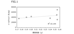
- FIG. 1 is a diagram showing the relationship between the coefficient of friction of a resin coating and the yield torque.
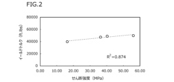
- FIG. 2 is a diagram showing the relationship between the shear strength of a resin coating and the yield torque.
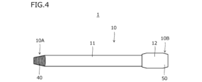
- FIG. 4 is a configuration diagram showing an example of the oil well metal pipe according to this embodiment.
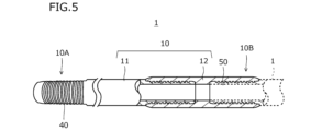
- 5 is a partial cross-sectional view showing a cross section (longitudinal cross section) parallel to the tube axis direction of the coupling of the oil well metal pipe shown in FIG.
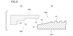
- FIG. 6 is a cross-sectional view of the portion of the metal oil well pipe shown in FIG.
- FIG. 7 is a cross-sectional view parallel to the pipe axis direction of the oil well metal pipe of the box vicinity portion of the oil well metal pipe shown in FIG.
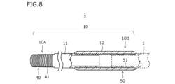
- FIG. 8 shows an example of a metal oil well pipe in which the pin includes a male threaded portion and does not include a pin seal surface and a pin shoulder surface, and the box includes a female threaded portion and does not include a box seal surface and a box shoulder surface. It is a diagram.
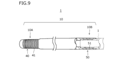
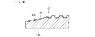
- FIG. 9 is a configuration diagram of an integral type oil well metal pipe according to the present embodiment. 10 is an enlarged view of the pin contact surface shown in FIG. 6; FIG. 11 is an enlarged view of the box contact surface shown in FIG. 7; FIG.
- the inventors studied a metal oil well pipe that can be fastened with a higher torque than before, and that can be applied to an oil well pipe connection used for horizontal drilling. As a result, the following findings were obtained.
- the oil country tubular goods connected body is formed by screwing together the threaded joints of the oil country tubular goods.
- the torque increases according to the number of revolutions. Especially in the final stage of screw tightening, the torque rises sharply.
- the screw tightening torque is too high, the oil well metal pipe may yield.
- the torque at which the oil well metal pipe yields when screwed is also referred to as "yield torque".
- yield torque the higher the yield torque, the higher the torque that can be applied to the oil well metal pipe. In other words, the yield torque can be used as an indicator of whether or not the oil well metal pipe can be fastened with a high torque.
- FIG. 1 is a diagram showing the relationship between the coefficient of friction of a resin coating and the yield torque.
- the horizontal axis of FIG. 1 indicates the coefficient of friction ( ⁇ ) of the resin coating.
- the vertical axis in FIG. 1 indicates the yield torque (ft.lbs) when the oil well metal pipe having the resin film formed thereon is screwed.
- the correlation coefficient R2 between the coefficient of friction of the resin coating and the yield torque was 0.144. From these results, almost no positive correlation is observed between the coefficient of friction of the resin coating and the yield torque. That is, contrary to the expectations of the inventors, it has become clear that the correlation between the friction coefficient and the yield torque is weak. In short, as a result of investigations by the present inventors, it has become clear that simply increasing the friction coefficient of the resin coating does not effectively increase the yield torque.
- the inventors conducted further studies on metal pipes for oil wells that can be fastened with high torque.
- the inventors paid attention to the behavior of the resin coating in the final stage of screw tightening.
- the resin films come into contact with each other with high surface pressure and slide.
- the inventors thought that the resin coating might receive a slipping force (shear force) from the pin contact surface and the box contact surface. If the resin coating receives a shear force exceeding the shear strength of the resin coating, the resin coating will be destroyed. As a result, the oil well metal pipe may be prone to yield.
- FIG. 2 is a diagram showing the relationship between the shear strength of a resin coating and the yield torque.
- the horizontal axis of FIG. 2 indicates the shear strength (MPa) of the resin coating.
- the vertical axis in FIG. 2 indicates the yield torque (ft.lbs) when screwing the oil well metal pipe on which the resin coating is formed.
- the correlation coefficient R2 between the shear strength of the resin coating and the yield torque was 0.874. From this result, a strong positive correlation is recognized between the shear strength of the resin coating and the yield torque. In other words, as a result of detailed studies by the present inventors, it has become clear that the yield torque of the oil well metal pipe can be effectively increased by increasing the shear strength of the resin coating.
- the present inventors investigated a method for increasing the shear strength of the resin coating. As a result, it became clear that the shear strength of the resin coating could be increased by including solid powder of hydrated magnesium silicate and/or TiO 2 . Therefore, the present inventors investigated in detail the shear strength of a resin coating containing hydrous magnesium silicate powder and/or TiO 2 .
- the present inventors focused on the components in the resin film and investigated means for increasing the shear strength.
- resin 50.0 to 99.5% by mass
- wax 0 to 10.0% by mass
- fluorine additive 0 to 30.0% by mass
- graphite 0 to 10.0% by mass
- rust prevention Pigment 0 to 30.0% by mass
- coloring pigment 0 to 10.0% by mass
- coupling agent 0 to 10.0% by mass
- hydrated magnesium silicate powder 1.5 to 50 0% by mass
- TiO 2 0.5 to 30.0% by mass.
- FIG. 3 is a diagram showing the relationship between F1 in the resin coating and the shear strength of the resin coating.
- FIG. 3 is a partial excerpt of the results of the examples described later.
- the horizontal axis of FIG. 3 indicates F1.
- the vertical axis in FIG. 3 indicates the shear strength (MPa) of the resin coating. Referring to FIG. 3, when F1 is 5.00 or less, the shear strength of the resin coating is 36.00 MPa or more. The reason for this is not clarified in detail, but the inventors presume as follows.
- the hydrated magnesium silicate is particles having high shear strength in the crystals.
- TiO 2 is a hard particle in the resin coating with the above composition. If the resin coating contains a large amount of these components, when the resin coating is subjected to a shearing force, the particles themselves will resist the shearing force, thereby suppressing the shear failure of the resin coating. That is, it is considered that the shear strength of the resin coating increases as the contents of the hydrous magnesium silicate powder and TiO 2 increase. On the other hand, wax, fluorine-based additives, and graphite lower the hardness of the resin coating.
- the shear strength of the resin film decreases as the content of wax, fluorine-based additive, and graphite increases. Therefore, the present inventors believe that the shear strength can be increased by reducing the ratio of the total content of wax, fluorine-based additive, and graphite to the total content of hydrous magnesium silicate powder and TiO2 . is guessing.
- An oil well metal pipe a tube body including a first end and a second end;
- the pipe body is a pin formed at the first end; a box formed at the second end;
- the pin is including a pin contact surface including an externally threaded portion;
- the box is including a box contact surface including an internal thread;
- the oil well metal pipe further comprises: a resin coating on or above at least one of the pin contact surface and the box contact surface;
- the resin coating is Resin: 50.0 to 99.5% by mass, Wax: 0 to 10.0% by mass, Fluorine-based additive: 0 to 30.0% by mass, Graphite: 0 to 10.0% by mass, Antirust pigment: 0 to 30.0% by mass, Coloring pigment: 0 to 10.0% by mass, and Coupling agent: 0 to 10.0% by mass, Hydrous magnesium silicate powder: 1.5 to 50.0% by mass, and TiO 2 : containing one or two selected from the group consisting of 0.5 to 30.0% by mass, satisfying formula (1), Metal
- W is the content of wax in mass%
- F is the content of fluorine-based additive in mass%
- G is the content of graphite in mass%
- M is the content of the hydrated magnesium silicate powder in mass %
- T is the content of TiO 2 in mass %.
- the metal pipe for oil well according to [1],
- the resin is One or two selected from the group consisting of epoxy resins and urethane resins, Metal pipe for oil wells.
- the pin contact surface further includes a pin seal surface and a pin shoulder surface
- the box contact surface further includes a box seal surface and a box shoulder surface
- Metal pipe for oil wells
- Oil well metal pipes have a well-known configuration.
- Oil well metal pipes include T&C type oil well metal pipes and integral type oil well metal pipes. Each type of oil well metal pipe will be described in detail below.
- FIG. 4 is a configuration diagram showing an example of the oil well metal pipe 1 according to this embodiment.
- FIG. 4 is a configuration diagram of a so-called T&C type (Threaded and Coupled) oil well metal pipe 1 .
- oil well metal pipe 1 includes pipe body 10 .
- the pipe body 10 extends in the pipe axial direction.
- a cross section of the pipe body 10 perpendicular to the pipe axis direction is circular.
- the tube body 10 includes a first end 10A and a second end 10B.
- the first end 10A is the end opposite to the second end 10B.
- a coupling 12 is attached to one end of the pin tube body 11 . More specifically, the coupling 12 is screwed to one end of the pin tube 11 .
- FIG. 5 is a partial cross-sectional view showing a cross section (longitudinal cross section) parallel to the tube axis direction of the coupling 12 of the oil well metal pipe 1 shown in FIG. 4 and 5, tube body 10 includes pin 40 and box 50. As shown in FIG. The pin 40 is formed on the first end portion 10A of the tube body 10 . When fastening, the pin 40 is inserted into the box 50 of another oil well metal pipe 1 (not shown) and fastened to the box 50 of the other oil well metal pipe 1 by screws.
- the box 50 is formed at the second end 10B of the pipe body 10. At the time of fastening, the pin 40 of the other oil well metal pipe 1 is inserted into the box 50 and is fastened with the pin 40 of the other oil well metal pipe 1 by screws.
- FIG. 6 is a cross-sectional view parallel to the pipe axis direction of the oil well metal pipe 1 of the portion near the pin 40 of the oil well metal pipe 1 shown in FIG.
- a broken line portion in FIG. 6 shows the configuration of the box 50 of another oil well metal pipe 1 when fastening with another oil well metal pipe 1 .
- the pin 40 has a pin contact surface 400 on the outer peripheral surface of the first end 10A of the pipe body 10. As shown in FIG. The pin contact surface 400 is screwed into the box 50 of the other oil well metal pipe 1 and comes into contact with the box contact surface 500 (described later) of the box 50 when fastening with the other oil well metal pipe 1 .
- the pin contact surface 400 includes at least a male threaded portion 41 formed on the outer peripheral surface of the first end portion 10A.
- Pin contact surface 400 may further include pin seal surface 42 and pin shoulder surface 43 .
- the pin shoulder surface 43 is arranged on the distal end surface of the first end portion 10A, and the pin seal surface 42 is located closer to the distal end side of the first end portion 10A than the male thread portion 41 on the outer peripheral surface of the first end portion 10A. are placed. That is, the pin seal surface 42 is arranged between the male threaded portion 41 and the pin shoulder surface 43 .
- the pin seal surface 42 is provided in a tapered shape. Specifically, the outer diameter of the pin seal surface 42 gradually decreases from the male threaded portion 41 toward the pin shoulder surface 43 in the longitudinal direction (pipe axis direction) of the first end portion 10A.
- the pin seal surface 42 contacts the box seal surface 52 (described later) of the box 50 of the other oil well metal pipe 1 . More specifically, when the pin 40 is inserted into the box 50 of the other metal pipe 1 for oil wells, the pin seal surface 42 comes into contact with the box seal surface 52 . By further screwing the pin 40 into the box 50 of the other oil well metal pipe 1 , the pin seal surface 42 is brought into close contact with the box seal surface 52 . As a result, during fastening, the pin seal surface 42 is in close contact with the box seal surface 52 to form a seal based on metal-to-metal contact. Therefore, the airtightness can be improved in the metal pipes 1 for oil wells that are fastened to each other.
- the pin shoulder surface 43 is arranged on the tip surface of the first end portion 10A. That is, in the pin 40 shown in FIG. 6, the male threaded portion 41, the pin seal surface 42, and the pin shoulder surface 43 are arranged in order from the center of the pipe body 10 toward the first end portion 10A.
- the pin shoulder surface 43 faces and comes into contact with the box shoulder surface 53 (described later) of the box 50 of the other oil well metal pipe 1 . More specifically, when the pin 40 is inserted into the box 50 of the other oil well metal pipe 1 , the pin shoulder surface 43 comes into contact with the box shoulder surface 53 during fastening. Thereby, high torque can be obtained at the time of fastening. Also, the positional relationship between the pin 40 and the box 50 in the fastened state can be stabilized.
- pin contact surface 400 of the pin 40 includes at least the male threaded portion 41 . That is, pin contact surface 400 may include external threads 41 and not include pin seal surface 42 and pin shoulder surface 43 . Pin contact surface 400 includes external threads 41 and pin shoulder surface 43 and may not include pin seal surface 42 . Pin contact surface 400 may include external threads 41 and pin seal surface 42 and may not include pin shoulder surface 43 .
- FIG. 7 is a cross-sectional view parallel to the pipe axis direction of the oil well metal pipe 1 of the box 50 vicinity portion of the oil well metal pipe 1 shown in FIG.
- a broken line portion in FIG. 7 shows the configuration of the pin 40 of another oil well metal pipe 1 when fastening with another oil well metal pipe 1 .
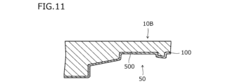
- box 50 has a box contact surface 500 on the inner peripheral surface of second end 10B of tube body 10 .
- the pin 40 of the other oil well metal pipe 1 is screwed into the box contact surface 500 and contacts the pin contact surface 400 of the pin 40 when the box contact surface 500 is fastened with the other oil well metal pipe 1 .
- the box contact surface 500 includes at least a female threaded portion 51 formed on the inner peripheral surface of the second end portion 10B. At the time of fastening, the female threaded portion 51 meshes with the male threaded portion 41 of the pin 40 of the other oil well metal pipe 1 .
- the box contact surface 500 may further include a box sealing surface 52 and a box shoulder surface 53.
- the box seal surface 52 is arranged closer to the pipe main body 10 than the female threaded portion 51 on the inner peripheral surface of the second end portion 10B. That is, the box seal surface 52 is arranged between the female threaded portion 51 and the box shoulder surface 53 .
- the box seal surface 52 is tapered. Specifically, in the box seal surface 52, the inner diameter gradually decreases from the female threaded portion 51 toward the box shoulder surface 53 in the longitudinal direction (pipe axis direction) of the second end portion 10B.
- the box seal surface 52 When fastening with another oil well metal pipe 1 , the box seal surface 52 contacts the pin seal surface 42 of the pin 40 of the other oil well metal pipe 1 . More specifically, when the pin 40 of the other oil well metal pipe 1 is screwed into the box 50 at the time of fastening, the box seal surface 52 comes into contact with the pin seal surface 42, and further screwing causes the box seal surface 52 is in close contact with the pin seal surface 42 . As a result, during fastening, the box seal surface 52 is in close contact with the pin seal surface 42 to form a seal based on metal-to-metal contact. Therefore, the airtightness can be improved in the metal pipes 1 for oil wells that are fastened to each other.
- the box shoulder surface 53 is arranged closer to the pipe main body 10 than the box seal surface 52 is. That is, in the box 50, the box shoulder surface 53, the box seal surface 52, and the internal thread portion 51 are arranged in this order from the center of the pipe body 10 toward the tip of the second end portion 10B.
- the box shoulder surface 53 faces and contacts the pin shoulder surface 43 of the pin 40 of the other oil well metal pipe 1 . More specifically, when fastening, the box shoulder surface 53 contacts the pin shoulder surface 43 by inserting the pin 40 of the other oil well metal pipe 1 into the box 50 . Thereby, high torque can be obtained at the time of fastening. Also, the positional relationship between the pin 40 and the box 50 in the fastened state can be stabilized.
- the box contact surface 500 includes at least the female threaded portion 51 .
- the female threaded portion 51 of the box contact surface 500 of the box 50 corresponds to the male threaded portion 41 of the pin contact surface 400 of the pin 40 and contacts the male threaded portion 41 .
- Box seal surface 52 corresponds to pin seal surface 42 and contacts pin seal surface 42 .
- Box shoulder surface 53 corresponds to pin shoulder surface 43 and contacts pin shoulder surface 43 .
- the box contact surface 500 includes the female threaded portion 51 and does not include the box seal surface 52 and the box shoulder surface 53. If pin contact surface 400 includes external threads 41 and pin shoulder surface 43 but does not include pin seal surface 42 , box contact surface 500 includes internal threads 51 and box shoulder surface 53 but does not include box seal surface 52 . If pin contact surface 400 includes male threads 41 and pin seal surface 42 but does not include pin shoulder surface 43 , box contact surface 500 includes female threads 51 and box seal surface 52 but does not include box shoulder surface 53 .
- the pin contact surface 400 may include multiple external threads 41 , multiple pin seal surfaces 42 , or multiple pin shoulder surfaces 43 .
- the pin shoulder surface 43, the pin seal surface 42, the male threaded portion 41, the pin seal surface 42, the pin shoulder surface 43, the pin seal surface from the tip of the first end portion 10A toward the center of the pipe body 10. 42 and the male threaded portion 41 may be arranged in this order.
- the box contact surface 500 of the box 50 from the tip of the second end portion 10B toward the center of the pipe body 10, the female threaded portion 51, the box sealing surface 52, the box shoulder surface 53, the box sealing surface 52, the female threaded portion. 51 , box sealing surface 52 , and box shoulder surface 53 .
- the pin 40 includes a male threaded portion 41, a pin seal surface 42 and a pin shoulder surface 43
- the box 50 includes a female threaded portion 51, a box seal surface 52 and a box shoulder surface 53.
- pin 40 may include external threads 41 and not include pin seal surface 42 and pin shoulder surface 43
- box 50 includes internal threads 51 and does not include box seal surface 52 and box shoulder surface 53
- FIG. 8 shows that pin 40 includes male threaded portion 41 and does not include pin seal surface 42 and pin shoulder surface 43
- box 50 includes female threaded portion 51 and does not include box seal surface 52 and box shoulder surface 53. It is a figure which shows an example of the metal pipe 1 for oil wells.
- the oil well metal pipe 1 shown in FIGS. 4, 5 and 8 is a so-called T&C type oil well metal pipe 1 in which a pipe body 10 includes a pin pipe body 11 and a coupling 12 .
- the oil well metal pipe 1 of the present embodiment may be of the integral type instead of the T&C type.
- FIG. 9 is a configuration diagram of an integral type oil well metal pipe 1 according to this embodiment.
- an integral type oil well metal pipe 1 includes a pipe body 10 .
- the tube body 10 includes a first end 10A and a second end 10B.
- the first end 10A is arranged opposite to the second end 10B.
- the pipe body 10 includes the pin pipe body 11 and the coupling 12 . That is, in the T&C type oil well metal pipe 1, the pipe body 10 is configured by fastening two separate members (the pin pipe body 11 and the coupling 12).
- the pipe main body 10 is integrally formed.
- the pin 40 is formed on the first end portion 10A of the pipe body 10. At the time of fastening, the pin 40 is inserted and screwed into the box 50 of the other integral type oil well metal pipe 1 and fastened to the box 50 of the other integral type oil well metal pipe 1 .
- a box 50 is formed at the second end 10B of the tube body 10 . At the time of fastening, the pin 40 of the other integral type oil well metal pipe 1 is inserted and screwed into the box 50 to be fastened with the pin 40 of the other integral type oil well metal pipe 1 .
- the configuration of the pin 40 of the integral type oil well metal tube 1 is the same as the configuration of the pin 40 of the T&C type oil well metal tube 1 shown in FIG.
- the configuration of the box 50 of the integral type oil well metal pipe 1 is the same as the configuration of the box 50 of the T&C type oil well metal pipe 1 shown in FIG. 6 and 7, in the pin 40, the pin shoulder surface 43, the pin seal surface 42, and the male screw portion 41 are arranged in this order from the tip of the first end portion 10A toward the center of the pipe body 10.
- the female screw portion 51, the box seal surface 52, and the box shoulder surface 53 are arranged in this order.
- the pin contact surface 400 of the pin 40 of the integral type oil well metal tube 1 should include at least the male threaded portion 41. good.
- the box contact surface 500 of the box 50 of the integral type oil well metal pipe 1 should include at least the female screw portion 51. good.
- the oil well metal pipe 1 of this embodiment may be of the T&C type or the integral type.
- the oil well metal pipe 1 of this embodiment has a resin coating 100 on or above at least one of the pin contact surface 400 and the box contact surface 500 .
- FIG. 10 is an enlarged view of pin contact surface 400 shown in FIG.
- FIG. 11 is an enlarged view of the box contact surface 500 shown in FIG.
- the oil well metal pipe 1 according to this embodiment may have a resin coating 100 on both the pin contact surface 400 and the box contact surface 500 .
- the oil well metal pipe 1 according to this embodiment may be provided with the resin coating 100 only on either the pin contact surface 400 or the box contact surface 500 . For example, as shown in FIG.
- the oil well metal pipe 1 has the resin coating 100 on the pin contact surface 400 and/or the box contact surface 500 .
- the resin coating 100 contains the following components.
- the resin contained in the resin coating 100 according to this embodiment is not particularly limited. However, it is considered that the resin coating 100 receives a shear force when the oil well metal pipe 1 is fastened. Therefore, in order to stably increase the yield torque of the oil well metal pipe 1 on which the resin coating 100 is formed, it is preferable to use a resin having an appropriate hardness.
- the resin in the resin film 100 according to the present embodiment includes epoxy resin, phenol resin, acrylic resin, urethane resin, polyester resin, polyamideimide resin, polyamide resin, polyimide resin, and polyether ether ketone resin.
- the resin in this embodiment is one or more selected from the group consisting of epoxy resins, urethane resins, polyimide resins, and phenol resins, and more preferably selected from the group consisting of epoxy resins and urethane resins. more preferably one of epoxy resin and urethane resin.
- the resin coating 100 may contain multiple types of resins. When a plurality of types of resins are contained, the resin content means the total content of the plurality of types of resins.
- Resin is the base material of the resin coating 100 .
- the base material means the component contained in the resin film 100 in the largest amount. If the content of the resin is too low, it becomes difficult to disperse the composition such as the hydrous magnesium silicate powder described later in the resin. As a result, the shear strength of the resin coating is lowered. On the other hand, if the content of the resin is too high, the hydrous magnesium silicate powder and/or other components including TiO 2 cannot be sufficiently contained. As a result, the shear strength of the resin coating 100 rather decreases. Therefore, the resin content is 50.0 to 99.5% by mass. A preferable lower limit of the resin content is 55.0% by mass, more preferably 60.0% by mass, and still more preferably 65.0% by mass. A preferable upper limit of the resin content is 97.0% by mass, more preferably 95.0% by mass, and still more preferably 90.0% by mass.
- the resin coating 100 contains one or two selected from the group consisting of hydrous magnesium silicate powder and TiO 2 . Specifically, it contains one or two selected from the group consisting of hydrated magnesium silicate powder: 1.5 to 50.0% by mass and TiO 2 : 0.5 to 30.0% by mass. All of these components increase the shear strength of the resin coating 100 .
- Hydrous magnesium silicate powder 1.5 to 50.0% by mass
- the hydrated magnesium silicate powder is a component that is optionally contained, and may not be contained. That is, the content of the hydrated magnesium silicate powder may be 0% by mass.
- the hydrated magnesium silicate powder increases the shear strength of the resin coating 100 .
- a hydrous magnesium silicate powder is a solid powder having a layered structure.
- the hydrous magnesium silicate powder also has high bonding strength between layers and high shear strength. In other words, the hydrous magnesium silicate powder is particles having high shear strength in the crystals.
- the hydrous magnesium silicate powder resists the shearing and suppresses the shear failure of the resin coating 100 .
- the hydrated magnesium silicate powder is considered to increase the shear strength of the resin coating 100 .
- the content of the hydrated magnesium silicate powder is 1.5 to 50.0% by mass.
- the preferable lower limit of the content of the hydrated magnesium silicate powder is 2.0% by mass, more preferably 4.0% by mass, still more preferably 7.0% by mass, still more preferably 10.0% by mass. be.
- a preferable upper limit of the content of the hydrated magnesium silicate powder is 45.0% by mass, more preferably 43.0% by mass, and still more preferably 40.0% by mass.
- TiO 2 0.5 to 30.0% by mass
- TiO 2 is an optional component and may not be included. That is, the content of TiO 2 may be 0% by mass.
- TiO 2 enhances the shear strength of the resin coating 100 .
- TiO2 is hard powder particles. Therefore, when the resin coating 100 receives a shearing force, the TiO 2 resists the shearing and suppresses the shear fracture of the resin coating 100 . Thus, TiO 2 is considered to increase the shear strength of the resin coating 100 .
- the content of TiO 2 is too high, it may promote abrasive wear and reduce the seizure resistance of the oil well metal pipe 1 .
- the content of TiO 2 is 0.5-30.0% by mass.
- the preferred lower limit of the content of TiO2 is 0.7% by mass, more preferably 1.0% by mass, more preferably 2.0% by mass, still more preferably 2.5% by mass, More preferably, it is 5.0% by mass.
- a preferable upper limit of the content of TiO 2 is 25.0% by mass, more preferably 20.0% by mass, further preferably 15.0% by mass.
- Wax 0 to 10.0% by mass
- the type of wax contained in the resin coating 100 according to this embodiment is not particularly limited.
- Waxes are, for example, one or more selected from the group consisting of animal waxes, vegetable waxes, mineral waxes and synthetic waxes.
- waxes include beeswax, spermaceti (or animal wax), Japan wax, carnauba wax, candelilla wax, rice wax (or vegetable wax), paraffin wax, microcrystalline wax, petrolatum, montan wax, One or more selected from the group consisting of ozokerite, ceresin (all minerals), oxidized wax, polyethylene wax, polypropylene wax, Fischer-Tropsch wax, amide wax, hardened castor oil (castor wax) (all synthetic waxes) is. More preferably, the wax is one or two selected from the group consisting of polyethylene wax and polypropylene wax.
- the resin coating 100 may contain multiple types of wax. When multiple types of wax are contained, the wax content means the total content of the multiple types of wax.
- wax is a component that is optionally contained, and may not be contained. That is, the wax content may be 0% by mass.
- the wax enhances the lubricity of the resin coating 100 .
- the wax content is 0 to 10.0% by mass.
- the lower limit of the wax content is preferably 0.1% by mass, more preferably 0.5% by mass, still more preferably 1.0% by mass, still more preferably 2.0% by mass.
- the upper limit of the wax content is preferably 9.0% by mass, more preferably 8.0% by mass, still more preferably 7.5% by mass.
- Fluorine-based additive 0 to 30.0% by mass
- fluorine-containing additives are also collectively referred to as fluorine-based additives.
- the fluorine-based additive is, for example, one or two selected from the group consisting of perfluoropolyether (PFPE) and polytetrafluoroethylene (PTFE).
- PFPE perfluoropolyether
- PTFE polytetrafluoroethylene
- the resin coating 100 may contain a plurality of types of fluorine-based additives. When a plurality of types of fluorine-based additives are contained, the content of fluorine-based additives means the total content of the plurality of types of fluorine-based additives.
- the fluorine-based additive is a component that is optionally contained, and may not be contained. That is, the content of the fluorine-based additive may be 0% by mass.
- the fluorine-based additive enhances the lubricity of the resin coating 100 . As long as the fluorine-based additive is contained even in a small amount, the above effects can be obtained to some extent.
- the content of the fluorine-based additive is too high, the hardness of the resin coating 100 is lowered. As a result, the shear strength of the resin coating 100 may decrease. Therefore, the content of the fluorine-based additive is 0 to 30.0% by mass.
- a preferred lower limit for the content of the fluorine-based additive is 1.0% by mass, more preferably 3.0% by mass, still more preferably 4.5% by mass, and still more preferably 7.5% by mass. be.
- a preferable upper limit of the content of the fluorine-based additive is 25.0% by mass, more preferably 20.0% by mass, still more preferably 15.0% by mass, still more preferably 12.5% by mass. be.
- graphite 0 to 10.0% by mass
- graphite is an optional component and may not be included. That is, the content of graphite may be 0% by mass.
- graphite enhances the lubricity of the resin coating 100 . The above effects can be obtained to some extent if even a small amount of graphite is contained.
- the content of graphite is 0 to 10.0% by mass.
- a preferable lower limit of the graphite content is 1.0% by mass, more preferably 2.0% by mass, and still more preferably 3.0% by mass.
- the upper limit of the graphite content is preferably 9.0% by mass, more preferably 8.0% by mass, still more preferably 7.0% by mass.
- Antirust pigment 0 to 30.0% by mass
- the rust preventive pigment is not particularly limited as long as it is a known pigment that enhances the rust preventiveness of the resin coating 100 .
- the antirust pigment is, for example, one or more selected from the group consisting of zinc phosphate, aluminum tripolyphosphate, aluminum phosphite, carboxylic acid metal soap, and sulfonate.
- the resin coating 100 may contain multiple types of antirust pigments. When a plurality of types of rust preventive pigments are contained, the content of the rust preventive pigments means the total content of the plurality of types of rust preventive pigments.
- the antirust pigment is an optional component and may not be included. That is, the content of the rust preventive pigment may be 0% by mass.
- the rust preventive pigment enhances the rust preventiveness of the resin coating 100 . If even a small amount of rust preventive pigment is contained, the above effect can be obtained to some extent. On the other hand, if the content of the rust preventive pigment is too high, the resin coating 100 will be poorly formed. Therefore, the content of the rust preventive pigment is 0 to 30.0% by mass.
- a preferable lower limit of the content of the rust preventive pigment is 1.0% by mass, more preferably 2.0% by mass, still more preferably 3.0% by mass, and still more preferably 4.0% by mass. .
- a preferable upper limit of the content of the rust preventive pigment is 25.0% by mass, more preferably 20.0% by mass, and still more preferably 10.0% by mass.
- the coloring pigment is not particularly limited as long as it is a known pigment capable of coloring the resin coating 100 .
- the coloring pigment is, for example, one or more selected from the group consisting of phthalocyanine copper, zinc oxide, yellow iron oxide, iron oxide, and chromium hydroxide.
- the resin coating 100 may contain multiple types of color pigments. When multiple types of color pigments are contained, the content of the color pigments means the total content of the multiple types of color pigments.
- the color pigment is a component that is arbitrarily contained and may not be contained. That is, the content of the coloring pigment may be 0% by mass.
- the coloring pigment colors the resin coating 100 .
- damage to the resin coating 100 becomes easier to visually recognize.
- the content of the coloring pigment is 0 to 10.0% by mass.
- a preferable lower limit of the content of the color pigment is 0.1% by mass, more preferably 0.2% by mass, and still more preferably 0.5% by mass.
- the upper limit of the content of the color pigment is preferably 8.0% by mass, more preferably 5.0% by mass, and still more preferably 3.0% by mass.
- the coupling agent is not particularly limited, but is, for example, one or two selected from the group consisting of silane coupling agents and titanium coupling agents.
- the resin coating 100 may contain multiple types of coupling agents. When multiple types of coupling agents are contained, the content of the coupling agents means the total content of the multiple types of coupling agents.
- the coupling agent is an optional component and may not be included. That is, the content of the coupling agent may be 0% by mass.
- the coupling agent enhances adhesion of the resin coating 100 . Therefore, when the oil well metal pipe 1 is repeatedly screwed and unscrewed, peeling of the resin coating 100 is suppressed. As long as the coupling agent is contained even in a small amount, the above effect can be obtained to some extent.
- the content of the coupling agent exceeds 10.0% by mass, the formation of the resin film 100 becomes defective. Therefore, the content of the coupling agent is 0 to 10.0% by mass.
- a preferable lower limit of the content of the coupling agent is 0.1% by mass, more preferably 0.2% by mass, and still more preferably 0.5% by mass.
- a preferable upper limit of the content of the coupling agent is 8.0% by mass, more preferably 6.0% by mass, further preferably 4.0% by mass.
- Other components 0 to 10.0% by mass
- other components are optional components and may not be included. That is, the content of other components may be 0% by mass.
- Other components are, for example, one or two selected from the group consisting of preservatives and antioxidants. When other components are contained, the total content of the other components is 10.0% by mass or less. That is, the total content of other components is 0 to 10.0% by mass.
- the resin film 100 contains resin: 50.0 to 99.5% by mass, wax: 0 to 10.0% by mass, fluorine-based additive: 0 to 30.0% by mass, graphite: 0 to 10.0% by mass, Antirust pigment: 0 to 30.0% by mass, coloring pigment: 0 to 10.0% by mass, coupling agent: 0 to 10.0% by mass, other components: 0 to 10.0% by mass, and water content
- the resin coating 100 may be one or two selected from the group consisting of magnesium silicate powder: 1.5 to 50.0% by mass and TiO 2 : 0.5 to 30.0% by mass. .
- the resin coating 100 satisfies the formula (1) on the premise that it contains the above components. (W+F+G)/(M+T) ⁇ 5.00 (1)
- W is the content of wax in mass%
- F is the content of fluorine-based additive in mass%
- G is the content of graphite in mass%
- M is the content of the hydrated magnesium silicate powder in mass %
- T is the content of TiO 2 in mass %.
- the shear strength of the resin coating 100 increases as the contents of the hydrous magnesium silicate powder and TiO 2 increase.
- the shear strength of the resin coating 100 decreases as the content of wax, fluorine-based additive, and graphite increases. Therefore, the shear strength of the resin coating 100 can be increased by reducing the ratio of the total content of wax, fluorine-based additive, and graphite to the total content of hydrous magnesium silicate powder and TiO 2 .
- the shear strength of the resin coating 100 having the components described above, it has been proved by examples described later that by setting F1 to 5.00 or less, the shear strength of the resin coating 100 can be increased to 36.00 MPa or more.
- F1 is set to 5.00 or less on the premise that the resin film 100 has the above components.
- a preferable upper limit of F1 is 4.90, more preferably 4.80, and still more preferably 4.70.
- the lower limit of F1 is not particularly limited, and may be 0.00.
- the shear strength of the resin film 100 is increased by containing the above components and satisfying the formula (1). As a result, the oil well metal pipe 1 provided with the resin coating 100 has an increased yield torque.
- shear strength of the resin coating 100 is not particularly limited, it is preferably as high as possible. If the shear strength of the resin coating 100 is 36.00 MPa or more, the yield torque of the oil well metal pipe 1 provided with the resin coating 100 can be significantly increased. Therefore, the shear strength of the resin coating 100 is preferably 36.00 MPa or more. A more preferable lower limit of the shear strength of the resin coating 100 is 36.50 MPa, more preferably 36.70 MPa, still more preferably 37.00 MPa. Although the upper limit of the shear strength of the resin coating 100 is not particularly limited, it is, for example, 70.00 MPa.
- the shear strength of the resin coating 100 can be measured by the following method.
- the shear strength of the test piece on which the resin coating 100 is formed is determined using a surface/interface property analyzer (manufactured by Daipla-Wintes Co., Ltd., trade name: SAICAS).
- SAICAS surface/interface property analyzer
- the resin coating 100 is a cold-rolled steel sheet (the chemical composition is C ⁇ 0.15%, Mn ⁇ 0.60%, P ⁇ 0.100%, S ⁇ 0.050%, and the balance: Fe and impurities).
- the target film thickness is set to 20 ⁇ m.
- the surface of the resin coating 100 is cut at an angle of 10° at a constant speed (horizontal speed 2 ⁇ m/sec, vertical speed 0.2 ⁇ m/sec), and the resin coating 100 is cooled. It is made to separate from the rolled steel plate. All tests are performed at room temperature. At this time, the shear strength (MPa) of the resin coating 100 can be obtained from the horizontal force, vertical force, and vertical displacement applied to the cutting edge.
- MPa shear strength
- the thickness of the resin coating 100 is not particularly limited.
- the thickness of the resin coating 100 is, for example, 1-100 ⁇ m. In this case, the yield torque of the oil well metal pipe 1 can be increased more stably.
- the lower limit of the thickness of the resin coating 100 is preferably 2 ⁇ m, more preferably 5 ⁇ m, and still more preferably 10 ⁇ m.
- the upper limit of the thickness of the resin coating 100 is preferably 50 ⁇ m, more preferably 40 ⁇ m, and even more preferably 30 ⁇ m.
- the thickness of the resin coating 100 can be measured by the following method.
- a probe of an electromagnetic induction type film thickness measuring device is brought into contact with the pin contact surface 400 or the box contact surface 500 on which the resin film 100 is formed.
- the probe has an electromagnet, and when a magnetic body is brought close to it, electromagnetic induction occurs, and the voltage changes depending on the distance between the probe and the magnetic body.
- the thickness of the resin coating 100 is obtained from the change in the amount of voltage.
- the measurement points are 12 points (0°, 30°, 60°, 90°, 120°, 150°, 180°, 210°, 240°, 270°, 300°, 12 points of 330°).
- the arithmetic average value of the measurement results at 12 points is taken as the thickness of the resin coating 100 .
- the chemical composition of the pipe main body 10 of the oil well metal pipe 1 according to this embodiment is not particularly limited. That is, in the present embodiment, the steel type of the pipe main body 10 of the oil well metal pipe 1 is not particularly limited.
- the pipe body 10 may be made of, for example, carbon steel, stainless steel, alloys, or the like. That is, the oil well metal pipe 1 may be a steel pipe made of an Fe-based alloy, or may be an alloy pipe represented by a Ni-based alloy pipe.
- the steel pipe is, for example, a low-alloy steel pipe, a martensitic stainless steel pipe, a duplex stainless steel pipe, or the like.
- Ni-based alloys and high alloy steels such as duplex stainless steels containing alloying elements such as Cr, Ni and Mo have high corrosion resistance. Therefore, if these high-alloy steels are used for the pipe body 10, excellent corrosion resistance can be obtained in corrosive environments containing hydrogen sulfide, carbon dioxide, and the like.
- the method for manufacturing the oil well metal pipe 1 includes a preparation process, a coating process, and a curing process.
- a curing step is performed after the coating step.
- an oil well metal pipe 1 is prepared that includes a pipe body 10 that includes a pin 40 that includes a pin contact surface 400 that includes a male threaded portion 41 and a box 50 that includes a box contact surface 500 that includes a female threaded portion 51 .
- the oil well metal pipe 1 according to this embodiment has a well-known configuration. That is, in the preparation step, the oil well metal pipe 1 having a well-known configuration may be prepared.
- the composition is applied to at least one of the pin contact surface 400 and the box contact surface 500 of the prepared oil well metal pipe 1 .
- the composition is a composition for forming the resin coating 100 described above.
- the composition contains resin: 50.0 to 99.5% by mass, wax: 0 to 10.0% by mass, fluorine-based additive: 0 to 30.0% by mass, graphite: 0 to 10.0% by mass, and Rust pigment: 0 to 30.0% by mass, coloring pigment: 0 to 10.0% by mass, and coupling agent: 0 to 10.0% by mass, hydrated magnesium silicate powder: 1.5 to 50.0% by mass.
- composition further contains a solvent.
- the composition excluding the solvent of the composition for forming the resin coating 100 is the same as the composition of the resin coating 100 described above.
- the composition can be produced, for example, by dissolving or dispersing the resin, hydrated magnesium silicate powder and/or TiO 2 and, if necessary, other components in a solvent and mixing them.
- the solvent is, for example, one or more selected from the group consisting of water, alcohol, and organic solvents.
- the solvent may contain trace amounts of surfactants.
- the ratio of the solvent is not particularly limited. The proportion of the solvent may be adjusted according to the coating method so that the composition has an appropriate viscosity.
- the ratio of the solvent is, for example, 40 to 60% by mass when the total of all components other than the solvent is 100% by mass.
- the method of applying the composition onto the pin contact surface 400 and/or the box contact surface 500 is not particularly limited, and any known method may be used.
- the composition in solution is applied onto the pin contact surface 400 and/or the box contact surface 500 by spraying.
- the composition is adjusted in viscosity so that it can be applied by spraying under an environment of normal temperature and normal pressure.
- the method of applying the composition onto the pin contact surface 400 and/or the box contact surface 500 may be brushing, dipping, or the like instead of spraying.
- the applied composition is cured to form the resin coating 100 .
- the composition is thermally cured to form a solid resin coating 100 .
- a heating method is not particularly limited, and a known method may be used.
- the heating method is, for example, a method in which the oil well metal pipe 1 coated with the composition is placed in a known heating furnace and heated.
- the heating temperature is, for example, 200-250° C., and the heating time is, for example, 5-30 minutes.
- the oil well metal pipe 1 according to the present embodiment is manufactured.
- the method for manufacturing the oil well metal pipe 1 according to the present embodiment may include other steps.
- the method for manufacturing the oil well metal pipe 1 according to the present embodiment may further include a surface treatment step before the coating step.
- a surface treatment step for example, one or more selected from the group consisting of pickling treatment, blasting treatment and alkali degreasing treatment is carried out.
- the pin contact surfaces 400 and/or the box contact surfaces 500 are immersed in a strong acid solution such as sulfuric acid, hydrochloric acid, nitric acid, hydrofluoric acid, or a mixed acid of these to remove the pin contact surfaces 400. and/or increase the surface roughness of the box contact surface 500;
- a strong acid solution such as sulfuric acid, hydrochloric acid, nitric acid, hydrofluoric acid, or a mixed acid of these to remove the pin contact surfaces 400. and/or increase the surface roughness of the box contact surface 500;
- blasting for example, sandblasting is performed by mixing a blasting material (abrasive) and compressed air and projecting it onto the pin contact surface 400 and/or the box contact surface 500 . In this case, the surface roughness of the pin contact surface 400 and/or the box contact surface 500 is increased.
- the pin contact surface 400 and the box contact surface 500 may be subjected to the same treatment or different treatments. Also, the priming process may be performed only on the pin contact surfaces 400 or only on the box contact surfaces 500 .
- the oil well metal pipe 1 according to the present embodiment is manufactured.
- the manufacturing method described above is an example of the manufacturing method of the oil well metal pipe 1 according to the present embodiment, and is not limited to this manufacturing method.
- the oil well metal pipe 1 according to this embodiment may be manufactured by other methods.
- the effects of the metal pipe for oil wells of this embodiment will be described more specifically by way of examples.
- the conditions in the following examples are examples of conditions adopted for confirming the feasibility and effect of the metal pipe for oil wells of this embodiment. Therefore, the oil well metal pipe of the present embodiment is not limited to this one condition example.
- a composition for forming a resin film was prepared and the shear strength of the resin film was evaluated. Specifically, it is as follows.
- Table 1 shows each component (% by mass) of the composition of each test number and F1 obtained from each component and formula (1).
- the composition contained a solvent other than the composition described in Table 1.
- a mixed solution of water, alcohol and surfactant was used as the solvent.
- the prepared composition was applied to a cold-rolled steel sheet (chemical composition: C ⁇ 0.15%, Mn ⁇ 0.60%, P ⁇ 0.100%, S ⁇ 0.050%, the balance: Fe and impurities). painted the object.
- the target film thickness was set to 20 ⁇ m.
- the cold-rolled steel sheet coated with the composition was heated in a heating furnace at 200-250° C. for 5-30 minutes to form a resin coating.
- the shear strength was measured for the cold-rolled steel sheets of each test number on which the resin coating was formed. Shear strength was measured by the method described above. Table 1 shows the obtained shear strength (MPa) of each test number.
- the resin coatings of test numbers 23 and 24 contained neither hydrous magnesium silicate powder nor TiO2 . As a result, these resin coatings had a shear strength of less than 36.00 MPa and did not have high shear strength.
- test numbers 25 to 28 did not satisfy formula (1), although the content of each component was appropriate. As a result, these resin coatings had a shear strength of less than 36.00 MPa and did not have high shear strength.
- test numbers 29 and 30 had too low a resin content. As a result, these resin coatings had a shear strength of less than 36.00 MPa and did not have high shear strength.
Landscapes
- Engineering & Computer Science (AREA)
- Chemical & Material Sciences (AREA)
- General Engineering & Computer Science (AREA)
- Wood Science & Technology (AREA)
- Life Sciences & Earth Sciences (AREA)
- Materials Engineering (AREA)
- Organic Chemistry (AREA)
- Mechanical Engineering (AREA)
- Inorganic Chemistry (AREA)
- Non-Disconnectible Joints And Screw-Threaded Joints (AREA)
- Paints Or Removers (AREA)
- Laminated Bodies (AREA)
- Lubricants (AREA)
- Other Surface Treatments For Metallic Materials (AREA)
Abstract
Description
第1端部と第2端部とを含む管本体を備え、
前記管本体は、
前記第1端部に形成されているピンと、
前記第2端部に形成されているボックスとを含み、
前記ピンは、
雄ねじ部を含むピン接触表面を含み、
前記ボックスは、
雌ねじ部を含むボックス接触表面を含み、
前記油井用金属管はさらに、
前記ピン接触表面及び前記ボックス接触表面の少なくとも一方の上又は上方に、樹脂被膜を備え、
前記樹脂被膜は、
樹脂:50.0~99.5質量%、
ワックス:0~10.0質量%、
フッ素系添加剤:0~30.0質量%、
黒鉛:0~10.0質量%、
防錆顔料:0~30.0質量%、
着色顔料:0~10.0質量%、及び、
カップリング剤:0~10.0質量%を含有し、
含水珪酸マグネシウム粉末:1.5~50.0質量%、及び、
TiO2:0.5~30.0質量%からなる群から選択される1種又は2種を含有し、
式(1)を満たす、
油井用金属管。
(W+F+G)/(M+T)≦5.00 (1)
ここで、式(1)中のWにはワックスの含有量が質量%で、Fにはフッ素系添加剤の含有量が質量%で、Gには黒鉛の含有量が質量%で、Mには含水珪酸マグネシウム粉末の含有量が質量%で、TにはTiO2の含有量が質量%で、それぞれ代入される。
(W+F+G)/(M+T)≦5.00 (1)
ここで、式(1)中のWにはワックスの含有量が質量%で、Fにはフッ素系添加剤の含有量が質量%で、Gには黒鉛の含有量が質量%で、Mには含水珪酸マグネシウム粉末の含有量が質量%で、TにはTiO2の含有量が質量%で、それぞれ代入される。
油井用金属管であって、
第1端部と第2端部とを含む管本体を備え、
前記管本体は、
前記第1端部に形成されているピンと、
前記第2端部に形成されているボックスとを含み、
前記ピンは、
雄ねじ部を含むピン接触表面を含み、
前記ボックスは、
雌ねじ部を含むボックス接触表面を含み、
前記油井用金属管はさらに、
前記ピン接触表面及び前記ボックス接触表面の少なくとも一方の上又は上方に、樹脂被膜を備え、
前記樹脂被膜は、
樹脂:50.0~99.5質量%、
ワックス:0~10.0質量%、
フッ素系添加剤:0~30.0質量%、
黒鉛:0~10.0質量%、
防錆顔料:0~30.0質量%、
着色顔料:0~10.0質量%、及び、
カップリング剤:0~10.0質量%を含有し、
含水珪酸マグネシウム粉末:1.5~50.0質量%、及び、
TiO2:0.5~30.0質量%からなる群から選択される1種又は2種を含有し、
式(1)を満たす、
油井用金属管。
(W+F+G)/(M+T)≦5.00 (1)
ここで、式(1)中のWにはワックスの含有量が質量%で、Fにはフッ素系添加剤の含有量が質量%で、Gには黒鉛の含有量が質量%で、Mには含水珪酸マグネシウム粉末の含有量が質量%で、TにはTiO2の含有量が質量%で、それぞれ代入される。
[1]に記載の油井用金属管であって、
前記樹脂は、
エポキシ樹脂及びウレタン樹脂からなる群から選択される1種又は2種である、
油井用金属管。
[1]又は[2]に記載の油井用金属管であって、
前記ピン接触表面はさらに、ピンシール面及びピンショルダ面を含み、
前記ボックス接触表面はさらに、ボックスシール面及びボックスショルダ面を含む、
油井用金属管。
初めに、本実施形態の油井用金属管の構成について説明する。油井用金属管は、周知の構成を有する。油井用金属管は、T&C型の油井用金属管と、インテグラル型の油井用金属管とがある。以下、各型の油井用金属管について詳述する。
図4は、本実施形態による油井用金属管1の一例を示す構成図である。図4は、いわゆるT&C型(Threaded and Coupled)の油井用金属管1の構成図である。図4を参照して、油井用金属管1は、管本体10を備える。
図6は、図5に示す油井用金属管1のうちのピン40近傍部分の、油井用金属管1の管軸方向に平行な断面図である。図6中の破線部分は、他の油井用金属管1と締結する場合の、他の油井用金属管1のボックス50の構成を示す。図6を参照して、ピン40は、管本体10の第1端部10Aの外周面に、ピン接触表面400を備える。ピン接触表面400は、他の油井用金属管1との締結時において、他の油井用金属管1のボックス50にねじ込まれ、ボックス50のボックス接触表面500(後述)と接触する。
図7は、図5に示す油井用金属管1のうちのボックス50近傍部分の、油井用金属管1の管軸方向に平行な断面図である。図7中の破線部分は、他の油井用金属管1と締結する場合の、他の油井用金属管1のピン40の構成を示す。図7を参照して、ボックス50は、管本体10の第2端部10Bの内周面に、ボックス接触表面500を備える。ボックス接触表面500は、他の油井用金属管1との締結時において、他の油井用金属管1のピン40がねじ込まれ、ピン40のピン接触表面400と接触する。
図4、図5及び図8に示す油井用金属管1は、管本体10が、ピン管体11とカップリング12とを含む、いわゆる、T&C型の油井用金属管1である。しかしながら、本実施形態の油井用金属管1は、T&C型ではなく、インテグラル型であってもよい。
本実施形態の油井用金属管1は、ピン接触表面400及びボックス接触表面500の少なくとも一方の上又は上方に、樹脂被膜100を備える。図10は、図6に示すピン接触表面400の拡大図である。図11は、図7に示すボックス接触表面500の拡大図である。図10及び図11に示すように、本実施形態による油井用金属管1は、ピン接触表面400及びボックス接触表面500の両方の上に、樹脂被膜100を備えてもよい。しかしながら、本実施形態による油井用金属管1は、ピン接触表面400又はボックス接触表面500の一方の上のみに、樹脂被膜100を備えてもよい。たとえば、図10に示すように、ピン接触表面400上に樹脂被膜100を備える場合、ボックス接触表面500上には、樹脂被膜100を備えなくてもよい。また、図11に示すように、ボックス接触表面500上に樹脂被膜100を備える場合、ピン接触表面400上には、樹脂被膜100を備えなくてもよい。言い換えると、本実施形態による油井用金属管1は、ピン接触表面400上及び/又はボックス接触表面500上に、樹脂被膜100を備える。
樹脂被膜100は、以下の成分を含有する。
本実施形態による樹脂被膜100中に含有する樹脂は、特に限定されない。しかしながら、油井用金属管1の締結時に、樹脂被膜100はせん断力を受けると考えられる。そのため、樹脂被膜100が形成された油井用金属管1のイールドトルクを安定して高めるには、適度な硬さを有する樹脂を用いることが好ましい。以上の観点から、本実施形態による樹脂被膜100中において、樹脂は、エポキシ樹脂、フェノール樹脂、アクリル樹脂、ウレタン樹脂、ポリエステル樹脂、ポリアミドイミド樹脂、ポリアミド樹脂、ポリイミド樹脂、及び、ポリエーテルエーテルケトン樹脂からなる群から選択される1種以上である。好ましくは、本実施形態における樹脂はエポキシ樹脂、ウレタン樹脂、ポリイミド樹脂、及び、フェノール樹脂からなる群から選択される1種以上であり、さらに好ましくは、エポキシ樹脂及びウレタン樹脂からなる群から選択される1種又は2種であり、さらに好ましくはエポキシ樹脂及びウレタン樹脂のうちいずれか1種である。樹脂被膜100は、複数の種類の樹脂を含有してもよい。複数の種類の樹脂を含有する場合、樹脂の含有量とは、複数の種類の樹脂の合計含有量を意味する。
本実施形態において、含水珪酸マグネシウム粉末は任意に含有される成分であり、含有されなくてもよい。すなわち、含水珪酸マグネシウム粉末の含有量は、0質量%であってもよい。含有される場合、含水珪酸マグネシウム粉末は、樹脂被膜100のせん断強度を高める。含水珪酸マグネシウム粉末は、層状の組織を有する固体粉末である。含水珪酸マグネシウム粉末はさらに、この層間の結合力が高く、せん断強度が高い。つまり、含水珪酸マグネシウム粉末は結晶内のせん断強度が高い粒子である。そのため、樹脂被膜100がせん断力を受けた場合に、含水珪酸マグネシウム粉末がせん断に抵抗して、樹脂被膜100のせん断破壊を抑制する。このようにして、含水珪酸マグネシウム粉末は、樹脂被膜100のせん断強度を高めると考えられる。一方、含水珪酸マグネシウム粉末の含有量が高すぎれば、樹脂の含有量が相対的に低下して、かえって樹脂被膜100のせん断強度が低下する。したがって、含有される場合、含水珪酸マグネシウム粉末の含有量は1.5~50.0質量%である。含水珪酸マグネシウム粉末の含有量の好ましい下限は2.0質量%であり、さらに好ましくは4.0質量%であり、さらに好ましくは7.0質量%であり、さらに好ましくは10.0質量%である。含水珪酸マグネシウム粉末の含有量の好ましい上限は45.0質量%であり、さらに好ましくは43.0質量%であり、さらに好ましくは40.0質量%である。
本実施形態において、TiO2は任意に含有される成分であり、含有されなくてもよい。すなわち、TiO2の含有量は0質量%であってもよい。含有される場合、TiO2は、樹脂被膜100のせん断強度を高める。TiO2は硬い粉末粒子である。そのため、樹脂被膜100がせん断力を受けた場合に、TiO2がせん断に抵抗して、樹脂被膜100のせん断破壊を抑制する。このようにして、TiO2は、樹脂被膜100のせん断強度を高めると考えられる。一方、TiO2の含有量が高すぎれば、アブレシブ摩耗を促進し、油井用金属管1の耐焼付き性を低下させる場合がある。したがって、含有される場合、TiO2の含有量は0.5~30.0質量%である。TiO2の含有量の好ましい下限は0.7質量%であり、さらに好ましくは1.0質量%であり、さらに好ましくは2.0質量%であり、さらに好ましくは2.5質量%であり、さらに好ましくは5.0質量%である。TiO2の含有量の好ましい上限は25.0質量%であり、さらに好ましくは20.0質量%であり、さらに好ましくは15.0質量%である。
本実施形態による樹脂被膜100中に含有するワックスの種類は、特に限定されない。ワックスはたとえば、動物性ワックス、植物性ワックス、鉱物性ワックス及び合成ワックスからなる群から選択される1種以上である。さらに具体的には、ワックスは、蜜蝋、鯨蝋(以上、動物性)、木蝋、カルナバワックス、キャンデリラワックス、ライスワックス(以上、植物性)、パラフィンワックス、マイクロクリスタリンワックス、ペトロラタム、モンタンワックス、オゾケライト、セレシン(以上、鉱物性)、酸化ワックス、ポリエチレンワックス、ポリプロピレンワックス、フィッシャー・トロプッシュワックス、アミドワックス、硬化ひまし油(カスターワックス)(以上、合成ワックス)からなる群から選択される1種以上である。さらに好ましくは、ワックスは、ポリエチレンワックス及びポリプロピレンワックスからなる群から選択される1種又は2種である。樹脂被膜100は、複数の種類のワックスを含有してもよい。複数の種類のワックスを含有する場合、ワックスの含有量とは、複数の種類のワックスの合計含有量を意味する。
本明細書において、フッ素を含有する添加剤を総称して、フッ素系添加剤ともいう。フッ素系添加剤は、たとえば、パーフルオロポリエーテル(PFPE)及びポリテトラフルオロエチレン(PTFE)からなる群から選択される1種又は2種である。樹脂被膜100は、複数の種類のフッ素系添加剤を含有してもよい。複数の種類のフッ素系添加剤を含有する場合、フッ素系添加剤の含有量とは、複数の種類のフッ素系添加剤の合計含有量を意味する。
本実施形態において、黒鉛は任意に含有される成分であり、含有されなくてもよい。すなわち、黒鉛の含有量は0質量%であってもよい。含有される場合、黒鉛は、樹脂被膜100の潤滑性を高める。黒鉛が少しでも含有されれば、上記効果はある程度得られる。一方、黒鉛の含有量が高すぎれば、樹脂被膜100の硬さが低下する。その結果、樹脂被膜100のせん断強度が低下する場合がある。したがって、黒鉛の含有量は0~10.0質量%である。黒鉛の含有量の好ましい下限は1.0質量%であり、さらに好ましくは2.0質量%であり、さらに好ましくは3.0質量%である。黒鉛の含有量の好ましい上限は9.0質量%であり、さらに好ましくは8.0質量%であり、さらに好ましくは7.0質量%である。
本実施形態において、防錆顔料は、樹脂被膜100の防錆性を高める周知の顔料であれば特に限定されない。防錆顔料はたとえば、リン酸亜鉛、トリポリリン酸アルミニウム、亜燐酸アルミニウム、カルボン酸金属石鹸、及び、スルホン酸塩からなる群から選択される1種以上である。樹脂被膜100は、複数の種類の防錆顔料を含有してもよい。複数の種類の防錆顔料を含有する場合、防錆顔料の含有量とは、複数の種類の防錆顔料の合計含有量を意味する。
本実施形態において、着色顔料は、樹脂被膜100を着色できる周知の顔料であれば特に限定されない。着色顔料はたとえば、フタロシアニン銅、酸化亜鉛、黄酸化鉄、酸化鉄、及び、水酸化クロムからなる群から選択される1種以上である。樹脂被膜100は、複数の種類の着色顔料を含有してもよい。複数の種類の着色顔料を含有する場合、着色顔料の含有量とは、複数の種類の着色顔料の合計含有量を意味する。
本実施形態において、カップリング剤は特に限定されないが、たとえば、シランカップリング剤及びチタンカップリング剤からなる群から選択される1種又は2種である。樹脂被膜100は、複数の種類のカップリング剤を含有してもよい。複数の種類のカップリング剤を含有する場合、カップリング剤の含有量とは、複数の種類のカップリング剤の合計含有量を意味する。
本実施形態において、その他の成分は任意に含有される成分であり、含有されなくてもよい。すなわち、その他の成分の含有量は、0質量%であってもよい。その他の成分とはたとえば、防腐剤、及び、酸化防止剤からなる群から選択される1種又は2種である。その他の成分が含有される場合、その他の成分の含有量は合計で10.0質量%以下である。つまり、その他の成分の含有量は合計で0~10.0質量%である。
樹脂被膜100は、上述の成分を含有することを前提として、式(1)を満たす。
(W+F+G)/(M+T)≦5.00 (1)
ここで、式(1)中のWにはワックスの含有量が質量%で、Fにはフッ素系添加剤の含有量が質量%で、Gには黒鉛の含有量が質量%で、Mには含水珪酸マグネシウム粉末の含有量が質量%で、TにはTiO2の含有量が質量%で、それぞれ代入される。
樹脂被膜100のせん断強度は特に限定されないが、高い方が好ましい。樹脂被膜100のせん断強度が36.00MPa以上であれば、樹脂被膜100を備える油井用金属管1のイールドトルクを顕著に高めることができる。したがって、樹脂被膜100のせん断強度は36.00MPa以上であるのが好ましい。樹脂被膜100のせん断強度のさらに好ましい下限は36.50MPaであり、さらに好ましくは36.70MPaであり、さらに好ましくは37.00MPaである。樹脂被膜100のせん断強度の上限は特に限定されないが、たとえば70.00MPaである。
樹脂被膜100のせん断強度は次の方法で測定できる。樹脂被膜100を形成した試験片に対して、表面・界面物性解析装置(ダイプラ・ウィンテス株式会社製、商標名:SAICAS)を用いて、せん断強度を求める。具体的には、樹脂被膜100を冷延鋼板(化学組成は、C≦0.15%、Mn≦0.60%、P≦0.100%、S≦0.050%、及び、残部:Fe及び不純物)に形成する。狙い膜厚は20μmとする。鋭利な切削刃を用いて、樹脂被膜100の表面に対して一定速度(水平速度2μm/秒、垂直速度0.2μm/秒)のもと、10°で斜めに切削し、樹脂被膜100を冷延鋼板から剥離させる。なお、試験は全て室温で実施する。このとき、切削刃にかかる水平力と垂直力と垂直変位とから、樹脂被膜100のせん断強度(MPa)を求めることができる。
本実施形態において、樹脂被膜100の厚さは特に限定されない。樹脂被膜100の厚さはたとえば、1~100μmである。この場合、油井用金属管1のイールドトルクをより安定して高めることができる。樹脂被膜100の厚さの下限は好ましくは2μmであり、さらに好ましくは5μmであり、さらに好ましくは10μmである。樹脂被膜100の厚さの上限は好ましくは50μmであり、さらに好ましくは40μmであり、さらに好ましくは30μmである。
樹脂被膜100の厚さは、次の方法で測定できる。樹脂被膜100を形成したピン接触表面400又はボックス接触表面500上に、電磁誘導式の膜厚測定器のプローブを接触させる。プローブは電磁石を有しており、磁性体を近づけると電磁誘導が起こり、プローブと磁性体との距離に依存してその電圧が変化する。電圧量の変化から樹脂被膜100の厚さを求める。測定箇所は、油井用金属管1の管周方向の12箇所(0°、30°、60°、90°、120°、150°、180°、210°、240°、270°、300°、330°の12箇所)である。12箇所の測定結果の算術平均値を、樹脂被膜100の厚さとする。
本実施形態による油井用金属管1の管本体10の化学組成は、特に限定されない。すなわち、本実施形態において、油井用金属管1の管本体10の鋼種は特に限定されない。管本体10は、たとえば、炭素鋼、ステンレス鋼及び合金等によって形成されていてもよい。つまり、油井用金属管1とは、Fe基合金からなる鋼管であってもよく、Ni基合金管に代表される合金管であってもよい。ここで、鋼管はたとえば、低合金鋼管、マルテンサイト系ステンレス鋼管、二相ステンレス鋼管等である。一方、合金鋼の中でも、Ni基合金及びCr、Ni及びMo等の合金元素を含んだ二相ステンレス鋼等の高合金鋼は、耐食性が高い。そのため、これらの高合金鋼を管本体10として使用すれば、硫化水素や二酸化炭素等を含有する腐食環境において、優れた耐食性が得られる。
以下、本実施形態による油井用金属管1の製造方法を説明する。
準備工程では、雄ねじ部41を含むピン接触表面400を含むピン40と、雌ねじ部51を含むボックス接触表面500を含むボックス50とを含む管本体10を備える油井用金属管1を準備する。上述のとおり、本実施形態による油井用金属管1は、周知の構成を有する。すなわち、準備工程では、周知の構成を有する油井用金属管1を準備すればよい。
塗布工程では、準備された油井用金属管1のうち、ピン接触表面400及びボックス接触表面500の少なくとも一方の上に、組成物を塗布する。組成物は、上述の樹脂被膜100を形成するための組成物である。組成物は、樹脂:50.0~99.5質量%、ワックス:0~10.0質量%、フッ素系添加剤:0~30.0質量%、黒鉛:0~10.0質量%、防錆顔料:0~30.0質量%、着色顔料:0~10.0質量%、及び、カップリング剤:0~10.0質量%を含有し、含水珪酸マグネシウム粉末:1.5~50.0質量%、及び、TiO2:0.5~30.0質量%からなる群から選択される1種又は2種を含有し、かつ、式(1)を満たす。組成物はさらに、溶媒を含有する。樹脂被膜100を形成するための組成物の、溶媒を除いた組成は、上述の樹脂被膜100の組成と同じである。
硬化工程では、塗布された組成物を硬化して樹脂被膜100を形成する。ピン接触表面400及びボックス接触表面500の少なくとも一方の上に塗布された組成物を加熱することにより、組成物が熱硬化して固体の樹脂被膜100が形成される。加熱方法は特に限定されず、周知の方法でよい。加熱方法はたとえば、周知の加熱炉に、組成物を塗布した油井用金属管1を入れて加熱する方法である。加熱温度はたとえば、200~250℃、加熱時間はたとえば、5~30分である。
本実施形態による油井用金属管1の製造方法はさらに、塗布工程の前に、下地処理工程を備えてもよい。下地処理工程では、たとえば、酸洗処理、ブラスト処理及びアルカリ脱脂処理からなる群から選択される1種以上を実施する。
表1に示す組成を有する組成物を準備した。各試験番号の組成物の各成分(質量%)と、各成分と式(1)とから求めたF1を表1に示す。なお、組成物は、表1に記載された組成以外に溶媒を含有した。溶媒は、水、アルコール及び界面活性剤の混合溶液を使用した。準備した組成物を冷延鋼板(化学組成は、C≦0.15%、Mn≦0.60%、P≦0.100%、S≦0.050%、残部:Fe及び不純物)に、組成物を塗布した。狙いの膜厚は20μmとした。組成物を塗布した冷延鋼板を、200~250℃の加熱炉で5~30分間加熱して、樹脂被膜を形成した。
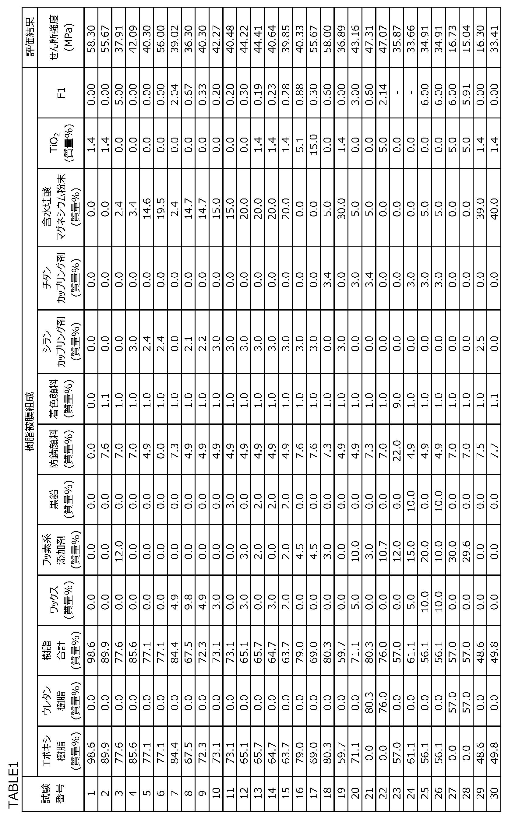
表1を参照して、試験番号1~22の樹脂被膜は、各成分の含有量が適切であり、さらに、式(1)を満たした。その結果、これらの樹脂被膜はせん断強度が36.00MPa以上となり、高いせん断強度を有していた。
10 管本体
10A 第1端部
10B 第2端部
11 ピン管体
12 カップリング
40 ピン
41 雄ねじ部
42 ピンシール面
43 ピンショルダ面
50 ボックス
51 雌ねじ部
52 ボックスシール面
53 ボックスショルダ面
100 樹脂被膜
400 ピン接触表面
500 ボックス接触表面
Claims (3)
- 油井用金属管であって、
第1端部と第2端部とを含む管本体を備え、
前記管本体は、
前記第1端部に形成されているピンと、
前記第2端部に形成されているボックスとを含み、
前記ピンは、
雄ねじ部を含むピン接触表面を含み、
前記ボックスは、
雌ねじ部を含むボックス接触表面を含み、
前記油井用金属管はさらに、
前記ピン接触表面及び前記ボックス接触表面の少なくとも一方の上又は上方に、樹脂被膜を備え、
前記樹脂被膜は、
樹脂:50.0~99.5質量%、
ワックス:0~10.0質量%、
フッ素系添加剤:0~30.0質量%、
黒鉛:0~10.0質量%、
防錆顔料:0~30.0質量%、
着色顔料:0~10.0質量%、及び、
カップリング剤:0~10.0質量%を含有し、
含水珪酸マグネシウム粉末:1.5~50.0質量%、及び、
TiO2:0.5~30.0質量%からなる群から選択される1種又は2種を含有し、
式(1)を満たす、
油井用金属管。
(W+F+G)/(M+T)≦5.00 (1)
ここで、式(1)中のWにはワックスの含有量が質量%で、Fにはフッ素系添加剤の含有量が質量%で、Gには黒鉛の含有量が質量%で、Mには含水珪酸マグネシウム粉末の含有量が質量%で、TにはTiO2の含有量が質量%で、それぞれ代入される。 - 請求項1に記載の油井用金属管であって、
前記樹脂は、
エポキシ樹脂及びウレタン樹脂からなる群から選択される1種又は2種である、
油井用金属管。 - 請求項1又は請求項2に記載の油井用金属管であって、
前記ピン接触表面はさらに、ピンシール面及びピンショルダ面を含み、
前記ボックス接触表面はさらに、ボックスシール面及びボックスショルダ面を含む、
油井用金属管。
Priority Applications (7)
| Application Number | Priority Date | Filing Date | Title |
|---|---|---|---|
| US18/700,561 US12510191B2 (en) | 2021-10-15 | 2022-10-13 | Oil-well metal pipe |
| CN202280068949.8A CN118103628A (zh) | 2021-10-15 | 2022-10-13 | 油井用金属管 |
| CA3232798A CA3232798A1 (en) | 2021-10-15 | 2022-10-13 | Oil-well metal pipe |
| MX2024004591A MX2024004591A (es) | 2021-10-15 | 2022-10-13 | Tubo de metal para pozos de petroleo. |
| EP22881080.0A EP4417849A4 (en) | 2021-10-15 | 2022-10-13 | METAL PIPE FOR OIL WELLS |
| AU2022364506A AU2022364506B2 (en) | 2021-10-15 | 2022-10-13 | Oil-Well Metal Pipe |
| JP2023554610A JP7781172B2 (ja) | 2021-10-15 | 2022-10-13 | 油井用金属管 |
Applications Claiming Priority (2)
| Application Number | Priority Date | Filing Date | Title |
|---|---|---|---|
| JP2021-169258 | 2021-10-15 | ||
| JP2021169258 | 2021-10-15 |
Publications (1)
| Publication Number | Publication Date |
|---|---|
| WO2023063385A1 true WO2023063385A1 (ja) | 2023-04-20 |
Family
ID=85988701
Family Applications (1)
| Application Number | Title | Priority Date | Filing Date |
|---|---|---|---|
| PCT/JP2022/038194 Ceased WO2023063385A1 (ja) | 2021-10-15 | 2022-10-13 | 油井用金属管 |
Country Status (9)
| Country | Link |
|---|---|
| US (1) | US12510191B2 (ja) |
| EP (1) | EP4417849A4 (ja) |
| JP (1) | JP7781172B2 (ja) |
| CN (1) | CN118103628A (ja) |
| AR (1) | AR127340A1 (ja) |
| AU (1) | AU2022364506B2 (ja) |
| CA (1) | CA3232798A1 (ja) |
| MX (1) | MX2024004591A (ja) |
| WO (1) | WO2023063385A1 (ja) |
Citations (6)
| Publication number | Priority date | Publication date | Assignee | Title |
|---|---|---|---|---|
| JP2003021278A (ja) | 2001-04-11 | 2003-01-24 | Sumitomo Metal Ind Ltd | 鋼管用ねじ継手 |
| WO2006104251A1 (en) | 2005-03-29 | 2006-10-05 | Sumitomo Metal Industries, Ltd. | Threaded joint for steel pipes |
| JP2010511135A (ja) * | 2006-12-01 | 2010-04-08 | テナリス・コネクシヨンズ・アクチエンゲゼルシヤフト | ねじ込み連結部用のナノ複合コーティング |
| CN103270146A (zh) * | 2010-07-20 | 2013-08-28 | 特纳瑞斯连接有限责任公司 | 具有改进的密封性、润滑性和耐腐蚀性的接头 |
| WO2015141159A1 (ja) * | 2014-03-20 | 2015-09-24 | 新日鐵住金株式会社 | 固体潤滑被膜用組成物、その組成物から形成された固体潤滑被膜を備えた管用ねじ継手、及び、その管用ねじ継手の製造方法 |
| WO2018216416A1 (ja) * | 2017-05-22 | 2018-11-29 | 新日鐵住金株式会社 | 管用ねじ継手及び管用ねじ継手の製造方法 |
Family Cites Families (13)
| Publication number | Priority date | Publication date | Assignee | Title |
|---|---|---|---|---|
| JPH03268940A (ja) | 1990-03-19 | 1991-11-29 | Sumitomo Metal Ind Ltd | 耐熱・耐硫化水素割れ性に優れた絶縁被覆金属管および継手 |
| CN1056510A (zh) | 1990-05-11 | 1991-11-27 | 西安航空电气公司 | 油田井下注水钢管防腐蚀涂料 |
| US20060127622A1 (en) | 2004-11-24 | 2006-06-15 | Mohan Pidatala K | System of pipes for use in oil wells |
| FR2914926B1 (fr) * | 2007-04-11 | 2013-11-01 | Vallourec Mannesmann Oil & Gas | Composition de lubrification a coefficient de frottement adaptable, pour un element filete d'un composant de joint filete tubulaire. |
| EA017703B1 (ru) * | 2007-12-04 | 2013-02-28 | Сумитомо Метал Индастриз, Лтд. | Резьбовое соединение для труб |
| US8535762B2 (en) * | 2009-10-09 | 2013-09-17 | Tenaris Connections Limited | Tubular joint having wedge threads with surface coating |
| UA105334C2 (uk) | 2010-11-05 | 2014-04-25 | Ниппон Стил Энд Сумитомо Метал Корпорэйшн | Нарізне з'єднання труб, що має поліпшені характеристики при високому крутному моменті |
| CN102329553B (zh) * | 2011-08-04 | 2013-08-14 | 上海海隆赛能新材料有限公司 | 油井管防偏磨粉末涂料 |
| UA109617C2 (uk) * | 2012-01-19 | 2015-09-10 | Нарізне з'єднання для труб | |
| AR100804A1 (es) * | 2014-06-23 | 2016-11-02 | Nippon Steel & Sumitomo Metal Corp | Conexión roscada para tuberías de la industria del petróleo y composición para recubrimiento fotocurable |
| EP3258151B1 (en) | 2015-02-13 | 2020-05-27 | Sanoh Industrial Co., Ltd. | Coated metal pipe for vehicle piping and method for producing same |
| BR112018004565B1 (pt) * | 2015-09-18 | 2022-07-26 | Vallourec Oil And Gas France | Composição, junta roscada para tubos incluindo revestimento lubrificante sólido formado a partir da composição e método para produzir a junta roscada para tubos |
| CN110651147B (zh) * | 2017-05-22 | 2021-06-01 | 日本制铁株式会社 | 管用螺纹接头及管用螺纹接头的制造方法 |
-
2022
- 2022-10-12 AR ARP220102773A patent/AR127340A1/es unknown
- 2022-10-13 MX MX2024004591A patent/MX2024004591A/es unknown
- 2022-10-13 CA CA3232798A patent/CA3232798A1/en active Pending
- 2022-10-13 AU AU2022364506A patent/AU2022364506B2/en active Active
- 2022-10-13 US US18/700,561 patent/US12510191B2/en active Active
- 2022-10-13 JP JP2023554610A patent/JP7781172B2/ja active Active
- 2022-10-13 WO PCT/JP2022/038194 patent/WO2023063385A1/ja not_active Ceased
- 2022-10-13 EP EP22881080.0A patent/EP4417849A4/en active Pending
- 2022-10-13 CN CN202280068949.8A patent/CN118103628A/zh active Pending
Patent Citations (6)
| Publication number | Priority date | Publication date | Assignee | Title |
|---|---|---|---|---|
| JP2003021278A (ja) | 2001-04-11 | 2003-01-24 | Sumitomo Metal Ind Ltd | 鋼管用ねじ継手 |
| WO2006104251A1 (en) | 2005-03-29 | 2006-10-05 | Sumitomo Metal Industries, Ltd. | Threaded joint for steel pipes |
| JP2010511135A (ja) * | 2006-12-01 | 2010-04-08 | テナリス・コネクシヨンズ・アクチエンゲゼルシヤフト | ねじ込み連結部用のナノ複合コーティング |
| CN103270146A (zh) * | 2010-07-20 | 2013-08-28 | 特纳瑞斯连接有限责任公司 | 具有改进的密封性、润滑性和耐腐蚀性的接头 |
| WO2015141159A1 (ja) * | 2014-03-20 | 2015-09-24 | 新日鐵住金株式会社 | 固体潤滑被膜用組成物、その組成物から形成された固体潤滑被膜を備えた管用ねじ継手、及び、その管用ねじ継手の製造方法 |
| WO2018216416A1 (ja) * | 2017-05-22 | 2018-11-29 | 新日鐵住金株式会社 | 管用ねじ継手及び管用ねじ継手の製造方法 |
Non-Patent Citations (1)
| Title |
|---|
| See also references of EP4417849A4 |
Also Published As
| Publication number | Publication date |
|---|---|
| AU2022364506B2 (en) | 2026-04-09 |
| CA3232798A1 (en) | 2023-04-20 |
| EP4417849A1 (en) | 2024-08-21 |
| CN118103628A (zh) | 2024-05-28 |
| EP4417849A4 (en) | 2024-12-11 |
| AR127340A1 (es) | 2024-01-10 |
| AU2022364506A1 (en) | 2024-05-02 |
| US20250314335A1 (en) | 2025-10-09 |
| JP7781172B2 (ja) | 2025-12-05 |
| US12510191B2 (en) | 2025-12-30 |
| JPWO2023063385A1 (ja) | 2023-04-20 |
| MX2024004591A (es) | 2024-04-30 |
Similar Documents
| Publication | Publication Date | Title |
|---|---|---|
| CN110651148B (zh) | 管用螺纹接头及管用螺纹接头的制造方法 | |
| JP6815498B2 (ja) | 管用ねじ継手及び管用ねじ継手の製造方法 | |
| JP7550865B2 (ja) | 油井用金属管 | |
| WO2015141159A1 (ja) | 固体潤滑被膜用組成物、その組成物から形成された固体潤滑被膜を備えた管用ねじ継手、及び、その管用ねじ継手の製造方法 | |
| JP7583817B2 (ja) | 油井用金属管及び油井用金属管の製造方法 | |
| WO2020149310A1 (ja) | 管用ねじ継手及び管用ねじ継手の製造方法 | |
| JP2023164546A (ja) | 組成物、及び、その組成物からなる潤滑被膜層を備える管用ねじ継手 | |
| JP7781172B2 (ja) | 油井用金属管 | |
| JP7817404B2 (ja) | 油井用金属管 | |
| JP7781171B2 (ja) | 油井用金属管 | |
| EA052198B1 (ru) | Металлическая труба для нефтяной скважины | |
| EA052222B1 (ru) | Металлическая труба для нефтяной скважины | |
| WO2025177640A1 (ja) | 油井用金属管及びその油井用金属管の潤滑被膜層を形成するための組成物 | |
| WO2024180941A1 (ja) | 油井用金属管及びその油井用金属管の潤滑被膜層を形成するための組成物 | |
| JP2024106003A (ja) | 油井用金属管及び油井用金属管の潤滑被膜を形成するための組成物 | |
| EA045795B1 (ru) | Металлическая труба для нефтяной скважины и способ ее изготовления |
Legal Events
| Date | Code | Title | Description |
|---|---|---|---|
| 121 | Ep: the epo has been informed by wipo that ep was designated in this application |
Ref document number: 22881080 Country of ref document: EP Kind code of ref document: A1 |
|
| WWE | Wipo information: entry into national phase |
Ref document number: 3232798 Country of ref document: CA |
|
| REG | Reference to national code |
Ref country code: BR Ref legal event code: B01A Ref document number: 112024005910 Country of ref document: BR |
|
| ENP | Entry into the national phase |
Ref document number: 2023554610 Country of ref document: JP Kind code of ref document: A |
|
| WWE | Wipo information: entry into national phase |
Ref document number: 2401002258 Country of ref document: TH |
|
| WWE | Wipo information: entry into national phase |
Ref document number: 202280068949.8 Country of ref document: CN |
|
| WWE | Wipo information: entry into national phase |
Ref document number: 0024000029 Country of ref document: IQ |
|
| WWE | Wipo information: entry into national phase |
Ref document number: MX/A/2024/004591 Country of ref document: MX |
|
| WWE | Wipo information: entry into national phase |
Ref document number: AU2022364506 Country of ref document: AU |
|
| WWE | Wipo information: entry into national phase |
Ref document number: DZP2024000293 Country of ref document: DZ |
|
| ENP | Entry into the national phase |
Ref document number: 2022364506 Country of ref document: AU Date of ref document: 20221013 Kind code of ref document: A |
|
| WWE | Wipo information: entry into national phase |
Ref document number: 202417036817 Country of ref document: IN |
|
| WWE | Wipo information: entry into national phase |
Ref document number: 2022881080 Country of ref document: EP |
|
| NENP | Non-entry into the national phase |
Ref country code: DE |
|
| ENP | Entry into the national phase |
Ref document number: 2022881080 Country of ref document: EP Effective date: 20240515 |
|
| ENP | Entry into the national phase |
Ref document number: 112024005910 Country of ref document: BR Kind code of ref document: A2 Effective date: 20240325 |
|
| WWP | Wipo information: published in national office |
Ref document number: 18700561 Country of ref document: US |