WO2023067865A1 - 航空機用化粧室ユニットのフラッシュスイッチ - Google Patents
航空機用化粧室ユニットのフラッシュスイッチ Download PDFInfo
- Publication number
- WO2023067865A1 WO2023067865A1 PCT/JP2022/028879 JP2022028879W WO2023067865A1 WO 2023067865 A1 WO2023067865 A1 WO 2023067865A1 JP 2022028879 W JP2022028879 W JP 2022028879W WO 2023067865 A1 WO2023067865 A1 WO 2023067865A1
- Authority
- WO
- WIPO (PCT)
- Prior art keywords
- base member
- switch
- flash switch
- wall
- front wall
- Prior art date
- Legal status (The legal status is an assumption and is not a legal conclusion. Google has not performed a legal analysis and makes no representation as to the accuracy of the status listed.)
- Ceased
Links
Images







Classifications
-
- B—PERFORMING OPERATIONS; TRANSPORTING
- B64—AIRCRAFT; AVIATION; COSMONAUTICS
- B64D—EQUIPMENT FOR FITTING IN OR TO AIRCRAFT; FLIGHT SUITS; PARACHUTES; ARRANGEMENT OR MOUNTING OF POWER PLANTS OR PROPULSION TRANSMISSIONS IN AIRCRAFT
- B64D11/00—Passenger or crew accommodation; Flight-deck installations not otherwise provided for
- B64D11/02—Toilet fittings
-
- E—FIXED CONSTRUCTIONS
- E03—WATER SUPPLY; SEWERAGE
- E03D—WATER-CLOSETS OR URINALS WITH FLUSHING DEVICES; FLUSHING VALVES THEREFOR
- E03D5/00—Special constructions of flushing devices, e.g. closed flushing system
- E03D5/10—Special constructions of flushing devices, e.g. closed flushing system operated electrically, e.g. by a photo-cell; also combined with devices for opening or closing shutters in the bowl outlet and/or with devices for raising/or lowering seat and cover and/or for swiveling the bowl
-
- E—FIXED CONSTRUCTIONS
- E03—WATER SUPPLY; SEWERAGE
- E03D—WATER-CLOSETS OR URINALS WITH FLUSHING DEVICES; FLUSHING VALVES THEREFOR
- E03D5/00—Special constructions of flushing devices, e.g. closed flushing system
- E03D5/10—Special constructions of flushing devices, e.g. closed flushing system operated electrically, e.g. by a photo-cell; also combined with devices for opening or closing shutters in the bowl outlet and/or with devices for raising/or lowering seat and cover and/or for swiveling the bowl
- E03D5/105—Special constructions of flushing devices, e.g. closed flushing system operated electrically, e.g. by a photo-cell; also combined with devices for opening or closing shutters in the bowl outlet and/or with devices for raising/or lowering seat and cover and/or for swiveling the bowl touchless, e.g. using sensors
-
- H—ELECTRICITY
- H01—ELECTRIC ELEMENTS
- H01H—ELECTRIC SWITCHES; RELAYS; SELECTORS; EMERGENCY PROTECTIVE DEVICES
- H01H35/00—Switches operated by change of a physical condition
- H01H35/18—Switches operated by change of liquid level or of liquid density, e.g. float switch
-
- E—FIXED CONSTRUCTIONS
- E03—WATER SUPPLY; SEWERAGE
- E03F—SEWERS; CESSPOOLS
- E03F1/00—Methods, systems, or installations for draining-off sewage or storm water
- E03F1/006—Pneumatic sewage disposal systems; accessories specially adapted therefore
Definitions
- the present invention relates to a flush switch for an aircraft lavatory unit.
- Flush valve type toilets are often installed in restrooms of public facilities, trains, aircraft, etc., which are often used continuously by an unspecified number of people.
- a flush valve type toilet the toilet bowl is directly connected to a water supply pipe (water pipe) via a flush valve, and the user operates a flush switch installed on the wall of the restroom to open the flush valve and flush the toilet. Water is flushed into the toilet bowl.
- a flash switch a contact-type flash switch (see Patent Document 1) that is operated by a push button that a user presses with a finger, and a human body sensor that detects a part of the user's human body (fingers) without contact. is known as a non-contact flash switch (see Patent Document 2).
- the former contact type flash switch is generally used, but in recent years, the latter non-contact type flash switch has been desired from the viewpoint of preventing infectious diseases.
- a non-contact flush switch when used, there is a concern that if the non-contact flush switch fails, the flushing function of the toilet will be impaired. Therefore, two types of flash switches, a non-contact flash switch and a contact flash switch, are provided on the wall of the restroom so that the contact flash switch can be operated even if the non-contact flash switch fails. By doing so, it is conceivable that the flushing function of the toilet bowl can be ensured.
- the present invention has been devised in view of the above circumstances, and an object of the present invention is to reduce the number of parts of an aircraft lavatory unit equipped with two types of flash switches, improve assembly work efficiency, and provide an aircraft lavatory unit. To provide a flash switch for an aircraft lavatory unit which is advantageous in reducing the weight of the room unit.
- one embodiment of the present invention is a flash switch provided on the wall of the lavatory of an aircraft lavatory unit, wherein the flash switch is a contact type flash switch operated by a push button.
- the flash switch is a contact type flash switch operated by a push button. 1 flash switch and a contactless second flash switch having a human body sensor, the first flash switch and the second flash switch being mounted on a single base member and covered by a single cover. It is characterized by
- the flash switch includes a first contact flash switch operated by a push button and a second non-contact flash switch having a human body sensor mounted on a single base member. , covered by a single cover. Therefore, since the contactless second flash switch can be used, it is of course advantageous in terms of preventing infectious diseases, and even if the contactless second flash switch fails, The use of the contact-type first flush switch makes it possible to avoid impairing the flushing function of the aircraft lavatory unit, which is advantageous in ensuring the convenience of the user.
- the contact type first flash switch and the non-contact type second flash switch are provided in separate places, the number of parts of the aircraft lavatory unit is reduced, the efficiency of assembly work is improved, and the This is advantageous in reducing the weight of the room unit.
- FIG. 1 is a perspective view of an aircraft lavatory unit to which a flash switch according to an embodiment is applied;
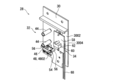
- FIG. 1 is a perspective view of a flash switch according to an embodiment;
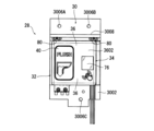
- FIG. 1 is a front view of a flash switch according to an embodiment;
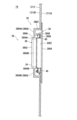
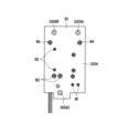
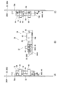
- FIG. FIG. 2 is a cross-sectional view taken along the line AA of FIG. 1; It is a rear view of the flash switch which concerns on embodiment, and shows the state which abbreviate
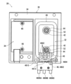
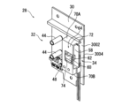
- 1 is a perspective view of a flash switch with a cover and bracket removed;
- FIG. 8 is a front view of FIG. 7;
- (A) is a view on arrow A in FIG.
- FIG. 8 is a view on arrow B in FIG. 8 and (C) is a view on arrow C in FIG.
- FIG. 3 is a perspective view of the flash switch with the cover removed; 11 is a front view of FIG. 10; FIG. (A) is a view on arrow A in FIG. 10, (B) is a view on arrow B in FIG. 8, and (C) is a view on arrow C in FIG. It is a perspective view of a push button.
- FIG. 3 is a perspective view of a bracket; (A) is a front view of the bracket, (B) is a B arrow view of (A), (C) is a C arrow view of (A), (D) is a D arrow view of (C), ( E) is an E arrow view of (A), and (F) is an F arrow view of (A).
- FIG. 3 is a perspective view of a bracket; (A) is a front view of the bracket, (B) is a B arrow view of (A), (C) is a C arrow view of (A), (D) is a D arrow view of (C), (E ) is an E arrow view of (A), and (F) is an F arrow view of (A).
- FIG. 4 is a perspective view of a cover; It is a front view of a cover. It is a rear view of a cover.
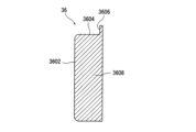
- FIG. 20 is a cross-sectional view taken along line AA of FIG. 19;
- the aircraft lavatory unit 10 includes a body frame 12 , and the interior of the body frame 12 serves as a lavatory 14 .
- the body frame 12 includes a bottom wall 1202, a front wall 1204 rising from the bottom wall 1202, a rear wall 1206 facing the front wall 1204, and a pair of side walls connecting both sides of the rear wall 1206 and both sides of the front wall 1204. 1208.
- a front wall 1204 is provided with an entrance 1210 that is opened and closed by a door, an inner wall 1212 is provided in front of a rear wall 1206 , and a toilet bowl 16 is provided on the bottom wall 1202 via the inner wall 1212 .
- a counter table 18 is provided in the middle of the side wall 1208 in the height direction, and below the counter table 18 is a lower storage section 20 in which a waste box device (not shown) with a fire extinguishing function and fixtures of the restroom 14 are stored.
- the lower storage section 20 can be opened and closed by a plurality of doors 2002 and 2004.
- reference numeral 2006 indicates a garbage inlet.
- an upper storage section 22 which stores fixtures of the restroom 14 such as tissue paper and which is opened and closed by a door 2202 with a mirror.
- a bowl portion 24 is provided at a portion near the front wall 1204 of the counter table 18, and an automatic faucet 26 is provided at a portion of the counter table 18 around the bowl portion 24.
- the flash switch 28 is provided at a portion of the inner wall 1212 positioned above the toilet bowl 16 so that the user can operate it while sitting on the toilet seat.
- the flush switch 28 is operated by the user to actuate a flush valve (electromagnetic valve) (not shown) connected to a water supply pipe (not shown) to flow flush water into the toilet bowl 16 .
- the flash switch 28 includes a single base member 30, a first contact flash switch 32, a second non-contact flash switch 34, and a single cover 36.
- the base member 30 is made of metal, has a rectangular shape in plan view, and is formed with a uniform thickness. can be attached to
- the long side direction of the base member 30 is referred to as the longitudinal direction of the base member 30, and the short side direction of the base member 30 is referred to as the width direction of the base member 30. It has width along the direction.
- One side of the base member 30 is a surface 3002 to which the first flash switch 32, the second flash switch 34 and the cover 36 are attached, and the other side is a rear surface 3004.
- two base member mounting screw insertion holes 3006A and 3006B are provided in the upper portion of the base member 30 at intervals in the width direction. is provided with one base member mounting screw insertion hole 3006C.
- an upper lateral wall 3008 extending over the entire width direction of the base member 30 is erected below the upper two base member mounting screw insertion holes 3006A and 3006B.
- the inner wall 1212 on which the flash switch 28 is provided is formed with a bulging portion 38 having a rectangular frame shape in plan view and bulging toward the restroom 14 side.
- the bulging portion 38 includes an upright wall 3802 that rises in a rectangular frame shape from the inner wall 1212, and an upper wall 3804 that is connected to the entire upper end of the upright wall 3802 and extends in a rectangular frame shape.
- a switch arrangement opening 3806 is provided.
- the longitudinal direction of the base member 30 is parallel to the vertical direction, the upper and lower portions of the base member 30 are superimposed on the outer surface 1212A of the inner wall 1212, and the intermediate portion of the base member 30 is aligned.
- screws (not shown) inserted through the base member mounting screw insertion holes 3006A, 3006B, and 3006C (see FIGS. 2 and 3) are inserted into the inner wall 1212. It is attached to the inner wall 1212 by being screwed into a provided screw hole (not shown).
- the first flash switch 32 and the second flash switch 34 are arranged horizontally on the base member 30 . That is, as shown in FIGS. 3 and 10-12, the first flash switch 32 is provided on approximately half of the surface 3002 of the base member 30 in the horizontal direction, and the second flash switch 34 is provided on the remainder of the base member 30. is provided on approximately half of the surface 3002 of the .
- the first flash switch 32 is a contact-type flash switch operated by a push button 40 (see FIG. 2).
- the first flash switch 32 as shown in FIGS. 44, a lever 46, a microswitch 48, and the like.
- the push button 40 is made of synthetic resin and includes a button body 50 to be pressed by the user of the restroom 14 and a pair of coil spring housing portions 52.
- the button main body 50 includes a main body wall portion 5002 having a vertically elongated rectangular shape, a peripheral wall portion 5004 standing up from the entire circumference of the main body wall portion 5002, and a tip end of the peripheral wall portion 5004 protruding outside the peripheral wall portion 5004 from the entire circumference.
- the pair of coil spring housing portions 52 are places where a part of the coil spring 44 and the tip portion of the guide shaft 42 shown in FIG. It is formed by a pair of cylindrical walls protruding with a space in the direction. 7, 9, 10, and 12, the coil spring 44 is shown in a state of free length.
- the pair of guide shafts 42 protrude from the surface 3002 of the half (left half) of the base member 30 in the horizontal direction, are inserted into the coil spring 44, and are inserted into the coil of the push button 40.
- the push button 40 is attached to the cover 36 so as to be linearly movable between the initial position and the pushed position in the direction in which the front wall 3602 of the cover 36 and the base member 30 (to be described later) face each other. are placed.
- the initial position of the push button 40 is determined by bringing the flange portion 5006 of the push button 40 into contact with the edge of the push button opening 3610 of the cover 36, which will be described later.
- the push button 40 is always biased to the initial position by the coil springs 44 housed in the pair of coil spring housings 52.
- a part of the coil spring 44 in the longitudinal direction is accommodated in the coil spring accommodating portion 52, and both ends of the coil spring 44 are in contact with the bottom wall of the coil spring accommodating portion 52 and the surface 3002 of the base member 30, and are guided.
- the tip of the shaft 42 is positioned inside the coil spring housing portion 52 , and the tip of the guide shaft 42 is positioned away from the bottom wall of the coil spring housing portion 52 .
- the push position of the push button 40 is determined, for example, by contacting the front end of the coil spring accommodating portion 52 with the surface 3002 of the base member 30 .
- the entire longitudinal length of the coil spring 44 is accommodated in the coil spring accommodating portion 52, and both ends of the coil spring 44 are in contact with the bottom wall of the coil spring accommodating portion 52 and the surface 3002 of the base member 30, thereby
- the full length of 42 is located inside the coil spring accommodating portion 52 , and the tip of the guide shaft 42 is located away from the bottom wall of the coil spring accommodating portion 52 even when the push button 40 is in the pushed position.
- the lever 46 is swung by linearly moving the push button 40 from the initial position to the pushed position, and the swung lever 46 moves into the plunger 4804 (which will be described later) of the microswitch 48 (to be described later). 5) is pushed from the projected position to the retracted position, the microswitch 48 is operated.
- the lever 46 is swingably supported with a support shaft 54 as a fulcrum. It is supported by the base member 30 and extends in the width direction of the base member 30 .
- the lever 46 includes four triangular plate portions 4602 integrally swinging about the support shaft 54. The four triangular plate portions 4602 are It has a first portion 4610 located on the push button 40 side from the point supported by the support shaft 54 and a second portion 4612 located on the microswitch 48 side from the point supported by the support shaft 54 .
- the lever 46 When the push button 40 is at its initial position, the lever 46 is also at its initial position.
- a helical coil spring (not shown) for urging the lever 46 to the initial position is provided across the lever 46 and the leg portion 56, and a stopper (not shown) for contacting the lever 46 and positioning the lever 46 to the initial position is the leg portion 56.
- the first portion 4610 is separated from the flange portion 5006 of the push button 40, and the second portion 4612 can contact the tip of the plunger 4804 (see FIG. 5) projected to the projecting position. position.
- the push button 40 is pushed from the initial position to the push-in position, the lever 46 moves from the initial position to the swing position.
- the first portion 4610 is rocked by the flange portion 5006, and the second portion 4612 contacts the tip of the plunger 4804 and pushes the tip of the plunger 4804 to push the plunger 4804 from the projecting position to the retracted position. . Therefore, the first flash switch 32 is activated by the push button 40 .
- the push button 40 is released in this state, the push button 40 returns from the depressed position to the initial position by the biasing force of the coil spring 44, thereby returning the lever 46 to the initial position.
- the microswitch 48 includes a switch body 4802, a plunger 4804, and three connection terminals 4806A, 4806B, and 4806C.
- a waterproof microswitch is used.
- the switch body 4802 has a flat rectangular parallelepiped shape, and is close to the second portion 4612 of the lever 46 with its long side parallel to the width direction of the base member 30. is located on surface 3002 of base member 30 . Specifically, it is attached to the surface 3002 of the base member 30 via a screw N1 (see FIG. 6) inserted through a screw insertion hole (not shown) from the rear surface 3004 .
- Plunger 4804 is provided so as to be retractable from one long side of switch body 4802 . Plunger 4804 is biased to the extended position and is pushed from the extended position to the retracted position by second portion 4612 of lever 46 to actuate microswitch 48 .
- the three connection terminals 4806A, 4806B, 4806C consist of a common terminal 4806A, a normally open terminal 4806B and a normally closed terminal 4806C.
- common terminal 4806A and normally open terminal 4806B are turned on (closed), and common terminal 4806A and normally closed terminal 4806C are turned off (opened).
- the common terminal 4806A and the normally open terminal 4806B are connected to a control section (not shown) via cables (not shown).
- the control unit detects that the common terminal 4806A and the normally open terminal 4806B are turned on, it opens the solenoid valve and flushes the toilet bowl 16 with flush water.
- the second flash switch 34 is a non-contact flash switch and is provided in the remaining widthwise half of the base member 30 in the horizontal direction.
- the second flash switch 34 includes a printed circuit board 58 , an infrared sensor 60 , an indicator LED 62 and a bracket 64 .
- the printed circuit board 58 has a rectangular shape with long sides along the longitudinal direction of the base member 30 .
- both ends of the printed circuit board 58 in the longitudinal direction are separated from the surface 3002 of the base member 30 via a pair of spacers 66 and screws N2 (see FIG. 6). , and a printed circuit board 58 is provided on approximately the remaining half of the base member 30 .
- the infrared sensor 60 is attached to a portion near the bottom of the center of the printed circuit board 58 .
- the infrared sensor 60 emits infrared detection light in a direction opposite to the base member 30 and detects the reflected light of the detection light applied to the fingers of the human body to detect the presence or absence of the fingers of the human body. sensor.
- the infrared sensor 60 detects the finger of the human body, it generates a detection signal and supplies it to the above-described control section via the cable 68 .
- the controller opens the solenoid valve to flush the toilet bowl 16 with flush water. If the cable connecting the microswitch 48 and the controller and the cable 68 connecting the infrared sensor 60 and the controller are separately separated, the microswitch 48 and the infrared sensor 60 can be replaced separately. Therefore, it is advantageous in improving maintainability.
- the indicator LED 62 is mounted on the printed circuit board 58 above and adjacent to the infrared sensor 60 .
- the indicator LED 62 is connected via a cable 68 to the controller.
- the indicator LED 62 notifies the user of the restroom 14 of the state of detection of the human body by the infrared sensor 60 .
- the controller causes the indicator LED 62 to emit light at low luminance when the infrared sensor 60 does not detect the human body, and causes the indicator LED 62 to emit light at high luminance when the infrared sensor 60 detects the human body. to emit light.
- the emission color of the indicator LED 62 is, for example, blue, the emission color is not limited.
- the bracket 64 is provided on approximately half of the base member 30 on which the second flash switch 34 is provided.
- the bracket 64 includes a pair of leg portions 70A and 70B and a body plate portion 72.
- the body plate portion 72 is supported by a pair of leg portions 70A and 70B, faces the base member 30, and covers the printed circuit board 58.
- the body plate portion 72 has a rectangular shape in a plan view, and a rectangular opening 74 is formed at a location facing the infrared sensor 60 and the indicator LED 62 .
- a portion of the body plate portion 72 around the opening 74 is a portion that abuts on the periphery of a transparent plate 76 attached to the cover 36, which will be described later.
- One of the pair of legs 70A and 70B is the first leg 70A and the other is the second leg 70B.
- the first leg portion 70A protrudes from one longitudinal end of the main body plate portion 72 toward the base member 30, and the tip thereof can contact the surface 3002 of the base member 30.
- the second leg portion 70 ⁇ /b>B protrudes from the other longitudinal end of the main body plate portion 72 toward the base member 30 , and the tip of the second leg portion 70 ⁇ /b>B contacts the surface 3002 of the base member 30 .
- the second leg portion 70B is formed with a pair of screw holes 7002 penetrating in its extending direction.
- the bracket 64 is attached to the base member 30 by screwing a screw N3 (see FIG. 6) inserted through the screw insertion hole into each screw hole 7002. It abuts surface 3002 .
- the cover 36 covers the first flash switch 32 and the second flash switch 34 .
- the cover 36 includes a front wall 3602, a peripheral wall 3604, a flange wall 3606, a partition wall 3608, and a transparent plate 76.
- the width and length of the base member 30 are It has a width and length corresponding to
- the front wall 3602 extends substantially vertically when the cover 36 is in use, and the front wall 3602 is positioned opposite the base member 30 .
- the front wall 3602 is provided with a push button opening 3610 and a sensor opening 3612 arranged side by side in the width direction of the front wall 3602 .
- the push button opening 3610 is a portion where the body wall portion 5002 of the push button 40 is exposed and the push button 40 can be pressed.
- the push button opening 3610 is formed with an outline that is one size larger than the outline of the push button 40, and the surface of the main body wall portion 5002 in the initial position of the push button 40 faces the front wall so that the push button 40 can be easily pressed. It is positioned at a location that slightly protrudes from 3602 .
- the sensor opening 3612 is provided corresponding to the infrared sensor 60 and the indicator LED 62 and has a rectangular shape that is one size smaller than the opening 74 of the bracket 64 . In FIG.
- reference numeral 78 denotes a portion of the front wall 3602 near the sensor opening 3612 to indicate that the second flash switch 34 is a non-contact sensor, in other words, the flash switch 28 that is operated by waving a hand over it. shows the display of the hand formed in the
- the peripheral wall 3604 protrudes from the periphery of the front wall 3602 toward the base member 30 , and the projecting end of the peripheral wall 3604 abuts the surface 3002 of the base member 30 .
- the perimeter wall 3604 includes a top wall 3604A, a bottom wall 3604B, and a pair of side walls 3604C, 3604D.
- the upper wall 3604A protrudes from the upper end of the front wall 3602 toward the base member 30
- the lower wall 3604B protrudes from the lower end of the front wall 3602 toward the base member 30
- the pair of side walls 3604C and 3604D extend from the front wall. 3602 projecting from both sides toward the base member 30 .
- the side wall 3604D on the side of the second flash switch 34 has a first wall portion 3620 projecting from the front wall 3602 and a front wall It is composed of an intermediate wall 3622 that protrudes in the width direction of 3602 and a second wall portion 3624 that protrudes from the tip of the intermediate wall 3622 toward the base member 30 and contacts the base member 30 .
- the second wall portion 3624 extends in the longitudinal direction of the front wall 3602, and the second wall portion 3624 abuts the base member 30 over its entire length.
- the flange wall 3606 extends from the tip of the top wall 3604A to the tip of the side wall 3604C of the pair of side walls 3604C and 3604D on the first flash switch 32 side to the outside of the cover 36.
- the flange wall 3606 abuts the surface 3002 of the base member 30 over its entire length. Therefore, the upper wall 3604A and the side wall 3604C on the side of the first flash switch 32 are in contact with the base member 30 via the flange wall 3606. As shown in FIG.
- the bottom wall 3604B abuts on the base member 30 over its entire length.
- a portion of the flange wall 3606 provided at the tip of the upper wall 3604A is provided with a screw insertion hole 3630 and a female screw member 80 (see FIG. 3) near both ends in the extending direction of the flange wall 3606.
- screws N4 inserted through screw holes (not shown) provided in the base member 30 corresponding to the screw holes 3630 are screwed into the female screw members 80, respectively, so that the cover 36 is It is attached to the base member 30 .
- the partition wall 3608 is provided so as to protrude from the inner surface of the front wall 3602 .
- the partition wall 3608 extends in a direction orthogonal to the direction in which the first flash switch 32 and the second flash switch 34 are arranged, and divides the inside of the cover 36 into a first space S1 in which the first flash switch 32 is accommodated. , and a second space S2 in which the second flash switch 34 is accommodated.
- the partition wall 3608 extends between the peripheral walls 3604 facing each other (between the upper wall 3604A and the lower wall 3604B), and the end of the partition wall 3608 abuts the base member 30 over its entire length.
- the first space S1 includes a half portion of the front wall 3602, a half portion of the upper wall 3604A, a half portion of the lower wall 3604B, a side wall 3604C on the side of the first flash switch 32, a partition wall 3608, and a base member 30.
- the second space S2 consists of the remaining half of the front wall 3602, the remaining half of the upper wall 3604A, the remaining half of the lower wall 3604B, the side wall 3604D on the second flash switch 34 side, and the partition wall 3608.
- This partition wall 3608 also functions as a rib that reinforces the front wall 3602 of the cover 36 .
- the transparent plate 76 is made of a transparent synthetic resin material that transmits infrared rays.
- the transparent plate 76 has a rectangular plate shape with an outline larger than the sensor opening 3612 and is detachably attached to the sensor opening 3612 from the inner surface of the front wall 3602 of the cover 36 .
- the transparent plate 76 includes a substantially square plate-shaped substrate portion 7602 and a bulging portion 7604 that is fitted from the substrate portion 7602 into the bulging sensor opening 3612 . ing.
- the tip surface of the bulging portion 7604 and the surface of the front wall 3602 are located on the same plane when the bulging portion 7604 is fitted in the sensor opening 3612 .
- An opening 74 of the main body plate portion 72 of the bracket 64 is provided around the transparent plate 76 positioned outside the sensor opening 3612 of the cover 36 , more specifically, at a portion of the substrate portion 7602 positioned outside the bulging portion 7604 . (see FIG. 15) are in contact with each other. Further, in this embodiment, the inner surface of the substrate portion 7602 is flush with the inner surface of the front wall 3602 when the transparent plate 76 is attached to the sensor opening 3612 of the cover 36 .
- the flash switch 28 has the cover 36 by pressing the upper and lower portions of the base member 30 against the outer surface 1212A of the inner wall 1212 and fastening screws (not shown) from the outer surface 1212A side, as described above.
- the entire area of the front wall 3602 is exposed to the interior of the restroom 14 through the switch arrangement opening 3806 of the bulging portion 38 of the inner wall 1212 . Therefore, the operation of the push button 40 of the first flash switch 32 and the detection of the finger by the infrared sensor 60 of the second flash switch 34 are ensured.
- the front wall 3602 of the cover 36 is surrounded by a top wall 3804 extending like a rectangular frame.
- reference numeral 3804A indicates the upper portion of the upper wall 3804 extending like a rectangular frame.
- the upper portion 3804A covers the front of a flange wall 3606 projecting from the tip of the upper wall 3604A of the cover 36.
- reference numeral 3804B denotes a lower portion of the upper wall 3804 extending like a rectangular frame.
- the lower portion 3804B includes the portion of the microswitch 48 exposed from below the lower wall 3604B of the cover 36, the cable portion (not shown) drawn out from the microswitch 48, the infrared sensor 60, and the indicator LED 62. A portion of the cable 68 is covered. By hiding the flange wall 3606, the female screw member 80 that attaches the flange wall 3606 to the base member 30, the microswitch 48 portion, the cables (not shown) and the cable 68 portion by the portions 3804A, 3804B of the bulging portion 38, 14 aesthetics are secured.
- the flash switch 28 is attached by abutting the upper and lower portions of the base member 30 against the outer surface 1212A of the inner wall 1212 and screwing them from the outer surface 1212A side has been described.
- the rear surface 3004 of the aircraft lavatory unit 10 may be attached against, for example, the inner surface 1212B of the inner wall 1212 of the aircraft lavatory unit 10 .
- the heads of mounting screws N1, N2, N3, and N4 for mounting members such as the microswitch 48, the printed circuit board 58, the bracket 64, and the cover 36 to the base member 30 are located on the inner surface 1212B of the inner wall 1212.
- the heads of the screws N1, N2, N3, N4 do not protrude from the rear surface 3004 of the base member 30 so as not to interfere with the . Therefore, if a counterbore is provided on the back surface 3004 side of the screw insertion hole of the base member 30 and countersunk screws are used as the mounting screws N1, N2, N3 and N4 of each part, the mounting screws N1, N2, Since the heads of N3 and N4 do not protrude from the back surface 3004 of the base member 30, the back surface 3004 of the base member 30 can be reliably and stably brought into contact with the wall surface of the aircraft lavatory unit 10. It is advantageous for easy installation on the wall surface.
- the flash switch 28 comprises a first contact flash switch 32 operated by a push button 40 and a second non-contact flash switch 34 having a human body sensor.
- 32 and second flash switch 34 are mounted on a single base member 30 and covered by a single cover 36 . Therefore, since the contactless second flash switch 34 can be used, it is of course advantageous in terms of preventing infectious diseases, and even if the contactless second flash switch 34 fails, Also, by using the contact-type first flush switch 32, it is possible to avoid impairing the flushing function of the toilet bowl 16 of the aircraft lavatory unit 10, which is advantageous in ensuring user convenience. Become.
- the number of parts of the aircraft lavatory unit 10 can be reduced compared to the case where two types of flash switches, the first contact flash switch 32 and the second non-contact flash switch 34, are provided at separate locations. This is advantageous in improving the efficiency of assembly work and reducing the weight of the aircraft lavatory unit 10 .
- the first flash switch 32 is provided in approximately half of the base member 30 in the horizontal direction
- the second flash switch 34 is provided in approximately the remaining half of the base member 30. This is advantageous in terms of improving the appearance and usability of the flash switch 28, and is advantageous in efficiently laying out the components of the flash switch 28.
- FIG. 1 is advantageous in terms of improving the appearance and usability of the flash switch 28, and is advantageous in efficiently laying out the components of the flash switch 28.
- the cover 36 has a front wall 3602 facing the base member 30 and having the push button 40 disposed thereon, and a peripheral wall 3604 projecting from the periphery of the front wall 3602 toward the base member 30.
- the first flash switch 32 extends in the direction orthogonal to the direction in which the first flash switch 32 and the second flash switch 34 are arranged.
- a partition wall 3608 is provided to partition a first space S1 in which the second flash switch 34 is accommodated and a second space S2 in which the second flash switch 34 is accommodated.
- the partition wall 3608 blocks dust, the waterproofness and dustproofness of the second flash switch 34 can be enhanced, which is advantageous in improving the durability of the second flash switch 34 . In particular, some passengers wash their feet in the toilet bowl 16 depending on the route.
- the partition wall 3608 also functions as a reinforcing rib, the strength and rigidity of the cover 36 can be increased.
- the partition wall 3608 extends between the peripheral walls 3604 facing each other (between the upper wall 3604A and the lower wall 3604B), and the end of the partition wall 3608 abuts the base member 30 over its entire length. Therefore, it is more advantageous in ensuring the function of the partition wall 3608 as a reinforcing rib, and in enhancing the strength and rigidity of the cover 36 . Therefore, even if the user of the aircraft lavatory unit 10 staggers and comes into contact with the cover 36 due to severe vibration when the aircraft enters the air pocket, the cover 36 can be prevented from being damaged or deformed.
- the ability to protect the switch 32 and the second flush switch 34 is advantageous in ensuring the flush function of the toilet 16 of the aircraft lavatory unit 10 . Even if the user operates the first flash switch 32 or the second flash switch 34 with the sole of the shoe and an excessive load is applied to the cover 36, the partition wall 3608 functions as a reinforcing rib in the same manner as described above. As a result, the cover 36 can be prevented from being damaged or deformed, and the first flush switch 32 and the second flush switch 34 can be protected.
- the human body sensor is the infrared sensor 60
- the second flash switch 34 includes a printed circuit board 58 attached to approximately half of the base member 30 and supporting the infrared sensor 60.
- a bracket 64 having a pair of leg portions 70A and 70B standing from a portion of the base member 30 straddling the printed circuit board 58 in the direction and a body plate portion 72 supported by the pair of leg portions 70A and 70B and covering the printed circuit board 58 is provided.
- a sensor opening 3612 and an opening 74 are provided in the front wall 3602 and the body plate portion 72 facing the infrared sensor 60, respectively.
- a transparent plate 76 having a larger contour than the opening 74 of the main body plate portion 72 that transmits infrared rays is attached to the sensor opening 3612 of the front wall 3602 and is positioned outside the sensor opening 3612. A portion around the opening 74 of the main body plate portion 72 is in contact with the periphery of the transparent plate 76 . Therefore, when the transparent plate 76 is damaged or deteriorated over time, only the transparent plate 76 can be easily replaced, which is advantageous in improving the maintainability of the flash switch 28 .
- the portion around the opening 74 of the main body plate portion 72 of the bracket 64 abuts against the transparent plate 76 located outside the sensor opening 3612 of the cover 36, when the aircraft enters the air pocket, Even if the user of the aircraft lavatory unit 10 staggers due to strong vibrations and comes into contact with the transparent plate 76 , the transparent plate 76 does not come off from the sensor opening 3612 of the cover 36 . Therefore, it is possible to prevent the infrared sensor 60 or the printed circuit board 58 from being damaged by the transparent plate 76 coming off, which is advantageous in ensuring the flushing function of the toilet bowl 16 of the aircraft lavatory unit 10 .
- the transparent plate 76 of the cover 36 falls out of the sensor opening 3612 of the cover 36 in the same manner as described above. Since the infrared sensor 60 or the printed circuit board 58 can be prevented from being damaged by the fallen transparent plate 76, it is advantageous in ensuring the flushing function of the toilet bowl 16 of the aircraft lavatory unit 10.
- the first flash switch 32 includes a microswitch 48 having a plunger 4804, and the push button 40 faces the front wall 3602 and the base member 30 between the initial position and the depressed position.
- the first flash switch 32 is oscillated by a coil spring 44 that biases the push button 40 to the initial position and the linear movement of the push button 40 from the initial position to the depressed position. and a lever 46 for pressing the plunger 4804 . Therefore, for example, even if an existing single contact flash switch uses an oscillating push button instead of a linear movement type as in the present embodiment, the existing flash switch , first and second flash switches 32 and 34, the microswitches of the existing flash switches can be used. Therefore, when replacing with the flash switch 28 having the first and second flash switches 32 and 34, it is possible to reduce the number of parts of the flash switch 28 and to reduce the cost.
- Aircraft Lavatory Unit 12 Body Frame 1202 Bottom Wall 1204 Front Wall 1206 Rear Wall 1208 Side Wall 1210 Doorway 1212 Inner Wall 1212A Outer Surface of Inner Wall 1212B Inner Surface of Inner Wall 14 Lavatory Room 16 Toilet Bowl 18 Counter Table 20 Lower Storage Sections 2002, 2004 Door 2006 Garbage inlet 22 Upper housing portion 2202 Door 24 Bowl portion 26 Automatic faucet 28 Flush switch 30 Base member 3002 Front surface 3004 Rear surface 3006A, 3006B, 3006C Base member mounting screw insertion hole 3008 Upper lateral wall 32 First flush switch 34 Second flush switch 36 cover 3602 front wall 3604 peripheral wall 3604A upper wall 3604B lower walls 3604C, 3604D side wall 3606 flange wall 3608 partition wall 3610 push button opening 3612 sensor opening 3620 first wall portion 3622 intermediate wall 3624 second wall portion 3630 screw insertion hole 76 Transparent plate 38 Swelling portion 3802 Upright wall 3804 Upper wall 3806 Switch arrangement opening 40 Push button 42 Guide shaft 44 Coil spring 46 Lever 4602 Triangular plate portion 4610 First portion
Landscapes
- Engineering & Computer Science (AREA)
- Aviation & Aerospace Engineering (AREA)
- Health & Medical Sciences (AREA)
- Life Sciences & Earth Sciences (AREA)
- Hydrology & Water Resources (AREA)
- Public Health (AREA)
- Water Supply & Treatment (AREA)
- Push-Button Switches (AREA)
- Sanitary Device For Flush Toilet (AREA)
- Switches Operated By Changes In Physical Conditions (AREA)
Abstract
Description
フラッシュバルブ式トイレは、便器がフラッシュバルブを介して給水管(水道管)に直接接続され、化粧室の壁面などに設けられたフラッシュスイッチを使用者が操作することによってフラッシュバルブが開弁され水洗水が便器に流されるものである。
従来、フラッシュスイッチとして、使用者が手指で押圧操作する押し釦で作動する接触式のフラッシュスイッチ(特許文献1参照)と、使用者の人体の一部(手指)を非接触で検出する人体センサを用いた非接触式のフラッシュスイッチ(特許文献2参照)とが知られている。
しかしながら、非接触式のフラッシュスイッチを採用した場合、非接触式のフラッシュスイッチが故障すると、便器の水洗機能が損なわれることが懸念される。
そこで、非接触式のフラッシュスイッチと接触式のフラッシュスイッチとの2種類のフラッシュスイッチを化粧室の壁面に設けることで、非接触式のフラッシュスイッチが故障しても接触式のフラッシュスイッチを操作することで便器の水洗機能を確保することが考えられる。
しかしながら、2種類のフラッシュスイッチを航空機用化粧室ユニットの化粧室の壁面の別々の箇所に設けた場合、航空機用化粧室ユニットの部品点数が増加し、それらフラッシュスイッチの組み付け作業効率が低下し、また、航空機用化粧室ユニットの軽量化を図る上で不利となる。
本発明は前記事情に鑑み案出されたものであって、本発明の目的は、2種類のフラッシュスイッチを備える航空機用化粧室ユニットの部品点数を削減し、組み付け作業効率を高め、航空機用化粧室ユニットの軽量化を図る上で有利な航空機用化粧室ユニットのフラッシュスイッチを提供することにある。
したがって、非接触式の第2フラッシュスイッチを用いることができるため、感染症予防を図る上で有利となることは無論のこと、非接触式の第2フラッシュスイッチが故障した場合であっても、接触式の第1フラッシュスイッチを用いることにより、航空機用化粧室ユニットの水洗機能が損なわれる事態を回避することができ、使用者の利便性を確保する上で有利となる。
また、接触式の第1フラッシュスイッチと非接触式の第2フラッシュスイッチとを別々の箇所に設ける場合に比べて航空機用化粧室ユニットの部品点数を削減し、組み付け作業効率を高め、航空機用化粧室ユニットの軽量化を図る上で有利となる。
次に図面を参照して本実施の形態について説明する。
まず、本発明に係るフラッシュスイッチが適用される航空機用化粧室ユニットについて説明する。
図1に示すように、航空機用化粧室ユニット10は躯体フレーム12を備え、躯体フレーム12の内部が化粧室14となっている。
躯体フレーム12は、底壁1202と、底壁1202から起立する正面壁1204と、正面壁1204に対向する背面壁1206と、背面壁1206の両側と正面壁1204の両側を接続する一対の側面壁1208とを備えている。
正面壁1204に、扉により開閉される出入口1210が設けられ、背面壁1206の前方に内壁1212が設けられ、便器16は内壁1212を介して底壁1202上に設けられている。
なお、図1では一対の側面壁1208のうちの一方と、出入口1210を開閉する扉が省略されている。
側面壁1208の高さ方向の中間にカウンターテーブル18が設けられ、カウンターテーブル18の下方は、消火機能付きの不図示のごみ箱装置や化粧室14の備品などが収納される下部収納部20となっており、下部収納部20は複数の扉2002、2004により開閉可能であり、図1において、符号2006はごみ投入口を示している。
カウンターテーブル18の上方は、ティッシュペーパーなどの化粧室14の備品が収納され鏡付きの扉2202により開閉される上部収納部22となっている。
カウンターテーブル18の正面壁1204寄りの箇所にボウル部24が設けられ、ボウル部24の周囲のカウンターテーブル18の箇所に自動水栓26が設けられている。
フラッシュスイッチ28は、使用者が操作することにより、不図示の給水管に接続された不図示のフラッシュバルブ(電磁弁)を作動させて便器16に水洗水を流すものである。
図3、図4、図6に示すように、ベース部材30は、金属製であり、平面視長方形状を呈し均一の厚さで形成され、図4に示すように、化粧室14の内壁1212に取り付けられる。
なお、以下では、ベース部材30の長辺方向をベース部材30の長手方向、ベース部材30の短辺方向をベース部材30の幅方向といい、ベース部材30は長手方向に沿った長さと、幅方向に沿った幅を有している。
ベース部材30が化粧室14の内壁1212に取り付けられた状態で、ベース部材30の長手方向は上下方向に延在し、ベース部材30の幅方向は水平方向に延在している。
ベース部材30の一方の面は第1フラッシュスイッチ32、第2フラッシュスイッチ34、カバー36が取り付けられる表面3002であり、他方の面は背面3004である。
図3、図6に示すように、ベース部材30の上部には幅方向に間隔をおいて2つのベース部材取り付け用ねじ挿通孔3006A、3006Bが設けられ、ベース部材30の下部の幅方向の中央には1つのベース部材取り付け用ねじ挿通孔3006Cが設けられている。
また、ベース部材30の表面3002で、上部の2つのベース部材取り付け用ねじ挿通孔3006A、3006Bの下方にはベース部材30の幅方向の全長にわたって延在する上部横壁3008が立設されている。
膨出部38は、内壁1212から矩形枠状に起立する起立壁3802と、起立壁3802の上端全周に接続され矩形枠状に延在する上壁3804とを備え、上壁3804の内側がスイッチ配設用開口3806となっている。
本実施の形態では、図4に示すように、ベース部材30は、長手方向を上下方向に平行させ、ベース部材30の上部と下部を内壁1212の外面1212Aに重ね合わせ、ベース部材30の中間部を上壁3804およびスイッチ配設用開口3806に対向させた状態で、ベース部材取り付け用ねじ挿通孔3006A、3006B、3006C(図2、図3参照)に挿通された不図示のねじが内壁1212に設けられた不図示のねじ孔に螺合されることで内壁1212に取り付けられる。
すなわち、図3、図10-図12に示すように、第1フラッシュスイッチ32は、水平方向においてベース部材30の表面3002のほぼ半部に設けられ、第2フラッシュスイッチ34はベース部材30の残りの表面3002のほぼ半部に設けられている。
図13、図14に示すように、押し釦40は合成樹脂製であり、化粧室14の使用者により押圧される釦本体50と、一対のコイルスプリング収容部52とを備えている。
釦本体50は、上下方向に細長の長方形状を呈する本体壁部5002と、本体壁部5002の全周から起立する周壁部5004と、周壁部5004の先端全周から周壁部5004の外側に突出するフランジ部5006とを備えている。
本体壁部5002の表面には、フラッシュスイッチ28であることを示す文字5010と、便器16から水が流れる表示5012とが形成されている。
一対のコイルスプリング収容部52は、図5に示すコイルスプリング44の一部とガイド軸42の先部が収容される箇所であり、本体壁部5002の背面の幅方向の中央で、背面の長手方向に間隔をおいて突設された一対の円筒壁で形成されている。
なお、図7、図9、図10、図12においてコイルスプリング44は自由長の状態を描いている。
図2、図3に示すように、押し釦40は、初期位置と押し込み位置との間で、後述するカバー36の正面壁3602とベース部材30とが対向する方向に直線移動可能にカバー36に配置されている。
押し釦40の初期位置は、押し釦40のフランジ部5006が後述するカバー36の押し釦用開口3610の縁部に当接することで決定される。
図5、図7-図9に示すように、押し釦40は、一対のコイルスプリング収容部52に収容されたコイルスプリング44によって初期位置に常時付勢されている。
この状態で、コイルスプリング44の長手方向の一部はコイルスプリング収容部52に収容され、コイルスプリング44の両端はコイルスプリング収容部52の底壁とベース部材30の表面3002とに接触し、ガイド軸42の先部はコイルスプリング収容部52の内部に位置し、ガイド軸42の先端はコイルスプリング収容部52の底壁から離れた箇所に位置している。
この状態で、コイルスプリング44の長手方向の全長はコイルスプリング収容部52に収容され、コイルスプリング44の両端はコイルスプリング収容部52の底壁とベース部材30の表面3002とに接触し、ガイド軸42の全長部分はコイルスプリング収容部52の内部に位置し、この押し釦40の押し込み位置でも、ガイド軸42の先端はコイルスプリング収容部52の底壁から離れた箇所に位置している。
図7、図8、図9(C)に示すように、レバー46は、支軸54を支点として揺動可能に支持され、支軸54は、その長手方向の両端が脚部56を介してベース部材30で支持され、ベース部材30の幅方向に延在している。
図5、図8に示すように、レバー46は、支軸54を支点として一体的に揺動する4つの三角形状の板部4602を含んで構成され、4つの三角形状の板部4602は、支軸54で支持された箇所から押し釦40側に位置する第1部分4610と、支軸54で支持された箇所からマイクロスイッチ48側に位置する第2部分4612とを有している。
なお、レバー46を初期位置に付勢する不図示の弦巻コイルスプリングがレバー46と脚部56とにわたって設けられ、レバー46に当接しレバー46を初期位置に位置決めする不図示のストッパが脚部56に設けられている。
レバー46の初期位置では、第1部分4610は押し釦40のフランジ部5006から離間しており、第2部分4612は突出位置に突出されたプランジャ4804(図5参照)の先端に当接可能な位置となっている。
一方、押し釦40が初期位置から押し込み位置に押し込まれると、レバー46は初期位置から揺動位置となる。
レバー46の揺動位置では、第1部分4610がフランジ部5006によって揺動され、第2部分4612はプランジャ4804の先端に当接しプランジャ4804の先端を押し込んでプランジャ4804を突出位置から没入位置に押し込む。
したがって、第1フラッシュスイッチ32は、押し釦40で作動する。
また、この状態で押し釦40から手を離すと、押し釦40がコイルスプリング44の付勢力によって押し込み位置から初期位置に復帰し、これによりレバー46は初期位置に復帰する。
図5、図7-図9に示すように、スイッチ本体4802は、扁平な直方体状を呈し、長辺をベース部材30の幅方向と平行させた状態でレバー46の第2部分4612に近接してベース部材30の表面3002に配置されている。詳細には、背面3004から不図示のねじ挿通孔を挿通したねじN1(図6参照)を介してベース部材30の表面3002に取り付けられている。
プランジャ4804は、スイッチ本体4802の一方の長辺から出没可能に設けられている。
プランジャ4804は、突出位置に付勢されており、レバー46の第2部分4612によって突出位置から没入位置に押し込まれることでマイクロスイッチ48が作動する。
プランジャ4804が没入位置に押し込まれると、共通端子4806Aと常開端子4806Bとがオン(閉成)され、共通端子4806Aと常閉端子4806Cとがオフ(開成)される。
本実施の形態では、共通端子4806Aと常開端子4806Bとが不図示のケーブルを介して不図示の制御部に接続されている。
制御部は、共通端子4806Aと常開端子4806Bとがオンしたことを検知すると、電磁弁を開弁させて便器16に水洗水を流す。
第2フラッシュスイッチ34は、プリント基板58と、赤外線センサ60と、インジケータLED62と、ブラケット64とを含んで構成されている。
図7、図8に示すように、プリント基板58は、ベース部材30の長手方向と沿った長辺を有する長方形状を呈している。
図9(C)に示すように、プリント基板58の長手方向の両端は、一対のスペーサ66とねじN2(図6参照)を介してベース部材30の表面3002から離間した箇所に、ベース部材30と平行して取り付けられ、プリント基板58は、ベース部材30の残りのほぼ半部に設けられている。
赤外線センサ60は、赤外線からなる検知光をベース部材30と反対方向に向けて照射すると共に、人体の手指に照射された検知光の反射光を検出することで人体の手指の有無を検出する人体センサである。
赤外線センサ60は、人体の手指を検出すると、検出信号を生成しケーブル68を介して前述した制御部に供給する。
制御部は、検出信号を受け付けると、電磁弁を開弁させて便器16に水洗水を流す。
なお、マイクロスイッチ48と制御部を接続するケーブルと、赤外線センサ60と制御部とを接続するケーブル68を独立分離しておくと、マイクロスイッチ48と赤外線センサ60とを別々に交換することができるため、メンテナンス性を高める上で有利となる。
インジケータLED62は、制御部にケーブル68を介して接続されている。
インジケータLED62は、赤外線センサ60による人体の検出状態を化粧室14の使用者に対して報知するものである。
本実施の形態では、制御部は、赤外線センサ60による人体の検出がされていない場合は、インジケータLED62を低輝度で発光させ、赤外線センサ60によって人体が検出された場合は、インジケータLED62を高輝度で発光させる。
インジケータLED62の発光色は例えば青色であるが、発光色は限定されるものではない。
ブラケット64は、一対の脚部70A、70Bと、本体板部72とを備えている。
本体板部72は、一対の脚部70A、70Bで支持されベース部材30に対向しプリント基板58を覆うものである。
本体板部72は、平面視長方形状を呈し、赤外線センサ60およびインジケータLED62に対向する箇所に、矩形状の開口74が形成されている。
本体板部72の開口74の周囲の箇所は、後述するカバー36に取り付けられた透明板76の周囲に当接する箇所となっている。
図10-図12に示すように、第1脚部70Aは、本体板部72の長手方向の一端からベース部材30側に突設され、その先端はベース部材30の表面3002に当接可能に設けられている。
第2脚部70Bは、本体板部72の長手方向の他端からベース部材30側に突設され、その先端がベース部材30の表面3002に当接している。
図11に示すように、第2脚部70Bは、その延在方向に貫通する一対のねじ孔7002が形成され、それら一対のねじ孔7002に対応してベース部材30に形成された不図示のねじ挿通孔を挿通したねじN3(図6参照)が各ねじ孔7002に螺合することで、ブラケット64がベース部材30に取り付けられ、この状態で第1脚部70Aの先端はベース部材30の表面3002に当接している。
図17-図19に示すように、カバー36は、正面壁3602と、周壁3604と、フランジ壁3606と、隔壁3608と、透明板76とを含んで構成され、ベース部材30の幅と長さに対応した幅と長さを有している。
正面壁3602は、カバー36の使用状態でほぼ鉛直面上を延在し、正面壁3602は、ベース部材30に対向した箇所に位置している。
正面壁3602には、押し釦用開口3610と、センサ用開口3612とが正面壁3602の幅方向に並べられて設けられている。
押し釦用開口3610は、押し釦40の本体壁部5002を露出させ、押し釦40の押圧操作を可能とする箇所である。
押し釦用開口3610は、押し釦40の輪郭よりも一回り大きい輪郭で形成され、押し釦40を押圧操作しやすいように、押し釦40の初期位置において本体壁部5002の表面が、正面壁3602よりも若干突出する箇所に位置している。
センサ用開口3612は、赤外線センサ60およびインジケータLED62に対応して設けられ、ブラケット64の開口74よりも一回り小さい矩形状を呈している。
図18において、符号78は、第2フラッシュスイッチ34が非接触センサ、言い換えると、手をかざすことで動作するフラッシュスイッチ28であることを示すためにセンサ用開口3612の近傍の正面壁3602の箇所に形成された手の表示を示す。
詳細に説明すると、図18に示すように、周壁3604は、上壁3604Aと、下壁3604Bと、一対の側壁3604C、3604Dとを備えている。
上壁3604Aは、正面壁3602の上端からベース部材30側に突設され、下壁3604Bは、正面壁3602の下端からベース部材30側に突設され、一対の側壁3604C、3604Dは、正面壁3602の両側からベース部材30側に突設されている。
図17に示すように、一対の側壁3604C、3604Dのうち、第2フラッシュスイッチ34側の側壁3604Dは、正面壁3602から突出する第1壁部3620と、第1壁部3620の先端から正面壁3602の幅方向に突出する中間壁3622と、中間壁3622の先端からベース部材30方向に突出しベース部材30に当接する第2壁部3624とで構成されている。
第2壁部3624は正面壁3602の長さ方向に延在しており、第2壁部3624はその全長にわたってベース部材30に当接している。
したがって、上壁3604Aと、第1フラッシュスイッチ32側の側壁3604Cとはフランジ壁3606を介してベース部材30に当接している。
上壁3604Aの先端に設けられたフランジ壁3606の部分には、フランジ壁3606の延在方向の両端寄りの箇所にねじ挿通孔3630と、雌ねじ部材80(図3参照)とがそれぞれ設けられている。
したがって、図6に示すように、ねじ挿通孔3630に対応するベース部材30の箇所に設けられた不図示のねじ挿通孔を挿通したねじN4が雌ねじ部材80にそれぞれ螺合することでカバー36はベース部材30に取り付けられている。
隔壁3608は、第1フラッシュスイッチ32と第2フラッシュスイッチ34とが並べられた方向と直交する方向に延在し、カバー36の内部を、第1フラッシュスイッチ32が収容される第1空間S1と、第2フラッシュスイッチ34が収容される第2空間S2とに区画しており、正面壁3602と反対に位置する隔壁3608の端部はその全長にわたってベース部材30に当接している。
言い換えると、隔壁3608は、互いに対向する周壁3604間(上壁3604A、下壁3604B間)にわたって延在しており、隔壁3608の端部はその全長にわたってベース部材30に当接している。
すなわち、第1空間S1は、正面壁3602の半部と、上壁3604Aの半部と、下壁3604Bの半部と、第1フラッシュスイッチ32側の側壁3604Cと、隔壁3608と、ベース部材30の表面3002とによって囲まれた空間である。
第2空間S2は、正面壁3602の残りの半部と、上壁3604Aの残りの半部と、下壁3604Bの残りの半部と、第2フラッシュスイッチ34側の側壁3604Dと、隔壁3608と、ベース部材30の表面3002とによって囲まれた空間である。
この隔壁3608は、カバー36の正面壁3602を補強するリブとしても機能している。
透明板76は、センサ用開口3612よりも大きい輪郭の矩形板状を呈し、カバー36の正面壁3602の内面からセンサ用開口3612に着脱可能に取り付けられている。
詳細には、図19に示すように、透明板76は、ほぼ正方形の板状の基板部7602と、基板部7602から膨出しセンサ用開口3612にはめ込まれる膨出部7604とを含んで構成されている。
膨出部7604がセンサ用開口3612にはめ込まれた状態で膨出部7604の先端面と正面壁3602の表面とは同一面上に位置している。
カバー36のセンサ用開口3612の外側に位置する透明板76の周囲の箇所に、詳細には、膨出部7604の外側に位置する基板部7602の箇所にブラケット64の本体板部72の開口74(図15参照)の周囲の箇所が当接している。
また、本実施の形態では、カバー36のセンサ用開口3612に透明板76が取り付けられた状態で、基板部7602の内面は正面壁3602の内面と同一面上に位置している。
そのため、第1フラッシュスイッチ32の押し釦40の操作、第2フラッシュスイッチ34の赤外線センサ60による手指の検出を確実に行えるように図られている。
図4において、符号3804Aは、矩形枠状に延在する上壁3804の上側部分を示す。この上側部分3804Aは、カバー36の上壁3604Aの先端から突設されたフランジ壁3606の前方を覆っている。
また、符号3804Bは、矩形枠状に延在する上壁3804の下側部分を示す。この下側部分3804Bは、カバー36の下壁3604Bの下方から露出するマイクロスイッチ48の部分と、マイクロスイッチ48から引き出された不図示のケーブルの部分と、赤外線センサ60、インジケータLED62から引き出されたケーブル68の部分とを覆っている。
膨出部38の部分3804A、3804Bによって、フランジ壁3606、フランジ壁3606をベース部材30に取り付ける雌ねじ部材80、マイクロスイッチ48の部分、不図示のケーブルおよびケーブル68の部分を隠すことにより、化粧室14の美観が確保されている。
この場合は、ベース部材30に対してマイクロスイッチ48、プリント基板58、ブラケット64、カバー36などの部材を取り付けるための取り付け用のねじN1、N2、N3、N4の頭部が内壁1212の内面1212Bに干渉しないように、それらねじN1、N2、N3、N4の頭部がベース部材30の背面3004から突出しないようにすることが好ましい。
そのため、ベース部材30のねじ挿通孔の背面3004側に座ぐりを設けると共に、各部の取り付け用のねじN1、N2、N3、N4として皿ねじを用いるようにすると、取り付け用のねじN1、N2、N3、N4の頭部が、ベース部材30の背面3004から突出しないので、ベース部材30の背面3004を航空機用化粧室ユニット10の壁面に確実に安定して当て付けることができ、フラッシュスイッチ28の壁面への取り付けを簡単に行なう上で有利となる。
本実施の形態によれば、フラッシュスイッチ28は、押し釦40で作動する接触式の第1フラッシュスイッチ32と人体センサを有する非接触式の第2フラッシュスイッチ34とを備え、それら第1フラッシュスイッチ32と第2フラッシュスイッチ34とは単一のベース部材30に取り付けられ、単一のカバー36で覆われている。
したがって、非接触式の第2フラッシュスイッチ34を用いることができるため、感染症予防を図る上で有利となることは無論のこと、非接触式の第2フラッシュスイッチ34が故障した場合であっても、接触式の第1フラッシュスイッチ32を用いることにより、航空機用化粧室ユニット10の便器16の水洗機能が損なわれる事態を回避することができ、使用者の利便性を確保する上で有利となる。
また、接触式の第1フラッシュスイッチ32と非接触式の第2フラッシュスイッチ34との2種類のフラッシュスイッチを別々の箇所に設ける場合に比べて航空機用化粧室ユニット10の部品点数を削減し、組み付け作業効率を高め、航空機用化粧室ユニット10の軽量化を図る上で有利となる。
そのため、カバー36の押し釦用開口3610と押し釦40との間の隙間から第1空間S1に侵入した水や塵埃が第1空間S1を介して第2空間S2に侵入しようとしても、水や塵埃が隔壁3608によって遮断されるため、第2フラッシュスイッチ34の防水性、防塵性を高めことができ、第2フラッシュスイッチ34の耐久性の向上を図る上で有利となる。
特に、航路によっては便器16内で足を洗う乗客もおり、この場合、第2フラッシュスイッチ34の防水性を高めておくと、便器16の水洗機能を確保する上で有利となる。
また、本実施の形態では、隔壁3608は、互いに対向する周壁3604間(上壁3604A、下壁3604B間)にわたって延在しており、隔壁3608の端部はその全長にわたってベース部材30に当接しているので、隔壁3608の補強リブとしての機能を確保する上でより有利となり、カバー36の強度、剛性を高める上でより有利となる。
そのため、エアポケットに航空機が進入した際に激しい振動により航空機用化粧室ユニット10の使用者がよろけてカバー36に当接した場合であってもカバー36の破損や変形を防止でき、第1フラッシュスイッチ32および第2フラッシュスイッチ34を保護できるので、航空機用化粧室ユニット10の便器16の水洗機能を確保する上で有利となる。
また、使用者が靴底で第1フラッシュスイッチ32あるいは第2フラッシュスイッチ34を操作し、過大な荷重がカバー36に加わった場合であっても、上記と同様に隔壁3608が補強リブとして機能することにより、カバー36の破損や変形を防止でき、第1フラッシュスイッチ32および第2フラッシュスイッチ34を保護できるので、航空機用化粧室ユニット10の便器16の水洗機能を確保する上で有利となる。
そして、赤外線センサ60に対向する正面壁3602と本体板部72の箇所にそれぞれセンサ用開口3612と開口74が設けられている。
正面壁3602のセンサ用開口3612に、正面壁3602の内面から着脱可能に赤外線を透過する本体板部72の開口74よりも大きい輪郭の透明板76が取り付けられ、センサ用開口3612の外側に位置する透明板76の周囲に本体板部72の開口74の周囲の箇所が当接している。
したがって、透明板76の損傷、あるいは、透明板76の経年劣化が生じた際に、透明板76のみを簡単に交換すればよく、フラッシュスイッチ28のメンテナンス性を高める上で有利となる。
そのため、透明板76が脱落して赤外線センサ60あるいはプリント基板58が損傷することを防止できるため、航空機用化粧室ユニット10の便器16の水洗機能を確保する上で有利となる。
また、使用者が靴底でカバー36の透明板76を押圧し、過大な荷重がカバー36に加わった場合であっても、上記と同様に透明板76がカバー36のセンサ用開口3612から脱落することがなく、脱落した透明板76によって赤外線センサ60あるいはプリント基板58が損傷することを防止できるため、航空機用化粧室ユニット10の便器16の水洗機能を確保する上で有利となる。
したがって、例えば、既存の単一の接触式のフラッシュスイッチが、本実施の形態のように直線移動式ではなく揺動式の押し釦を使用している場合であっても、既存のフラッシュスイッチから、第1、第2フラッシュスイッチ32、34の双方を備えるフラッシュスイッチ28に置き換える際に、既存のフラッシュスイッチのマイクロスイッチを流用することが可能となる。
そのため、第1、第2フラッシュスイッチ32、34を有するフラッシュスイッチ28への置き換えに際して、フラッシュスイッチ28の部品点数の削減化を図れると共に、コストダウンを図る上で有利となる。
12 躯体フレーム
1202 底壁
1204 正面壁
1206 背面壁
1208 側面壁
1210 出入口
1212 内壁
1212A 内壁の外面
1212B 内壁の内面
14 化粧室
16 便器
18 カウンターテーブル
20 下部収容部
2002、2004 扉
2006 ごみ投入口
22 上部収容部
2202 扉
24 ボウル部
26 自動水栓
28 フラッシュスイッチ
30 ベース部材
3002 表面
3004 背面
3006A、3006B、3006C ベース部材取り付け用ねじ挿通孔
3008 上部横壁
32 第1フラッシュスイッチ
34 第2フラッシュスイッチ
36 カバー
3602 正面壁
3604 周壁
3604A 上壁
3604B 下壁
3604C、3604D 側壁
3606 フランジ壁
3608 隔壁
3610 押し釦用開口
3612 センサ用開口
3620 第1壁部
3622 中間壁
3624 第2壁部
3630 ねじ挿通孔
76 透明板
38 膨出部
3802 起立壁
3804 上壁
3806 スイッチ配設用開口
40 押し釦
42 ガイド軸
44 コイルスプリング
46 レバー
4602 三角形状の板部
4610 第1部分
4612 第2部分
48 マイクロスイッチ
4802 スイッチ本体
4804 プランジャ
4806A、4806B、4806C 接続端子
50 釦本体
5002 本体壁部
5004 周壁部
5006 フランジ部
5010 文字
5012 表示
52 コイルスプリング収容部
54 支軸
56 脚部
58 プリント基板
60 赤外線センサ
62 インジケータLED
64 ブラケット
66 スペーサ
68 ケーブル
70A、70B 脚部
7002 ねじ孔
72 本体板部
74 開口
76 透明板
7602 基板部
7604 膨出部
78 表示
80 雌ねじ部材
S1 第1空間
S2 第2空間
N1、N2、N3、N4 ねじ
Claims (6)
- 航空機用化粧室ユニットの化粧室の壁部に設けられるフラッシュスイッチであって、
前記フラッシュスイッチは、押し釦で作動する接触式の第1フラッシュスイッチと人体センサを有する非接触式の第2フラッシュスイッチとを備え、
それら第1フラッシュスイッチと第2フラッシュスイッチとは単一のベース部材に取り付けられ、単一のカバーで覆われている、
ことを特徴とする航空機用化粧室ユニットのフラッシュスイッチ。 - 前記第1フラッシュスイッチは、水平方向において前記ベース部材のほぼ半部に設けられ、
前記第2フラッシュスイッチは前記ベース部材の残りのほぼ半部に設けられている、
ことを特徴とする請求項1記載の航空機用化粧室ユニットのフラッシュスイッチ。 - 前記カバーは、前記ベース部材に対向し前記押釦が配置された正面壁と、正面壁の周囲から前記ベース部材側に突出する周壁とを有し、
前記ベース部材に対向する前記正面壁の内面に、前記第1フラッシュスイッチと前記第2フラッシュスイッチとが並べられた方向と直交する方向に延在し前記カバーの内部を前記第1フラッシュスイッチが収容される第1空間と、前記第2フラッシュスイッチが収容される第2空間とに区画する隔壁が設けられ、
正面壁と反対に位置する前記隔壁の端部は、前記ベース部材に当接している、
ことを特徴とする請求項1または2記載の航空機用化粧室ユニットのフラッシュスイッチ。 - 前記隔壁は、互いに対向する前記周壁間にわたって延在しており、
前記隔壁の端部はその全長にわたって前記ベース部材に当接している、
ことを特徴とする請求項3記載の航空機用化粧室ユニットのフラッシュスイッチ。 - 前記人体センサは赤外線センサであり、
前記第2フラッシュスイッチは、前記ベース部材の前記残りのほぼ半部に取り付けられ前記赤外線センサを支持するプリント基板を含んで構成され、
上下方向において前記プリント基板を跨ぐ前記ベース部材の箇所から起立する一対の脚部と、前記一対の脚部で支持され前記プリント基板を覆う本体板部を有するブラケットが設けられ、
前記赤外線センサに対向する前記正面壁と前記本体板部の箇所にそれぞれ開口が設けられ、
前記正面壁の前記開口に、前記正面壁の前記内面に赤外線を透過する前記正面壁の前記開口よりも大きい輪郭の透明板が着脱可能に取り付けられ、
前記正面壁の前記開口の外側に位置する前記透明板の周囲に前記本体板部の前記開口の周囲の箇所が当接している、
ことを特徴とする請求項3記載の航空機用化粧室ユニットのフラッシュスイッチ。 - 前記第1フラッシュスイッチは、プランジャを有するマイクロスイッチを備え、
前記押し釦は、初期位置と押し込み位置との間で前記正面壁と前記ベース部材とが対向する方向に直線移動可能に前記カバーに配置され、
前記第1フラッシュスイッチは、前記押し釦を前記初期位置に付勢するコイルばねと、前記押し釦の前記初期位置から押し込み位置への直線移動により揺動され前記プランジャを押圧するレバーとを含んで構成されている、
ことを特徴とする請求項3から5の何れか1項記載の航空機用化粧室ユニットのフラッシュスイッチ。
Priority Applications (3)
| Application Number | Priority Date | Filing Date | Title |
|---|---|---|---|
| EP22883177.2A EP4420981A4 (en) | 2021-10-21 | 2022-07-27 | FLUSH CONTROL FOR AN AIRCRAFT LAVATORY UNIT |
| US18/701,849 US20250223039A1 (en) | 2021-10-21 | 2022-07-27 | Flush switch for aircraft lavatory unit |
| CN202280067936.9A CN118076537A (zh) | 2021-10-21 | 2022-07-27 | 航空器用化妆室单元的冲洗开关 |
Applications Claiming Priority (2)
| Application Number | Priority Date | Filing Date | Title |
|---|---|---|---|
| JP2021172518A JP7192945B1 (ja) | 2021-10-21 | 2021-10-21 | 航空機用化粧室ユニットのフラッシュスイッチ |
| JP2021-172518 | 2021-10-21 |
Publications (1)
| Publication Number | Publication Date |
|---|---|
| WO2023067865A1 true WO2023067865A1 (ja) | 2023-04-27 |
Family
ID=84534606
Family Applications (1)
| Application Number | Title | Priority Date | Filing Date |
|---|---|---|---|
| PCT/JP2022/028879 Ceased WO2023067865A1 (ja) | 2021-10-21 | 2022-07-27 | 航空機用化粧室ユニットのフラッシュスイッチ |
Country Status (5)
| Country | Link |
|---|---|
| US (1) | US20250223039A1 (ja) |
| EP (1) | EP4420981A4 (ja) |
| JP (1) | JP7192945B1 (ja) |
| CN (1) | CN118076537A (ja) |
| WO (1) | WO2023067865A1 (ja) |
Citations (6)
| Publication number | Priority date | Publication date | Assignee | Title |
|---|---|---|---|---|
| JPH0485631U (ja) * | 1990-11-30 | 1992-07-24 | ||
| JPH0921806A (ja) | 1995-07-06 | 1997-01-21 | Toagosei Co Ltd | 組織検査方法 |
| US20050230550A1 (en) * | 2003-10-21 | 2005-10-20 | Armando Dominguez | Cockpit security door/restroom |
| JP2018066256A (ja) * | 2016-08-09 | 2018-04-26 | ザ・ボーイング・カンパニーThe Boeing Company | 流体を除去するシステム及び方法 |
| JP2018127848A (ja) | 2017-02-10 | 2018-08-16 | パナソニックIpマネジメント株式会社 | 衛生洗浄装置 |
| JP2018529866A (ja) * | 2015-08-19 | 2018-10-11 | サテリット インダストリーズ,インコーポレイテッド | データを収集して通信するインテリジェント仮設トイレ |
Family Cites Families (5)
| Publication number | Priority date | Publication date | Assignee | Title |
|---|---|---|---|---|
| JP2723804B2 (ja) * | 1994-06-16 | 1998-03-09 | 東洋ガスメーター株式会社 | 押ボタン型小便器用自動水洗器 |
| JP5273370B2 (ja) * | 2008-12-15 | 2013-08-28 | Toto株式会社 | 操作入力装置及び吐水装置 |
| KR101026044B1 (ko) * | 2009-02-16 | 2011-03-30 | 삼성전기주식회사 | 몰드 성형되는 전자 장치, 이의 제조 방법과 제조 금형 및 이의 응용된 전자장치 |
| US10358809B2 (en) * | 2014-12-05 | 2019-07-23 | Dometic Sweden Ab | Macerator toilet assembly |
| US20210388217A1 (en) * | 2020-06-10 | 2021-12-16 | Ami Industries, Inc. | Enhanced maintenance antiviral coatings for cabin surfaces |
-
2021
- 2021-10-21 JP JP2021172518A patent/JP7192945B1/ja active Active
-
2022
- 2022-07-27 WO PCT/JP2022/028879 patent/WO2023067865A1/ja not_active Ceased
- 2022-07-27 CN CN202280067936.9A patent/CN118076537A/zh not_active Withdrawn
- 2022-07-27 US US18/701,849 patent/US20250223039A1/en active Pending
- 2022-07-27 EP EP22883177.2A patent/EP4420981A4/en active Pending
Patent Citations (6)
| Publication number | Priority date | Publication date | Assignee | Title |
|---|---|---|---|---|
| JPH0485631U (ja) * | 1990-11-30 | 1992-07-24 | ||
| JPH0921806A (ja) | 1995-07-06 | 1997-01-21 | Toagosei Co Ltd | 組織検査方法 |
| US20050230550A1 (en) * | 2003-10-21 | 2005-10-20 | Armando Dominguez | Cockpit security door/restroom |
| JP2018529866A (ja) * | 2015-08-19 | 2018-10-11 | サテリット インダストリーズ,インコーポレイテッド | データを収集して通信するインテリジェント仮設トイレ |
| JP2018066256A (ja) * | 2016-08-09 | 2018-04-26 | ザ・ボーイング・カンパニーThe Boeing Company | 流体を除去するシステム及び方法 |
| JP2018127848A (ja) | 2017-02-10 | 2018-08-16 | パナソニックIpマネジメント株式会社 | 衛生洗浄装置 |
Non-Patent Citations (1)
| Title |
|---|
| See also references of EP4420981A4 |
Also Published As
| Publication number | Publication date |
|---|---|
| CN118076537A (zh) | 2024-05-24 |
| JP2023062507A (ja) | 2023-05-08 |
| US20250223039A1 (en) | 2025-07-10 |
| EP4420981A1 (en) | 2024-08-28 |
| JP7192945B1 (ja) | 2022-12-20 |
| EP4420981A4 (en) | 2025-10-15 |
Similar Documents
| Publication | Publication Date | Title |
|---|---|---|
| JP7192945B1 (ja) | 航空機用化粧室ユニットのフラッシュスイッチ | |
| US7320146B2 (en) | Sensor plate for electronic flushometer | |
| JP7446208B2 (ja) | 押しボタンスイッチ | |
| CA2209814A1 (en) | Light switch extension | |
| US20140055289A1 (en) | Thin illuminated keyboard | |
| JP2021027916A (ja) | トイレ用キャビネット | |
| JPH0314747Y2 (ja) | ||
| JP4549550B2 (ja) | 誘導灯 | |
| JP4655097B2 (ja) | スイッチ装置 | |
| JP2008130531A (ja) | 押釦構造およびその構造を使用したトイレ用壁付けリモコン | |
| KR200386884Y1 (ko) | 풋 페달 스위치 | |
| JP6826420B2 (ja) | 厨房機器用のスイッチ装置、及びこれを備えた厨房機器 | |
| TWI807208B (zh) | 遙控裝置 | |
| JP2008050153A (ja) | エレベータの停電灯装置 | |
| JP7325043B2 (ja) | リモコン装置 | |
| JP2003217380A (ja) | スイッチの照光装置 | |
| JP7764278B2 (ja) | インターホン子機 | |
| CN216146584U (zh) | 遥控器 | |
| JP2025130554A (ja) | エレベータの押ボタン装置 | |
| JPS586942Y2 (ja) | 給水装置 | |
| KR100902370B1 (ko) | 온수세정기용 인체감지 스위치 | |
| JP2001003583A (ja) | トイレ | |
| JPS5845355Y2 (ja) | 埋込式小便器洗浄装置 | |
| US9330857B2 (en) | Switch and switch operator assembly with safety mechanism | |
| JP2008117544A (ja) | 操作スイッチ |
Legal Events
| Date | Code | Title | Description |
|---|---|---|---|
| 121 | Ep: the epo has been informed by wipo that ep was designated in this application |
Ref document number: 22883177 Country of ref document: EP Kind code of ref document: A1 |
|
| WWE | Wipo information: entry into national phase |
Ref document number: 202280067936.9 Country of ref document: CN |
|
| WWE | Wipo information: entry into national phase |
Ref document number: 18701849 Country of ref document: US |
|
| WWE | Wipo information: entry into national phase |
Ref document number: 2022883177 Country of ref document: EP |
|
| NENP | Non-entry into the national phase |
Ref country code: DE |
|
| ENP | Entry into the national phase |
Ref document number: 2022883177 Country of ref document: EP Effective date: 20240521 |
|
| WWP | Wipo information: published in national office |
Ref document number: 18701849 Country of ref document: US |