WO2023067897A1 - ハイブリッドシステム - Google Patents
ハイブリッドシステム Download PDFInfo
- Publication number
- WO2023067897A1 WO2023067897A1 PCT/JP2022/032401 JP2022032401W WO2023067897A1 WO 2023067897 A1 WO2023067897 A1 WO 2023067897A1 JP 2022032401 W JP2022032401 W JP 2022032401W WO 2023067897 A1 WO2023067897 A1 WO 2023067897A1
- Authority
- WO
- WIPO (PCT)
- Prior art keywords
- contactor
- control unit
- battery
- motor generator
- hybrid system
- Prior art date
- Legal status (The legal status is an assumption and is not a legal conclusion. Google has not performed a legal analysis and makes no representation as to the accuracy of the status listed.)
- Ceased
Links
Images

Classifications
-
- B—PERFORMING OPERATIONS; TRANSPORTING
- B60—VEHICLES IN GENERAL
- B60W—CONJOINT CONTROL OF VEHICLE SUB-UNITS OF DIFFERENT TYPE OR DIFFERENT FUNCTION; CONTROL SYSTEMS SPECIALLY ADAPTED FOR HYBRID VEHICLES; ROAD VEHICLE DRIVE CONTROL SYSTEMS FOR PURPOSES NOT RELATED TO THE CONTROL OF A PARTICULAR SUB-UNIT
- B60W20/00—Control systems specially adapted for hybrid vehicles
- B60W20/50—Control strategies for responding to system failures, e.g. for fault diagnosis, failsafe operation or limp mode
-
- B—PERFORMING OPERATIONS; TRANSPORTING
- B60—VEHICLES IN GENERAL
- B60L—PROPULSION OF ELECTRICALLY-PROPELLED VEHICLES; SUPPLYING ELECTRIC POWER FOR AUXILIARY EQUIPMENT OF ELECTRICALLY-PROPELLED VEHICLES; ELECTRODYNAMIC BRAKE SYSTEMS FOR VEHICLES IN GENERAL; MAGNETIC SUSPENSION OR LEVITATION FOR VEHICLES; MONITORING OPERATING VARIABLES OF ELECTRICALLY-PROPELLED VEHICLES; ELECTRIC SAFETY DEVICES FOR ELECTRICALLY-PROPELLED VEHICLES
- B60L3/00—Electric devices on electrically-propelled vehicles for safety purposes; Monitoring operating variables, e.g. speed, deceleration or energy consumption
-
- B—PERFORMING OPERATIONS; TRANSPORTING
- B60—VEHICLES IN GENERAL
- B60L—PROPULSION OF ELECTRICALLY-PROPELLED VEHICLES; SUPPLYING ELECTRIC POWER FOR AUXILIARY EQUIPMENT OF ELECTRICALLY-PROPELLED VEHICLES; ELECTRODYNAMIC BRAKE SYSTEMS FOR VEHICLES IN GENERAL; MAGNETIC SUSPENSION OR LEVITATION FOR VEHICLES; MONITORING OPERATING VARIABLES OF ELECTRICALLY-PROPELLED VEHICLES; ELECTRIC SAFETY DEVICES FOR ELECTRICALLY-PROPELLED VEHICLES
- B60L3/00—Electric devices on electrically-propelled vehicles for safety purposes; Monitoring operating variables, e.g. speed, deceleration or energy consumption
- B60L3/0023—Detecting, eliminating, remedying or compensating for drive train abnormalities, e.g. failures within the drive train
- B60L3/0046—Detecting, eliminating, remedying or compensating for drive train abnormalities, e.g. failures within the drive train relating to electric energy storage systems, e.g. batteries or capacitors
-
- B—PERFORMING OPERATIONS; TRANSPORTING
- B60—VEHICLES IN GENERAL
- B60L—PROPULSION OF ELECTRICALLY-PROPELLED VEHICLES; SUPPLYING ELECTRIC POWER FOR AUXILIARY EQUIPMENT OF ELECTRICALLY-PROPELLED VEHICLES; ELECTRODYNAMIC BRAKE SYSTEMS FOR VEHICLES IN GENERAL; MAGNETIC SUSPENSION OR LEVITATION FOR VEHICLES; MONITORING OPERATING VARIABLES OF ELECTRICALLY-PROPELLED VEHICLES; ELECTRIC SAFETY DEVICES FOR ELECTRICALLY-PROPELLED VEHICLES
- B60L3/00—Electric devices on electrically-propelled vehicles for safety purposes; Monitoring operating variables, e.g. speed, deceleration or energy consumption
- B60L3/0023—Detecting, eliminating, remedying or compensating for drive train abnormalities, e.g. failures within the drive train
- B60L3/0084—Detecting, eliminating, remedying or compensating for drive train abnormalities, e.g. failures within the drive train relating to control modules
-
- B—PERFORMING OPERATIONS; TRANSPORTING
- B60—VEHICLES IN GENERAL
- B60L—PROPULSION OF ELECTRICALLY-PROPELLED VEHICLES; SUPPLYING ELECTRIC POWER FOR AUXILIARY EQUIPMENT OF ELECTRICALLY-PROPELLED VEHICLES; ELECTRODYNAMIC BRAKE SYSTEMS FOR VEHICLES IN GENERAL; MAGNETIC SUSPENSION OR LEVITATION FOR VEHICLES; MONITORING OPERATING VARIABLES OF ELECTRICALLY-PROPELLED VEHICLES; ELECTRIC SAFETY DEVICES FOR ELECTRICALLY-PROPELLED VEHICLES
- B60L3/00—Electric devices on electrically-propelled vehicles for safety purposes; Monitoring operating variables, e.g. speed, deceleration or energy consumption
- B60L3/0092—Electric devices on electrically-propelled vehicles for safety purposes; Monitoring operating variables, e.g. speed, deceleration or energy consumption with use of redundant elements for safety purposes
-
- B—PERFORMING OPERATIONS; TRANSPORTING
- B60—VEHICLES IN GENERAL
- B60L—PROPULSION OF ELECTRICALLY-PROPELLED VEHICLES; SUPPLYING ELECTRIC POWER FOR AUXILIARY EQUIPMENT OF ELECTRICALLY-PROPELLED VEHICLES; ELECTRODYNAMIC BRAKE SYSTEMS FOR VEHICLES IN GENERAL; MAGNETIC SUSPENSION OR LEVITATION FOR VEHICLES; MONITORING OPERATING VARIABLES OF ELECTRICALLY-PROPELLED VEHICLES; ELECTRIC SAFETY DEVICES FOR ELECTRICALLY-PROPELLED VEHICLES
- B60L3/00—Electric devices on electrically-propelled vehicles for safety purposes; Monitoring operating variables, e.g. speed, deceleration or energy consumption
- B60L3/04—Cutting off the power supply under fault conditions
-
- B—PERFORMING OPERATIONS; TRANSPORTING
- B60—VEHICLES IN GENERAL
- B60L—PROPULSION OF ELECTRICALLY-PROPELLED VEHICLES; SUPPLYING ELECTRIC POWER FOR AUXILIARY EQUIPMENT OF ELECTRICALLY-PROPELLED VEHICLES; ELECTRODYNAMIC BRAKE SYSTEMS FOR VEHICLES IN GENERAL; MAGNETIC SUSPENSION OR LEVITATION FOR VEHICLES; MONITORING OPERATING VARIABLES OF ELECTRICALLY-PROPELLED VEHICLES; ELECTRIC SAFETY DEVICES FOR ELECTRICALLY-PROPELLED VEHICLES
- B60L50/00—Electric propulsion with power supplied within the vehicle
- B60L50/10—Electric propulsion with power supplied within the vehicle using propulsion power supplied by engine-driven generators, e.g. generators driven by combustion engines
- B60L50/16—Electric propulsion with power supplied within the vehicle using propulsion power supplied by engine-driven generators, e.g. generators driven by combustion engines with provision for separate direct mechanical propulsion
-
- B—PERFORMING OPERATIONS; TRANSPORTING
- B60—VEHICLES IN GENERAL
- B60L—PROPULSION OF ELECTRICALLY-PROPELLED VEHICLES; SUPPLYING ELECTRIC POWER FOR AUXILIARY EQUIPMENT OF ELECTRICALLY-PROPELLED VEHICLES; ELECTRODYNAMIC BRAKE SYSTEMS FOR VEHICLES IN GENERAL; MAGNETIC SUSPENSION OR LEVITATION FOR VEHICLES; MONITORING OPERATING VARIABLES OF ELECTRICALLY-PROPELLED VEHICLES; ELECTRIC SAFETY DEVICES FOR ELECTRICALLY-PROPELLED VEHICLES
- B60L50/00—Electric propulsion with power supplied within the vehicle
- B60L50/50—Electric propulsion with power supplied within the vehicle using propulsion power supplied by batteries or fuel cells
- B60L50/60—Electric propulsion with power supplied within the vehicle using propulsion power supplied by batteries or fuel cells using power supplied by batteries
-
- B—PERFORMING OPERATIONS; TRANSPORTING
- B60—VEHICLES IN GENERAL
- B60L—PROPULSION OF ELECTRICALLY-PROPELLED VEHICLES; SUPPLYING ELECTRIC POWER FOR AUXILIARY EQUIPMENT OF ELECTRICALLY-PROPELLED VEHICLES; ELECTRODYNAMIC BRAKE SYSTEMS FOR VEHICLES IN GENERAL; MAGNETIC SUSPENSION OR LEVITATION FOR VEHICLES; MONITORING OPERATING VARIABLES OF ELECTRICALLY-PROPELLED VEHICLES; ELECTRIC SAFETY DEVICES FOR ELECTRICALLY-PROPELLED VEHICLES
- B60L58/00—Methods or circuit arrangements for monitoring or controlling batteries or fuel cells, specially adapted for electric vehicles
- B60L58/10—Methods or circuit arrangements for monitoring or controlling batteries or fuel cells, specially adapted for electric vehicles for monitoring or controlling batteries
-
- B—PERFORMING OPERATIONS; TRANSPORTING
- B60—VEHICLES IN GENERAL
- B60W—CONJOINT CONTROL OF VEHICLE SUB-UNITS OF DIFFERENT TYPE OR DIFFERENT FUNCTION; CONTROL SYSTEMS SPECIALLY ADAPTED FOR HYBRID VEHICLES; ROAD VEHICLE DRIVE CONTROL SYSTEMS FOR PURPOSES NOT RELATED TO THE CONTROL OF A PARTICULAR SUB-UNIT
- B60W10/00—Conjoint control of vehicle sub-units of different type or different function
- B60W10/04—Conjoint control of vehicle sub-units of different type or different function including control of propulsion units
- B60W10/06—Conjoint control of vehicle sub-units of different type or different function including control of propulsion units including control of combustion engines
-
- B—PERFORMING OPERATIONS; TRANSPORTING
- B60—VEHICLES IN GENERAL
- B60W—CONJOINT CONTROL OF VEHICLE SUB-UNITS OF DIFFERENT TYPE OR DIFFERENT FUNCTION; CONTROL SYSTEMS SPECIALLY ADAPTED FOR HYBRID VEHICLES; ROAD VEHICLE DRIVE CONTROL SYSTEMS FOR PURPOSES NOT RELATED TO THE CONTROL OF A PARTICULAR SUB-UNIT
- B60W10/00—Conjoint control of vehicle sub-units of different type or different function
- B60W10/04—Conjoint control of vehicle sub-units of different type or different function including control of propulsion units
- B60W10/08—Conjoint control of vehicle sub-units of different type or different function including control of propulsion units including control of electric propulsion units, e.g. motors or generators
-
- B—PERFORMING OPERATIONS; TRANSPORTING
- B60—VEHICLES IN GENERAL
- B60W—CONJOINT CONTROL OF VEHICLE SUB-UNITS OF DIFFERENT TYPE OR DIFFERENT FUNCTION; CONTROL SYSTEMS SPECIALLY ADAPTED FOR HYBRID VEHICLES; ROAD VEHICLE DRIVE CONTROL SYSTEMS FOR PURPOSES NOT RELATED TO THE CONTROL OF A PARTICULAR SUB-UNIT
- B60W10/00—Conjoint control of vehicle sub-units of different type or different function
- B60W10/24—Conjoint control of vehicle sub-units of different type or different function including control of energy storage means
- B60W10/26—Conjoint control of vehicle sub-units of different type or different function including control of energy storage means for electrical energy, e.g. batteries or capacitors
-
- B—PERFORMING OPERATIONS; TRANSPORTING
- B60—VEHICLES IN GENERAL
- B60W—CONJOINT CONTROL OF VEHICLE SUB-UNITS OF DIFFERENT TYPE OR DIFFERENT FUNCTION; CONTROL SYSTEMS SPECIALLY ADAPTED FOR HYBRID VEHICLES; ROAD VEHICLE DRIVE CONTROL SYSTEMS FOR PURPOSES NOT RELATED TO THE CONTROL OF A PARTICULAR SUB-UNIT
- B60W20/00—Control systems specially adapted for hybrid vehicles
- B60W20/10—Controlling the power contribution of each of the prime movers to meet required power demand
- B60W20/13—Controlling the power contribution of each of the prime movers to meet required power demand in order to stay within battery power input or output limits; in order to prevent overcharging or battery depletion
-
- H—ELECTRICITY
- H01—ELECTRIC ELEMENTS
- H01M—PROCESSES OR MEANS, e.g. BATTERIES, FOR THE DIRECT CONVERSION OF CHEMICAL ENERGY INTO ELECTRICAL ENERGY
- H01M10/00—Secondary cells; Manufacture thereof
- H01M10/42—Methods or arrangements for servicing or maintenance of secondary cells or secondary half-cells
- H01M10/425—Structural combination with electronic components, e.g. electronic circuits integrated to the outside of the casing
-
- H—ELECTRICITY
- H02—GENERATION; CONVERSION OR DISTRIBUTION OF ELECTRIC POWER
- H02J—ELECTRIC POWER NETWORKS; CIRCUIT ARRANGEMENTS OR SYSTEMS FOR SUPPLYING OR DISTRIBUTING ELECTRIC POWER; SYSTEMS FOR STORING ELECTRIC ENERGY
- H02J1/00—Circuit arrangements for DC mains or DC distribution networks
- H02J1/08—Three-wire DC power distribution systems; Systems having more than three wires
- H02J1/082—DC supplies with two or more different DC voltage levels
-
- H—ELECTRICITY
- H02—GENERATION; CONVERSION OR DISTRIBUTION OF ELECTRIC POWER
- H02J—ELECTRIC POWER NETWORKS; CIRCUIT ARRANGEMENTS OR SYSTEMS FOR SUPPLYING OR DISTRIBUTING ELECTRIC POWER; SYSTEMS FOR STORING ELECTRIC ENERGY
- H02J7/00—Circuit arrangements for charging or discharging batteries or for supplying loads from batteries
- H02J7/14—Circuit arrangements for charging or discharging batteries or for supplying loads from batteries for charging batteries from dynamo-electric generators driven at varying speed, e.g. on vehicle
-
- H—ELECTRICITY
- H02—GENERATION; CONVERSION OR DISTRIBUTION OF ELECTRIC POWER
- H02J—ELECTRIC POWER NETWORKS; CIRCUIT ARRANGEMENTS OR SYSTEMS FOR SUPPLYING OR DISTRIBUTING ELECTRIC POWER; SYSTEMS FOR STORING ELECTRIC ENERGY
- H02J7/00—Circuit arrangements for charging or discharging batteries or for supplying loads from batteries
- H02J7/60—Circuit arrangements for charging or discharging batteries or for supplying loads from batteries including safety or protection arrangements
- H02J7/663—Circuit arrangements for charging or discharging batteries or for supplying loads from batteries including safety or protection arrangements using battery or load disconnect circuits
-
- B—PERFORMING OPERATIONS; TRANSPORTING
- B60—VEHICLES IN GENERAL
- B60W—CONJOINT CONTROL OF VEHICLE SUB-UNITS OF DIFFERENT TYPE OR DIFFERENT FUNCTION; CONTROL SYSTEMS SPECIALLY ADAPTED FOR HYBRID VEHICLES; ROAD VEHICLE DRIVE CONTROL SYSTEMS FOR PURPOSES NOT RELATED TO THE CONTROL OF A PARTICULAR SUB-UNIT
- B60W2400/00—Indexing codes relating to detected, measured or calculated conditions or factors
-
- B—PERFORMING OPERATIONS; TRANSPORTING
- B60—VEHICLES IN GENERAL
- B60W—CONJOINT CONTROL OF VEHICLE SUB-UNITS OF DIFFERENT TYPE OR DIFFERENT FUNCTION; CONTROL SYSTEMS SPECIALLY ADAPTED FOR HYBRID VEHICLES; ROAD VEHICLE DRIVE CONTROL SYSTEMS FOR PURPOSES NOT RELATED TO THE CONTROL OF A PARTICULAR SUB-UNIT
- B60W2510/00—Input parameters relating to a particular sub-units
- B60W2510/24—Energy storage means
- B60W2510/242—Energy storage means for electrical energy
- B60W2510/244—Charge state
-
- B—PERFORMING OPERATIONS; TRANSPORTING
- B60—VEHICLES IN GENERAL
- B60W—CONJOINT CONTROL OF VEHICLE SUB-UNITS OF DIFFERENT TYPE OR DIFFERENT FUNCTION; CONTROL SYSTEMS SPECIALLY ADAPTED FOR HYBRID VEHICLES; ROAD VEHICLE DRIVE CONTROL SYSTEMS FOR PURPOSES NOT RELATED TO THE CONTROL OF A PARTICULAR SUB-UNIT
- B60W2510/00—Input parameters relating to a particular sub-units
- B60W2510/24—Energy storage means
- B60W2510/242—Energy storage means for electrical energy
- B60W2510/246—Temperature
-
- H—ELECTRICITY
- H01—ELECTRIC ELEMENTS
- H01M—PROCESSES OR MEANS, e.g. BATTERIES, FOR THE DIRECT CONVERSION OF CHEMICAL ENERGY INTO ELECTRICAL ENERGY
- H01M2220/00—Batteries for particular applications
- H01M2220/20—Batteries in motive systems, e.g. vehicle, ship, plane
-
- H—ELECTRICITY
- H02—GENERATION; CONVERSION OR DISTRIBUTION OF ELECTRIC POWER
- H02J—ELECTRIC POWER NETWORKS; CIRCUIT ARRANGEMENTS OR SYSTEMS FOR SUPPLYING OR DISTRIBUTING ELECTRIC POWER; SYSTEMS FOR STORING ELECTRIC ENERGY
- H02J2105/00—Networks for supplying or distributing electric power characterised by their spatial reach or by the load
- H02J2105/30—Networks for supplying or distributing electric power characterised by their spatial reach or by the load the load networks being external to vehicles, i.e. exchanging power with vehicles
- H02J2105/33—Networks for supplying or distributing electric power characterised by their spatial reach or by the load the load networks being external to vehicles, i.e. exchanging power with vehicles exchanging power with road vehicles
Definitions
- the present invention relates to a hybrid system that uses an engine, a motor generator, and a battery.
- Hybrid systems that use an engine, a motor generator, and a battery are being developed for industrial machinery and automobiles in response to the demand for low pollution and resource saving of fossil fuels.
- the hybrid system includes, for example, an internal combustion engine that uses fossil fuel to generate power, a motor generator that assists the internal combustion engine, and a secondary battery such as a lithium ion battery that supplies power to the motor generator.
- a battery pack containing a lithium-ion battery is used as a power source for driving a motor generator.
- the charge/discharge speed of lithium ion batteries is faster than the charge/discharge speed of other types of secondary batteries.
- the size of the hybrid system can be reduced.
- Lithium-ion batteries have these advantages, but have the disadvantage that they are relatively difficult to handle. Improper handling of lithium-ion batteries may cause smoke or fire.
- the battery pack has a contactor that opens and closes an electric circuit that supplies power from the secondary battery to the motor generator.
- Patent Document 1 discloses a control device for a hybrid vehicle having a contactor.
- signals for opening and closing the contactor include a contactor control signal output from the hybrid ECU and a contactor control signal output from the transmission ECU.
- two ECUs provided in the hybrid vehicle control opening and closing of one contactor.
- the present invention has been made in view of the above circumstances, and an object of the present invention is to provide a hybrid system capable of improving the safety of a secondary battery that supplies electric power to a motor generator.
- the problem is to open and close an electric circuit between a motor generator, a secondary battery that is provided as a drive power source for the motor generator and that supplies power to the motor generator, and the positive electrode of the secondary battery and the motor generator.
- the first control unit includes the positive contactor that opens and closes the electric circuit between the positive electrode of the secondary battery and the motor generator, and the contactor between the negative electrode of the secondary battery and the motor generator. It controls either one of the negative contactor that opens and closes the electrical circuit in the .
- the second control section controls the other of the positive side contactor and the negative side contactor based on the control signal transmitted from the first control section.
- two contactors are provided in the electric circuit that supplies power from the secondary battery to the motor generator, and the first control section controls either one of the two contactors. , the second control controls the other of the two contactors.
- the hybrid system according to the present invention can operate the motor from the secondary battery.
- the electrical circuit that powers the generator can be interrupted.
- the hybrid system according to the present invention can improve the safety of the secondary battery that supplies electric power to the motor generator.
- the first control unit and the second control unit communicate with each other, the second control unit monitors the state of the secondary battery, and the second control unit monitors the state of the secondary battery.
- the control unit detects an abnormality in the secondary battery
- the first control unit executes control to open the one contactor, and the second control unit independently controls the other contactor without depending on the control signal. is characterized by executing control to open the
- the first control section and the second control section communicate with each other.
- the second control unit monitors the state of the secondary battery and can detect an abnormality in the secondary battery.
- the first control unit performs control to open one contactor. Therefore, the first control unit can more reliably open one of the contactors when an abnormality occurs in the secondary battery, and more reliably cut off the electric circuit that supplies power from the secondary battery to the motor generator. can be done.
- the second control unit independently executes control to open the other contactor without depending on the control signal transmitted from the first control unit.
- the second control section can more reliably open the other contactor without relying on the first control section, thereby supplying power from the secondary battery to the motor generator.
- An electric circuit can be cut off more reliably.
- the hybrid system according to the present invention can further improve the safety of the secondary battery that supplies electric power to the motor generator.
- the first control section and the second control section communicate with each other and monitor each other's states, and the first control section detects an abnormality of the second control section. is detected, the control for opening the one contactor is executed, and when the second control unit detects an abnormality in the first control unit, the control for opening the other contactor is executed independently without depending on the control signal. characterized by
- the first control section and the second control section communicate with each other and monitor each other's states. Either one of the first control section and the second control section can detect an abnormality in the other of the first control section and the second control section.
- the first control unit upon detecting an abnormality in the second control unit, executes control to open one contactor. Therefore, the first control section can more reliably open one of the contactors even when an abnormality occurs in the second control section, and the electric circuit for supplying power from the secondary battery to the motor generator can be more reliably operated. can be shut off. Further, when detecting an abnormality in the first control unit, the second control unit independently executes control to open the other contactor without depending on the control signal transmitted from the first control unit.
- the second control unit can more reliably open the other contactor without relying on the first control, thereby supplying electric power from the secondary battery to the motor generator. can more reliably cut off the electric circuit that supplies the As a result, the hybrid system according to the present invention can further improve the safety of the secondary battery that supplies electric power to the motor generator.
- the hybrid system according to the present invention is preferably characterized in that the one contactor is the positive contactor and the other contactor is the negative contactor.
- the first control section controls the positive contactor.
- the second control section controls the negative contactor based on the control signal transmitted from the first control section. Therefore, the second control unit can open the negative contactor to cut off the electric circuit between the negative electrode of the secondary battery and the motor generator when an abnormality occurs in the secondary battery.
- the second control unit independently opens the negative contactor without depending on the control signal sent from the first control unit, thereby connecting the negative electrode of the secondary battery and the motor generator.
- the electrical circuit between them can be interrupted. Since the second control unit can cut off the electric circuit connected to the negative electrode of the secondary battery at an early stage, it is possible to more reliably prevent problems such as a short circuit from occurring in the electric circuit. As a result, the hybrid system according to the present invention can further improve the safety of the secondary battery that supplies electric power to the motor generator.
- the first control unit is an engine control unit that controls an engine
- the second control unit is a battery management that is incorporated in a battery pack and controls the operation of the battery pack. It is characterized by being a unit.
- the engine control unit that controls the engine controls either the positive contactor or the negative contactor.
- a battery management unit built into the battery pack controls either the positive contactor or the negative contactor based on a control signal sent from the engine control unit.
- the hybrid system according to the present invention uses the control unit provided in the hybrid system itself, even if the industrial machine such as agricultural machinery or construction equipment on which the hybrid system is mounted does not include the control unit. An electric circuit that supplies power from the secondary battery to the motor generator can be interrupted. Thereby, the hybrid system according to the present invention can improve the safety of the secondary battery that independently supplies electric power to the motor generator without depending on the industrial machine or the like in which the hybrid system is mounted.
- the hybrid system according to the present invention is preferably characterized in that the secondary battery is a lithium ion battery.
- the hybrid system of the present invention even if a lithium-ion battery, which is relatively difficult to handle among secondary batteries, is provided as a power source for driving the motor generator, the hybrid system of the present invention can Safety regarding the secondary battery that supplies power to the generator can be improved.
- FIG. 1 is a block diagram showing a hybrid system according to an embodiment of the invention
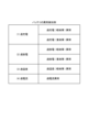
- FIG. 4 is a table showing an example of battery abnormality detection information
- FIG. 1 is a block diagram showing a hybrid system according to an embodiment of the invention.
- FIG. 2 is a table showing an example of battery abnormality detection information.
- a hybrid system 10 according to this embodiment includes an engine 1 , a motor generator 2 , and a battery pack 40 .
- the hybrid system 10 according to this embodiment further includes a DC/DC converter 70 .
- the engine 1 is, for example, a multi-cylinder diesel engine such as a turbocharged, high-output three-cylinder engine or four-cylinder engine. However, the engine 1 is not limited to a diesel engine.
- the engine 1 has an ECU (Engine Control Unit) 150 .
- the ECU 150 of this embodiment is an example of the "first control section" of the present invention.
- ECU 150 controls the operation of engine 1 and controls motor generator 2 and DC/DC converter 70 by communicating with motor generator 2 and DC/DC converter 70 via CAN (Controller Area Network), for example.
- CAN Controller Area Network
- the motor generator 2 operates with electric power supplied from the battery pack 40 to support the engine 1 when power is required, such as when starting or accelerating the industrial machine equipped with the hybrid system 10 .
- the hybrid system 10 is mounted, for example, on industrial machines including construction machines such as forklifts and agricultural machines such as tractors.
- the motor generator 2 uses a regenerative brake or the like to convert kinetic energy of an industrial machine or the like in which the hybrid system 10 is mounted into electric energy to generate electric power.
- the battery pack 40 has a battery 50 , a positive contactor 75 , a negative contactor 76 , a current value detector 65 , and a BMU (Battery Management Unit) 85 .
- Battery 50 is an example of the "secondary battery" of the present invention. Battery 50 is provided as a power source for driving motor generator 2 and supplies electric power to motor generator 2 . Like the hybrid system 10 shown in FIG. 1, the battery 50 may be, for example, a 48V high voltage lithium ion battery (LiB). However, the battery 50 of this embodiment is not limited to a lithium ion battery.
- the battery 50 has a positive (+) terminal 51 and a negative (-) terminal 52 .
- the positive contactor 75 is provided in an electric circuit between the positive terminal 51 of the battery 50 and the motor generator 2 . Specifically, as shown in FIG. 1 , positive contactor 75 is provided on positive wires 173 and 174 that connect positive terminal 51 of battery 50 and motor generator 2 . In other words, the electric circuit between positive terminal 51 of battery 50 and motor generator 2 includes positive wiring 173 and positive wiring 174 .
- the positive contactor 75 is electrically connected to the ECU 150 through a signal line 181 and opens and closes the positive lines 173 and 174 based on a control signal transmitted from the ECU 150 through the signal line 181 .
- the positive contactor 75 may be electrically connected to the BMU 85. In this case, the positive contactor 75 opens and closes the positive wires 173 and 174 based on the control signal transmitted from the BMU 85 . In the description of the present embodiment, the positive contactor 75 is electrically connected to the ECU 150 via the signal line 181 as an example.
- the negative contactor 76 is provided in an electric circuit between the negative terminal 52 of the battery 50 and the motor generator 2 . Specifically, as shown in FIG. 1 , negative contactor 76 is provided on negative wiring 175 that connects negative terminal 52 of battery 50 and motor generator 2 . In other words, the electrical circuit between negative terminal 52 of battery 50 and motor generator 2 includes negative wiring 175 .
- the negative contactor 76 is electrically connected to the BMU 85 through a signal line 182 and opens and closes the negative line 175 based on a control signal transmitted from the BMU 85 through the signal line 182 .
- the negative contactor 76 may be electrically connected to the ECU 150 .
- the negative contactor 76 opens and closes the negative wiring 175 based on the control signal transmitted from the ECU 150 .
- the case where the negative contactor 76 is electrically connected to the BMU 85 via the signal line 182 will be taken as an example.
- the BMU 85 of this embodiment is an example of the "second control unit" of the present invention.
- the BMU 85 is electrically connected to the ECU 150 via a signal line 193 and controls the negative contactor 76 based on a control signal transmitted from the ECU 150 via the signal line 193 .
- the ECU 150 and the BMU 85 communicate with each other by CAN, for example, and monitor each other's states.
- the BMU 85 monitors the state of the battery 50 and can detect an abnormality in the battery 50 . For example, as in the example of abnormality detection shown in FIG. failure) to detect anomalies. Alternatively, the BMU 85 detects an over-discharge (minor failure) abnormality or an over-discharge (major failure) abnormality based on the cell voltage obtained from the CMU. Alternatively, the BMU 85 detects an overtemperature (minor failure) abnormality based on the cell temperature obtained from the CMU. Alternatively, the BMU 85 detects an overcurrent abnormality based on the current value acquired from the current value detection unit 65 provided on the positive electrode wiring 174 .
- the negative wiring 175 electrically connects the negative terminal 52 of the battery 50 and the motor generator 2 and serves as the ground 100B.
- the negative wiring 175 is connected to the body of an industrial machine or the like in which the hybrid system 10 is mounted and grounded.
- Positive wiring 173 electrically connects positive terminal 51 of battery 50 and motor generator 2 and electrically connects motor generator 2 and DC/DC converter 70 .
- battery 50 is a 48V lithium ion battery like hybrid system 10 shown in FIG.
- the DC/DC converter 70 is electrically connected to the battery 80 via positive wiring 171 and negative wiring 172 .
- Examples of the battery 80 include a 12V lead storage battery.
- the negative wiring 172 electrically connects the negative terminal 82 of the battery 80 and the DC/DC converter 70 and serves as the ground 100B.
- the negative wiring 172 is connected and grounded to the body of an industrial machine or the like in which the hybrid system 10 is mounted.
- Positive electrode wiring 171 electrically connects positive electrode terminal 81 of battery 80 and DC/DC converter 70 .
- the battery 80 is a 12V lead-acid battery like the hybrid system 10 shown in FIG. 1, the potential of the positive electrode wiring 171 with respect to the negative electrode wiring 172 is 12V.
- the motor generator 2 uses a regenerative brake or the like to convert the kinetic energy of the industrial machine or the like on which the hybrid system 10 is mounted into electric energy to generate electric power.
- the motor generator 2 supplies voltage to the battery 50 to charge the battery 50 , and supplies voltage to the battery 80 to charge the battery 80 .
- the potential of the positive electrode wiring 173 with respect to the negative electrode wiring 175 is 48V. That is, the generated voltage of the motor generator 2 is 48V.
- the potential of the positive wiring 171 with respect to the negative wiring 172 is 12V. Therefore, the DC/DC converter 70 converts the 48V voltage generated by the motor generator 2 into a 12V voltage. Thereby, the motor generator 2 can supply a voltage of 12 V to the battery 80 via the DC/DC converter 70 to charge the battery 80 .
- DC/DC converter 70 is electrically connected to battery 50 and battery 80, and can charge and discharge between battery 50 and battery 80 based on a control signal transmitted from ECU 150. can.
- the DC/DC converter 70 can discharge the battery 50 and charge the battery 80 by converting the voltage and flowing a constant current (eg, 10 A) from the battery 50 to the battery 80 .
- the DC/DC converter 70 can discharge the battery 80 and charge the battery 50 by converting the voltage and flowing a constant current (eg, 10 A) from the battery 80 to the battery 50 .
- the hybrid system 10 can safely cut off the electric circuit that supplies power from the battery 50 to the motor generator 2 when an abnormality occurs in the battery 50 or when the entire hybrid system 10 is shut down. have a function. Details of this function are described below.
- the ECU 150 when the ignition switch is turned on, the ECU 150 electrically connects the positive wire 174 by transmitting a control signal to the positive contactor 75 through the signal line 181 and executing control to close the positive contactor 75 .
- the BMU 85 electrically connects the negative electrode wiring 175 by executing control to close the negative contactor 76 based on a control signal transmitted from the ECU 150 through the signal line 193 .
- the battery 50 can supply electric power to the motor generator 2 .
- the ECU 150 when the ignition switch is turned off, for example, the ECU 150 transmits a control signal to the positive electrode side contactor 75 through the signal line 181 and executes control to open the positive electrode side contactor 75, thereby electrically disconnecting the positive electrode wiring 174. .
- the BMU 85 electrically cuts off the negative wire 175 by executing control to open the negative contactor 76 based on the control signal transmitted from the ECU 150 through the signal line 193 . As a result, power supply from the battery 50 to the motor generator 2 is stopped.
- the BMU 85 detects, for example, an abnormality in the battery 50 described above with reference to FIG. By executing the control, the positive electrode wiring 174 is electrically cut off.
- the BMU 85 independently transmits the second cutoff signal R2 to the negative contactor 76 via the signal line 182 independently of the control signal transmitted from the ECU 150 to open the negative contactor 76. is electrically cut off.
- the ECU 150 and the BMU 85 communicate with each other and monitor each other's states. Therefore, when the ECU 150 detects an abnormality in the BMU 85 , the positive wire 174 is electrically connected to the positive wire 174 by transmitting the first cutoff signal R 1 to the positive electrode contactor 75 via the signal line 181 and executing control to open the positive electrode contactor 75 . effectively block it. On the other hand, when the BMU 85 detects an abnormality in the ECU 150, the BMU 85 independently transmits the second cutoff signal R2 to the negative contactor 76 via the signal line 182 to shut down the negative contactor 76 without depending on the control signal transmitted from the ECU 150. By executing open control, the negative electrode wiring 175 is electrically cut off.
- the hybrid system 10 according to the present embodiment, two contactors (in this embodiment, the , a positive side contactor 75 and a negative side contactor 76 ) are provided, and the ECU 150 controls the positive side contactor 75 and the BMU 85 controls the negative side contactor 76 . Therefore, even if an abnormality occurs in the battery 50 or in one of the ECU 150 and the BMU 85, the hybrid system 10 according to the present embodiment supplies electric power from the battery 50 to the motor generator 2. can interrupt the electrical circuit that Thereby, the hybrid system 10 according to the present embodiment can improve the safety of the battery 50 that supplies electric power to the motor generator 2 .
- the BMU 85 when the BMU 85 detects, for example, an abnormality in the battery 50 described above with reference to FIG. to run. Therefore, the ECU 150 can more reliably open the positive contactor 75 when an abnormality occurs in the battery 50 , and can more reliably cut off the electric circuit that supplies power from the battery 50 to the motor generator 2 . 2, the BMU 85 independently transmits the second cutoff signal R2 to the negative contactor 76 through the signal line 182 without depending on the control signal transmitted from the ECU 150, and Control to open the contactor 76 is executed.
- the BMU 85 can more reliably open the negative contactor 76 without relying on the ECU 150 when an abnormality occurs in the battery 50, and the electric circuit for supplying power from the battery 50 to the motor generator 2 can be more reliably opened. can be blocked.
- the hybrid system 10 according to the present embodiment can further improve the safety of the battery 50 that supplies electric power to the motor generator 2 .
- the ECU 150 when the ECU 150 detects an abnormality in the BMU 85, the ECU 150 transmits the first cutoff signal R1 to the positive contactor 75 via the signal line 181 to open the positive contactor 75.
- the ECU 150 can more reliably open the positive contactor 75 even when the BMU 85 malfunctions, and can more reliably cut off the electric circuit that supplies power from the battery 50 to the motor generator 2 .
- the BMU 85 detects an abnormality in the ECU 150, the BMU 85 independently transmits a second cutoff signal R2 to the negative contactor 76 via the signal line 182 to open the negative contactor 76 without depending on the control signal transmitted from the ECU 150. do.
- the BMU 85 can more reliably open the negative contactor 76 without relying on the ECU 150 even when an abnormality occurs in the ECU 150, and the electric circuit for supplying power from the battery 50 to the motor generator 2 can be further improved. can be reliably blocked.
- the hybrid system 10 according to the present embodiment can further improve the safety of the battery 50 that supplies electric power to the motor generator 2 .
- the BMU 85 when the BMU 85 detects an abnormality in the battery 50, the BMU 85 independently opens the negative contactor 76 independently of the control signal transmitted from the ECU 150, and the negative terminal 52 of the battery 50 and the motor An electric circuit (in this embodiment, the negative electrode wiring 175) between the generator 2 can be interrupted. Since the BMU 85 can cut off the electric circuit connected to the negative terminal 52 of the battery 50 at an early stage, it is possible to more reliably prevent problems such as a short circuit from occurring in the electric circuit. Thereby, the hybrid system 10 according to the present embodiment can further improve the safety of the battery 50 that supplies electric power to the motor generator 2 .
- the hybrid system 10 according to the present embodiment can be used even when the industrial machine in which the hybrid system 10 is mounted does not have a control unit. Even so, the electric circuit that supplies electric power from the battery 50 to the motor generator 2 can be interrupted using the control unit (that is, the ECU 150 and the BMU 85) provided in the hybrid system 10 itself. As a result, the hybrid system 10 according to the present embodiment can improve the safety of the battery 50 that independently supplies power to the motor generator 2 without depending on the industrial machine or the like in which the hybrid system 10 is mounted.
- the hybrid system 10 can Safety regarding the battery 50 that powers the generator 2 can be improved.
- Engine 2 Motor Generator 10: Hybrid System 40: Battery Pack 50: Battery 51: Positive Terminal 52: Negative Terminal 65: Current Value Detector 70: DC/DC Converter 75: Positive Electrode side contactor 76: negative contactor 80: battery 81: positive terminal 82: negative terminal 85: BMU (battery management unit) 100B: ground 150: ECU (engine control unit) 171: positive wiring 172: Negative wiring 173: Positive wiring 174: Positive wiring 175: Negative wiring 181: Signal line 182: Signal line 193: Signal line
Landscapes
- Engineering & Computer Science (AREA)
- Transportation (AREA)
- Mechanical Engineering (AREA)
- Power Engineering (AREA)
- Chemical & Material Sciences (AREA)
- Combustion & Propulsion (AREA)
- Life Sciences & Earth Sciences (AREA)
- Sustainable Development (AREA)
- Sustainable Energy (AREA)
- Automation & Control Theory (AREA)
- Health & Medical Sciences (AREA)
- Biomedical Technology (AREA)
- General Health & Medical Sciences (AREA)
- Electrochemistry (AREA)
- General Chemical & Material Sciences (AREA)
- Chemical Kinetics & Catalysis (AREA)
- Manufacturing & Machinery (AREA)
- Microelectronics & Electronic Packaging (AREA)
- Electric Propulsion And Braking For Vehicles (AREA)
- Hybrid Electric Vehicles (AREA)
- Charge And Discharge Circuits For Batteries Or The Like (AREA)
- Secondary Cells (AREA)
Abstract
Description
ハイブリッドシステムにおいて、モータジェネレータに電力を供給する二次電池に関する安全性の向上が望まれている。
なお、以下に説明する実施形態は、本発明の好適な具体例であるから、技術的に好ましい種々の限定が付されているが、本発明の範囲は、以下の説明において特に本発明を限定する旨の記載がない限り、これらの態様に限られるものではない。また、各図面中、同様の構成要素には同一の符号を付して詳細な説明は適宜省略する。
図2は、バッテリの異常検知情報の例を示す表である。
本実施形態に係るハイブリッドシステム10は、エンジン1と、モータジェネレータ2と、バッテリパック40と、を備える。本実施形態に係るハイブリッドシステム10は、DC/DCコンバータ70をさらに備える。
Claims (6)
- モータジェネレータと、
前記モータジェネレータの駆動電源として設けられ前記モータジェネレータに電力を供給する二次電池と、
前記二次電池の正極と前記モータジェネレータとの間における電気回路の開閉を行う正極側コンタクタと、
前記二次電池の負極と前記モータジェネレータとの間における電気回路の開閉を行う負極側コンタクタと、
前記正極側コンタクタおよび前記負極側コンタクタのいずれか一方のコンタクタを制御する第1制御部と、
前記第1制御部から送信される制御信号に基づいて前記正極側コンタクタおよび前記負極側コンタクタのいずれか他方のコンタクタを制御する第2制御部と、
を備えたことを特徴とするハイブリッドシステム。 - 前記第1制御部および前記第2制御部は、互いに通信し、
前記第2制御部は、前記二次電池の状態を監視しており、
前記第2制御部が前記二次電池の異常を検出すると、前記第1制御部は、前記一方のコンタクタを開く制御を実行し、前記第2制御部は、前記制御信号に依らず単独で前記他方のコンタクタを開く制御を実行することを特徴とする請求項1に記載のハイブリッドシステム。 - 前記第1制御部および前記第2制御部は、互いに通信し互いの状態を監視しており、
前記第1制御部は、前記第2制御部の異常を検出すると、前記一方のコンタクタを開く制御を実行し、
前記第2制御部は、前記第1制御部の異常を検出すると、前記制御信号に依らず単独で前記他方のコンタクタを開く制御を実行することを特徴とする請求項1または2に記載のハイブリッドシステム。 - 前記一方のコンタクタは、前記正極側コンタクタであり、
前記他方のコンタクタは、前記負極側コンタクタであることを特徴とする請求項1~3のいずれか1項に記載のハイブリッドシステム。 - 前記第1制御部は、エンジンを制御するエンジンコントロールユニットであり、
前記第2制御部は、バッテリパックに内蔵され前記バッテリパックの動作を制御するバッテリマネージメントユニットであることを特徴とする請求項1~4のいずれか1項に記載のハイブリッドシステム。 - 前記二次電池は、リチウムイオン電池であることを特徴とする請求項1~5のいずれか1項に記載のハイブリッドシステム。
Priority Applications (3)
| Application Number | Priority Date | Filing Date | Title |
|---|---|---|---|
| EP22883209.3A EP4420946A4 (en) | 2021-10-20 | 2022-08-29 | Hybrid system |
| US18/702,521 US20240409083A1 (en) | 2021-10-20 | 2022-08-29 | Hybrid system |
| CN202280066345.XA CN118119539A (zh) | 2021-10-20 | 2022-08-29 | 混合动力系统 |
Applications Claiming Priority (2)
| Application Number | Priority Date | Filing Date | Title |
|---|---|---|---|
| JP2021-171889 | 2021-10-20 | ||
| JP2021171889A JP7440728B2 (ja) | 2021-10-20 | 2021-10-20 | ハイブリッドエンジンの制御システム |
Publications (1)
| Publication Number | Publication Date |
|---|---|
| WO2023067897A1 true WO2023067897A1 (ja) | 2023-04-27 |
Family
ID=86059001
Family Applications (1)
| Application Number | Title | Priority Date | Filing Date |
|---|---|---|---|
| PCT/JP2022/032401 Ceased WO2023067897A1 (ja) | 2021-10-20 | 2022-08-29 | ハイブリッドシステム |
Country Status (5)
| Country | Link |
|---|---|
| US (1) | US20240409083A1 (ja) |
| EP (1) | EP4420946A4 (ja) |
| JP (1) | JP7440728B2 (ja) |
| CN (1) | CN118119539A (ja) |
| WO (1) | WO2023067897A1 (ja) |
Cited By (1)
| Publication number | Priority date | Publication date | Assignee | Title |
|---|---|---|---|---|
| US20250214561A1 (en) * | 2023-12-28 | 2025-07-03 | Robert Bosch Gmbh | Controlling high voltage devices |
Families Citing this family (1)
| Publication number | Priority date | Publication date | Assignee | Title |
|---|---|---|---|---|
| CN121014044A (zh) | 2023-04-05 | 2025-11-25 | 软银集团股份有限公司 | 行为控制系统、程序及机器人 |
Citations (5)
| Publication number | Priority date | Publication date | Assignee | Title |
|---|---|---|---|---|
| JP2000156910A (ja) | 1998-11-17 | 2000-06-06 | Fuji Heavy Ind Ltd | ハイブリッド車の制御装置 |
| JP2007255294A (ja) * | 2006-03-23 | 2007-10-04 | Toyota Motor Corp | 車両の電源装置 |
| WO2010109956A1 (ja) * | 2009-03-27 | 2010-09-30 | 株式会社日立製作所 | 蓄電装置 |
| JP2012138278A (ja) * | 2010-12-27 | 2012-07-19 | Toyota Motor Corp | 電源装置の制御装置および電源装置の制御方法 |
| JP2014143863A (ja) * | 2013-01-25 | 2014-08-07 | Fuji Heavy Ind Ltd | 車両用電源装置 |
Family Cites Families (5)
| Publication number | Priority date | Publication date | Assignee | Title |
|---|---|---|---|---|
| WO2011004550A1 (ja) * | 2009-07-10 | 2011-01-13 | パナソニック株式会社 | サイクル数計数回路、電池パック、及び電池システム |
| WO2013015244A1 (ja) * | 2011-07-27 | 2013-01-31 | 三菱電機株式会社 | 二次電池の充電制御装置及び充電制御方法 |
| CN107472032B (zh) * | 2017-08-14 | 2019-12-13 | 中国重汽集团济南动力有限公司 | 一种电动汽车电机控制器高压直流电路控制系统 |
| JP7172499B2 (ja) * | 2018-11-26 | 2022-11-16 | 株式会社デンソー | 電子制御装置 |
| CN109888864B (zh) * | 2019-02-25 | 2021-03-23 | 宁德时代新能源科技股份有限公司 | 电池管理系统 |
-
2021
- 2021-10-20 JP JP2021171889A patent/JP7440728B2/ja active Active
-
2022
- 2022-08-29 WO PCT/JP2022/032401 patent/WO2023067897A1/ja not_active Ceased
- 2022-08-29 EP EP22883209.3A patent/EP4420946A4/en active Pending
- 2022-08-29 CN CN202280066345.XA patent/CN118119539A/zh active Pending
- 2022-08-29 US US18/702,521 patent/US20240409083A1/en active Pending
Patent Citations (5)
| Publication number | Priority date | Publication date | Assignee | Title |
|---|---|---|---|---|
| JP2000156910A (ja) | 1998-11-17 | 2000-06-06 | Fuji Heavy Ind Ltd | ハイブリッド車の制御装置 |
| JP2007255294A (ja) * | 2006-03-23 | 2007-10-04 | Toyota Motor Corp | 車両の電源装置 |
| WO2010109956A1 (ja) * | 2009-03-27 | 2010-09-30 | 株式会社日立製作所 | 蓄電装置 |
| JP2012138278A (ja) * | 2010-12-27 | 2012-07-19 | Toyota Motor Corp | 電源装置の制御装置および電源装置の制御方法 |
| JP2014143863A (ja) * | 2013-01-25 | 2014-08-07 | Fuji Heavy Ind Ltd | 車両用電源装置 |
Non-Patent Citations (1)
| Title |
|---|
| See also references of EP4420946A4 |
Cited By (1)
| Publication number | Priority date | Publication date | Assignee | Title |
|---|---|---|---|---|
| US20250214561A1 (en) * | 2023-12-28 | 2025-07-03 | Robert Bosch Gmbh | Controlling high voltage devices |
Also Published As
| Publication number | Publication date |
|---|---|
| US20240409083A1 (en) | 2024-12-12 |
| JP2023061767A (ja) | 2023-05-02 |
| EP4420946A1 (en) | 2024-08-28 |
| CN118119539A (zh) | 2024-05-31 |
| EP4420946A4 (en) | 2025-10-22 |
| JP7440728B2 (ja) | 2024-02-29 |
Similar Documents
| Publication | Publication Date | Title |
|---|---|---|
| JP6883067B2 (ja) | バッテリー管理システムおよびそのスイッチング方法 | |
| US10195959B2 (en) | Vehicle power control | |
| CN102161315B (zh) | 车辆用电源装置 | |
| JP3568840B2 (ja) | ハイブリッド車両の制御装置 | |
| EP3611045B1 (en) | Electricity storage device controller, electric system, and construction machine | |
| JP5455436B2 (ja) | 電動車両 | |
| US20090039703A1 (en) | Power Supply Device and Control Method of the Power Supply Device | |
| JP6691502B2 (ja) | 車両用電源装置 | |
| JP2001069607A (ja) | ハイブリッド車両の制御装置 | |
| US10513257B2 (en) | Control device for hybrid vehicle | |
| JP6496342B2 (ja) | 車両用制御装置 | |
| CN108656968A (zh) | 车辆用电源装置 | |
| CN106166957A (zh) | 用于在电池断开事件期间激活危险警告灯的车辆系统和方法 | |
| US20240409083A1 (en) | Hybrid system | |
| US10099680B2 (en) | Hybrid vehicle | |
| US11702060B2 (en) | Power relay assembly and vehicle comprising the same and control method of power relay assembly | |
| JP2018198519A (ja) | 車両用電源装置 | |
| JP2018057202A (ja) | 車両用電源装置 | |
| CN113497282A (zh) | 车辆用电池系统 | |
| JP7137341B2 (ja) | 電力制御システム | |
| JP7204509B2 (ja) | 車両 | |
| JP2020125036A (ja) | 電源システム | |
| JP7222737B2 (ja) | 車両 | |
| TWI764517B (zh) | 電動機車的電力系統 | |
| EP3988411A8 (en) | Control device of hybrid vehicle |
Legal Events
| Date | Code | Title | Description |
|---|---|---|---|
| 121 | Ep: the epo has been informed by wipo that ep was designated in this application |
Ref document number: 22883209 Country of ref document: EP Kind code of ref document: A1 |
|
| WWE | Wipo information: entry into national phase |
Ref document number: 202280066345.X Country of ref document: CN |
|
| WWE | Wipo information: entry into national phase |
Ref document number: 18702521 Country of ref document: US |
|
| WWE | Wipo information: entry into national phase |
Ref document number: 2022883209 Country of ref document: EP |
|
| NENP | Non-entry into the national phase |
Ref country code: DE |
|
| ENP | Entry into the national phase |
Ref document number: 2022883209 Country of ref document: EP Effective date: 20240521 |