WO2023067967A1 - 軸封構造、圧縮機および冷凍装置 - Google Patents
軸封構造、圧縮機および冷凍装置 Download PDFInfo
- Publication number
- WO2023067967A1 WO2023067967A1 PCT/JP2022/034828 JP2022034828W WO2023067967A1 WO 2023067967 A1 WO2023067967 A1 WO 2023067967A1 JP 2022034828 W JP2022034828 W JP 2022034828W WO 2023067967 A1 WO2023067967 A1 WO 2023067967A1
- Authority
- WO
- WIPO (PCT)
- Prior art keywords
- compressor
- shaft
- thin plate
- gas
- refrigerant
- Prior art date
- Legal status (The legal status is an assumption and is not a legal conclusion. Google has not performed a legal analysis and makes no representation as to the accuracy of the status listed.)
- Ceased
Links
Images


Classifications
-
- F—MECHANICAL ENGINEERING; LIGHTING; HEATING; WEAPONS; BLASTING
- F04—POSITIVE - DISPLACEMENT MACHINES FOR LIQUIDS; PUMPS FOR LIQUIDS OR ELASTIC FLUIDS
- F04D—NON-POSITIVE-DISPLACEMENT PUMPS
- F04D29/00—Details, component parts, or accessories
- F04D29/05—Shafts or bearings, or assemblies thereof, specially adapted for elastic fluid pumps
- F04D29/056—Bearings
- F04D29/057—Bearings hydrostatic; hydrodynamic
-
- F—MECHANICAL ENGINEERING; LIGHTING; HEATING; WEAPONS; BLASTING
- F04—POSITIVE - DISPLACEMENT MACHINES FOR LIQUIDS; PUMPS FOR LIQUIDS OR ELASTIC FLUIDS
- F04D—NON-POSITIVE-DISPLACEMENT PUMPS
- F04D17/00—Radial-flow pumps, e.g. centrifugal pumps; Helico-centrifugal pumps
- F04D17/08—Centrifugal pumps
- F04D17/10—Centrifugal pumps for compressing or evacuating
-
- F—MECHANICAL ENGINEERING; LIGHTING; HEATING; WEAPONS; BLASTING
- F04—POSITIVE - DISPLACEMENT MACHINES FOR LIQUIDS; PUMPS FOR LIQUIDS OR ELASTIC FLUIDS
- F04D—NON-POSITIVE-DISPLACEMENT PUMPS
- F04D25/00—Pumping installations or systems
- F04D25/02—Units comprising pumps and their driving means
- F04D25/06—Units comprising pumps and their driving means the pump being electrically driven
-
- F—MECHANICAL ENGINEERING; LIGHTING; HEATING; WEAPONS; BLASTING
- F04—POSITIVE - DISPLACEMENT MACHINES FOR LIQUIDS; PUMPS FOR LIQUIDS OR ELASTIC FLUIDS
- F04D—NON-POSITIVE-DISPLACEMENT PUMPS
- F04D29/00—Details, component parts, or accessories
- F04D29/05—Shafts or bearings, or assemblies thereof, specially adapted for elastic fluid pumps
- F04D29/056—Bearings
-
- F—MECHANICAL ENGINEERING; LIGHTING; HEATING; WEAPONS; BLASTING
- F04—POSITIVE - DISPLACEMENT MACHINES FOR LIQUIDS; PUMPS FOR LIQUIDS OR ELASTIC FLUIDS
- F04D—NON-POSITIVE-DISPLACEMENT PUMPS
- F04D29/00—Details, component parts, or accessories
- F04D29/08—Sealings
- F04D29/10—Shaft sealings
- F04D29/102—Shaft sealings especially adapted for elastic fluid pumps
-
- F—MECHANICAL ENGINEERING; LIGHTING; HEATING; WEAPONS; BLASTING
- F16—ENGINEERING ELEMENTS AND UNITS; GENERAL MEASURES FOR PRODUCING AND MAINTAINING EFFECTIVE FUNCTIONING OF MACHINES OR INSTALLATIONS; THERMAL INSULATION IN GENERAL
- F16J—PISTONS; CYLINDERS; SEALINGS
- F16J15/00—Sealings
- F16J15/16—Sealings between relatively-moving surfaces
- F16J15/164—Sealings between relatively-moving surfaces the sealing action depending on movements; pressure difference, temperature or presence of leaking fluid
-
- F—MECHANICAL ENGINEERING; LIGHTING; HEATING; WEAPONS; BLASTING
- F16—ENGINEERING ELEMENTS AND UNITS; GENERAL MEASURES FOR PRODUCING AND MAINTAINING EFFECTIVE FUNCTIONING OF MACHINES OR INSTALLATIONS; THERMAL INSULATION IN GENERAL
- F16J—PISTONS; CYLINDERS; SEALINGS
- F16J15/00—Sealings
- F16J15/16—Sealings between relatively-moving surfaces
- F16J15/40—Sealings between relatively-moving surfaces by means of fluid
- F16J15/406—Sealings between relatively-moving surfaces by means of fluid by at least one pump
-
- F—MECHANICAL ENGINEERING; LIGHTING; HEATING; WEAPONS; BLASTING
- F16—ENGINEERING ELEMENTS AND UNITS; GENERAL MEASURES FOR PRODUCING AND MAINTAINING EFFECTIVE FUNCTIONING OF MACHINES OR INSTALLATIONS; THERMAL INSULATION IN GENERAL
- F16J—PISTONS; CYLINDERS; SEALINGS
- F16J15/00—Sealings
- F16J15/44—Free-space packings
-
- F—MECHANICAL ENGINEERING; LIGHTING; HEATING; WEAPONS; BLASTING
- F25—REFRIGERATION OR COOLING; COMBINED HEATING AND REFRIGERATION SYSTEMS; HEAT PUMP SYSTEMS; MANUFACTURE OR STORAGE OF ICE; LIQUEFACTION SOLIDIFICATION OF GASES
- F25B—REFRIGERATION MACHINES, PLANTS OR SYSTEMS; COMBINED HEATING AND REFRIGERATION SYSTEMS; HEAT PUMP SYSTEMS
- F25B31/00—Compressor arrangements
- F25B31/02—Compressor arrangements of motor-compressor units
- F25B31/026—Compressor arrangements of motor-compressor units with compressor of rotary type
Definitions
- the present disclosure relates to a shaft seal structure, a compressor and a refrigeration system.
- a shaft seal structure is provided around the drive shaft of the electric motor to separate the pressure difference between the high-pressure portion that is pressurized by the operation of the compression mechanism and other portions.
- a labyrinth seal is employed as the shaft sealing structure (see, for example, Patent Document 1).
- a labyrinth seal is formed by a ring-shaped metallic sealing member.
- a plurality of protrusions (fins) are provided on the inner peripheral surface of the seal member at intervals in the direction along the drive shaft. A predetermined gap is set between each projection and the outer peripheral surface of the drive shaft.
- a force in the radial direction acts on the drive shaft under transient conditions, and the drive shaft may be displaced in the radial direction.
- thermal expansion also occurs in the shaft seal structure.
- a labyrinth seal is employed as a shaft sealing structure, it is necessary to maintain the distance between each protrusion of the seal member and the drive shaft so that the protrusions of the seal member forming the labyrinth seal and the drive shaft do not interfere with each other. It is necessary to set the gap relatively large. Therefore, a relatively large amount of gas leaks from the high pressure side of the centrifugal compressor to the low pressure side through the clearance of the labyrinth seal.
- An object of the present disclosure is to reduce the amount of fluid leakage in the shaft seal structure.
- a first aspect of the present disclosure is directed to a shaft sealing structure (90).
- a shaft sealing structure (90) according to a first aspect includes a housing (91) having an insertion hole (92) through which a rotating shaft (41) is inserted, and a flexible housing (91) accommodated in the insertion hole (92). and a support (97) disposed between the housing (91) and the thin plate (93) to elastically support the thin plate (93).
- the inner peripheral surface of the thin plate (93) faces the rotating shaft (41) and forms a gap (G2) with the rotating shaft (41).
- the support (97) suppresses fluid flow in the direction along the rotation shaft (41).
- the cylindrical thin plate (93) is elastically supported on the outer peripheral side by the support (97) within the insertion hole (92) of the housing (91).
- the thin plate (93) is adaptively flexed.
- the bent thin plate (93) is restored by the support of the support (97) when the rotating shaft (41) returns to its position.
- a gap (G2) is secured between the rotating shaft (41) and the thin plate (93). Therefore, the width (d2) of the gap (G2) between the rotating shaft (41) and the thin plate (93) can be reduced.
- the support (97) restricts fluid flow in the direction along the rotation axis (41) between the housing (91) and the thin plate (93). Therefore, the amount of fluid leakage in the shaft sealing structure (90) can be reduced.
- a second aspect of the present disclosure is the shaft sealing structure (90) of the first aspect, wherein the support (97) is composed of a mesh member (110).
- the support (97) is composed of the mesh member (110).
- the amount of fluid leakage in the shaft sealing structure (90) can be adjusted according to the density of the wire rods forming the mesh member (110).
- a third aspect of the present disclosure is the shaft sealing structure (90) of the first aspect, wherein the support (97) is cylindrical with a plurality of spring elements (101) for receiving the thin plate (93).
- the support (97) is composed of the elastic member (100) and the filler (105).
- the thin plate (93) is elastically supported by a plurality of spring elements (101) provided on the elastic member (100).
- a filler (105) is filled between the elastic member (100) and the housing (91) and between the elastic member (100) and the thin plate (93) to prevent fluid from flowing through the gaps between them. can be inhibited.
- the filler (105) since the filler (105) is flexible, it deforms according to the bending of the thin plate (93). Therefore, when the rotary shaft (91) is displaced in the radial direction, the thin plate (93) is bent to follow the displacement of the rotary shaft (91), and the gap between the rotary shaft (91) and the thin plate (93) is formed. (G2) can be secured with good responsiveness.
- a fourth aspect of the present disclosure is the shaft sealing structure (90) of the first aspect, wherein the support (97) comprises a mesh member (110) and a flexible structure filled in the voids of the mesh member (110).
- a shaft sealing structure (90) composed of a filler material (115) having a
- the support (97) is composed of the mesh member (110) and the filler (115).
- the gaps of the mesh member (110) are filled with the filler (115), so that the flow of fluid through the gaps of the mesh member (110) can be blocked.
- the filler (115) since the filler (115) is flexible, it deforms according to the bending of the thin plate (93). Therefore, when the rotating shaft (41) is displaced in the radial direction, the thin plate (93) is made to bend following the displacement of the rotating shaft (41), and the gap between the rotating shaft (41) and the thin plate (93) is formed. (G2) can be secured with good responsiveness.
- a fifth aspect of the present disclosure is directed to a compressor (2).
- a compressor (2) according to a fifth aspect comprises a shaft sealing structure (90) according to any one of the first to fourth aspects, and the rotary shaft (41) sealed by the shaft sealing structure (90). ), a compression mechanism (50) for compressing fluid sucked by driving the electric motor (40), and the shaft seal structure (90) interposed between the compression mechanism (50) and the A bearing (60) is provided at a position on the rotor (42) side of the electric motor (40) and rotatably supports the rotating shaft (41) on its outer periphery.
- the shaft seal structure (90) described above is arranged between the compression mechanism (50) and the bearing (60).
- the side on which the compression mechanism (50) is provided is relatively high pressure side
- the rotor (42) side of the electric motor (40) is relatively low pressure side.
- the amount of fluid leakage from the high pressure side to the low pressure side of the compressor (2) is reduced by the shaft seal structure (90). This can suppress an increase in pressure in the space where the rotor (42) is arranged. Thereby, the stirring loss (windage loss) in the electric motor (40) can be reduced, and the performance of the compressor (2) can be improved.
- a sixth aspect of the present disclosure is the compressor (2) of the fifth aspect, in which a gas flow path (120) for supplying cooling gas to the bearing (60) is provided.
- cooling gas is supplied to the bearing (60) through the gas flow path (120).
- the bearing (60) is cooled by cooling gas supplied through the gas flow path (120).
- seizing of the bearing (60) can be suppressed.
- a seventh aspect of the present disclosure is the compressor (2) of the fifth or sixth aspect, wherein the bearing (60) is a foil gas bearing (80).
- the foil gas bearing (80) includes a flexible top foil (83), a gap (G1) is formed between the top foil (83) and the rotating shaft (41), and the gap ( The rotating shaft (41) is supported by the gas film (89) generated in G1).
- a foil gas bearing (80) is employed as the bearing (60) that supports the rotating shaft (41) on its outer periphery.
- the top foil (83) constitutes a bearing surface (84) and supports the load while allowing the bearing surface (84) to flex.
- gas is drawn into the gap (G1) between the top foil (83) and the rotating shaft (41) to form a gas film (89).
- This gas film (89) lifts the rotating shaft (41) from the bearing surface (84) of the top foil (83).
- the bearing (60) rotatably supports the rotating shaft (41) without contact.
- Such a foil gas bearing (80) is advantageous in reducing the amount of frictional heat and wear of the bearing surface (84) generated in the bearing surface (84) due to the rotation of the rotary shaft (41). It is suitable as a bearing (60) for supporting the rotating shaft (41) of (40).
- An eighth aspect of the present disclosure is the compressor (2) according to the seventh aspect, wherein the gap (G2) between the thin plate (93) of the shaft sealing structure (90) and the rotating shaft (41) is The width (d2) of the compressor (2) is set wider than the width (d1) of the gap (G1) between the top foil (83) of the bearing (60) and the rotating shaft (41). is.
- the width (d2) of the gap (G2) between the thin plate (93) of the shaft sealing structure (90) and the rotating shaft (41) is equal to the width (d2) of the top foil (83) of the bearing (80) and the rotating shaft (41). It is set wider than the width (d1) of the gap (G1) between (41). This reduces the amount of heat generated by the rotation of the rotating shaft (41) in the shaft sealing structure (90). As a result, seizure of the shaft sealing structure (90) can be suppressed.
- the dynamic pressure grooves (140) are formed in the outer peripheral surface facing the thin plate (93) of the rotating shaft (41).
- gas flows through the dynamic pressure grooves (140) from the rotor (42) side to the compression mechanism (50) side so as to generate dynamic pressure.
- gas can be pushed back from the low-pressure side of the compressor (2) to the high-pressure side in accordance with the rotation of the rotating shaft (41). This is advantageous in reducing the amount of gas leaked from the shaft seal structure (90) provided in the compressor (2).
- a tenth aspect of the present disclosure is the compressor (2) according to any one of the fifth to ninth aspects, wherein the inner peripheral surface of the thin plate (93) is provided with the above-described
- the compressor (2) is provided with dynamic pressure grooves (140a, 140b) that generate dynamic pressure when gas flows from the rotor (42) side to the compression mechanism (50) side.
- the dynamic pressure grooves (140) are formed in the inner peripheral surface of the thin plate (93).
- gas flows through the dynamic pressure grooves (140) from the rotor (42) side to the compression mechanism (50) side so as to generate dynamic pressure.
- gas can be pushed back from the low-pressure side of the compressor (2) to the high-pressure side in accordance with the rotation of the rotating shaft (41). This is advantageous in reducing the amount of gas leaked from the shaft seal structure (90) provided in the compressor (2).
- An eleventh aspect of the present disclosure is the compressor (2) according to any one of the fifth to tenth aspects, wherein the thin plate (93) and the support (97) are in contact with each other over the entire circumference. machine (2).
- the thin plate (93) and the support (97) are in contact with each other over the entire circumference.
- the flow path for the fluid to flow in the direction along the rotating shaft (41) can be closed. This is advantageous in reducing the amount of fluid leakage in the shaft seal structure (90).
- a twelfth aspect of the present disclosure is the compressor (2) according to any one of the fifth to eleventh aspects, which constitutes the centrifugal compressor (2).
- the compressor (2) is a centrifugal compressor (2).
- the compression mechanism (50) includes impellers (51, 52).
- the impeller chambers (23, 24) in which the impellers (51, 52) of the centrifugal compressor (2) are housed are pressurized by the rotation of the impellers (51, 52) to a relatively high pressure. Therefore, a seal is required to separate the pressure difference between the motor chamber (26) in which the motor (40) is housed and the impeller chambers (23, 24). As such a seal, the shaft seal structure (90) described above can be effectively used.
- a thirteenth aspect of the present disclosure is the compressor (2) according to any one of the fifth to twelfth aspects, wherein the gas is an HFC refrigerant, an HFO refrigerant, a mixed refrigerant of an HFC refrigerant and an HFO refrigerant, a CF3I refrigerant , a carbon dioxide refrigerant, and a hydrocarbon refrigerant.
- the gas compressed by the compressor (2) is refrigerant such as HFC refrigerant.
- refrigerant such as HFC refrigerant.
- the above-described shaft seal structure (90) can also be effectively used in the compressor (2) that compresses such a refrigerant.
- a fourteenth aspect of the present disclosure is directed to a refrigeration system (1).
- a refrigeration system (1) according to a fourteenth aspect comprises a compressor (2) according to any one of the fifth to thirteenth aspects.
- the compressor (2) constitutes a refrigerant circuit (10) that circulates refrigerant to perform a refrigeration cycle.
- the compressor (2) described above is used in the refrigerant circuit (10). This contributes to higher efficiency of the refrigeration cycle performed in the refrigeration system (1).
- FIG. 1 is a schematic configuration diagram of a refrigerant circuit provided in a refrigerating apparatus of Embodiment 1.
- FIG. 2 is a longitudinal sectional view illustrating a schematic configuration of the compressor of Embodiment 1.
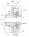
- FIG. 3 is a vertical cross-sectional view illustrating a main part of the compressor of Embodiment 1.
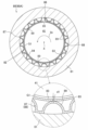
- FIG. 4 is a cross-sectional view illustrating a schematic configuration of the radial bearing along line IV-IV in FIG. 3.
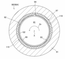
- FIG. 5 is a cross-sectional view illustrating a schematic configuration of the shaft sealing structure taken along line VV in FIG.
- FIG. 6 is a cross-sectional view of the portion corresponding to FIG. 5 illustrating the shaft sealing structure of the second embodiment.
- FIG. 7 is a cross-sectional view of a portion corresponding to FIG. 5 illustrating the shaft sealing structure of Embodiment 3.
- FIG. FIG. 8 is a cross-sectional view of a main part illustrating dynamic pressure grooves formed on the outer peripheral surface of the drive shaft of the centrifugal compressor of the first modified example.
- FIG. 9 is a cross-sectional view of a main part illustrating dynamic pressure grooves formed in the inner peripheral surface of a thin plate included in the shaft sealing structure of the second modified example.
- FIG. 10 is a vertical cross-sectional view illustrating a schematic configuration of a compressor of a third modified example.
- a compressor (2) of the present disclosure is provided in a refrigeration system (1).
- a refrigeration system (1) has a refrigerant circuit (10).
- the refrigerant circuit (10) is filled with refrigerant.
- the fluid compressed by the compressor (2) of this example is refrigerant.
- the refrigerant is any one of HFC (Hydro Fluoro Carbon) refrigerant, HFO (Hydro Fluoro Olefin) refrigerant, mixed refrigerant of HFC refrigerant and HFO refrigerant, CF3I (Trifluoroiodomethane) refrigerant, carbon dioxide refrigerant, and hydrocarbon refrigerant is one.
- the refrigerant circuit (10) includes a main circuit (11), a sub circuit (12), a branch circuit (13) and a return circuit (14).
- the main circuit (11) includes a main pipe (11a), a compressor (2), a radiator (condenser) (3), a first pressure reducing mechanism (4), and an evaporator (5).
- the compressor (2), radiator (3), first pressure reducing mechanism (4) and evaporator (5) are connected in series by a main pipe (11a).
- the first pressure reducing mechanism (4) is, for example, an expansion valve.
- the main circuit (11) circulates refrigerant to perform a vapor compression refrigeration cycle.
- the gas refrigerant compressed by the compressor (2) releases heat to the air in the radiator (3).
- the gas refrigerant is liquefied and changed to a liquid refrigerant.
- the liquid refrigerant that has released heat is decompressed by the first decompression mechanism (4).
- the decompressed liquid refrigerant evaporates in the evaporator (5).
- the liquid refrigerant evaporates and changes to gas refrigerant.
- the evaporated gaseous refrigerant is sucked into the compressor (2).
- the compressor (2) compresses the sucked gas refrigerant.
- the compressor (2) in this example is a two-stage centrifugal compressor (2).
- the compressor (2) has a high pressure impeller chamber (23) and a low pressure impeller chamber (24) (see FIG. 2).
- the high pressure impeller chamber (23) constitutes a high pressure side compression chamber.
- the low-pressure impeller chamber (24) constitutes a low-pressure side compression chamber.
- the compressor (2) compresses the refrigerant in two stages in the high pressure impeller chamber (23) and the low pressure impeller chamber (24).
- the sub-circuit (12) has a sub-pipe (12a).
- One end of the secondary pipe (12a) is connected to the high pressure impeller chamber (23) of the compressor (2).
- the other end of the secondary pipe (12a) is connected to the low pressure impeller chamber (24) of the compressor (2).
- the secondary pipe (12a) connects the discharge side of the low pressure impeller chamber (24) and the suction side of the high pressure impeller chamber (23). Refrigerant compressed in the low-pressure impeller chamber (24) is sucked into the high-pressure impeller chamber (23) through the secondary pipe (12a).
- the branch circuit (13) has a branch pipe (13a), a second pressure reducing mechanism (6), and a heater (7).
- the branch pipe (13a) branches into two on the way.
- the branch pipe (13a) includes a main branch pipe (13b), a first branch pipe (13c), and a second branch pipe (13d).
- the main branch pipe (13b) is a pipe forming a common part of the branch pipe (13a), and constitutes one end of the branch pipe (13a).
- One end of the branch pipe (13a) is connected between the radiator (3) and the first pressure reducing mechanism (4) in the main pipe (11a).
- the first branch pipe (13c) and the second branch pipe (13d) are pipes branched from the main branch pipe (13b), and constitute the other end of the branch pipe (13a).
- the other end of the branch pipe (13a) formed by the first branch pipe (13c) is connected to the inlet of the first cooling gas flow path (120A) provided in the compressor (2).
- the other end of the branch pipe (13a) formed by the second branch pipe (13d) is connected to the inlet of the second cooling gas flow path (120B) provided in the compressor (2).
- the second decompression mechanism (6) is provided in the main branch pipe (13b).
- the second pressure reducing mechanism (6) is, for example, an expansion valve.
- the heater (7) is provided in the main branch pipe (13b) on the branch side of the branch pipe (13a) relative to the second pressure reducing mechanism (6).
- the second decompression mechanism (6) and the heater (7) are connected in series by a main branch pipe (13b).
- the liquid refrigerant flowing through the main branch pipe (13b) is decompressed by the second decompression mechanism (6).
- the decompressed liquid refrigerant is heated in the heater (7).
- the liquid refrigerant evaporates and changes to gas refrigerant.
- This gas refrigerant is introduced into the first gas flow path (120A) through the first branch pipe (13c), and is introduced into the second gas flow path (120B) through the second branch pipe (13d).
- the return circuit (14) has a return pipe (14a).
- the return pipe (14a) branches into two on the way. Specifically, it includes a main return pipe (14b), a first return pipe (14c), and a second return pipe (14d).
- the main return pipe (14b) is a pipe forming a common portion of the return pipe (14a), and constitutes one end of the return pipe (14a).
- One end of this return pipe (14a) is connected between the evaporator (5) and the compressor (2) in the main pipe (11a).
- the first return pipe (14c) and the second return pipe (14d) are pipes branched from the main return pipe (14b), respectively, and constitute the other end of the return pipe (14a).
- the other end of the return pipe (14a) formed by the first return pipe (14c) is connected to the discharge port of the first gas flow path (120A) provided in the compressor (2).
- the other end of the return pipe (14a) formed by the second return pipe (14d) is connected to the outlet of the second gas flow path (120B) provided in the compressor (2).
- the refrigerating device (1) of this embodiment is, for example, an air conditioner.
- the air conditioner may be a combined cooling and heating machine that switches between cooling and heating.
- the refrigerant circuit (10) has a switching mechanism for switching the circulation direction of the refrigerant.
- the switching mechanism is, for example, a four-way switching valve.
- the air conditioner may be a cooling-only machine or a heating-only machine.
- the refrigerating device (1) may be a water heater, a chiller unit, a cooling device for cooling the air inside the refrigerator, or the like.
- a cooling device is a device that cools the air inside a refrigerator, freezer, container, or the like.
- the compressor (2) constitutes the refrigerant circuit (10).
- the compressor (2) draws in low-pressure gas refrigerant and compresses the gas refrigerant.
- the compressor (2) discharges the high-pressure gas refrigerant after compression.
- the direction along the drive shaft (41) of the compressor (2) will be referred to as the "axial direction”
- the direction perpendicular to the axial direction will be referred to as the "radial direction”.
- a direction along the circumference is called a “circumferential direction”.
- the compressor (2) includes a casing (20), an electric motor (40), a compression mechanism (50), bearings (60), and a shaft seal structure (90).
- the casing (20) is a generally cylindrical closed container with both ends closed.
- the casing (20) is installed in a posture such that its center line is substantially horizontal.
- the casing (20) extends axially and has an interior space (S).
- the internal space (S) of the casing (20) is defined on one side in the axial direction by the first wall (21) and on the other side in the axial direction by the second wall (22).
- the space on one side partitioned outward in the axial direction by the first wall (21) constitutes the high-pressure impeller chamber (23).
- the space on the other side defined axially outward by the second wall (22) constitutes a low-pressure impeller chamber (24).
- a compression space (25) is formed in each of the outer periphery of the high-pressure impeller chamber (23) and the outer periphery of the low-pressure impeller chamber (24).
- an intermediate space partitioned axially inward by the first wall (21) and the second wall (22) forms a motor room (26).
- the motor room (26) is located between the high pressure impeller room (23) and the low pressure impeller room (24).
- a pressure difference is generated among the high-pressure impeller chamber (23), the low-pressure impeller chamber (24), and the motor chamber (26).
- the casing (20) is provided with a first suction flow path (27), a first discharge flow path (28), a second suction flow path (29), and a second discharge flow path (30).
- the casing (20) is further provided with a cooling gas flow path (120) for supplying cooling gas to the bearing (60).
- the cooling gas in this example is gas refrigerant supplied to the compressor (2) through the branch circuit (13).
- the cooling gas flow path (120) will be described later.
- the first intake channel (27) and the first discharge channel (28) are formed at one end of the casing (20).
- One end of the first suction flow path (27) is connected to the secondary pipe (12a).
- the other end of the first suction flow path (27) opens into the central portion of the high pressure impeller chamber (23).
- One end of the first discharge flow path (28) is connected to the compression space (25) of the high pressure impeller chamber (23).
- the other end of the first discharge channel (28) is connected to the main pipe (11a).
- the second intake channel (29) and the second discharge channel (30) are formed at the other end of the casing (20).
- One end of the second suction flow path (29) is connected to the main pipe (11a).
- the other end of the second suction flow path (29) opens into the central portion of the low-pressure impeller chamber (24).
- One end of the second discharge flow path (30) is connected to the compression space (25) of the low pressure impeller chamber (24).
- the other end of the second discharge channel (30) is connected to the sub-pipe (12a).
- the electric motor (40) is a drive source for the compression mechanism (50).
- the electric motor (40) is housed in the electric motor room (26).
- the electric motor (40) is, for example, a permanent magnet synchronous motor (PMSM).
- the electric motor (40) has a drive shaft (41), a rotor (42) and a stator (43).
- the electric motor (40) is provided in a posture in which the direction (axial direction) of the axis (X) of the drive shaft (41) is horizontal.
- the drive shaft (41) is an example of a rotating shaft.
- the drive shaft (41) extends through the internal space (S) in a direction along the central axis of the casing (20).
- the drive shaft (41) is inserted through insertion holes (31) respectively formed in the first wall (21) and the second wall (22).
- One end of the drive shaft (41) is located in the high pressure impeller chamber (23).
- the other end of the drive shaft (41) is located in the low pressure impeller chamber (24).
- the drive shaft (41) is a rod-shaped member for driving the compression mechanism (50).
- the drive shaft (41) is sealed by a shaft sealing structure (90).
- the rotor (42) is generally cylindrical.
- the drive shaft (41) is inserted through the rotor (42).
- the rotor (42) is fixed to the drive shaft (41).
- the rotor (42) is arranged substantially coaxial with the drive shaft (41).
- the rotor (42) is provided with a plurality of permanent magnets. The rotor (42) rotates together with the drive shaft (41).
- the stator (43) is generally cylindrical.
- the stator (43) is arranged to surround the rotor (42).
- the stator (43) is fixed to the inner wall of the casing (20).
- the stator (43) is made of a magnetic material such as by stacking steel plates.
- a coil is wound around the stator (43).
- the inner peripheral surface of the stator (43) faces the outer peripheral surface of the rotor (42) with a predetermined gap (air gap) in the radial direction.
- the electric motor (40) rotates the drive shaft (41) due to the interaction of magnetic flux and current between the rotor (42) and the stator (43).
- the rotor (42) and the stator (43) partition the motor room (26) into a first space (S1) and a second space (S2).
- the first space (S1) is a space on the high pressure impeller chamber (23) side.
- the second space (S2) is a space on the low pressure impeller chamber (24) side.
- a thrust plate (44) is provided on the drive shaft (41) of this example.
- the thrust plate (44) is located near the high-pressure impeller chamber (23) in the first space (S1).
- the thrust plate (44) is formed in an annular shape extending radially outward from the main body (41a) of the drive shaft (41).
- the thrust plate (44) is configured as a component separate from the main body (41a) of the drive shaft (41).
- the thrust plate (44) may be configured integrally with the body (41a) of the drive shaft (41).
- the compression mechanism (50) compresses the sucked gas refrigerant by being driven by the electric motor (40).
- the compression mechanism (50) has a high pressure impeller (51) and a low pressure impeller (52).
- the high pressure impeller (51) is housed in the high pressure impeller chamber (23).
- the high pressure impeller (51) is fixed to one end of the drive shaft (41).
- the low pressure impeller (52) is housed in the low pressure impeller chamber (24).
- the low pressure impeller (52) is fixed to the other end of the drive shaft (41).
- the high pressure impeller (51) and the low pressure impeller (52) each have a plurality of blades and are generally conical.
- the high pressure impeller (51) and the low pressure impeller (52) rotate integrally with the drive shaft (41).
- the high pressure impeller (51) rotates, the gas refrigerant sucked into the high pressure impeller chamber (23) is compressed in the compression space (25) by centrifugal force.
- the low-pressure impeller (52) rotates, gas refrigerant drawn into the low-pressure impeller chamber (24) is compressed in the compression space (25) by centrifugal force.
- the high pressure impeller chamber (23) is pressurized by the rotation of the high pressure impeller (51). As a result, the air pressure in the high pressure impeller chamber (23) becomes relatively high. At this time, the air pressure in the motor room (26) becomes relatively low.
- the low pressure impeller chamber (24) is pressurized by the rotation of the low pressure impeller (52). As a result, the air pressure in the low-pressure impeller chamber (24) becomes an intermediate pressure higher than that of the electric motor chamber (26) and lower than that of the high-pressure impeller chamber (23).
- the compressor (2) includes, as bearings (60), a thrust bearing (70), a first radial bearing (80A), and a second radial bearing (80B).
- the thrust bearing (70) and the first radial bearing (80A) are held by the first holding member (61).
- the first holding member (61) is arranged in the first space (S1).
- the second radial bearing (80B) is held by the second holding member (66).
- the second holding member (66) is arranged in the second space (S2).
- the first holding member (61) is generally formed in a disc shape.
- the outer peripheral surface of the first holding member (61) is fixed to the inner wall of the casing (20).
- An insertion hole (62) is formed in the central portion of the first holding member (61).
- the drive shaft (41) is inserted through the insertion hole (62).
- a tubular portion (63) is provided around the insertion hole (62) of the first holding member (61).
- the tubular portion (63) is positioned on the rotor (42) side of the first holding member (61).
- the first holding member (61) partitions the first space (S1) into two spaces in the axial direction.
- One space constitutes a first upstream flow path (122a).
- the other space forms a first downstream flow path (123a).
- the first upstream flow path (122a) is located on the high pressure impeller chamber (23) side with respect to the first holding member (61).
- the first downstream flow path (123a) is located on the rotor (42) side with respect to the first holding member (61).
- the second holding member (66) is generally formed in a disc shape.
- the outer peripheral surface of the second holding member (66) is fixed to the inner wall of the casing (20).
- An insertion hole (67) is formed in the central portion of the second holding member (66).
- the drive shaft (41) is inserted through the insertion hole (67).
- a tubular portion (68) is provided around the insertion hole (67) of the second holding member (66).
- the cylindrical portion (68) is positioned on the rotor (42) side of the second holding member (66).
- the second holding member (66) partitions the second space (S2) into two spaces in the axial direction.
- One space constitutes a second upstream flow path (122b).
- the other space forms a second downstream flow path (123b).
- the second upstream flow path (122b) is located on the low-pressure impeller chamber (24) side with respect to the second holding member (66).
- the second downstream flow path (123b) is located on the rotor (42) side with respect to the second holding member (66).
- a first accommodating portion (64) is formed in the end face of the first holding member (61) on the high-pressure impeller chamber (23) side.
- the first accommodation portion (64) is a recess that is annularly recessed around the opening of the insertion hole (62) of the first holding member (61).
- a thrust plate (44) is positioned in the first accommodation portion (64). The thrust bearing (70) is fitted into the first accommodating portion (64) in relation to the thrust plate (44) and fixed to the first holding member (61).
- a second accommodation portion (65) is formed on the inner peripheral surface of the insertion hole (62) of the first holding member (61).
- the second accommodation portion (65) is a recess that is cylindrically recessed radially outward.
- the second accommodation portion (65) is positioned closer to the rotor (42) than the first accommodation portion (64).
- the first radial bearing (80A) is fitted into the second accommodation portion (65).
- the first radial bearing (80A) is fixed to the first holding member (61) within the second accommodation portion (65).
- the first radial bearing (80A) and the thrust bearing (70) are each arranged around the drive shaft (41) in the first space (S1). Both the first radial bearing (80A) and the thrust bearing (70) are connected to the rotor (42) side through the first shaft seal structure (90A) between the compression mechanism (50) (high pressure impeller (51)) and the rotor (42). position.
- the first radial bearing (80A) and the thrust bearing (70) each rotatably support the drive shaft (41) on its outer periphery.
- a third accommodating portion (69) is formed on the inner peripheral surface of the insertion hole (67) of the second holding member (66).
- the third accommodation portion (69) is a recess that is cylindrically recessed toward the radially outer side.
- the second radial bearing (80B) is fitted into the third accommodation portion (69).
- the second radial bearing (80B) is fixed to the second holding member (66) within the third accommodation portion (69).
- the second radial bearing (80B) is arranged around the drive shaft (41) in the second space (S2).
- the second radial bearing (80B) is provided on the rotor (42) side via the second shaft seal structure (90B) between the compression mechanism (50) (low-pressure impeller (52)) and the second radial bearing (80B).
- the second radial bearing (80B) rotatably supports the drive shaft (41) on its outer periphery.
- the thrust bearing (70) of this example is a foil gas bearing. As shown in FIG. 3, the thrust bearing (70) includes a first base member (71), a first back foil (72), a first top foil (73), a spacer (74) and a second top foil (74). It comprises a foil (75), a second back foil (76) and a second base member (77). The first base member (71) and the second base member (77) are combined together to form a bearing housing (78).
- the bearing housing (78) accommodates the first back foil (72), the first top foil (73), the spacer (74), the second top foil (75) and the second back foil (76).
- the first top foil (73) and the second top foil (75) are arranged on both sides of the thrust plate (44) in the axial direction.
- the first back foil (72) is arranged between the first top foil (73) and the first base member (71).
- a second back foil (76) is positioned between the second top foil (75) and the second base member (77).
- the spacer (74) is formed in an annular shape.
- the spacer (74) is arranged on the outer peripheral side of the thrust plate (44).
- a spacer (74) is sandwiched between the first top foil (73) and the second top foil (75).
- a spacer (74) secures a gap between the first top foil (73) and the second top foil (75).
- the first top foil (73) and the second top foil (75) are each formed in an annular shape. Both the first top foil (73) and the second top foil (75) are made of thin metal plates and have flexibility.
- the first back foil (72) and the second back foil (76) are each formed in an annular shape.
- the first back foil (72) elastically supports the first top foil (73).
- the second back foil (76) elastically supports the second top foil (75).
- Both the first back foil (72) and the second back foil (76) are for example bump foils.
- Bump foils consist of thin metal sheets corrugated to form flexible spring elements.
- a predetermined gap is set between the first top foil (73) and the thrust plate (44) and between the second top foil (75) and the thrust plate (44).
- the first top foil (73) and the second top foil (75) form gaps with the rotating shaft (41), respectively, and the gas flows through the first top foil (73) and the second top foil (75). It is drawn into the gap between the second top foil (75) and the thrust plate (44) creating a gas film.
- the gas film lifts the drive shaft (41) from the first top foil (73) and the second top foil (75).
- the thrust bearing (70) supports the drive shaft (41) without contact with the gas film.
- Both the first radial bearing (80A) and the second radial bearing (80B) of this example are foil gas bearings.
- Radial bearings (80) having the same configuration are used for the first radial bearing (80A) and the second radial bearing (80B).
- FIG. 4 shows the configuration of the radial bearing (80), taking the first radial bearing (80A) as an example.
- a radial bearing (80) comprises a bearing housing (81), a top foil (83) and a back foil (87).
- the bearing housing (81) is cylindrical and has an insertion hole (82).
- the drive shaft (41) is inserted through the central portion of the insertion hole (82).
- the bearing housing (81) houses the top foil (83) and the back foil (87).
- a top foil (83) and a back foil (87) are positioned within the through hole (82).
- the back foil (87) is located inside the insertion hole (82).
- the top foil (83) is located on the center side (drive shaft (41) side) of the insertion hole (82).
- the top foil (83) is cylindrically formed.
- the inner peripheral surface of the top foil (83) faces the outer peripheral surface of the drive shaft (41) and forms a bearing surface (84).
- the top foil (83) is made of a thin metal plate and has flexibility.
- One end portion of the top foil (83) in the circumferential direction forms a protruding piece (85) that is bent outward and protrudes.
- a joining margin (86) bent in the circumferential direction is provided at the tip of the protruding piece (85).
- the bond allowance (86) is bonded to the back foil (87).
- the top foil (83) is thereby secured to the back foil (87).
- the back foil (87) is cylindrically formed.
- a back foil (87) is arranged between the bearing housing (81) and the top foil (83).
- the back foil (87) is joined to the bearing housing (81) at multiple points by spot welding or the like.
- the back foil (87) is thereby secured to the bearing housing (81).
- the back foil (87) elastically supports the top foil (83).
- the back foil (87) is for example a bump foil (88).
- the bump foil (88) consists of a thin metal plate shaped like a corrugated plate to form a flexible spring element.
- the bump foil (88) is provided with a plurality of projections (89) protruding radially inward.
- the plurality of projections (89) are circumferentially spaced from each other to form a wave shape.
- Each projection (89) constitutes a spring element and receives the top foil (83).
- the back foil (87) may be a mesh foil.
- the mesh foil is composed of a metal mesh member. This mesh member is composed of an aggregate of wires such as metal bundles (metal wool).
- a predetermined gap (G1) is set between the top foil (83) and the drive shaft (41).
- the width (d1) of the gap (G1) is, for example, about 10 ⁇ m to 50 ⁇ m.
- the compressor (2) includes a first shaft seal structure (90A) and a second shaft seal structure (90B) as the shaft seal structures (90).
- the first shaft sealing structure (90A) is provided around the drive shaft (41) of the first wall (21).
- the second shaft sealing structure (90B) is provided around the drive shaft (41) of the second wall (22).
- a fourth housing portion (32) is provided on the inner peripheral surface of the insertion hole (31) of the first wall portion (21).
- the fourth accommodation portion (32) is a recess formed in an annular shape around the opening of the insertion hole (31) on the electric motor chamber (26) side.
- the first shaft sealing structure (90A) is accommodated in the fourth accommodation portion (32).
- the first shaft sealing structure (90A) seals between the inner peripheral surface of the insertion hole (31) of the first wall (21) and the drive shaft (41) to provide a motor chamber (26) (first space ( Partition the pressure difference between S1)) and the high pressure impeller chamber (23).
- a fifth housing portion (33) is provided on the inner peripheral surface of the insertion hole (31) of the second wall portion (22).
- the fifth accommodation portion (33) is a recess in which the opening of the insertion hole (31) on the electric motor chamber (26) side is annularly recessed.
- the fifth housing portion (33) houses the second shaft sealing structure (90B).
- the second shaft sealing structure (90B) seals between the inner peripheral surface of the insertion hole (31) of the second wall (22) and the drive shaft (41) to provide a motor chamber (26) (second space ( S2)) and the pressure differential between the low-pressure impeller chamber (24).
- a shaft sealing structure (90) having the same configuration is used for the first shaft sealing structure (90A) and the second shaft sealing structure (90B).
- the configuration of the shaft sealing structure (90) is shown in FIG. 5, taking the first shaft sealing structure (90A) as an example.
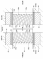
- the shaft seal structure (90) comprises a shaft seal housing (91), a thin plate (93) and a support (97).
- the shaft seal housing (91) is cylindrical and has an insertion hole (92).
- the drive shaft (41) is inserted through the central portion of the insertion hole (92).
- a thin plate (93) and a support (97) are accommodated in the insertion hole (92).
- the support (97) is located inside the insertion hole (92).
- the thin plate (93) is located on the center side (drive shaft (41) side) of the insertion hole (92).
- the thin plate (93) is cylindrically formed.
- the inner peripheral surface of the thin plate (93) faces the outer peripheral surface of the drive shaft (41).
- the thin plate (93) is a member made of metal and has flexibility.
- One end of the thin plate (93) in the circumferential direction forms a protruding piece (94) that is bent toward the outer periphery.
- the protruding piece (94) enters the support (97).
- the lamella (93) is thereby fixed to the support (97).
- the support (97) is cylindrical.
- a support (97) is arranged between the shaft seal housing (91) and the lamella (93).
- the support (97) elastically supports the thin plate (93).
- the support (97) of this example is composed of a metal mesh member (98).
- the mesh member (98) is composed of an aggregate of wire rods such as metal bundles (metal wool).
- the wire rod density of the mesh member (98) forming the support (97) is higher than the wire rod density of the mesh member (88) forming the back foil (87) of the radial bearing (80).
- the wire density of the mesh member (98) forming the support (97) may be the same as or lower than the wire density of the mesh member (88) forming the back foil (87).
- the support (97) having such a configuration suppresses the flow of gas in the axial direction according to the density of the wire.
- a predetermined gap (G2) is set between the thin plate (93) of the shaft sealing structure (90) and the drive shaft (41).
- the width (d2) of the gap (G2) between the lamella (93) and the drive shaft (41) is equal to the gap (G1) between the top foil (83) of the radial bearing (80) and the drive shaft (41) is set wider than the width (d1) of
- the width (d2) of the gap (G2) between the thin plate (93) and the drive shaft (41) is, for example, approximately 50 ⁇ m to 100 ⁇ m.
- the cooling gas flow path (120) of this example is divided into a first space (S1) and a second space (S2) and provided in two systems.
- the two gas flow paths (120) are a first gas flow path (120A) and a second gas flow path (120B).
- the first gas flow path (120A) is a flow path for supplying gas coolant to the thrust bearing (70) and the first radial bearing (80A).
- the second gas flow path (120B) is a flow path for supplying gas refrigerant to the second radial bearing (80B).
- the first gas flow path (120A) includes a first introduction flow path (121a) formed in the casing (20), a first upstream flow path (122a), a thrust plate (44) and a thrust bearing (70). , a gap between the thrust bearing (70) and the first radial bearing (80A), and the drive shaft (41), the first downstream flow path (123a), and the casing (20). and a first discharge channel (124a).
- a plurality of first introduction flow paths (121a) and a plurality of first discharge flow paths (124a) are provided. Each of the first introduction channel (121a) and the first discharge channel (124a) may be one.
- the first introduction channel (121a) introduces gas refrigerant from the outside into the first space (S1) of the casing (20).
- One end of the first introduction channel (121a) opens to the outside of the casing (20) and is connected to the first branch pipe (13c).
- the other end of the first introduction channel (121a) opens into the first upstream channel (122a).
- the first discharge channel (124a) discharges gas refrigerant from the first space (S1) of the casing (20) to the outside.
- One end of the first discharge channel (124a) opens into the first downstream channel (123a).
- the other end of the first discharge channel (124a) opens to the outside of the casing (20) and is connected to the first return pipe (14c).
- the gas refrigerant that has flowed through the branch circuit (13) is introduced into the first upstream flow path (122a) from the first introduction flow path (121a) through the first branch pipe (13c). After flowing through the first upstream flow path (122a), the gas refrigerant flows through the thrust bearing (70) and the first radial bearing (80A) into the first downstream flow path (123a). Then, the gas refrigerant that has flowed through the first downstream channel (123a) is discharged from the first discharge channel (124a) to the first return pipe (14c). The thrust bearing (70) and the first radial bearing (80A) are cooled by gas refrigerant flowing through the first gas flow path (120A).
- gas refrigerant passing through the thrust bearing (70) and the first radial bearing (80A) flows into the gap between the second base member (77) and the drive shaft (41), the thrust plate (44) and the second base member (77), between the thrust plate (44) and the spacer (74), between the thrust plate (44) and the first base member (71) It flows in order through the gap, the gap between the first base member (71) and the drive shaft (41), and the gap between the first radial bearing (80A) and the drive shaft (41).
- the gap between the thrust plate (44) and the second base member (77) includes the gap between the second top foil (75) and the thrust plate (44) and the gap between the second back foil (76) and the second base member (77).
- 2 includes the gap between the base member (77).
- the gap between the thrust plate (44) and the first base member (71) includes the gap between the first top foil (75) and the thrust plate (44) and the gap between the first back foil (76) and the first base member (71). 1 includes a gap with the base member (77).
- the second gas flow path (120B) includes a second introduction flow path (121b) formed in the casing (20), a second upstream flow path (122b), a second radial bearing (80B) and a drive shaft ( 41), a second downstream channel (123b), and a second discharge channel (124b) formed in the casing (20).
- a plurality of each of the second introduction flow paths (121b) and the second discharge flow paths (124b) are provided.
- Each of the second introduction channel (121b) and the second discharge channel (124b) may be one.
- the second introduction channel (121b) introduces gas refrigerant from the outside into the second space (S2) of the casing (20).
- One end of the second introduction channel (121b) opens to the outside of the casing (20) and is connected to the second branch pipe (13d).
- the other end of the second introduction channel (121b) opens into the second upstream channel (122b).
- the second discharge channel (124b) discharges gas refrigerant from the second space (S2) of the casing (20) to the outside.
- One end of the second discharge channel (124b) opens into the second downstream channel (122b).
- the other end of the second discharge channel (124b) opens to the outside of the casing (20) and is connected to the second return pipe (14d).
- the gas refrigerant that has flowed through the branch circuit (13) is introduced into the second upstream flow path (122b) from the second introduction flow path (121b) through the second branch pipe (13d).
- the gas refrigerant that has flowed through the second upstream flow path (122b) flows to the second downstream flow path (123b) via the second radial bearing (80B).
- Gas refrigerant passing through the second radial bearing (80B) flows through the gap between the second radial bearing (80B) and the drive shaft (41). Then, the gas refrigerant that has flowed through the second downstream channel (123b) is discharged from the second discharge channel (124b) to the second return pipe (14d).
- the second radial bearing (80B) is cooled by gas refrigerant flowing through the second gas flow path (120B).
- Embodiment 1 In the shaft seal structure (90) of Embodiment 1, the cylindrical thin plate (93) is elastically supported on the outer peripheral side by the support (97) in the insertion hole (92) of the shaft seal housing (91). .
- the thin plate (93) flexes adaptively.
- the bent thin plate (93) is restored by the support of the support (97) when the drive shaft (41) returns to its position.
- a gap (G2) is secured between the drive shaft (41) and the thin plate (93). Therefore, the width (d2) of the gap (G2) between the drive shaft (41) and the thin plate (93) can be reduced.
- the support (97) restricts gas flow in the axial direction between the shaft seal housing (91) and the thin plate (93). Therefore, the amount of gas leakage in the shaft sealing structure (90) can be reduced.
- the support (97) is composed of the mesh member (98).
- the amount of gas leakage in the shaft sealing structure (90) can be adjusted according to the density of the wire rods forming the mesh member (98).
- the first shaft seal structure (90A) is arranged between the high pressure impeller chamber (23) and the electric motor chamber (26). The amount of gas leaking from the high-pressure impeller chamber (23) to the electric motor chamber (26) is reduced by the first shaft seal structure (90A).
- the second shaft sealing structure (90B) is arranged between the low-pressure impeller chamber (24) and the electric motor chamber (26). The amount of gas leaking from the low-pressure impeller chamber (24) to the electric motor chamber (26) is reduced by the second shaft seal structure (90B).
- gas refrigerant as cooling gas is supplied to the thrust bearing (70) and the first radial bearing (80A) through the first gas flow path (120A).
- the thrust bearing (70) and the first radial bearing (80A) are cooled by gas refrigerant supplied through the first gas flow path (120A). This can prevent the thrust bearing (70) and the first radial bearing (80A) from being seized.
- gas refrigerant as cooling gas is supplied to the second radial bearing (80B) through the second gas flow path (120B).
- the second radial bearing (80B) is cooled by gas refrigerant supplied through the second gas flow path (120B).
- foil gas bearings are employed for each of the thrust bearing (70), the first radial bearing (80A), and the second radial bearing (80B) that support the drive shaft (41) on the outer periphery. do.
- the foil gas bearing is advantageous in reducing the frictional heat generated in the bearing surface (84) and the amount of wear of the bearing surface due to the rotation of the drive shaft (41). It is suitable as a bearing for supporting (41).
- the width (d2) of the gap (G2) between the thin plate (93) of the shaft sealing structure (90) and the drive shaft (41) is the top of the radial bearing (80). It is set wider than the width (d1) of the gap (G1) between the foil (83) and the drive shaft (41). As a result, heat generated by the rotation of the drive shaft (41) in the shaft sealing structure (90) is reduced. As a result, seizure of the shaft sealing structure (90) can be suppressed.
- the compressor (2) described above is used in the refrigerant circuit (10). This contributes to higher efficiency of the refrigeration cycle performed in the refrigeration system (1).
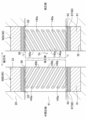
- the compressor (2) of the second embodiment differs from that of the first embodiment in the configuration of the shaft seal structure (90).
- the compressor (2) of this example is also used in a refrigeration system (1) similar to that of the first embodiment.
- the compressor (2) is configured in the same manner as in Embodiment 1 above except that the configuration of the shaft seal structure (90) is different from that in Embodiment 1 above. Therefore, only the shaft seal structure (90) having a different configuration in the compressor (2) will be described, and detailed descriptions of the same components will be omitted.
- the shaft sealing structure (90) of Embodiment 2 includes a shaft sealing housing (91), a thin plate (93), and a support (97).
- the shaft sealing housing (91) and the thin plate (93) are configured in the same manner as the shaft sealing housing (91) and the thin plate (93) of the shaft sealing structure (90) of the first embodiment.
- the support (97) in this example consists of a bump foil (100) and a flexible filler (105).
- a bump foil (100) is an example of an elastic member.
- the bump foil (100) is formed in a cylindrical shape.
- the bump foil (100) consists of a sheet of metal corrugated to form a flexible spring element.
- the bump foil (100) is provided with a plurality of protrusions (101) protruding radially inward.
- the plurality of protrusions (101) are circumferentially spaced from each other to form a wave shape.
- Each projection (101) constitutes a spring element and receives a lamella (93).
- the filler (105) is filled between the bump foil (100) and the shaft sealing housing (91) and between the bump foil (100) and the thin plate (93).
- the filler (105) is, for example, foam metal and has flexibility.
- a foam metal is a cellular structure formed by foaming a metal material and having a large number of cells.
- the foam metal used for the filler (105) may be a single cell body with independent cells or a continuous cell body with interconnected cells.
- the support body (97) having such a configuration suppresses gas flow in the axial direction between the shaft seal housing (91) and the thin plate (93).
- a joining margin (95) bent in the circumferential direction is provided at the tip of the projecting piece (94) of the thin plate (93).
- the protruding piece (94) enters the filler (105).
- the bond allowance (95) is then bonded to the bump foil (100).
- the lamella (93) is thereby fixed to the support (97).
- the support (97) is composed of the bump foil (100) and the filler (105).
- the thin plate (93) is elastically supported by a plurality of protrusions (101) provided on the bump foil (100).
- a filling material (105) is filled between the bump foil (100) and the shaft sealing housing (91) and between the bump foil (100) and the thin plate (93), so that gas flows through the gaps between them. can be inhibited.
- the filler (105) since the filler (105) is flexible, it deforms according to the bending of the thin plate (93).
- the shaft seal structure (90) of Embodiment 3 includes a shaft seal housing (91), a thin plate (93), and a support (97).
- the thin plate (93) is configured in the same manner as the shaft sealing housing (91) and the thin plate (93) forming the shaft sealing structure (90) of the first embodiment.
- the support (97) in this example is composed of a metal mesh member (110) and a flexible filler (115).
- the mesh member (110) is cylindrically formed.
- the mesh member (110) is made of a wire such as a metal bundle (metal wool).
- the wire density of the mesh member (110) forming the support (97) is such that the stiffness of the support (97) is equal to or lower than the stiffness of the bump foil (88) of the radial bearing (80). is preferably set to According to this, when the displacement progresses in the radial direction of the drive shaft (41), the first radial bearing (80A) and the second radial bearing (80B) bear the load from the drive shaft (41). Therefore, it is possible to prevent the thin plate (93) from contacting the drive shaft (41) and impairing the sealing performance of the shaft sealing structure (90).
- the wire density of the mesh member (110) forming the support (97) is set so that the rigidity of the support (97) is higher than the rigidity of the bump foil (88) of the radial bearing (80). good.
- the filler (115) is filled in the gaps of the mesh member (110).
- the filler (115) is, for example, foamed resin and has flexibility.
- a foamed resin is a cellular structure formed by foaming a synthetic resin and having a large number of cells.
- the foamed resin used for the filler (115) is an open-cell body in which cells are connected to each other.
- the foamed resin used for the filler (115) may be a single cell body with independent cells.
- the support body (97) having such a configuration suppresses gas flow in the axial direction between the shaft seal housing (91) and the thin plate (93).
- the support (97) is composed of the mesh member (110) and the filler (115). Since the filler (115) is filled in the gaps of the mesh member (110), the flow of gas through the gaps of the mesh member (110) can be blocked. In addition, since the filler (115) is flexible, it deforms according to the bending of the thin plate (93). Therefore, when the drive shaft (41) is displaced in the radial direction, the thin plate (93) is bent to follow the displacement of the drive shaft (41), and the gap between the drive shaft (41) and the thin plate (93) is formed. (G2) can be secured with good responsiveness.
- the first to third embodiments may be configured as follows.
- a plurality of of the first dynamic pressure grooves (130a) are formed in the compressor (2) of this first modification.
- the plurality of first dynamic pressure grooves (130a) are spaced apart from each other in the circumferential direction of the drive shaft (41).
- Each first dynamic pressure generating groove (130a) extends in a direction inclined with respect to the axial direction opposite to the rotational direction Dr of the drive shaft (41).
- the first dynamic pressure generating groove (130a) of this example is inclined so as to draw a curve from the low pressure side to the high pressure side.
- One end of each first dynamic pressure groove (130a) is open to the outside of the shaft sealing structure (90) on the low pressure side in the axial direction.
- the other end of each first dynamic pressure groove (130a) is closed inside the shaft sealing structure (90) on the high pressure side in the axial direction.
- Each first dynamic pressure groove (130a) generates dynamic pressure as the drive shaft (41) rotates. This dynamic pressure is generated by gas flowing through the first dynamic pressure groove (130a) from the low pressure side to the high pressure side, as indicated by a two-dot chain line in FIG.
- a plurality of second dynamic pressure grooves (130b) are formed in a portion of the drive shaft (41) facing the thin plate (93) of the second shaft sealing structure (90B).
- the plurality of second dynamic pressure grooves (130b) have a configuration symmetrical with the plurality of first dynamic pressure grooves (130a) via the rotor (42).
- the plurality of second dynamic pressure grooves (130b) are spaced apart from each other in the circumferential direction of the drive shaft (41).
- Each second dynamic pressure generating groove (130b) extends in a direction inclined with respect to the axial direction opposite to the rotational direction of the drive shaft (41).
- the second dynamic pressure generating groove (130b) of this example is inclined so as to draw a curve from the low pressure side to the intermediate pressure side.
- One end of each second dynamic pressure groove (130b) is open to the outside of the shaft sealing structure (90) on the low pressure side in the axial direction.
- the other end of each first dynamic pressure groove (130a) is closed inside the shaft sealing structure (90) on the intermediate pressure side in the axial direction.
- Each second dynamic pressure groove (130b) generates dynamic pressure as the drive shaft (41) rotates. This dynamic pressure is generated by gas flowing through the second dynamic pressure groove (130b) from the low pressure side to the intermediate pressure side, as indicated by a two-dot chain line in FIG.
- the first dynamic pressure grooves (130a) are formed in the outer peripheral surface facing the thin plate (93) of the drive shaft (41).
- gas flows through the first dynamic pressure groove (130a) from the low pressure side to the high pressure side so as to generate dynamic pressure.
- gas can be pushed back from the low pressure side to the high pressure side of the compressor (2) according to the rotation of the drive shaft (41). This is advantageous in reducing the amount of gas leaked from the first shaft seal structure (90A) provided in the compressor (2).
- the second dynamic pressure grooves (130b) are formed in the outer peripheral surface facing the thin plate (93) of the drive shaft (41).
- gas flows through the second dynamic pressure groove (130b) from the low pressure side to the intermediate pressure side so as to generate dynamic pressure.
- gas can be pushed back from the low pressure side of the compressor (2) to the intermediate pressure side in accordance with the rotation of the drive shaft (41). This is advantageous in reducing the amount of gas leaked from the second shaft seal structure (90B) provided in the compressor (2).
- the thin plate (93) of the first shaft sealing structure (90A) has a plurality of first hydrodynamic grooves (140a) on the inner peripheral surface thereof. It is formed.
- the plurality of first dynamic pressure grooves (140a) are spaced apart from each other in the circumferential direction of the drive shaft (41).
- Each first dynamic pressure generating groove (140a) extends axially in a direction inclined opposite to the rotational direction Dr of the drive shaft (41).
- the first dynamic pressure generating groove (140a) of this example inclines at the same angle over its entire length from the low pressure side toward the high pressure side.
- One end of each first dynamic pressure groove (140a) is open to the outside of the first shaft sealing structure (90A) on the low pressure side in the axial direction.
- the other end of each first dynamic pressure groove (140a) is closed inside the first shaft sealing structure (90A) on the high pressure side in the axial direction.
- Each first dynamic pressure groove (140a) generates dynamic pressure as the drive shaft (41) rotates. This dynamic pressure is generated by gas flowing through the first dynamic pressure groove (140a) from the low pressure side to the high pressure side, as indicated by a two-dot chain line in FIG.
- a plurality of second hydrodynamic grooves (140b) are formed on the inner peripheral surface of the thin plate (93) of the second shaft sealing structure (90B).
- the plurality of second dynamic pressure grooves (140b) have a configuration symmetrical with the plurality of first dynamic pressure grooves (140a) via the rotor (42).
- the plurality of second dynamic pressure grooves (140b) are spaced apart from each other in the circumferential direction of the drive shaft (41).
- Each second dynamic pressure generating groove (140b) extends axially in a direction inclined opposite to the rotational direction of the drive shaft (41).
- the second dynamic pressure groove (140b) of this example is inclined at the same angle over the entire length from the low pressure side toward the intermediate pressure side.
- One end of each second dynamic pressure groove (140b) is open to the outside of the second shaft sealing structure (90B) on the low pressure side in the axial direction.
- the other end of each second dynamic pressure groove (140b) is closed inside the second shaft sealing structure (90) on the intermediate pressure side in the axial direction.
- Each second dynamic pressure groove (140b) generates dynamic pressure as the drive shaft (41) rotates. This dynamic pressure is generated by gas flowing through the second dynamic pressure groove (140b) from the low pressure side to the intermediate pressure side, as indicated by a two-dot chain line in FIG.
- the first dynamic pressure grooves (140a) are formed in the inner peripheral surface of the thin plate (93) of the first shaft sealing structure (90A).
- gas flows through the first dynamic pressure groove (140a) from the low pressure side to the high pressure side so as to generate dynamic pressure.
- gas can be pushed back from the low pressure side to the high pressure side of the compressor (2) according to the rotation of the drive shaft (41). This is advantageous in reducing the amount of gas leaked from the first shaft seal structure (90A) provided in the compressor (2).
- the second dynamic pressure grooves (140b) are formed in the inner peripheral surface of the thin plate (93) of the second shaft sealing structure (90B).
- gas flows through the second dynamic pressure groove (140b) from the low pressure side to the intermediate pressure side so as to generate dynamic pressure.
- gas can be pushed back from the low pressure side of the compressor (2) to the intermediate pressure side in accordance with the rotation of the drive shaft (41). This is advantageous in reducing the amount of gas leaked from the second shaft seal structure (90B) provided in the compressor (2).
- the thin plate (93) of the shaft sealing structure (90) and the support (97) are in contact over the entire circumference.
- the entire outer peripheral surface of the thin plate (93) is adhered to the support (97) with an adhesive.
- the adhesion between the thin plate (93) and the support (97) may be partial as long as they are in contact with each other over the entire circumference.
- the thin plate (93) of the shaft sealing structure (90) and the support (97) are in contact with each other over the entire circumference.
- the channel through which the gas flows in the axial direction can be closed. This is advantageous in reducing the amount of gas leaked from the shaft seal structure (90).
- one cooling gas flow path (120) is provided in common for the first space (S1) and the second space (S2).
- the gas flow path (120) is a flow path for supplying cooling gas to the thrust bearing (70), the first radial bearing (80A), the electric motor (40) and the second radial bearing (80B).
- the gas flow path (120) of this example includes an introduction flow path (121) formed in the casing (20), an upstream flow path (125), and a space between the thrust plate (44) and the thrust bearing (70). clearance, clearance between thrust bearing (70) and first radial bearing (80A) and drive shaft (41), first relay passage (126), between rotor (42) and stator (43) , the second relay flow path (127), the gap between the second radial bearing (80B) and the drive shaft (41), the downstream flow path (128), and the discharge flow formed in the casing (20) road (124) and A plurality of each of the introduction channel (121) and the discharge channel (124) are provided. Each of the introduction channel (121) and the discharge channel (124) may be one.
- the introduction passageway (121) introduces the gas refrigerant as cooling gas into the motor room (26) of the casing (20).
- One end of the introduction channel (121) constitutes an inlet opening to the outside of the casing (20) and is connected to the branch pipe (13a).
- the other end of the introduction channel (121) opens into the upstream channel (125).
- the upstream flow path (125) is one of the two spaces that define the first space (S1) by the first holding member (61) and is located on the high-pressure impeller chamber (23) side.
- the first relay flow path (126) is the other of the two spaces located on the rotor (42) side.
- the second relay flow path (127) is one of the two spaces that define the second space (S2) by the second holding member (66) and is located on the rotor (42) side.
- the downstream flow path (123) is the other of the two spaces located on the low-pressure impeller chamber (24) side.
- the discharge channel (124) discharges the gas refrigerant from the motor room (26) of the casing (20) to the outside.
- One end of the discharge channel (124) opens into the downstream channel (128).
- the other end of the discharge channel (124) forms an outlet opening to the outside of the casing (20) and is connected to the return pipe (14a).
- the gas refrigerant that has flowed through the branch circuit (13) is introduced as cooling gas from the introduction channel (121) into the upstream channel (125) through the branch pipe (13a).
- the gas refrigerant that has flowed through the upstream flow path (125) flows through the thrust bearing (70) and the first radial bearing (80A) into the first relay flow path (126).
- the gas refrigerant that has flowed through the first relay flow path (126) flows through the gap between the rotor (42) and the stator (43) into the second relay flow path (127).
- the gas refrigerant that has flowed through the second relay flow path (127) flows into the downstream flow path (128) via the second radial bearing (80B).
- the gas refrigerant that has flowed through the downstream channel (128) is discharged from the discharge channel (124) to the return pipe (14a).
- the thrust bearing (70), the first radial bearing (80A) and the second radial bearing (80B) are cooled by gas coolant flowing through the gas flow path (120).
- the cooling gas flow path (120) is provided in common for the first space (S1) and the second space (S2). This makes the configuration of the gas flow path (120) simpler than when the gas flow path (120) for cooling is provided separately for the first space (S1) and the second space (S2). It is advantageous to
- the gas channel (120) also includes a gap between the rotor (42) and the stator (43). Thereby, not only the bearing (60) but also the electric motor (40) can be cooled by the gas refrigerant flowing through the gas flow path (120).
- the refrigerant circulating in the refrigerant circuit (10) is used as the cooling gas for cooling the bearing (60), but the present invention is not limited to this.
- the cooling gas flowing through the cooling gas flow path (120) may be refrigerant circulating in a gas circuit independent of the refrigerant circulating in the refrigerant circuit (10) or other cooling gas.
- the bump foil (100) having a plurality of protrusions (101) was taken as an example of the elastic member forming the support (97) of the shaft sealing structure (90), but the present invention is not limited to this.
- the bump foil (100) may have other configurations, such as being made of a thin plate having a plurality of cantilever spring-like plate pieces as spring elements.
- the bump foil (100) is just one example of an elastic member, which can be a cylinder provided with a plurality of spring elements for receiving thin plates.
- the compressor (2) is a two-stage centrifugal compressor (2), but it is not limited to this.
- the compressor (2) may be a single stage centrifugal compressor or other turbo compressor such as an axial compressor.
- the shaft sealing structure (90) can also be applied to a rotating machine having a rotating shaft other than the compressor (2).
- the object to be sealed by the shaft sealing structure (90) of the present disclosure is gas, but it is not limited to this.
- the shaft sealing structure (90) of the present disclosure is intended for sealing not only gas but all fluids including liquid.
- the shaft sealing structure (90) of the present disclosure can also be applied to pumps, water turbines, etc. that deliver liquid.
- the present disclosure is useful for shaft seal structures, compressors, and refrigeration systems.
Landscapes
- Engineering & Computer Science (AREA)
- General Engineering & Computer Science (AREA)
- Mechanical Engineering (AREA)
- Physics & Mathematics (AREA)
- Thermal Sciences (AREA)
- Fluid Mechanics (AREA)
- Structures Of Non-Positive Displacement Pumps (AREA)
- Sealing Using Fluids, Sealing Without Contact, And Removal Of Oil (AREA)
Abstract
Description
図1に示すように、本開示の圧縮機(2)は、冷凍装置(1)に設けられる。
冷凍装置(1)は、冷媒回路(10)を有する。冷媒回路(10)には、冷媒が充填される。本例の圧縮機(2)で圧縮される流体は、冷媒である。例えば、冷媒は、HFC(Hydro Fluoro Carbon)冷媒、HFO(Hydro Fluoro Olefin)冷媒、HFC冷媒とHFO冷媒との混合冷媒、CF3I(Trifluoroiodomethane)冷媒、二酸化炭素冷媒、および炭化水素冷媒のうちいずれか1つである。
上述したように、圧縮機(2)は、冷媒回路(10)を構成する。圧縮機(2)は、低圧のガス冷媒を吸引し、そのガス冷媒を圧縮する。圧縮機(2)は、圧縮した後の高圧のガス冷媒を吐出する。なお、以下の説明においては、圧縮機(2)の駆動軸(41)に沿う方向を「軸方向」と称し、軸方向に垂直な方向を「径方向」と称し、駆動軸(41)の周囲に沿う方向を「周方向」と称する。
ケーシング(20)は、両端が閉塞された概ね円筒状の密閉容器である。ケーシング(20)は、その中心線が実質的に水平となる姿勢に設置される。ケーシング(20)は、軸方向に延び、内部空間(S)を有する。ケーシング(20)の内部空間(S)は、軸方向における一方側で第1壁部(21)によって区画され、軸方向における他方側で第2壁部(22)によって区画される。
電動機(40)は、圧縮機構(50)の駆動源である。電動機(40)は、電動機室(26)に収容される。電動機(40)は、例えば永久磁石同期型モータ(PMSM:Permanent Magnet Synchronous Motor)である。電動機(40)は、駆動軸(41)と、回転子(42)と、固定子(43)とを有する。電動機(40)は、駆動軸(41)の軸心(X)の方向(軸方向)が水平向きとなる姿勢に設けられる。駆動軸(41)は、回転軸の一例である。
圧縮機構(50)は、電動機(40)の駆動により吸入したガス冷媒を圧縮する。圧縮機構(50)は、高圧インペラ(51)と、低圧インペラ(52)とを有する。高圧インペラ(51)は、高圧インペラ室(23)に収容される。高圧インペラ(51)は、駆動軸(41)の一端部に固定される。低圧インペラ(52)は、低圧インペラ室(24)に収容される。低圧インペラ(52)は、駆動軸(41)の他端部に固定される。
圧縮機(2)は、軸受(60)として、スラスト軸受(70)と、第1ラジアル軸受(80A)と、第2ラジアル軸受(80B)とを備える。スラスト軸受(70)および第1ラジアル軸受(80A)は、第1保持部材(61)に保持される。第1保持部材(61)は、第1空間(S1)に配置される。第2ラジアル軸受(80B)は、第2保持部材(66)に保持される。第2保持部材(66)は、第2空間(S2)に配置される。
本例のスラスト軸受(70)は、フォイル気体軸受である。図3に示すように、スラスト軸受(70)は、第1ベース部材(71)と、第1バックフォイル(72)と、第1トップフォイル(73)と、スペーサ(74)と、第2トップフォイル(75)と、第2バックフォイル(76)と、第2ベース部材(77)とを備える。第1ベース部材(71)および第2ベース部材(77)は、互いに組み合わせられて軸受ハウジング(78)を構成する。
本例の第1ラジアル軸受(80A)および第2ラジアル軸受(80B)はいずれも、フォイル気体軸受である。第1ラジアル軸受(80A)および第2ラジアル軸受(80B)には、同じ構成のラジアル軸受(80)が用いられる。ラジアル軸受(80)の構成を、第1ラジアル軸受(80A)を例にして図4に示す。ラジアル軸受(80)は、軸受ハウジング(81)と、トップフォイル(83)と、バックフォイル(87)とを備える。
図2に示すように、圧縮機(2)は、軸封構造(90)として、第1軸封構造(90A)と、第2軸封構造(90B)とを備える。第1軸封構造(90A)は、第1壁部(21)の駆動軸(41)周りの部分に設けられる。第2軸封構造(90B)は、第2壁部(22)の駆動軸(41)周りの部分に設けられる。
図2に示すように、本例の冷却用のガス流路(120)は、第1空間(S1)と第2空間(S2)とに分けて2系統設けられる。2系統のガス流路(120)は、第1ガス流路(120A)と、第2ガス流路(120B)とである。第1ガス流路(120A)は、スラスト軸受(70)および第1ラジアル軸受(80A)にガス冷媒を供給するための流路である。第2ガス流路(120B)は、第2ラジアル軸受(80B)にガス冷媒を供給するための流路である。
この実施形態1の軸封構造(90)では、円筒状の薄板(93)が軸封ハウジング(91)の挿通孔(92)内で支持体(97)により外周側を弾性的に支持される。駆動軸(41)が半径方向へ変位すると、薄板(93)が適応的に撓む。撓んだ薄板(93)は、駆動軸(41)の位置が戻ると、支持体(97)の支持により復帰する。こうして、駆動軸(41)と薄板(93)との間の隙間(G2)が確保される。よって、駆動軸(41)と薄板(93)との間の隙間(G2)の幅(d2)を小さくできる。そして、支持体(97)は、軸封ハウジング(91)と薄板(93)との間で軸方向へのガスの流れを抑制する。したがって、軸封構造(90)でのガスの漏れ量を低減できる。
この実施形態2の圧縮機(2)は、軸封構造(90)の構成が上記実施形態1と異なる。本例の圧縮機(2)も、上記実施形態1と同様な冷凍装置(1)に使用される。なお、以降の各実施形態では、圧縮機(2)について、軸封構造(90)の構成が上記実施形態1と異なる他は、上記実施形態1と同様に構成される。よって、圧縮機(2)で構成の異なる軸封構造(90)についてのみ説明し、同一の構成箇所の詳細な説明は省略する。
この実施形態2の軸封構造(90)では、支持体(97)がバンプフォイル(100)と充填材(105)とによって構成される。薄板(93)は、バンプフォイル(100)に設けられた複数の凸部(101)により弾性的に支持される。バンプフォイル(100)と軸封ハウジング(91)との間およびバンプフォイル(100)と薄板(93)との間には、充填材(105)が充填されるので、それらの隙間を通じてガスが流れるのを阻害できる。また、充填材(105)は、柔軟なため、薄板(93)の撓みに応じて変形する。よって、駆動軸(41)が半径方向へ変位したときには、その駆動軸(41)の変位に薄板(93)を追随させて撓ませ、駆動軸(41)と薄板(93)との間の隙間(G2)を応答性よく確保できる。
図7に示すように、この実施形態3の軸封構造(90)は、軸封ハウジング(91)と、薄板(93)と、支持体(97)とを備える、軸封ハウジング(91)および薄板(93)は、上記実施形態1の軸封構造(90)をなす軸封ハウジング(91)および薄板(93)と同様に構成される。本例の支持体(97)は、金属製のメッシュ部材(110)と、柔軟な充填材(115)とによって構成される。
この実施形態3の軸封構造(90)では、支持体(97)がメッシュ部材(110)と充填材(115)とによって構成される。メッシュ部材(110)の隙間には、充填材(115)が充填されるので、メッシュ部材(110)の隙間をガスが流れるのを阻害できる。また、充填材(115)は、柔軟なため、薄板(93)の撓みに応じて変形する。よって、駆動軸(41)が半径方向へ変位したときには、その駆動軸(41)の変位に薄板(93)を追随させて撓ませ、駆動軸(41)と薄板(93)との間の隙間(G2)を応答性よく確保できる。
上記実施形態1~3については、以下のような構成としてもよい。
図8に示すように、この第1変形例の圧縮機(2)では、駆動軸(41)の外周面のうち第1軸封構造(90A)の薄板(93)と対向する部分に、複数の第1動圧溝(130a)が形成される。複数の第1動圧溝(130a)は、駆動軸(41)の周方向に互いに間隔をあけて設けられる。各第1動圧溝(130a)は、軸方向に対して駆動軸(41)の回転方向Drとは反対側に傾斜した方向に延びる。
図9に示すように、この第2変形例の圧縮機(2)では、第1軸封構造(90A)の薄板(93)の内周面に、複数の第1動圧溝(140a)が形成される。複数の第1動圧溝(140a)は、駆動軸(41)の周方向に互いに間隔をあけて設けられる。各第1動圧溝(140a)は、軸方向にして駆動軸(41)の回転方向Drとは反対側に傾斜した方向に延びる。
この第3変形例の圧縮機(2)では、軸封構造(90)の薄板(93)と支持体(97)とが全周に亘って接する。例えば、薄板(93)の外周面は、接着剤により全体に亘って支持体(97)に接着される。薄板(93)と支持体(97)との接着は、両者が全周に亘って接するようになれば、部分的であってもよい。
図10に示すように、圧縮機(2)において、冷却用のガス流路(120)は、第1空間(S1)と第2空間(S2)とで共通に1系統設けられる。ガス流路(120)は、スラスト軸受(70)、第1ラジアル軸受(80A)、電動機(40)および第2ラジアル軸受(80B)に冷却ガスを供給するための流路である。
G2 隙間
1 冷凍装置
2 圧縮機
10 冷媒回路
40 電動機
41 駆動軸(回転軸)
42 回転子
50 圧縮機構
60 軸受
80 ラジアル軸受(フォイル気体軸受)
83 トップフォイル
89 ガス膜
90 軸封構造
92 挿通孔
91 軸封ハウジング(ハウジング)
93 薄板
97 支持体
98 メッシュ部材
100 バンプフォイル(弾性部材)
105 充填材
110 メッシュ部材
115 充填材
120 ガス流路
130a 第1動圧溝(動圧溝)
130b 第2動圧溝(動圧溝)
140a 第1動圧溝(動圧溝)
140b 第2動圧溝(動圧溝)
Claims (14)
- 回転軸(41)が挿通される挿通孔(92)を有するハウジング(91)と、
前記挿通孔(92)に収容された、可撓性を有する円筒状の薄板(93)と、
前記ハウジング(91)と前記薄板(93)との間に配置され、前記薄板(93)を弾性的に支持する支持体(97)と、を備え、
前記薄板(93)の内周面は、前記回転軸(41)の外周面に対向して、該回転軸(41)との間に隙間(G2)を形成し、
前記支持体(97)は、前記回転軸(41)に沿う方向への流体の流れを抑制する、軸封構造。 - 請求項1に記載の軸封構造において、
前記支持体(97)は、メッシュ部材(98)によって構成される、軸封構造。 - 請求項1に記載の軸封構造において、
前記支持体(97)は、前記薄板(93)を受ける複数のばね要素(101)が設けられた円筒状の弾性部材(100)と、該弾性部材(100)と前記ハウジング(91)および前記薄板(93)との間に充填された柔軟な充填材(105)とによって構成される、軸封構造。 - 請求項1に記載の軸封構造において、
前記支持体(97)は、メッシュ部材(110)と、該メッシュ部材(110)の空隙に充填された柔軟な充填材(115)とによって構成される、軸封構造。 - 請求項1~4のいずれか1項に記載の軸封構造(90)と、
前記軸封構造(90)によって軸封された前記回転軸(41)を有する電動機(40)と、
前記電動機(40)の駆動により吸入した流体を圧縮する圧縮機構(50)と、
前記圧縮機構(50)との間に前記軸封構造(90)を介する前記電動機(40)の回転子(42)側の位置に設けられ、前記回転軸(41)を外周で回転可能に支持する軸受(60)と、を備える、圧縮機。 - 請求項5に記載の圧縮機において、
前記軸受(60)に冷却ガスを供給するガス流路(120)が設けられる、圧縮機。 - 請求項5または6に記載の圧縮機において、
前記軸受(60)は、フォイル気体軸受(80)であり、
前記フォイル気体軸受(80)は、
可撓性を有するトップフォイル(83)を備え、
前記トップフォイル(83)と前記回転軸(41)との間に隙間(G1)を形成し、
前記隙間(G1)に生じるガス膜(89)により前記回転軸(41)を支持する、圧縮機。 - 請求項7に記載の圧縮機において、
前記軸封構造(90)の前記薄板(93)と前記回転軸(41)との間の隙間(G2)の幅(d2)は、前記軸受(80)の前記トップフォイル(83)と前記回転軸(41)との間の隙間(G1)の幅(d1)よりも広く設定される、圧縮機。 - 請求項5~8のいずれか1項に記載の圧縮機において、
前記回転軸(41)の前記薄板(93)と対向する外周面には、当該回転軸(41)の回転に伴い前記回転子(42)側から前記圧縮機構(50)側へガスが流れることで動圧を発生させる動圧溝(130a,130b)が形成される、圧縮機。 - 請求項5~9のいずれか1項に記載の圧縮機において、
前記薄板(93)の内周面には、前記回転軸(41)の回転に伴い前記回転子(42)側から前記圧縮機構(50)側へガスが流れることで動圧を発生させる動圧溝(140b,140b)が形成される、圧縮機。 - 請求項5~10のいずれか1項に記載の圧縮機において、
前記薄板(93)と前記支持体(97)とは、全周に亘って接する、圧縮機。 - 遠心圧縮機(2)である、請求項5~11のいずれか1項に記載の圧縮機。
- 請求項5~12のいずれか1項に記載の圧縮機において、
前記ガスは、HFC冷媒、HFO冷媒、HFC冷媒とHFO冷媒との混合冷媒、CF3I冷媒、二酸化炭素冷媒、および炭化水素冷媒のうちいずれか1つである、圧縮機。 - 請求項5~13のいずれか1項に記載の圧縮機(2)を備え、
前記圧縮機(2)は、冷媒を循環させて冷凍サイクルを行う冷媒回路(10)を構成する、冷凍装置。
Priority Applications (3)
| Application Number | Priority Date | Filing Date | Title |
|---|---|---|---|
| EP22883277.0A EP4400727A4 (en) | 2021-10-18 | 2022-09-16 | SHAFT SEAL STRUCTURE, COMPRESSOR AND REFRIGERANT DEVICE |
| CN202280069488.6A CN118159744A (zh) | 2021-10-18 | 2022-09-16 | 轴封结构、压缩机及制冷装置 |
| US18/637,247 US20240263638A1 (en) | 2021-10-18 | 2024-04-16 | Shaft seal structure, compressor, and refrigeration apparatus |
Applications Claiming Priority (2)
| Application Number | Priority Date | Filing Date | Title |
|---|---|---|---|
| JP2021-170388 | 2021-10-18 | ||
| JP2021170388A JP7364926B2 (ja) | 2021-10-18 | 2021-10-18 | 軸封構造、圧縮機および冷凍装置 |
Related Child Applications (1)
| Application Number | Title | Priority Date | Filing Date |
|---|---|---|---|
| US18/637,247 Continuation US20240263638A1 (en) | 2021-10-18 | 2024-04-16 | Shaft seal structure, compressor, and refrigeration apparatus |
Publications (1)
| Publication Number | Publication Date |
|---|---|
| WO2023067967A1 true WO2023067967A1 (ja) | 2023-04-27 |
Family
ID=86059013
Family Applications (1)
| Application Number | Title | Priority Date | Filing Date |
|---|---|---|---|
| PCT/JP2022/034828 Ceased WO2023067967A1 (ja) | 2021-10-18 | 2022-09-16 | 軸封構造、圧縮機および冷凍装置 |
Country Status (5)
| Country | Link |
|---|---|
| US (1) | US20240263638A1 (ja) |
| EP (1) | EP4400727A4 (ja) |
| JP (1) | JP7364926B2 (ja) |
| CN (1) | CN118159744A (ja) |
| WO (1) | WO2023067967A1 (ja) |
Families Citing this family (1)
| Publication number | Priority date | Publication date | Assignee | Title |
|---|---|---|---|---|
| DE102024112171A1 (de) * | 2024-04-30 | 2025-10-30 | Everllence Se | Thermodynamisches Kreisprozesssystem mit einer Kühlung einer elektrischen Maschine desselben |
Citations (5)
| Publication number | Priority date | Publication date | Assignee | Title |
|---|---|---|---|---|
| JP2007162493A (ja) * | 2005-12-09 | 2007-06-28 | Ntn Corp | 圧縮膨張タービンシステム |
| JP2010014051A (ja) | 2008-07-04 | 2010-01-21 | Hitachi Plant Technologies Ltd | 遠心圧縮機 |
| JP2012251605A (ja) * | 2011-06-03 | 2012-12-20 | Ihi Corp | 回転軸の支持構造 |
| WO2017014316A1 (ja) * | 2015-07-23 | 2017-01-26 | 株式会社 豊田自動織機 | 遠心圧縮機 |
| WO2018155318A1 (ja) * | 2017-02-22 | 2018-08-30 | イーグル工業株式会社 | シール装置 |
Family Cites Families (2)
| Publication number | Priority date | Publication date | Assignee | Title |
|---|---|---|---|---|
| WO2012117792A1 (ja) * | 2011-02-28 | 2012-09-07 | Ntn株式会社 | フォイル軸受 |
| JP2017089384A (ja) * | 2014-03-19 | 2017-05-25 | 株式会社豊田自動織機 | 電動ターボ式圧縮機 |
-
2021
- 2021-10-18 JP JP2021170388A patent/JP7364926B2/ja active Active
-
2022
- 2022-09-16 CN CN202280069488.6A patent/CN118159744A/zh active Pending
- 2022-09-16 EP EP22883277.0A patent/EP4400727A4/en active Pending
- 2022-09-16 WO PCT/JP2022/034828 patent/WO2023067967A1/ja not_active Ceased
-
2024
- 2024-04-16 US US18/637,247 patent/US20240263638A1/en active Pending
Patent Citations (5)
| Publication number | Priority date | Publication date | Assignee | Title |
|---|---|---|---|---|
| JP2007162493A (ja) * | 2005-12-09 | 2007-06-28 | Ntn Corp | 圧縮膨張タービンシステム |
| JP2010014051A (ja) | 2008-07-04 | 2010-01-21 | Hitachi Plant Technologies Ltd | 遠心圧縮機 |
| JP2012251605A (ja) * | 2011-06-03 | 2012-12-20 | Ihi Corp | 回転軸の支持構造 |
| WO2017014316A1 (ja) * | 2015-07-23 | 2017-01-26 | 株式会社 豊田自動織機 | 遠心圧縮機 |
| WO2018155318A1 (ja) * | 2017-02-22 | 2018-08-30 | イーグル工業株式会社 | シール装置 |
Non-Patent Citations (1)
| Title |
|---|
| See also references of EP4400727A4 |
Also Published As
| Publication number | Publication date |
|---|---|
| JP7364926B2 (ja) | 2023-10-19 |
| JP2023060670A (ja) | 2023-04-28 |
| EP4400727A4 (en) | 2024-12-18 |
| US20240263638A1 (en) | 2024-08-08 |
| CN118159744A (zh) | 2024-06-07 |
| EP4400727A1 (en) | 2024-07-17 |
Similar Documents
| Publication | Publication Date | Title |
|---|---|---|
| CN113557365B (zh) | 箔轴承系统及包括该箔轴承系统的压缩机 | |
| US6155802A (en) | Turbo compressor | |
| JP2019199975A (ja) | 冷凍サイクル装置 | |
| US6210130B1 (en) | Rotary compressor, refrigerating cycle using the compressor, and refrigerator using the compressor | |
| US20240263638A1 (en) | Shaft seal structure, compressor, and refrigeration apparatus | |
| CN111894890B (zh) | 用于压缩机的密封组件 | |
| US20250020135A1 (en) | Turbomachine | |
| JP2018123759A (ja) | ターボ圧縮機 | |
| JP5543192B2 (ja) | 電動圧縮機及びそれを用いた蒸気圧縮式冷凍機 | |
| US20240068382A1 (en) | Rotary machine and refrigeration device using same | |
| JP7393712B2 (ja) | 遠心式圧縮機および冷凍装置 | |
| US11598347B2 (en) | Impeller with external blades | |
| JP2012239284A (ja) | ロータの端部材、該ロータ端部材を備えたモータおよび該モータを備えた圧縮機 | |
| CN113123976B (zh) | 压缩机及具有该压缩机的涡轮制冷机 | |
| CN223578242U (zh) | 水蒸气压缩机及水蒸气压缩系统 | |
| JP7598046B2 (ja) | ターボ流体機械、及び冷凍装置 | |
| JP7748584B2 (ja) | 膨張タービン | |
| JP2019143510A (ja) | ターボ圧縮機 | |
| JP7398332B2 (ja) | ターボ圧縮機 | |
| JP2018115671A (ja) | 回転機械及び回転機械の潤滑システム | |
| JP2018189165A (ja) | 軸受装置及びターボ機械 | |
| JP2023150969A (ja) | 遠心式圧縮機および冷凍装置 | |
| JP2024130526A (ja) | 冷凍機 | |
| KR20240132867A (ko) | 터보 압축기 및 이를 구비한 냉동사이클장치 | |
| JP2008082294A (ja) | 圧縮機および冷媒回路装置 |
Legal Events
| Date | Code | Title | Description |
|---|---|---|---|
| 121 | Ep: the epo has been informed by wipo that ep was designated in this application |
Ref document number: 22883277 Country of ref document: EP Kind code of ref document: A1 |
|
| WWE | Wipo information: entry into national phase |
Ref document number: 2022883277 Country of ref document: EP |
|
| ENP | Entry into the national phase |
Ref document number: 2022883277 Country of ref document: EP Effective date: 20240408 |
|
| WWE | Wipo information: entry into national phase |
Ref document number: 202280069488.6 Country of ref document: CN |
|
| NENP | Non-entry into the national phase |
Ref country code: DE |