WO2023068114A1 - ステップ検知ユニット - Google Patents
ステップ検知ユニット Download PDFInfo
- Publication number
- WO2023068114A1 WO2023068114A1 PCT/JP2022/037906 JP2022037906W WO2023068114A1 WO 2023068114 A1 WO2023068114 A1 WO 2023068114A1 JP 2022037906 W JP2022037906 W JP 2022037906W WO 2023068114 A1 WO2023068114 A1 WO 2023068114A1
- Authority
- WO
- WIPO (PCT)
- Prior art keywords
- detection
- information
- unit
- area
- sensor
- Prior art date
- Legal status (The legal status is an assumption and is not a legal conclusion. Google has not performed a legal analysis and makes no representation as to the accuracy of the status listed.)
- Ceased
Links
Images









Classifications
-
- A—HUMAN NECESSITIES
- A63—SPORTS; GAMES; AMUSEMENTS
- A63F—CARD, BOARD, OR ROULETTE GAMES; INDOOR GAMES USING SMALL MOVING PLAYING BODIES; VIDEO GAMES; GAMES NOT OTHERWISE PROVIDED FOR
- A63F13/00—Video games, i.e. games using an electronically generated display having two or more dimensions
- A63F13/20—Input arrangements for video game devices
- A63F13/21—Input arrangements for video game devices characterised by their sensors, purposes or types
- A63F13/214—Input arrangements for video game devices characterised by their sensors, purposes or types for locating contacts on a surface, e.g. floor mats or touch pads
-
- A—HUMAN NECESSITIES
- A63—SPORTS; GAMES; AMUSEMENTS
- A63F—CARD, BOARD, OR ROULETTE GAMES; INDOOR GAMES USING SMALL MOVING PLAYING BODIES; VIDEO GAMES; GAMES NOT OTHERWISE PROVIDED FOR
- A63F13/00—Video games, i.e. games using an electronically generated display having two or more dimensions
- A63F13/20—Input arrangements for video game devices
- A63F13/21—Input arrangements for video game devices characterised by their sensors, purposes or types
- A63F13/211—Input arrangements for video game devices characterised by their sensors, purposes or types using inertial sensors, e.g. accelerometers or gyroscopes
-
- A—HUMAN NECESSITIES
- A63—SPORTS; GAMES; AMUSEMENTS
- A63F—CARD, BOARD, OR ROULETTE GAMES; INDOOR GAMES USING SMALL MOVING PLAYING BODIES; VIDEO GAMES; GAMES NOT OTHERWISE PROVIDED FOR
- A63F13/00—Video games, i.e. games using an electronically generated display having two or more dimensions
- A63F13/20—Input arrangements for video game devices
- A63F13/21—Input arrangements for video game devices characterised by their sensors, purposes or types
- A63F13/212—Input arrangements for video game devices characterised by their sensors, purposes or types using sensors worn by the player, e.g. for measuring heart beat or leg activity
-
- A—HUMAN NECESSITIES
- A63—SPORTS; GAMES; AMUSEMENTS
- A63F—CARD, BOARD, OR ROULETTE GAMES; INDOOR GAMES USING SMALL MOVING PLAYING BODIES; VIDEO GAMES; GAMES NOT OTHERWISE PROVIDED FOR
- A63F13/00—Video games, i.e. games using an electronically generated display having two or more dimensions
- A63F13/20—Input arrangements for video game devices
- A63F13/21—Input arrangements for video game devices characterised by their sensors, purposes or types
- A63F13/213—Input arrangements for video game devices characterised by their sensors, purposes or types comprising photodetecting means, e.g. cameras, photodiodes or infrared cells
-
- A—HUMAN NECESSITIES
- A63—SPORTS; GAMES; AMUSEMENTS
- A63F—CARD, BOARD, OR ROULETTE GAMES; INDOOR GAMES USING SMALL MOVING PLAYING BODIES; VIDEO GAMES; GAMES NOT OTHERWISE PROVIDED FOR
- A63F13/00—Video games, i.e. games using an electronically generated display having two or more dimensions
- A63F13/20—Input arrangements for video game devices
- A63F13/21—Input arrangements for video game devices characterised by their sensors, purposes or types
- A63F13/218—Input arrangements for video game devices characterised by their sensors, purposes or types using pressure sensors, e.g. generating a signal proportional to the pressure applied by the player
-
- A—HUMAN NECESSITIES
- A63—SPORTS; GAMES; AMUSEMENTS
- A63F—CARD, BOARD, OR ROULETTE GAMES; INDOOR GAMES USING SMALL MOVING PLAYING BODIES; VIDEO GAMES; GAMES NOT OTHERWISE PROVIDED FOR
- A63F13/00—Video games, i.e. games using an electronically generated display having two or more dimensions
- A63F13/20—Input arrangements for video game devices
- A63F13/23—Input arrangements for video game devices for interfacing with the game device, e.g. specific interfaces between game controller and console
- A63F13/235—Input arrangements for video game devices for interfacing with the game device, e.g. specific interfaces between game controller and console using a wireless connection, e.g. infrared or piconet
-
- A—HUMAN NECESSITIES
- A63—SPORTS; GAMES; AMUSEMENTS
- A63F—CARD, BOARD, OR ROULETTE GAMES; INDOOR GAMES USING SMALL MOVING PLAYING BODIES; VIDEO GAMES; GAMES NOT OTHERWISE PROVIDED FOR
- A63F13/00—Video games, i.e. games using an electronically generated display having two or more dimensions
- A63F13/20—Input arrangements for video game devices
- A63F13/24—Constructional details thereof, e.g. game controllers with detachable joystick handles
- A63F13/245—Constructional details thereof, e.g. game controllers with detachable joystick handles specially adapted to a particular type of game, e.g. steering wheels
-
- A—HUMAN NECESSITIES
- A63—SPORTS; GAMES; AMUSEMENTS
- A63F—CARD, BOARD, OR ROULETTE GAMES; INDOOR GAMES USING SMALL MOVING PLAYING BODIES; VIDEO GAMES; GAMES NOT OTHERWISE PROVIDED FOR
- A63F13/00—Video games, i.e. games using an electronically generated display having two or more dimensions
- A63F13/40—Processing input control signals of video game devices, e.g. signals generated by the player or derived from the environment
- A63F13/42—Processing input control signals of video game devices, e.g. signals generated by the player or derived from the environment by mapping the input signals into game commands, e.g. mapping the displacement of a stylus on a touch screen to the steering angle of a virtual vehicle
- A63F13/428—Processing input control signals of video game devices, e.g. signals generated by the player or derived from the environment by mapping the input signals into game commands, e.g. mapping the displacement of a stylus on a touch screen to the steering angle of a virtual vehicle involving motion or position input signals, e.g. signals representing the rotation of an input controller or a player's arm motions sensed by accelerometers or gyroscopes
-
- A—HUMAN NECESSITIES
- A63—SPORTS; GAMES; AMUSEMENTS
- A63F—CARD, BOARD, OR ROULETTE GAMES; INDOOR GAMES USING SMALL MOVING PLAYING BODIES; VIDEO GAMES; GAMES NOT OTHERWISE PROVIDED FOR
- A63F13/00—Video games, i.e. games using an electronically generated display having two or more dimensions
- A63F13/40—Processing input control signals of video game devices, e.g. signals generated by the player or derived from the environment
- A63F13/44—Processing input control signals of video game devices, e.g. signals generated by the player or derived from the environment involving timing of operations, e.g. performing an action within a time slot
-
- G—PHYSICS
- G06—COMPUTING OR CALCULATING; COUNTING
- G06F—ELECTRIC DIGITAL DATA PROCESSING
- G06F3/00—Input arrangements for transferring data to be processed into a form capable of being handled by the computer; Output arrangements for transferring data from processing unit to output unit, e.g. interface arrangements
- G06F3/01—Input arrangements or combined input and output arrangements for interaction between user and computer
- G06F3/011—Arrangements for interaction with the human body, e.g. for user immersion in virtual reality
-
- G—PHYSICS
- G06—COMPUTING OR CALCULATING; COUNTING
- G06F—ELECTRIC DIGITAL DATA PROCESSING
- G06F3/00—Input arrangements for transferring data to be processed into a form capable of being handled by the computer; Output arrangements for transferring data from processing unit to output unit, e.g. interface arrangements
- G06F3/01—Input arrangements or combined input and output arrangements for interaction between user and computer
- G06F3/03—Arrangements for converting the position or the displacement of a member into a coded form
- G06F3/033—Pointing devices displaced or positioned by the user, e.g. mice, trackballs, pens or joysticks; Accessories therefor
- G06F3/0334—Foot operated pointing devices
-
- A—HUMAN NECESSITIES
- A63—SPORTS; GAMES; AMUSEMENTS
- A63F—CARD, BOARD, OR ROULETTE GAMES; INDOOR GAMES USING SMALL MOVING PLAYING BODIES; VIDEO GAMES; GAMES NOT OTHERWISE PROVIDED FOR
- A63F13/00—Video games, i.e. games using an electronically generated display having two or more dimensions
- A63F13/80—Special adaptations for executing a specific game genre or game mode
- A63F13/814—Musical performances, e.g. by evaluating the player's ability to follow a notation
Definitions
- the present invention relates to a mattress step detection unit for stepping and dancing games.
- Patent Documents 2 and 3 will have a shape close to a square with a side length of about 30 cm. In this case, there is a problem in that the portability is low for carrying in a bag, and it is not possible to make the product highly storable so that it can be stored in a desk drawer.
- the step detection unit has a signal detection mode and an object detection mode.
- a sensor such as an acceleration sensor incorporated in the step information transmitting unit 30 measures the acceleration, vibration, or shock generated when the foot touches the floor surface or the ground by stepping on the step, and the measurement result corresponds to the step.
- Step information transmission unit 30 that transmits a step detection signal, such as light, when level is reached, and one or more are provided on each side of the outer periphery of a polygonal housing placed on the floor or ground.
- step information receiving unit 20 that has a sensing area that detects a space that spreads over a certain range from each sensor, and is transmitted from the step information transmitting unit 30 when the player steps in the area corresponding to the sensing area.
- step detection signal is detected within the sensing area on the outer circumference of the step information receiving unit 20, it is detected that the player has stepped in that area.
- It has communication means for transmitting step detection information including the detection result of the step detection signal and the position of the step detection area to the game apparatus 10 via the network 40 by the communication function incorporated in the step information receiving unit 20 .
- step detection when the foot enters the sensing area of the step information receiving unit 20, it is detected that the player has stepped in the area, and step detection includes the detection result and the position of the step detection area.
- a step detection unit having communication means for transmitting information to the game device 10 via a network 40 by means of a communication function incorporated in the step information receiving unit 20.
- the step detection unit corresponds to the detection result of the step detection signal by the sensors provided on each side of the outer periphery of the step information receiving unit 20 and the sensing area of the sensor. Detection in which step detection information including the position of the detection area is notified by a terminal electrically connected to the step information receiving unit 20 by a cable, such as visible information, such as a light-emitting element, or digital display, or invisible information, such as radio waves.
- a camera attached to a smart device monitors the information notification unit and the visual information notification from the detection information notification unit, and image recognition of the visible information is performed using a dedicated application or software installed on the smart device.
- the invisible information is monitored by a smart device using a dedicated application or software installed in the smart device, and the step detection information notified by the detection information notification unit is transmitted using the communication function of the smart device.
- a step detection unit that sends information to the game device 10 via the network 40.
- each side of the step information receiving unit 20 is composed of independent parts, and the connecting portions of the parts on each side are parts or contacts, for example, It has a structure that is connected by a hinge, and has a structure that can be transformed into any shape such as a straight line shape or an L shape, and you can enjoy games with different shaped sensing areas on one device.
- it since it has a structure that can be folded, it is a product with improved storage and portability that can be carried.
- a step comprising a step information receiving unit 20 that converges a diffused sensing area by attaching a lens to a sensor 23 and forms a sensing area that is nearly straight when viewed from the side within the stepping area. detection unit
- Diagram showing a configuration example of a game system Diagram of step information transmission unit Arrangement example of step information receiving unit Front view of the step information receiving unit
- a diagram showing an example of the functional configuration of the step information transmission unit A diagram showing an example of the functional configuration of the step information receiving unit Diagram showing wide sensing area by step information receiving unit Diagram showing narrow sensing area by step information receiving unit
- a diagram showing the problem of Patent Document 2 and Patent Document 3 and the sensing area of the vertical plane A diagram showing an example of a game screen with step information receiving units in four directions.
- step information receiving unit is a figure which shows an example of the game screen of eight directions. Figure with parts attached to the corners of the step information receiving unit Example of description that can change shape depending on parts Example of horizontal development on a straight line Side view of the sensing area when the lens is attached to the sensor
- FIG. 1 is a diagram showing a configuration example of a game system according to this embodiment.
- a game system 100 of FIG. 1 includes a game device 10, a step information receiving unit 20, and a step information transmitting unit 30, which are connected via a network 40.
- FIG. 1 is a diagram showing a configuration example of a game system according to this embodiment.
- a game system 100 of FIG. 1 includes a game device 10, a step information receiving unit 20, and a step information transmitting unit 30, which are connected via a network 40.
- FIG. 1 is a diagram showing a configuration example of a game system according to this embodiment.
- a game system 100 of FIG. 1 includes a game device 10, a step information receiving unit 20, and a step information transmitting unit 30, which are connected via a network 40.
- FIG. 1 is a diagram showing a configuration example of a game system according to this embodiment.
- a game system 100 of FIG. 1 includes a game device 10, a step information receiving unit 20, and a step information transmitting unit 30, which are connected via
- the game device 10 is a game device in which a player dances to music played.
- a player dances to music played.
- an arrow object will appear on the game screen, so the player will take steps in the indicated direction when the arrow object overlaps the step zone (judgment position). .
- the game device 10 can be realized by, for example, a smart phone, a tablet terminal, a personal computer, a TV (television), etc. having a game application.
- a home-use game machine and a TV (television) or monitor connected to the home-use game machine may be used.
- This system has a signal detection mode and an object detection mode.
- a step information receiving unit 20 having a sensing area that extends over a wide range, and a step information transmitting unit 30 that is attached to both feet of the player and transmits a step detection signal when acceleration, vibration, or impact corresponding to a step is detected.
- the step detection signal transmitted from the step information transmission unit 30 is received in the sensing area of the outer periphery of the step information reception unit 20, it is detected that the player has stepped on the object.
- the detection mode it is composed only of the step information receiving unit 20, and when the foot enters the sensing area on the outer periphery of the step information receiving unit 20, it is detected that the player has stepped.
- the system of the device may be selected during manufacture for one of the signal detection modes, the object detection modes, or may incorporate both modes.
- the step information transmission unit 30 is a device unit that is individually attached to both feet of the player, and measures the acceleration, vibration, or shock generated when the player steps and the foot touches the ground with a sensor, for example, an acceleration sensor. and if the result is a level corresponding to a step, a step detection signal, such as light, is emitted.
- the step information receiving unit 20 has a sensing area that detects a space extending over a certain range from one or more sensors provided on each side of the outer periphery of a polygonal housing placed on the floor or ground.
- the sensing area has horizontal and vertical sensing areas indicated by hatching in FIGS. 7 and 8, and the sensing area varies according to the device of the sensor and the structure around the sensor.
- Step detection information including the detection result of the step detection signal and the position of the step detection area is transmitted to the game apparatus 10 via the network 40 by the communication function incorporated in the step information receiving unit 20.
- FIG. 1 In the object detection mode, when a foot enters the sensing area, it is detected as a step, and the step detection information including the detection result of the step detection signal and the position of the step detection area is transmitted to the step information receiving unit 20 through communication incorporated in the step information reception unit 20. It transmits to the game device 10 via the network 40 according to the function.
- the network 40 is a communication network including wired and wireless.
- the network 40 is, for example, short-range wireless communication such as Bluetooth (registered trademark), WiFi (registered trademark), or the like.
- FIG. 2 shows a diagram of the step information transmitting unit 30 according to this embodiment.
- a unit device that is attached to the player's feet, and is attached to both feet separately. Therefore, one player needs two sets.
- a module 33 built into the belt which is equipped with a signal transmitting element 32 such as an LED that transmits a step detection signal on its outer periphery, contains a battery, an electronic circuit, and a sensor such as an acceleration sensor, an IC, etc. is incorporated, and when the player's foot touches the ground and an acceleration, vibration, or impact corresponding to a step is detected, the signal transmission element 32 transmits a step detection signal, such as light.
- a signal transmitting element 32 such as an LED that transmits a step detection signal on its outer periphery
- a sensor such as an acceleration sensor, an IC, etc.
- the signal transmitting element 32 is a device that transmits visible and invisible signals such as LEDs, infrared light emitting diodes, ultrasonic waves, and radio waves.
- the sensor for detecting the step of the step information transmitting unit 30 is, for example, an acceleration sensor, a vibration sensor, an impact sensor, or the like, and is a sensor device capable of measuring the step when the foot touches the ground.
- FIG. 3 shows an arrangement example of the step information receiving unit 20 according to this embodiment.
- FIG. 4 shows a plan view of the step information receiving unit 20 according to this embodiment.
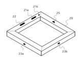
- the main body (housing) of the step information receiving unit 20 according to this embodiment has a rectangular frame structure, and includes a power switch 21a, an operation switch 22, and a sensor 23. , has a direction indication 25.
- the power switch 21a is a switch for switching power ON/OFF.
- 21b is an LED lamp that indicates the ON/OFF state of the power supply. Lights up when the power is turned on, and goes out when the power is turned off.
- the step information receiving unit 20 has a driving power source (not shown) supplied by a dry battery type or a rechargeable battery.
- the operation switch 22 is an operation switch for changing modes and making various settings.
- the direction display 25 is, for example, a display indicating the forward (F: front) direction.
- the player places the step information receiving unit 20 on the ground with the direction indicated by the direction display 25 facing forward.
- the sensor 23 is, for example, an infrared sensor, a phototransistor, an ultrasonic sensor, an optical sensor, a motion sensor, a laser, a CCD sensor, etc., within the sensing area to detect an object, a signal from the step information transmission unit 30, or an object. sensor device.
- At least one or more sensors 23 shown in FIG. 23c and 23d are provided, and in the signal detection mode, the sensor 23 detects a step detection signal transmitted from the step information transmission unit 30, such as light, as a step, and in the object detection mode , when the foot enters the sensing area of the step information receiving unit 20, it is detected as a step.
- a step detection signal transmitted from the step information transmission unit 30, such as light, as a step and in the object detection mode , when the foot enters the sensing area of the step information receiving unit 20, it is detected as a step.
- a plurality of sensors may be provided for each outer periphery depending on the type of sensor and detection accuracy.
- FIG. 5 is a diagram showing a functional configuration example of the step information transmitting unit 30 according to this embodiment.
- the step information transmission unit 30 according to this embodiment has a control section 30a, a sensor section 30b, and a detection signal transmission section 30c as main functional sections.
- the control section 30a controls the overall operation of the step information transmission unit 30 including the sensor section 30b and the detection signal transmission section 30c.
- the sensor unit 30b measures the acceleration, vibration, or impact that occurs when the player takes a step and the foot touches the ground.
- a step detection signal, such as light, is transmitted from the signal transmission unit 30c.
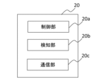
- FIG. 6 is a diagram showing a functional configuration example of the step information receiving unit 20 according to this embodiment.
- the step information receiving unit 20 according to this embodiment has a control section 20a, a detection section 20b, and a communication section 20c as main functional sections.
- the control section 20a controls the overall operation of the step information receiving unit 20 including the detection section 20b and the communication section 20c.
- the detection section 20b detects a step detection signal, such as light, transmitted by the step information transmission unit 30 worn on the player's foot.
- the communication unit 20c receives a step detection signal transmitted from the step information transmission unit 30 attached to the player's foot by the detection unit 20b.
- the detection information is transmitted to the game device 10 via the network 40.
- FIG. In the object detection mode, when the foot enters the sensing area of the sensor 23, the detection unit 20b detects it as a step, and the step detection information including the detection result and the position of the step detection area is sent to the communication unit 20c via the network 40. and transmit it to the game device 10.
- step information receiving unit 20 and the step information transmitting unit 30 are configured by the functional configurations described above. It is implemented by a control program executed on hardware resources such as a CPU, ROM, and RAM of a computer. Also, these functional units may be read as “means”, “module”, “unit”, or “circuit”.
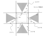
- FIG. 7 is a diagram showing, by hatching, the sensing areas of the respective sensors on the horizontal plane when the step information receiving unit 20 according to the present embodiment is viewed from above.
- FIG. 8 is a diagram showing the sensing area in the vertical plane of the sensor by hatching.
- the sensing area is an area that detects a step detection signal, such as light, when a player steps in the sensing area in the signal detection mode. In the object detection mode, when a foot enters the sensing area, it is detected as a step.
- the sensing area generally tends to spread out, from the outer perimeter where the sensor is installed to the outside, and there are cases where the sensing area has a wide response angle (for example, 60 degrees) as shown in Figure 7-a, and in Figure 7-b It may have a sensing area with a narrow response angle (for example, 20 degrees) shown in . These sensing areas can be adjusted by the type of sensor, the mechanism around the sensor, and the parts to be attached.
- the sensor 23a has an area B (back), the sensor 23b has an area R (right), the sensor 23c has an area F (front), and the sensor 23d has an area L (left). Therefore, in the signal detection mode, when the player lands on area B and steps, when the sensor 23a detects a step detection signal, such as light, transmitted from the step information transmission unit 30, it is detected as a step. When the player lands on the area R and steps, when the sensor 23b detects a step detection signal, for example light, transmitted from the step information transmission unit 30, it is detected as a step.
- a step detection signal such as light
- the step information receiving unit 20 desirably has each side of 27 cm or more and 30 cm or less, for example, in consideration of the stride length of a general person.
- the central part (hollow part) of the step information receiving unit 20 is a space-saving space, and a space sufficient for the player to stand up is not secured. Therefore, the player must stand in the sensing area of the step information receiving unit 20 before starting the game. By linking with game software, even if the player is standing in the sensing area, it can be prevented from being detected as a step until the game starts.
- the invention in the above-mentioned patent document installs a sensor on the outer periphery of a polygonal housing, and when the player's foot is detected in the sensing area of the sensor, it is detected as a step.
- the sensor tends to diffuse in the sensing area, and the degree of diffusion increases as the distance from the sensor increases.
- the detection method according to the above patent document even if the sensitivity of the sensor is adjusted, there is a tendency that even when the player's foot is not in contact with the floor surface or the ground, it is detected as a step. Therefore, even though the foot is not in contact with the floor surface or the ground, the sensor detects that the user is stepping, resulting in a problem that the accuracy of step detection cannot be improved.
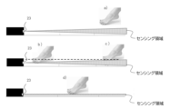
- FIG. 8 is a side view of the sensing area in the vertical direction to explain the problem of step detection accuracy in Patent Documents 2 and 3.
- the sensing area is indicated by hatching.
- the foot position is above the diffused sensing area. In this position no step is detected.
- b) and c) are areas where step detection begins when the foot touches the sensing area.
- the sensing area is spread out, when the player steps near the sensor (b) and when the player steps away from the sensor (c), the step detection height is different, c) , it is detected as a step at a position higher than the ground.
- FIG. 9 is a diagram showing an example of a game screen according to this embodiment.
- an arrow object pointing in any direction, up, down, left, or right, or a plurality of arrow objects will flow on the game screen, so that the player can make sure that the arrow object overlaps the step zone (judgment position) 10a. Take a step corresponding to the direction indicated at the appropriate timing.
- an arrow object pointing to the right is shown in the step zone 10a.
- Fig. 7-a An explanation will be given by taking Fig. 7-a as an example.
- the player steps in the sensing area R of the sensor 23b, and the sensor 23b detects a step detection signal, such as light, transmitted from the step information transmission unit 30 worn on the player's foot.
- the step information receiving unit 20 transmits step detection information including the detection result of the step detection signal and the position (for example, area R) where the step detection signal was detected to the game device 10 via the network 40 .
- the player takes a step in the sensing area R of the sensor 23b, and when the player's foot enters the sensing area, it is detected as a step, and the detection result of detecting the step and the detected position ( For example, step detection information including area R) is transmitted to the game device 10 via the network 40 .
- the game device 10 receives the step detection information from the step information receiving unit 20, the direction of the arrow object indicated in the step zone 10a on the game screen (for example, area R) and the step detection obtained from the step information receiving unit 20 are displayed.
- the step detection signal which is information, is compared with the step position information (for example, area R), and if they match, the step direction is determined to be correct. On the other hand, if they do not match, the step direction is determined to be incorrect.
- the step timing is determined to be correct. On the other hand, if the step is not detected within the predetermined time, the step timing is determined to be incorrect.
- the game device 10 adds points when the step direction and step timing are determined to be correct. Also, an indication indicating success (for example, "GREAT!) is displayed on the game screen.
- the step information receiving unit 20 is operated by a driving power source supplied by a dry battery, a rechargeable battery, or the like.
- the power control of the sensor 23 is an important factor for extending the battery life in order to suppress the power consumption of the sensor 23 .
- the step information receiving unit 20 (control section 20a) turns on the power of each sensor 23 in synchronization with the timing at which the game arrow object overlaps the step zone 10a, and when step detection is not required, Control to turn off the power of each sensor 23 is executed.
- the battery life of the step information receiving unit 20 is lengthened, the player can play the game for a long time, and the attractiveness of the step detection unit is improved.
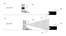
- FIG. 10 is a side view of a step detection signal transmitted by the step information transmitting unit 30 and the step information receiving unit 20 receiving the step detection signal in the signal detection mode.
- the signal transmitted by the step information transmitting unit 30 will be explained using the light of an LED as an example.
- the LED of the step information transmission unit 30 when the player's step (foot) is not in contact with the ground (e), the LED of the step information transmission unit 30 is not lit. As shown in f), when the step information transmission unit 30 detects the acceleration or vibration corresponding to the step due to the impact when the player takes a step and the foot lands on the floor surface or the ground, the step information The LED of the transmission unit 30 lights up and transmits a light signal. When the sensor 23 detects the signal, it detects that a step has been stepped on in an area corresponding to the sensing area of the sensor 23 .
- the step detection signal transmitted from the step information transmission unit 30 is higher than the installation position of the sensor 23 . Therefore, it is preferable to set the installation angle of the sensor 23 and the surrounding mechanism to an angle and a mechanism that can detect a step signal that is transmitted when the player touches the ground. This is because the step detection signal of the step information transmission unit 30 can be detected more reliably.
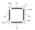
- FIG. 11 is a diagram in which color light emitting elements 20LED are provided on one side of each frame of the step information receiving unit 20 for the purpose of enhancing the realism of the game. For example, if the user steps in a position corresponding to the direction of the arrow object at the timing when it overlaps with the arrow object on the game screen, the light emitting element 20LED can be lit up to make the game more realistic.
- the element 20LED must be structured so as not to cause an error in the step detection sensitivity of each sensor. Also, when you step on the steps at the above timing, you can further enhance the presence by preparing not only the lighting effect of the color LED but also the sound effect.
- FIG. 12 is a plan view showing a modified configuration example of the game system according to the modified example described in FIG.
- a game system 100 of FIG. 12 includes a game device 10, a step information receiving unit 20 and a step information transmitting unit 30, and is connected to the game device 10 via a network 40. Compared with FIG. is arranged in the central (hollow) space of the step information receiving unit 20 .
- the player plays the game while facing the direction of the step information receiving unit 20 placed on the ground, that is, facing downward.
- players can practice their steps while checking their own steps, so it is expected that, for example, beginners who are not used to it will have less fear of falling and will be able to improve their steps even further. can.
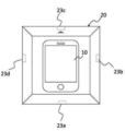
- FIG. 13 is a diagram showing the arrangement of the detection information notification unit 28 in the central spatial space of the step information reception unit 20.
- the detection information notification unit 28 is a terminal for notifying the step detection information including the detection result of the step detection signal of each sensor on the outer periphery of the step information reception unit 20 and the step detection area.
- the step detection information including the detection result and the detection position is converted to visible information, such as lighting of the light emitting element or It is a terminal that notifies by digital display or invisible information such as radio waves.
- the notification method of the detection information notification unit 28 shown in FIG. 13 will be described in detail, taking as an example the case where notification is given by lighting of a light emitting element.
- the light-emitting element 23dL lights up.
- the player steps in area B which has a sensing area that extends around the sensor 23a of the step information receiving unit 20, and detects the step
- the light-emitting element 23aL lights up.
- the player steps in area R which has a sensing area that extends around the sensor 23b of the step information receiving unit 20, and the step is detected
- the light-emitting element 23bL lights up.
- the player takes a step in area F which has a sensing area that extends around the sensor 23c of the step information receiving unit 20, and detects the step
- Notification by lighting of the light-emitting element can be changed to digital display.
- L (Left) for notification by 23dL light emitting element B (Back) for notification by 23aL light emitting element
- F (Front) for notification by 23cL light emitting element etc.
- any visible information such as QR code (registered trademark) can be used.
- the visible information notified from the detection information notification unit 28 is monitored by a camera attached to a smart device such as a smartphone, tablet, or game terminal in which a specially developed image recognition application or software is installed, Using the communication function of the smart device, the step detection information acquired from the detection information notification unit 28 can be sent to the game device 10 via the network 40 .
- the notification from the detection information notification unit 28 is transmitted as invisible information
- the step detection information is transmitted to the smart device by, for example, NFC or other wireless communication, and the invisible information is transmitted by an application or software installed in the smart device.
- Step detection information obtained from the detection information notification unit 28 can be sent to the game device 10 via the network 40 using the communication function of the smart device.
- the detection information notifying unit 28 eliminates the need to incorporate a communication module for transmitting information to the network 40 in the step information receiving unit 20, thereby reducing the cost of parts and the price of products.
- the detection of the notification signal of the detection information notification unit 28 is monitored by the rear camera of the smart device, and the game screen is displayed by turning the display section of the smart device upward to display the game device 10 in the center of the step information reception unit 20. Instead, the player can play while watching the game screen in the center of the step information receiving unit 20.
- FIG. 14 is a cross-sectional view of the step information receiving unit 20 according to this modification.
- the step information receiving unit 20 of FIG. 14 has a configuration in which the corners of each side are inclined compared to the above embodiments (for example, FIGS. 3 and 7).
- FIGS. 3 and 7 When the player steps on a step, there is a possibility that the player's foot accidentally touches the corner of the step information receiving unit 20, and the foot may be broken. It is possible to reduce the risk of injury.
- FIG. 15 is a diagram showing the sensing area viewed from the plane direction by the step information receiving unit 20 according to this modification.
- the step information receiving unit 20 according to this modification has an octagonal frame structure.
- At least one or more sensors 23 are provided on each of the eight sides of the outer periphery (outer edge) of the step information receiving unit 20, and the step information receiving unit 20 includes at least eight sensors 23a, 23b, and 23c. , 23d, 23e, 23f, 23g and 23h are provided.
- Each sensor 23, as indicated by the hatched area in FIG. 15, is directed outward from the outer perimeter where it is installed, and signals or It has a foot sensing area.
- the sensor 23e has an area BR
- the sensor 23f has an area RF
- the sensor 23g has an area FL
- the sensor 23h has an area LB. Therefore, in the signal detection mode, when the player lands on the area BR and steps, the sensor 23e detects a step detection signal, such as light, from the step information transmission unit 30.
- the sensor 23f detects a step detection signal, such as light, from the step information transmission unit 30.
- the sensor 23g detects a step detection signal, such as light, from the step information transmission unit 30.
- the sensor 23h detects a step detection signal from the step information transmission unit 30, such as light.
- the object detection mode when a foot enters the sensing area of the area, it is detected as a step.
- a step detection signal including the detection result of the step detection signal and position information (for example, area RF) where the step was detected is transmitted to the game device 10 via the network 40 .
- FIG. 16 is a diagram showing an example of a game screen in which steps are taken in eight directions according to this modification.
- an arrow object pointing in any direction on the game screen up, down, left, right, or diagonally (lower right, upper right, upper left, lower left) or a plurality of arrow objects will flow.
- the player takes a step corresponding to the indicated direction when the arrow object overlaps the step zone (judgment position) 10a.
- step zone 10a judgment position
- an arrow object pointing to the upper right direction is shown in the step zone 10a.
- the player firmly steps in the area RF corresponding to the upper right direction at the timing when the arrow object overlaps the step zone 10a.
- the step information receiving unit 20 is not limited to a rectangular frame structure, and may have, for example, a polygonal frame structure.
- a polygonal frame structure In addition to rectangular (quadrilateral) and octagonal shapes, for example, triangular and hexagonal shapes may also be used.
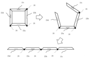
- FIG. 17 shows the step information receiving unit 20 with a structure in which each side of the step information receiving unit 20 is formed independently, and the connecting portions of the sides are connected by parts or contacts, for example, hinges 26 . It has a structure that can be changed from a square like 3 to any shape such as a straight line shape or an L shape. As a result, the structure is such that it can be deformed not only into a linear shape but also into various shapes starting from the parts or contacts, such as the hinges 26, at the connecting portions of each side.
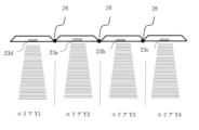
- FIG. 18 is a diagram showing a state of the step information receiving unit 20 having the shape of FIG. 17 when viewed from the plane when it is deformed with the hinge 26 as a starting point and developed on a straight line. In comparison with FIGS. 3, 7 and 15, in FIG. 18, the frame structure is straight.
- FIG. 19 shows the sensing area when the step information receiving unit 20 is linearly deformed. It is necessary to consider sensing areas where the hatched sensing areas do not interfere with detection in adjacent areas.
- the sensor 23d detects a step detection signal from the step information transmission unit 30, such as light.
- sensor 23a detects the step.
- sensor 23b detects the step.
- sensor 23c detects the step.
- the number of sensors and the number of sides can be provided according to the contents of the game. This enables detection of deformation in horizontal and vertical directions and in any shape possible with this structure. For example, it can be formed in an L shape. Being able to change the shape has the advantage of increasing the types of games that can be played, and the convenience of being able to be folded and stored in a desk drawer and convenient to carry.
- FIG. 20 is a side view of the sensor 23 with the lens 50 attached.
- the diffusion of the sensing area can be converged in the vertical direction, and the sensing area can be formed in a nearly linear shape when viewed from the side.
- g) is the state where the foot is above the sensing area and no step is detected
- h) is the state where the foot enters the sensing area and the step is detected.
- step detection can be performed by the step information receiving unit 20 alone without the step information transmitting unit 30 being required. Since step detection is performed when the foot enters the sensing area, it is desirable to install the sensor 23 at a position close to the ground. It becomes almost the same timing, and accurate step detection can be performed.
- the step detection accuracy is improved by attaching a lens to the sensor 23 according to the present embodiment, and the step information receiving unit 20 has a structure that can change its shape, making it possible to handle step games in various shapes.
- a game system that allows you to take steps anywhere, such as at home or on the go, creates opportunities to move your body more easily while having fun, and improves physical and mental health by moving your body casually. You can make products that contribute to Dance games are expected to have social benefits that lead to the promotion of people's health.
- the area (eg area R) and the horizontal sensing region (eg sensing region R) may not always match completely. be. That is, even if the step is in an area (for example, area R), if a step is performed in a non-detection region that is not a horizontal sensing region (for example, sensing region R), the step is not detected.
- the step information receiving unit 20 has each side of, for example, 27 cm or more and 30 cm or less in consideration of portability. Therefore, the non-detection area is extremely small and does not interfere with actual game play.
- the reaction angle of the sensor 23 is set large, the non-detection area becomes small, and if the reaction angle of the sensor 23 is set small, the non-detection area becomes large.
- the step information receiving units are arranged in a straight line, if the reaction angle of the sensor 23 is set too large, the sensing area will spread to other areas, and an erroneous detection will occur in which steps are detected in two areas. . Therefore, it is desirable to set the response angle of the sensor 23 so that the sensing area does not spread to other areas and the non-detection area is minimized.
- the body of the step information receiving unit 20 described above has been described as having a rectangular frame structure. However, it is not necessarily a frame (frame) structure, and may be, for example, a circular or polygonal board (plate) structure. In this case, the center of the step information receiving unit 20 does not have a cavity, but the sensor 23 is provided on each side. In addition to being able to arrange the game device 10 near the center of the step detection receiving unit 20 on the board, the game device 10 can be attached to the main body of the step information receiving unit 20 near the center of the board. It is also possible to provide a mechanism.
- the signal detection mode and the object detection mode are produced and commercialized in a configuration in which one of the modes is selected depending on the contents of the game. Both modes may exist in one device if desired.
Landscapes
- Engineering & Computer Science (AREA)
- Multimedia (AREA)
- Human Computer Interaction (AREA)
- Theoretical Computer Science (AREA)
- General Engineering & Computer Science (AREA)
- General Health & Medical Sciences (AREA)
- Computer Networks & Wireless Communication (AREA)
- Health & Medical Sciences (AREA)
- Life Sciences & Earth Sciences (AREA)
- Biophysics (AREA)
- Cardiology (AREA)
- Heart & Thoracic Surgery (AREA)
- General Physics & Mathematics (AREA)
- Physics & Mathematics (AREA)
- Position Input By Displaying (AREA)
- User Interface Of Digital Computer (AREA)
- Toys (AREA)
Abstract
Description
図1は、本実施形態に係るゲームシステムの構成例を示す図である。図1のゲームシステム100は、ゲーム装置10及びステップ情報受信ユニット20及びステップ情報発信ユニット30を含み、ネットワーク40を介して接続される。
図2は本実施形態に係るステップ情報発信ユニット30の図を示す。プレイヤーの足に装着するユニット・デバイスで、両足に個別に装着する。このため、一人のプレイヤーに2セット必要となる。
図3は、本実施形態に係るステップ情報受信ユニット20の配置例を示す。図4は、本実施形態に係るステップ情報受信ユニット20の平面図を示す。図3、4に示されるように、本実施形態に係るステップ情報受信ユニット20の本体(筐体)は、矩形形状のフレーム(枠)構造であって、電源スイッチ21a、操作スイッチ22、センサー23、方向表示25を有する。
図5は、本実施形態に係るステップ情報発信ユニット30の機能構成例を示す図である。図5に示されるように本実施形態にかかわるステップ情報発信ユニット30は、主な機能部として、制御部30a、センサー部30b、検知信号発信部30cを有する。
図7は、本実施形態に係るステップ情報受信ユニット20を平面から見た各センサーの水平面におけるセンシング領域をハッチングで示している図である。図8は前記センサーの垂直面でのセンシング領域をハッチングで示している図である。前記センシング領域は、信号検知モードではプレイヤーが前記センシング領域内でステップを踏んだ際にステップ検知信号、例えば光を検知する領域である。物体検知モードでは、足が前記センシング領域に入った際にステップとして検知する領域である。センシング領域は一般的に拡散する傾向があり、センサーが設置された外周辺から外側に向かい、図7-aに示す広い反応角度(例えば60度)でセンシング領域を有する場合や、図7-bに示す狭い反応角度(例えば20度)のセンシング領域を持つ場合もある。これらのセンシング領域はセンサーの種類やセンサー周辺の機構及び装着する部品により調整が可能である。
図9は、本実施形態に係るゲーム画面の一例を示す図である。
図11は、ゲームの臨場感を高める事を目的として、ステップ情報受信ユニット20の各フレームの一辺に、カラーの発光素子20LEDを装備した図である。例えば、ゲーム画面の当該矢印オブジェに重なっているタイミングでユーザーが矢印オブジェの方向に相応する位置でステップを踏んだ場合、発光素子20LEDを点灯させるなどゲームの臨場感を盛り上げることができる、この発光素子20LEDは、各センサーのステップ検知の感度に誤差を生じないような構造にする必要がある。また、上記タイミングでステップを踏んだ際には、カラーLEDのライティング効果のみならず、効果音を用意することにより、さらに臨場感を高めることができる。
図12は、図1で説明した、本変形例に係るゲームシステムを変形した構成例を示す平面図である。図12のゲームシステム100は、ゲーム装置10及びステップ情報受信ユニット20とステップ情報発信ユニット30を含み、ネットワーク40を経由してゲーム装置10と接続されるが、図1と比較すると、ゲーム装置10がステップ情報受信ユニット20の中心部(空洞部)のスペースに配置されている。
図13は、ステップ情報受信ユニット20の中心部の空間スペースに、検知情報通知ユニット28を配置した図である。この検知情報通知ユニット28は、ステップ情報受信ユニット20の外周部にある各センサーのステップ検知信号の検知結果とステップ検知エリアを含む、ステップ検知情報を通知する端末でケーブル27によりステップ情報受信ユニット20と電気的に接合していて、ステップ情報受信ユニット20の各センシング領域においてステップ検知信号が検知された場合に、その検知結果と検知位置を含むステップ検知情報を可視情報、例えば発光素子の点灯もしくはデジタル表示または不可視の情報例えば電波などで通知する端末である。
図14は、本変形例に係るステップ情報受信ユニット20の断面図である。図14のステップ情報受信ユニット20は、上記実施形態(例えば図3、図7)と比較すると、各辺の角に傾斜を持たせた構成である。プレイヤーがステップを踏むときに間違って足がステップ情報受信ユニット20本体の角に接触した時に足をくじく可能性があるが、これを回避する為、角に傾斜を持たせることで、ゲーム中の怪我を起こすリスクを低減することが可能である。また、センサー23がその水平面における位置より上位置より発信する信号を受け取りやすくなり、信号検知モードにおいてはセンサーの検知精度が高まる効果が期待できる。
図15は、本変形例に係るステップ情報受信ユニット20による平面方向から見たセンシング領域を示す図である。図7と比較すると、本変形に係るステップ情報受信ユニット20は、8角形状のフレーム(枠)構造となっている。また、センサー23は、ステップ情報受信ユニット20の外周辺(外縁)の8辺の各々に少なくとも1つ以上が設けられており、ステップ情報受信ユニット20としては少なくとも計8つのセンサー23a、23b、23c、23d、23e、23f、23g及び23hが設けられている。
図17は、ステップ情報受信ユニット20の各辺が独立して形成されており、前記各辺の連結部を部品もしくは接点、例えばヒンジ26により連結されている構造で、ステップ情報受信ユニット20を図3のような四角形から一直線形状やL字形状など任意の形状に変更ができる構造になっている。これにより一直線状の形状のみならず各辺の接続部にある部品もしくは接点例えばヒンジ26を起点として様々な形状に変形させることができる構造となっている。
10a 矢印オブジェがステップゾーン(判定位置)に重なっている状態
20 ステップ情報受信ユニット
20a 制御部
20b 検知部
20c 通信部
20LED LED
21a 電源スイッチ
21b 電源のON/OFFの状態を示すLEDランプ
22 操作スイッチ
23(a~h) ステップ情報受信ユニットのセンサー
23aL センサー23aでステップが検知された際に点灯する発光素子
23bL センサー23bでステップが検知された際に点灯する発光素子
23cL センサー23cでステップが検知された際に点灯する発光素子
23dL センサー23dでステップが検知された際に点灯する発光素子
25 方向表示
26 ヒンジ
27 ケーブル
28 検知情報通知ユニット
30 ステップ情報発信ユニット
30a 制御部
30b センサー部
30c 検知信号発信部
31 ステップ情報発信ユニットのベルト
32 ステップ情報発信ユニットの信号発信素子
33 ステップ情報発信ユニットのモジュール
40 ネットワーク
50 レンズ
100 ゲームシステム
エリアF 前方のエリア
エリアL 左側のエリア
エリアR 右側のエリア
エリアB 後ろ側のエリア
エリアRF 斜め右上のエリア
エリアFL 斜め左上のエリア
エリアBR 斜め右下のエリア
エリアLB 斜め左下のエリア
エリアY1 左から1番目のエリア
エリアY2 左から2番目のエリア
エリアY3 左から3番目のエリア
エリアY4 左から4番目のエリア
センシング領域 センサー23のセンシング領域
センシング領域R 右側のエリアにあるセンサー23のセンシング領域
a)足が拡散したセンシング領域の上にある状態
b)足がセンサーの近くで拡散したセンシング領域に接している状態
c)足がセンサーの遠くで拡散したセンシング領域に接している状態
d)最も下限に設置した非拡散センシング領域に足が接している状態
e)ステップ情報発信ユニットがステップ検知信号を発信していない状態
f)ステップ情報発信ユニットがステップ検知信号を発信している状態
g) ステップを検知していない状態
h)ステップを検知している状態
Claims (4)
- プレイヤーの両足に個別にステップ情報発信ユニット30を装着し、プレイヤーがステップを踏み、足が床面もしくは地面に接地した際に発生する加速度もしくは振動もしくは衝撃を、ステップ情報発信ユニット30に組み込まれているセンサー例えば加速度センサーで計測し、その計測結果がステップに相応するレベルにあった場合、ステップ検知信号、例えば光を発信するステップ情報発信ユニット30と、床面もしくは地面に配置された、多角形状の筐体の外周部の各辺に、一つ以上設けられた各センサーから一定範囲に広がる空間を検知するセンシング領域を有するステップ情報受信ユニット20で構成され、プレイヤーが前記センシング領域に対応するエリアでステップを踏むと、プレイヤーの足に装着している、ステップ情報発信ユニット30が前記ステップ検知信号を発信し、ステップ情報受信ユニット20の外周にあるセンシング領域内で前記ステップ検知信号を検知した際にプレイヤーがステップを踏んだものとして検知し、ステップ検知信号の検知結果とステップ検知エリアの位置を含むステップ検知情報を、ユニットに組み込まれている通信機能によりネットワーク40を経由してゲーム装置10に送信する通信手段を有するステップ検知ユニット。
- ステップ情報受信ユニット20の外周部の各辺に設けられているセンサー23によるステップ検知信号の検知結果と前記センサーのセンシング領域に対応する検知エリアの位置を含むステップ検知情報を、前記ステップ情報受信ユニット20と電気的に接続されたケーブルで繋がっている端末である検知情報通知ユニット28で可視情報、例えば発光素子、またはデジタル表示もしくは不可視情報たとえば電波で通知し、可視情報での通知の場合においては、前記可視情報をスマートデバイスに付属しているカメラで監視し、スマートデバイスにインストールされている専用アプリケーションまたはソフトで画像認識を行い、前記検知情報通知ユニット28より通知されたステップ検知情報を、前記スマートデバイスが持つ通信機能を使いネットワーク40を経由して、ゲーム装置10へ情報を送る、また不可視情報例えば電波での通知の場合、ステップ検知情報を前記不可視情報でスマートデバイスへ送りスマートデバイスにインストールされている専用アプリケーションまたはソフトで認識を行い、前記検知情報通知ユニットより通知された、ステップ検知情報を、前記スマートデバイスが持つ通信機能を使いネットワーク40を経由してゲーム装置10へ情報を送る、請求項1に記載のステップ検知ユニット。
- ステップ情報受信ユニット20の各辺が、独立したパーツで構成されており、前記各辺のパーツの連結部を部品もしくは接点、例えばヒンジにより連結されている構造で、一直線形状やL字形状など任意の形状に変形できる構造を持ち、一直線上に形状変更した際には、他のエリアのセンシング領域と干渉しないセンシング領域で構成された前記ステップ情報受信ユニットを有する、請求項1または請求項2に記載のステップ検知ユニット。
- ステップ情報受信ユニット20の外周部の各辺に設けられている各センサーにレンズを装着することによりセンシング領域を垂直方向において収束させ、プレイヤーがステップを踏むエリア内において横から見て直線状に近いセンシング領域を形成し、廉価な部品で精度の高いステップ検知を得ることが出来る請求項1ないし請求項2または請求項3に記載のステップ検知ユニット
Priority Applications (3)
| Application Number | Priority Date | Filing Date | Title |
|---|---|---|---|
| EP22883418.0A EP4389246A4 (en) | 2021-02-15 | 2022-10-11 | Step detection unit |
| CN202280066126.1A CN118119436A (zh) | 2021-02-15 | 2022-10-11 | 脚步检测单元 |
| US18/575,547 US20240374991A1 (en) | 2021-02-15 | 2022-10-11 | Step detection unit |
Applications Claiming Priority (3)
| Application Number | Priority Date | Filing Date | Title |
|---|---|---|---|
| JP2021064468 | 2021-02-15 | ||
| JP2021-170642 | 2021-10-19 | ||
| JP2021170642A JP7336495B2 (ja) | 2021-02-15 | 2021-10-19 | ステップ検知ユニット |
Publications (1)
| Publication Number | Publication Date |
|---|---|
| WO2023068114A1 true WO2023068114A1 (ja) | 2023-04-27 |
Family
ID=82941447
Family Applications (1)
| Application Number | Title | Priority Date | Filing Date |
|---|---|---|---|
| PCT/JP2022/037906 Ceased WO2023068114A1 (ja) | 2021-02-15 | 2022-10-11 | ステップ検知ユニット |
Country Status (5)
| Country | Link |
|---|---|
| US (1) | US20240374991A1 (ja) |
| EP (1) | EP4389246A4 (ja) |
| JP (1) | JP7336495B2 (ja) |
| CN (1) | CN118119436A (ja) |
| WO (1) | WO2023068114A1 (ja) |
Families Citing this family (1)
| Publication number | Priority date | Publication date | Assignee | Title |
|---|---|---|---|---|
| US20250222364A1 (en) * | 2024-01-10 | 2025-07-10 | Brittni Weston | Handheld video game console mounting method and assembly thereof |
Citations (13)
| Publication number | Priority date | Publication date | Assignee | Title |
|---|---|---|---|---|
| JPH07208944A (ja) * | 1994-01-26 | 1995-08-11 | Sumitomo Metal Mining Co Ltd | 狭間用物体検知センサ |
| JP2002165912A (ja) * | 2000-12-05 | 2002-06-11 | Konami Co Ltd | ダンスゲーム用コントローラ |
| JP3815938B2 (ja) | 2000-02-24 | 2006-08-30 | 株式会社バンダイナムコゲームス | ゲーム装置および情報記憶媒体 |
| JP2006247258A (ja) * | 2005-03-14 | 2006-09-21 | Konami Sports & Life Co Ltd | 動き情報処理システム |
| JP2006346323A (ja) * | 2005-06-20 | 2006-12-28 | Sanyo Electric Co Ltd | 運動靴 |
| JP2007125251A (ja) * | 2005-11-04 | 2007-05-24 | Konami Sports & Life Co Ltd | 動き情報処理システム、該システムに使用される端末装置、及び該端末装置の充電装置 |
| WO2007077851A1 (ja) * | 2005-12-30 | 2007-07-12 | Ssd Company Limited | 演出方法及び操作物 |
| JP2007275422A (ja) * | 2006-04-10 | 2007-10-25 | Aruze Corp | 床設置型フラットパネルディスプレイ装置を用いたゲーム装置 |
| US20080004111A1 (en) | 2006-06-30 | 2008-01-03 | Logitech Europe S.A. | Non Impact Video Game Controller for Dancing Games |
| US20080039199A1 (en) | 2006-08-03 | 2008-02-14 | Baer Ralph H | Object detection for an interactive human interface device |
| WO2008061023A2 (en) * | 2006-11-10 | 2008-05-22 | Mtv Networks | Electronic game that detects and incorporates a user's foot movement |
| JP2012520493A (ja) * | 2009-01-05 | 2012-09-06 | モベア エス.アー | 動作を特徴付ける装置と方法 |
| JP2020044353A (ja) * | 2019-11-22 | 2020-03-26 | 株式会社コナミアミューズメント | ゲーム機、及びコンピュータプログラム |
Family Cites Families (6)
| Publication number | Priority date | Publication date | Assignee | Title |
|---|---|---|---|---|
| US6001017A (en) * | 1993-08-25 | 1999-12-14 | Sega Enterprises, Ltd. | Game device for displaying game input operations on the display |
| US5913727A (en) * | 1995-06-02 | 1999-06-22 | Ahdoot; Ned | Interactive movement and contact simulation game |
| JP2006034323A (ja) | 2004-07-22 | 2006-02-09 | Woo Young Medical Co Ltd | 薬液定量自動注入装置及びその注入制御方法 |
| WO2006098299A1 (ja) * | 2005-03-14 | 2006-09-21 | Ssd Company Limited | 情報処理システム及びそのための情報入力装置 |
| US9776084B2 (en) * | 2015-06-15 | 2017-10-03 | Oculus Vr, Llc | Virtual reality system with camera shock-mounted to head-mounted display |
| JP7453490B2 (ja) * | 2019-01-21 | 2024-03-21 | 株式会社アルファコード | ユーザ属性推定装置およびユーザ属性推定方法 |
-
2021
- 2021-10-19 JP JP2021170642A patent/JP7336495B2/ja active Active
-
2022
- 2022-10-11 EP EP22883418.0A patent/EP4389246A4/en active Pending
- 2022-10-11 US US18/575,547 patent/US20240374991A1/en active Pending
- 2022-10-11 WO PCT/JP2022/037906 patent/WO2023068114A1/ja not_active Ceased
- 2022-10-11 CN CN202280066126.1A patent/CN118119436A/zh active Pending
Patent Citations (13)
| Publication number | Priority date | Publication date | Assignee | Title |
|---|---|---|---|---|
| JPH07208944A (ja) * | 1994-01-26 | 1995-08-11 | Sumitomo Metal Mining Co Ltd | 狭間用物体検知センサ |
| JP3815938B2 (ja) | 2000-02-24 | 2006-08-30 | 株式会社バンダイナムコゲームス | ゲーム装置および情報記憶媒体 |
| JP2002165912A (ja) * | 2000-12-05 | 2002-06-11 | Konami Co Ltd | ダンスゲーム用コントローラ |
| JP2006247258A (ja) * | 2005-03-14 | 2006-09-21 | Konami Sports & Life Co Ltd | 動き情報処理システム |
| JP2006346323A (ja) * | 2005-06-20 | 2006-12-28 | Sanyo Electric Co Ltd | 運動靴 |
| JP2007125251A (ja) * | 2005-11-04 | 2007-05-24 | Konami Sports & Life Co Ltd | 動き情報処理システム、該システムに使用される端末装置、及び該端末装置の充電装置 |
| WO2007077851A1 (ja) * | 2005-12-30 | 2007-07-12 | Ssd Company Limited | 演出方法及び操作物 |
| JP2007275422A (ja) * | 2006-04-10 | 2007-10-25 | Aruze Corp | 床設置型フラットパネルディスプレイ装置を用いたゲーム装置 |
| US20080004111A1 (en) | 2006-06-30 | 2008-01-03 | Logitech Europe S.A. | Non Impact Video Game Controller for Dancing Games |
| US20080039199A1 (en) | 2006-08-03 | 2008-02-14 | Baer Ralph H | Object detection for an interactive human interface device |
| WO2008061023A2 (en) * | 2006-11-10 | 2008-05-22 | Mtv Networks | Electronic game that detects and incorporates a user's foot movement |
| JP2012520493A (ja) * | 2009-01-05 | 2012-09-06 | モベア エス.アー | 動作を特徴付ける装置と方法 |
| JP2020044353A (ja) * | 2019-11-22 | 2020-03-26 | 株式会社コナミアミューズメント | ゲーム機、及びコンピュータプログラム |
Non-Patent Citations (1)
| Title |
|---|
| See also references of EP4389246A4 |
Also Published As
| Publication number | Publication date |
|---|---|
| EP4389246A4 (en) | 2025-06-25 |
| JP7336495B2 (ja) | 2023-08-31 |
| US20240374991A1 (en) | 2024-11-14 |
| EP4389246A1 (en) | 2024-06-26 |
| JP2022124453A (ja) | 2022-08-25 |
| CN118119436A (zh) | 2024-05-31 |
Similar Documents
| Publication | Publication Date | Title |
|---|---|---|
| JP5161182B2 (ja) | 情報処理プログラム及び情報処理装置 | |
| AU2020318880B2 (en) | An interactive apparatus | |
| JP5080196B2 (ja) | プログラム、情報処理装置、情報処理システムおよび情報処理方法 | |
| JP5689705B2 (ja) | 情報処理システム、情報処理プログラム、情報処理装置、入力装置、および情報処理方法 | |
| US11439898B2 (en) | Game controller | |
| US8079251B2 (en) | Computer readable storage medium storing information processing program and information processing apparatus | |
| JP5436909B2 (ja) | 情報処理プログラム、情報処理装置、情報処理システム、および、情報処理方法 | |
| JP5427346B2 (ja) | 荷重検出プログラム、荷重検出装置、荷重検出システムおよび荷重検出方法 | |
| US20180071621A1 (en) | Gaming System, Kit, and Method for Enabling Interactive Play | |
| CN106061307A (zh) | 鞋、声音输出系统以及输出控制方法 | |
| JP5456358B2 (ja) | 情報処理プログラムおよび情報処理装置 | |
| JP7336495B2 (ja) | ステップ検知ユニット | |
| US20080039199A1 (en) | Object detection for an interactive human interface device | |
| US20100041454A1 (en) | Portable dance game system | |
| US8337307B2 (en) | Computer-readable storage medium having stored therein music performance program, music performance apparatus, music performance method, and music performance system | |
| CN220495493U (zh) | 竞技装置 | |
| TWI813343B (zh) | 光學辨識控制型互動式玩具及光學辨識控制輸出方法 | |
| CN117173942A (zh) | 光电式互动玩教具及控制系统 | |
| KR20190066182A (ko) | 컴퓨터 마우스 | |
| KR20170059120A (ko) | 스텝퍼용 게임 컨트롤러 및 그 조립체 |
Legal Events
| Date | Code | Title | Description |
|---|---|---|---|
| 121 | Ep: the epo has been informed by wipo that ep was designated in this application |
Ref document number: 22883418 Country of ref document: EP Kind code of ref document: A1 |
|
| WWE | Wipo information: entry into national phase |
Ref document number: 202417010692 Country of ref document: IN |
|
| WWE | Wipo information: entry into national phase |
Ref document number: 2022883418 Country of ref document: EP |
|
| ENP | Entry into the national phase |
Ref document number: 2022883418 Country of ref document: EP Effective date: 20240223 |
|
| WWE | Wipo information: entry into national phase |
Ref document number: 18575547 Country of ref document: US |
|
| WWE | Wipo information: entry into national phase |
Ref document number: 202280066126.1 Country of ref document: CN |
|
| NENP | Non-entry into the national phase |
Ref country code: DE |