WO2023068144A1 - 組立式容器 - Google Patents
組立式容器 Download PDFInfo
- Publication number
- WO2023068144A1 WO2023068144A1 PCT/JP2022/038086 JP2022038086W WO2023068144A1 WO 2023068144 A1 WO2023068144 A1 WO 2023068144A1 JP 2022038086 W JP2022038086 W JP 2022038086W WO 2023068144 A1 WO2023068144 A1 WO 2023068144A1
- Authority
- WO
- WIPO (PCT)
- Prior art keywords
- connector
- water stop
- main body
- collapsible container
- leg
- Prior art date
- Legal status (The legal status is an assumption and is not a legal conclusion. Google has not performed a legal analysis and makes no representation as to the accuracy of the status listed.)
- Ceased
Links
Images




Classifications
-
- A—HUMAN NECESSITIES
- A47—FURNITURE; DOMESTIC ARTICLES OR APPLIANCES; COFFEE MILLS; SPICE MILLS; SUCTION CLEANERS IN GENERAL
- A47G—HOUSEHOLD OR TABLE EQUIPMENT
- A47G19/00—Table service
- A47G19/22—Drinking vessels or saucers used for table service
- A47G19/2205—Drinking glasses or vessels
- A47G19/2255—Details related to the connection between the liquid containing part and the supporting part
-
- A—HUMAN NECESSITIES
- A45—HAND OR TRAVELLING ARTICLES
- A45F—TRAVELLING OR CAMP EQUIPMENT: SACKS OR PACKS CARRIED ON THE BODY
- A45F3/00—Travelling or camp articles; Sacks or packs carried on the body
- A45F3/16—Water-bottles; Mess-tins; Cups
-
- A—HUMAN NECESSITIES
- A47—FURNITURE; DOMESTIC ARTICLES OR APPLIANCES; COFFEE MILLS; SPICE MILLS; SUCTION CLEANERS IN GENERAL
- A47G—HOUSEHOLD OR TABLE EQUIPMENT
- A47G19/00—Table service
- A47G19/22—Drinking vessels or saucers used for table service
- A47G19/2205—Drinking glasses or vessels
-
- A—HUMAN NECESSITIES
- A47—FURNITURE; DOMESTIC ARTICLES OR APPLIANCES; COFFEE MILLS; SPICE MILLS; SUCTION CLEANERS IN GENERAL
- A47G—HOUSEHOLD OR TABLE EQUIPMENT
- A47G19/00—Table service
- A47G19/22—Drinking vessels or saucers used for table service
- A47G19/23—Drinking vessels or saucers used for table service of stackable type
-
- B—PERFORMING OPERATIONS; TRANSPORTING
- B65—CONVEYING; PACKING; STORING; HANDLING THIN OR FILAMENTARY MATERIAL
- B65D—CONTAINERS FOR STORAGE OR TRANSPORT OF ARTICLES OR MATERIALS, e.g. BAGS, BARRELS, BOTTLES, BOXES, CANS, CARTONS, CRATES, DRUMS, JARS, TANKS, HOPPERS, FORWARDING CONTAINERS; ACCESSORIES, CLOSURES, OR FITTINGS THEREFOR; PACKAGING ELEMENTS; PACKAGES
- B65D11/00—Containers having bodies formed by interconnecting or uniting two or more rigid, or substantially rigid, components made wholly or mainly of plastics material
- B65D11/02—Containers having bodies formed by interconnecting or uniting two or more rigid, or substantially rigid, components made wholly or mainly of plastics material of curved cross-section
- B65D11/04—Bottles or similar containers with necks or like restricted apertures designed for pouring contents
-
- B—PERFORMING OPERATIONS; TRANSPORTING
- B65—CONVEYING; PACKING; STORING; HANDLING THIN OR FILAMENTARY MATERIAL
- B65D—CONTAINERS FOR STORAGE OR TRANSPORT OF ARTICLES OR MATERIALS, e.g. BAGS, BARRELS, BOTTLES, BOXES, CANS, CARTONS, CRATES, DRUMS, JARS, TANKS, HOPPERS, FORWARDING CONTAINERS; ACCESSORIES, CLOSURES, OR FITTINGS THEREFOR; PACKAGING ELEMENTS; PACKAGES
- B65D13/00—Containers having bodies formed by interconnecting two or more rigid, or substantially rigid, components made wholly or mainly of the same material, other than metal, plastics, wood or substitutes therefor
- B65D13/02—Containers having bodies formed by interconnecting two or more rigid, or substantially rigid, components made wholly or mainly of the same material, other than metal, plastics, wood or substitutes therefor of glass, pottery, or other ceramic material
Definitions
- the present invention relates to a collapsible container.
- Containers such as wine glasses are generally made of glass, and are therefore fragile and must be handled with care. Also, the ball portion for pouring the liquid and the plate portion for supporting the container are integrally formed.
- Patent Literature 1 Japanese Patent Publication No. 2015-500697 discloses a wine glass that is easy to carry. In order to facilitate portability, this wine glass is detachable using magnets from a container into which wine can be poured and drunk, and a stem to which a plate is connected. , the stem can be housed in the housing.
- a ball portion for pouring liquid, a plate portion for supporting a container, and a stem connecting the ball portion and the plate portion are integrally formed. Therefore, a certain amount of space is required to accommodate the container. Moreover, handling is not easy when carrying. Further, in the wine glass disclosed in Patent Document 1, the ball portion and the stem are detachable, and the detached stem can be stored in the storage portion (ball portion) using a magnet. is stated. However, even in this wine glass, since the storage portion has a certain volume, it is necessary to secure a certain amount of space even when the stem portion is stored in the storage portion. Moreover, the stem portion and the storage portion (ball portion) that are detached and stored by the magnet easily fall off due to vibration. Therefore, it is not easy to handle only the ball portion and the stem portion, which are the constituent members.
- the object of the present invention is to provide a container whose bowl part can be disassembled and assembled, and whose constituent members do not fall off even when transported.
- a collapsible container comprises an upper body portion having a first connector portion and a lower body portion having a second connector portion coupled to the first connector portion of the upper body portion.
- the upper body portion and the lower body portion are configured to be assembled and/or disassembled using the first connector portion and the second connector portion.
- the first connector portion has a projection or a recess formed on the outer periphery of the upper body portion
- the second connector portion is formed on the inner periphery of the lower body portion and has a projection or recess on the first connector portion.
- It has a concave portion or a convex portion formed so as to be fittable with the convex portion, and is configured so that the concave and convex portions of the first connector portion and the second connector portion are fitted. Further, when the first connector portion and the second connector portion are coupled, the bottom surface portion of the first connector portion and the bottom surface portion of the second connector portion are arranged to face each other. Furthermore, it is characterized by having a leak prevention part for preventing liquid from leaking by connecting the first connector part and the second connector part.
- a collapsible container includes an upper body portion having a first connector portion, and a lower body portion having a second connector portion coupled to the first connector portion of the upper body portion.
- the lower body portion is configured to be assembled and/or disassembled using the first connector portion and the second connector portion. Therefore, by pouring a liquid such as wine into the collapsible container, a predetermined liquid can be accommodated in the collapsible container. Furthermore, when the collapsible container is carried or stored on a shelf or the like, the upper and lower main bodies can be separated, so that it can be easily carried and stored without taking up space. .
- the bottom surface portion of the first connector portion and the bottom surface portion of the second connector portion are arranged to face each other.
- a leakage preventing portion for preventing leakage of liquid is provided between the first connector portion and the second connector portion. Therefore, even when the collapsible container is tilted, it is possible to prevent the liquid from leaking out of the collapsible container from the connecting portion between the upper body portion and the lower body portion.
- the collapsible container according to the present invention may be characterized in that a gap is formed between the convex portion and the concave portion, and the gap functions as a leakage prevention portion.
- a gap is formed between the convex portion and the concave portion, and the gap blocks the flow of the liquid and can hold the liquid. Leakage to the outside from between the surface portion and the inner peripheral surface portion of the second connector can be effectively prevented.
- collapsible container according to claim 2 wherein the collapsible container according to claim 2 is configured such that the inner peripheral side of the lower main body part becomes larger in the downward direction from the upper side. .
- the concave portion increases downward from the upper side of the inner peripheral side of the lower body portion.
- the gap between the concave portion on the inner peripheral side of the lower body portion and the convex portion on the upper body portion is also positioned below the second connector portion. , a larger amount of liquid can be stored in the gap.
- the bottom portion of the first connector portion has a first water stop portion having a convex or concave shape
- the bottom portion of the second connector portion has the first water stop portion.
- the convex or concave shape of the second water stop portion has a tapered shape whose width decreases toward the distal direction, and the bottom surface portion of the first connector portion and the bottom surface portion of the second connector portion face each other.
- the first water stop portion and the second water stop portion may be arranged to face each other and function as the leakage prevention portion when the first water stop portion and the second water stop portion are arranged so as to face each other.
- the bottom portion of the first connector portion has the first water stop portion
- the bottom portion of the second connector portion has the second water stop portion.
- the shape of the second water stop portion has a tapered shape in which the width becomes smaller toward the tip.
- the length of the gap between the water parts is elongated compared to when it is provided substantially vertically, and when the liquid is poured into the collapsible container and tilted, the movement of the liquid to the outside of the gap is effectively reduced. can be done.
- the second water stop portion and the first water stop portion face each other to form a contact portion, thereby blocking the gap and preventing the liquid from leaking out of the knockdown container from the gap. , can be effectively prevented.
- the second water stop portion has a recessed water storage portion, and the water storage portion has the first water stop portion and the second water stop portion facing each other.
- a space for holding liquid is formed in the water storage portion when the liquid storage portion is arranged, and functions as a leakage prevention portion.
- the collapsible container even if liquid exists between the first water-stopping portion and the second water-stopping portion of the assembled collapsible container, the first water-stopping portion and the second water-stopping portion When the parts are arranged to face each other, a space is formed in the water storage part, which can effectively prevent the movement and leakage of the liquid to the outside of the knockdown container due to the occurrence of capillary action. Also, by standing the collapsible container, the liquid can move downward in the space and be stored in the reservoir.
- the bottom portion of the second connector portion may have a sloped surface that slopes downward toward the inside in the radial direction.
- the bottom portion is formed so as to be inclined downward toward the inside in the radial direction, so that when the first connector portion and the second connector portion are assembled, the first connector portion
- the amount of liquid that flows out to the outside of the gap when the liquid is poured into the collapsible container and tilted by stretching the space between the bottom face and the bottom face of the second connector part compared to when the bottom face is formed substantially horizontally can be effectively reduced.
- the inclined surface is inclined upward against the movement of the liquid radially outward of the gap compared to when the gap is formed substantially horizontally. can be effectively prevented from leaking out of the gap.
- the liquid when liquid is present in the gap, by standing the collapsible container, the liquid can move radially inward of the gap along the inclined surface and return to the liquid storage section.
- the bottom portion of the second connector portion has a stepped portion extending in the circumferential direction
- the bottom portion of the first connector portion has a stepped portion extending in the circumferential direction
- the first connector portion and the second connector have a stepped portion extending in the circumferential direction.
- the stepped portion extending in the circumferential direction is formed on the bottom surface portion of the second connector portion. Even if liquid enters a small gap between the bottom surface of the connector part and the bottom surface of the first connector part, the stepped part of the bottom part of the second connector part acts as a wall, and the liquid is prevented from entering the gap or outside. can prevent leakage to Further, the stepped portion provided on the bottom surface of the second connector and the stepped portion provided on the bottom surface of the first connector face each other and partially abut on each other, thereby forming a wall portion. The wall can block the flow of liquid out of the collapsible container.
- the upper main body can be separated from the lower main body and stored in the lower main body, and when the upper main body is stored in the lower main body, the first connector is inserted through the opening of the lower main body in a state where the upper and lower parts are turned upside down, and the protrusions or recesses of the first connector part are fitted into the protrusions or recesses of the second connector part,
- the upper body portion may be configured to be fixedly coupled to the lower body portion.
- the upper main body can be separated from the lower main body and stored in the lower main body. upside down and inserted through the opening of the lower main body to store the upper main body in the lower main body, thereby reducing the required storage space.
- the protrusions or recesses of the first connector section are configured to be fitted into the protrusions or recesses of the second connector section, the first connector section and the second connector section are fixed, It can be fixed to the lower body part and the upper body part.
- the lower body portion has leg receiving portions on the outer peripheral bottom surface portion, and further includes legs detachably provided on the leg receiving portions of the lower body portion, and the legs are provided at the lower portion. It is configured so that it can be separated from the main body and stored in the lower main body.
- the leg has a stem portion for attachment to and detachment from the lower body portion, and a plate portion connected to the stem portion.
- the collapsible container according to the present invention further comprises a leg detachably provided on the leg receiving portion of the lower main body, the leg comprising a stem for attaching to and detaching from the lower main body, and a stem attached to the stem. and a connected plate portion.
- the legs When storing the legs in the lower main body, the legs are inserted through the openings of the lower main body with the legs turned upside down to reduce the required storage space. Further, since the projections or recesses provided on the plate portion of the leg are configured to fit into the projections or recesses of the second connector portion, the leg can be fixed to the lower main body.
- the leg portion has a projection-shaped second connecting portion on the bottom surface side of the plate portion.
- the lower main body can be connected in multiple stages by connecting the second connection part of the leg to the leg receiving part of the lower main body. good too.
- the legs have the projection-shaped second connecting portions on the bottom surface side of the plate portion. It can be connected to the leg receiving part of the lower body part, and the lower body part can be connected in multiple stages, so that it can be stacked vertically and the storage space in the cupboard, rucksack, etc. can be reduced. can do
- the collapsible container according to the present invention may be characterized in that the upper body part is configured to be able to be connected to the lower body part in multiple stages while being housed in the lower body part.
- the upper main body part is accommodated in the lower main body part, and the lower main body part can be connected in multiple stages, so that the upper main body part, the lower main body part, and the leg parts can be combined. It is structured so that it can be connected in multiple stages in a consolidated form, and the storage space in a cupboard, rucksack, etc. can be reduced.
- a collapsible container includes an upper body portion having a first connector portion, and a lower body portion having a second connector portion coupled to the first connector portion of the upper body portion. Since the lower body part can be assembled and/or disassembled using the first connector part and the second connector part, when pouring a liquid such as wine into the collapsible container, the upper body part and A predetermined liquid can be accommodated by coupling with the lower body portion. Furthermore, when the collapsible container is carried or stored on a shelf or the like, the upper body part and the lower body part can be separated, so that the container can be easily carried or stored without taking up space.
- the bottom surface portion of the first connector portion and the bottom surface portion of the second connector portion are arranged to face each other, and the liquid It is characterized by having a leakage prevention part for preventing the leakage of the liquid.
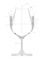
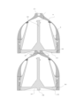
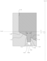
- FIG. 1 is a diagram for schematically explaining the assembly type container according to the first embodiment. Moreover, it is a figure which shows the perspective view of a container roughly.
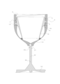
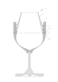
- FIG. 2 is a diagram schematically showing a cross-sectional view of the collapsible container when the collapsible container according to the first embodiment is assembled.
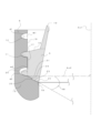
- FIG. 3 is an enlarged schematic view of part A in FIG.
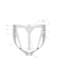
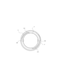
- FIG. 4 is a top view schematically showing the lower body portion of the assembly type container according to the first embodiment.
- FIG. 5 is a diagram for schematically explaining a state in which the knockdown container according to the first embodiment is disassembled and the upper main body portion is accommodated in the lower main body portion.
- FIG. 1 is a diagram for schematically explaining the assembly type container according to the first embodiment. Moreover, it is a figure which shows the perspective view of a container roughly.
- FIG. 2 is a diagram schematically showing a cross-sectional view of the collapsible container when the collapsible container according to
- FIG. 6 is a diagram for schematically explaining a state in which the knockdown container according to the first embodiment is disassembled and the upper main body and legs are stored in the lower main body.
- FIG. 7 is a diagram for explaining a state in which the collapsible containers according to the first embodiment are stacked in two stages and stored.
- FIG. 8 is a diagram schematically showing a top view of the assembly type container according to the first embodiment.
- FIG. 9 is a diagram schematically showing a sectional view of the collapsible container when the collapsible container is assembled.
- FIG. 10 is a diagram for schematically explaining an assembly type container according to the second embodiment. Moreover, it is a figure which shows the perspective view of a container roughly.
- FIG. 10 is a diagram for schematically explaining a state in which the knockdown container according to the first embodiment is disassembled and the upper main body and legs are stored in the lower main body.
- FIG. 7 is a diagram for explaining a state in which the collapsible
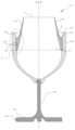
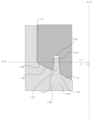
- FIG. 11 is a diagram schematically showing a cross-sectional view of the assembly-type container when the assembly-type container according to the second embodiment is assembled.
- FIG. 12 is a schematic enlarged view of the B portion of FIG. 11 .
- FIG. 13 is a schematic enlarged view of part C of FIG. 12 .
- FIG. 14 is a diagram schematically showing a cross-sectional view of the collapsible container when the collapsible container according to the second embodiment is assembled.
- the container according to this embodiment is a container that can be freely assembled, disassembled, and stored. First, the collapsible container 1 in an assembled state will be described in detail below.
- FIG. 1 is a diagram for schematically explaining a collapsible container 1 according to the first embodiment.
- FIG. 1 shows a perspective view of a collapsible container 1.
- FIG. 2 shows a cross-sectional view of the collapsible container 1 of FIG. 2 shows the central axis Ax1 of the collapsible container 1.
- FIG. 1 shows a perspective view of a collapsible container 1.
- FIG. 2 shows a cross-sectional view of the collapsible container 1 of FIG. 2 shows the central axis Ax1 of the collapsible container 1.
- FIG. 1 is a diagram for schematically explaining a collapsible container 1 according to the first embodiment.
- FIG. 1 shows a perspective view of a collapsible container 1.
- FIG. 2 shows a cross-sectional view of the collapsible container 1 of FIG. 2 shows the central axis Ax1 of the collapsible container 1.
- FIG. 1 shows a
- the knockdown container 1 can include a container main body 2 and legs 30 that are arranged in order in the extending direction of the central axis Ax1.
- the container body 2 includes an upper body 3 having a first connector 5 and a lower body having a second connector 6 coupled to the first connector 5 of the upper body 3.
- a portion 4 may be provided.
- the upper main body portion 3 and the lower main body portion 4 of the container main body portion 2 are configured to be assembled and disassembled using the first connector portion 5 and the second connector portion 6 .
- first connector portion 5 of the upper body portion 3 and the second connector portion 6 of the lower body portion 4 are provided so as to be directly coupled without using a cushioning material such as packing.
- the upper body portion 3 of the collapsible container 1 has a substantially circular first opening 7 .
- a liquid 14 such as water, sake, wine, etc.
- the upper main body 3 and the lower main body 4 are combined to form the container main body 2, and the predetermined liquid is poured from the first opening 7. can be accommodated.
- the upper body portion 3 has a substantially circular second opening 8 on the side that is coupled to the lower body portion 4 .
- the upper body portion 3 can have, for example, a generally frusto-conical shape, with the second opening 8 having a larger diameter than the first opening 7 .
- the shape of the upper main body portion 3 is not limited to this, and can have, for example, a substantially cylindrical shape.
- the lower main body part 4 is provided so that the second connector part 6 is connected to the first connector part 5 of the upper main body part 3 so that it can be assembled, disassembled, and stored with the upper main body part 3 . Further, the lower body portion 4 can have a substantially circular third opening 9 on the side connected to the upper body portion 3 .
- the central axis Ax1 passes through substantially the center portions of the substantially circular first opening 7, second opening 8, and third opening 9. As shown in FIG. From the top of FIG. 2, the first opening 7, the third opening 9, and the second opening 8 are arranged in this order.
- the upper body portion 3, the lower body portion 4, and the leg portion 30, which constitute the collapsible container 1, are made of, for example, resins such as glass and plastic, stone materials such as ceramics, metals such as aluminum, copper, and stainless steel, or wood such as cedar. can become In this embodiment, the material of the upper body part 3, the lower body part 4 and the legs 30 is glass.
- the upper body portion 3 can have a tubular portion 10 and a first connector portion 5 .
- a first opening 7 is provided at one end of the cylindrical portion 10 .
- a first connector portion 5 is provided on the other end side of the tubular portion 10 .
- the first connector portion 5 can be fitted with the second connector portion 6 of the lower body portion 4 to attach the upper body portion 3 to the lower body portion 4 .
- the second opening 8 of the first connector portion 5 faces the lower main body portion 4 side and is provided so as to abut at least partially.
- first connector portion 5 can have a first coupling protrusion 11 formed on the outer periphery of the upper body portion 3 .
- second connector portion 6 is provided on its inner periphery with a coupling recess 12 that can be fitted to the first coupling projection 11 and the projections and recesses thereof.
- the first coupling protrusion 11 is formed in two spiral stages along the entire outer circumference of the first connector section 5, and is fitted into the coupling recess 12 of the second connector section 6. , can function as a so-called male screw.
- the lower body portion 4 coupled with the upper body portion 3 will be described.
- the lower body portion 4 can have a liquid storage portion 13 and a second connector portion 6 for fitting the first connector portion 5 of the upper body portion 3 .
- a third opening 9 is provided on one end side of the second connector portion 6 .
- a liquid storage portion 13 is provided on the other end side of the second connector portion 6 .
- the liquid storage portion 13 can store a liquid 14 such as water, sake, or wine poured from the first opening 7 in the bottom portion of the liquid storage portion 13 .
- the liquid storage portion 13 is provided in a bowl shape.
- the shape of the liquid storage portion 13 is not limited to the bowl shape, and may be, for example, a polyhedron such as an octahedron, or an oval shape.
- the second connector portion 6 of the lower body portion 4 has a coupling recess 12 on its inner periphery for fitting with the first coupling protrusion 11 of the first connector portion 5 .
- the connecting concave portion 12 can be formed along the entire inner circumference of the second connector portion 6 so as to fit the first connecting convex portion 11 , corresponding to the shape of the first connecting convex portion 11 . can.
- the coupling recess 12 is provided as a so-called female thread into which the first coupling protrusion 11 of the first connector portion 5 can be fitted.
- the upper body portion 3 is combined with the lower body portion 4 to form an integrated container, but on the other hand, it can also be separated from the lower body portion 4. is configured as The separated upper body portion 3 is configured to be housed in the lower body portion 4 .
- the upper body part 3 and the lower body part 4 can be separated, so that it can be easily stored without taking up space.
- the legs 30 detachably connected and fixed to the lower body portion 4 can also be separated from the lower body portion 4 . Further, the leg portion 30 is also configured to be housed in the lower body portion 4 in a state where the upper body portion 3 is housed in the lower body portion 4 .
- the coupling recesses 12 can be used for coupling and fixing the lower body portion 4 side.
- the groove length (step) of the coupling recess 12 is longer than the length of the first coupling protrusion 11 to be coupled. Too long.
- FIG. 3 is a schematic enlarged view of part A of FIG. Note that FIG. 3 shows a central axis Ax1 and a horizontal axis Ax2 perpendicular to the central axis Ax1.
- the first connector portion 5 As shown in FIG. 3 , the first connector portion 5 is provided below the tubular portion 10 of the upper body portion 3 .
- the first connector portion 5 has a first connector bottom surface portion 15 , a first connector top surface portion 16 and a first connector outer peripheral surface portion 17 .
- the first connector outer peripheral surface portion 17 is provided substantially parallel to the extending direction of the central axis Ax1.
- the first connector outer peripheral surface portion 17 is provided with the first coupling protrusion 11 that is continuously formed in a spiral shape.
- the first coupling protrusion 11 is a protrusion used for coupling with the second connector section 6 .
- the first coupling protrusion 11 is spirally provided on the outer peripheral surface of the first connector portion 5 over two turns (two stages).
- the shape of the first coupling projection 11 is not limited to this. , or may be provided in the shape of a plurality of islands.
- first connector bottom surface portion 15 which is the lower side of the first connector outer peripheral surface portion 17, is attached to the second connector bottom surface provided in the second connector portion 6 when the upper body portion 3 and the lower body portion 4 are assembled.
- portion 18 Corresponding to the shape of the portion 18, they are configured and arranged so as to face each other and at least partially abut.
- the first connector upper surface portion 16 which is the upper side of the first connector outer peripheral surface portion 17, separates the upper body portion 3 and the lower body portion 4 from each other, and when the upper body portion 3 is housed in the lower body portion 4, It faces the second connector bottom surface portion 18 of the lower main body portion 4 and is arranged so as to be able to abut at least partially.
- the collapsible container 1 is configured such that the upper body portion 3 can be separated from the lower body portion 4 and disassembled, and the upper body portion 3 can be stored in the lower body portion 4 .
- the first connector top face portion 16 and the second connector bottom face portion 18 face each other.
- at least a part of the first connector top surface portion 16 abuts on the second connector bottom surface portion 18 so that the upper body portion 3 can be stably accommodated in the lower body portion 4 .
- the second connector portion 6 has a second connector bottom surface portion 18 and a second connector inner peripheral surface portion 19 .
- the second connector inner peripheral surface portion 19 is formed on the first connector outer peripheral surface portion 17 so that it can face the first connector outer peripheral surface portion 17 when the first connector portion 5 and the second connector portion 6 are connected. It is provided corresponding to the shape.
- the second connector inner peripheral surface portion 19 corresponds to the first connector outer peripheral surface portion 17 and is provided substantially parallel to the extending direction of the central axis Ax1.
- the second connector inner peripheral surface portion 19 is provided with a coupling recess 12 configured to allow coupling of the first coupling projection 11 .
- the coupling recess 12 corresponds to the shape of the first coupling projection 11 and is spirally provided so that it can be fitted.
- the second connector bottom surface portion 18 extends from the lower side of the second connector inner peripheral surface portion 19 to the liquid storage portion 13 .
- the coupling recess 12 provided in the second connector inner peripheral surface portion 19 can be provided so that one end side thereof is positioned near the second connector bottom surface portion 18 .
- FIG. 3 a horizontal axis Ax2 orthogonal to the central axis Ax1 is shown, and the second connector bottom portion 18 of the second connector portion 6 is inclined downward by an angle ⁇ 1 with respect to the horizontal axis Ax2. It is
- This angle ⁇ 1 is the average of the angles formed by the second connector bottom surface 18 and the horizontal axis Ax2 provided over the entire circumference of the second connector bottom surface 18, and is, for example, in the range of 15 degrees to 60 degrees. be able to.
- the second connector bottom surface portion 18 is provided in a substantially planar shape.
- the shape of the second connector bottom portion 18 is not limited to this.
- a shape curved radially inward from the outer periphery, or a corrugated shape having repeated unevenness may be provided.
- the first connector portion 5 and the second connector portion 6 are formed with the first connector outer peripheral surface portion 17 and the second connector inner peripheral surface portion 19, and the first connector bottom surface portion 15.
- the second connector bottom surface portion 18 they are configured to face each other over the entire circumference and be able to abut at least partially.
- one end side of the first connector outer peripheral surface part 17 and the second connector inner peripheral surface part 19 facing each other is connected to the outside of the assembly type container 1, and the other end side is connected to the outside of the assembly type container 1. It is connected to the opposed portions of the first connector bottom surface portion 15 and the second connector bottom surface portion 18 . Furthermore, the other end side of the facing portion of the first connector bottom surface portion 15 and the second connector bottom surface portion 18 is connected to the liquid storage portion 13 .
- the collapsible container 1 is connected with the first connector part 6 and the second connector part 7 to prevent the liquid 14 from leaking out.
- a leak prevention part is provided.
- the first coupling protrusion 11 is provided as a protrusion that can be fitted into the coupling recess 12 .
- the shape of the protrusion of the first coupling protrusion 11 can be provided in substantially the same shape from the upper end to the lower end of the first coupling protrusion 11 .
- the second connector portion 6 of the lower body portion 4 is provided with a second connector inner peripheral surface portion 19 on its inner peripheral surface.
- Coupling recesses 12 are provided which correspond to the coupling protrusions 11 so that they can be fitted.
- the first connector bottom portion 15 of the first connector portion 5 and the second connector bottom portion 18 of the second connector portion 6 are arranged to face each other. Also, it is difficult to form the first connector outer peripheral surface portion 17 and the second connector inner peripheral surface portion 19 so as to be in contact with each other over the entire surface, and a slight gap is formed.
- the collapsible container 1 When drinking the liquid 14 from the collapsible container 1, the collapsible container 1 is tilted, and the liquid 14 flows through the gap between the first connector bottom surface portion 15 and the second connector bottom surface portion 18 and the first connector outer peripheral surface portion 17. It may reach the second connector inner peripheral surface portion 19 and leak to the outside.
- the liquid 14 can flow through the small gap between the first connector bottom portion 15 and the second connector bottom portion 18 and the first connector outer peripheral surface portion 17. Even if it reaches the facing portion of the second connector inner peripheral surface portion 19, the gap portion 20, which is the fitting portion between the first connecting convex portion 11 and the connecting concave portion 12 facing each other, blocks the flow of the advancing liquid 14, It can also be held. Therefore, the gap 20 functions as a leakage prevention part, and can prevent the liquid 14 from leaking out of the collapsible container 1 from between the first connector outer peripheral surface 17 and the second connector inner peripheral surface 19 .
- the first connector outer peripheral surface portion 17 and the second connector inner peripheral surface portion 19 and the second connector can be separated from each other by standing the assembly type container 1 upright.
- the liquid 14 remaining between the inner peripheral surfaces 19 descends along the gap 20 and can be accumulated at the bottom of the gap 20 .
- the liquid 14 accumulated at the bottom of the space 20 can be returned to the liquid storage section 13 by slightly loosening the connection between the container main body 2 and the upper main body 3 of the collapsible container 1 and tilting them.
- bonding convex part 11 is provided in convex shape.
- the first coupling protrusion 11 can also be provided in a concave shape.
- the first coupling projection 11 and the coupling recess 12 correspond to each other. 12 can also be fitted.
- the coupling recess 12 forming the space 20 is extended from the upper end of the second connector inner peripheral surface 19 near the third opening 9 to the second connector inner peripheral surface 19 near the liquid storage portion 13 .
- the concave portion can have a shape such that the depth in the radial direction and the width in the vertical direction gradually increase toward the lower end.
- the vertical width W of the coupling recess 12 can change from W1 to W2 having a larger value than W1 in the downward direction from the upper side of the coupling recess 12 .
- the radial depth d of the coupling recess 12 can change from d1 to d2, which has a value greater than d1, from the top to the bottom of the coupling recess 12 .
- the values of the width W and the depth d of the coupling recess 12 are configured to gradually change from the upper side of the coupling recess 12 toward the lower side. However, it is not necessary to gradually change the values of W and d of the coupling recess 12, and they may be provided so as to be changed stepwise.
- the size of the gap 20 also changes from the upper side to the lower side of the coupling recess 12. It is configured to gradually increase in size in the lateral direction.
- the gap portion 20 is larger on the lower side of the second connector portion 6, more of the liquid 14 that has entered between the first connector portion 5 and the second connector portion 6 can be accumulated in the bottom portion of the gap portion 20. can.
- the gap 20 is formed above the first coupling projection 11. It is
- the second connector bottom surface portion 18 of the second connector portion 6 can have an inclined surface 23 that is inclined radially inward and downward by an angle ⁇ 1 with respect to the horizontal axis Ax2. .
- the first connector bottom surface portion 15, which corresponds to the second connector bottom surface portion 18 and is provided so as to be able to abut on at least a part of the second connector bottom surface portion 18, is located on the second connector bottom surface portion 15 when the upper body portion 3 and the lower body portion 4 are assembled. 18 are arranged to face each other.
- first connector bottom surface portion 15 and the second connector bottom surface portion 18 are arranged to face each other while being inclined downward by an angle ⁇ 1 with respect to the horizontal axis Ax2.
- the second connector bottom surface 18 Since the second connector bottom surface 18 has an inclined surface 23 inclined downward by an angle ⁇ 1 with respect to the horizontal axis Ax2, when the liquid 14 is drunk, there is a gap between the first connector bottom surface 15 and the second connector bottom surface 18. Even if the liquid 14 enters a small gap, the sloped surface 23 of the second connector bottom surface 18 acts as a leak prevention section that resists the traveling direction of the liquid 14 and becomes an upward slope, 14 can be effectively prevented from entering the gap 20. ⁇
- the liquid 14 when the liquid 14 is accumulated in the gap 20 of the assembled collapsible container 1, by standing the collapsible container 1, the liquid 14 follows the downward slope of the inclined surface 23 and moves along the inclined surface 23. It can flow and return to the liquid storage section 13 .
- a second connector bottom surface stepped portion 22 is formed on the second connector bottom surface portion 18 .
- the second connector bottom surface step portion 22 will be described below.
- the second connector bottom surface stepped portion 22 is provided on the second connector bottom surface portion 18 as a depression (recess) extending in the circumferential direction of the second connector portion 6 .
- the second connector bottom surface stepped portion 22 is provided in the second connector bottom surface portion 18 in the form of a linear notch.
- the present invention is not limited to this, and the second connector bottom surface stepped portion 22 can be provided in a curved shape, for example.
- the size of the step of the second connector bottom surface step portion 22 can be, for example, about 0.1 mm or more and less than 3 mm.
- the second connector bottom surface stepped portion 22 is provided on the second connector bottom surface portion 18 , when the liquid 14 is drunk from the collapsible container 1 , there is a slight difference between the first connector bottom surface portion 15 and the second connector bottom surface portion 18 . Even if the liquid 14 enters the gap, the second connector bottom surface stepped portion 22 acts as a leakage prevention portion against the advancing direction of the liquid 14, and has an even steeper slope than the inclined surface 23, so that the liquid 14 flows into the gap portion 20. can effectively prevent intrusion into
- the first connector bottom surface portion 15 also has a first connector bottom surface step portion 21 corresponding to the second connector bottom surface step portion 22 provided on the inclined surface 23 of the second connector bottom surface portion 18 . is provided.
- the first connector bottom surface stepped portion 21 faces the second connector bottom surface stepped portion 22 and is provided so that at least a portion of the first connector bottom surface stepped portion 21 can come into contact with the second connector bottom surface stepped portion 22 .
- the second connector bottom surface stepped portion 22 of the second connector bottom surface portion 18 and the first connector bottom surface stepped portion 21 of the first connector bottom surface portion 15 face each other.
- a wall portion 24 can be formed at the facing portion between the first connector bottom surface stepped portion 21 and the second connector bottom surface stepped portion 22 .
- the wall portion 24 By forming the wall portion 24 at the opposing portion of the second connector bottom surface stepped portion 22 and the first connector bottom surface stepped portion 21 , it is possible to block the flow of the liquid 14 to the outside of the knockdown container 1 . Therefore, the wall portion 24 functions as a leakage prevention portion, effectively preventing the liquid 14 from passing through the gap between the first connector bottom portion 15 and the second connector bottom portion 18 to the outside of the knockdown container 1. can do.
- the second connector bottom surface stepped portion 22 is provided in one step on the second connector bottom surface portion 18 .
- the first connector bottom stepped portion 21 of the first connector bottom portion 15 is also provided in one step corresponding to the second connector bottom stepped portion 22 , and forms a wall portion 24 in one step facing each other.
- the wall portion 24 does not necessarily have to have a single step, and a plurality of wall portions 24 can be provided by providing a plurality of second connector bottom surface stepped portions 22 in the radial direction.
- the second connector bottom surface step portion 22 and the first connector bottom surface step portion 21 provide contact portions in multiple stages, effectively preventing the liquid 14 from entering the gap portion 20 . be able to.
- the second connector groove portion 25 is a groove-shaped concave portion provided in the second connector bottom surface portion 18 .
- the second connector groove portion 25 extends radially from the lower end of the coupling recess portion 12 to the end portion of the second connector bottom portion 18 .
- the collapsible container 1 can be erected.
- the liquid 14 descends through the second connector groove portion 25 according to the angle of the inclined surface 23 of the second connector bottom portion 18 and can automatically return to the liquid storage portion 13 .
- the upper body portion 3 of the collapsible container 1 is combined with the lower body portion 4 to form an integral container, but it is also configured so that it can be separated from the lower body portion 4 . Further, the leg portion 30 detachably connected and fixed to the lower body portion 4 can also be separated from the lower body portion 4 .
- the upper main body part 3 is configured to be separated from the lower main body part 4 and stored in the lower main body part 4 .
- the leg portion 30 is also configured to be housed in the lower body portion 4 in a state where the upper body portion 3 is housed in the lower body portion 4 .
- a state in which the upper body portion 3, the lower body portion 4 and the leg portions 30 of the collapsible container 1 are disassembled and the upper body portion 3 and the leg portions 30 are stored in the lower body portion 4 will be described.
- FIG. 5 is a diagram for explaining a state in which the upper body portion 3 is housed and fixed in the lower body portion 4. As shown in FIG. Moreover, in FIG. 5, the leg part 30 has shown the disassembled state.
- the first connector portion 5 when the upper main body portion 3 is housed in the lower main body portion 4, the first connector portion 5 is turned upside down, and the first connector portion 5 is inserted through the third opening 9 of the lower main body portion 4. As shown in FIG. By inserting and fitting the first coupling projection 11 of the first connector portion 5 into the coupling recess 12 of the second connector portion 6, the required storage space can be reduced.
- the first connector top surface portion 16 of the first connector portion 5 and the second connector bottom surface portion 18 of the upper main body portion 3 are opposed to each other and at least partially It is provided so as to be abuttable, and the upper body portion 3 can be stably accommodated in the lower body portion 4 .
- the first coupling projection 11 of the first connector portion 5 is configured to fit into the coupling recess 12 of the second connector portion 6, the first connector portion and the second connector portion are coupled.
- the upper body portion 3 can be fixed to the lower body portion 4 .
- a leg receiving portion 31 is provided at the lower outer periphery of the lower main body portion 4 to allow the leg portion 30 to be attached and detached.
- the leg receiving portion 31 is configured to have a concave shape.
- the leg portion 30 can have a stem portion 32 for attaching and detaching to the leg receiving portion 31 of the lower body portion 4 and a plate portion 34 connected to one end side of the stem portion 32 .
- a first connecting portion 33 is provided on the other end side of the stem portion 32 so as to correspond to and connect with the leg receiving portion 31 .
- the first connecting portion 33 is configured in a convex shape.
- the first connecting portion 33 can also be provided in a concave shape when the leg receiving portion 31 is provided in a convex shape.
- FIG. 6 shows a view in which the upper main body portion 3 and the leg portion 30 are accommodated in the lower main body portion 4.
- the leg portion 30 is stored in the lower main body portion 4, the leg portion 30 is turned upside down and inserted through the third opening 9 of the lower main body portion 4 for storage. Storage space can be reduced.
- the leg portion 30 has a plate portion 34 provided with a second coupling projection portion 35 .
- the second coupling protrusion 35 is a protrusion provided on the side surface of the plate section 34 , and the leg section 30 uses the second coupling protrusion 35 to provide coupling on the inner peripheral side of the second connector section 6 . It is provided so that it can be connected and fixed to the concave portion 12 .
- the second coupling protrusion 35 is provided in a convex shape.
- the second coupling protrusion 35 can also be provided in a concave shape when the coupling recess 12 is provided in a convex shape.
- the upper body portion 3 is housed in the lower body portion 4 while being fixed by screwing the first coupling protrusion 11 to the coupling recess 12 .
- the groove length (step) of the coupling recess 12 is longer than the coupling length of the first coupling protrusion 11, so that the coupling recess 12 of the second connector portion 6 is
- the second coupling projection 35 of the leg portion 30 can be further coupled while the first coupling projection 11 is screwed.
- the collapsible container 1 can stack and connect a plurality of collapsible containers 1 in a stored state in multiple stages.
- a projecting second connecting portion 36 is provided on the bottom surface side of the plate portion 34 of the leg portion 30 .
- the second connecting parts 36 are coupled to the leg receiving parts 31 of the lower main body 4, thereby connecting a plurality of containers in multiple stages.
- the second connecting portion 36 is provided in substantially the same shape as the first connecting portion 33 .
- the second connecting portion 36 is not limited to this, as long as it can be connected to the leg receiving portion 31, and can be provided in a convex shape, for example.
- a plate bottom portion 37 is provided in the vicinity of the second connecting portion 36 .
- the plate bottom portion 37 is provided so that at least a portion of the surface faces each other and can partially abut against each other as surfaces that face each other when the collapsible containers 1 are stacked and stored in multiple stages.
- the collapsible container 1 Since the collapsible container 1 has the plate bottom portion 37, when the accommodated collapsible container 1 is vertically stacked and combined, it can be stably loaded.
- the lower collapsible container 1 bears the weight of the stacked collapsible containers 1 .
- the lower body portion 4 and legs 30 will bear the weight.
- FIG. 8 is a top view of the collapsible container 1 in a state in which the upper body portion 3, the lower body portion 4, and the leg portion 30 are assembled.
- the liquid storage portion 13 can be provided with a stopper 38 for supporting the upper body portion 3 on the inner peripheral surface.
- two stoppers 38 are arranged in the liquid storage portion 13 in a convex shape.
- the collapsible container 1 has the stopper 38 , the weight applied to the lower body portion 4 and the leg portion 30 can be distributed to the upper body portion 3 .
- the collapsible container 1 since the collapsible container 1 uses screw connections when assembled and stored, twisting and rotating force is generated in each member. As shown in FIG. 8, the collapsible container 1 may have reinforcements 39 provided to accommodate rotational forces. In the present embodiment, two reinforcing portions 39 are provided on the outer side of the upper body portion 3 . However, the reinforcing portion 39 is not limited to this, and can be provided on the inner peripheral surface of the lower main body portion 4 and the leg portion 30, for example.
- the force applied when disassembling and assembling the upper main body part 3 and the lower main body part 4 can be dispersed and the breakage can be prevented.
- the collapsible container 101 is also a container that can be freely assembled, disassembled, and stored, like the collapsible container 1 described in the first embodiment.
- the collapsible container 101 in an assembled state will be described below.
- descriptions of parts having the same configuration as that of the collapsible container 1 may be omitted.
- FIG. 10 is a diagram for schematically explaining the assembly type container 101 according to the second embodiment.
- FIG. 10 shows a perspective view of the collapsible container 101.
- FIG. 11 shows a cross-sectional view of the collapsible container 101.
- the central axis Ax3 of the collapsible container 101 is shown in the figure.
- the collapsible container 101 can have a container main body 102 and legs 130 arranged in order in the vertical direction.
- the container main body 102 includes an upper main body 103 having a first connector 105 and a first connector of the upper main body 103, which are arranged in order in the extending direction of the central axis Ax3 axes.
- a lower body portion 104 having a second connector portion 106 coupled to 105 may be provided.
- the upper body portion 103 can have a tubular portion 10 and a first connector portion 105 for connecting with the lower body portion 104 .
- a first opening 7 is provided on the other end side of the cylindrical portion 10 .
- the first connector portion 105 can have a first joint portion 150 provided for fixing to the second connector portion 106 on its outer peripheral surface.
- the first joint portion 150 is a fixing portion provided on the outer peripheral surface of the first connector portion 105, and when the first connector portion 105 and the second connector portion 106 are coupled, the upper body portion 103 and the lower body portion 104 are joined together. It is provided to secure it and prevent it from falling off.
- the first joint portions 150 are provided in concave shapes at three locations on the outer peripheral surface of the first connector portion 105 .
- the first joint portion 150 joins the first connector portion 105 of the upper body portion 103 and the second connector portion 106 of the lower body portion 104 in the same manner as in the collapsible container 1 of the first embodiment. It is sufficient if it can be fixed and prevented from falling off.
- it can be provided in a convex shape on the outer peripheral surface of the first connector portion 105, or can be provided continuously over the entire circumference of the outer peripheral surface.
- the second connector portion 106 of the lower body portion 104 has a second joint portion 151 having a convex shape corresponding to the first joint portion 150 of the first connector portion 105 on the inner peripheral surface. ing.
- the second joint portion 151 is fitted into the first joint portion 150 when the first connector portion 105 of the upper body portion 103 is fixed to the second connector portion 106 of the lower body portion 104, whereby the upper body portion 103 and the lower body portion 104 are fixed to prevent them from coming off.
- the upper body portion 103 is formed so as to be fixed to the lower body portion 104 without falling off. ing.
- first connector portion 105 and the second connector portion 106 when the first connector portion 105 and the second connector portion 106 are coupled, the first connector portion 105 and the second connector portion 106 are directly coupled. A gap is formed between 105 and the second connector portion 106 (see FIG. 13).
- the lower body portion 104 will be described with reference to FIG. 2 again.
- the lower main body part 104 is provided with the third opening 9 in the upper part.
- the third opening 9 is in contact with one end of the second connector portion 106 .
- the second connector portion 106 of the lower body portion 104 can have a second joint portion 151 on the inner peripheral surface for joining with the first joint portion 150 of the first connector portion 105 .
- the second joint portion 151 corresponds to the shape of the first joint portion 150 and is formed on the inner peripheral surface of the second connector portion 106 .
- the disassembled upper main body part 103 is configured to be housed in the lower main body part 104, like the knockdown container 1 of the first embodiment.
- the lower body portion 104 is provided so as to accommodate the leg portion 130 while accommodating the upper body portion 103 .
- the leg portion 130 When the leg portion 130 is housed in the lower body portion 104, the inner peripheral side of the second connector portion 106 and the leg portion 130 face each other, and the third joint portion 160 provided on the second connector portion 106 is used.
- the lower main body portion 104 and the leg portion 130 can be fixed to each other to prevent them from coming off.
- the leg portion 130 is provided with a fourth joint portion 161 on the plate portion 134 .
- the fourth joint portion 161 is a convex portion provided on the side surface of the plate portion 134 , and the leg portion 130 uses the fourth joint portion 161 to form a third joint provided on the inner peripheral side of the second connector portion 106 . It is provided so that it can be connected and fixed to the portion 160 .
- the third joint portion 160 is provided in a concave shape and can be fitted with the fourth joint portion 161 of the leg portion 130 .
- the third joint portion 160 is not limited to this, and may be provided in a concave shape, for example, as long as the third joint portion 160 can be fixed when the leg portion 130 is housed in the lower body portion 104 and can be prevented from coming off.
- the fourth joint portion 161 of the leg portion 130 also corresponds to each other. For example, by providing a convex shape, the leg portion 130 is connected and fixed to the lower body portion 104 be able to.
- FIG. 12 is a cross-sectional view schematically showing an enlarged state of portion B shown in FIG. 11 .
- FIG. 13 also shows a central axis Ax3 and a horizontal axis Ax4 orthogonal to the central axis Ax3.
- 13 is a cross-sectional view schematically showing a state in which the B portion of FIG. 12 is enlarged.
- the first connector portion 105 will be described with reference to FIG. 12 .
- the first connector portion 105 is provided on the lower side of the tubular portion 10 of the upper body portion 103 .
- the first connector portion 105 can have a first connector outer peripheral surface portion 117 , a first connector bottom surface portion 115 and a first connector top surface portion 116 .
- the first connector outer peripheral surface portion 117 is connected to the first connector bottom surface portion 115 at its one end side, and connected to the first connector top surface portion 116 at its other end side. Further, the tubular portion 10 is provided on the upper portion of the first connector upper surface portion 116 . On the other hand, a second opening 8 is provided in the lower portion of the first connector bottom portion 115 .
- the second connector portion 106 As shown in FIG. 12, the second connector portion 106 is provided above the liquid storage portion 13 .
- the second connector portion 106 can have a second connector inner peripheral surface portion 119 and a second connector bottom surface portion 118 .
- the second connector inner peripheral surface portion 119 faces the first connector outer peripheral surface portion 117 of the upper main body portion 103 when the upper main body portion 103 and the lower main body portion 104 are coupled, and is provided so as to at least partially abut on the first connector outer peripheral surface portion 117 . It has a third opening 9 in the upper part and is connected to the second connector bottom part 118 in the lower part.
- one end side of the second connector bottom surface portion 118 is connected to the second connector inner peripheral surface portion 119 at the upper portion thereof.
- the liquid containing portion 13 is provided on the other end side of the second connector bottom portion 118 .
- the second connector bottom surface portion 118 is provided so as to face the first connector bottom surface portion 115 of the first connector portion 105 and at least partially abut on the first connector bottom surface portion 115 of the first connector portion 105 when the upper body portion 103 and the lower body portion 104 are assembled.
- the second connector bottom surface portion 118 can have a second water stop portion 153, which will be described in detail later.
- the second water stop portion 153 is provided in a concave shape over the entire circumference of the second connector bottom surface portion 118 .
- the second water stop portion 153 is provided so as to have a concave shape.
- the second water stop portion 153 is not limited to this, and may be provided to have a convex shape, for example. (See Fig. 14)
- the first connector bottom portion 115 can also have a first water stop portion 152 corresponding to the second water stop portion 153 .
- the first water stop portion 152 is provided over the entire circumference of the first connector bottom surface portion 115 and faces the second water stop portion 153 of the second connector bottom surface portion 118 so that at least a portion thereof can abut. is provided.
- the first water stop portion 152 and the second water stop portion 153 can face each other and at least partially contact each other.
- the first water stop portion 152 is provided in a convex shape corresponding to the second water stop portion 153 .
- the present invention is not limited to this, and it is sufficient that the first water stop portion 152 faces the second water stop portion 153 and can partially abut, for example, it can be provided so as to have a concave shape. (See Fig. 14)
- the first connector part 105 and the second connector part 106 are joined, and the first connector outer peripheral surface part 117 and the second connector inner peripheral surface part are joined.
- One end of the connector 119 is connected to the outside of the container main body 102 , and the other end is connected to the connecting portion between the first connector bottom portion 115 and the second connector bottom portion 118 .
- the other end side of the connecting portion of the first connector bottom surface portion 115 and the second connector bottom surface portion 118 is connected to the liquid storage portion 13 .
- first connector bottom surface portion 115 and the second connector bottom surface portion 118, and the first connector outer peripheral surface portion 117 and the second connector inner peripheral surface portion 119, which are connected and arranged, are formed so as to abut over the entire surface. can be difficult.
- a sealing member such as packing is not provided between the first connector portion 105 and the second connector portion 106, and the first connector portion 105 and the second connector portion 106 are directly connected. Therefore, when the first connector portion 105 and the second connector portion 106 are coupled, a gap portion 120 is formed between the first connector portion 105 and the second connector portion 106 .
- the collapsible container 101 When the collapsible container 101 is used to drink the liquid 14 , the collapsible container 101 is tilted, and the liquid 14 flows from the liquid storage portion 13 through the gap 120 between the first connector bottom portion 115 and the second connector bottom portion 118 to the second connector bottom portion 115 . It may reach the gap 120 between the outer peripheral surface 117 of the first connector and the inner peripheral surface 119 of the second connector, and then leak to the outside.
- the first connector bottom surface portion 115 and the second connector bottom surface portion 115 facing each other may
- the bottom surface portion 118 , the first connector outer peripheral surface portion 117 and the second connector inner peripheral surface portion 119 have leakage prevention portions, thereby blocking the flow of the liquid 14 and allowing the liquid 14 to flow from the gap 120 to the outside of the collapsible container 101 . can be prevented from leaking into the
- FIG. 13 shows the central axis Ax3 and the horizontal axis Ax4.
- the first connector bottom portion 115 can have the first water stop portion 152 having a convex or concave shape. Further, the second connector bottom surface portion 118 can have a second water stop portion 153 having an uneven shape corresponding to the shape of the first water stop portion 152 .
- the first water stop portion 152 and the second water stop portion 153 are configured to at least partially abut against each other when the first connector bottom portion 115 and the second connector bottom portion 118 are arranged to face each other. Department.
- the first water stop portion 152 and the second water stop portion 153 are provided so as to be fittable, and when the first connector portion 105 and the second connector portion 106 are coupled, the first water stop portion By fitting 152 into the second water stop portion 153 , the first water stop portion 152 is inserted into the second water stop portion 153 , and the outer peripheral surface of the first water stop portion 152 becomes the outer periphery of the second water stop portion 153 . It can face and at least partially abut the surface.
- a portion of the first water stop portion 152 and the second water stop portion 153 form an abutting portion, thereby blocking the void portion 120, and when the liquid 14 is poured into the knockdown container 101 and tilted, It is possible to effectively prevent the liquid 14 from leaking out of the collapsible container 101 through the gap 120 .
- the gap 120 between the first connector bottom surface portion 115 and the second connector bottom surface portion 118 is formed substantially horizontally. is stretched compared to
- the amount of the liquid 14 leaking from the gap 120 to the outside of the knockdown container 101 can be measured, for example, from the gap 120 to the pipeline. Since the length that receives the frictional resistance of is stretched, it can be effectively reduced.
- first water stop portion 152 and the second water stop portion 153 are provided with inclined tapered portions on the radially outer side surface and the inner side surface.
- the taper portions provided in the first water stop portion 152 and the second water stop portion 153 are formed so that the width thereof becomes smaller from the opening toward the distal direction.
- the radially outer peripheral side surface portion of the second water stop portion 153 is provided radially outwardly and upwardly at an angle ⁇ 2 with respect to the horizontal axis Ax4. , a second water cutoff outer peripheral tapered portion 154 .
- first water stop portion 152 can have a first water stop portion outer peripheral taper portion 155 on the side surface on the radially outer peripheral side.
- the side surface on the radially inner peripheral side of the second water stop portion 153 is provided in the second water stop portion provided radially inward and upward at an angle ⁇ 3 with respect to the horizontal axis Ax4. It may have a circumferential taper 156 .
- first water stop portion 152 can have a first water stop portion inner peripheral tapered portion 157 on the radially inner peripheral side surface.
- the first water stop portion 152 faces the second water stop portion 153 and is provided so as to be able to partially abut. Therefore, the first water stop outer peripheral tapered portion 155 and the second water stop outer peripheral tapered portion 154, and the first water stop portion 152 and the second water stop inner peripheral tapered portion 156 face each other and can partially abut each other. It is set up like this.
- the second water stop outer peripheral tapered portion 154 and the first water stop outer peripheral tapered portion 155 face each other at an angle of approximately ⁇ 2 with respect to the horizontal axis Ax4. , at least partially abuttable.
- the second water stop portion inner peripheral tapered portion 156 and the first water stop portion inner peripheral tapered portion 157 are also configured to face each other at an angle of approximately ⁇ 3 with respect to the horizontal axis Ax4 so that they can at least partially contact each other.
- the second water stop outer tapered portion 154 and the first water stop outer tapered portion 155 face each other at an angle of approximately ⁇ 2 from the horizontal axis Ax4, so that the second water stop outer tapered portion 154 and the first water stop outer tapered portion
- the gap 120 between the outer peripheral tapered portions 155 is also formed to be inclined.
- the second water stop inner peripheral tapered portion 156 and the first water stop inner peripheral tapered portion 157 face each other while being inclined substantially at an angle ⁇ 3 from the horizontal axis Ax4.
- the gap 120 between the water cutoff inner peripheral tapered portions 157 is also formed to be inclined.
- the space 120 is formed to be inclined, when the liquid 14 is poured into the collapsible container 101 and tilted, for example, the volume of the liquid 14 that can be held in the space 120 increases. The amount of liquid 14 that moves out of the formula container 101 can be effectively reduced.
- the second water stop portion outer peripheral tapered portion 154, the first water stop portion outer peripheral tapered portion 155, and the second water stop portion inner peripheral tapered portion 156 and the first waterproof portion inner peripheral tapered portion 157 can form a partial contact portion.
- the second water stop outer tapered portion 154 and the first water stop outer tapered portion 155, and the second water stop inner tapered portion 156 and the first water stop inner tapered portion 157 form contact portions. , the gap 120 can be blocked, and when the liquid 14 is poured into the knockdown container 101 and tilted, the liquid 14 can be effectively prevented from leaking out of the knockdown container 101 from the void 120. .
- the angle ⁇ 2 is the angle formed between the extending line of the second water stop outer peripheral tapered portion 154 and the horizontal axis Ax4 toward the radially inner side and downward, for example, "45 degrees ⁇ 2 ⁇ 90 degrees”. can be in the range of
- angle ⁇ 3 is an angle formed between the extending line of the second water stop inner peripheral tapered portion 156 and the horizontal axis Ax4 toward the radially outer side and downward. can be a range.
- the second water stop portion outer peripheral tapered portion 154 is provided along the entire circumference of the second water stop portion 153 on the radially outer peripheral side.
- the second water stop portion inner peripheral tapered portion 156 can be provided along the entire circumference of the second water stop portion 153 on the inner peripheral side in the radial direction.
- the second water stop portion outer peripheral tapered portion 154 and the second water stop portion inner peripheral tapered portion 156 can also be partially provided in the second water stop portion 153 .
- the second water stop portion outer peripheral tapered portion 154 is provided at the same angle over the entire circumference of the second water stop portion 153 .
- the second water stop portion inner circumference tapered portion 156 is also provided at the same angle over the entire circumference of the second water stop portion 153 .
- the second water stop portion outer peripheral tapered portion 154 and the second water stop portion inner peripheral tapered portion 156 can also be provided at, for example, a plurality of different angles in the second water stop portion 153 .
- the second water stop portion 153 will be described with reference to FIG. 13 again.
- the second water stop portion 153 can have a water reservoir portion 158 .
- the water storage portion 158 is a recessed leakage prevention portion provided in the second water stop portion 153 .
- the water storage portion 158 holds the liquid 14 between the first water stop portion 152 and the second water stop portion 153 when the first connector bottom portion 115 and the second connector bottom portion 118 are arranged to face each other. It is possible to form a space for
- the liquid 14 can flow downward in the void portion 120 by standing the assembly type container 101. It can be moved and stored in the reservoir 158 .
- the water storage portion 158 is provided at one location of the second water stop portion 153 .
- the water storage portion 158 can also be provided over the entire circumference of the second water stop portion 153, for example.
- the water storage portion 158 is provided as an extension of the concave portion of the second water stop portion 153 .
- the water storage portion 158 is not limited to this. When provided as a shape, it can also be provided as a shortened portion of the second water stop portion 153 . (See Fig. 14)
- the wine glass as a collapsible container has been described, but it is not limited to wine glasses, and can be used in cups used in general households and restaurants, containers for takeout, outdoors. It can be applied to a container that stores the liquid 14 inside, such as a portable water bottle.
- the method of connecting the first connector portion 105 and the second connector portion 106 is not limited to the above method, and other members such as elastic or frictional fixing, packing, and anti-slip may be used.
Landscapes
- Engineering & Computer Science (AREA)
- Mechanical Engineering (AREA)
- Rigid Containers With Two Or More Constituent Elements (AREA)
Abstract
Description
されている。このワイングラスでは、携帯が容易になるように、ワインを注いで飲むことができる収容部と、プレートが接続されたステムとを磁石を用いて着脱可能になっており、また、携帯するときは、ステムを収容部に収納することができる。
第1コネクタ部と第2コネクタ部を結合したときに、第1コネクタ底面部と第2コネクタ底面部の間に形成された空隙部は、略水平に形成されたときと比べ、延伸される。空隙部が延伸されることで、組立式容器に液体を注ぎ傾けたとき、空隙部から組立式容器の外部に流出する液体を効果的に減少させることができる。また、第1止水部と第2止水部が対向し配置されることで、空隙部を堰き止め、空隙部から、液体が組立式容器の外部へと漏出することを効果的に防止することができる。また、第2止水部の形状は、先端に行くほど、幅が小さくなるテーパー形状を有することで、第1コネクタ部と第2コネクタ部を組み立てたとき、第2止水部と第1止水部の間の空隙部の長さは、略垂直に設けたときと比べ、延伸され、組立式容器に液体を注ぎ傾けたとき、液体の空隙部外部への移動を効果的に減少させることができる。また、第2止水部と第1止水部が対向し、当接部が形成されることで、空隙部を堰き止め、空隙部から、液体が組立式容器の外部へと漏出することを、効果的に防止することができる。
前記第2コネクタ部の底面部は周方向に延伸する段差部を有し、前記第1コネクタ部の底面部は周方向に延伸する段差部を有し、前記第1コネクタ部と前記第2コネクタ部とが、互いに対向して配置されたとき、前記第2コネクタ部底面の段差部と、前記第1コネクタ底面の段差部が互いに対向し、漏出防止部として機能することを特徴としてもよい。
可能に構成されているので、組立式容器にワインなどの液体を注ぐときは、上部本体部と下部本体部とを結合し、所定の液体を収容可能とすることができる。さらに、組立式容器を携帯したり、棚等に収納するときは、上部本体部と下部本体部とを切り離すことができるため、スペースをとらずに容易に携帯したり、収納することができる。
本実施形態に係る容器は、自由に組み立て、分解、及び収納が可能な容器である。まず、組み立てた状態の組立式容器1について、以下に詳しく説明する。
図1は、第1の実施形態に係る組立式容器1を概略的に説明するための図である。図1に、組立式容器1の斜視図を示す。また、図2に、図1の組立式容器1の断面図を示す。尚、図2には、組立式容器1の中心軸Ax1が示されている。
組立式容器1の上部本体部3は、下部本体部4に結合して一体の容器として構成されるが、一方、下部本体部4から分離することもできるように構成されている。また、下部本体部4に着脱可能に接続固定される脚部30も、下部本体部4から分離することができる。
また、下部本体部4に上部本体部3を収納した状態で、脚部30も、下部本体部4に収納可能に構成されている。以下、組立式容器1の上部本体部3、下部本体部4、及び脚部30を分解して、上部本体部3、及び脚部30を下部本体部4に収納した状態について説明する。
次に、第2実施形態に係る組立式容器101について説明する。組立式容器101も、第1実施形態で説明した組立式容器1と同様に、自由に組み立て、分解、及び収納が可能な容器である。以下に、組み立てた状態の組立式容器101について説明する。なお、組立式容器101において、組立式容器1と同様の構成である箇所については、説明を省略する場合がある。
図10は、第2実施形態に係る組立式容器101を概略的に説明するための図である。図10に、組立式容器101の斜視図を示す。また、図11に、組立式容器101の断面図を示す。尚、図には、組立式容器101の中心軸Ax3が示されている。
貯水部158は、第2止水部153に設けられた凹形状の漏出防止部である。
2、102 容器本体部
3、103 上部本体部
4、104 下部本体部
5、105 第1コネクタ部
6、106 第2コネクタ部
7 第1開口部
8 第2開口部
9 第3開口部
10 筒部
11 第1結合凸部
12 結合凹部
13 液体収納部
14 液体
15、115 第1コネクタ底面部
16、116 第1コネクタ上面部
17、117 第1コネクタ外周面部
18、118 第2コネクタ底面部
19、119 第2コネクタ内周面部
20、120 空隙部
21 第1コネクタ底面部段差部
22 第2コネクタ底面部段差部
23 傾斜面
24 壁部
25 溝部
30、130 脚部
31 脚受部
32 ステム部
33 第1連接部
34、134 プレート部
35 第2結合凸部
36 第2連接部
37 プレート底面部
38 ストッパー
39 補強部
150 第1接合部
151 第2接合部
152 第1止水部
153 第2止水部
154 第2止水部外周テーパー部
155 第1止水部外周テーパー部
156 第2止水部内周テーパー部
157 第1止水部内周テーパー部
158 貯水部
160 第3接合部
161 第4接合部
Claims (11)
- 液体を収納するための組立式容器であって、
第1コネクタ部を有する上部本体部と、
前記上部本体部の前記第1コネクタ部に結合する第2コネクタ部を有する下部本体部と、を備え、
前記上部本体部と前記下部本体部とは、前記第1コネクタ部と前記第2コネクタ部とを用いて、組み立て及び/又は分解可能に構成されており、
前記第1コネクタ部は、前記上部本体部の外周に形成された凸部または凹部を有し、
前記第2コネクタ部は、前記下部本体部の内周に形成され、前記第1コネクタ部の前記凸部または凹部に嵌合可能に形成された凹部または凸部を有し、前記第2コネクタ部の凹凸が、前記第1コネクタ部と嵌合するように構成されており、
前記第1コネクタ部と前記第2コネクタ部とが結合したときに、前記第1コネクタ部の底面部と前記第2コネクタ部の底面部とが互いに対向して配置されるとともに、
前記第1コネクタ部と前記第2コネクタ部とが結合することで、前記液体の漏出を防止するための漏出防止部を有することを特徴とする組立式容器。 - 前記凸部と前記凹部の間に空隙部が形成され、
前記空隙部が、前記漏出防止部として機能することを特徴とする請求項1に記載の組立式容器。 - 前記凹部は、前記下部本体部の内周側の上側から、下側方向に向かって大きくなるように構成されていることを特徴とする請求項2に記載の組立式容器。
- 前記第1コネクタ部の底面部は、凸又は凹形状を有する第1止水部を有し、
前記第2コネクタ部の底面部は、前記第1止水部の形状に対応した凹凸形状を有する第2止水部を有し、
前記第2止水部の凸又は凹形状は、先端方向に向かって、幅が小さくなるテーパー形状を有し、
前記第1コネクタ部の底面部と前記第2コネクタ部の底面部が互いに対向して配置されたとき、
前記第1止水部と前記第2止水部とが、互いに対向して配置されるとともに、前記漏出防止部として機能することを特徴とする請求項1に記載の組立式容器。 - 前記第2止水部は、凹形状を有する貯水部を有し、
前記貯水部は、前記第1止水部と前記第2止水部とが、互いに対向して配置されたとき、前記貯水部に液体を保持するための空間が形成され、記漏出防止部として機能することを特徴とする請求項4に記載の組立式容器。 - 前記第2コネクタ部の底面部は、径方向内側に向かって下方向に傾斜する傾斜面を有することを特徴とする請求項1に記載の組立式容器。
- 前記第2コネクタ部の底面部は周方向に延伸する段差部を有し、
前記第1コネクタ部の底面部は周方向に延伸する段差部を有し、
前記第1コネクタ部と前記第2コネクタ部とが、互いに対向して配置されたとき、前記第2コネクタ部底面の段差部と、前記第1コネクタ部底面の段差部が互いに対向し、漏出防止部として機能することを特徴とする請求項1に記載の組立式容器。 - 前記上部本体部は、前記下部本体部から切り離して、前記下部本体部に収納可能に構成されており、
前記上部本体部を、前記下部本体部に収納するときに、前記第1コネクタ部の上下方向を逆さにした状態で前記下部本体部の開口部を介して挿入し、前記第1コネクタ部の前記凸部または凹部を、前記第2コネクタ部の前記凸部または凹部に嵌合して、
前記上部本体部を前記下部本体部に結合できることを特徴とする請求項1に記載の組立式容器。 - 前記下部本体部は、外周の底面部に脚受部を有し、
前記下部本体部の前記脚受部に着脱可能に設けられた脚部をさらに備え、
前記脚部は、前記下部本体部から切り離して、前記下部本体部に収納可能に構成されており、
前記脚部は、前記下部本体部に着脱するためのステム部と、当該ステム部に接続されたプレート部とを有し、
前記脚部を前記下部本体部に収納するときに、前記脚部を上下方向を逆さにした状態で、前記下部本体部の開口部を介して前記脚部を挿入し、第2コネクタ部の凹部または凸部に嵌合して、前記脚部を前記下部本体部に結合するように構成されていることを特徴とする請求項8に記載の組立式容器。 - 前記脚部は、前記プレート部の底面側に突起形状の第二連接部を有し、
前記脚部を前記下部本体部に収納したときに、前記脚部の前記第二連接部に、前記下部本体部の前記脚受部に結合させることにより、当該下部本体部を多段に結合可能に構成されていることを特徴とする請求項9に記載の組立式容器。 - 前記上部本体部が、前記下部本体部に収納された状態で上記下部本体部が多段に結合可能に構成されていることを特徴とする請求項10に記載の組立式容器。
Priority Applications (3)
| Application Number | Priority Date | Filing Date | Title |
|---|---|---|---|
| EP22883448.7A EP4420567A4 (en) | 2021-10-18 | 2022-10-12 | ASSEMBABLE CONTAINER |
| CN202280041481.3A CN117480096A (zh) | 2021-10-18 | 2022-10-12 | 组装式容器 |
| US18/568,623 US20240268584A1 (en) | 2021-10-18 | 2022-10-12 | Assembleable container |
Applications Claiming Priority (4)
| Application Number | Priority Date | Filing Date | Title |
|---|---|---|---|
| JP2021-170032 | 2021-10-18 | ||
| JP2021170032A JP7116273B1 (ja) | 2021-10-18 | 2021-10-18 | 組立式容器 |
| JP2022-080684 | 2022-05-17 | ||
| JP2022080684A JP7226876B1 (ja) | 2022-05-17 | 2022-05-17 | 組立式容器 |
Publications (1)
| Publication Number | Publication Date |
|---|---|
| WO2023068144A1 true WO2023068144A1 (ja) | 2023-04-27 |
Family
ID=86059192
Family Applications (1)
| Application Number | Title | Priority Date | Filing Date |
|---|---|---|---|
| PCT/JP2022/038086 Ceased WO2023068144A1 (ja) | 2021-10-18 | 2022-10-12 | 組立式容器 |
Country Status (3)
| Country | Link |
|---|---|
| US (1) | US20240268584A1 (ja) |
| EP (1) | EP4420567A4 (ja) |
| WO (1) | WO2023068144A1 (ja) |
Citations (5)
| Publication number | Priority date | Publication date | Assignee | Title |
|---|---|---|---|---|
| US3915296A (en) * | 1974-01-24 | 1975-10-28 | Richard Hugh H Spencer | Container for mixing liquid with a material |
| US20100288759A1 (en) * | 2009-05-14 | 2010-11-18 | Chris Hotell | Reusable Containers with Clean-Seam Interface |
| JP2015500697A (ja) | 2011-12-07 | 2015-01-08 | ヒュン ホ リー, | 携帯が容易なワイングラス |
| US20160058227A1 (en) * | 2013-05-31 | 2016-03-03 | Luft Industrie Inc. | Nesting and reconfigurable wine glass |
| US20160073811A1 (en) * | 2014-04-03 | 2016-03-17 | Cata, Llc | Stackable Drinkware |
Family Cites Families (2)
| Publication number | Priority date | Publication date | Assignee | Title |
|---|---|---|---|---|
| US20110174763A1 (en) * | 2010-01-21 | 2011-07-21 | Kennedy Timothy J | Two piece wine glass and protective case |
| JP3227658U (ja) * | 2019-05-29 | 2020-09-10 | 伯倫 呉 | カップ |
-
2022
- 2022-10-12 US US18/568,623 patent/US20240268584A1/en active Pending
- 2022-10-12 EP EP22883448.7A patent/EP4420567A4/en active Pending
- 2022-10-12 WO PCT/JP2022/038086 patent/WO2023068144A1/ja not_active Ceased
Patent Citations (5)
| Publication number | Priority date | Publication date | Assignee | Title |
|---|---|---|---|---|
| US3915296A (en) * | 1974-01-24 | 1975-10-28 | Richard Hugh H Spencer | Container for mixing liquid with a material |
| US20100288759A1 (en) * | 2009-05-14 | 2010-11-18 | Chris Hotell | Reusable Containers with Clean-Seam Interface |
| JP2015500697A (ja) | 2011-12-07 | 2015-01-08 | ヒュン ホ リー, | 携帯が容易なワイングラス |
| US20160058227A1 (en) * | 2013-05-31 | 2016-03-03 | Luft Industrie Inc. | Nesting and reconfigurable wine glass |
| US20160073811A1 (en) * | 2014-04-03 | 2016-03-17 | Cata, Llc | Stackable Drinkware |
Non-Patent Citations (1)
| Title |
|---|
| See also references of EP4420567A4 |
Also Published As
| Publication number | Publication date |
|---|---|
| US20240268584A1 (en) | 2024-08-15 |
| EP4420567A4 (en) | 2026-01-07 |
| EP4420567A1 (en) | 2024-08-28 |
Similar Documents
| Publication | Publication Date | Title |
|---|---|---|
| CN102372106B (zh) | 60升内袋复合容器以及药液排出管 | |
| TWI720591B (zh) | 構造用於堆疊的蓋子和把手 | |
| KR20130109993A (ko) | 용기용 서스펜션 장치 | |
| KR20130046353A (ko) | 수지제 용기 | |
| WO2023068144A1 (ja) | 組立式容器 | |
| JP7116273B1 (ja) | 組立式容器 | |
| DK2470466T3 (en) | Disposable container with fittingpåsats. | |
| JP7226876B1 (ja) | 組立式容器 | |
| US7604211B2 (en) | Spill-resistant carrying apparatus | |
| KR20180103813A (ko) | 용기 | |
| US20130062353A1 (en) | Multi-Compartment Container | |
| KR102909105B1 (ko) | 잔량 완전 배출용 용기 | |
| CN106458362A (zh) | 柱形容器 | |
| CN111942729B (zh) | 定量量取洗衣液瓶盖及洗衣液瓶 | |
| TWI921211B (zh) | 便攜容器蓋套組及其便攜容器蓋 | |
| JP2007015767A (ja) | 詰替用パック保持具 | |
| JP7748828B2 (ja) | バルブ付き合成樹脂注出具 | |
| JP2008536771A (ja) | 密封装置 | |
| KR200418944Y1 (ko) | 병에 효율적인 구조의 편향컵지지대를 결합시킬수 있는장치 | |
| EP2060502A1 (en) | A container | |
| JP7705755B2 (ja) | バルブ付き合成樹脂注出具 | |
| JPH11100052A (ja) | 容 器 | |
| JP2022125977A (ja) | アタッチメント、及び吐出部材付き液体紙容器 | |
| KR20250161375A (ko) | 프리사이즈 용기 마개 | |
| JP2024104694A (ja) | 詰替え容器用栓体及びこれを具備する詰替え容器 |
Legal Events
| Date | Code | Title | Description |
|---|---|---|---|
| 121 | Ep: the epo has been informed by wipo that ep was designated in this application |
Ref document number: 22883448 Country of ref document: EP Kind code of ref document: A1 |
|
| WWE | Wipo information: entry into national phase |
Ref document number: 202280041481.3 Country of ref document: CN Ref document number: 18568623 Country of ref document: US |
|
| WWE | Wipo information: entry into national phase |
Ref document number: 2022883448 Country of ref document: EP |
|
| NENP | Non-entry into the national phase |
Ref country code: DE |
|
| ENP | Entry into the national phase |
Ref document number: 2022883448 Country of ref document: EP Effective date: 20240521 |