WO2023074126A1 - 情報処理装置、情報処理方法、プログラムおよび情報処理システム - Google Patents
情報処理装置、情報処理方法、プログラムおよび情報処理システム Download PDFInfo
- Publication number
- WO2023074126A1 WO2023074126A1 PCT/JP2022/033351 JP2022033351W WO2023074126A1 WO 2023074126 A1 WO2023074126 A1 WO 2023074126A1 JP 2022033351 W JP2022033351 W JP 2022033351W WO 2023074126 A1 WO2023074126 A1 WO 2023074126A1
- Authority
- WO
- WIPO (PCT)
- Prior art keywords
- vehicle
- content
- processing unit
- information processing
- transparent screen
- Prior art date
- Legal status (The legal status is an assumption and is not a legal conclusion. Google has not performed a legal analysis and makes no representation as to the accuracy of the status listed.)
- Ceased
Links
Images






Classifications
-
- B—PERFORMING OPERATIONS; TRANSPORTING
- B60—VEHICLES IN GENERAL
- B60R—VEHICLES, VEHICLE FITTINGS, OR VEHICLE PARTS, NOT OTHERWISE PROVIDED FOR
- B60R11/00—Arrangements for holding or mounting articles, not otherwise provided for
- B60R11/02—Arrangements for holding or mounting articles, not otherwise provided for for radio sets, television sets, telephones, or the like; Arrangement of controls thereof
-
- G—PHYSICS
- G06—COMPUTING OR CALCULATING; COUNTING
- G06T—IMAGE DATA PROCESSING OR GENERATION, IN GENERAL
- G06T11/00—Two-dimensional [2D] image generation
- G06T11/10—Texturing; Colouring; Generation of textures or colours
-
- G—PHYSICS
- G09—EDUCATION; CRYPTOGRAPHY; DISPLAY; ADVERTISING; SEALS
- G09G—ARRANGEMENTS OR CIRCUITS FOR CONTROL OF INDICATING DEVICES USING STATIC MEANS TO PRESENT VARIABLE INFORMATION
- G09G5/00—Control arrangements or circuits for visual indicators common to cathode-ray tube indicators and other visual indicators
-
- G—PHYSICS
- G09—EDUCATION; CRYPTOGRAPHY; DISPLAY; ADVERTISING; SEALS
- G09G—ARRANGEMENTS OR CIRCUITS FOR CONTROL OF INDICATING DEVICES USING STATIC MEANS TO PRESENT VARIABLE INFORMATION
- G09G5/00—Control arrangements or circuits for visual indicators common to cathode-ray tube indicators and other visual indicators
- G09G5/02—Control arrangements or circuits for visual indicators common to cathode-ray tube indicators and other visual indicators characterised by the way in which colour is displayed
-
- G—PHYSICS
- G09—EDUCATION; CRYPTOGRAPHY; DISPLAY; ADVERTISING; SEALS
- G09G—ARRANGEMENTS OR CIRCUITS FOR CONTROL OF INDICATING DEVICES USING STATIC MEANS TO PRESENT VARIABLE INFORMATION
- G09G5/00—Control arrangements or circuits for visual indicators common to cathode-ray tube indicators and other visual indicators
- G09G5/36—Control arrangements or circuits for visual indicators common to cathode-ray tube indicators and other visual indicators characterised by the display of a graphic pattern, e.g. using an all-points-addressable [APA] memory
- G09G5/38—Control arrangements or circuits for visual indicators common to cathode-ray tube indicators and other visual indicators characterised by the display of a graphic pattern, e.g. using an all-points-addressable [APA] memory with means for controlling the display position
-
- G—PHYSICS
- G09—EDUCATION; CRYPTOGRAPHY; DISPLAY; ADVERTISING; SEALS
- G09G—ARRANGEMENTS OR CIRCUITS FOR CONTROL OF INDICATING DEVICES USING STATIC MEANS TO PRESENT VARIABLE INFORMATION
- G09G2340/00—Aspects of display data processing
- G09G2340/14—Solving problems related to the presentation of information to be displayed
-
- G—PHYSICS
- G09—EDUCATION; CRYPTOGRAPHY; DISPLAY; ADVERTISING; SEALS
- G09G—ARRANGEMENTS OR CIRCUITS FOR CONTROL OF INDICATING DEVICES USING STATIC MEANS TO PRESENT VARIABLE INFORMATION
- G09G2380/00—Specific applications
- G09G2380/10—Automotive applications
Definitions
- the present invention relates to an information processing device, an information processing method, a program, and an information processing system.
- In-vehicle displays that display content on windshields and the like are known.
- content is superimposed on the driving scenery outside the vehicle.
- Japanese Patent Application Laid-Open No. 2002-200000 proposes to appropriately control the drawing color of the content according to the driving scenery so that the content can be easily distinguished from the background.
- the drawing color of the content is changed appropriately according to the changing driving scenery.
- frequent changes in the drawing color may reduce the visibility of the content.
- the present disclosure proposes an information processing device, an information processing method, a program, and an information processing system capable of suppressing deterioration in content visibility due to changes in the environment outside the vehicle.
- an environment information processing unit that predicts changes in the environment outside the vehicle during viewing of content
- an optimization processing unit that determines a rendering method for the content based on the predicted changes in the environment outside the vehicle.
- An information processing apparatus having Further, according to the present disclosure, an information processing method in which the information processing of the information processing device is executed by a computer, a program for causing the computer to realize the information processing of the information processing device, and the information processing method determined by the information processing device.
- An information processing system is provided that includes a video display unit that renders the content based on a rendering method.
- FIG. 2 is a diagram for explaining an overview of content display control
- 1 is a block diagram showing a configuration example of a vehicle control system
- FIG. FIG. 4 is a diagram showing an example of a sensing area of an external recognition sensor; It is a figure which shows the structural example of an in-vehicle sensor and an image display part.
- FIG. 4 is a diagram showing a display example of video provided as content.
- FIG. 10 is a diagram showing another configuration example of the image display unit;
- FIG. 4 is a diagram showing a display example of video provided as content.
- FIG. 10 is a diagram showing another configuration example of the image display unit; It is a figure which shows an example of the functional structure regarding the image display of a vehicle.
- FIG. 10 is a diagram illustrating an example of a control flow relating to a drawing method determination process
- FIG. 10 is a diagram showing an example of displaying content on a transparent screen
- It is a figure which shows the example of a display when the sun is directly looked through a transparent screen.
- FIG. 10 is a diagram showing an example of displaying content on a non-transparent screen
- FIG. 10 is a diagram showing an example of displaying content on a non-transparent screen
- FIG. 4 is an explanatory diagram of a prediction period during which changes in the environment outside the vehicle are predicted
- 7 is a flowchart showing a drawing method determination process
- FIG. 10 is a diagram illustrating an example of a control flow relating to a drawing method determination process
- FIG. 10 is a diagram showing an example of displaying content on a transparent screen
- It is a figure which shows the example of a display when the sun is directly looked through a transparent screen.
- FIG. 10 is a diagram showing an example of displaying
- FIG. 10 is a diagram showing a table used for the drawing method determination process; 7 is a flow showing a specific example of a method of determining a drawing position for each time; 7 is a flow showing a specific example of a drawing color determination method for each time; 7 is a flow showing a specific example of optimization by statistical processing; It is a figure explaining the change process of the drawing method.
- FIG. 10 is a diagram showing a modification of the drawing method according to the surrounding conditions of the vehicle;
- FIG. 10 is a diagram showing a modification of the drawing method according to the surrounding conditions of the vehicle; It is a figure which shows an example of the flow of motion sickness measures. It is a figure which shows the example of a change of the drawing method according to the viewing-and-listening environment in a vehicle.
- FIG. 10 is a diagram illustrating a rendering method determination process that does not involve prediction of changes in the environment outside the vehicle;
- FIG. 10 is a flowchart showing a drawing method determination process that does not involve prediction of changes in the environment outside the vehicle;
- FIG. 10 is a diagram illustrating a method of determining a drawing color in consideration of content; It is a figure explaining correspondence to light sources other than the sun.
- 7 is a flow chart showing a process of determining a drawing method based on the moving state of a light source;
- FIG. 1 is a diagram for explaining an overview of display control of content CT.
- the vehicle 1 has a vehicle control system 11 capable of controlling display of content CT.
- Passenger PA can enjoy various contents CT displayed on image display unit 93 .
- the content CT includes not only content for driving support but also content for entertainment aimed at entertaining the passenger PA.
- Entertainment content CT includes, for example, movies, music, games, news, mail, maps/tourist information, SNS, and chat.
- the video display unit 93 can switch between, for example, a display state and a transparent state.
- the image display unit 93 is arranged along the inner wall or partition wall of the vehicle 1 so as to surround the vehicle interior space.
- the video display unit 93 presents the content CT in the display state, and allows the passenger PA to see through the outside of the vehicle in the transparent state.
- Display state includes a semi-transparent state where information such as images displayed on the scenery outside the vehicle can be superimposed like AR (Augmented Reality).
- the image display unit 93 can perform AR display by superimposing an image on the scenery outside the vehicle.
- the image display unit 93 adjusts the brightness of the display, the transparency or the haze of the image display unit 93 according to the brightness outside the vehicle, for example. Thereby, the visibility of the content CT can be improved.
- the vehicle control system 11 acquires route information regarding the travel route of the vehicle 1 .
- the route information includes a travel route, a map around the travel route, and weather information. Based on the route information, the vehicle control system 11 predicts how the environment outside the vehicle will change while viewing the content CT.
- the vehicle control system 11 calculates appropriate drawing conditions (appropriate drawing conditions) suitable for the environment outside the vehicle for each time based on a predetermined standard. Drawing conditions include drawing positions and drawing colors.
- the vehicle control system 11 determines a stable drawing method (optimal drawing conditions) by statistically processing appropriate drawing conditions for each time.
- FIG. 2 is a block diagram showing a configuration example of the vehicle control system 11. As shown in FIG.
- the vehicle control system 11 is provided in the vehicle 1 and performs processing related to driving support and automatic driving of the vehicle 1.
- the vehicle control system 11 includes a vehicle control ECU (Electronic Control Unit) 21, a communication unit 22, a map information accumulation unit 23, a position information acquisition unit 24, an external recognition sensor 25, an in-vehicle sensor 26, a vehicle sensor 27, a storage unit 28, a travel It has a support/automatic driving control unit 29 , a DMS (Driver Monitoring System) 30 , an HMI (Human Machine Interface) 31 , and a vehicle control unit 32 .
- Vehicle control ECU 21, communication unit 22, map information storage unit 23, position information acquisition unit 24, external recognition sensor 25, in-vehicle sensor 26, vehicle sensor 27, storage unit 28, driving support/automatic driving control unit 29, driver monitoring system ( DMS) 30 , human machine interface (HMI) 31 , and vehicle control unit 32 are connected via a communication network 41 so as to be able to communicate with each other.
- the communication network 41 is, for example, a CAN (Controller Area Network), LIN (Local Interconnect Network), LAN (Local Area Network), FlexRay (registered trademark), Ethernet (registered trademark), and other digital two-way communication standards. It is composed of a communication network, a bus, and the like.
- the communication network 41 may be used properly depending on the type of data to be transmitted.
- CAN may be applied to data related to vehicle control
- Ethernet may be applied to large-capacity data.
- Each part of the vehicle control system 11 performs wireless communication assuming relatively short-range communication such as near field communication (NFC (Near Field Communication)) or Bluetooth (registered trademark) without going through the communication network 41. may be connected directly using NFC (Near Field Communication) or Bluetooth (registered trademark)
- the vehicle control ECU 21 is composed of various processors such as a CPU (Central Processing Unit) and an MPU (Micro Processing Unit).
- the vehicle control ECU 21 controls the functions of the entire vehicle control system 11 or a part thereof.
- the communication unit 22 communicates with various devices inside and outside the vehicle, other vehicles, servers, base stations, etc., and transmits and receives various data. At this time, the communication unit 22 can perform communication using a plurality of communication methods.
- the communication with the outside of the vehicle that can be performed by the communication unit 22 will be described schematically.
- the communication unit 22 uses a wireless communication method such as 5G (5th generation mobile communication system), LTE (Long Term Evolution), DSRC (Dedicated Short Range Communications), etc., via a base station or access point, on an external network communicates with a server (hereinafter referred to as an external server) located in the
- the external network with which the communication unit 22 communicates is, for example, the Internet, a cloud network, or a provider's own network.
- the communication method that the communication unit 22 performs with the external network is not particularly limited as long as it is a wireless communication method that enables digital two-way communication at a communication speed of a predetermined value or more and a distance of a predetermined value or more.
- the communication unit 22 can communicate with a terminal existing in the vicinity of the own vehicle using P2P (Peer To Peer) technology.
- Terminals in the vicinity of one's own vehicle are, for example, terminals worn by pedestrians, bicycles, and other moving objects that move at relatively low speeds, terminals installed at fixed locations in stores, etc., or MTC (Machine Type Communication) terminal.
- the communication unit 22 can also perform V2X communication.
- V2X communication includes, for example, vehicle-to-vehicle communication with other vehicles, vehicle-to-infrastructure communication with roadside equipment, and vehicle-to-home communication. communication, and communication between a vehicle and others, such as vehicle-to-pedestrian communication with a terminal or the like possessed by a pedestrian.
- the communication unit 22 can receive from the outside a program for updating the software that controls the operation of the vehicle control system 11 (Over The Air).
- the communication unit 22 can also receive map information, traffic information, information around the vehicle 1, and the like from the outside.
- the communication unit 22 can transmit information about the vehicle 1, information about the surroundings of the vehicle 1, and the like to the outside.
- the information about the vehicle 1 that the communication unit 22 transmits to the outside includes, for example, data indicating the state of the vehicle 1, recognition results by the recognition unit 73, and the like.
- the communication unit 22 performs communication corresponding to a vehicle emergency call system such as e-call.
- the communication unit 22 receives electromagnetic waves transmitted by a vehicle information and communication system (VICS (registered trademark)) such as radio beacons, optical beacons, and FM multiplex broadcasting.
- VICS vehicle information and communication system
- the communication with the inside of the vehicle that can be performed by the communication unit 22 will be described schematically.
- the communication unit 22 can communicate with each device in the vehicle using, for example, wireless communication.
- the communication unit 22 performs wireless communication with devices in the vehicle using a communication method such as wireless LAN, Bluetooth, NFC, and WUSB (Wireless USB) that enables digital two-way communication at a communication speed higher than a predetermined value. can be done.
- the communication unit 22 can also communicate with each device in the vehicle using wired communication.
- the communication unit 22 can communicate with each device in the vehicle by wired communication via a cable connected to a connection terminal (not shown).
- the communication unit 22 performs digital two-way communication at a communication speed above a predetermined level by wired communication such as USB (Universal Serial Bus), HDMI (High-Definition Multimedia Interface) (registered trademark), and MHL (Mobile High-Definition Link). can communicate with each device in the vehicle.
- wired communication such as USB (Universal Serial Bus), HDMI (High-Definition Multimedia Interface) (registered trademark), and MHL (Mobile High-Definition Link).
- equipment in the vehicle refers to equipment that is not connected to the communication network 41 in the vehicle, for example.
- in-vehicle devices include mobile devices and wearable devices possessed by passengers PA such as drivers, information devices brought into the vehicle and temporarily installed, and the like.
- the map information accumulation unit 23 accumulates one or both of the map obtained from the outside and the map created by the vehicle 1. For example, the map information accumulation unit 23 accumulates a three-dimensional high-precision map, a global map covering a wide area, and the like, which is lower in accuracy than the high-precision map.
- High-precision maps are, for example, dynamic maps, point cloud maps, vector maps, etc.
- the dynamic map is, for example, a map consisting of four layers of dynamic information, quasi-dynamic information, quasi-static information, and static information, and is provided to the vehicle 1 from an external server or the like.
- a point cloud map is a map composed of a point cloud (point cloud data).
- a vector map is a map adapted to ADAS (Advanced Driver Assistance System) and AD (Autonomous Driving) by associating traffic information such as lane and traffic signal positions with a point cloud map.
- the point cloud map and the vector map may be provided from an external server or the like, and based on the sensing results of the camera 51, radar 52, LiDAR 53, etc., as a map for matching with a local map described later. It may be created by the vehicle 1 and stored in the map information storage unit 23 . Further, when a high-precision map is provided from an external server or the like, in order to reduce the communication capacity, map data of, for example, several hundred meters square, regarding the planned route that the vehicle 1 will travel from now on, is acquired from the external server or the like. .
- the position information acquisition unit 24 receives GNSS signals from GNSS (Global Navigation Satellite System) satellites and acquires position information of the vehicle 1 .
- the acquired position information is supplied to the driving support/automatic driving control unit 29 .
- the location information acquisition unit 24 is not limited to the method using GNSS signals, and may acquire location information using beacons, for example.
- the external recognition sensor 25 includes various sensors used for recognizing situations outside the vehicle 1 and supplies sensor data from each sensor to each part of the vehicle control system 11 .
- the type and number of sensors included in the external recognition sensor 25 are arbitrary.
- the external recognition sensor 25 includes a camera 51 , a radar 52 , a LiDAR (Light Detection and Ranging, Laser Imaging Detection and Ranging) 53 , and an ultrasonic sensor 54 .
- the configuration is not limited to this, and the external recognition sensor 25 may be configured to include one or more types of sensors among the camera 51 , radar 52 , LiDAR 53 , and ultrasonic sensor 54 .
- the numbers of cameras 51 , radars 52 , LiDARs 53 , and ultrasonic sensors 54 are not particularly limited as long as they are realistically installable in the vehicle 1 .
- the type of sensor provided in the external recognition sensor 25 is not limited to this example, and the external recognition sensor 25 may be provided with other types of sensors. An example of the sensing area of each sensor included in the external recognition sensor 25 will be described later.
- the imaging method of the camera 51 is not particularly limited.
- various types of cameras such as a ToF (Time Of Flight) camera, a stereo camera, a monocular camera, and an infrared camera, which are capable of distance measurement, can be applied to the camera 51 as necessary.
- the camera 51 is not limited to this, and may simply acquire a photographed image regardless of distance measurement.
- the external recognition sensor 25 can include an environment sensor for detecting the environment with respect to the vehicle 1.
- the environment sensor is a sensor for detecting the environment such as weather, climate, brightness, etc., and can include various sensors such as raindrop sensors, fog sensors, sunshine sensors, snow sensors, and illuminance sensors.
- the external recognition sensor 25 includes a microphone used for detecting the sound around the vehicle 1 and the position of the sound source.
- the in-vehicle sensor 26 includes various sensors for detecting information inside the vehicle, and supplies sensor data from each sensor to each part of the vehicle control system 11 .
- the types and number of various sensors included in the in-vehicle sensor 26 are not particularly limited as long as they are the types and number that can be realistically installed in the vehicle 1 .
- the in-vehicle sensor 26 may comprise one or more sensors among cameras, radar, seating sensors, steering wheel sensors, microphones, and biometric sensors.
- the camera provided in the in-vehicle sensor 26 for example, cameras of various shooting methods capable of distance measurement, such as a ToF camera, a stereo camera, a monocular camera, and an infrared camera, can be used.
- the camera included in the in-vehicle sensor 26 is not limited to this, and may simply acquire a photographed image regardless of distance measurement.
- the biosensors included in the in-vehicle sensor 26 are provided, for example, on a seat, a steering wheel, or the like, and detect various biometric information of a passenger such as a driver.
- the vehicle sensor 27 includes various sensors for detecting the state of the vehicle 1, and supplies sensor data from each sensor to each section of the vehicle control system 11.
- the types and number of various sensors included in the vehicle sensor 27 are not particularly limited as long as the types and number are practically installable in the vehicle 1 .
- the vehicle sensor 27 includes a speed sensor, an acceleration sensor, an angular velocity sensor (gyro sensor), and an inertial measurement unit (IMU (Inertial Measurement Unit)) integrating them.
- the vehicle sensor 27 includes a steering angle sensor that detects the steering angle of the steering wheel, a yaw rate sensor, an accelerator sensor that detects the amount of operation of the accelerator pedal, and a brake sensor that detects the amount of operation of the brake pedal.
- the vehicle sensor 27 includes a rotation sensor that detects the number of rotations of an engine or a motor, an air pressure sensor that detects tire air pressure, a slip rate sensor that detects a tire slip rate, and a wheel speed sensor that detects the rotational speed of a wheel.
- a sensor is provided.
- the vehicle sensor 27 includes a battery sensor that detects the remaining battery level and temperature, and an impact sensor that detects external impact.
- Vehicle sensor 27 includes a sensor that detects driving status DS.
- the storage unit 28 includes at least one of a nonvolatile storage medium and a volatile storage medium, and stores data and programs.
- the storage unit 28 is used as, for example, EEPROM (Electrically Erasable Programmable Read Only Memory) and RAM (Random Access Memory), and storage media include magnetic storage devices such as HDD (Hard Disc Drive), semiconductor storage devices, optical storage devices, And a magneto-optical storage device can be applied.
- the storage unit 28 stores various programs and data used by each unit of the vehicle control system 11 .
- the storage unit 28 includes an EDR (Event Data Recorder) and a DSSAD (Data Storage System for Automated Driving), and stores information about the vehicle 1 before and after an event such as an accident and information acquired by the in-vehicle sensor 26 .
- EDR Event Data Recorder
- DSSAD Data Storage System for Automated Driving
- the driving support/automatic driving control unit 29 controls driving support and automatic driving of the vehicle 1 .
- the driving support/automatic driving control unit 29 includes an analysis unit 61 , an action planning unit 62 and an operation control unit 63 .
- the analysis unit 61 analyzes the vehicle 1 and its surroundings.
- the analysis unit 61 includes a self-position estimation unit 71 , a sensor fusion unit 72 and a recognition unit 73 .
- the self-position estimation unit 71 estimates the self-position of the vehicle 1 based on the sensor data from the external recognition sensor 25 and the high-precision map accumulated in the map information accumulation unit 23. For example, the self-position estimation unit 71 generates a local map based on sensor data from the external recognition sensor 25, and estimates the self-position of the vehicle 1 by matching the local map and the high-precision map.
- the position of the vehicle 1 is based on, for example, the center of the rear wheel versus axle.
- a local map is, for example, a three-dimensional high-precision map created using techniques such as SLAM (Simultaneous Localization and Mapping), an occupancy grid map, or the like.
- the three-dimensional high-precision map is, for example, the point cloud map described above.
- the occupancy grid map is a map that divides the three-dimensional or two-dimensional space around the vehicle 1 into grids (lattice) of a predetermined size and shows the occupancy state of objects in grid units.
- the occupancy state of an object is indicated, for example, by the presence or absence of the object and the existence probability.
- the local map is also used, for example, by the recognizing unit 73 for detection processing and recognition processing of the situation outside the vehicle 1 .
- the self-position estimation unit 71 may estimate the self-position of the vehicle 1 based on the position information acquired by the position information acquisition unit 24 and the sensor data from the vehicle sensor 27.
- the sensor fusion unit 72 combines a plurality of different types of sensor data (for example, image data supplied from the camera 51 and sensor data supplied from the radar 52) to perform sensor fusion processing to obtain new information.
- Methods for combining different types of sensor data include integration, fusion, federation, and the like.
- the recognition unit 73 executes a detection process for detecting the situation outside the vehicle 1 and a recognition process for recognizing the situation outside the vehicle 1 .
- the recognition unit 73 performs detection processing and recognition processing of the situation outside the vehicle 1 based on information from the external recognition sensor 25, information from the self-position estimation unit 71, information from the sensor fusion unit 72, and the like. .
- the recognition unit 73 performs detection processing and recognition processing of objects around the vehicle 1 .
- Object detection processing is, for example, processing for detecting the presence or absence, size, shape, position, movement, and the like of an object.
- Object recognition processing is, for example, processing for recognizing an attribute such as the type of an object or identifying a specific object.
- detection processing and recognition processing are not always clearly separated, and may overlap.
- the recognition unit 73 detects objects around the vehicle 1 by clustering the point cloud based on sensor data from the radar 52 or the LiDAR 53 or the like for each cluster of point groups. As a result, presence/absence, size, shape, and position of objects around the vehicle 1 are detected.
- the recognizing unit 73 detects the movement of objects around the vehicle 1 by performing tracking that follows the movement of the cluster of points classified by clustering. As a result, the speed and traveling direction (movement vector) of the object around the vehicle 1 are detected.
- the recognition unit 73 detects or recognizes vehicles, people, bicycles, obstacles, structures, roads, traffic lights, traffic signs, road markings, etc. based on image data supplied from the camera 51 . Further, the recognition unit 73 may recognize types of objects around the vehicle 1 by performing recognition processing such as semantic segmentation.
- the recognition unit 73 based on the map accumulated in the map information accumulation unit 23, the estimation result of the self-position by the self-position estimation unit 71, and the recognition result of the object around the vehicle 1 by the recognition unit 73, Recognition processing of traffic rules around the vehicle 1 can be performed. Through this processing, the recognition unit 73 can recognize the position and state of traffic lights, the content of traffic signs and road markings, the content of traffic restrictions, the lanes in which the vehicle can travel, and the like.
- the recognition unit 73 can perform recognition processing of the environment around the vehicle 1 .
- Surrounding environments to be recognized by the recognizing unit 73 include presence/absence of pedestrians and surrounding vehicles, weather, temperature, humidity, brightness, road surface conditions, and the like.
- the action plan section 62 creates an action plan for the vehicle 1.
- the action planning unit 62 creates an action plan by performing route planning and route following processing.
- trajectory planning is the process of planning a rough route from the start to the goal. This route planning is called trajectory planning, and in the planned route, trajectory generation (local path planning) that can proceed safely and smoothly in the vicinity of the vehicle 1 in consideration of the motion characteristics of the vehicle 1. It also includes the processing to be performed.
- Route following is the process of planning actions to safely and accurately travel the route planned by route planning within the planned time.
- the action planning unit 62 can, for example, calculate the target speed and the target angular speed of the vehicle 1 based on the result of this route following processing.
- the motion control unit 63 controls the motion of the vehicle 1 in order to implement the action plan created by the action planning unit 62.
- the operation control unit 63 controls a steering control unit 81, a brake control unit 82, and a drive control unit 83 included in the vehicle control unit 32, which will be described later, so that the vehicle 1 can control the trajectory calculated by the trajectory plan. Acceleration/deceleration control and direction control are performed so as to advance.
- the operation control unit 63 performs cooperative control aimed at realizing ADAS functions such as collision avoidance or shock mitigation, follow-up driving, vehicle speed maintenance driving, collision warning of own vehicle, and lane deviation warning of own vehicle.
- the operation control unit 63 performs cooperative control aimed at automatic driving in which the vehicle autonomously travels without depending on the operation of the driver.
- the DMS 30 performs driver authentication processing, driver state recognition processing, etc., based on sensor data from the in-vehicle sensor 26 and input data input to the HMI 31, which will be described later.
- As the state of the driver to be recognized for example, physical condition, wakefulness, concentration, fatigue, gaze direction, drunkenness, driving operation, posture, etc. are assumed.
- the DMS 30 may perform authentication processing for passengers other than the driver and processing for recognizing the state of the passenger. Further, for example, the DMS 30 may perform recognition processing of the situation inside the vehicle based on the sensor data from the sensor 26 inside the vehicle. Conditions inside the vehicle to be recognized include temperature, humidity, brightness, smell, and the like, for example.
- the HMI 31 inputs various data, instructions, etc., and presents various data to passengers including the driver.
- the HMI 31 comprises an input device for human input of data.
- the HMI 31 generates an input signal based on data, instructions, etc. input from an input device, and supplies the input signal to each section of the vehicle control system 11 .
- the HMI 31 includes operators such as a touch panel, buttons, switches, and levers as input devices.
- the HMI 31 is not limited to this, and may further include an input device capable of inputting information by a method other than manual operation using voice, gestures, or the like.
- the HMI 31 may use, as an input device, a remote control device using infrared rays or radio waves, or an external connection device such as a mobile device or wearable device corresponding to the operation of the vehicle control system 11 .
- the presentation of data by HMI31 will be briefly explained.
- the HMI 31 generates visual information, auditory information, and tactile information for the passenger or outside the vehicle.
- the HMI 31 performs output control for controlling output, output content, output timing, output method, and the like of each generated information.
- the HMI 31 generates and outputs visual information such as an operation screen, a status display of the vehicle 1, a warning display, an image such as a monitor image showing the surrounding situation of the vehicle 1, and information (content CT) indicated by light.
- the HMI 31 also generates and outputs information indicated by sounds such as voice guidance, warning sounds, warning messages, etc., as auditory information.
- the HMI 31 generates and outputs, as tactile information, information given to the passenger's tactile sense by force, vibration, movement, or the like.
- a display device that presents visual information by displaying an image by itself or a projector device that presents visual information by projecting an image can be applied.
- the display device displays visual information within the passenger's field of view, such as a head-up display, a transmissive display, or a wearable device with an AR (Augmented Reality) function. It may be a device.
- the HMI 31 can also use a display device provided in the vehicle 1, such as a navigation device, an instrument panel, a CMS (Camera Monitoring System), an electronic mirror, a lamp, etc., as an output device for outputting visual information.
- Audio speakers, headphones, and earphones can be applied as output devices for the HMI 31 to output auditory information.
- a haptic element using haptic technology can be applied as an output device for the HMI 31 to output tactile information.
- a haptic element is provided at a portion of the vehicle 1 that is in contact with a passenger, such as a steering wheel or a seat.
- the vehicle control unit 32 controls each unit of the vehicle 1.
- the vehicle control section 32 includes a steering control section 81 , a brake control section 82 , a drive control section 83 , a body system control section 84 , a light control section 85 and a horn control section 86 .
- the steering control unit 81 detects and controls the state of the steering system of the vehicle 1 .
- the steering system includes, for example, a steering mechanism including a steering wheel, an electric power steering, and the like.
- the steering control unit 81 includes, for example, a steering ECU that controls the steering system, an actuator that drives the steering system, and the like.
- the brake control unit 82 detects and controls the state of the brake system of the vehicle 1 .
- the brake system includes, for example, a brake mechanism including a brake pedal, an ABS (Antilock Brake System), a regenerative brake mechanism, and the like.
- the brake control unit 82 includes, for example, a brake ECU that controls the brake system, an actuator that drives the brake system, and the like.
- the drive control unit 83 detects and controls the state of the drive system of the vehicle 1 .
- the drive system includes, for example, an accelerator pedal, a driving force generator for generating driving force such as an internal combustion engine or a driving motor, and a driving force transmission mechanism for transmitting the driving force to the wheels.
- the drive control unit 83 includes, for example, a drive ECU that controls the drive system, an actuator that drives the drive system, and the like.
- the body system control unit 84 detects and controls the state of the body system of the vehicle 1 .
- the body system includes, for example, a keyless entry system, smart key system, power window device, power seat, air conditioner, air bag, seat belt, shift lever, and the like.
- the body system control unit 84 includes, for example, a body system ECU that controls the body system, an actuator that drives the body system, and the like.
- the light control unit 85 detects and controls the states of various lights of the vehicle 1 .
- Lights to be controlled include, for example, headlights, backlights, fog lights, turn signals, brake lights, projections, bumper displays, and the like.
- the light control unit 85 includes a light ECU that controls the light, an actuator that drives the light, and the like.
- the horn control unit 86 detects and controls the state of the car horn of the vehicle 1 .
- the horn control unit 86 includes, for example, a horn ECU for controlling the car horn, an actuator for driving the car horn, and the like.
- FIG. 3 is a diagram showing an example of sensing areas by the camera 51, the radar 52, the LiDAR 53, the ultrasonic sensor 54, etc. of the external recognition sensor 25. As shown in FIG. Note that FIG. 3 schematically shows a state in which the vehicle 1 is viewed from above. 3, the left side is the front end (front) of the vehicle 1, and the right end is the rear end (rear) of the vehicle 1, when viewing FIG.
- a sensing area 101F and a sensing area 101B are examples of sensing areas of the ultrasonic sensor 54.
- FIG. The sensing area 101 ⁇ /b>F covers the periphery of the front end of the vehicle 1 with a plurality of ultrasonic sensors 54 .
- the sensing area 101B covers the periphery of the rear end of the vehicle 1 with a plurality of ultrasonic sensors 54 .
- the sensing results in the sensing area 101F and the sensing area 101B are used, for example, for parking assistance of the vehicle 1 and the like.
- Sensing areas 102F to 102B show examples of sensing areas of the radar 52 for short or medium range.
- the sensing area 102F covers the front of the vehicle 1 to a position farther than the sensing area 101F.
- the sensing area 102B covers the rear of the vehicle 1 to a position farther than the sensing area 101B.
- the sensing area 102L covers the rear periphery of the left side surface of the vehicle 1 .
- the sensing area 102R covers the rear periphery of the right side surface of the vehicle 1 .
- the sensing result in the sensing area 102F is used, for example, to detect vehicles, pedestrians, etc. existing in front of the vehicle 1.
- the sensing result in the sensing area 102B is used for the rear collision prevention function of the vehicle 1, for example.
- the sensing results in the sensing area 102L and the sensing area 102R are used, for example, to detect an object in a blind spot on the side of the vehicle 1, or the like.
- Sensing areas 103F to 103B show examples of sensing areas by the camera 51 .
- the sensing area 103F covers the front of the vehicle 1 to a position farther than the sensing area 102F.
- the sensing area 103B covers the rear of the vehicle 1 to a position farther than the sensing area 102B.
- the sensing area 103L covers the periphery of the left side surface of the vehicle 1 .
- the sensing area 103R covers the periphery of the right side surface of the vehicle 1 .
- the sensing results in the sensing area 103F can be used, for example, for recognition of traffic lights and traffic signs, lane departure prevention support systems, and automatic headlight control systems.
- a sensing result in the sensing area 103B can be used for parking assistance and a surround view system, for example.
- Sensing results in the sensing area 103L and the sensing area 103R can be used, for example, in a surround view system.
- the sensing area 104 shows an example of the sensing area of the LiDAR53.
- the sensing area 104 covers the front of the vehicle 1 to a position farther than the sensing area 103F.
- the sensing area 104 has a narrower lateral range than the sensing area 103F.
- the sensing results in the sensing area 104 are used, for example, to detect objects such as surrounding vehicles.
- a sensing area 105 shows an example of a sensing area of the long-range radar 52 .
- the sensing area 105 covers the front of the vehicle 1 to a position farther than the sensing area 104 .
- the sensing area 105 has a narrower lateral range than the sensing area 104 .
- the sensing results in the sensing area 105 are used, for example, for ACC (Adaptive Cruise Control), emergency braking, and collision avoidance.
- ACC Adaptive Cruise Control
- emergency braking emergency braking
- collision avoidance collision avoidance
- the sensing regions of the cameras 51, the radar 52, the LiDAR 53, and the ultrasonic sensors 54 included in the external recognition sensor 25 may have various configurations other than those shown in FIG. Specifically, the ultrasonic sensor 54 may also sense the sides of the vehicle 1 , and the LiDAR 53 may sense the rear of the vehicle 1 . Moreover, the installation position of each sensor is not limited to each example mentioned above. Also, the number of each sensor may be one or plural.
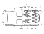
- FIG. 4 is a diagram showing a configuration example of the in-vehicle sensor 26 and the image display unit 93.
- FIG. 5 is a diagram showing a display example of the image IM provided as the content CT.
- the image display unit 93 is arranged so as to separate the front row seats (driver's seat and front passenger seat) and the rear row seats.
- a camera CM is installed in the vehicle for monitoring the passenger PA in the back row seat.
- the camera CM functions as an in-vehicle sensor 26 .
- two cameras CM monitor the entire interior space (rear space) behind the front row seats.
- the DMS 30 acquires the viewing state information VS of the passenger PA in the rear space based on the image captured by the camera CM.
- the viewing state information VS includes, for example, information regarding the number of passengers PA, whether the passengers PA are awake, the visual field of the passengers PA, and whether the passengers PA are gazing at the content CT. .
- the visual field of the passenger PA, whether the passenger PA is awake, and whether the passenger PA is gazing at the content CT is determined.
- the HMI 31 controls display of the content CT based on the viewing state information VS.
- the image display unit 93 is an optical see-through type or video see-through type display capable of transparently displaying the background.
- an optical see-through display is used as the image display unit 93 as an example.
- a known transparent display or technology such as HUD (Head-Up Display), transparent OLED (Organic Light Emitting Diode), and transparent LED (Light Emitting Diode) is used.
- HUD Head-Up Display
- transparent OLED Organic Light Emitting Diode
- transparent LED Light Emitting Diode
- the video display unit 93 has, for example, a transparent screen SCR and a projector PJ.
- the transparent screen SCR has an optical lens film that reflects the light projected from the projector PJ.
- a light control film capable of electrically controlling the transmittance of external light is laminated on the optical lens film.
- the HMI 31 adjusts the brightness of the display or the transparency or haze of the image display section 93 (transparent screen SCR) based on the brightness information outside the vehicle extracted from the environment information CE.
- the passenger PA can see through the scenery outside the vehicle through the transparent screen SCR from the gap between the driver's seat and the passenger's seat.
- FIG. 6 is a diagram showing another configuration example of the video display unit 93.
- FIG. 7 is a diagram showing a display example of the image IM provided as the content CT.
- the image display unit 93 is installed on the side of the passenger PA on the back row seat.
- the side glass (window WD: see FIG. 8) of the vehicle 1 has been replaced by a transparent screen SCR.
- a film-like transparent screen may be attached to the surface of the side glass or sandwiched inside the side glass.
- the side glass of the rear seat has the function of the transparent screen SCR, but what has the function of the transparent screen SCR is not limited to the side glass of the rear seat.
- the windshield, the front side windows or the rear window may have the function of the transparent screen SCR.
- FIG. 8 is a diagram showing another configuration example of the video display unit 93. As shown in FIG. 8
- the video display unit 93 may employ a configuration that projects the content CT onto a non-transparent screen NTS such as a window frame WF.
- a non-transparent screen NTS such as a window frame WF.
- window frame WF, pillar PL and armrest AM are used as non-transparent screen NTS.
- the desk may be used as the non-transparent screen NTS.
- FIG. 9 is a diagram showing an example of a functional configuration related to video display of the vehicle 1. As shown in FIG.
- the vehicle control system 11 is an information processing system that controls the vehicle 1 in an integrated manner.
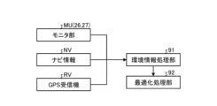
- the vehicle control system 11 has a processing section 90 , a camera CM, a GPS receiver RV, a video display section 93 and a storage section 28 .
- the processing unit 90 is an information processing device that processes various types of information. Processing unit 90 provides functionality for receiving user input information and displaying graphics to passenger PA.
- the processing unit 90 has a general OS control layer that performs multi-content rendering control and gesture detection such as touch operations.
- the processing unit 90 determines a drawing method for the content CT based on the navigation information NV and the signal received by the GPS receiver RV.
- the processing unit 90 determines the operation of the device or application by the passenger PA based on the sensing information of the camera CM.
- Navi information NV refers to information from a general car navigation system.
- the navigation information NV includes information on the destination and travel route.
- GPS receiver RV refers to a common satellite positioning system. GPS receiver RV receives a signal indicating the current position of vehicle 1 .
- the GPS receiver RV is included in the location information acquisition unit 24 .
- the camera CM analyzes the image of the image sensor IS acquired through the filter FL and senses the human body.
- Camera CM is included in in-vehicle sensor 26 .
- the processing unit 90 determines which filter FL to use for sensing based on the environment outside the vehicle.
- the control unit CU drives the actuator AC based on the determined sensing method to change the filter FL.
- infrared rays are emitted from the light emitting element LE.
- the processing unit 90 has an environment information processing unit 91 , an optimization processing unit 92 , a sensor information processing unit 94 , an output information creation unit 95 and a communication unit 22 .
- the environmental information processing unit 91 acquires the navigation information NV from the driving support/automatic driving control unit 29.
- the environmental information processing unit 91 identifies the current position of the vehicle 1 based on the signal received by the GPS receiver RV.
- the environmental information processing unit 91 identifies the travel route from the current location based on the navigation information NV, and acquires a map around the travel route from the map information storage unit 23 .
- the environment information processing unit 91 accesses information on the Internet via the communication unit 22 as necessary and acquires weather information for each travel position. As a result, route information (travel route, map around the travel route, and weather information for each travel position) toward the destination is acquired. Based on the route information, the environment information processing unit 91 predicts changes in the environment outside the vehicle during viewing of the content CT.
- the optimization processing unit 92 determines the drawing method of the content CT based on the predicted transition of the environment outside the vehicle. For example, the environment information processing unit 91 generates environment information indicating the prediction result of the environment outside the vehicle for each time, and transmits the environment information to the optimization processing unit 92 .
- the environmental information includes, for example, the driving position of the vehicle 1, the weather at the driving position, the driving direction, a surrounding map outside the vehicle, and the brightness (illuminance) of the environment outside the vehicle.
- the optimization processing unit 92 determines drawing conditions (appropriate drawing conditions) according to the predicted environment outside the vehicle for each time.
- the optimization processing unit 92 determines a drawing method (optimal drawing conditions) based on statistical results of drawing conditions for each time. As a result, the drawing method can be optimized.
- a drawing method determination algorithm is defined in the drawing rule storage unit DR.
- the optimization processing unit 92 determines the sensing method of the camera CM based on the predicted transition of the environment outside the vehicle. For example, the optimization processing unit 92 determines a sensing method (appropriate sensing method) according to the predicted environment outside the vehicle for each time. The optimization processing unit 92 determines a sensing method (optimal sensing conditions) based on statistical results of appropriate sensing methods for each time. This optimizes the sensing method.
- sensing of the passenger PA is performed based on the visible light image. If a dark environment is expected, sensing of the passenger PA is performed based on the infrared image.
- a sensing method determination algorithm is defined in the sensing method storage unit SM.
- the sensor information processing unit 94 determines the operation of the device or application that performs the passenger PA based on the sensing information of the camera CM.
- the output information creation unit 95 creates drawing information (content CT) according to the operation of the passenger PA, and outputs it to the image display unit 93 .
- the video display unit 93 draws the drawing information by the drawing method determined by the optimization processing unit 92 .
- the optimization processing unit 92 can change the drawing method and sensing method optimized according to the prediction result according to the environment outside the vehicle.
- the sensing method change algorithm is defined in the sensing change rule definition part SCM.
- the rendering method change algorithm is specified in the rendering change rule definition section DCR.
- the sensing method of the passenger PA would change from being based on visible light images to being based on infrared images.
- it was planned to draw on the window WD because a dark landscape was expected, but in reality, if drawing on the window WD becomes inappropriate due to the influence of streetlights, etc., the drawing position will be changed to a position other than the window WD. (for example, an armrest AM, a desk installed in the car, etc.).
- the storage unit 28 stores a product characteristic definition unit PC, a sensing method storage unit SM, a sensing change rule definition unit SCM, a drawing rule storage unit DR, and a drawing change rule definition unit DCR.
- the product characteristic definition part PC defines the characteristic (product characteristic) of the product in which the vehicle control system 11 is installed.
- Product characteristics include information about mobility and display type. “Mobility” indicates whether the product is mobile like a car or fixed like a digital signage. "Display type" indicates whether the display is transparent.
- FIG. 10 is a diagram illustrating an example of a control flow relating to a drawing method determination process.
- the environment information processing section 91 acquires route information from the current position to the destination (step SA1). Based on the route information, the environment information processing unit 91 predicts changes in the environment outside the vehicle during viewing of the content CT (for example, a period from the current time to T seconds later) (step SA2).
- the optimization processing unit 92 optimizes the rendering method of the content CT based on changes in the environment outside the vehicle during viewing of the content CT (step SA3).
- the output information creation unit 95 creates drawing information (contents CT) according to the operation of the passenger PA (step SA4).
- the video display unit 93 draws the drawing information by the drawing method determined by the optimization processing unit 92 (step SA5).
- the processing unit 90 repeats the above-described processing until the end processing is performed by the operation of the passenger PA.
- the content CT subject to display control is content whose drawing position and/or drawing color can be changed.
- a group of icons for performing playback, stop, volume adjustment, setting change, etc. of moving image content such as movies are exemplified as targets of display control.
- the drawing position is subject to display control.
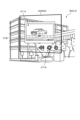
- FIG. 11 is a diagram showing a display example of the content CT on the transparent screen SCR.
- the optimization processing unit 92 determines that the sun does not enter the field of view of the passenger PA through the transparent screen SCR based on the environmental information, the optimization processing unit 92 determines the rendering position of the content CT to be the transparent screen SCR.
- the optimization processing unit 92 detects, as the background BG of the content CT, the scenery LS outside the vehicle seen through the transparent screen SCR on which the content CT is drawn.
- the optimization processing unit 92 determines the drawing color COL2 of the content CT based on the color COL1 of the background BG.
- the optimization processing unit 92 determines the complementary color of the background BG color COL1 as the drawing color COL2.
- the content CT is superimposed on a tree with green leaves. Therefore, purple, which is a complementary color of green, is determined as the drawing color COL2 of the content CT.
- FIG. 12 is a diagram showing a display example when the sun SN is viewed directly through the transparent screen SCR.
- the optimization processing unit 92 determines that the sun SN enters the field of view of the passenger PA through the transparent screen SCR based on the environmental information, the optimization processing unit 92 sets the drawing position of part or all of the content CT to the sun SN. Determine the position on the non-overlapping transparent screen SCR or the non-transparent screen NTS.
- the content CT is drawn at a position on the transparent screen SCR that does not overlap the sun SN, but it may be drawn on a non-transparent screen NTS such as the window frame WF or the pillar PL.
- the sunrise or sunset directly hits the non-transparent screen NTS.
- the optimization processing unit 92 determines that the sunrise or sunset directly hits the content rendering position on the non-transparent screen NTS based on the environment information, the optimization processing unit 92 determines orange as the color COL1 of the background BG of the content CT.
- the example of FIG. 14 is an example of drawing the content CT at a position on the non-transparent screen NTS where sunlight does not enter.
- the optimization processing unit 92 detects the non-transparent screen NTS on which the content CT is drawn as the background BG of the content CT, and determines the drawing color based on the color of the background BG. For example, when the optimization processing unit 92 determines that sunlight does not directly hit the content rendering position of the non-transparent screen NTS based on the environment information, the optimization processing unit 92 determines that the color of the material of the non-transparent screen NTS at the content rendering position is A color whose luminance is lowered is determined as the color COL1 of the background BG of the content CT.
- the content CT is drawn on the pillar PL.
- the optimization processing unit 92 determines the background color COL1 by lowering the luminance based on the color of the projection destination material. If the color of the pillar PL is gray, the background color COL1 is dark gray. The optimization processing unit 92 determines a dark gray complementary color (for example, whitish orange) as the drawing color COL2 of the content CT.
- FIG. 15 is an explanatory diagram of a prediction period during which changes in the environment outside the vehicle are predicted.
- the prediction period (T seconds) is defined for each content CT.
- the prediction period is set based on the standard time when the content CT is watched.
- the prediction period of operation-based content CT that does not require attention such as an air conditioner and a music application, is set to zero.
- the prediction period is set to 15 ⁇ 60 seconds for the content CT such as SNS and mail, which has a relatively short browsing time.
- the prediction period is set to 60 ⁇ 60 seconds for content CTs with relatively long browsing times, such as YouTube, browsers, and games.
- the prediction period is set to the playback time of the content CT.
- FIG. 16 is a flow chart showing the drawing method determination process.
- FIG. 17 is a diagram showing a table used in the drawing method determination process.
- the processing unit 90 sets the variable i to 0 (step SB1).
- the environmental information processing unit 91 acquires the travel position at the predicted time Ti based on the navigation information NV (step SB3).
- the environmental information processing unit 91 acquires the weather at the travel position at the predicted time Ti based on weather information provided by the Meteorological Agency (step SB4).
- the environmental information processing unit 91 acquires a surrounding map of the traveling position at the predicted time Ti from the map information storage unit 23 (step SB5).
- the optimization processing unit 92 detects the scenery LS outside the vehicle as the background BG of the content CT based on the traveling position and direction of the vehicle 1 at the predicted time Ti and the surrounding map outside the vehicle.
- the optimization processing unit 92 determines the drawing position and drawing color COL2 of the content CT at the predicted time Ti based on the background BG, and fills the table in FIG. 17 (steps SB6 to SB7).
- the processing unit 90 increases the value of the variable i by 1 (step SB8), and determines whether or not the prediction period (T seconds) is smaller than ⁇ t ⁇ i (step SB9).
- step SB9 If the prediction period (T seconds) is shorter than ⁇ t ⁇ i (step SB9: Yes), the optimization processing unit 92 calculates the mode and Statistical processing such as calculation of average values is performed. The optimization processing unit 92 determines the drawing method obtained by statistically processing a plurality of drawing conditions as the optimum drawing method (step SB10). When the prediction period (T seconds) is equal to or longer than ⁇ t ⁇ i (step SB9: No), the process returns to step SB2 and the processes from step SB2 to step SB9 are repeated.
- FIG. 18 is a flow showing a specific example of a method of determining a drawing position for each time.
- the optimization processing unit 92 determines whether the sun is in the field of vision of the passenger PA based on the environmental information (step SC1). If the sun is not in the field of view of the passenger PA (step SC1: No), the optimization processing unit 92 sets the drawing position to the window WD (step SC2).
- the optimization processing unit 92 determines whether the content CT to be displayed is content with a wide drawing range such as a moving image or a browser. (Step SC3). When the content CT with a wide drawing range is displayed (step SC3: Yes), the optimization processing unit 92 sets the drawing position to the window frame WF (step SC4).
- step SC5 determines whether the content CT is an application for operating air conditioners, music, or the like (step SC5). ). If the operating application is displayed as the content CT (step SC5: Yes), the optimization processing unit 92 sets the drawing position to the elbow rest AM (step SC6). If the content CT is not an operation application (step SC5: No), the optimization processing unit 92 sets the drawing position to the pillar PL (step SC7).
- FIG. 19 is a flow showing a specific example of the method of determining the drawing color COL2 for each time.
- the optimization processing unit 92 determines whether or not the drawing position is the window WD (transparent screen SCR) (step SD1). If the drawing position is the window WD (step SD1: Yes), the optimization processing unit 92 determines the background color COL1 from the traveling position of the vehicle 1 (step SD2).
- step SD1 When the drawing position is the non-transparent screen NTS (step SD1: No), the optimization processing unit 92 determines whether or not the sunlight shines into the drawing position of the content CT (step SD3). If the sunlight does not enter the content drawing position (step SD3: No), the optimization processing unit 92 sets the color of the material of the non-transparent screen NTS at the content drawing position to the background color COL1 with a lower luminance. (step SD4).
- step SD5 determines whether the altitude of the sun SN is low (sunrise or sunset) (step SD5). If the altitude of the sun SN is high (step SD5: No), the optimization processing unit 92 determines a color brighter than the material of the non-transparent screen NTS as the background color COL1 (step SD6). That is, when the optimization processing unit 92 determines that the daylight directly hits the content drawing position of the non-transparent screen NTS based on the environment information, the optimization processing unit 92 sets the luminance to the color of the material of the non-transparent screen NTS at the content drawing position. is determined as the color COL1 of the background BG. If the altitude of the sun SN is low (step SD5: Yes), the optimization processing unit 92 sets the background color COL1 to orange (step SD7).
- the optimization processing unit 92 determines the drawing color COL2 as the complementary color of the background color COL1 (step SD8). For example, if the traveling position is in a forest or a mountain, the background color COL1 is determined to be green, and the drawing color COL2 is determined to be purple. If the traveling position is a coast or an open place (a place where the sky can be seen), the background color COL1 is determined to be blue, and the drawing color COL2 is determined to be yellow. If the traveling position is along an expressway or in the city, the background color COL1 is determined to be light gray, and the drawing color COL2 is determined to be dark gray. If the traveling position is in a residential area, the background color COL1 is determined to be white, and the drawing color COL2 is determined to be black.
- FIG. 20 is a flow showing a specific example of optimization by statistical processing.
- the optimization processing unit 92 aggregates a plurality of drawing positions calculated for each predicted time Ti to calculate the occurrence frequency for each drawing position (step SE1). The optimization processing unit 92 determines the drawing position with the highest occurrence frequency as the optimum drawing position (step SE2).
- the optimization processing unit 92 extracts one or more predicted times Ti at which the drawing position is the optimum drawing position (step SE3).
- the optimization processing unit 92 aggregates the drawing colors at one or more extracted prediction times Ti, and calculates the occurrence frequency for each drawing color (step SE4).
- the optimization processing unit 92 determines the drawing color with the highest occurrence frequency as the optimum drawing color (step SE5).
- the optimization processing unit 92 determines a drawing method with the optimum drawing position and the optimum drawing color as the drawing method of the content CT.
- FIG. 21 is a diagram for explaining processing for changing the drawing method.
- the optimization processing unit 92 can temporarily change the rendering conditions for the content CT according to the conditions inside and outside the vehicle. Conditions inside and outside the vehicle are monitored by the monitor unit MU.
- the monitor unit MU includes, for example, an external recognition sensor 25 and an in-vehicle sensor 26 .
- the environment information processing unit 91 detects the surrounding situation of the vehicle 1 and the viewing environment inside the vehicle based on the monitoring result of the monitor unit MU.
- the optimization processing unit 92 temporarily changes the drawing method that is performed under the optimum drawing conditions based on the surrounding conditions of the vehicle 1 and the viewing environment inside the vehicle. Specific examples are shown below.
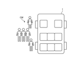
- FIGS. 22 and 23 are diagrams showing examples of modifications of the drawing method according to the surrounding conditions of the vehicle 1.
- FIG. 22 and 23 are diagrams showing examples of modifications of the drawing method according to the surrounding conditions of the vehicle 1.
- the visibility of the content CT changes according to the circumstances around the vehicle 1, which is the background BG.
- the passenger PA will simultaneously observe the movement of the crowd passing the transparent screen SCR while gazing at the content CT.
- autonomic nerves are out of sync, and symptoms similar to motion sickness (image sickness) may appear.
- the drawing position is changed to a position that avoids the crowd CW.
- the optimization processing unit 92 determines that the crowd CW outside the vehicle enters the field of view of the passenger PA through a specific transparent screen SCR
- the rendering position of part or all of the content CT is set to a specific transparent screen SCR. Determine transparent screen SCR or non-transparent screen NTS other than screen SCR.
- the drawing position is changed to the window WD on the right side of the vehicle 1 at a position where the crowd CW is not seen through.
- the drawing position is changed to the transparent screen SCR in the center of the vehicle 1 shown in FIG. 4 or the non-transparent screen NTS such as the elbow rest AM.
- FIG. 24 is a diagram showing an example of the flow of motion sickness countermeasures.
- the monitor unit MU monitors the situation around the vehicle 1 using the camera 51 facing outside the vehicle (step SF1).
- the environmental information processing unit 91 detects one or more people in the position of the background BG of the content CT based on the monitoring result, and supplies information on the number of people and the positions of the people to the optimization processing unit 92 (step SF2).
- the optimization processing unit 92 determines whether the number of people present in the background BG is equal to or greater than the threshold (step SF3). If the number of people is less than the threshold (step SF3: No), the optimization processing unit 92 determines the drawing position to be the window WD (step SF4).
- step SF3 determines whether there are people on both sides (right and left sides) of the vehicle 1 (step SF5). If there is a person on only one side of the vehicle 1 (step SF5: No), the optimization processing unit 92 determines the drawing position to be the window WD on the side where the person is not (step SF6). If there are people on both sides of the vehicle 1 (step SF5: Yes), the optimization processing unit 92 determines the drawing position to be the elbow rest AM or a desk installed inside the vehicle (step SF7).
- FIG. 25 is a diagram showing a modification of the drawing method according to the viewing environment inside the vehicle.
- the maximum drawing size of the content CT changes according to changes in the shape of the projection target. For example, when the window WD is half open, only content CT of half size can be displayed in the window WD compared to when the window WD is closed.
- the optimization processing unit 92 determines the drawing position of part or all of the content CT to be drawn on the transparent screen SCR on the non-transparent screen NTS based on the opening/closing amount of the window WD used as the transparent screen SCR.
- the cross-media bar CMB is displayed as the content CT.
- the cross-media bar CMB is a UI (User Interface) that displays horizontal and vertical icon groups by function.
- the first drawing method of drawing the content CT in the window WD is adopted. If the window WD is not completely closed, a second drawing method is adopted that draws the content CT on the closed portion of the window WD and/or the non-transparent screen NTS. When the window WD is fully open, a third drawing method is adopted for drawing the content CT on the non-transparent screen NTS.
- the content CT is composed of horizontal and vertical icon groups. If the window WD is completely closed, all horizontal and vertical icon groups are drawn in the window WD. When the window WD is not completely closed, the horizontal icon group is drawn on the horizontally long window WD which is half-opened, and the vertical icon group is drawn on the vertically long pillar PL. When the window WD is fully open, the horizontal icon group is drawn on the horizontal window frame WF, and the vertical icon group is drawn on the vertically long pillar PL.
- FIG. 26 is a diagram showing an example of the flow of countermeasures against opening and closing the window WD.
- the monitor unit MU uses the camera CM facing inside the vehicle to monitor the opening/closing status of the window WD.
- the environmental information processing unit 91 acquires information on the degree of opening of the window WD based on the monitoring result, and supplies the information to the optimization processing unit 92 (step SG1).
- the optimization processing unit 92 determines whether the window WD is completely closed (step SG2). If the window WD is completely closed (step SG2: Yes), the optimization processor 92 adopts the first drawing method (step SG3).
- step SG4 determines whether the window WD is fully open (step SG4). If the window WD is not fully open (step SG4: No), the optimization processor 92 adopts the second drawing method (step SG5). If the window WD is fully open (step SG4: Yes), the optimization processor 92 adopts the third drawing method (step SG6).
- FIGS. 27A and 27B are diagrams for explaining a drawing method determination process that does not involve prediction of changes in the environment outside the vehicle.
- the optimization processing unit 92 can also determine the drawing method at the current position based on the environment outside the vehicle at the current position without predicting changes in the environment outside the vehicle.
- cameras installed inside or outside the vehicle (camera CM, camera 51) monitor the scenery outside the vehicle LS or the color of the material of the non-transparent screen NTS in real time.
- the background color COL1 can be detected at the same time, and the highly distinguishable drawing color COL2 can be determined.
- FIG. 28 is a flowchart showing the drawing method determination process that does not involve prediction of changes in the environment outside the vehicle.
- the optimization processing unit 92 determines whether the prediction period is 0 (step SH1). If the prediction period is not 0 (step SH1: No), the optimization processing unit 92 predicts the transition of the environment outside the vehicle based on the route information, and determines the drawing method based on the prediction result (step SH8). When the prediction period is 0 (step SH1: Yes), the optimization processing unit 92 determines whether the drawing position is the window WD (step SH2).
- the optimization processing unit 92 acquires the captured image of the non-transparent screen NTS to be projected from the camera CM (step SH3).
- the optimization processing unit 92 detects the color of the material of the non-transparent screen NTS from the image captured by the camera CM.
- the optimization processing unit 92 sets the detected color of the material as the background color COL1 (step SH4), and sets the complementary color of the background color COL1 as the drawing color (step SH7).
- the optimization processing unit 92 acquires the captured image of the scenery LS outside the window WD from the camera 51 (step SH5).
- the optimization processing unit 92 detects the color of the scenery LS in the portion superimposed on the content CT from the image captured by the camera 51 .
- the optimization processing unit 92 sets the color of the detected scenery LS as the background color COL1 (step SH6), and sets the complementary color of the background color COL1 as the drawing color (step SH7).
- FIG. 29 is a diagram illustrating a method of determining the drawing color COL2 considering the content CT.
- moving image content such as movies is shown as an example of the content CT described above.
- the moving image content includes main video CT-A and icon group CT-B.
- the icon group CT-B is used to play, stop, adjust the volume, change settings, etc. of the main video CT-A.
- the optimization processing unit 92 displays the frame FLM surrounding the main video CT-A superimposed on the background BG. Any color may be used for the frame FLM as long as it is highly distinguishable from the background BG.
- a frame FLM may be displayed in a single color or in multiple colors.
- the shape of the frame FLM is also set according to the shape of the object to be surrounded, and any shape such as a circle or a square is possible. In the example of FIG. 29, a monochromatic rectangular frame FLM bordering the feature video CT-A is displayed.
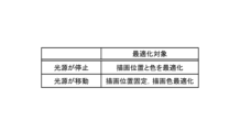
- the optimization processing unit 92 sets an appropriate drawing color COL2 according to the background color COL1, thereby enhancing the distinguishability from the background BG.
- the icon group CT-B is superimposed on the tree (green leaves). Therefore, the optimization processing unit 92 recognizes the background color COL1 as green, and sets the drawing color COL2 to pink (complementary color of green).
- FIG. 30 is a diagram for explaining the correspondence to light sources other than the sun SN.
- Similar optimization can be performed even in the presence of light sources other than the sun SN (tunnel lights, street lights, etc.). That is, when the optimization processing unit 92 determines that the light source enters the visual field of the passenger PA through the transparent screen SCR, the rendering position of part or all of the content CT is set on the transparent screen SCR that does not overlap with the light source. or the non-transparent screen NTS. This enhances the visibility of the content CT.
- the optimization processing unit 92 varies the method of optimizing the drawing method according to the movement state of the light source. For example, when the light source is stopped within the field of view of the passenger PA, the optimization processing unit 92 optimizes both the drawing position and the drawing color by the method described above. When the light source is moving within the visual field of the passenger PA, the optimization processing unit 92 fixes the drawing position and optimizes the drawing color. Whether or not the light source is moving is determined, for example, based on the movement of the shadow inside the vehicle caused by the light source.
- FIG. 31 is a flow chart showing the drawing method determination process based on the moving state of the light source.
- the shadow inside the car caused by the light source is photographed by the camera CM for t seconds (step SI1).
- the shooting time (t seconds) is arbitrarily set as a time during which the movement of the shadow can be determined.
- the environmental information processing unit 91 calculates the moving speed of the shadow based on the image of the shadow (visible light image) obtained from the camera CM, and supplies the moving speed to the optimization processing unit 92 .
- the optimization processing unit 92 determines whether the position of the shadow has changed based on the moving speed of the shadow (step SI2). For example, if the moving speed of the shadow is equal to or greater than a threshold, it is determined that the position of the shadow has changed. If the moving speed of the shadow is less than the threshold, it is determined that the position of the shadow has not changed.
- step SI2 determines that the light source is stopped, and optimizes only the drawing color of the content CT by the method described above (step SI3). If the position of the shadow has changed (step SI2: Yes), the optimization processing unit 92 determines that the light source has moved, and adjusts both the drawing position and drawing color of the content CT by the method described above. Optimize (step SI4).
- the processing unit 90 has an environment information processing unit 91 and an optimization processing unit 92 .
- the environment information processing unit 91 predicts changes in the environment outside the vehicle during viewing of the content CT.
- the optimization processing unit 92 determines a drawing method for the content CT based on the predicted transition of the environment outside the vehicle.
- the processing of the processing unit 90 is executed by a computer.
- the program of the present disclosure causes the computer to implement the processing of the processing unit 90 .
- the vehicle control system 11 of the present disclosure has a video display section 93 that draws the content CT based on the drawing method determined by the processing section 90 .
- an appropriate drawing method is determined that takes into account changes in the environment outside the vehicle. Therefore, the visibility of the content CT is less likely to deteriorate due to changes in the environment outside the vehicle.
- the environment information processing unit 91 generates environment information indicating prediction results of the environment outside the vehicle for each time.
- the optimization processing unit 92 determines drawing conditions according to the predicted environment outside the vehicle for each time, and decides a drawing method based on statistical results of the drawing conditions for each time.
- the drawing method is less likely to change frequently due to changes in the environment outside the vehicle.
- Environmental information includes information on the driving position, the weather at the driving position, the driving direction, and the surrounding map outside the vehicle.
- the rendering method is optimized based on the driving scenery and weather changes.
- the drawing conditions include the drawing position and drawing color COL2.
- the drawing position and drawing color COL2 are prevented from being frequently changed due to changes in the environment outside the vehicle.
- the optimization processing unit 92 aggregates a plurality of drawing positions calculated for each time and calculates the occurrence frequency for each drawing position.
- the optimization processing unit 92 determines the drawing position with the highest occurrence frequency as the optimum drawing position.
- the optimization processing unit 92 extracts one or more times when the drawing position is the optimum drawing position.
- the optimization processing unit 92 aggregates the extracted drawing colors COL2 at one or more times to calculate the occurrence frequency for each drawing color COL2.
- the optimization processing unit 92 determines the drawing color COL2 with the highest occurrence frequency as the optimum drawing color.
- the optimization processing unit 92 determines a drawing method with the optimum drawing position and the optimum drawing color as the drawing method of the content CT.
- the optimum drawing method is determined according to the drawing position calculated for each time and the appearance frequency of the drawing color COL2.
- the optimization processing unit 92 detects, as the background BG of the content CT, the scenery LS outside the vehicle seen through the non-transparent screen NTS that is the drawing target of the content CT or the transparent screen SCR that is the drawing target of the content CT. .
- the optimization processing unit 92 determines the drawing color COL2 based on the color of the background BG.
- the content CT is better distinguished from the background BG.
- the optimization processing unit 92 determines that the sunlight does not directly hit the content drawing position of the non-transparent screen NTS based on the environment information, the optimization processing unit 92 adjusts the luminance for the color of the material of the non-transparent screen NTS at the content drawing position. The lowered color is determined as the background BG color.
- an appropriate drawing color COL2 is determined in consideration of the color of the material of the non-transparent screen NTS to be drawn.
- the optimization processing unit 92 determines that daylight directly hits the content drawing position of the non-transparent screen NTS based on the environment information, the optimization processing unit 92 increases the brightness of the material color of the non-transparent screen NTS at the content drawing position. The resulting color is determined as the color of the background BG.
- an appropriate drawing color COL2 is determined in consideration of the brightness of the sunlight (daylight) that directly hits the content drawing position.
- the optimization processing unit 92 determines that the sunrise or sunset will directly hit the content drawing position of the non-transparent screen NTS based on the environment information, it determines orange as the color of the background BG.
- an appropriate drawing color COL2 is determined in consideration of the color of the sunrise or sunset (orange).
- the optimization processing unit 92 detects the scenery LS outside the vehicle as the background BG of the content CT based on the travel position, the travel direction, and the surrounding map outside the vehicle.
- the scenery LS outside the vehicle is better estimated.
- the optimization processing unit 92 determines the complementary color of the background BG as the drawing color COL2.
- the content CT is better distinguished from the background BG.
- the optimization processing unit 92 determines that the sun SN does not enter the field of view of the passenger PA through the transparent screen SCR based on the environmental information, the optimization processing unit 92 determines the rendering position of the content CT to be the transparent screen SCR.
- the optimization processing unit 92 determines that the sun SN enters the field of view of the passenger PA through the transparent screen SCR based on the environmental information, the optimization processing unit 92 sets the drawing position of part or all of the content CT to the sun SN. Determine the position on the non-overlapping transparent screen SCR or the non-transparent screen NTS.
- the content CT is presented at a position where the sun SN is not viewed directly.
- the optimization processing unit 92 determines that the crowd CW outside the vehicle enters the field of view of the passenger PA through the specific transparent screen SCR, the optimization processing unit 92 shifts the drawing position of part or all of the content CT to the specific transparent screen SCR. Decide on a transparent screen SCR or a non-transparent screen NTS.
- the optimization processing unit 92 determines the drawing position of part or all of the content CT to be drawn on the transparent screen SCR on the non-transparent screen NTS based on the opening/closing amount of the window WD used as the transparent screen SCR.
- the visibility of the content CT is less likely to deteriorate due to the opening and closing of the window WD.
- the prediction period during which changes in the environment outside the vehicle are predicted is defined for each content CT.
- an appropriate prediction period is set according to the content CT.
- the prediction period is set based on the standard time when the content CT is watched.
- the present technology can also adopt the following configuration.
- an environment information processing unit that predicts changes in the environment outside the vehicle while viewing content; an optimization processing unit that determines a rendering method of the content based on the predicted transition of the environment outside the vehicle;
- Information processing device having (2)
- the environment information processing unit generates environment information indicating a prediction result of the environment outside the vehicle for each time,
- the optimization processing unit determines drawing conditions according to the predicted environment outside the vehicle for each time, and determines the drawing method based on statistical results of the drawing conditions for each time.
- the environment information includes information on the driving position, the weather at the driving position, the driving direction, and a surrounding map outside the vehicle.
- the drawing conditions include a drawing position and a drawing color, The information processing apparatus according to (2) or (3) above.
- the optimization processing unit a plurality of drawing positions calculated for each time are aggregated to calculate the occurrence frequency for each drawing position; determining the rendering position with the highest occurrence frequency as the optimal rendering position; extracting one or more times when the drawing position is the optimum drawing position; aggregating the extracted drawing colors at the one or more times to calculate the occurrence frequency for each of the drawing colors; determining the drawing color with the highest occurrence frequency as the optimum drawing color; determining, as the rendering method of the content, a rendering method having an optimal rendering position and an optimal rendering color as optimal rendering conditions; The information processing apparatus according to (4) above.
- the optimization processing unit detects, as a background of the content, a scenery outside the vehicle seen through a non-transparent screen on which the content is drawn or a transparent screen on which the content is drawn, and determining the drawing color based on the color; The information processing apparatus according to (4) or (5) above.
- the optimization processing unit determines, based on the environment information, that the sunlight does not directly hit the content drawing position of the non-transparent screen, the brightness of the material color of the non-transparent screen at the content drawing position is determined as the color of the background by lowering the The information processing apparatus according to (6) above.
- the optimization processing unit when determining based on the environment information that daylight directly hits the content drawing position of the non-transparent screen, adjusts the brightness of the material color of the non-transparent screen at the content drawing position. determining the elevated color as the background color; The information processing apparatus according to (6) or (7) above. (9) The optimization processing unit determines orange as the color of the background when determining that the sunrise or sunset directly hits the content rendering position on the non-transparent screen based on the environment information. The information processing apparatus according to any one of (6) to (8) above. (10) The optimization processing unit detects the scenery outside the vehicle as the background of the content based on the driving position, the driving direction, and a surrounding map outside the vehicle. The information processing apparatus according to any one of (6) to (9) above.
- the optimization processing unit determines a complementary color of the background color as the drawing color; The information processing apparatus according to any one of (6) to (10) above. (12) When the optimization processing unit determines that the sun does not enter the passenger's field of view through the transparent screen based on the environment information, the optimization processing unit determines the rendering position of the content on the transparent screen. The information processing apparatus according to any one of (6) to (11) above. (13) When the optimization processing unit determines that the sun enters the field of view of the passenger through the transparent screen based on the environment information, the optimization processing unit causes the rendering position of part or all of the content to overlap with the sun.
- the optimization processing unit determines a position on said transparent screen or a non-transparent screen that shall not be The information processing apparatus according to any one of (6) to (12) above.
- the optimization processing unit shifts the drawing position of part or all of the content to a transparent screen other than the specific transparent screen. Decide on a screen or a non-transparent screen, The information processing apparatus according to any one of (6) to (13) above.
- the optimization processing unit determines a drawing position of part or all of the content to be drawn on the transparent screen on the non-transparent screen based on the amount of opening and closing of a window used as the transparent screen.
- a prediction period for predicting changes in the environment outside the vehicle is defined for each content, The information processing apparatus according to any one of (1) to (15) above. (17) wherein the prediction period is set based on a standard time period during which the content is watched; The information processing device according to (16) above. (18) Predict changes in the environment outside the vehicle while viewing content, determining a rendering method of the content based on the predicted transition of the environment outside the vehicle; A computer-implemented information processing method, comprising: (19) Predict changes in the environment outside the vehicle while viewing content, determining a rendering method of the content based on the predicted transition of the environment outside the vehicle; A program that makes a computer do something. (20) an information processing apparatus according to any one of (1) to (17) above; a video display unit that draws the content based on the drawing method determined by the information processing device; An information processing system having
Landscapes
- Engineering & Computer Science (AREA)
- Physics & Mathematics (AREA)
- General Physics & Mathematics (AREA)
- Theoretical Computer Science (AREA)
- Computer Hardware Design (AREA)
- Mechanical Engineering (AREA)
- Traffic Control Systems (AREA)
Abstract
Description
[1.コンテンツの表示制御の概要]
[2.車両制御システムの構成例]
[3.外部認識センサのセンシング領域]
[4.映像表示部の構成例]
[5.映像表示に関する機能構成]
[6.制御フロー]
[7.表示制御例]
[7-1.透明スクリーンへのコンテンツの表示]
[7-2.太陽との重畳回避]
[7-3.非透明スクリーンへのコンテンツの表示]
[7-4.車外環境の推移の予測に基づく描画方法の最適化]
[7-4-1.予測期間]
[7-4-2.描画方法の決定]
[7-4-3.描画位置および描画色の具体例]
[7-5.描画方法の変更]
[7-5-1.映像酔い対策]
[7-5-2.投影対象の形状変化への対策]
[7-6.予測を伴わない描画方法の決定]
[7-7.コンテンツを考慮した描画色の決定]
[7-8.太陽以外の光源への対応]
[8.効果]
図1は、コンテンツCTの表示制御の概要を説明する図である。
図2は、車両制御システム11の構成例を示すブロック図である。
図3は、外部認識センサ25のカメラ51、レーダ52、LiDAR53、及び、超音波センサ54等によるセンシング領域の例を示す図である。なお、図3は、車両1を上面から見た様子を模式的に示している。符号が正しい向きで表示されるような姿勢で図3を見た場合、左端側が車両1の前端(フロント)側であり、右端側が車両1の後端(リア)側となっている。
図4は、車内センサ26および映像表示部93の構成例を示す図である。図5は、コンテンツCTとして提供される映像IMの表示例を示す図である。
図9は、車両1の映像表示に関する機能構成の一例を示す図である。
図10は、描画方法の決定処理に関する制御フローの一例を示す図である。
以下、コンテンツCTの表示制御の具体例を示す。表示制御の対象となるコンテンツCTは、描画位置および描画色の少なくとも一方を変更可能なコンテンツである。以下の例では、映画などの動画コンテンツの再生、停止、音量調整および設定変更などを行うアイコン群が表示制御の対象として例示される。動画コンテンツのうち、本編映像については、色の変更ができないため、描画位置のみが表示制御の対象となる。
図11は、透明スクリーンSCRへのコンテンツCTの表示例を示す図である。
図12は、透明スクリーンSCRを介して太陽SNが直視される場合の表示例を示す図である。
図13および図14は、非透明スクリーンNTSへのコンテンツCTの表示例を示す図である。
以下、図15ないし図20を用いて、車外環境の推移の予測に基づく描画方法の最適化について具体的に説明する。
図15は、車外環境の推移の予測が行われる予測期間の説明図である。
図16は、描画方法の決定処理を示すフローチャートである。図17は、描画方法の決定処理に用いられるテーブルを示す図である。
図18は、時刻ごとの描画位置の決定方法の具体例を示すフローである。
図21は、描画方法の変更処理を説明する図である。
図22および図23は、車両1の周辺状況に応じた描画方法の変更例を示す図である。
図25は、車内の視聴環境に応じた描画方法の変更例を示す図である。
図27は、車外環境の推移の予測を伴わない描画方法の決定処理を説明する図である。
図29は、コンテンツCTを考慮した描画色COL2の決定方法を説明する図である。
図30は、太陽SN以外の光源への対応を説明する図である。
処理部90は、環境情報処理部91と最適化処理部92とを有する。環境情報処理部91は、コンテンツCTの視聴中の車外環境の推移を予測する。最適化処理部92は、予測される車外環境の推移に基づいてコンテンツCTの描画方法を決定する。本開示の情報処理方法は、処理部90の処理がコンピュータにより実行される。本開示のプログラムは、処理部90の処理をコンピュータに実現させる。本開示の車両制御システム11は、処理部90により決定された描画方法に基づいてコンテンツCTを描画する映像表示部93を有する。
なお、本技術は以下のような構成も採ることができる。
(1)
コンテンツの視聴中の車外環境の推移を予測する環境情報処理部と、
予測される前記車外環境の推移に基づいて前記コンテンツの描画方法を決定する最適化処理部と、
を有する情報処理装置。
(2)
前記環境情報処理部は、時刻ごとの前記車外環境の予測結果を示す環境情報を生成し、
前記最適化処理部は、前記時刻ごとに、予測される前記車外環境に応じた描画条件を決定し、前記時刻ごとの描画条件の統計結果に基づいて前記描画方法を決定する、
上記(1)に記載の情報処理装置。
(3)
前記環境情報は、走行位置、前記走行位置の天気、前記走行方向および車外の周辺マップに関する情報を含む、
上記(2)に記載の情報処理装置。
(4)
前記描画条件は、描画位置および描画色を含む、
上記(2)または(3)に記載の情報処理装置。
(5)
前記最適化処理部は、
時刻ごとに算出された複数の描画位置を集計して前記描画位置ごとの発現頻度を算出し、
最も前記発現頻度が高い前記描画位置を最適描画位置と決定し、
前記描画位置が前記最適描画位置である1以上の時刻を抽出し、
抽出された前記1以上の時刻における描画色を集計して前記描画色ごとの発現頻度を算出し、
最も前記発現頻度が高い前記描画色を最適描画色と決定し、
最適描画位置および最適描画色を最適描画条件とする描画方法を前記コンテンツの前記描画方法として決定する、
上記(4)に記載の情報処理装置。
(6)
前記最適化処理部は、前記コンテンツの描画対象である非透明スクリーン、または、前記コンテンツの描画対象である透明スクリーンを介して透視される車外の風景を前記コンテンツの背景として検出し、前記背景の色に基づいて前記描画色を決定する、
上記(4)または(5)に記載の情報処理装置。
(7)
前記最適化処理部は、前記環境情報に基づいて太陽光が前記非透明スクリーンのコンテンツ描画位置に直射しないと判定した場合には、前記コンテンツ描画位置における非透明スクリーンの素材の色に対して輝度を低くした色を前記背景の色として決定する、
上記(6)に記載の情報処理装置。
(8)
前記最適化処理部は、前記環境情報に基づいて昼光が前記非透明スクリーンのコンテンツ描画位置に直射すると判定した場合には、前記コンテンツ描画位置における非透明スクリーンの素材の色に対して輝度を高くした色を前記背景の色として決定する、
上記(6)または(7)に記載の情報処理装置。
(9)
前記最適化処理部は、前記環境情報に基づいて朝日または夕日が前記非透明スクリーンのコンテンツ描画位置に直射すると判定した場合には、オレンジ色を前記背景の色として決定する、
上記(6)ないし(8)のいずれか1つに記載の情報処理装置。
(10)
前記最適化処理部は、走行位置、走行方向および車外の周辺マップに基づいて、前記コンテンツの背景となる前記車外の風景を検出する、
上記(6)ないし(9)のいずれか1つに記載の情報処理装置。
(11)
前記最適化処理部は、前記背景の色の補色を前記描画色として決定する、
上記(6)ないし(10)のいずれか1つに記載の情報処理装置。
(12)
前記最適化処理部は、前記環境情報に基づいて、太陽が前記透明スクリーンを介して搭乗者の視界に入らないと判定した場合には、前記コンテンツの描画位置を前記透明スクリーンに決定する、
上記(6)ないし(11)のいずれか1つに記載の情報処理装置。
(13)
前記最適化処理部は、前記環境情報に基づいて、太陽が前記透明スクリーンを介して搭乗者の視界に入ると判定した場合には、前記コンテンツの一部または全部の描画位置を前記太陽と重ならない前記透明スクリーン上の位置または非透明スクリーンに決定する、
上記(6)ないし(12)のいずれか1つに記載の情報処理装置。
(14)
前記最適化処理部は、車外の群衆が特定の透明スクリーンを介して搭乗者の視界に入ると判定した場合には、前記コンテンツの一部または全部の描画位置を前記特定の透明スクリーン以外の透明スクリーンまたは非透明スクリーンに決定する、
上記(6)ないし(13)のいずれか1つに記載の情報処理装置。
(15)
前記最適化処理部は、前記透明スクリーンとして用いられる窓の開閉量に基づいて、前記透明スクリーンに描画すべき前記コンテンツの一部または全部の描画位置を前記非透明スクリーンに決定する、
上記(6)ないし(14)のいずれか1つに記載の情報処理装置。
(16)
前記車外環境の推移の予測が行われる予測期間は、前記コンテンツごとに規定される、
上記(1)ないし(15)のいずれか1つに記載の情報処理装置。
(17)
前記予測期間は、前記コンテンツが注視される標準的な時間に基づいて設定される、
上記(16)に記載の情報処理装置。
(18)
コンテンツの視聴中の車外環境の推移を予測し、
予測される前記車外環境の推移に基づいて前記コンテンツの描画方法を決定する、
ことを有する、コンピュータにより実行される情報処理方法。
(19)
コンテンツの視聴中の車外環境の推移を予測し、
予測される前記車外環境の推移に基づいて前記コンテンツの描画方法を決定する、
ことをコンピュータに実現させるプログラム。
(20)
上記(1)ないし(17)のいずれか1つに記載の情報処理装置と、
前記情報処理装置により決定された前記描画方法に基づいて前記コンテンツを描画する映像表示部と、
を有する情報処理システム。
90 処理部(情報処理装置)
91 環境情報処理部
92 最適化処理部
93 映像表示部
BG 背景
COL1背景色
COL2 描画色
CT コンテンツ
LS 風景
NTS 非透明スクリーン
PA 搭乗者
SCR 透明スクリーン
SN 太陽
WD 窓
Claims (20)
- コンテンツの視聴中の車外環境の推移を予測する環境情報処理部と、
予測される前記車外環境の推移に基づいて前記コンテンツの描画方法を決定する最適化処理部と、
を有する情報処理装置。 - 前記環境情報処理部は、時刻ごとの前記車外環境の予測結果を示す環境情報を生成し、
前記最適化処理部は、前記時刻ごとに、予測される前記車外環境に応じた描画条件を決定し、前記時刻ごとの描画条件の統計結果に基づいて前記描画方法を決定する、
請求項1に記載の情報処理装置。 - 前記環境情報は、走行位置、前記走行位置の天気、走行方向および車外の周辺マップに関する情報を含む、
請求項2に記載の情報処理装置。 - 前記描画条件は、描画位置および描画色を含む、
請求項2に記載の情報処理装置。 - 前記最適化処理部は、
時刻ごとに算出された複数の描画位置を集計して前記描画位置ごとの発現頻度を算出し、
最も前記発現頻度が高い前記描画位置を最適描画位置と決定し、
前記描画位置が前記最適描画位置である1以上の時刻を抽出し、
抽出された前記1以上の時刻における描画色を集計して前記描画色ごとの発現頻度を算出し、
最も前記発現頻度が高い前記描画色を最適描画色と決定し、
最適描画位置および最適描画色を最適描画条件とする描画方法を前記コンテンツの前記描画方法として決定する、
請求項4に記載の情報処理装置。 - 前記最適化処理部は、前記コンテンツの描画対象である非透明スクリーン、または、前記コンテンツの描画対象である透明スクリーンを介して透視される車外の風景を前記コンテンツの背景として検出し、前記背景の色に基づいて前記描画色を決定する、
請求項4に記載の情報処理装置。 - 前記最適化処理部は、前記環境情報に基づいて太陽光が前記非透明スクリーンのコンテンツ描画位置に直射しないと判定した場合には、前記コンテンツ描画位置における非透明スクリーンの素材の色に対して輝度を低くした色を前記背景の色として決定する、
請求項6に記載の情報処理装置。 - 前記最適化処理部は、前記環境情報に基づいて昼光が前記非透明スクリーンのコンテンツ描画位置に直射すると判定した場合には、前記コンテンツ描画位置における非透明スクリーンの素材の色に対して輝度を高くした色を前記背景の色として決定する、
請求項6に記載の情報処理装置。 - 前記最適化処理部は、前記環境情報に基づいて朝日または夕日が前記非透明スクリーンのコンテンツ描画位置に直射すると判定した場合には、オレンジ色を前記背景の色として決定する、
請求項6に記載の情報処理装置。 - 前記最適化処理部は、走行位置、走行方向および車外の周辺マップに基づいて、前記コンテンツの背景となる前記車外の風景を検出する、
請求項6に記載の情報処理装置。 - 前記最適化処理部は、前記背景の色の補色を前記描画色として決定する、
請求項6に記載の情報処理装置。 - 前記最適化処理部は、前記環境情報に基づいて、太陽が前記透明スクリーンを介して搭乗者の視界に入らないと判定した場合には、前記コンテンツの描画位置を前記透明スクリーンに決定する、
請求項6に記載の情報処理装置。 - 前記最適化処理部は、前記環境情報に基づいて、太陽が前記透明スクリーンを介して搭乗者の視界に入ると判定した場合には、前記コンテンツの一部または全部の描画位置を前記太陽と重ならない前記透明スクリーン上の位置または非透明スクリーンに決定する、
請求項6に記載の情報処理装置。 - 前記最適化処理部は、車外の群衆が特定の透明スクリーンを介して搭乗者の視界に入ると判定した場合には、前記コンテンツの一部または全部の描画位置を前記特定の透明スクリーン以外の透明スクリーンまたは非透明スクリーンに決定する、
請求項6に記載の情報処理装置。 - 前記最適化処理部は、前記透明スクリーンとして用いられる窓の開閉量に基づいて、前記透明スクリーンに描画すべき前記コンテンツの一部または全部の描画位置を前記非透明スクリーンに決定する、
請求項6に記載の情報処理装置。 - 前記車外環境の推移の予測が行われる予測期間は、前記コンテンツごとに規定される、
請求項1に記載の情報処理装置。 - 前記予測期間は、前記コンテンツが注視される標準的な時間に基づいて設定される、
請求項16に記載の情報処理装置。 - コンテンツの視聴中の車外環境の推移を予測し、
予測される前記車外環境の推移に基づいて前記コンテンツの描画方法を決定する、
ことを有する、コンピュータにより実行される情報処理方法。 - コンテンツの視聴中の車外環境の推移を予測し、
予測される前記車外環境の推移に基づいて前記コンテンツの描画方法を決定する、
ことをコンピュータに実現させるプログラム。 - 請求項1に記載の情報処理装置と、
前記情報処理装置により決定された前記描画方法に基づいて前記コンテンツを描画する映像表示部と、
を有する情報処理システム。
Priority Applications (3)
| Application Number | Priority Date | Filing Date | Title |
|---|---|---|---|
| US18/701,702 US20240420385A1 (en) | 2021-10-25 | 2022-09-06 | Information processing apparatus, information processing method, program, and information processing system |
| CN202280070097.6A CN118120008A (zh) | 2021-10-25 | 2022-09-06 | 信息处理装置、信息处理方法、程序和信息处理系统 |
| EP22886460.9A EP4425478A4 (en) | 2021-10-25 | 2022-09-06 | INFORMATION PROCESSING DEVICE, INFORMATION PROCESSING METHOD, PROGRAM AND INFORMATION PROCESSING SYSTEM |
Applications Claiming Priority (2)
| Application Number | Priority Date | Filing Date | Title |
|---|---|---|---|
| JP2021-173885 | 2021-10-25 | ||
| JP2021173885 | 2021-10-25 |
Publications (1)
| Publication Number | Publication Date |
|---|---|
| WO2023074126A1 true WO2023074126A1 (ja) | 2023-05-04 |
Family
ID=86157678
Family Applications (1)
| Application Number | Title | Priority Date | Filing Date |
|---|---|---|---|
| PCT/JP2022/033351 Ceased WO2023074126A1 (ja) | 2021-10-25 | 2022-09-06 | 情報処理装置、情報処理方法、プログラムおよび情報処理システム |
Country Status (4)
| Country | Link |
|---|---|
| US (1) | US20240420385A1 (ja) |
| EP (1) | EP4425478A4 (ja) |
| CN (1) | CN118120008A (ja) |
| WO (1) | WO2023074126A1 (ja) |
Cited By (2)
| Publication number | Priority date | Publication date | Assignee | Title |
|---|---|---|---|---|
| WO2025150406A1 (ja) * | 2024-01-09 | 2025-07-17 | パナソニックIpマネジメント株式会社 | 表示ユニット及び移動体 |
| EP4664444A1 (en) | 2024-06-12 | 2025-12-17 | FUJIFILM Business Innovation Corp. | Information processing system, program, and information processing method |
Families Citing this family (1)
| Publication number | Priority date | Publication date | Assignee | Title |
|---|---|---|---|---|
| CN118514708B (zh) * | 2024-07-25 | 2024-11-19 | 比亚迪股份有限公司 | 智能体控制方法、电子装置、车辆、存储介质及程序产品 |
Citations (4)
| Publication number | Priority date | Publication date | Assignee | Title |
|---|---|---|---|---|
| JPH10311732A (ja) * | 1997-05-09 | 1998-11-24 | Toyota Motor Corp | 車両用表示装置 |
| JP2015230388A (ja) * | 2014-06-05 | 2015-12-21 | 三菱電機株式会社 | 表示制御システムおよび表示制御方法 |
| US20190152303A1 (en) * | 2017-11-22 | 2019-05-23 | Ford Global Technologies, Llc | Controlling window tint levels to protect the interior cabin of an autonomous vehicle |
| JP2019162932A (ja) | 2018-03-19 | 2019-09-26 | 株式会社リコー | 画像表示装置、移動体、画像表示方法およびプログラム |
Family Cites Families (13)
| Publication number | Priority date | Publication date | Assignee | Title |
|---|---|---|---|---|
| KR101141847B1 (ko) * | 2007-03-16 | 2012-05-07 | 후지쯔 가부시끼가이샤 | 정보 처리 장치, 정보 처리 프로그램을 기록한 컴퓨터 판독 가능한 매체, 정보 처리 방법 |
| JP4932067B1 (ja) * | 2011-02-10 | 2012-05-16 | パイオニア株式会社 | 表示装置、表示方法及び表示プログラム |
| US9153195B2 (en) * | 2011-08-17 | 2015-10-06 | Microsoft Technology Licensing, Llc | Providing contextual personal information by a mixed reality device |
| US9036910B1 (en) * | 2012-09-28 | 2015-05-19 | The Boeing Company | Method and system for processing a sequence of images using fingerprints |
| JP2014172406A (ja) * | 2013-03-05 | 2014-09-22 | Funai Electric Co Ltd | ヘッドアップディスプレイ装置、ヘッドアップディスプレイ装置の表示方法およびヘッドアップディスプレイ装置のプログラム |
| US10096089B2 (en) * | 2017-01-04 | 2018-10-09 | Facebook, Inc. | Accelerated skin smoothing effect |
| US10380714B2 (en) * | 2017-09-26 | 2019-08-13 | Denso International America, Inc. | Systems and methods for ambient animation and projecting ambient animation on an interface |
| JP2019119266A (ja) * | 2017-12-28 | 2019-07-22 | 本田技研工業株式会社 | 車両制御システム、車両制御方法、およびプログラム |
| CN110219543A (zh) * | 2018-03-02 | 2019-09-10 | 上海博泰悦臻网络技术服务有限公司 | 智能车辆及其车窗智能控制方法 |
| JP7176273B2 (ja) * | 2018-07-26 | 2022-11-22 | トヨタ自動車株式会社 | 情報処理装置、情報処理方法およびプログラム |
| WO2020036057A1 (ja) * | 2018-08-16 | 2020-02-20 | ソニー株式会社 | 情報処理装置、情報処理方法、プログラム、及び移動体 |
| US11354805B2 (en) * | 2019-07-30 | 2022-06-07 | Apple Inc. | Utilization of luminance changes to determine user characteristics |
| CN110458352A (zh) * | 2019-08-06 | 2019-11-15 | 华泰证券股份有限公司 | 预测资产价格走势的方法、服务器及计算机可读存储介质 |
-
2022
- 2022-09-06 EP EP22886460.9A patent/EP4425478A4/en active Pending
- 2022-09-06 US US18/701,702 patent/US20240420385A1/en active Pending
- 2022-09-06 WO PCT/JP2022/033351 patent/WO2023074126A1/ja not_active Ceased
- 2022-09-06 CN CN202280070097.6A patent/CN118120008A/zh active Pending
Patent Citations (4)
| Publication number | Priority date | Publication date | Assignee | Title |
|---|---|---|---|---|
| JPH10311732A (ja) * | 1997-05-09 | 1998-11-24 | Toyota Motor Corp | 車両用表示装置 |
| JP2015230388A (ja) * | 2014-06-05 | 2015-12-21 | 三菱電機株式会社 | 表示制御システムおよび表示制御方法 |
| US20190152303A1 (en) * | 2017-11-22 | 2019-05-23 | Ford Global Technologies, Llc | Controlling window tint levels to protect the interior cabin of an autonomous vehicle |
| JP2019162932A (ja) | 2018-03-19 | 2019-09-26 | 株式会社リコー | 画像表示装置、移動体、画像表示方法およびプログラム |
Non-Patent Citations (1)
| Title |
|---|
| See also references of EP4425478A4 |
Cited By (2)
| Publication number | Priority date | Publication date | Assignee | Title |
|---|---|---|---|---|
| WO2025150406A1 (ja) * | 2024-01-09 | 2025-07-17 | パナソニックIpマネジメント株式会社 | 表示ユニット及び移動体 |
| EP4664444A1 (en) | 2024-06-12 | 2025-12-17 | FUJIFILM Business Innovation Corp. | Information processing system, program, and information processing method |
Also Published As
| Publication number | Publication date |
|---|---|
| EP4425478A4 (en) | 2025-03-12 |
| US20240420385A1 (en) | 2024-12-19 |
| CN118120008A (zh) | 2024-05-31 |
| EP4425478A1 (en) | 2024-09-04 |
Similar Documents
| Publication | Publication Date | Title |
|---|---|---|
| JP7852696B2 (ja) | 移動装置、情報処理装置、及び、情報処理方法 | |
| JP7663839B2 (ja) | 信号処理装置、信号処理方法、プログラム、及び、移動装置 | |
| JP7615141B2 (ja) | 情報処理装置、情報処理方法、およびプログラム | |
| US12475647B2 (en) | MR service platform providing mixed reality automotive meta service, and method for controlling same | |
| JP7786398B2 (ja) | 情報処理装置、情報処理方法、プログラム、移動装置、及び、情報処理システム | |
| JP7732463B2 (ja) | カメラモジュール、情報処理システム、情報処理方法、及び、情報処理装置 | |
| EP4425478A1 (en) | Information processing device, information processing method, program, and information processing system | |
| KR102941232B1 (ko) | 차량 | |
| WO2022158185A1 (ja) | 情報処理装置、情報処理方法、プログラムおよび移動装置 | |
| WO2023090001A1 (ja) | 情報処理装置、および情報処理方法、並びにプログラム | |
| JP7676407B2 (ja) | 情報処理装置、情報処理方法、及び、プログラム | |
| WO2021145227A1 (ja) | 情報処理装置、情報処理方法、及び、プログラム | |
| WO2023053498A1 (ja) | 情報処理装置、情報処理方法、記録媒体、および車載システム | |
| JP7856109B2 (ja) | 車両制御システム、車両制御方法およびプログラム | |
| US20250067875A1 (en) | Information processing apparatus, information processing method, and information processing program | |
| WO2023166982A1 (ja) | 情報処理装置、情報処理方法、及び、移動体 | |
| US12634544B2 (en) | Vehicle control system and vehicle control method | |
| JP7507722B2 (ja) | 情報処理プログラム及び情報処理方法 | |
| US20240386724A1 (en) | Recognition processing device, recognition processing method, and recognition processing system | |
| EP4593369A1 (en) | Information processing device and information processing method | |
| US20230377108A1 (en) | Information processing apparatus, information processing method, and program | |
| WO2024024471A1 (ja) | 情報処理装置、情報処理方法、及び、情報処理システム | |
| WO2024043053A1 (ja) | 情報処理装置、情報処理方法、及び、プログラム | |
| EP4646340A1 (en) | Information processing device and information processing method |
Legal Events
| Date | Code | Title | Description |
|---|---|---|---|
| 121 | Ep: the epo has been informed by wipo that ep was designated in this application |
Ref document number: 22886460 Country of ref document: EP Kind code of ref document: A1 |
|
| WWE | Wipo information: entry into national phase |
Ref document number: 18701702 Country of ref document: US Ref document number: 202427030621 Country of ref document: IN |
|
| WWE | Wipo information: entry into national phase |
Ref document number: 202280070097.6 Country of ref document: CN |
|
| WWE | Wipo information: entry into national phase |
Ref document number: 2022886460 Country of ref document: EP |
|
| NENP | Non-entry into the national phase |
Ref country code: DE |
|
| ENP | Entry into the national phase |
Ref document number: 2022886460 Country of ref document: EP Effective date: 20240527 |
|
| NENP | Non-entry into the national phase |
Ref country code: JP |