WO2023074403A1 - 釣竿、及び、釣糸ガイドの着脱構造 - Google Patents
釣竿、及び、釣糸ガイドの着脱構造 Download PDFInfo
- Publication number
- WO2023074403A1 WO2023074403A1 PCT/JP2022/038298 JP2022038298W WO2023074403A1 WO 2023074403 A1 WO2023074403 A1 WO 2023074403A1 JP 2022038298 W JP2022038298 W JP 2022038298W WO 2023074403 A1 WO2023074403 A1 WO 2023074403A1
- Authority
- WO
- WIPO (PCT)
- Prior art keywords
- guide
- rod
- fishing line
- fishing
- base
- Prior art date
- Legal status (The legal status is an assumption and is not a legal conclusion. Google has not performed a legal analysis and makes no representation as to the accuracy of the status listed.)
- Ceased
Links
Images



Classifications
-
- A—HUMAN NECESSITIES
- A01—AGRICULTURE; FORESTRY; ANIMAL HUSBANDRY; HUNTING; TRAPPING; FISHING
- A01K—ANIMAL HUSBANDRY; AVICULTURE; APICULTURE; PISCICULTURE; FISHING; REARING OR BREEDING ANIMALS, NOT OTHERWISE PROVIDED FOR; NEW BREEDS OF ANIMALS
- A01K87/00—Fishing rods
- A01K87/04—Fishing-line guides on rods, e.g. tips
-
- A—HUMAN NECESSITIES
- A01—AGRICULTURE; FORESTRY; ANIMAL HUSBANDRY; HUNTING; TRAPPING; FISHING
- A01K—ANIMAL HUSBANDRY; AVICULTURE; APICULTURE; PISCICULTURE; FISHING; REARING OR BREEDING ANIMALS, NOT OTHERWISE PROVIDED FOR; NEW BREEDS OF ANIMALS
- A01K87/00—Fishing rods
- A01K87/02—Connecting devices for parts of the rods
- A01K87/025—Connecting devices for parts of the rods telescopic
Definitions
- the present invention relates to a fishing rod with a detachable fishing line guide, and a detachable structure for the fishing line guide.
- a fishing line guide usually includes a guide ring through which a fishing line is inserted, and a guide leg fixed to the surface of the rod, and the guide leg is fixed to the surface of the rod by a line stopper or the like.
- the fishing line guide is generally fixed so as not to be detachable from the rod, but depending on the fishing rod, it may be configured to be detachable.
- a tubular insertion member provided with an opening for inserting a guide leg at one end is integrally attached to a rod, and with the guide leg inserted into the opening, an easy-to-melt glue or the like is applied.
- a guide attachment/detachment structure is disclosed in which a fixing member is filled inside an opening.
- the present invention has been made in view of the above problems, and is a fishing rod having a detachable structure in which a fishing line guide is detachable. It is intended to provide structure.
- the present invention provides a fishing rod provided with a guide attachment/detachment structure that allows a guide leg of a fishing line guide, through which a fishing line is inserted, to be attachable/detachable with respect to the rod surface
- the guide attachment/detachment structure comprises: A base component that is fixed to the surface of the rod and has a recess on which the guide leg of the fishing line guide can be placed; and a cylindrical fixed part that is mounted on the fishing line guide, and the guide leg of the fishing line guide is placed in a recess of the base part, and the fixed part is slid and press-fitted into the base part, so that the rod and rod are fixed. is fixed to
- the guide leg of the fishing line guide is placed in the recess of the base component fixed to the surface of the rod, and in this state, the cylindrical fixing component is slid to remove the base component.
- the guide legs can be fixed by press-fitting them so as to cover them. That is, when fixing the fishing line guide, there is no need to apply a load to the guide leg, such as pinching the guide leg and press-fitting it into the opening, as in the conventional method. , the occurrence of damage such as bending and breaking is prevented.
- the present invention also provides a guide attachment/detachment structure used when fixing a fishing line guide that guides a fishing line to a rod of a fishing rod.
- This guide attachment/detachment structure includes a base part that is fixed to the surface of the rod and has a recess on which the guide leg of the fishing line guide can be placed, and a base part that is slidable with respect to the rod and rod. and a cylindrical fixing part that is press-fitted so as to cover the base part, and the base part and the fixing part are arranged so that the guide legs of the fishing line guide are placed in the recesses of the base part. It is characterized in that the fixing part is press-fitted into the base part so that the rod and rod are held in a fixed state.
- a fishing rod having a detachable structure in which a fishing line guide is detachable
- a fishing rod that does not damage the fishing line guide when detaching it
- a detachable structure for the fishing line guide that does not damage the fishing line guide when detaching it.
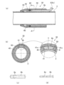
- FIG. 4 is a diagram showing a guide attachment/detachment structure, where (a) is a cross-sectional view along the axial direction, (b) is a cross-sectional view along line AA in FIG.
- FIG. 4 is a diagram showing a base component of the guide attachment/detachment structure, (a) is a plan view, (b) is a cross-sectional view along the axial direction, and (c) is a cross-sectional view along the BB line in FIG. (b).
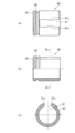
- FIG. 4 is a view showing a fixed part of the guide attachment/detachment structure, (a) is a plan view, (b) is a cross-sectional view along the axial direction, and (c) is a cross-sectional view along the CC line in FIG. (b).
- FIG. 4 is a diagram showing a base component of the guide attachment/detachment structure, (a) is a plan view, (b) is a cross-sectional view along the axial direction, and (c) is a cross-sectional view along the BB line in FIG. (b).
- FIG. 4 is a view showing a fixed part of the guide attachment/detachment structure, (a) is a plan view,
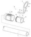
- FIG. 3 is an exploded perspective view of the guide attachment/detachment structure;
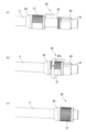
- (a) to (c) are diagrams sequentially showing steps of attaching a fishing line guide to a rod using a guide attachment/detachment structure.
- (a) to (c) are diagrams sequentially showing the process of fixing the fixing part to the base part.
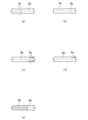
- 4(a) to 4(e) are plan views showing various modifications of the retaining portion formed on the guide leg of the fishing line guide.
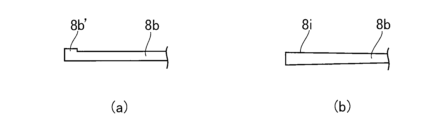
- FIG. 4(a) and 4(b) are side views showing various modifications of the retaining portion formed on the guide leg of the fishing line guide.
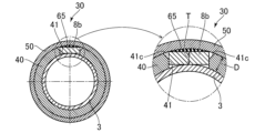
- FIG. Sectional drawing which shows the modification of the fixed component of guide attachment/detachment structure.
- Sectional drawing which shows the modification of the guide leg mounted in guide attachment/detachment structure.
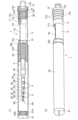
- FIG. 1 and 2 are diagrams showing an embodiment of a fishing rod according to the present invention, FIG. 1(a) being a partial cross-sectional view showing a plurality of rods stored, and FIG. 1(b) showing the storage state.
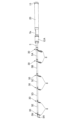
- FIG. 2 is a perspective view of the fishing rod shown in FIG. 1, showing a state of use in which a portion of a plurality of rods are swung out.
- the fishing rods shown in FIGS. 1 and 2 are examples of so-called mobile rods that can be shortened in size when transported. Recently, mobile rods have been attracting attention due to the fact that it is difficult to carry long rods, that long rods cannot be transported due to restrictions by shipping companies, and that shipping costs are rising. there is In this embodiment, such a mobile rod is provided with a detachable structure for a fishing line guide.
- a fishing rod (mobile rod) 1 shown in the figure is constructed in a swing-out type in which a plurality of rods 5A, 5B, 5C, 5D, 5E, . . . It is The number of rods (the number of joints) housed inside the base rod 3 is arbitrary, and N rods (rods 5A to 5N) are sequentially housed in large-diameter rods. , the rod 5N with the smallest diameter is the tip rod (not all the rods to be accommodated are shown in FIGS. 1(a) and 2).
- a fishing line guide 8 for guiding the fishing line is attached to the tip of the main rod 3 and the plurality of rods (the fishing line guide 8A is a top guide).
- FIG. 1 shows the tip of the base rod 3 with the fishing line guide removed from the guide attachment/detachment structure, which will be described later, and FIG. is shown attached.
- a reel seat 9 having a reel leg mounting portion 9a is disposed on the base end side of the base rod 3.
- a fixed hood 11 is provided on the rear end side of the reel seat 9, and a moving hood 12 that moves in the axial direction is provided on the front end side.
- the fixed hood 11 is fixed to the outer peripheral surface of the base end portion of the base rod 3, and has a receiving hole 11a that opens toward the reel leg mounting portion 9a. Further, the moving hood 12 has an opening 12a that opens toward the reel leg mounting portion 9a.
- the moving hood 12 has an operation portion 12A formed with a female screw portion that is screwed into the male screw portion 3A provided on the base rod 3, and the reel leg is placed on the reel leg placing portion 9a.
- the male screw portion 3A to be screwed with the operation portion 12A is formed on the outer peripheral surface of the base rod 3.
- a tubular reel seat is fitted on the outer peripheral surface of the base rod 3, and the reel seat is may be formed on the outer peripheral surface of the
- the rear end of the fixed hood 11 protrudes in the axial direction of the base rod 3.
- a male screw portion 3B is formed on the protruding portion 3a of the base rod 3, and a lower plug (butt plug) 15 is screwed into the protruding portion 3a.
- the lower plug 15 is formed in the shape of a cap, and is formed in a cylindrical shape with an opening (opening 15a) at the rear end.
- a middle and lower plug 16 is fixed to the rear end opening of the base rod 3 by means of a screw-engagement structure or a press-fit structure, and closes the rear end opening of the base rod 3 .
- a rectangular and closed ring-shaped mounting portion 16a is integrally formed on the middle and lower plug 16 toward the rear. It is constructed so as to protrude rearward while being screwed and fixed to the end.
- a cylindrical cover member 20 that functions to prevent projection of a plurality of rods accommodated in the base rod 3 is detachably attached along the axial direction to the base rod 3 .
- the cover member 20 is configured so as to be press-fitted and fixed to the operation portion 12A rotatably disposed on the base rod 3, and extends from the base rod 3 (operation portion 12A) along the axial direction.
- a female threaded portion 20A is formed at the tip of the cover member 20, and a cover body 21 is screwed into this female threaded portion.
- the cover member 20 is taken out from the base rod 3 (operation portion 12A) in the axial direction, and the lid body 21 is removed from the tip of the cover member 20.
- the lower plug 15 is removed from the base rod, and in this state, the female screw portion 20A of the cover member 20 is screwed into the male screw portion 3B of the base rod 3.
- the cover member 20 serves as a grip extending rearward from the fixed hood 11, and can be used with a longer axial length.
- the removed lower plug 15 is press-fitted into this portion, and the rear edge (open end) 20a of the cover member 20 is brought into contact with the annular stepped portion 15b of the lower plug. By attaching it, the opening can be blocked. Further, the removed cover 21 can be integrated with the lower plug 15 by screwing its male threaded portion into the female threaded portion of the lower plug 15 to close the opening 15a of the lower plug 15 .
- the fishing rod 1 of this embodiment is configured to be able to mount both types of reels, a spinning reel and a dual-bearing reel.
- the bearing reel is mounted with the reel seat 9 and the fishing line guide 8 facing upward.
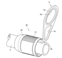
- a fishing line guide attachment/detachment structure (hereinafter referred to as a guide attachment/detachment structure) 30 is provided at the tip of each rod, and the fishing line guide 8 can be attached to and detached from each rod by the guide attachment/detachment structure 30.
- FIG. 1 The above-described fishing line guide 8 includes a guide ring 8a through which the fishing line is inserted, and a guide leg 8b attached to the surface of the base rod (rod) 3.
- the guide leg 8b is attached to the surface of the rod. It is formed so as to extend in the axial direction of the rod.
- the guide leg 8b and the guide ring 8a are connected by a connecting portion 8c, and the guide leg 8b, the guide ring 8a, and the connecting portion 8c are made of, for example, a lightweight metal such as aluminum, a fiber-reinforced resin material, or the like.
- integrally formed by A ring member 8d made of ceramics or the like is press-fitted into the guide ring 8a as needed so as to reduce the sliding resistance of the fishing line.
- the guide attachment/detachment structure 30 is fixed to the surface of the rod (in the drawing, the rod is the base rod 3), and is formed with a recess 41 in which the guide leg 8b of the fishing line guide 8 can be placed. and a cylindrical fixed part 50 which is slidably arranged with respect to the rod 3 and press-fitted so as to cover the base part 40 .
- the base component 40 is integrally formed of metal, resin, wood, hard rubber, etc., and is fixed to the surface of the pole by adhesion or the like.
- the base component should be fixed to the rod, and various fixing means such as screwing, winding a fixing thread and fixing with resin, and winding a tape member can be used.
- the base component may be configured to be detachably fixed to the rod surface.
- the recess 41 formed in the base part 40 is machined so as to correspond to the shape of the guide leg 8b of the fishing line guide mounted therein, and the guide leg 8b is placed in the recess to prevent rattling. Any shape may be used as long as the shape does not occur. Then, with the guide leg 8b placed in the recess 41, the fixed part 50 is slid to attach the fixed part 50 to the base part 40 (attached by sliding in the axial direction and press-fitting). By doing so, the fishing line guide 8 can be fixed to the base rod 3.
- the recesses 41 are preferably formed so that the guide legs 8b are in direct contact with the surface of the rod.
- the recess 41 may have a bottom portion and may be configured such that the bottom portion is interposed between the rear surface of the guide leg on which it is placed and the surface of the rod.
- the fixed part 50 is formed in a tubular shape (cylindrical shape with openings on both sides in the axial direction) of metal, resin, wood, hard rubber, or the like. In addition, it is also possible to form a resin containing carbon fiber with a 3D printer. Unlike molding, the surface has an uneven shape with a large number of carbon fibers protruding, so that the frictional force between the inserted guide leg 8b is improved and the fishing line guide 8 is less likely to come off during actual fishing. becomes possible.
- Such a fixed part 50 is formed to have a larger diameter than the outer diameter of the base rod 3 and is disposed axially slidable along the base rod 3 . Further, by forming uneven portions (knurls or the like) 51 on the surface thereof, it is possible to facilitate the sliding operation and the rotating operation.
- the guide legs 8b are placed in the recesses 41 of the base component 40, and in this state, the fixing component 50 is axially slid and pressed into the base component 40, thereby integrating both.
- the fishing line guide 8 is fixed by the fixing part 50.
- the guide leg 8b is fixed by press-fitting the fixing part 50 into the base part 40 in the axial direction (the male screw part 45 formed on the outer peripheral surface of the rear end side of the base part 40 and the fixing part 45).
- the female screw portion 55 formed on the inner peripheral surface of the rear end side of the part 50 is not screwed together).
- both may be fixed by screwing.
- the fixing component 50 is press-fitted into the base component 40, and then fixed. By rotating the parts, both can be fixed.
- the threaded portion between the two may be provided by press-fitting the fixing part 50 into the base part 40 and fixing this state.
- the fixing part 50 may be integrated with the base part 40 when the fishing line guide 8 is not attached. When both are fixed by screwing in this way, the parts do not move when the rod is housed or carried, so it is difficult for the parts to be scratched or the like.
- the guide leg 8b is placed in the recess 41 of the base component and fixed by the fixing component 50, the rear end of the guide leg 8b and the base component 40 are slightly separated from each other as shown in FIG. 4(a). They may be separated from each other, or they may be in contact with each other.
- the fixing part 50 is press-fitted with the O-ring 60 fitted in the circumferential groove 46, the frictional force between the two increases, making it difficult for the fixing part 50 to come off from the base part 40 (loosening prevention). It is possible to absorb looseness caused by an error or the like.
- the configuration provided with the threaded portion as described above it is possible to prevent the screws from sticking to each other at the time of closing.
- the recess 41 of the base component 40 and the guide leg 8b of the fishing line guide 8 mounted thereon are preferably configured as follows.
- the thickness of the guide leg 8b is T and the depth of the recess 41 of the base component 40 is D, it is preferable to set T ⁇ D.
- the thickness of the guide leg 8b is slightly larger than the shape of the guide leg 8b so as to facilitate the placing operation.
- the shape of the recess 41 is slightly smaller than the shape of the guide leg 8b so that the fixing part is slightly press-fitted.
- the cross-sectional shape of the guide leg 8b is a rectangular shape, the distance between the surface of the base rod 3 and the guide leg 8b, and the inner surface of the fixed part 50 and the guide leg 8b
- the recesses 41 and/or the guide legs 8b of the base component 40 are provided so that when the guide legs 8b are placed in the recesses 41 and the fixing component 50 is press-fitted, the guide legs 8b do not slip out in the axial direction. It is preferable to form a retaining portion to hold the retainer. As shown in FIGS. 4(c) and 4(d), the retaining portion of the present embodiment has notch-like depressions 8e formed on both sides of the guide leg 8b in the width direction, and as shown in FIG. , and protrusions 41c that fit into the recesses 8e are formed on both inner walls of the recess 41 in the width direction.
- FIG. 8( a ) the guide leg 8 b of the fishing line guide 8 is placed in the recess 41 of the base component 40 fixed to the base rod 3 .
- the fixing member 50 is slid and press-fitted into the base component 40, thereby completing the fixing operation of the fishing line guide.
- the guide legs 8b are simply placed in the recesses 41, and the guide legs 8b and the connecting portions 8c can be pinched and press-fitted as in the conventional art. Therefore, no load is applied to the guide leg 8b and the connecting portion 8c, and the guide leg is prevented from being damaged, bent or broken when the fishing line guide is attached or detached.
- the guide leg 8b and the connecting portion 8c no load is applied to the guide leg 8b and the connecting portion 8c, and the guide leg is prevented from being damaged, bent or broken when the fishing line guide is attached or detached.
- the fixing member 50 is slid onto the base component 40, and the fixing component 50 is tightened by the threaded portions formed on both. Since the fixing part 50 is fixed to the base part 40, it is difficult to damage it during actual fishing or carrying.
- FIGS. 10(a) to 10(e) are plan views (in which the right side of the drawing is drawn) showing modifications of the guide leg 8b.
- the recess 8e is formed in the guide leg 8b to constitute the retaining portion of the fishing line guide.
- the taper 8f may be formed so as to widen toward the distal end side.
- the depression 8e may be formed on one of both side surfaces.
- the high friction portion 8g may be formed by roughening the surface of the guide leg 8b or attaching a friction member.
- FIGS. 11(a) and 11(b) are side views (the direction in which the right side of the drawing is drawn) showing a modification of the guide leg 8b.
- a thick portion 8b' may be formed on the tip side, or as shown in (b), a taper 8i may be formed on the upper surface so as to gradually thicken toward the tip.
- the guide leg 8b is simply placed in the recess 41 of the base component 40, it is possible to make it difficult for the fixing member 50 to come off when the fixing member 50 is attached by properly deforming the shape of the guide leg 8b. is.
- the shape of the recess 41 of the base component 40 can also be changed appropriately according to the shape of the guide leg 8b.
- FIG. 12A and 12B are diagrams showing a modification of the fixing component 50.
- FIG. In this modification where T is the thickness of the guide leg 8b and D is the depth of the recess 41 of the base component 40, T ⁇ D is set.
- T is the thickness of the guide leg 8b and D is the depth of the recess 41 of the base component 40
- T ⁇ D is set.
- the elastic member 65 is attached to the inner surface of the fixed part 50 so as to contact the surface of the guide leg 8b placed in the recess 41.
- FIG. Even with such a configuration, it is possible to prevent the fishing line guide 8 from coming off, and to prevent rattling or loosening of the fishing line guide.
- FIG. 13 is a cross-sectional view showing a modification of the guide leg mounted on the guide attachment/detachment structure.
- the back surface of the guide leg 8b is formed flat as in the above-described embodiment, the surface of the base rod 3 and the back surface of the guide leg come into contact with each other, and the guide is stabilized when the guide is fixed. may not. Therefore, as shown in FIG. 13, by forming a concave portion 8h on the back surface of the guide leg 8b, the surface of the base rod 3 and the back surface of the guide leg come into contact with each other at two points (the contact portion is indicated by 8h').
- the fishing line guide is fixed, it can be easily stabilized.
- the shape and formation position of such a concave portion are arbitrary, and can be appropriately deformed as long as it is configured to contact with the surface of the pole at a plurality of points.
- the present invention is not limited to the above-described embodiments, and can be modified in various ways.
- the retainer for the fishing line guide 8 can be appropriately deformed, such as by pressing a flexible member.
- the fishing line guide 8 may have a plurality of guide legs.
- the above-described guide attachment/detachment structure 30 may be provided at a plurality of locations on one rod, and can be applied to various fishing rods other than mobile rods.
Landscapes
- Life Sciences & Earth Sciences (AREA)
- Environmental Sciences (AREA)
- Marine Sciences & Fisheries (AREA)
- Animal Husbandry (AREA)
- Biodiversity & Conservation Biology (AREA)
- Fishing Rods (AREA)
Abstract
Description
実際の使用時には、カバー部材20を元竿杆3(操作部12A)から軸方向に取り出すと共に、蓋体21をカバー部材20の先端から取り外す。また、下栓15を元竿杆から取り外し、この状態で、カバー部材20の雌螺子部20Aを元竿杆3の雄螺子部3Bに螺合する。これにより、カバー部材20が固定フード11から後方に延びるグリップとなり、軸方向長さを長くして使用することができる。
上記した釣糸ガイド8は、釣糸が挿通されるガイドリング8aと、元竿杆(竿杆)3の表面に取り付けられるガイド脚8bとを備えた構成となっており、ガイド脚8bは、装着される竿杆の軸方向に延出するよう形成されている。この場合、ガイド脚8bとガイドリング8aとの間は、連結部8cによって連結されており、ガイド脚8b、ガイドリング8a、連結部8cは、例えば、アルミ等の軽量金属や繊維強化樹脂材等によって一体形成されている。なお、ガイドリング8aの部分には、釣糸の摺動抵抗を減らすように、必要に応じてセラミックス等で形成されたリング部材8dが圧入されている。
このような固定部品50は、元竿杆3の外径よりも大径に形成されており、元竿杆3に沿って軸方向に摺動可能に配設される。また、その表面に凹凸部(ローレット等)51を形成しておくことで、摺動操作、及び、回転操作を行い易くすることができる。
このような円周溝46にOリング60を嵌入した状態で固定部品50を圧入すると、両者の間の摩擦力が高まって固定部品50を土台部品40から抜け難く(緩み止め)できると共に、寸法誤差等によって生じるガタ付を吸収することが可能となる。また、上記したような螺合部を設けた構成では、仕舞時の螺子同士の固着を防止することが可能となる。
なお、土台部品40が固い材質であれば、凹所41の形状は、ガイド脚8bの形状よりも多少大きくして、載置操作がし易いように構成することが好ましいが、土台部品40が柔軟な材質であれば、凹所41の形状は、ガイド脚8bの形状よりも多少小さくして、固定部品を圧入気味にすることが好ましい。
本実施形態の抜け止め部は、図4(c)(d)に示すように、ガイド脚8bの幅方向両側に、切欠状の窪み8eを形成すると共に、図5(a)に示すように、凹所41の幅方向の両内壁に、窪み8eと嵌合する突起41cを形成することで構成されている。
図8(a)に示すように、釣糸ガイド8のガイド脚8bを、元竿杆3に固定されている土台部品40の凹所41に載置する。この場合、凹所41の形状とガイド脚8bの形状は略一致しているため、釣糸ガイド8が脱落等することはない。
この状態で、図8(b)(c)に示すように、固定部材50を摺動させて土台部品40に圧入することで、釣糸ガイドの固定操作が完了する。
図10(a)~(e)は、それぞれガイド脚8bの変形例を示した平面図(図面の右側が抜ける方向)である。上記したように、ガイド脚8bに窪み8eを形成することで、釣糸ガイドの抜け止め部を構成したが、このような抜け止め部の構成については種々、変形することが可能である。例えば、(a)に示すように、先端側に向けて拡幅するようにテーパ8fを形成しても良い。また、(b)に示すように、窪み8eは、両側面の一方の側面に形成したものであっても良い。また、(c)(d)に示すように、窪み8eを形成する位置や形成個数については適宜変形することが可能である。また、(e)に示すように、ガイド脚8bの表面を粗面化したり、摩擦部材を被着する等、高摩擦部8gを形成しても良い。
この変形例では、ガイド脚8bの肉厚をT、土台部品40の凹所41の深さをDとした場合、T<Dに設定している。このような構成では、ガイド脚8bが外れ易くなるため、固定部品50の内面に、凹所41に載置されたガイド脚8bの表面に当接するように弾性部材65を被着している。
このような構成であっても、釣糸ガイド8の抜けを防止できると共に、釣糸ガイドのガタ付きや緩み等を防止することが可能である。
上記した実施形態のように、ガイド脚8bの裏面が平面に形成されていると、元竿杆3の表面とガイド脚の裏面が1点当たりとなって、ガイドを固定した際にガイドが安定しない可能性がある。そこで、図13に示すように、ガイド脚8bの裏面に凹部8hを形成することで、元竿杆3の表面とガイド脚の裏面が2点当たり(当接部を8h´で示す)となり、釣糸ガイドを固定した際に、安定し易くすることが可能となる。
このような凹部については、その形状や形成位置は任意であり、竿杆の表面との間で複数点で接触する構成であれば、適宜、変形することが可能である。
上記した実施形態において、釣糸ガイド8の抜け止めは、柔軟部材を圧入するなど、適宜、変形することが可能である。また、釣糸ガイド8のガイド脚は、複数形成されていても良い。更に、上記したガイド着脱構造30は、1つの竿杆に複数個所、設けられていても良く、モバイルロッド以外の各種の釣竿に適用することが可能である。
3 元竿杆(竿杆)
8 釣糸ガイド
8a ガイドリング
8b ガイド脚
30 ガイド着脱構造
40 土台部品
41 凹所
50 固定部品
Claims (9)
- 釣糸が挿通される釣糸ガイドのガイド脚を竿杆表面に対して着脱可能にするガイド着脱構造を備えた釣竿において、
前記ガイド着脱構造は、竿杆表面に対して固定され、釣糸ガイドのガイド脚を載置可能な凹所が形成された土台部品と、前記竿杆に対して摺動可能に配設され、前記土台部品を覆うように圧入される筒状の固定部品と、を有し、
前記釣糸ガイドのガイド脚は、前記土台部品の凹所に載置され、固定部品を摺動させて前記土台部品に圧入することで前記竿杆に固定されることを特徴とする釣竿。 - 前記土台部品は、竿杆表面に対して着脱可能に固定されることを特徴とする請求項1に記載の釣竿。
- 前記固定部品と土台部品は、螺合によって固定可能であることを特徴とする請求項1又は2に記載の釣竿。
- 前記土台部品の凹所、及び/又は、前記ガイド脚には、前記凹所にガイド脚を載置して前記固定部品を圧入した際、前記ガイド脚が軸方向に抜けないようにする抜け止め部が形成されていることを特徴とする請求項1から3のいずれか1項に記載の釣竿。
- 前記脚部の肉厚をT、前記土台部品の凹所の深さをDとした場合、T≧Dに設定したことを特徴とする請求項1から4のいずれか1項に記載の釣竿。
- 前記固定部品の内面には、前記凹所に載置されるガイド脚の表面に当接する弾性部材が被着されていることを特徴とする請求項1から5のいずれか1項に記載の釣竿。
- 前記土台部品の表面には、前記固定部品の内面と密着するOリングが嵌合される円周溝が形成されていることを特徴とする請求項1から6のいずれか1項に記載の釣竿。
- 前記土台部品の凹所は、載置される前記ガイド脚を、竿杆表面に直接接触させるように形成されていることを特徴とする請求項1から7のいずれか1項に記載の釣竿。
- 釣糸が挿通される釣糸ガイドのガイド脚を釣竿の竿杆表面に対して着脱可能にするガイド着脱構造において、
前記ガイド着脱構造は、竿杆表面に対して固定可能であり、釣糸ガイドのガイド脚を載置可能な凹所が形成された土台部品と、前記竿杆に対して摺動可能であり、前記土台部品を覆うように圧入される筒状の固定部品と、を有し、
前記土台部品と固定部品は、前記釣糸ガイドのガイド脚を、前記土台部品の凹所に載置した状態で、前記固定部品を前記土台部品に圧入することで竿杆に固定状態に保持させることを特徴とするガイド着脱構造。
Priority Applications (4)
| Application Number | Priority Date | Filing Date | Title |
|---|---|---|---|
| KR1020247017345A KR20240090934A (ko) | 2021-10-28 | 2022-10-14 | 낚싯대 및 낚싯줄 가이드의 착탈 구조 |
| EP22886732.1A EP4424155A4 (en) | 2021-10-28 | 2022-10-14 | FISHING ROD AND FISHING LINE GUIDE ATTACHMENT/DETACHMENT STRUCTURE |
| CN202280082244.1A CN118382358B (zh) | 2021-10-28 | 2022-10-14 | 钓竿以及钓线引导件的装卸构造 |
| US18/711,433 US12550876B2 (en) | 2021-10-28 | 2022-10-14 | Fishing rod and attachment/detachment structure for fishing line guide |
Applications Claiming Priority (2)
| Application Number | Priority Date | Filing Date | Title |
|---|---|---|---|
| JP2021-176573 | 2021-10-28 | ||
| JP2021176573A JP7667725B2 (ja) | 2021-10-28 | 2021-10-28 | 釣竿、及び、釣糸ガイドの着脱構造 |
Publications (1)
| Publication Number | Publication Date |
|---|---|
| WO2023074403A1 true WO2023074403A1 (ja) | 2023-05-04 |
Family
ID=86157965
Family Applications (1)
| Application Number | Title | Priority Date | Filing Date |
|---|---|---|---|
| PCT/JP2022/038298 Ceased WO2023074403A1 (ja) | 2021-10-28 | 2022-10-14 | 釣竿、及び、釣糸ガイドの着脱構造 |
Country Status (6)
| Country | Link |
|---|---|
| US (1) | US12550876B2 (ja) |
| EP (1) | EP4424155A4 (ja) |
| JP (1) | JP7667725B2 (ja) |
| KR (1) | KR20240090934A (ja) |
| CN (1) | CN118382358B (ja) |
| WO (1) | WO2023074403A1 (ja) |
Cited By (1)
| Publication number | Priority date | Publication date | Assignee | Title |
|---|---|---|---|---|
| US20260206733A1 (en) * | 2024-11-18 | 2026-07-23 | Shawn Lee Dykes | Replacement fishing eyes |
Families Citing this family (1)
| Publication number | Priority date | Publication date | Assignee | Title |
|---|---|---|---|---|
| JP2024090403A (ja) * | 2022-12-23 | 2024-07-04 | 株式会社シマノ | 釣竿および釣糸ガイド |
Citations (5)
| Publication number | Priority date | Publication date | Assignee | Title |
|---|---|---|---|---|
| JPH0365130A (ja) | 1989-07-21 | 1991-03-20 | Reglass Spa | 交換可能な釣糸誘導装置を備えた釣竿、およびこのような釣竿の使用方法 |
| JPH0482961U (ja) * | 1990-11-29 | 1992-07-20 | ||
| JP2013202004A (ja) * | 2012-03-29 | 2013-10-07 | Globeride Inc | 釣竿及び物品取付構造 |
| CN108835057A (zh) * | 2018-08-01 | 2018-11-20 | 朱之鸿 | 一种具有可拆式导线环的鱼竿 |
| JP2021141887A (ja) * | 2020-03-10 | 2021-09-24 | 富士工業株式会社 | 釣り糸ガイド及び釣り竿 |
Family Cites Families (19)
| Publication number | Priority date | Publication date | Assignee | Title |
|---|---|---|---|---|
| GB190914137A (en) * | 1909-06-16 | 1910-04-21 | Hardy Brothers Alnwick Ltd | Improved Means applicable for use in Attaching Reels to Fishing-rods. |
| GB196216A (en) * | 1922-07-31 | 1923-04-19 | John James Hardy | Improved means for attaching reels to fishing rods |
| US2543881A (en) * | 1948-10-11 | 1951-03-06 | Umphlette Charles Leonard | Floating reel seat for fishing rods |
| FR1183906A (fr) * | 1957-10-04 | 1959-07-15 | Mepps | Dispositif de fixation d'un porte-moulinet sur la poignée d'une canne à pêche |
| US3614143A (en) * | 1970-07-13 | 1971-10-19 | Milton J Stevens | Ferrule unit for fishing rods and method of construction |
| US4050179A (en) * | 1976-03-31 | 1977-09-27 | Johnson Frank W | Rod butt with integral reel seat |
| FR2665333A1 (fr) * | 1990-08-06 | 1992-02-07 | Garbolino Sa Ets | Dispositif pour la fixation d'anneaux guide-fil sur les cannes a peche telescopiques. |
| JP2726964B2 (ja) * | 1992-04-28 | 1998-03-11 | 富士工業株式会社 | 釣竿用リールシート |
| JP2547945B2 (ja) * | 1993-07-09 | 1996-10-30 | 株式会社シマノ | 中通し竿 |
| JP3014345U (ja) * | 1995-02-03 | 1995-08-08 | 株式会社余天 | リール釣竿用ガイド |
| KR20000020744U (ko) * | 1999-05-13 | 2000-12-15 | 이광애 | 낚시대용 리일 고정장치 |
| US6381898B1 (en) * | 2000-09-18 | 2002-05-07 | Tsung-Seng Lee | Reel-seat assembly |
| JP4418767B2 (ja) * | 2005-03-29 | 2010-02-24 | グローブライド株式会社 | 釣竿の穂先 |
| KR100781735B1 (ko) * | 2006-12-20 | 2007-12-03 | 기간산업 주식회사 | 낚싯대용 릴 시트 |
| JP5414361B2 (ja) * | 2009-05-27 | 2014-02-12 | 株式会社シマノ | 筒状リールシート |
| JP2012029607A (ja) * | 2010-07-29 | 2012-02-16 | Globeride Inc | 釣竿 |
| EP2933093B1 (en) * | 2014-03-26 | 2018-10-24 | Globeride, Inc. | Reel leg fixing apparatus and method of fabricating the hood portion of the reel leg fixing apparatus |
| US20210000095A1 (en) * | 2019-07-02 | 2021-01-07 | Pure Fishing, Inc. | Enclosure for an electronic device in a fishing rod |
| JP7448374B2 (ja) * | 2020-02-26 | 2024-03-12 | 株式会社シマノ | 固定補助具及び釣竿 |
-
2021
- 2021-10-28 JP JP2021176573A patent/JP7667725B2/ja active Active
-
2022
- 2022-10-14 WO PCT/JP2022/038298 patent/WO2023074403A1/ja not_active Ceased
- 2022-10-14 CN CN202280082244.1A patent/CN118382358B/zh active Active
- 2022-10-14 EP EP22886732.1A patent/EP4424155A4/en active Pending
- 2022-10-14 KR KR1020247017345A patent/KR20240090934A/ko active Pending
- 2022-10-14 US US18/711,433 patent/US12550876B2/en active Active
Patent Citations (5)
| Publication number | Priority date | Publication date | Assignee | Title |
|---|---|---|---|---|
| JPH0365130A (ja) | 1989-07-21 | 1991-03-20 | Reglass Spa | 交換可能な釣糸誘導装置を備えた釣竿、およびこのような釣竿の使用方法 |
| JPH0482961U (ja) * | 1990-11-29 | 1992-07-20 | ||
| JP2013202004A (ja) * | 2012-03-29 | 2013-10-07 | Globeride Inc | 釣竿及び物品取付構造 |
| CN108835057A (zh) * | 2018-08-01 | 2018-11-20 | 朱之鸿 | 一种具有可拆式导线环的鱼竿 |
| JP2021141887A (ja) * | 2020-03-10 | 2021-09-24 | 富士工業株式会社 | 釣り糸ガイド及び釣り竿 |
Non-Patent Citations (1)
| Title |
|---|
| See also references of EP4424155A4 |
Cited By (1)
| Publication number | Priority date | Publication date | Assignee | Title |
|---|---|---|---|---|
| US20260206733A1 (en) * | 2024-11-18 | 2026-07-23 | Shawn Lee Dykes | Replacement fishing eyes |
Also Published As
| Publication number | Publication date |
|---|---|
| KR20240090934A (ko) | 2024-06-21 |
| CN118382358B (zh) | 2026-03-24 |
| CN118382358A (zh) | 2024-07-23 |
| US20250017186A1 (en) | 2025-01-16 |
| EP4424155A4 (en) | 2025-11-05 |
| JP2023066073A (ja) | 2023-05-15 |
| JP7667725B2 (ja) | 2025-04-23 |
| EP4424155A1 (en) | 2024-09-04 |
| US12550876B2 (en) | 2026-02-17 |
Similar Documents
| Publication | Publication Date | Title |
|---|---|---|
| JP2023066073A (ja) | 釣竿、及び、釣糸ガイドの着脱構造 | |
| KR100230638B1 (ko) | 낚싯대용 릴시트 | |
| US20030145509A1 (en) | Fishing rod | |
| JP7117987B2 (ja) | 釣竿用リールシートのナット及び釣竿用リールシート並びに釣竿 | |
| KR102062710B1 (ko) | 릴 시트용 팜 레스트, 릴 시트, 및 낚싯대 | |
| JP6839879B2 (ja) | リールシート及びこれを備える釣り竿 | |
| CN211657212U (zh) | 卷线器固定装置 | |
| US6712300B2 (en) | Methods and apparatus for a quick-change spool system | |
| CN101897324A (zh) | 渔线轮座 | |
| JP7094735B2 (ja) | リールシート | |
| JP7149032B2 (ja) | リールシート及びサポートグリップ | |
| JP7489897B2 (ja) | 釣竿 | |
| US4651945A (en) | Removable spool for a fishing rod reel | |
| JP7252912B2 (ja) | 振出式の釣竿セット | |
| JP4498761B2 (ja) | 釣竿 | |
| JP7715626B2 (ja) | リールシート | |
| JP7307012B2 (ja) | 振出式の釣竿 | |
| JP7600533B2 (ja) | 液体貯留タンクのキャップ、液体貯留タンク | |
| JP2017175927A (ja) | リールシート及び当該リールシートを備える釣竿 | |
| JP6898221B2 (ja) | 釣竿用リールシート及び釣竿 | |
| JP7773823B1 (ja) | リール取付構造 | |
| JP2025099495A (ja) | エンドグリップ | |
| JPH0686988U (ja) | 両頭筆記具 | |
| JP2593528Y2 (ja) | 釣り竿のリールシート | |
| JP2520423Y2 (ja) | 振出し竿 |
Legal Events
| Date | Code | Title | Description |
|---|---|---|---|
| 121 | Ep: the epo has been informed by wipo that ep was designated in this application |
Ref document number: 22886732 Country of ref document: EP Kind code of ref document: A1 |
|
| ENP | Entry into the national phase |
Ref document number: 20247017345 Country of ref document: KR Kind code of ref document: A |
|
| WWE | Wipo information: entry into national phase |
Ref document number: 2022886732 Country of ref document: EP |
|
| NENP | Non-entry into the national phase |
Ref country code: DE |
|
| ENP | Entry into the national phase |
Ref document number: 2022886732 Country of ref document: EP Effective date: 20240528 |
|
| WWE | Wipo information: entry into national phase |
Ref document number: 202280082244.1 Country of ref document: CN |
|
| WWE | Wipo information: entry into national phase |
Ref document number: 18711433 Country of ref document: US |
|
| WWG | Wipo information: grant in national office |
Ref document number: 18711433 Country of ref document: US |