WO2023074907A1 - 地図作成装置、地図作成方法、及び地図作成プログラム - Google Patents
地図作成装置、地図作成方法、及び地図作成プログラム Download PDFInfo
- Publication number
- WO2023074907A1 WO2023074907A1 PCT/JP2022/040838 JP2022040838W WO2023074907A1 WO 2023074907 A1 WO2023074907 A1 WO 2023074907A1 JP 2022040838 W JP2022040838 W JP 2022040838W WO 2023074907 A1 WO2023074907 A1 WO 2023074907A1
- Authority
- WO
- WIPO (PCT)
- Prior art keywords
- vehicle
- camera
- amount
- change
- images
- Prior art date
- Legal status (The legal status is an assumption and is not a legal conclusion. Google has not performed a legal analysis and makes no representation as to the accuracy of the status listed.)
- Ceased
Links
Images


Classifications
-
- G—PHYSICS
- G06—COMPUTING OR CALCULATING; COUNTING
- G06T—IMAGE DATA PROCESSING OR GENERATION, IN GENERAL
- G06T7/00—Image analysis
- G06T7/70—Determining position or orientation of objects or cameras
-
- G—PHYSICS
- G01—MEASURING; TESTING
- G01C—MEASURING DISTANCES, LEVELS OR BEARINGS; SURVEYING; NAVIGATION; GYROSCOPIC INSTRUMENTS; PHOTOGRAMMETRY OR VIDEOGRAMMETRY
- G01C11/00—Photogrammetry or videogrammetry, e.g. stereogrammetry; Photographic surveying
- G01C11/04—Interpretation of pictures
- G01C11/30—Interpretation of pictures by triangulation
-
- G—PHYSICS
- G01—MEASURING; TESTING
- G01C—MEASURING DISTANCES, LEVELS OR BEARINGS; SURVEYING; NAVIGATION; GYROSCOPIC INSTRUMENTS; PHOTOGRAMMETRY OR VIDEOGRAMMETRY
- G01C21/00—Navigation; Navigational instruments not provided for in groups G01C1/00 - G01C19/00
- G01C21/38—Electronic maps specially adapted for navigation; Updating thereof
- G01C21/3804—Creation or updating of map data
- G01C21/3833—Creation or updating of map data characterised by the source of data
- G01C21/3848—Data obtained from both position sensors and additional sensors
-
- G—PHYSICS
- G06—COMPUTING OR CALCULATING; COUNTING
- G06T—IMAGE DATA PROCESSING OR GENERATION, IN GENERAL
- G06T7/00—Image analysis
- G06T7/50—Depth or shape recovery
- G06T7/55—Depth or shape recovery from multiple images
- G06T7/579—Depth or shape recovery from multiple images from motion
-
- G—PHYSICS
- G06—COMPUTING OR CALCULATING; COUNTING
- G06T—IMAGE DATA PROCESSING OR GENERATION, IN GENERAL
- G06T7/00—Image analysis
- G06T7/70—Determining position or orientation of objects or cameras
- G06T7/73—Determining position or orientation of objects or cameras using feature-based methods
Definitions
- the present disclosure relates to a map creation device, a map creation method, and a map creation program.
- Non-Patent Document 1 there is a technology for capturing the surrounding environment with a camera mounted on a vehicle and estimating the position and orientation of the vehicle from the captured images (for example, Steven Lovegrove, Andrew J. Davison and Javier Ibanez-Guzman, "Accurate Visual Odometry from a Rear Parking Camera", Intelligent Vehicles Symposium, 2011. Hereinafter referred to as "Non-Patent Document 1").
- Non-Patent Document 1 According to the technique described in Non-Patent Document 1, as shown in FIG. 9, multiple images as shown in FIG. 10 are obtained when two different locations are photographed by a camera installed at the rear of the vehicle. A road surface region is extracted from these multiple images, and the optimal value of the homography matrix between the multiple images is obtained by performing repeated calculations based on the brightness of the extracted road surface region.
- An ESM (Efficient Second Order Minimization) algorithm is used as an algorithm for iterative calculation. Then, the amount of change in position and the amount of change in attitude of the vehicle are calculated from the optimum values of the homography matrix.
- Non-Patent Document 1 requires a large amount of repeated calculations when obtaining the optimum value of the homography matrix, and cannot be reduced in cost. For this reason, it is desired to reduce the amount of calculation of repeated calculations.
- the present disclosure has been made in view of the above circumstances. It is an object of the present invention to provide a map creation device, a map creation method, and a map creation program.
- a map creation device includes an image acquisition unit that acquires a plurality of images of different points photographed from an in-vehicle camera that is mounted on a vehicle and that photographs the surroundings of the vehicle.
- an odometry information calculation unit that calculates odometry information indicating the amount of movement of the vehicle; an initial value calculation unit that calculates an initial value of a homography matrix between the plurality of images from the odometry information of the vehicle; and an optimum value calculation unit for repeatedly calculating an optimum value of the homography matrix from the luminance value of each pixel included in the road surface area designated for the plurality of images; and decomposing the optimum value.
- a camera position/orientation calculation unit for calculating the amount of change in camera position and the amount of change in camera orientation of the vehicle-mounted camera; and a three-dimensional position calculator that calculates the three-dimensional position of the point.
- the map creation device is the map creation device according to the first aspect, wherein the camera position/orientation calculation unit decomposes the optimum values to determine the normal direction of the road surface viewed from the vehicle-mounted camera.
- An estimated value of the road surface normal vector which is a vector, is further calculated, and an error represented by an angle between the estimated value of the road surface normal vector and the value of the road surface normal vector obtained in advance by calibrating the vehicle-mounted camera. is less than a threshold, the use determining unit determines to use the amount of change in the camera position and the amount of change in the camera orientation.
- map creation device is the map creation device according to the second aspect, wherein when the error is equal to or greater than the threshold value, the usage determination unit It is determined that the amount of change is not used.
- a map creation method acquires a plurality of images of different points captured from an on-vehicle camera that is mounted on a vehicle and captures images of the surroundings of the vehicle, calculating odometry information indicating the amount of movement of the vehicle, calculating an initial value of a homography matrix between the plurality of images from the odometry information of the vehicle, and specifying the initial value and the plurality of images;
- Optimal values of the homography matrix are calculated by iterative calculation from the brightness values of each pixel included in the road surface area obtained, and the optimal values are decomposed to determine the amount of change in the camera position and the camera orientation of the vehicle-mounted camera. The amount of change is calculated, and the three-dimensional positions of the feature points in the plurality of images are calculated from the amount of change in the camera position and the amount of change in the camera orientation.
- a map creation program acquires a plurality of images of different points captured from an on-vehicle camera that is mounted on a vehicle and captures the surroundings of the vehicle, calculating odometry information indicating the amount of movement of the vehicle, calculating an initial value of a homography matrix between the plurality of images from the odometry information of the vehicle, and specifying the initial value and the plurality of images;
- Optimal values of the homography matrix are calculated by iterative calculation from the brightness values of each pixel included in the road surface area obtained, and the optimal values are decomposed to determine the amount of change in the camera position and the camera orientation of the vehicle-mounted camera.
- a computer is caused to calculate the amount of change, and to calculate the three-dimensional positions of feature points in the plurality of images from the amount of change in the camera position and the amount of change in the camera orientation.
- FIG. 5 is a diagram showing an example of the amount of change in the position of the vehicle and the amount of change in the yaw angle of the vehicle according to the embodiment; It is a figure which shows an example of the positional relationship of the vehicle-mounted camera which concerns on embodiment, and a road surface.
- FIG. 4 is a diagram showing an example of corresponding road surface areas among a plurality of images according to the embodiment, and showing an image before the vehicle moves;
- FIG. 5 is a diagram showing an example of corresponding road surface areas among a plurality of images according to the embodiment, and showing an image after the vehicle has moved; It is a flowchart which shows an example of the flow of a process by the map creation program which concerns on embodiment. 7 is a flowchart showing an example of the flow of homography matrix optimum value calculation processing according to the embodiment; FIG. 4 is a diagram showing an example of an image and a tracking area before movement; It is a figure where it uses for description of a prior art. It is a figure where it uses for description of a prior art.
- the map creation device relates to map initialization when creating a point cloud map in the framework of Visual SLAM (Simultaneous Localization and Mapping) technology using an in-vehicle camera.
- SLAM Simultaneous Localization and Mapping
- FIG. 1 is a diagram showing an example of the configuration of a map creation system 100 according to this embodiment.
- the map creation system 100 includes a map creation device 10, a wheel speed sensor 20, a steering angle sensor 21, and an in-vehicle camera 22.
- the in-vehicle camera 22 is mounted on the vehicle and photographs the surroundings of the vehicle.
- the in-vehicle camera 22 may be installed in a state in which the road surface can be photographed, and the installation location in the vehicle is not particularly limited.
- the in-vehicle camera 22 is, for example, a monocular camera, but is not limited to this, and may be a stereo camera or the like.
- the in-vehicle camera 22 is a monocular camera provided on the upper part of the vehicle, etc., and photographs the surrounding areas such as the front and rear of the vehicle.
- the vehicle-mounted camera 22 is provided, for example, near the center in the vehicle width direction, and is arranged such that the optical axis of the vehicle-mounted camera 22 faces slightly downward from the horizontal direction.
- the vehicle-mounted camera 22 is communicably connected to the map creation device 10 and sends captured images to the map creation device 10 .
- the wheel speed sensor 20 detects the wheel speed of the four wheels of the vehicle.
- the wheel speed sensor 20 sends the detected wheel speed to the mapping device 10 .
- Wheel encoders are usually used for the wheel speed sensors 20, but motor encoders may be used in vehicles such as hybrid vehicles that are equipped with motors. Motor encoders are desirable because they have higher detection accuracy than wheel encoders.
- the steering angle sensor 21 detects the steering angle of the vehicle.
- the steering angle sensor 21 sends the detected steering angle to the mapping device 10 .
- the map creation device 10 calculates the initial values of homography matrices between a plurality of images from vehicle odometry information, and uses the calculated initial values to calculate the optimum values of the homography matrices. As a result, it is possible to reduce the amount of repetitive calculations.
- the map creation device 10 according to the present embodiment is intended for in-vehicle use. In the case of in-vehicle use, the processing capacity of resources such as processors and memories is relatively low. Less load on resources and greater efficiency.
- the map creation device 10 may be implemented as part of an ECU (Electronic Control Unit), which is a vehicle control computer, or may be implemented as an in-vehicle computer separate from the ECU.
- ECU Electronic Control Unit
- the map creation device 10 may be implemented as part of an ECU (Electronic Control Unit), which is a vehicle control computer, or may be implemented as an in-vehicle computer separate from the ECU.
- the map creation device 10 includes a CPU (Central Processing Unit) 11, a ROM (Read Only Memory) 12, a RAM (Random Access Memory) 13, an input/output interface (I/O) 14, a storage unit 15, an external and an interface (external I/F) 16 .
- CPU Central Processing Unit
- ROM Read Only Memory
- RAM Random Access Memory
- I/O input/output interface
- storage unit 15, an external and an interface (external I/F) 16 .
- the CPU 11, ROM 12, RAM 13, and I/O 14 are each connected via a bus.
- Functional units including a storage unit 15 and an external I/F 16 are connected to the I/O 14 .
- Each of these functional units can communicate with the CPU 11 via the I/O 14 .
- a control unit is configured by the CPU 11, ROM 12, RAM 13, and I/O 14.
- the control unit may be configured as a sub-control unit that controls part of the operation of the map creation device 10, or may be configured as a part of the main control unit that controls the overall operation of the map creation device 10.
- An integrated circuit such as an LSI (Large Scale Integration) or an IC (Integrated Circuit) chipset is used for part or all of each block of the control unit.
- An individual circuit may be used for each of the above blocks, or a circuit in which a part or all of them are integrated may be used.
- the blocks may be provided integrally, or some of the blocks may be provided separately. Moreover, in each of the above blocks, a part thereof may be separately provided.
- a dedicated circuit or a general-purpose processor may be used for integration of the control unit, not limited to an LSI.
- the storage unit 15 for example, an HDD (Hard Disk Drive), an SSD (Solid State Drive), a flash memory, or the like is used.
- the storage unit 15 stores a map creation program 15A according to this embodiment. Note that the map creation program 15A may be stored in the ROM 12. FIG.
- the map creation program 15A may be pre-installed in the map creation device 10, for example.
- the map creation program 15A may be implemented by storing it in a non-volatile storage medium or distributing it via a network and installing it in the map creation device 10 as appropriate.
- Examples of non-volatile storage media include CD-ROM (Compact Disc Read Only Memory), magneto-optical disc, HDD, DVD-ROM (Digital Versatile Disc Read Only Memory), flash memory, memory card, etc. be.
- the external I/F 16 is an interface for communicably connecting with each of the wheel speed sensor 20, the steering angle sensor 21, and the vehicle-mounted camera 22.
- the CPU 11 of the map creation device 10 writes the map creation program 15A stored in the storage unit 15 into the RAM 13 and executes it, thereby functioning as each unit shown in FIG.
- FIG. 2 is a block diagram showing an example of the functional configuration of the map creation device 10 according to this embodiment.
- the CPU 11 of the map creation device 10 includes an image acquisition unit 11A, a sensor information acquisition unit 11B, an odometry information calculation unit 11C, an initial value calculation unit 11D, an optimum value calculation unit 11E, a camera It functions as a position/orientation calculation unit 11F, a usage determination unit 11G, and a three-dimensional position calculation unit 11H.
- the image acquisition unit 11A acquires a plurality of images from the vehicle-mounted camera 22.
- the image acquisition unit 11A sends the multiple acquired images to the optimum value calculation unit 11E.
- the plurality of images are, for example, images captured at two different locations.
- the sensor information acquisition unit 11B acquires the wheel speed detected by the wheel speed sensor 20 and the steering angle detected by the steering angle sensor 21.
- the sensor information acquisition section 11B sends the acquired wheel speed and steering angle to the odometry information calculation section 11C.
- the odometry information calculation unit 11C calculates odometry information indicating the amount of movement of the vehicle based on the wheel speed and steering angle from the sensor information acquisition unit 11B. Specifically, the odometry information calculator 11C calculates the traveling distance of the vehicle based on the wheel speed, and calculates the turning radius of the vehicle based on the steering angle.
- FIG. 3 is a diagram showing an example of the amount of change in the position of the vehicle and the amount of change in the yaw angle of the vehicle according to this embodiment.
- the odometry information calculator 11C calculates the amount of position change ( ⁇ X v , ⁇ Y v ) of the vehicle (reference point P1) in the vehicle coordinate system and the yaw Angular change amount ⁇ v is calculated.
- the odometry information calculation unit 11C sends the calculated position change amount ( ⁇ X v , ⁇ Y v ) and yaw angle change amount ⁇ v to the initial value calculation unit 11D as vehicle odometry information.
- the initial value calculator 11D calculates initial values of homography matrices between a plurality of images based on the vehicle odometry information from the odometry information calculator 11C. Homography means projecting a plane onto another plane using projective transformation. Specifically, the initial value calculator 11D calculates a translational vector t c representing a positional change of the vehicle-mounted camera 22 from the positional variation ( ⁇ X v , ⁇ Y v ), and calculates the vehicle-mounted camera 22 from the yaw angle variation ⁇ v . Compute the rotation matrix R c representing the 22 pose changes.
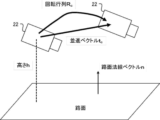
- FIG. 4 is a diagram showing an example of the positional relationship between the vehicle-mounted camera 22 and the road surface according to this embodiment.
- the in-vehicle camera 22 is installed at a height h from the road surface.
- the above-described position change amount ( ⁇ X v , ⁇ Y v ) and yaw angle change amount ⁇ v are calculated as odometry information.
- the translation vector t c is calculated from the position change amount ( ⁇ X v , ⁇ Y v )
- the rotation matrix R c is calculated from the yaw angle change amount ⁇ v .
- a road surface normal vector n is a vector in the normal direction of the road surface viewed from the vehicle-mounted camera 22 and has a magnitude of one.
- the initial value calculator 11D calculates the initial value G0 of the homography matrix using the following equation (1).
- K indicates an internal parameter matrix of the vehicle-mounted camera 22
- Rc indicates a rotation matrix
- tc indicates the translation vector
- nT indicates the transposed matrix of the value n of the road surface normal vector
- h indicates the installation height of the vehicle-mounted camera 22 from the road surface.
- the initial value calculator 11D sends the initial value G0 calculated by the above equation (1) to the optimum value calculator 11E.
- the optimum value calculation unit 11E calculates the homography matrix from the initial value from the initial value calculation unit 11D and the luminance value of each pixel included in the road surface area designated for the plurality of images from the image acquisition unit 11A.
- the optimum value is calculated by iterative calculation. Specifically, as an example, as shown in FIG. 5, a road surface area is designated in an image, and an optimum value GOPT of the homography matrix is calculated using an ESM algorithm, which is an example of repeated calculation.
- FIGS. 5A and 5B are diagrams showing examples of corresponding road surface regions between a plurality of images according to this embodiment.
- FIG. 5A shows the image before the vehicle moves
- FIG. 5B shows the image after the vehicle moves.
- a road area R1 is designated in the image before the vehicle moves shown in FIG. 5A.
- the image after vehicle movement shown in FIG. 5B includes a road surface region R2 calculated with the initial value G0 of the homography matrix and a road surface region R3 calculated with the optimum value G_OPT of the homography matrix.
- the initial value G0 of the homography matrix between images at two points is calculated from the odometry information of the vehicle, and the calculated initial value G0 is used to obtain the optimum value G of the homography matrix.
- Calculate OPT That is, by calculating the initial value G 0 of the homography matrix from the odometry information of the vehicle, the initial value G 0 is set to a value closer to the optimum value G OPT than when the odometry information is not used. Therefore, the number of iterations of iterative calculation can be reduced.
- a specific method for calculating the optimum value GOPT of the homography matrix will be described later.
- the camera position/orientation calculation unit 11F decomposes the optimum value from the optimum value calculation unit 11E to calculate the amount of change in the camera position and the amount of change in the camera orientation of the vehicle-mounted camera 22 .
- the amount of change in the camera position is represented as an estimated value test of the translation vector, and the amount of change in the camera pose is represented as an estimated value R est of the rotation matrix.
- the camera position/orientation calculation unit 11F also decomposes the optimum value from the optimum value calculation unit 11E to calculate an estimated value of the road surface normal vector.
- the optimal value G_OPT is decomposed as shown in Equation (2) below.
- K indicates an internal parameter matrix of the vehicle-mounted camera 22
- Rest indicates a rotation matrix (estimated value) representing the amount of change in camera posture.
- test indicates the translation vector (estimated value) representing the amount of change in the camera position
- nest T indicates the transposed matrix of the estimated value nest of the road surface normal vector
- h indicates the installation height of the in-vehicle camera 22 from the road surface.
- the usage determination unit 11G determines that the amount of change in camera position and the amount of change in camera orientation are not to be used in subsequent processes. If it is not used, the optimum values of the homography matrix are re-determined from images taken at two different locations.
- the threshold value can be set to an appropriate value within a range from 0 degrees to 5 degrees.
- the usage determination unit 11G is not essential, and the configuration may be such that the usage determination unit 11G is not included. In this case, the amount of change in the camera position and the amount of change in the camera orientation calculated by the camera position/orientation calculator 11F are used as they are in the post-process.
- the three-dimensional position calculation unit 11H calculates three-dimensional positions of feature points in a plurality of images from the amount of change in the camera position and the amount of change in the camera posture when the use determination unit 11G determines to use the image. Specifically, the three-dimensional position calculation unit 11H uses the position of the feature point associated between the images of the two different points, the amount of change in the camera position, and the amount of change in the camera attitude to determine the three positions of the feature points based on the principle of triangulation. Calculate dimensional positions.
- FIG. 6 is a flowchart showing an example of the flow of processing by the map creation program 15A according to this embodiment.
- the CPU 11 starts the map creation program 15A and executes the following steps.
- step S101 of FIG. 6 the CPU 11 acquires a plurality of images shot at two different points from the vehicle-mounted camera 22, as shown in FIG. 5 above, as an example.
- step S102 the CPU 11 acquires the wheel speed from the wheel speed sensor 20 and the steering angle from the steering angle sensor 21 as sensor information.
- step S103 the CPU 11 calculates odometry information indicating the amount of movement of the vehicle based on the wheel speed and the steering angle acquired in step S102, as shown in FIG. 3 described above. Specifically, the CPU 11 calculates the traveling distance of the vehicle based on the wheel speed, and calculates the turning radius of the vehicle based on the steering angle. Then, the amount of change in position ( ⁇ X v , ⁇ Y v ) and the amount of change in yaw angle ⁇ v of the vehicle (reference point P1) in the vehicle coordinate system are calculated from the traveling distance and turning radius of the vehicle.
- step S104 the CPU 11 calculates initial values of homography matrices between a plurality of images based on the vehicle odometry information calculated in step S103. Specifically, the CPU 11 calculates the translational vector t c representing the positional change of the vehicle-mounted camera 22 from the positional change amount ( ⁇ X v , ⁇ Y v ) as shown in FIG. A rotation matrix Rc representing a change in the attitude of the vehicle-mounted camera 22 is calculated from the amount of change ⁇ v , and the initial value G0 of the homography matrix is calculated using the above equation (1).
- step S105 the CPU 11 calculates the initial values calculated in step S104 and each pixel included in the road surface area designated for the plurality of images acquired in step S101. , the optimum value of the homography matrix is calculated by iterative calculation.
- the homography matrix optimum value calculation processing in step S105 will be specifically described with reference to FIGS. 7 and 8. FIG.
- FIG. 7 is a flowchart showing an example of the flow of homography matrix optimum value calculation processing according to the present embodiment, and is a subroutine of step S105 of FIG. Also, FIG. 8 is a diagram showing an example of the image I * before movement and the tracking area.
- step S111 of FIG. 7 the CPU 11 designates a tracking area (synonymous with the road surface area) for the image I * before movement as shown in FIG. Compute the matrices J W , J G , and .
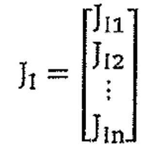
- the luminance gradient matrix J I* is calculated using the following equation from the luminance of each pixel in the tracking area in the image I * before movement (values from 0 to 255).
- JI*ui indicates the horizontal luminance gradient of the i-th pixel
- JI *vi indicates the vertical luminance gradient of the i-th pixel.
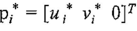
- the Jacobian matrix JW is calculated by the following equation from the coordinates of each pixel in the tracking area in the image I * before movement.
- [A i ] v is a 9-by-1 vector permuted row by row.
- step S112 the CPU 11 substitutes an initial value G0 for the estimated value G ⁇ ( ⁇ is just above G, hereinafter the same) of the homography matrix, and 1 for the number of iterations nite .
- step S113 the CPU 11 calculates the brightness gradient matrix JI of the tracking area in the image I after movement.
- the coordinates in the image I after movement are calculated by the following formula.
- the brightness gradient matrix J I is calculated from the brightness of each pixel in the tracking area in the image I after movement by the following equation.
- J Iui indicates the horizontal luminance gradient of the i-th pixel
- J Ivi indicates the vertical luminance gradient of the i-th pixel.
- step S114 the CPU 11 calculates the parameter x of the homography matrix (vector of 8 rows and 1 column).
- the parameter x is calculated by the following formula.
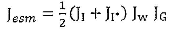
- J esm is a Jacobian matrix and is calculated by the following equation.
- y is the luminance difference vector and is expressed by the following equation.
- yi is calculated from the luminance Ii of the i-th pixel after movement and the luminance Ii * of the i-th pixel before movement by the following equation.
- step S115 the CPU 11 updates the estimated value G ⁇ of the homography matrix using the following equation.
- step S116 the CPU 11 determines whether or not the termination condition is satisfied, that is, whether or not iteration is necessary. If the termination condition is satisfied, that is, if iteration (repetition) is determined to be unnecessary (in the case of affirmative determination), the process proceeds to step S117. If yes), return to step S113 and repeat the process.
- y curr is expressed by the following equation.
- n max (eg, 100) be the upper limit number of iterations
- ⁇ (eg, 10 ⁇ 5 ) be the threshold for convergence determination.
- n ite 1
- the root mean square y prev of the previous luminance difference is substituted by the root mean square y curr of the current luminance difference, 1 is added to the number of iterations n ite , and the process returns to step S113.
- step S117 In the case of 1 ⁇ n ite ⁇ n max , if y prev ⁇ y curr > ⁇ , it is determined that the convergence has not occurred, and the root mean square y prev of the previous luminance difference is added to the root mean square y curr is substituted, 1 is added to the number of iterations nite , and the process returns to step S113. On the other hand, if y prev ⁇ y curr ⁇ , it is determined that convergence has occurred, and the process proceeds to step S117.
- step S117 the CPU 11 adopts the estimated value G ⁇ of the homography matrix as the optimum value GOPT , and returns to step S106 in FIG.
- step S106 the CPU 11 decomposes the optimum value GOPT calculated in step S105 using the above equation (2) as an example, and calculates the amount of change in the camera position and the amount of change in the camera attitude. , and an estimated value of the road surface normal vector.
- step S107 the CPU 11 determines whether or not the amount of change in the camera position and the amount of change in the camera orientation can be used. If it is determined that it can be used (in the case of affirmative determination), the process proceeds to step S108, and if it is determined that it cannot be used (in the case of a negative determination), the process returns to step S101 and the process is repeated. Specifically, when the error represented by the angle between the estimated value n est of the road surface normal vector and the value n of the road surface normal vector obtained in advance by calibrating the in-vehicle camera 22 is less than the threshold value, the CPU 11 First, it is determined that the amount of change in the camera position and the amount of change in the camera orientation are to be used in the post-process.
- the error is equal to or greater than the threshold, it is determined that the amount of change in the camera position and the amount of change in the camera orientation are not to be used in the post-process. If it is not used, the optimum values of the homography matrix are re-determined from images taken at two different locations.
- step S108 the CPU 11 calculates the three-dimensional positions of feature points in a plurality of images from the amount of change in camera position and the amount of change in camera posture, and terminates a series of processing by the map creation program 15A. Specifically, the CPU 11 calculates the three-dimensional position of the feature point based on the principle of triangulation from the position of the feature point associated between the images of the two different points, the amount of change in the camera position, and the amount of change in the camera orientation. .
- the present embodiment by calculating the initial values of the homography matrix from the odometry information of the vehicle, it is possible to repeatedly start the calculation from a value close to the optimum value of the homography matrix. Therefore, the number of repetitions of iterative calculations is reduced.
- the error in the homography matrix increases, so the error in the road surface normal obtained from the homography matrix may also increase.
- the error of the road surface normal is obtained by comparison with the road surface normal obtained from the camera installation direction. If the error of the road surface normal is large, it can be determined that the determined amount of change in camera position and amount of change in camera attitude cannot be used, and the homography matrix can be re-determined from images taken at two different points.
- processor refers to a processor in a broad sense, and includes general-purpose processors (eg, CPU: Central Processing Unit, etc.) and dedicated processors (eg, GPU: Graphics Processing Unit, ASIC: Application Specific Integrated Circuit, FPGA: Field Programmable Gate Array, programmable logic device, etc.).
- general-purpose processors eg, CPU: Central Processing Unit, etc.
- dedicated processors eg, GPU: Graphics Processing Unit, ASIC: Application Specific Integrated Circuit
- FPGA Field Programmable Gate Array, programmable logic device, etc.
- processors in each of the above embodiments may be performed not only by one processor, but also by the cooperation of a plurality of physically separated processors. Also, the order of each operation of the processor is not limited to the order described in each of the above embodiments, and may be changed as appropriate.
- the map creation device has been described above as an example.
- the embodiment may be in the form of a program for causing a computer to execute the function of each unit provided in the map creation device.
- Embodiments may be in the form of a computer-readable non-transitory storage medium storing these programs.
- the configuration of the map creation device described in the above embodiment is an example, and may be changed according to circumstances within the scope of the gist.
- Embodiments may be implemented by, for example, a hardware configuration or a combination of hardware and software configurations.
Landscapes
- Engineering & Computer Science (AREA)
- Physics & Mathematics (AREA)
- General Physics & Mathematics (AREA)
- Remote Sensing (AREA)
- Computer Vision & Pattern Recognition (AREA)
- Theoretical Computer Science (AREA)
- Radar, Positioning & Navigation (AREA)
- Multimedia (AREA)
- Automation & Control Theory (AREA)
- Image Analysis (AREA)
- Image Processing (AREA)
Abstract
Description


Claims (5)
- 車両に搭載され、かつ、前記車両の周辺を撮影する車載カメラから、異なる地点を撮影した複数の画像を取得する画像取得部と、
前記車両の移動量を示すオドメトリ情報を算出するオドメトリ情報算出部と、
前記車両のオドメトリ情報から、前記複数の画像間のホモグラフィ行列の初期値を算出する初期値算出部と、
前記初期値、及び、前記複数の画像に対して指定された路面領域に含まれる各画素の輝度値から、前記ホモグラフィ行列の最適値を繰り返し計算により算出する最適値算出部と、
前記最適値を分解して、前記車載カメラについてのカメラ位置の変化量及びカメラ姿勢の変化量を算出するカメラ位置姿勢算出部と、
前記カメラ位置の変化量及び前記カメラ姿勢の変化量から、前記複数の画像における特徴点の3次元位置を算出する3次元位置算出部と、
を備えた地図作成装置。 - 前記カメラ位置姿勢算出部は、前記最適値を分解して、前記車載カメラから見た路面の法線方向のベクトルである路面法線ベクトルの推定値を更に算出し、
前記路面法線ベクトルの推定値と予め前記車載カメラのキャリブレーションにより求めた路面法線ベクトルの値との間の角度で表される誤差が閾値未満である場合に、前記カメラ位置の変化量及び前記カメラ姿勢の変化量を利用すると判定する利用判定部を更に備えた
請求項1に記載の地図作成装置。 - 前記利用判定部は、前記誤差が前記閾値以上である場合に、前記カメラ位置の変化量及び前記カメラ姿勢の変化量を利用しないと判定する
請求項2に記載の地図作成装置。 - 車両に搭載され、かつ、前記車両の周辺を撮影する車載カメラから、異なる地点を撮影した複数の画像を取得し、
前記車両の移動量を示すオドメトリ情報を算出し、
前記車両のオドメトリ情報から、前記複数の画像間のホモグラフィ行列の初期値を算出し、
前記初期値、及び、前記複数の画像に対して指定された路面領域に含まれる各画素の輝度値から、前記ホモグラフィ行列の最適値を繰り返し計算により算出し、
前記最適値を分解して、前記車載カメラについてのカメラ位置の変化量及びカメラ姿勢の変化量を算出し、
前記カメラ位置の変化量及び前記カメラ姿勢の変化量から、前記複数の画像における特徴点の3次元位置を算出する、
地図作成方法。 - 車両に搭載され、かつ、前記車両の周辺を撮影する車載カメラから、異なる地点を撮影した複数の画像を取得し、
前記車両の移動量を示すオドメトリ情報を算出し、
前記車両のオドメトリ情報から、前記複数の画像間のホモグラフィ行列の初期値を算出し、
前記初期値、及び、前記複数の画像に対して指定された路面領域に含まれる各画素の輝度値から、前記ホモグラフィ行列の最適値を繰り返し計算により算出し、
前記最適値を分解して、前記車載カメラについてのカメラ位置の変化量及びカメラ姿勢の変化量を算出し、
前記カメラ位置の変化量及び前記カメラ姿勢の変化量から、前記複数の画像における特徴点の3次元位置を算出することを、
コンピュータに実行させるための地図作成プログラム。
Priority Applications (3)
| Application Number | Priority Date | Filing Date | Title |
|---|---|---|---|
| US18/691,587 US20240386598A1 (en) | 2021-10-29 | 2022-10-31 | Map creation device, map creation method, and map creation program |
| EP22887232.1A EP4425430A4 (en) | 2021-10-29 | 2022-10-31 | CARD GENERATING DEVICE, CARD GENERATING METHOD AND CARD GENERATING PROGRAM |
| CN202280063240.9A CN117957569A (zh) | 2021-10-29 | 2022-10-31 | 地图制作装置、地图制作方法以及地图制作程序 |
Applications Claiming Priority (2)
| Application Number | Priority Date | Filing Date | Title |
|---|---|---|---|
| JP2021178338A JP7714436B2 (ja) | 2021-10-29 | 2021-10-29 | 地図作成装置、地図作成方法、及び地図作成プログラム |
| JP2021-178338 | 2021-10-29 |
Publications (1)
| Publication Number | Publication Date |
|---|---|
| WO2023074907A1 true WO2023074907A1 (ja) | 2023-05-04 |
Family
ID=86158106
Family Applications (1)
| Application Number | Title | Priority Date | Filing Date |
|---|---|---|---|
| PCT/JP2022/040838 Ceased WO2023074907A1 (ja) | 2021-10-29 | 2022-10-31 | 地図作成装置、地図作成方法、及び地図作成プログラム |
Country Status (5)
| Country | Link |
|---|---|
| US (1) | US20240386598A1 (ja) |
| EP (1) | EP4425430A4 (ja) |
| JP (1) | JP7714436B2 (ja) |
| CN (1) | CN117957569A (ja) |
| WO (1) | WO2023074907A1 (ja) |
Cited By (1)
| Publication number | Priority date | Publication date | Assignee | Title |
|---|---|---|---|---|
| WO2025204954A1 (ja) * | 2024-03-29 | 2025-10-02 | オムロン株式会社 | オドメトリパラメータ較正装置、方法、及びプログラム |
Families Citing this family (2)
| Publication number | Priority date | Publication date | Assignee | Title |
|---|---|---|---|---|
| KR20230158335A (ko) * | 2022-05-11 | 2023-11-20 | 현대자동차주식회사 | 차량 및 그 제어 방법 |
| US12482128B2 (en) * | 2022-08-17 | 2025-11-25 | Gm Cruise Holdings Llc | Identifying stability of an object based on surface normal vectors |
Citations (2)
| Publication number | Priority date | Publication date | Assignee | Title |
|---|---|---|---|---|
| JP2015100065A (ja) * | 2013-11-20 | 2015-05-28 | キヤノン株式会社 | 画像処理装置、その制御方法、および制御プログラム、並びに撮像装置 |
| JP2021178338A (ja) | 2020-05-12 | 2021-11-18 | 株式会社ディスコ | レーザー加工方法 |
-
2021
- 2021-10-29 JP JP2021178338A patent/JP7714436B2/ja active Active
-
2022
- 2022-10-31 EP EP22887232.1A patent/EP4425430A4/en active Pending
- 2022-10-31 CN CN202280063240.9A patent/CN117957569A/zh active Pending
- 2022-10-31 WO PCT/JP2022/040838 patent/WO2023074907A1/ja not_active Ceased
- 2022-10-31 US US18/691,587 patent/US20240386598A1/en active Pending
Patent Citations (2)
| Publication number | Priority date | Publication date | Assignee | Title |
|---|---|---|---|---|
| JP2015100065A (ja) * | 2013-11-20 | 2015-05-28 | キヤノン株式会社 | 画像処理装置、その制御方法、および制御プログラム、並びに撮像装置 |
| JP2021178338A (ja) | 2020-05-12 | 2021-11-18 | 株式会社ディスコ | レーザー加工方法 |
Non-Patent Citations (3)
| Title |
|---|
| See also references of EP4425430A4 |
| STEVEN LOVEGROVE ; ANDREW J. DAVISON ; JAVIER IBANEZ-GUZMAN: "Accurate visual odometry from a rear parking camera", INTELLIGENT VEHICLES SYMPOSIUM (IV), 2011 IEEE, 5 June 2011 (2011-06-05), pages 788 - 793, XP031999056, ISBN: 978-1-4577-0890-9, DOI: 10.1109/IVS.2011.5940546 * |
| STEVEN LOVEGROVEANDREW J. DAVISONJAVIER IBANEZ-GUZMAN: "Accurate Visual Odometry from a Rear Parking Camera", INTELLIGENT VEHICLES SYMPOSIUM, 2011 |
Cited By (1)
| Publication number | Priority date | Publication date | Assignee | Title |
|---|---|---|---|---|
| WO2025204954A1 (ja) * | 2024-03-29 | 2025-10-02 | オムロン株式会社 | オドメトリパラメータ較正装置、方法、及びプログラム |
Also Published As
| Publication number | Publication date |
|---|---|
| EP4425430A4 (en) | 2025-02-12 |
| EP4425430A1 (en) | 2024-09-04 |
| JP2023067265A (ja) | 2023-05-16 |
| JP7714436B2 (ja) | 2025-07-29 |
| US20240386598A1 (en) | 2024-11-21 |
| CN117957569A (zh) | 2024-04-30 |
Similar Documents
| Publication | Publication Date | Title |
|---|---|---|
| CN112183241B (zh) | 基于单目图像的目标检测方法和装置 | |
| CN110264520B (zh) | 车载传感器与车辆位姿关系标定方法、装置、设备和介质 | |
| WO2023074907A1 (ja) | 地図作成装置、地図作成方法、及び地図作成プログラム | |
| CN110119698B (zh) | 用于确定对象状态的方法、装置、设备和存储介质 | |
| WO2021093240A1 (en) | Method and system for camera-lidar calibration | |
| CN107111879B (zh) | 通过全景环视图像估计车辆自身运动的方法和设备 | |
| CN114217665B (zh) | 一种相机和激光雷达时间同步方法、装置及存储介质 | |
| CN114144809A (zh) | 通过摄像机进行交通工具环境建模 | |
| JP6003673B2 (ja) | 3次元位置推定装置、車両制御装置、および3次元位置推定方法 | |
| CN108845335A (zh) | 一种基于图像和导航信息的无人机地面目标定位方法 | |
| CN107636679A (zh) | 一种障碍物检测方法及装置 | |
| CN112219225A (zh) | 定位方法、系统及可移动平台 | |
| JP7408236B2 (ja) | 位置推定方法及び位置推定装置 | |
| CN116092050B (zh) | 机动车障碍物检测方法、装置及计算机可读存储介质 | |
| CN118149797B (zh) | 栅格地图构建方法、装置、计算机设备及存储介质 | |
| JP6724834B2 (ja) | 表示装置の制御方法および表示装置 | |
| CN115222815A (zh) | 障碍物距离检测方法、装置、计算机设备和存储介质 | |
| WO2022202915A1 (ja) | 自律走行車及び自律走行車の自己位置推定方法 | |
| JP7643428B2 (ja) | 位置推定システム、位置推定方法、及びプログラム | |
| WO2022133986A1 (en) | Accuracy estimation method and system | |
| CN114648576A (zh) | 一种目标车辆的定位方法、装置以及系统 | |
| CN121254246B (zh) | 激光雷达外参的标定方法、设备、可读介质及程序产品 | |
| KR102878417B1 (ko) | 3차원 메쉬 생성 장치 및 방법 | |
| JP7564742B2 (ja) | 情報処理装置及び情報処理方法 | |
| US20260024226A1 (en) | Information processing device, information processing method, and computer-readable medium |
Legal Events
| Date | Code | Title | Description |
|---|---|---|---|
| 121 | Ep: the epo has been informed by wipo that ep was designated in this application |
Ref document number: 22887232 Country of ref document: EP Kind code of ref document: A1 |
|
| WWE | Wipo information: entry into national phase |
Ref document number: 18691587 Country of ref document: US |
|
| WWE | Wipo information: entry into national phase |
Ref document number: 202280063240.9 Country of ref document: CN |
|
| WWE | Wipo information: entry into national phase |
Ref document number: 2022887232 Country of ref document: EP |
|
| NENP | Non-entry into the national phase |
Ref country code: DE |
|
| ENP | Entry into the national phase |
Ref document number: 2022887232 Country of ref document: EP Effective date: 20240529 |