WO2023074908A1 - 方向性電磁鋼板の製造方法および方向性電磁鋼板 - Google Patents
方向性電磁鋼板の製造方法および方向性電磁鋼板 Download PDFInfo
- Publication number
- WO2023074908A1 WO2023074908A1 PCT/JP2022/040839 JP2022040839W WO2023074908A1 WO 2023074908 A1 WO2023074908 A1 WO 2023074908A1 JP 2022040839 W JP2022040839 W JP 2022040839W WO 2023074908 A1 WO2023074908 A1 WO 2023074908A1
- Authority
- WO
- WIPO (PCT)
- Prior art keywords
- mass
- sheet
- grain
- hot
- slab
- Prior art date
- Legal status (The legal status is an assumption and is not a legal conclusion. Google has not performed a legal analysis and makes no representation as to the accuracy of the status listed.)
- Ceased
Links
Images


Classifications
-
- H—ELECTRICITY
- H01—ELECTRIC ELEMENTS
- H01F—MAGNETS; INDUCTANCES; TRANSFORMERS; SELECTION OF MATERIALS FOR THEIR MAGNETIC PROPERTIES
- H01F1/00—Magnets or magnetic bodies characterised by the magnetic materials therefor; Selection of materials for their magnetic properties
- H01F1/01—Magnets or magnetic bodies characterised by the magnetic materials therefor; Selection of materials for their magnetic properties of inorganic materials
- H01F1/03—Magnets or magnetic bodies characterised by the magnetic materials therefor; Selection of materials for their magnetic properties of inorganic materials characterised by their coercivity
- H01F1/12—Magnets or magnetic bodies characterised by the magnetic materials therefor; Selection of materials for their magnetic properties of inorganic materials characterised by their coercivity of soft-magnetic materials
- H01F1/14—Magnets or magnetic bodies characterised by the magnetic materials therefor; Selection of materials for their magnetic properties of inorganic materials characterised by their coercivity of soft-magnetic materials metals or alloys
- H01F1/147—Alloys characterised by their composition
-
- C—CHEMISTRY; METALLURGY
- C22—METALLURGY; FERROUS OR NON-FERROUS ALLOYS; TREATMENT OF ALLOYS OR NON-FERROUS METALS
- C22C—ALLOYS
- C22C38/00—Ferrous alloys, e.g. steel alloys
- C22C38/02—Ferrous alloys, e.g. steel alloys containing silicon
-
- C—CHEMISTRY; METALLURGY
- C21—METALLURGY OF IRON
- C21D—MODIFYING THE PHYSICAL STRUCTURE OF FERROUS METALS; GENERAL DEVICES FOR HEAT TREATMENT OF FERROUS OR NON-FERROUS METALS OR ALLOYS; MAKING METAL MALLEABLE, e.g. BY DECARBURISATION OR TEMPERING
- C21D1/00—General methods or devices for heat treatment, e.g. annealing, hardening, quenching or tempering
- C21D1/34—Methods of heating
- C21D1/42—Induction heating
-
- C—CHEMISTRY; METALLURGY
- C21—METALLURGY OF IRON
- C21D—MODIFYING THE PHYSICAL STRUCTURE OF FERROUS METALS; GENERAL DEVICES FOR HEAT TREATMENT OF FERROUS OR NON-FERROUS METALS OR ALLOYS; MAKING METAL MALLEABLE, e.g. BY DECARBURISATION OR TEMPERING
- C21D6/00—Heat treatment of ferrous alloys
- C21D6/008—Heat treatment of ferrous alloys containing Si
-
- C—CHEMISTRY; METALLURGY
- C21—METALLURGY OF IRON
- C21D—MODIFYING THE PHYSICAL STRUCTURE OF FERROUS METALS; GENERAL DEVICES FOR HEAT TREATMENT OF FERROUS OR NON-FERROUS METALS OR ALLOYS; MAKING METAL MALLEABLE, e.g. BY DECARBURISATION OR TEMPERING
- C21D8/00—Modifying the physical properties of ferrous metals or ferrous alloys by deformation combined with, or followed by, heat treatment
- C21D8/12—Modifying the physical properties of ferrous metals or ferrous alloys by deformation combined with, or followed by, heat treatment during manufacturing of articles with special electromagnetic properties
- C21D8/1216—Modifying the physical properties of ferrous metals or ferrous alloys by deformation combined with, or followed by, heat treatment during manufacturing of articles with special electromagnetic properties characterised by the working steps
- C21D8/1222—Hot rolling
-
- C—CHEMISTRY; METALLURGY
- C21—METALLURGY OF IRON
- C21D—MODIFYING THE PHYSICAL STRUCTURE OF FERROUS METALS; GENERAL DEVICES FOR HEAT TREATMENT OF FERROUS OR NON-FERROUS METALS OR ALLOYS; MAKING METAL MALLEABLE, e.g. BY DECARBURISATION OR TEMPERING
- C21D8/00—Modifying the physical properties of ferrous metals or ferrous alloys by deformation combined with, or followed by, heat treatment
- C21D8/12—Modifying the physical properties of ferrous metals or ferrous alloys by deformation combined with, or followed by, heat treatment during manufacturing of articles with special electromagnetic properties
- C21D8/1216—Modifying the physical properties of ferrous metals or ferrous alloys by deformation combined with, or followed by, heat treatment during manufacturing of articles with special electromagnetic properties characterised by the working steps
- C21D8/1233—Cold rolling
-
- C—CHEMISTRY; METALLURGY
- C21—METALLURGY OF IRON
- C21D—MODIFYING THE PHYSICAL STRUCTURE OF FERROUS METALS; GENERAL DEVICES FOR HEAT TREATMENT OF FERROUS OR NON-FERROUS METALS OR ALLOYS; MAKING METAL MALLEABLE, e.g. BY DECARBURISATION OR TEMPERING
- C21D8/00—Modifying the physical properties of ferrous metals or ferrous alloys by deformation combined with, or followed by, heat treatment
- C21D8/12—Modifying the physical properties of ferrous metals or ferrous alloys by deformation combined with, or followed by, heat treatment during manufacturing of articles with special electromagnetic properties
- C21D8/1244—Modifying the physical properties of ferrous metals or ferrous alloys by deformation combined with, or followed by, heat treatment during manufacturing of articles with special electromagnetic properties characterised by the heat treatment
- C21D8/1261—Modifying the physical properties of ferrous metals or ferrous alloys by deformation combined with, or followed by, heat treatment during manufacturing of articles with special electromagnetic properties characterised by the heat treatment following hot rolling
-
- C—CHEMISTRY; METALLURGY
- C21—METALLURGY OF IRON
- C21D—MODIFYING THE PHYSICAL STRUCTURE OF FERROUS METALS; GENERAL DEVICES FOR HEAT TREATMENT OF FERROUS OR NON-FERROUS METALS OR ALLOYS; MAKING METAL MALLEABLE, e.g. BY DECARBURISATION OR TEMPERING
- C21D8/00—Modifying the physical properties of ferrous metals or ferrous alloys by deformation combined with, or followed by, heat treatment
- C21D8/12—Modifying the physical properties of ferrous metals or ferrous alloys by deformation combined with, or followed by, heat treatment during manufacturing of articles with special electromagnetic properties
- C21D8/1244—Modifying the physical properties of ferrous metals or ferrous alloys by deformation combined with, or followed by, heat treatment during manufacturing of articles with special electromagnetic properties characterised by the heat treatment
- C21D8/1272—Final recrystallisation annealing
-
- C—CHEMISTRY; METALLURGY
- C21—METALLURGY OF IRON
- C21D—MODIFYING THE PHYSICAL STRUCTURE OF FERROUS METALS; GENERAL DEVICES FOR HEAT TREATMENT OF FERROUS OR NON-FERROUS METALS OR ALLOYS; MAKING METAL MALLEABLE, e.g. BY DECARBURISATION OR TEMPERING
- C21D8/00—Modifying the physical properties of ferrous metals or ferrous alloys by deformation combined with, or followed by, heat treatment
- C21D8/12—Modifying the physical properties of ferrous metals or ferrous alloys by deformation combined with, or followed by, heat treatment during manufacturing of articles with special electromagnetic properties
- C21D8/1277—Modifying the physical properties of ferrous metals or ferrous alloys by deformation combined with, or followed by, heat treatment during manufacturing of articles with special electromagnetic properties involving a particular surface treatment
- C21D8/1283—Application of a separating or insulating coating
-
- C—CHEMISTRY; METALLURGY
- C21—METALLURGY OF IRON
- C21D—MODIFYING THE PHYSICAL STRUCTURE OF FERROUS METALS; GENERAL DEVICES FOR HEAT TREATMENT OF FERROUS OR NON-FERROUS METALS OR ALLOYS; MAKING METAL MALLEABLE, e.g. BY DECARBURISATION OR TEMPERING
- C21D9/00—Heat treatment, e.g. annealing, hardening, quenching or tempering, adapted for particular articles; Furnaces therefor
- C21D9/46—Heat treatment, e.g. annealing, hardening, quenching or tempering, adapted for particular articles; Furnaces therefor for sheet metals
-
- C—CHEMISTRY; METALLURGY
- C22—METALLURGY; FERROUS OR NON-FERROUS ALLOYS; TREATMENT OF ALLOYS OR NON-FERROUS METALS
- C22C—ALLOYS
- C22C38/00—Ferrous alloys, e.g. steel alloys
- C22C38/001—Ferrous alloys, e.g. steel alloys containing N
-
- C—CHEMISTRY; METALLURGY
- C22—METALLURGY; FERROUS OR NON-FERROUS ALLOYS; TREATMENT OF ALLOYS OR NON-FERROUS METALS
- C22C—ALLOYS
- C22C38/00—Ferrous alloys, e.g. steel alloys
- C22C38/002—Ferrous alloys, e.g. steel alloys containing In, Mg, or other elements not provided for in one single group C22C38/001 - C22C38/60
-
- C—CHEMISTRY; METALLURGY
- C22—METALLURGY; FERROUS OR NON-FERROUS ALLOYS; TREATMENT OF ALLOYS OR NON-FERROUS METALS
- C22C—ALLOYS
- C22C38/00—Ferrous alloys, e.g. steel alloys
- C22C38/04—Ferrous alloys, e.g. steel alloys containing manganese
-
- C—CHEMISTRY; METALLURGY
- C22—METALLURGY; FERROUS OR NON-FERROUS ALLOYS; TREATMENT OF ALLOYS OR NON-FERROUS METALS
- C22C—ALLOYS
- C22C38/00—Ferrous alloys, e.g. steel alloys
- C22C38/06—Ferrous alloys, e.g. steel alloys containing aluminium
-
- C—CHEMISTRY; METALLURGY
- C22—METALLURGY; FERROUS OR NON-FERROUS ALLOYS; TREATMENT OF ALLOYS OR NON-FERROUS METALS
- C22C—ALLOYS
- C22C38/00—Ferrous alloys, e.g. steel alloys
- C22C38/60—Ferrous alloys, e.g. steel alloys containing lead, selenium, tellurium, or antimony, or more than 0.04% by weight of sulfur
-
- H—ELECTRICITY
- H01—ELECTRIC ELEMENTS
- H01F—MAGNETS; INDUCTANCES; TRANSFORMERS; SELECTION OF MATERIALS FOR THEIR MAGNETIC PROPERTIES
- H01F1/00—Magnets or magnetic bodies characterised by the magnetic materials therefor; Selection of materials for their magnetic properties
- H01F1/01—Magnets or magnetic bodies characterised by the magnetic materials therefor; Selection of materials for their magnetic properties of inorganic materials
- H01F1/03—Magnets or magnetic bodies characterised by the magnetic materials therefor; Selection of materials for their magnetic properties of inorganic materials characterised by their coercivity
- H01F1/12—Magnets or magnetic bodies characterised by the magnetic materials therefor; Selection of materials for their magnetic properties of inorganic materials characterised by their coercivity of soft-magnetic materials
- H01F1/14—Magnets or magnetic bodies characterised by the magnetic materials therefor; Selection of materials for their magnetic properties of inorganic materials characterised by their coercivity of soft-magnetic materials metals or alloys
- H01F1/16—Magnets or magnetic bodies characterised by the magnetic materials therefor; Selection of materials for their magnetic properties of inorganic materials characterised by their coercivity of soft-magnetic materials metals or alloys in the form of sheets
-
- C—CHEMISTRY; METALLURGY
- C21—METALLURGY OF IRON
- C21D—MODIFYING THE PHYSICAL STRUCTURE OF FERROUS METALS; GENERAL DEVICES FOR HEAT TREATMENT OF FERROUS OR NON-FERROUS METALS OR ALLOYS; MAKING METAL MALLEABLE, e.g. BY DECARBURISATION OR TEMPERING
- C21D2201/00—Treatment for obtaining particular effects
- C21D2201/05—Grain orientation
-
- Y—GENERAL TAGGING OF NEW TECHNOLOGICAL DEVELOPMENTS; GENERAL TAGGING OF CROSS-SECTIONAL TECHNOLOGIES SPANNING OVER SEVERAL SECTIONS OF THE IPC; TECHNICAL SUBJECTS COVERED BY FORMER USPC CROSS-REFERENCE ART COLLECTIONS [XRACs] AND DIGESTS
- Y02—TECHNOLOGIES OR APPLICATIONS FOR MITIGATION OR ADAPTATION AGAINST CLIMATE CHANGE
- Y02P—CLIMATE CHANGE MITIGATION TECHNOLOGIES IN THE PRODUCTION OR PROCESSING OF GOODS
- Y02P10/00—Technologies related to metal processing
- Y02P10/25—Process efficiency
Definitions
- the present invention relates to a grain-oriented electrical steel sheet manufacturing method and a grain-oriented electrical steel sheet manufactured by the manufacturing method.
- a grain-oriented electrical steel sheet is mainly used as a core material for the inside of a transformer.
- a method for reducing the iron loss of grain-oriented electrical steel sheets in addition to methods such as increasing the specific resistance of the steel sheet itself, increasing the tension of the coating, and thinning the steel sheet, a method by surface processing the steel sheet, A method by sharpening the crystal orientation to the ⁇ 110 ⁇ 001> orientation (hereinafter referred to as Goss orientation) of the crystal grains can be mentioned.
- Goss orientation As an index of the magnetic properties, the iron loss W 17/50 per 1 kg of the steel sheet when magnetized to 1.7 T in an alternating magnetic field with an excitation frequency of 50 Hz, and in particular, the index of the sharpening of the crystal orientation to the Goss orientation.
- a magnetic field strength of: B 8 at 800 A/m is mainly used.
- a grain boundary mobility difference is provided so that only sharp Goss orientation grains grow preferentially, that is, primary recrystallization It is important to form the texture of the plate in a predetermined texture and to suppress the growth of recrystallized grains in orientations other than the Goss orientation by using precipitates called inhibitors.
- Patent Document 1 discloses a method using AlN and MnS
- Patent Document 2 discloses a method using MnS and MnSe. It has been put to practical use.
- inhibitors are preferably dispersed uniformly and finely throughout the steel. Therefore, in order to utilize the inhibitor, it is common to heat the slab to 1300° C. or higher before hot rolling to dissolve the inhibitor component, and then finely precipitate it in the subsequent steps.
- it is common to heat the slab to 1300° C. or higher before hot rolling to dissolve the inhibitor component, and then finely precipitate it in the subsequent steps.
- Al is added to steel, hot-rolled sheet annealing is performed at 750 to 1200 ° C. after hot rolling, and then quenching is performed to precipitate fine AlN, resulting in extremely High magnetic flux density is obtained.
- Patent Document 4 discloses that induction heating can be used to increase the temperature range from 1150° C. to 1250° C. in order to shorten the time in the furnace and reduce the variation in material quality of slabs for grain-oriented electrical steel sheets.
- Patent Literature 5 discloses a technique for minimizing desorption of the Bi element by adjusting the soaking time according to the soaking temperature.
- Patent Document 6 when heating a slab to a high temperature of 1400°C to 1470°C, the frequency of induction heating is changed from 30 Hz to 300 Hz to enhance heat removal from the slab surface and prevent surface defects such as surface grain boundary oxidation. It has been shown that the generation can be suppressed.
- the high-temperature heating of the slab has a role of solutionizing the inhibitor required for the secondary recrystallization of the grain-oriented electrical steel sheet, and in that respect, the higher the heating temperature, the better.
- Japanese Patent Publication No. 40-15644 Japanese Patent Publication No. 51-13469 Japanese Patent Publication No. 46-23820 Japanese Patent No. 4389553 Japanese Patent No. 3527309 Japanese Patent Publication No. 7-26156
- the inventors have investigated a method of manufacturing a grain-oriented electrical steel sheet that retains a high inhibitor suppressing force and has excellent magnetic properties even when the slab heating temperature is reduced more than conventionally.
- the reduction of Mn, S, Al, and N, which are the constituent elements of the inhibitor was examined in comparison with, for example, the amount of conventional ingredients shown in Patent Document 6.
- the inhibitory force was reduced.
- only inferior magnetism was obtained after secondary recrystallization. Therefore, we searched for elements that do not form precipitates and are effective in increasing the suppressing power in a solid solution state, and came up with the idea of using group 15 elements including grain boundary segregation elements such as P and Sb.
- the effect of adding Sb is disclosed in Japanese Patent Publication No. 2-115319.
- Japanese Patent Publication No. 2-115319 As a result, it was found that by setting the composition of the slab within the range described later, even if the heating temperature of the slab is reduced more than conventionally, the inhibitor is dissolved and a high inhibitor suppressing power can be exhibited in the subsequent steps.
- the composition of the part where the solids and precipitates are present and their surroundings is locally different from that of the matrix phase, and therefore the melting point is also different.At this time, if the melting point is lowered, local liquefaction will occur. In addition, if the temperature rises rapidly to a high temperature, local liquefaction occurs, which becomes the starting point of edge cracks, and the edge cracks are likely to occur.”
- the present invention has been made in view of the above circumstances, and its object is to actively use elements that are effective in increasing the suppressing power of grain growth in a solid solution state, and to prevent the formation of rough edges during rolling.
- the present invention proposes a method for producing a grain-oriented electrical steel sheet that is suppressed and has excellent manufacturability, and a grain-oriented electrical steel sheet manufactured by the manufacturing method.
- the gist of the configuration of the present invention is as follows. 1. C: 0.030 to 0.085 mass%, Si: 2.00 to 4.50 mass%, Mn: 0.03 to 0.50 mass%, S: 0.0005 to 0.0300 mass%, sol. Al: 0.005 mass% or more and less than 0.025 mass%, N: 0.0030 to 0.0090 mass%, and at least one element selected from P, As and Sb in the range of 0.005 to 0.500 mass% containing, sol.
- a steel slab in which Al/N satisfies 1.7 or more and 3.0 or less, and the balance is Fe and unavoidable impurities In the heating step of heating to a slab extraction temperature Tr (°C) of 1380°C or less by induction heating and maintaining the temperature T satisfying the range of Tr-10°C ⁇ T ⁇ Tr + 10°C for 5 minutes or more, the elapse of the heating time monotonously decreasing the average current value flowing through the slab with the In the hot rolling to form a hot-rolled sheet by subjecting the slab to finish rolling, the rolling end temperature at least one of the leading edge and the trailing edge of the hot-rolled sheet is set to 950 ° C. or lower, and the hot-rolled sheet is 750 ° C. or higher.
- hot-rolled sheet annealing After performing hot-rolled sheet annealing by soaking at a temperature of 1170 ° C. or less for 5 seconds or more and 90 seconds or less to make a hot-rolled sheet annealed sheet, The hot-rolled annealed sheet is subjected to cold rolling once or twice or more with intermediate annealing to obtain a cold-rolled sheet having a final thickness, and the cold-rolled sheet is subjected to primary recrystallization annealing and then secondary recrystallization annealing.
- a method for producing a grain-oriented electrical steel sheet After performing hot-rolled sheet annealing by soaking at a temperature of 1170 ° C. or less for 5 seconds or more and 90 seconds or less to make a hot-rolled sheet annealed sheet.
- the hot-rolled annealed sheet is subjected to cold rolling once or twice or more with intermediate annealing to obtain a cold-rolled sheet having a final thickness, and the cold-rolled sheet is subjected to primary recrystallization
- the steel slab further comprises: Se: 0.0005 to 0.0200 mass%, Ni: 0.01 to 1.50 mass%, Cr: 0.03 to 0.50 mass%, Cu: 0.03 to 0.50 mass%, Sn: 0.005 to 0.500 mass%, Bi: 0.005 to 0.500 mass%, Mo: 0.005 to 0.100 mass%, B: 0.0002 to 0.0025 mass%, Te: 0.0005 to 0.0100 mass%, Zr: 0.001 to 0.010 mass%, Nb: 0.001 to 0.010 mass%, V: 0.001 to 0.010 mass% and Ta: 0.001 to 0.010 mass% 1.
- the grain-oriented electrical steel sheet further includes Ni: 0.01 to 1.50 mass%, Cr: 0.03 to 0.50 mass%, Cu: 0.03 to 0.50 mass%, Sn: 0.005 to 0.500 mass%, Bi: 0.005 to 0.500 mass%, Mo: 0.005 to 0.100 mass%, B: 0.0002 to 0.0025 mass%, Te: 0.0005 to 0.0100 mass%, Zr: 0.001 to 0.010 mass%, Nb: 0.001 to 0.010 mass%, V: 0.001 to 0.010 mass% and Ta: 0.001 to 0.010 mass% 9.
- precipitation inhibitors such as AlN and MnS and group 15 solid-solution elements such as P and Sb are actively used in combination, and edge cracking defects caused by the addition of such group 15 elements are suppressed.
- a grain-oriented electrical steel sheet with good manufacturability and a method for manufacturing the same can be provided.
- FIG. 4 is a diagram showing the relationship between slab heating time and coil current
- FIG. 5 is a diagram showing the relationship between the result of measuring the slab temperature with a radiation thermometer during slab heating and time.
- the current flowing through the coil is a total of the conditions under which the I current value is always constant ( ⁇ in Fig. 1), II is monotonically increasing ( ⁇ in Fig. 1), and III is monotonically decreasing ( ⁇ in Fig. 1).
- Three conditions were set.
- the current value is obtained by winding the coil around the conductive part that conducts the voltage applied to the coil, measuring the voltage from the change in the magnetic field around the conductive part, and using the circuit parameters, the current value is calculated from the voltage value. Calculated. The current value was averaged for 20 minutes from the start of heating, and then averaged every 10 minutes for 10 minutes. If the change in current value is within 3%, it is assumed that the current value is constant.
- FIG. 2 shows the results of measuring the slab temperature with a radiation thermometer during the heating time. Symbols in FIG. 2 mean the same conditions as in FIG.
- the slab temperature was measured at the central portion of one side of the slab (position within the slab within a range of 600 to 800 mm from the edge in the width direction and 4000 to 6000 mm from the edge in the longitudinal direction). After 10 minutes had passed since the slab temperature reached 1320° C., the heating was stopped and the slab was extracted. During this time, the slab temperature was within the range of 1310 to 1330°C, and the extraction temperature was 1320°C. .
- the hot-rolled sheet is subjected to hot-rolled sheet annealing at 1000° C. for 60 seconds to obtain a hot-rolled annealed sheet, and then the hot-rolled annealed sheet is cold-rolled to a thickness of 1.8 mm. wound into a coil.
- This coil was passed through another coil rewinding line, and edge roughness was detected at both sheet width ends along the entire length of the coil with an eddy current type edge roughness sensor.
- Table 1 shows the detection results. As shown in Table 1, when the coil current was monotonously increased during slab heating, the number of rough edges detected increased compared to the condition where the coil current was constant. On the other hand, it was clarified that under the condition that the coil current was monotonously decreased, the number of detected rough ears decreased compared to the condition that the coil current was kept constant.
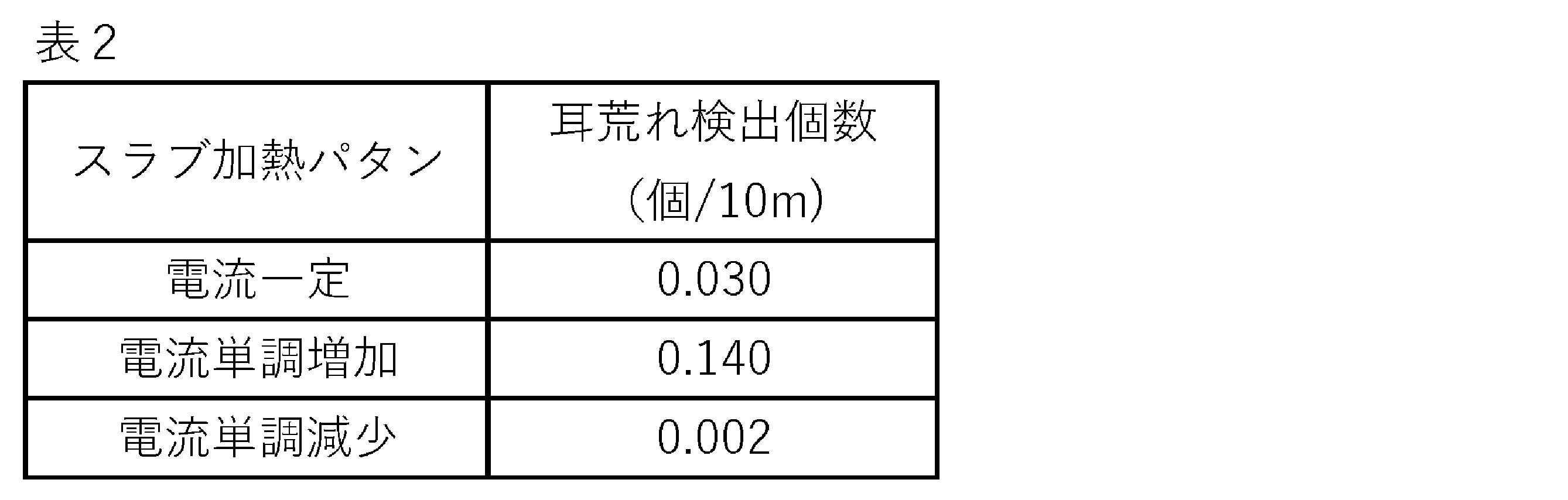
- Table 2 shows the result of investigating the number of detected number of rough edges on the coil. The results are shown as the value obtained by dividing the detected number by the coil length. As in the case after cold rolling, it was clarified that under the condition that the coil current was monotonously decreased, the number of rough edges detected decreased compared to the conventional constant current condition for comparison.
- the slab heating process by induction heating in hot rolling has a strong effect on the frequency of cracking at the coil edge. Furthermore, in addition to positively reviewing the slab heating conditions, the present invention was discovered as a result of diligent studies on improving the structure of steel by optimizing each manufacturing process.
- a hot-rolled sheet having a thickness of 2.7 mm was obtained by hot rolling so that The hot-rolled sheet thus obtained was subjected to hot-rolled sheet annealing at 1000° C. for 60 seconds to obtain a hot-rolled sheet annealed sheet.
- the hot-rolled annealed sheet is subjected to primary cold rolling to obtain an intermediate sheet thickness of 1.8 mm, further subjected to intermediate annealing at 1120° C. for 80 seconds, and then subjected to secondary cold rolling to obtain a final sheet.
- a cold-rolled sheet having a thickness of 0.22 mm was obtained.
- the cold-rolled sheet was subjected to primary recrystallization annealing by a known method to obtain a primary recrystallization annealing sheet, and then the primary recrystallization annealing sheet was subjected to secondary recrystallization annealing to obtain a steel sheet. Furthermore, for the purpose of flattening the steel sheet and applying an insulating tension coating, the coil after the secondary recrystallization annealing was annealed at 830° C. for 10 seconds to produce a coil of grain-oriented electrical steel sheet. Table 4 also shows the results of the investigation of the number of detected number of rough edges on the coil.
- the inventors thought that the number of edge cracks could be further reduced by increasing the ductility by changing the steel composition.
- the composition of the produced slab is as shown in Table 3 above.
- changing the carbon content of the material is known as an easy method for refining the steel structure and increasing the ductility.
- the carbon content of the material also has a large effect on the texture of the primary recrystallized plate, and there is a risk of impairing the magnetism after secondary recrystallization. Therefore, the inventors have investigated the refinement of the structure by finely adjusting the amounts of Al and N.
- Al and N form AlN, which is an inhibitor, but if they are precipitated in just the right amount, the amount of solid solution Al or solid solution N decreases and the Ostwald growth of AlN is retarded. Therefore, the precipitates do not coarsen in the annealing step, the coarsening of the crystal grain size is strongly suppressed, and the fine structure is maintained. Since the condition under which Al and N are precipitated in just the right amount is when the atomic ratio of Al and N is the same (1:1), the value of the Al/N mass ratio is approximately 2.0. As shown in Table 4, when compared at a slab heating temperature of 1320°C, steels A, D and E have rough edges (edges) formed over 3 cm in the width direction of the flattened annealed sheets. 0.020 or less per 10m length. That is, it is considered that rough edges can be well suppressed under the condition that the value of Al/N is 1.8 or more and 3.0 or less.
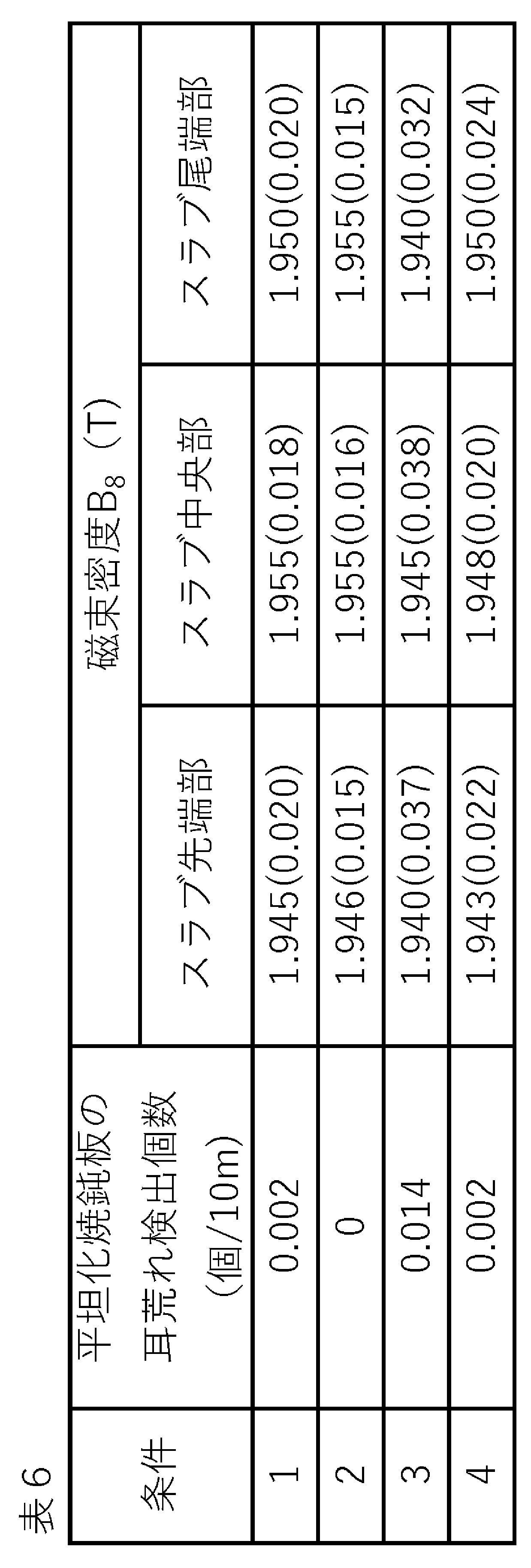
- Table 6 shows the evaluation results of edge roughness and magnetic flux density of grain-oriented electrical steel sheet coils manufactured using this slab.
- the magnetic flux density was measured by SST of 33 pieces in total, 11 pieces of test pieces of 300 mm in the rolling direction and 100 mm in the width direction cut out along the coil width direction by 3 rows in the rolling direction. Also, in Table 6, the average value of the measurement results was calculated, and the average value and the standard deviation are shown in parentheses.
- C 0.030 to 0.085 mass% If C is less than 0.030 mass%, the grain boundary strengthening effect of C is lost, cracks occur in the slab, and production is hindered. In addition, non-uniform deformation, which is preferable for improving magnetic properties and is caused by strain aging during rolling, is suppressed. On the other hand, when the amount of C exceeds 0.085 mass%, it becomes difficult to reduce the amount of C to 0.005 mass% or less at which magnetic aging does not occur in the primary recrystallization annealing. Therefore, C should be in the range of 0.030 to 0.085 mass%. The amount of C is preferably 0.040 mass% or more. Also, the amount of C is preferably 0.080 mass% or less.
- Si 2.00 to 4.50 mass%
- Si is an important element for increasing the resistivity of the steel sheet and reducing iron loss. Addition of less than 2.00 mass% of Si cannot sufficiently exhibit these effects. On the other hand, when the amount of Si exceeds 4.50 mass%, the brittleness of the steel sheet increases, making rolling difficult. Therefore, Si should be in the range of 2.00 to 4.50 mass%.
- the amount of Si is preferably 2.50 mass% or more, more preferably 3.00 mass% or more.
- the Si content is preferably 4.50 mass% or less, more preferably 4.00 mass% or less.
- Mn 0.03-0.50 mass%
- Mn is an element necessary for improving the hot workability of steel. A Mn content of less than 0.03 mass% is not sufficient to obtain the above effect. On the other hand, when the Mn amount exceeds 0.50 mass%, the magnetic flux density of the product sheet is lowered. Therefore, Mn should be in the range of 0.03 to 0.50 mass%.
- the amount of Mn is preferably 0.05 mass% or more, more preferably 0.07 mass% or more. Also, the Mn content is preferably 0.20 mass% or less, more preferably 0.15 mass% or less.
- Acid-soluble Al (Sol. Al): 0.005 mass% or more and less than 0.025 mass% Al plays a role as an inhibitor and is an important element for secondary recrystallization of Goss-oriented grains, and exhibits its effect. In order to do so, addition of 0.005 mass% or more is required. On the other hand, if it is added excessively, grain growth is excessively suppressed and secondary recrystallization of Goss-oriented grains is prevented.In addition, a dense oxide film is formed on the surface, making it difficult to control the amount of nitriding during nitriding. or inhibit decarburization. Therefore, sol. The amount of Al is suppressed to less than 0.025 mass%. sol.
- the Al content is preferably 0.007 mass% or more, more preferably 0.010 mass% or more. Also, sol.
- the Al content is preferably 0.022 mass% or less, more preferably 0.018 mass% or less.
- N 0.0030 to 0.0090 mass% N, like Al, plays a role as an inhibitor and is an important element for secondary recrystallization of Goss-oriented grains. On the other hand, since N may cause defects such as blistering during slab heating, it is suppressed to 0.0090 mass% or less. A more preferable range is defined by Al/N below.
- sol. Al/N is 1.7 or more and 3.0 or less N combines with Al to precipitate inhibitor AlN. At that time, Al and N are bonded at an atomic ratio of 1:1 and a mass ratio of approximately 2:1. In the present invention, the formation of fine ferrite crystal grains is important for increasing ductility, and for this purpose, AlN precipitates must be finely dispersed. Such precipitates coarsen through Ostwald growth during annealing, and the growth rate is thought to increase as the amount of dissolved Al and dissolved N increases. Therefore, Al and N form AlN at a mass ratio of 2:1, just enough. be done. Based on the experiments described above, sol. A suitable range for Al/N is from 1.7 to 3.0. Preferably, the lower limit of Al/N is 1.8. Also, preferably, the upper limit of Al/N is set to 2.5.
- S 0.0005 to 0.0300 mass% S combines with Mn to form an inhibitor, but if it is less than 0.0005 mass%, the absolute amount of the inhibitor is insufficient, resulting in insufficient suppression of normal grain growth.
- S content exceeds 0.0300 mass%, desulfurization becomes incomplete in the secondary recrystallization annealing, causing iron loss deterioration. Therefore, S should be in the range of 0.0005 to 0.0300 mass%. More preferably 0.0015 mass% or more, still more preferably 0.0030 mass% or more.
- At least one element selected from P, As and Sb 0.005 to 0.500 mass% each P and Sb form a solid solution in the base iron and act as inhibitors to enhance the selective growth of Goss-oriented grains. It is an element necessary to generate 0.005 mass% or more of each is added to obtain the effect. On the other hand, if they are excessively added, the rollability is impaired and production is hindered, so the upper limit of each is made 0.500 mass%. More preferably, they are 0.020 mass% or more and 0.150 mass% or less.
- As, which is a homologous element can be added in the above range because the effect of improving the magnetic properties is recognized.
- As is a toxic element
- As when As is used, it is used in combination with P and/or Sb, and more preferably, As is used in the range of 0.001 to 0.010 mass%.
- the remainder of the steel slab other than the above components is Fe and unavoidable impurities.
- the steel slab further contains Se: 0.0005 to 0.0200 mass%, Ni: 0.01 to 1.50 mass%, and Cr: 0.03 to 0.05 mass%. 50 mass%, Cu: 0.03 to 0.50 mass%, Sn: 0.005 to 0.500 mass%, Bi: 0.005 to 0.500 mass%, Mo: 0.005 to 0.100 mass%, B: 0 .0002 to 0.0025 mass%, Te: 0.0005 to 0.0100 mass%, Zr: 0.001 to 0.010 mass%, Nb: 0.001 to 0.010 mass%, V: 0.001 to 0.010 mass% % and Ta: one or more selected from 0.001 to 0.010 mass% may be contained as appropriate.
- ⁇ Production method Next, a method for manufacturing the grain-oriented electrical steel sheet of the present invention will be described.
- ⁇ Heating process> A steel material having the chemical composition described above is melted by a conventional refining process, and then a steel slab is formed by a conventional ingot-slabbing-rolling method or continuous casting method. Alternatively, a thin steel slab with a thickness of 100 mm or less may be produced by direct casting. These steel slabs are heated and held to an extraction temperature Tr of 1380° C. or less and subjected to hot rolling.
- a more preferable holding temperature is a temperature range in which the ⁇ phase does not precipitate.
- the heating temperature of the slab is preferably 1350° C. or less.
- the lower limit of Tr is not particularly limited as long as it is higher than the ⁇ phase precipitation temperature, but about 1200°C is preferable.
- the slab temperature is based on the surface temperature of the steel slab.
- the slab heating in actual operation it is difficult to maintain the slab temperature exactly at the target soaking temperature.
- Tr (°C) it is necessary to heat the slab at a temperature T that satisfies the relationship Tr-10°C ⁇ T ⁇ Tr+10°C for 5 minutes or longer. That is, the relational expression relating to the temperature T means that ⁇ 10° C. is provided as the allowable range of temperature variation.
- the heating time at this temperature T is less than 5 minutes, the temperature unevenness in the slab formed during the temperature rise due to induction heating is not sufficiently smoothed, and the temperature drops depending on the position of the slab. There is a possibility that the inhibitor is not sufficiently solid-dissolved, resulting in deterioration of magnetism. More preferably, the time is 10 minutes or longer.
- the upper limit of the heating time is not particularly limited, but it is preferably 60 minutes or less because an excessively long heating time impedes productivity.
- the slab heating of the present invention is carried out by the method of induction heating.
- the power supply frequency for such induction heating is set to 20 Hz or more and 1000 Hz or less.
- induction heating due to the skin effect, heat generation on the surface layer side of the slab becomes stronger, and this becomes more pronounced as the frequency is higher.
- a temperature difference occurs between the inside of the slab and the surface layer slab temperature measured by a radiation thermometer that controls the slab temperature. Therefore, in order to uniformly heat the slab, the lower the frequency, the lower the frequency, which is 1000 Hz or less.
- it is 300 Hz or less. More preferably, it is 200 Hz or less.
- the frequency is set to 20 Hz or higher for efficient induction heating.
- it is 50 Hz or higher.
- gas atmosphere heating can be added to a part of the slab heating as long as the induction heating conditions satisfy the present invention.
- the current flowing through the coil during induction heating is controlled so that its average value monotonically decreases.
- the monotonically decreasing means that the fluctuation due to the variation does not increase by more than ⁇ 5% with respect to the current value at the start of heating, and the current value immediately before the end of heating is 5% with respect to the current value at the start of heating. means to decrease by more than %.
- the current value may not change until the middle stage of heating, but it is preferable that the current value immediately before the end of heating is lower than that at the start of heating by at least about 10%.
- the measured value of the coil current is not constant due to variations in measurement and alternating current, the above average value is the average value for 5 minutes.
- the induction heating frequency in the heating step of the steel slab, it is preferable to monotonically increase the induction heating frequency.
- monotonically increase the frequency means to gradually increase the frequency so that the frequency at the end of heating is higher than the frequency at the start of heating, and it is preferable not to decrease the frequency during heating.
- the mechanism by which the characteristics are improved by gradually increasing the frequency is largely unknown, but for example, the following reasons are considered. That is, the energy emitted from a blackbody is proportional to the fourth power of the temperature, which is approximately true even when the slab is heated, and the higher the temperature, the more energy tends to be lost from the slab surface. Therefore, since the slab temperature rises in the second half of slab heating, heat extraction from the slab surface tends to increase.
- induction heating with a higher frequency in the latter half of the heating, it is possible to preferentially generate heat on the slab surface where heat removal is large, and as a result, it is possible to achieve a more uniform temperature distribution over the entire slab. it is conceivable that.
- the slab heated by such a procedure is subjected to rough rolling and finish rolling, and coiled as a hot-rolled sheet.
- the thickness of the hot-rolled sheet is preferably in the range of 1.5 mm or more and 4.0 mm or less.
- the rolling end temperature is set to 950° C. or less at at least one of the leading end and the trailing end.
- the structure recrystallized during rolling becomes coarse, which causes a decrease in ductility of the steel in the subsequent steps, impairing manufacturability. More preferably, it is 920° C. or less.
- the lower limit of the rolling end temperature is not particularly limited as long as the slab can be coiled as a hot-rolled sheet, but it is about 850°C.
- the hot-rolled sheet in order to suppress coarsening of the inhibitor, is cooled for 1 second or more at a cooling rate of 100 ° C./second or more within 2 seconds after the end of finish rolling, and the heat after cooling is applied. It is preferable to wind the rolled sheet at a coiling temperature of 600° C. or less to complete the hot rolling process. More preferably, the hot-rolled sheet is cooled within 1 second after finishing rolling. Subsequently, skin-pass rolling may be performed after finish rolling and before hot-rolled sheet annealing. Skin pass rolling can correct the shape of the steel sheet.
- hot-rolled sheet annealing is applied to the hot-rolled sheet after the finish rolling or the hot-rolled sheet obtained by the skin-pass rolling.
- the soaking temperature for hot-rolled sheet annealing is 750° C. or higher and 1170° C. or lower.
- the soaking time is 5 seconds or more and 90 seconds or less. If the soaking temperature is less than 750°C, the amount of diffusion of the inhibitor-forming element such as Al is insufficient, and the inhibitor is not sufficiently precipitated. This is because the remaining strain cannot be removed, making it difficult to obtain a primary recrystallized structure with regular grains, and inhibiting the growth of secondary recrystallized grains.
- the soaking temperature exceeds 1170° C.
- the inhibitor becomes a solution and the amount of the inhibitor that cannot precipitate increases.
- the soaking time is less than 5 seconds, the inhibitor-forming element cannot sufficiently diffuse and the inhibitor is not sufficiently precipitated, and it is difficult to obtain a primary recrystallized structure with regular grains.
- the soaking time exceeds 90 seconds, the inhibitor is coarsely precipitated and the grain growth suppressing effect of the inhibitor cannot be sufficiently exhibited, and the primary recrystallized structure becomes excessively coarse, impairing productivity.
- the soaking temperature for hot-rolled sheet annealing is preferably 850° C. or higher.
- the soaking temperature for hot-rolled sheet annealing is preferably 1150° C. or less.
- the hot-rolled sheet annealing step additionally include a step of holding at a temperature of 700° C. or higher and 900° C. or lower for 5 seconds or more and 180 seconds or less.
- a temperature of 700° C. or higher and 900° C. or lower for 5 seconds or more and 180 seconds or less.
- AlN which is not sufficiently precipitated in the hot-rolling process, is precipitated, but it is known that AlN is efficiently precipitated in the above temperature range.
- the aim is to maintain high ductility by actively precipitating inhibitors and inhibiting grain growth. Therefore, performing the additional annealing described above can further precipitate AlN. Therefore, it is preferable.
- the temperature does not necessarily have to be maintained within the above range, and may be maintained in the temperature range of 700° C.
- the temperature is 750° C. or higher.
- the time required is more preferably 10 seconds or more, and more preferably 180 seconds or less.
- the hot-rolled annealed sheet is cold-rolled once or cold-rolled twice or more with intermediate annealing to obtain a cold-rolled sheet having a final thickness.
- the soaking temperature for the intermediate annealing is preferably in the range of 900 to 1200°C. If the soaking temperature is 900° C. or higher, it effectively prevents the recrystallized grains after the intermediate annealing from becoming too fine, and further effectively prevents the decrease of the Goss nuclei in the primary recrystallized structure, and the directional electromagnetic The magnetic properties of the steel sheet are further improved. On the other hand, if the soaking temperature is 1200° C. or less, the crystal grains are not excessively coarsened, and a more preferable primary recrystallized structure with uniform grains can be obtained. More preferably, it is 1150° C. or less.
- the cold rolling may be either tandem rolling (unidirectional rolling) or reverse rolling, and a known warm rolling technique or interpass aging technique may be used.
- the cutting width is preferably 5 mm or more.
- the upper limit of the cutting width is not particularly limited, it is about 30 mm or less from the viewpoint of productivity and the like.
- Such cutting and removal may be performed continuously before the first cold rolling, that is, after the hot-rolled steel sheet is annealed in the cold-rolling process or the preceding process line, or may be performed exclusively for processing. It may be transferred to the line and performed as an additional step.
- known techniques such as a mechanical trimmer, laser cutting, water jet cutting, and the like can be applied.
- the final thickness of the cold-rolled sheet is preferably 0.15 mm or more from the viewpoint of reducing the rolling load.
- the upper limit of the final plate thickness is 0.35 mm.
- ⁇ Primary recrystallization annealing> The cold-rolled sheet having the final thickness is then subjected to primary recrystallization annealing.
- the annealing temperature in this primary recrystallization annealing is preferably in the range of 800 to 900 ° C. from the viewpoint of speeding up the decarburization reaction when decarburization annealing is also used, and the atmosphere is a humid atmosphere. is preferred.
- decarburization annealing may be performed separately from the primary recrystallization annealing.
- the amount of C is reduced to the level of an impurity, and the adverse effects of C due to magnetic aging can be eliminated.
- ⁇ Secondary recrystallization annealing> After the primary recrystallization annealing, the primary recrystallization annealing sheet is then subjected to secondary recrystallization annealing to obtain a grain-oriented electrical steel sheet.
- an annealing separator mainly composed of MgO is applied to the surface (one side or both sides) of the primary recrystallization annealed sheet, and after drying, the secondary It is preferable to apply recrystallization annealing.
- "mainly composed of MgO” refers to containing 80% by mass of MgO with respect to the entire annealing separator.
- the annealing separating agent is not applied, or secondary recrystallization annealing is performed using an annealing separating agent mainly composed of silica, alumina, or the like. preferably applied.
- "mainly composed of silica, alumina, or the like” means that 80% by mass of silica, alumina, or the like is contained with respect to the entire annealing separator.
- the forsterite coating is not formed, it is also effective to apply the annealing separator by electrostatic application that does not bring in moisture.
- a known heat-resistant inorganic material sheet may be used instead of the annealing separator. Heat-resistant inorganic material sheets include, for example, silica, alumina, and mica.
- the temperature is maintained at around 800 to 1050 ° C. for 20 hours or more to express and complete the secondary recrystallization, and then the temperature is further increased to 1100 ° C. or higher. It is preferable to raise the temperature to It is preferable to further raise the temperature to about 1200° C. when the iron loss property is emphasized and the purification treatment is performed.
- the annealing can be completed by raising the temperature up to 800 to 1050° C. because the secondary recrystallization should be completed.
- N, Al, S, and Se are diffused and released into the annealing separator and the annealing atmosphere during the secondary recrystallization annealing. Both have decreased in comparison. Therefore, after the secondary recrystallization annealing, N, Al, S, and Se are treated as inevitable impurities in addition to the inevitable impurities in the slab.
- the secondary recrystallization annealed sheet (grain-oriented electrical steel sheet) may be washed with water, brushed, or pickled to remove the unreacted annealing separating agent adhering to the surface of the steel sheet. Further, the secondary recrystallization annealed sheet may be further subjected to flattening annealing. Since the secondary recrystallization annealing is usually performed in a coil state, the coil tends to curl. This curl may degrade iron loss characteristics. Iron loss can be further reduced by correcting the shape by applying flattening annealing.
- a tension imparting coating that imparts tension to the steel sheet as the insulating coating.
- a method of coating the tension-imparting coating via a binder, or a method of vapor-depositing an inorganic material on the surface layer of the steel sheet by physical vapor deposition or chemical vapor deposition can be employed. According to these methods, it is possible to form an insulating coating which is excellent in coating adhesion and has a remarkably large effect of reducing iron loss.
- the grain-oriented electrical steel sheet In order to further reduce iron loss, it is preferable to subject the grain-oriented electrical steel sheet to magnetic domain refining treatment.
- a method of magnetic domain refining treatment there is a method of forming grooves on the surface (front or back) of a grain-oriented electrical steel sheet (final product sheet), and a linear or point-like thermal strain by electron beam irradiation, laser irradiation, plasma irradiation, etc.
- a known magnetic domain refining treatment method such as a method of introducing impact strain, a method of etching the surface of a cold-rolled sheet that has been cold-rolled to the final thickness or a steel sheet surface in an intermediate process to form grooves, can be used. .
- manufacturing conditions other than the above conditions can be based on a conventional method.
- the method shown in the present invention even in a composition system that actively uses Group 15 elements such as P and Sb, it is possible to prevent the formation of rough edges on the edges in the coil width direction of cold-rolled sheets and flattened annealed sheets. can be suppressed. As a result, as compared with the prior art, strip cracks originating from rough edges are reduced during strip threading, and good productivity can be obtained. Specifically, the number of rough edges (edge cracks) formed exceeding 3 cm in the sheet width direction can be 0.020 or less per 10 m of the flattened annealed sheet (steel sheet).
- a grain-oriented electrical steel sheet having a magnetic flux density B8 of 1.94 T or more and a thickness of 0.35 mm or less can be manufactured.
- the magnetic flux density B8 was measured according to the Epstein method described in JIS C2550 by cutting out an Epstein test piece from the grain-oriented electrical steel sheet.
- the grain-oriented electrical steel sheet obtained by the present invention exhibits a high magnetic flux density, and if the grain-oriented electrical steel sheet produced by the present technology is used in a transformer, not only can the energy use efficiency be reduced, but also the transformer Instrument noise can also be reduced.
- the method of manufacturing grain-oriented electrical steel sheets it is possible not only to use electric power equipment such as transformers with high efficiency, but also to contribute to the reduction of noise during operation caused by magnetostriction. can.
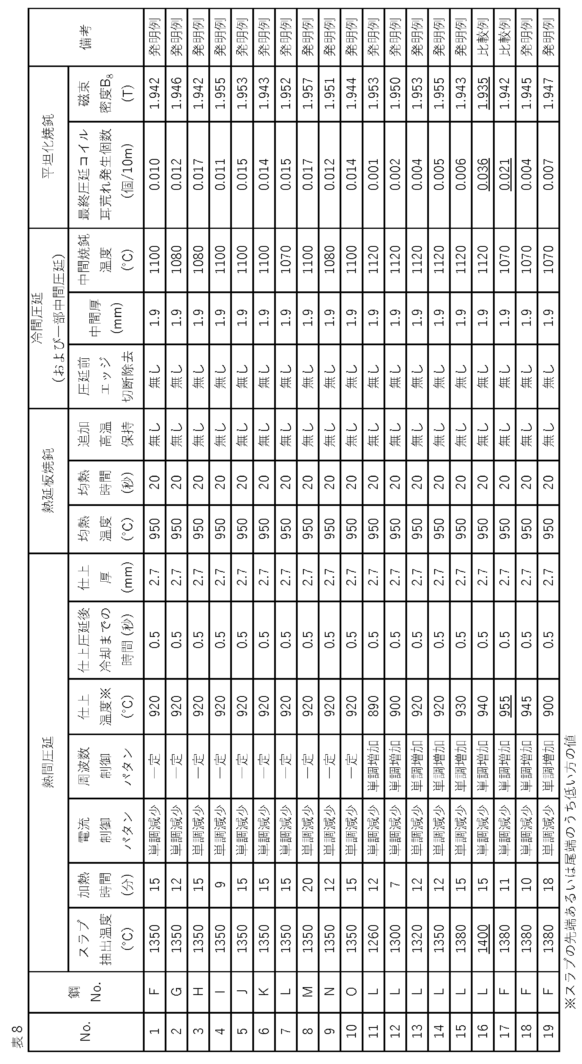
- the steel slab is slab-heated under the conditions shown in Table 8, the steel slab is subjected to rough rolling to obtain a rough rolled sheet, the rough rolled sheet is subjected to finish rolling to obtain a hot rolled sheet, and the hot rolled sheet is cooled. , the hot-rolled sheet after cooling was wound up.
- the cooling was carried out at a cooling rate of 100°C/second or more for 1 to 5 seconds within 2 seconds after finishing rolling, and the coiling was carried out at a temperature range of 450 to 600°C.
- the hot-rolled sheet was subjected to hot-rolled sheet annealing to obtain a hot-rolled sheet annealed sheet.
- Induction heating was used for slab heating, and the frequency was constant or increased monotonously in the range of 50 Hz to 300 Hz.
- the width of the cut when the coil ends were cut and removed was 5 mm.
- a product sheet was obtained by applying a phosphate-based insulation tension coating, baking, and flattening annealing for the purpose of flattening the steel strip.
- An Epstein test piece was cut out from the obtained product sheet, and the magnetic flux density B8 was measured by the method described above.
Landscapes
- Chemical & Material Sciences (AREA)
- Engineering & Computer Science (AREA)
- Materials Engineering (AREA)
- Mechanical Engineering (AREA)
- Metallurgy (AREA)
- Organic Chemistry (AREA)
- Physics & Mathematics (AREA)
- Thermal Sciences (AREA)
- Crystallography & Structural Chemistry (AREA)
- Electromagnetism (AREA)
- Manufacturing & Machinery (AREA)
- Dispersion Chemistry (AREA)
- Power Engineering (AREA)
- Manufacturing Of Steel Electrode Plates (AREA)
Abstract
Description
ここで、方向性電磁鋼板の低鉄損化の方法としては、鋼板自身の比抵抗の増大、被膜の張力の増大、鋼板の薄手化などの手法のほかに、鋼板の表面加工による方法、および結晶粒の{110}<001>方位(以降、Goss方位という)への結晶方位の先鋭化による方法が挙げられる。
なお、磁気特性の指標としては、励磁周波数:50Hzの交流磁場で1.7Tまで磁化したときの鋼板1kgあたりの鉄損W17/50と、特に、Goss方位への結晶方位の先鋭化の指標である磁場の強さ:800A/mにおける磁束密度B8が主に用いられている。
例えば、特許文献3に開示の方法では、鋼中にAlを添加し、熱間圧延後に750~1200℃での熱延板焼鈍を施し、その後に急冷することによって微細なAlNを析出させ、極めて高い磁束密度を得ている。
例えば、特許文献4には、方向性電磁鋼板用スラブの在炉時間短縮と材質ばらつき低減のために、1150℃から1250℃までの温度域の高温化に誘導加熱が利用できることが示されている。
特許文献5には、均熱温度に応じて均熱時間を調整することによって、Bi元素の脱離をミニマム化する技術が示されている。
特許文献6には、スラブを1400℃から1470℃まで高温加熱するに際し、誘導加熱の周波数を30Hzから300Hzにすることによって、スラブ表面からの抜熱を強化し、表面粒界酸化等の表面欠陥生成を抑制できることが示されている。
まず、インヒビタ構成元素であるMnやS、Al、Nの低減を、例えば、特許文献6に示される従来成分量を比較に検討したが、インヒビタの析出量が減少したために、抑制力は低減し、二次再結晶後の磁性も劣位なものしか得られなかった。そこで、析出物を形成せず、固溶状態で抑制力増大に効果がある元素を探索し、PやSbなど粒界偏析元素を含む第15族元素の活用を思いついた。例えば、Sbの添加効果については、特公平2-115319号公報に開示されている。
その結果、スラブの組成を後述の範囲とすることによって、スラブの加熱温度を従来以上に低減しても、インヒビタが溶体化し、後の工程において高いインヒビタ抑制力を発揮できることを見出した。
しかしながら、かかる耳荒れの抑止技術は、仕上焼鈍条件を最適化するものであり、PやSbといった第15族元素を積極的に活用したものではなかった。
なお、耳荒れの発生メカニズムについては、諸説あるが、特開2002-105537号公報に一つの推定が示されている。それは、「耳割れは、熱間圧延中に板端部に長手方向(圧延方向)の引張張力が作用することによって発生するが、その際、析出物や結晶粒界等が割れの起点になっていると考えられる。ところで、スラブを融点に近い高温まで加熱する時、昇温速度が速いと介在物、析出物が母相へ十分に固溶しない状態で高温となる。その結果として、介在物、析出物が存在する部分およびその周辺は局所的に母相と組成が異なり、従って融点も異なることになる。この時、融点が低くなると、局所的に液化を生じることになる。このように、高温への昇温が速いと、局所的に液化を生じてしまい、そこが耳割れの起点となって耳割れが発生し易くなる。」というものである。
1.C:0.030~0.085mass%、Si:2.00~4.50mass%、Mn:0.03~0.50mass%、S:0.0005~0.0300mass%、sol.Al:0.005mass%以上0.025mass%未満、N:0.0030~0.0090mass%、および、P、AsおよびSbから選ばれる少なくとも1つの元素を0.005~0.500mass%の範囲で含有し、sol.Al/Nが1.7以上3.0以下を満たし、残部がFeおよび不可避的不純物からなる鋼スラブを、
誘導加熱により1380℃以下のスラブ抽出温度Tr(℃)まで加熱し、Tr-10℃≦T≦Tr+10℃の範囲を満足する温度Tで5分間以上にわたり保持する加熱工程において、加熱の時間の経過とともにスラブに流れる平均電流値を単調に減少させ、かつ、誘導加熱の周波数を20Hz以上1000Hz以下の範囲にて行い、
前記スラブに仕上げ圧延を施して熱延板とする熱間圧延において、該熱延板の先端あるいは尾端の少なくともいずれか一方における圧延終了温度を950℃以下とし、かかる熱延板に750℃以上1170℃以下の温度にて5秒以上90秒以下の時間均熱する熱延板焼鈍を施して熱延板焼鈍板としたのち、
前記熱延板焼鈍板に、1回または中間焼鈍を挟む2回以上の冷間圧延を施して最終板厚の冷延板とし、該冷延板に一次再結晶焼鈍ついで二次再結晶焼鈍を施す、方向性電磁鋼板の製造方法。
Se:0.0005~0.0200mass%、
Ni:0.01~1.50mass%、
Cr:0.03~0.50mass%、
Cu:0.03~0.50mass%、
Sn:0.005~0.500mass%、
Bi:0.005~0.500mass%、
Mo:0.005~0.100mass%、
B:0.0002~0.0025mass%、
Te:0.0005~0.0100mass%、
Zr:0.001~0.010mass%、
Nb:0.001~0.010mass%、
V:0.001~0.010mass%および
Ta:0.001~0.010mass%
からなる群より選ばれる1種または2種以上を含有する、前記1に記載の方向性電磁鋼板の製造方法。
Ni:0.01~1.50mass%、
Cr:0.03~0.50mass%、
Cu:0.03~0.50mass%、
Sn:0.005~0.500mass%、
Bi:0.005~0.500mass%、
Mo:0.005~0.100mass%、
B:0.0002~0.0025mass%、
Te:0.0005~0.0100mass%、
Zr:0.001~0.010mass%、
Nb:0.001~0.010mass%、
V:0.001~0.010mass%および
Ta:0.001~0.010mass%
からなる群から選ばれる1種または2種以上を含有する、前記8に記載の方向性電磁鋼板。
はじめに、方向性電磁鋼板用スラブを誘導加熱炉で加熱する際の加熱パタンの変更の耳荒れ抑制に対する有効性を検証するため、以下の実験を行った。
<実験1>
残部がFeおよび不可避的不純物からなる鋼素材(C:0.050mass%、Si:3.40mass%、Mn:0.05mass%、sol.Al:0.014mass%、N:0.007mass%、S:0.020mass%、Sb:0.10mass%)を溶製し、鋼スラブとした後、かかる鋼スラブを、抽出温度:1320℃を目標とし誘導加熱炉によって加熱した。図1に、加熱中、コイルに流れる電流値を示す。
表1に示したとおり、スラブ加熱時において、コイル電流を単調増加させた条件は、コイル電流を一定とする条件に対して、耳荒れ検出個数が増大した。一方で、コイル電流を単調減少させた条件では、コイル電流を一定とする条件に対して、耳荒れ検出個数が低減することが明らかとなった。

冷延後と同様、コイル電流を単調減少させた条件では、比較とする従来の電流一定条件に対し、耳荒れ検出個数が低減することが明らかとなった。
《実験2》
表3および残部がFeおよび不可避的不純物である成分組成からなる鋼素材を溶製し、鋼スラブとした後、コイル電流を単調減少させる条件にて、誘導加熱を用い、スラブを表4中に示した各温度Trまで加熱し、Tr-10℃~Tr+10℃の温度範囲で10分間保持し、温度Trでスラブを抽出した後、熱延板の先端および尾端の平均の仕上げ温度が930℃となるように熱間圧延を行い板厚2.7mmの熱延板を得た。かくして得られた熱延板を、1000℃、60秒の条件で熱延板焼鈍を施して熱延板焼鈍板とした。次いで、かかる熱延板焼鈍板に一次冷間圧延を施して中間板厚1.8mmとし、さらに1120℃、80秒の条件の中間焼鈍を施した後、二次冷間圧延を施して最終板厚0.22mmの冷延板とした。
その後は、公知の方法によって、前記冷延板に一次再結晶焼鈍を施して一次再結晶焼鈍板とした後、一次再結晶焼鈍板に二次再結晶焼鈍を施して鋼板とした。さらに、かかる鋼板の平坦化と絶縁張力被膜塗布を目的として、二次再結晶焼鈍後のコイルを830℃、10秒の条件で焼鈍し、方向性電磁鋼板のコイルを作製した。該コイルについて、耳荒れ検出個数を調査した結果を表4に併記する。


一般的に、鋼の延性は結晶粒径が小さいほど高くなることから、熱延板および熱延板焼鈍板粒径の大きい高温スラブ加熱材は脆性が高く、圧延中に端部から亀裂が生成したものと考えられる。
そこで、発明者らは、Al、N量の微調整による組織微細化を検討した。AlとNは、インヒビタであるAlNを形成するが、これらが過不足なく析出されれば、固溶Alあるいは固溶N量が減少し、AlNのオストワルド成長が遅延される。そのため、焼鈍工程において析出物が粗大化せず、結晶粒径の粗大化が強く抑制され、微細な組織が保持される。AlとNが過不足なく析出する条件は、AlとNの原子数比が同じ場合(1:1)であるため、Al/Nの質量比の値ではおよそ2.0の条件となる。
表4に示されるように、スラブ加熱温度:1320℃で比較した場合、平坦化焼鈍板の耳荒れに関し、鋼A、DおよびEは、板幅方向に3cmを超えて形成した耳荒れ(耳割れ)が10m長さ当たりの割れ個数で0.020個以下を満足した。すなわち、Al/Nの値が1.8以上3.0以下の条件で耳荒れを良く抑制できると考えられる。
表5に、スラブ加熱条件を示す。周波数を変えた条件であってもヒートパタンが揃うように、コイル電流値を調整しながら、いずれの条件でも、狙いの抽出温度(=1325℃)±10℃の範囲内で約15分間の加熱を行った。なお、加熱開始後20、30、40、50分の時点ではいずれも加熱条件を変更したので、変更前後の条件を併記している。
また、表6に、本スラブを用いて製造した方向性電磁鋼板コイルの耳荒れと磁束密度の評価結果を示す。

先ず、本発明の方向性電磁鋼板の素材に用いる鋼スラブの成分組成の適正範囲およびその限定理由について説明する。なお、以下の説明において、「~」を用いて表される数値範囲は、「~」の前後に記載される数値を下限値及び上限値として含む範囲を意味する。
Cは、0.030mass%に満たないと、Cによる粒界強化効果が失われ、スラブに割れを生じ、製造に支障をきたす。また、圧延加工中のひずみ時効によって生じる磁気特性向上に好ましい不均一変形を抑制する。一方、C量が0.085mass%を超えると、一次再結晶焼鈍で、C量を磁気時効の起こらない0.005mass%以下に低減することが困難となる。よって、Cは0.030~0.085mass%の範囲とする。C量は、好ましくは0.040mass%以上とする。また、C量は、好ましくは0.080mass%以下とする。
Siは、鋼板の比抵抗を高め、鉄損を低減するために重要な元素である。2.00mass%未満のSi添加では、これらの効果が十分に発揮できない。一方、Si量が4.50mass%を超えると、鋼板の脆性が増し、圧延加工が困難となる。よって、Siは2.00~4.50mass%の範囲とする。Si量は、好ましくは2.50mass%以上、より好ましくは3.00mass%以上とする。また、Si量は、好ましくは4.50mass%以下、より好ましくは4.00mass%以下とする。
Mnは、鋼の熱間加工性を改善するために必要な元素である。上記効果を得るためには、Mn量が0.03mass%未満では十分ではない。一方、Mn量が0.50mass%を超えると、製品板の磁束密度が低下するようになる。よって、Mnは0.03~0.50mass%の範囲とする。Mn量は、好ましくは0.05mass%以上、より好ましくは0.07mass%以上とする。また、Mn量は、好ましくは0.20mass%以下、より好ましくは0.15mass%以下とする。
Alは、インヒビタとしての役割を担い、Goss方位粒を二次再結晶させるのに重要な元素であり、その効力を発揮するためには0.005mass%以上の添加が必要である。一方、過度に添加されると、粒成長が過度に抑止されGoss方位粒が二次再結晶しなくなるばかりか、表面に緻密な酸化膜を形成し、窒化の際にその窒化量の制御を困難にしたり、脱炭を阻害したりすることがある。そのため、sol.Al量で0.025mass%未満に抑制する。sol.Al量は、好ましくは0.007mass%以上、より好ましくは0.010mass%以上とする。また、sol.Al量は、好ましくは0.022mass%以下、より好ましくは0.018mass%以下とする。
Nは、Alと同様、インヒビタとしての役割を担い、Goss方位粒を二次再結晶させるのに重要な元素であり、その効力を得るために0.0030mass%以上の添加が必要である。一方で、Nは、スラブ加熱時にフクレなどの欠陥の原因となることもあるため、0.0090mass%以下に抑制する。より好適な範囲については、以下のAl/Nにより規定される。
Nは、Alと結合してインヒビタAlNを析出する。その際のAlおよびNは、原子数比で1:1、質量比では、およそ2:1で結合している。本発明は、延性増大のため微細なフェライト結晶粒の形成が重要であり、そのために、AlNの析出物は微細に分散させる必要がある。かかる析出物は、焼鈍中、オストワルド成長を通じて粗大化するが、その成長速度は、固溶Al、固溶Nの量が多いほど高まると考えられる。従って、AlとNは、質量比2:1で過不足なくAlNを形成し、固溶Al、固溶Nの量が少ないほど、微細な析出物が保持され、ひいては微細なフェライト結晶粒が得られる。前述の実験に基づき、sol.Al/Nの適正範囲は、1.7から3.0である。好ましくは、Al/Nの下限を1.8とする。また、好ましくは、Al/Nの上限を2.5とする。
Sは、Mnと結合してインヒビタを形成するが、0.0005mass%未満では、インヒビタの絶対量が不足し、正常粒成長の抑制力不足となる。一方で、Sの含有量が0.0300mass%を超えると、二次再結晶焼鈍において、脱Sが不完全となるため、鉄損劣化を引き起こす。そのため、Sは、0.0005~0.0300mass%の範囲とする。より好ましくは0.0015mass%以上、さらに好ましくは0.0030mass%以上とする。
P、Sbは、地鉄中に固溶し、インヒビタとしてGoss方位粒の選択成長性を高めるほか、二次再結晶前組織の集合組織を改善し、Goss方位粒の二次再結晶を良好に生じさせるのに必要な元素である。その効果を得るためにそれぞれ0.005mass%以上添加する。一方で、過度に添加した場合、圧延性を損ない、製造に支障をきたすことから、上限はそれぞれ0.500mass%とする。より好ましくは、それぞれ0.020mass%以上または0.150mass%以下とする。
なお、同族元素であるAsは、磁性改善の効果が認められるので、上記範囲で添加することができる。有毒元素であるため、Asを活用する場合、Pおよび/またはSbと併用しつつ、より好ましくは、As:0.001~0.010mass%の範囲で使用する。
また、P、As、Sbは単独で含有するよりも、上記範囲で、P、AsおよびSbから選ばれる2つ以上の元素を含む方が好ましい。
次に、本発明の方向性電磁鋼板の製造方法について説明する。
<加熱工程>
前述した成分組成を有する鋼素材を、常法の精錬プロセスで溶製した後、常法の造塊-分塊圧延法または連続鋳造法で鋼スラブとする。あるいは、直接鋳造法で100mm以下の厚さの薄い鋼スラブを製造してもよい。これらの鋼スラブを、1380℃以下の抽出温度Trまで加熱保持し、熱間圧延に供する。また、かかる保持温度がγ相析出温度以下の場合、結晶相が二相化し、固溶元素がγ相やα相に濃化し、次工程以降の工程まで不均一な鋼組織が残り、磁性不良の要因となることから、より好ましい保持温度はγ相が析出しない温度域とする。さらに、1380℃超でスラブ加熱すると、熱間圧延前のフェライト粒径が過度に大きくなって、粗大な未再結晶組織が熱延板に形成され、鋼の延性を損なって圧延中に耳荒れを生じやすくする。スラブの加熱温度は、好ましくは1350℃以下である。一方、Trの下限はγ相析出温度よりも高ければ特に限定されないが1200℃程度が好ましい。なお、スラブ温度は、鋼スラブの表面温度を基準とする。
すなわち、上記温度Tにかかる関係式は、温度バラツキの許容範囲として±10℃を設けたことを意味する。
また、この温度Tでの加熱時間が5分を下回ると、誘導加熱に起因して昇温中に形成されたスラブ内の温度むらが十分にならされず、スラブ位置によっては温度が低くなってインヒビタが十分固溶されずに磁性劣化を招く可能性がある。より好ましくは、10分以上とする。加熱時間の上限は、特に制限されないが、過度な長時間化は生産性を阻害するため好ましくは60分以下とする。
なお、上記スラブ加熱は、誘導加熱の条件が本発明を満足していれば、その一部にガス雰囲気加熱をさらに追加することもできる。
なお、周波数を徐々に増大させることによって特性が改善したメカニズムについては不明なところが多いが、例えば以下のような理由を考えている。
すなわち、黒体より放出されるエネルギは、温度の4乗に比例するが、これは、スラブの加熱時にもおよそ成り立ち、温度が高いほど、スラブ表面からエネルギが失われる傾向にある。従って、スラブ加熱の後半は、スラブ温度が高温化するため、スラブ表面からの抜熱も大きくなる傾向がある。そこで、加熱後半により高い周波数による誘導加熱を適用することで、抜熱の大きいスラブ表面において優先的に発熱することが可能となる結果、スラブ全体でのより均一な温度分布を実現することができると考えられる。
かような手順で加熱したスラブを、粗圧延および仕上圧延によって、熱延板としてコイル状に巻取る。熱延板の板厚は、1.5mm以上4.0mm以下の範囲が好ましい。ここで、先端あるいは尾端の少なくともいずれか一方において、圧延終了温度を950℃以下とする。圧延終了温度が高い場合、圧延時に再結晶した組織が粗大化し、続く工程において鋼の延性低下を招いて製造性を損なう。より好ましくは、920℃以下である。なお、圧延終了温度の下限は、スラブが熱延板としてコイル状に巻取れれば特に限定されないが、850℃程度である。
続いて、仕上げ圧延終了後、熱延板焼鈍の前までに、スキンパス圧延を行ってもよい。スキンパス圧延により、鋼板の形状を矯正することができる。
次いで、仕上げ圧延後の熱延板、または上記のスキンパス圧延をして得た熱延板に、熱延板焼鈍を施す。熱延板焼鈍の均熱温度は、750℃以上1170℃以下とする。均熱時間は5秒以上90秒以下とする。均熱温度が750℃未満では、Alなどインヒビタ形成元素の拡散量が不足し、インヒビタが十分に析出しないほか、均熱温度が低い場合には、熱延板の圧延方向に伸びた結晶粒に残るひずみを除去できずに、整粒した一次再結晶組織を得ることが難しくなって二次再結晶粒の成長が阻害されるためである。一方、均熱温度が1170℃を超えて高温になると、インヒビタが溶体化し、析出できないインヒビタの量が増大する。
また、均熱時間が5秒に満たないと、インヒビタ形成元素が十分拡散できずにインヒビタが十分に析出しない、また、整粒した一次再結晶組織が得られにくい。一方、均熱時間が90秒を超えると、インヒビタが粗大に析出してインヒビタとしての粒成長抑制効果を十分発揮できない、また、一次再結晶組織が過度に粗大化して製造性を損なう。
熱延板焼鈍の均熱温度は、850℃以上が好ましい。一方、熱延板焼鈍の均熱温度は、1150℃以下が好ましい。
熱延板焼鈍後、かかる熱延板焼鈍板に、1回の冷間圧延、または、中間焼鈍を挟む2回以上の冷間圧延を施して最終板厚を有する冷延板とする。上記中間焼鈍の均熱温度は、900~1200℃の範囲とすることが好ましい。均熱温度が900℃以上であれば、中間焼鈍後の再結晶粒が細かくなりすぎることを効果的に防ぎ、さらに、一次再結晶組織におけるGoss核の減少を効果的に防いで、方向性電磁鋼板の磁気特性がより向上する。一方、均熱温度が1200℃以下であれば、結晶粒が粗大化しすぎず、整粒したより好ましい一次再結晶組織を得ることができるからである。より好ましくは、1150℃以下である。
なお、かかる切断除去は、1回目の冷間圧延の前、すなわち冷延工程や前工程ライン内の熱延板焼鈍板となった後で連続的に行っても良いし、加工のために専用ラインに移して追加工程として行ってもよい。切断方法は、機械式のトリマー機の他、レーザ切断、ウォータージェット切断など、公知に知られる技術が適用可能である。
最終板厚とした冷延板には、その後、一次再結晶焼鈍を施す。この一次再結晶焼鈍における焼鈍温度は、脱炭焼鈍を兼ねる場合には、脱炭反応を速やかに進行させる観点から、800~900℃の範囲とすることが好ましく、また、雰囲気は湿潤雰囲気とするのが好ましい。なお、一次再結晶焼鈍とは別に脱炭焼鈍を行ってもよい。
かくして本発明に従う方向性電磁鋼板は、C量を不純物程度に低減し、磁気時効によるCの悪影響を排除することができる。
次いで、かかる一次再結晶焼鈍後の一次再結晶焼鈍板に二次再結晶焼鈍を施して方向性電磁鋼板を得る。
鉄損特性および変圧器の騒音の低減を特に重視する場合には、MgOを主体とする焼鈍分離剤を一次再結晶焼鈍板の表面(片面または両面)に塗布して、乾燥した後、二次再結晶焼鈍を施すことが好ましい。ここで、MgOを主体とするとは、焼鈍分離剤全体に対し、MgOを質量%で80%含有することを指す。焼鈍分離剤を一次再結晶焼鈍板の表面に塗布してから二次再結晶焼鈍を施すことで、Goss方位に高度に集積させた二次再結晶組織を発達させるとともに、フォルステライト被膜を鋼板表面に形成させることができる。
また、本発明における方向性電磁鋼板において、N、Al、S、Seは、二次再結晶焼鈍中に焼鈍分離剤の中や焼鈍の雰囲気の中に拡散・放出されるため、スラブの成分に比べていずれも減少している。よって、二次再結晶焼鈍後は、スラブ中の不可避的不純物に加え、上記N、Al、S、Seも不可避的不純物として扱う。
なお、上記した条件以外の製造条件は、常法によることができる。


Claims (10)
- C:0.030~0.085mass%、
Si:2.00~4.50mass%、
Mn:0.03~0.50mass%、
S:0.0005~0.0300mass%、
sol.Al:0.005mass%以上0.025mass%未満、
N:0.0030~0.0090mass%、および、
P、AsおよびSbから選ばれる少なくとも1つの元素を0.005~0.500mass%の範囲で含有し、sol.Al/Nが1.7以上3.0以下を満たし、
残部がFeおよび不可避的不純物からなる鋼スラブを、
誘導加熱により1380℃以下のスラブ抽出温度Tr(℃)まで加熱し、Tr-10℃≦T≦Tr+10℃の範囲を満足する温度Tで5分間以上にわたり保持する加熱工程において、加熱の時間の経過とともにスラブに流れる平均電流値を単調に減少させ、かつ、誘導加熱の周波数を20Hz以上1000Hz以下の範囲にて行い、
前記スラブに仕上げ圧延を施して熱延板とする熱間圧延において、該熱延板の先端および尾端の少なくとも一方における圧延終了温度を950℃以下とし、かかる熱延板に750℃以上1170℃以下の温度にて5秒以上90秒以下の時間均熱する熱延板焼鈍を施して熱延板焼鈍板としたのち、
前記熱延板焼鈍板に、1回または中間焼鈍を挟む2回以上の冷間圧延を施して最終板厚の冷延板とし、該冷延板に一次再結晶焼鈍ついで二次再結晶焼鈍を施す、方向性電磁鋼板の製造方法。 - 前記鋼スラブは、さらに、
Se:0.0005~0.0200mass%、
Ni:0.01~1.50mass%、
Cr:0.03~0.50mass%、
Cu:0.03~0.50mass%、
Sn:0.005~0.500mass%、
Bi:0.005~0.500mass%、
Mo:0.005~0.100mass%、
B:0.0002~0.0025mass%、
Te:0.0005~0.0100mass%、
Zr:0.001~0.010mass%、
Nb:0.001~0.010mass%、
V:0.001~0.010mass%および
Ta:0.001~0.010mass%
からなる群より選ばれる1種または2種以上を含有する、請求項1に記載の方向性電磁鋼板の製造方法。 - 前記鋼スラブは、Sb、AsおよびPから選ばれる少なくとも2つの元素をそれぞれ0.001~0.100mass%含有する、請求項1または2に記載の方向性電磁鋼板の製造方法。
- 前記鋼スラブの加熱工程において、加熱終了時の誘導加熱の周波数を、加熱開始時に対して高くなるよう定め、加熱中に減少させない請求項1~3のいずれか1項に記載の方向性電磁鋼板の製造方法。
- 前記熱延板焼鈍板とする工程において、さらに追加で700℃以上900℃以下の温度にて5秒以上180秒以下の時間保持する、請求項1~4のいずれか1項に記載の方向性電磁鋼板の製造方法。
- 前記鋼スラブの加熱温度を、1350℃以下とする、請求項1~5のいずれか1項に記載の方向性電磁鋼板の製造方法。
- 前記熱延板焼鈍板に施す1回目の冷間圧延に先立って、コイル端部5mm以上を切断除去する、請求項1~6のいずれか1項に記載の方向性電磁鋼板の製造方法。
- 成分組成として、質量%で、
Si:2.00~4.50mass%、
Mn:0.03~0.50mass%を満たし、
さらにSb、AsおよびPから選ばれる少なくとも1つの元素を0.005~0.100mass%含有し、残部がFeおよび不可避的不純物からなる磁束密度B8が1.94T以上かつ板厚0.35mm以下の方向性電磁鋼板であって、
エッジ部分における、板幅方向に3cmを超えて形成した耳荒れ(耳割れ)が鋼板長さ10m当たり0.020個以下である、方向性電磁鋼板。 - 前記方向性電磁鋼板は、さらに、
Ni:0.01~1.50mass%、
Cr:0.03~0.50mass%、
Cu:0.03~0.50mass%、
Sn:0.005~0.500mass%、
Bi:0.005~0.500mass%、
Mo:0.005~0.100mass%、
B:0.0002~0.0025mass%、
Te:0.0005~0.0100mass%、
Zr:0.001~0.010mass%、
Nb:0.001~0.010mass%、
V:0.001~0.010mass%および
Ta:0.001~0.010mass%
からなる群から選ばれる1種または2種以上を含有する、請求項8に記載の方向性電磁鋼板。 - 前記方向性電磁鋼板が、Sb、AsおよびPから選ばれる少なくとも2つの元素をそれぞれ0.001~0.100mass%含有する、請求項8または9に記載の方向性電磁鋼板。
Priority Applications (5)
| Application Number | Priority Date | Filing Date | Title |
|---|---|---|---|
| KR1020247011481A KR20240063940A (ko) | 2021-10-29 | 2022-10-31 | 방향성 전기 강판의 제조 방법 및 방향성 전기 강판 |
| CN202280071192.8A CN118176311A (zh) | 2021-10-29 | 2022-10-31 | 取向性电磁钢板的制造方法和取向性电磁钢板 |
| EP22887233.9A EP4400609A4 (en) | 2021-10-29 | 2022-10-31 | Method of manufacturing grain-oriented magnetic steel sheet, and grain-oriented magnetic steel sheet |
| JP2023516825A JP7662031B2 (ja) | 2021-10-29 | 2022-10-31 | 方向性電磁鋼板の製造方法および方向性電磁鋼板 |
| US18/697,730 US20250146110A1 (en) | 2021-10-29 | 2022-10-31 | Method for manufacturing grain-oriented electrical steel sheet, and grain-oriented electrical steel sheet |
Applications Claiming Priority (2)
| Application Number | Priority Date | Filing Date | Title |
|---|---|---|---|
| JP2021-178346 | 2021-10-29 | ||
| JP2021178346 | 2021-10-29 |
Publications (1)
| Publication Number | Publication Date |
|---|---|
| WO2023074908A1 true WO2023074908A1 (ja) | 2023-05-04 |
Family
ID=86158109
Family Applications (1)
| Application Number | Title | Priority Date | Filing Date |
|---|---|---|---|
| PCT/JP2022/040839 Ceased WO2023074908A1 (ja) | 2021-10-29 | 2022-10-31 | 方向性電磁鋼板の製造方法および方向性電磁鋼板 |
Country Status (6)
| Country | Link |
|---|---|
| US (1) | US20250146110A1 (ja) |
| EP (1) | EP4400609A4 (ja) |
| JP (1) | JP7662031B2 (ja) |
| KR (1) | KR20240063940A (ja) |
| CN (1) | CN118176311A (ja) |
| WO (1) | WO2023074908A1 (ja) |
Citations (8)
| Publication number | Priority date | Publication date | Assignee | Title |
|---|---|---|---|---|
| JPS62103322A (ja) * | 1985-10-29 | 1987-05-13 | Kawasaki Steel Corp | 方向性けい素鋼スラブの加熱方法 |
| JP2000073120A (ja) | 1998-08-31 | 2000-03-07 | Kawasaki Steel Corp | 耳割れ、耳歪のない方向性電磁鋼板の製造方法 |
| JP2002105537A (ja) | 2000-09-28 | 2002-04-10 | Kawasaki Steel Corp | 耳割れが少なくかつ被膜特性が良好な磁気特性に優れる高磁束密度方向性電磁鋼板の製造方法 |
| JP3527309B2 (ja) | 1995-03-07 | 2004-05-17 | 新日本製鐵株式会社 | 超高磁束密度一方向性電磁鋼板用スラブの加熱方法 |
| JP4389553B2 (ja) | 2003-11-11 | 2009-12-24 | Jfeスチール株式会社 | 方向性電磁鋼板の製造方法 |
| JP2012057190A (ja) * | 2010-09-06 | 2012-03-22 | Jfe Steel Corp | 方向性電磁鋼板の製造方法 |
| WO2016084378A1 (ja) * | 2014-11-27 | 2016-06-02 | Jfeスチール株式会社 | 方向性電磁鋼板の製造方法 |
| US20200032363A1 (en) * | 2016-12-23 | 2020-01-30 | Posco | Method for producing grain-oriented electrical steel sheet |
Family Cites Families (6)
| Publication number | Priority date | Publication date | Assignee | Title |
|---|---|---|---|---|
| DE1252220B (ja) | 1963-04-05 | 1968-04-25 | ||
| CA933246A (en) | 1967-12-29 | 1973-09-04 | Texas Instruments Incorporated | Binary gain amplifier with frequency conversion |
| JPS4623820Y1 (ja) | 1968-12-04 | 1971-08-17 | ||
| AT329358B (de) | 1974-06-04 | 1976-05-10 | Voest Ag | Schwingmuhle zum zerkleinern von mahlgut |
| US5288821A (en) | 1992-07-01 | 1994-02-22 | Westinghouse Electric Corp. | Polymeric electrical insulation materials |
| JP3311968B2 (ja) * | 1997-08-25 | 2002-08-05 | 川崎製鉄株式会社 | 表面性状に優れる高磁束密度方向性電磁鋼板の製造方法 |
-
2022
- 2022-10-31 JP JP2023516825A patent/JP7662031B2/ja active Active
- 2022-10-31 KR KR1020247011481A patent/KR20240063940A/ko active Pending
- 2022-10-31 US US18/697,730 patent/US20250146110A1/en active Pending
- 2022-10-31 CN CN202280071192.8A patent/CN118176311A/zh active Pending
- 2022-10-31 WO PCT/JP2022/040839 patent/WO2023074908A1/ja not_active Ceased
- 2022-10-31 EP EP22887233.9A patent/EP4400609A4/en active Pending
Patent Citations (8)
| Publication number | Priority date | Publication date | Assignee | Title |
|---|---|---|---|---|
| JPS62103322A (ja) * | 1985-10-29 | 1987-05-13 | Kawasaki Steel Corp | 方向性けい素鋼スラブの加熱方法 |
| JP3527309B2 (ja) | 1995-03-07 | 2004-05-17 | 新日本製鐵株式会社 | 超高磁束密度一方向性電磁鋼板用スラブの加熱方法 |
| JP2000073120A (ja) | 1998-08-31 | 2000-03-07 | Kawasaki Steel Corp | 耳割れ、耳歪のない方向性電磁鋼板の製造方法 |
| JP2002105537A (ja) | 2000-09-28 | 2002-04-10 | Kawasaki Steel Corp | 耳割れが少なくかつ被膜特性が良好な磁気特性に優れる高磁束密度方向性電磁鋼板の製造方法 |
| JP4389553B2 (ja) | 2003-11-11 | 2009-12-24 | Jfeスチール株式会社 | 方向性電磁鋼板の製造方法 |
| JP2012057190A (ja) * | 2010-09-06 | 2012-03-22 | Jfe Steel Corp | 方向性電磁鋼板の製造方法 |
| WO2016084378A1 (ja) * | 2014-11-27 | 2016-06-02 | Jfeスチール株式会社 | 方向性電磁鋼板の製造方法 |
| US20200032363A1 (en) * | 2016-12-23 | 2020-01-30 | Posco | Method for producing grain-oriented electrical steel sheet |
Non-Patent Citations (1)
| Title |
|---|
| See also references of EP4400609A4 |
Also Published As
| Publication number | Publication date |
|---|---|
| KR20240063940A (ko) | 2024-05-10 |
| EP4400609A1 (en) | 2024-07-17 |
| US20250146110A1 (en) | 2025-05-08 |
| EP4400609A4 (en) | 2024-12-11 |
| JPWO2023074908A1 (ja) | 2023-05-04 |
| JP7662031B2 (ja) | 2025-04-15 |
| CN118176311A (zh) | 2024-06-11 |
Similar Documents
| Publication | Publication Date | Title |
|---|---|---|
| EP2878687B1 (en) | Method for producing grain-oriented electrical steel sheet | |
| KR101921401B1 (ko) | 방향성 전기 강판의 제조 방법 | |
| JP4120121B2 (ja) | 方向性電磁鋼板の製造方法 | |
| JP6103281B2 (ja) | 方向性電磁鋼板の製造方法 | |
| WO2013058239A1 (ja) | 方向性電磁鋼板およびその製造方法 | |
| JP7338812B1 (ja) | 方向性電磁鋼板の製造方法 | |
| JP7197068B1 (ja) | 方向性電磁鋼板の製造方法 | |
| KR101959158B1 (ko) | 일 방향성 전자 강판의 제조 방법 | |
| JP4932544B2 (ja) | 板幅方向にわたり安定して磁気特性が得られる方向性電磁鋼板の製造方法 | |
| JP7193041B1 (ja) | 方向性電磁鋼板の製造方法 | |
| JP4192399B2 (ja) | 方向性電磁鋼板およびその製造方法 | |
| JP6003321B2 (ja) | 方向性電磁鋼板の製造方法 | |
| JPWO2016140373A1 (ja) | 方向性電磁鋼板およびその製造方法 | |
| JP7414145B2 (ja) | 方向性電磁鋼板の製造方法および方向性電磁鋼板用熱延鋼板 | |
| JP7662031B2 (ja) | 方向性電磁鋼板の製造方法および方向性電磁鋼板 | |
| JP5846390B2 (ja) | 方向性電磁鋼板の製造方法 | |
| KR20230159874A (ko) | 방향성 전자 강판의 제조 방법 | |
| KR102960095B1 (ko) | 방향성 전자 강판의 제조 방법 | |
| JP7338511B2 (ja) | 方向性電磁鋼板の製造方法 | |
| JP2011111653A (ja) | 方向性電磁鋼板の製造方法 | |
| WO2026042535A1 (ja) | 優れた磁気特性を有する方向性電磁鋼板の製造方法 | |
| WO2023157938A1 (ja) | 方向性電磁鋼板の製造方法 | |
| JP2018087366A (ja) | 方向性電磁鋼板の製造方法 |
Legal Events
| Date | Code | Title | Description |
|---|---|---|---|
| WWE | Wipo information: entry into national phase |
Ref document number: 2023516825 Country of ref document: JP |
|
| 121 | Ep: the epo has been informed by wipo that ep was designated in this application |
Ref document number: 22887233 Country of ref document: EP Kind code of ref document: A1 |
|
| WWE | Wipo information: entry into national phase |
Ref document number: 18697730 Country of ref document: US |
|
| ENP | Entry into the national phase |
Ref document number: 20247011481 Country of ref document: KR Kind code of ref document: A |
|
| WWE | Wipo information: entry into national phase |
Ref document number: 2022887233 Country of ref document: EP |
|
| ENP | Entry into the national phase |
Ref document number: 2022887233 Country of ref document: EP Effective date: 20240408 |
|
| WWE | Wipo information: entry into national phase |
Ref document number: 202417032174 Country of ref document: IN Ref document number: 202280071192.8 Country of ref document: CN |
|
| NENP | Non-entry into the national phase |
Ref country code: DE |
|
| WWP | Wipo information: published in national office |
Ref document number: 18697730 Country of ref document: US |