WO2023077373A1 - 正极活性材料、正极极片、包含该正极极片的电化学装置和电子装置 - Google Patents
正极活性材料、正极极片、包含该正极极片的电化学装置和电子装置 Download PDFInfo
- Publication number
- WO2023077373A1 WO2023077373A1 PCT/CN2021/128772 CN2021128772W WO2023077373A1 WO 2023077373 A1 WO2023077373 A1 WO 2023077373A1 CN 2021128772 W CN2021128772 W CN 2021128772W WO 2023077373 A1 WO2023077373 A1 WO 2023077373A1
- Authority
- WO
- WIPO (PCT)
- Prior art keywords
- positive electrode
- region
- active material
- electrode active
- present application
- Prior art date
- Legal status (The legal status is an assumption and is not a legal conclusion. Google has not performed a legal analysis and makes no representation as to the accuracy of the status listed.)
- Ceased
Links
Images


Classifications
-
- H—ELECTRICITY
- H01—ELECTRIC ELEMENTS
- H01M—PROCESSES OR MEANS, e.g. BATTERIES, FOR THE DIRECT CONVERSION OF CHEMICAL ENERGY INTO ELECTRICAL ENERGY
- H01M10/00—Secondary cells; Manufacture thereof
- H01M10/05—Accumulators with non-aqueous electrolyte
- H01M10/052—Li-accumulators
- H01M10/0525—Rocking-chair batteries, i.e. batteries with lithium insertion or intercalation in both electrodes; Lithium-ion batteries
-
- C—CHEMISTRY; METALLURGY
- C01—INORGANIC CHEMISTRY
- C01G—COMPOUNDS CONTAINING METALS NOT COVERED BY SUBCLASSES C01D OR C01F
- C01G51/00—Compounds of cobalt
- C01G51/04—Oxides
-
- C—CHEMISTRY; METALLURGY
- C01—INORGANIC CHEMISTRY
- C01G—COMPOUNDS CONTAINING METALS NOT COVERED BY SUBCLASSES C01D OR C01F
- C01G51/00—Compounds of cobalt
- C01G51/05—Hydroxides; Oxyhydroxides
-
- C—CHEMISTRY; METALLURGY
- C01—INORGANIC CHEMISTRY
- C01G—COMPOUNDS CONTAINING METALS NOT COVERED BY SUBCLASSES C01D OR C01F
- C01G53/00—Compounds of nickel
- C01G53/40—Complex oxides containing nickel and at least one other metal element
- C01G53/42—Complex oxides containing nickel and at least one other metal element containing alkali metals, e.g. LiNiO2
-
- C—CHEMISTRY; METALLURGY
- C01—INORGANIC CHEMISTRY
- C01G—COMPOUNDS CONTAINING METALS NOT COVERED BY SUBCLASSES C01D OR C01F
- C01G53/00—Compounds of nickel
- C01G53/80—Compounds containing nickel, with or without oxygen or hydrogen, and containing one or more other elements
- C01G53/82—Compounds containing nickel, with or without oxygen or hydrogen, and containing two or more other elements
-
- H—ELECTRICITY
- H01—ELECTRIC ELEMENTS
- H01M—PROCESSES OR MEANS, e.g. BATTERIES, FOR THE DIRECT CONVERSION OF CHEMICAL ENERGY INTO ELECTRICAL ENERGY
- H01M10/00—Secondary cells; Manufacture thereof
- H01M10/05—Accumulators with non-aqueous electrolyte
- H01M10/052—Li-accumulators
-
- H—ELECTRICITY
- H01—ELECTRIC ELEMENTS
- H01M—PROCESSES OR MEANS, e.g. BATTERIES, FOR THE DIRECT CONVERSION OF CHEMICAL ENERGY INTO ELECTRICAL ENERGY
- H01M4/00—Electrodes
- H01M4/02—Electrodes composed of, or comprising, active material
- H01M4/13—Electrodes for accumulators with non-aqueous electrolyte, e.g. for lithium-accumulators; Processes of manufacture thereof
- H01M4/131—Electrodes based on mixed oxides or hydroxides, or on mixtures of oxides or hydroxides, e.g. LiCoOx
-
- H—ELECTRICITY
- H01—ELECTRIC ELEMENTS
- H01M—PROCESSES OR MEANS, e.g. BATTERIES, FOR THE DIRECT CONVERSION OF CHEMICAL ENERGY INTO ELECTRICAL ENERGY
- H01M4/00—Electrodes
- H01M4/02—Electrodes composed of, or comprising, active material
- H01M4/36—Selection of substances as active materials, active masses, active liquids
- H01M4/362—Composites
-
- H—ELECTRICITY
- H01—ELECTRIC ELEMENTS
- H01M—PROCESSES OR MEANS, e.g. BATTERIES, FOR THE DIRECT CONVERSION OF CHEMICAL ENERGY INTO ELECTRICAL ENERGY
- H01M4/00—Electrodes
- H01M4/02—Electrodes composed of, or comprising, active material
- H01M4/36—Selection of substances as active materials, active masses, active liquids
- H01M4/362—Composites
- H01M4/366—Composites as layered products
-
- H—ELECTRICITY
- H01—ELECTRIC ELEMENTS
- H01M—PROCESSES OR MEANS, e.g. BATTERIES, FOR THE DIRECT CONVERSION OF CHEMICAL ENERGY INTO ELECTRICAL ENERGY
- H01M4/00—Electrodes
- H01M4/02—Electrodes composed of, or comprising, active material
- H01M4/36—Selection of substances as active materials, active masses, active liquids
- H01M4/38—Selection of substances as active materials, active masses, active liquids of elements or alloys
-
- H—ELECTRICITY
- H01—ELECTRIC ELEMENTS
- H01M—PROCESSES OR MEANS, e.g. BATTERIES, FOR THE DIRECT CONVERSION OF CHEMICAL ENERGY INTO ELECTRICAL ENERGY
- H01M4/00—Electrodes
- H01M4/02—Electrodes composed of, or comprising, active material
- H01M4/36—Selection of substances as active materials, active masses, active liquids
- H01M4/48—Selection of substances as active materials, active masses, active liquids of inorganic oxides or hydroxides
- H01M4/50—Selection of substances as active materials, active masses, active liquids of inorganic oxides or hydroxides of manganese
- H01M4/505—Selection of substances as active materials, active masses, active liquids of inorganic oxides or hydroxides of manganese of mixed oxides or hydroxides containing manganese for inserting or intercalating light metals, e.g. LiMn2O4 or LiMn2OxFy
-
- H—ELECTRICITY
- H01—ELECTRIC ELEMENTS
- H01M—PROCESSES OR MEANS, e.g. BATTERIES, FOR THE DIRECT CONVERSION OF CHEMICAL ENERGY INTO ELECTRICAL ENERGY
- H01M4/00—Electrodes
- H01M4/02—Electrodes composed of, or comprising, active material
- H01M4/36—Selection of substances as active materials, active masses, active liquids
- H01M4/48—Selection of substances as active materials, active masses, active liquids of inorganic oxides or hydroxides
- H01M4/52—Selection of substances as active materials, active masses, active liquids of inorganic oxides or hydroxides of nickel, cobalt or iron
- H01M4/525—Selection of substances as active materials, active masses, active liquids of inorganic oxides or hydroxides of nickel, cobalt or iron of mixed oxides or hydroxides containing iron, cobalt or nickel for inserting or intercalating light metals, e.g. LiNiO2, LiCoO2 or LiCoOxFy
-
- C—CHEMISTRY; METALLURGY
- C01—INORGANIC CHEMISTRY
- C01P—INDEXING SCHEME RELATING TO STRUCTURAL AND PHYSICAL ASPECTS OF SOLID INORGANIC COMPOUNDS
- C01P2002/00—Crystal-structural characteristics
- C01P2002/50—Solid solutions
- C01P2002/52—Solid solutions containing elements as dopants
-
- C—CHEMISTRY; METALLURGY
- C01—INORGANIC CHEMISTRY
- C01P—INDEXING SCHEME RELATING TO STRUCTURAL AND PHYSICAL ASPECTS OF SOLID INORGANIC COMPOUNDS
- C01P2002/00—Crystal-structural characteristics
- C01P2002/50—Solid solutions
- C01P2002/52—Solid solutions containing elements as dopants
- C01P2002/54—Solid solutions containing elements as dopants one element only
-
- C—CHEMISTRY; METALLURGY
- C01—INORGANIC CHEMISTRY
- C01P—INDEXING SCHEME RELATING TO STRUCTURAL AND PHYSICAL ASPECTS OF SOLID INORGANIC COMPOUNDS
- C01P2002/00—Crystal-structural characteristics
- C01P2002/70—Crystal-structural characteristics defined by measured X-ray, neutron or electron diffraction data
- C01P2002/72—Crystal-structural characteristics defined by measured X-ray, neutron or electron diffraction data by d-values or two theta-values, e.g. as X-ray diagram
-
- C—CHEMISTRY; METALLURGY
- C01—INORGANIC CHEMISTRY
- C01P—INDEXING SCHEME RELATING TO STRUCTURAL AND PHYSICAL ASPECTS OF SOLID INORGANIC COMPOUNDS
- C01P2002/00—Crystal-structural characteristics
- C01P2002/70—Crystal-structural characteristics defined by measured X-ray, neutron or electron diffraction data
- C01P2002/74—Crystal-structural characteristics defined by measured X-ray, neutron or electron diffraction data by peak-intensities or a ratio thereof only
-
- C—CHEMISTRY; METALLURGY
- C01—INORGANIC CHEMISTRY
- C01P—INDEXING SCHEME RELATING TO STRUCTURAL AND PHYSICAL ASPECTS OF SOLID INORGANIC COMPOUNDS
- C01P2002/00—Crystal-structural characteristics
- C01P2002/70—Crystal-structural characteristics defined by measured X-ray, neutron or electron diffraction data
- C01P2002/76—Crystal-structural characteristics defined by measured X-ray, neutron or electron diffraction data by a space-group or by other symmetry indications
-
- C—CHEMISTRY; METALLURGY
- C01—INORGANIC CHEMISTRY
- C01P—INDEXING SCHEME RELATING TO STRUCTURAL AND PHYSICAL ASPECTS OF SOLID INORGANIC COMPOUNDS
- C01P2004/00—Particle morphology
- C01P2004/01—Particle morphology depicted by an image
- C01P2004/03—Particle morphology depicted by an image obtained by SEM
-
- C—CHEMISTRY; METALLURGY
- C01—INORGANIC CHEMISTRY
- C01P—INDEXING SCHEME RELATING TO STRUCTURAL AND PHYSICAL ASPECTS OF SOLID INORGANIC COMPOUNDS
- C01P2004/00—Particle morphology
- C01P2004/01—Particle morphology depicted by an image
- C01P2004/04—Particle morphology depicted by an image obtained by TEM, STEM, STM or AFM
-
- C—CHEMISTRY; METALLURGY
- C01—INORGANIC CHEMISTRY
- C01P—INDEXING SCHEME RELATING TO STRUCTURAL AND PHYSICAL ASPECTS OF SOLID INORGANIC COMPOUNDS
- C01P2004/00—Particle morphology
- C01P2004/51—Particles with a specific particle size distribution
-
- C—CHEMISTRY; METALLURGY
- C01—INORGANIC CHEMISTRY
- C01P—INDEXING SCHEME RELATING TO STRUCTURAL AND PHYSICAL ASPECTS OF SOLID INORGANIC COMPOUNDS
- C01P2004/00—Particle morphology
- C01P2004/60—Particles characterised by their size
- C01P2004/61—Micrometer sized, i.e. from 1-100 micrometer
-
- C—CHEMISTRY; METALLURGY
- C01—INORGANIC CHEMISTRY
- C01P—INDEXING SCHEME RELATING TO STRUCTURAL AND PHYSICAL ASPECTS OF SOLID INORGANIC COMPOUNDS
- C01P2006/00—Physical properties of inorganic compounds
- C01P2006/40—Electric properties
-
- H—ELECTRICITY
- H01—ELECTRIC ELEMENTS
- H01M—PROCESSES OR MEANS, e.g. BATTERIES, FOR THE DIRECT CONVERSION OF CHEMICAL ENERGY INTO ELECTRICAL ENERGY
- H01M4/00—Electrodes
- H01M4/02—Electrodes composed of, or comprising, active material
- H01M2004/021—Physical characteristics, e.g. porosity, surface area
-
- H—ELECTRICITY
- H01—ELECTRIC ELEMENTS
- H01M—PROCESSES OR MEANS, e.g. BATTERIES, FOR THE DIRECT CONVERSION OF CHEMICAL ENERGY INTO ELECTRICAL ENERGY
- H01M4/00—Electrodes
- H01M4/02—Electrodes composed of, or comprising, active material
- H01M2004/026—Electrodes composed of, or comprising, active material characterised by the polarity
- H01M2004/028—Positive electrodes
-
- Y—GENERAL TAGGING OF NEW TECHNOLOGICAL DEVELOPMENTS; GENERAL TAGGING OF CROSS-SECTIONAL TECHNOLOGIES SPANNING OVER SEVERAL SECTIONS OF THE IPC; TECHNICAL SUBJECTS COVERED BY FORMER USPC CROSS-REFERENCE ART COLLECTIONS [XRACs] AND DIGESTS
- Y02—TECHNOLOGIES OR APPLICATIONS FOR MITIGATION OR ADAPTATION AGAINST CLIMATE CHANGE
- Y02E—REDUCTION OF GREENHOUSE GAS [GHG] EMISSIONS, RELATED TO ENERGY GENERATION, TRANSMISSION OR DISTRIBUTION
- Y02E60/00—Enabling technologies; Technologies with a potential or indirect contribution to GHG emissions mitigation
- Y02E60/10—Energy storage using batteries
Definitions
- the present application relates to the field of electrochemistry, in particular to a positive electrode active material, a positive electrode sheet, an electrochemical device and an electronic device including the positive electrode sheet.
- lithium-ion batteries Due to its high energy density, long cycle life and no memory effect, lithium-ion batteries are widely used in wearable devices, smart phones, drones, electric vehicles and large energy storage devices, and have become the most developed in the world today. potential new green chemical power sources.
- the purpose of the present application is to provide a positive electrode active material, a positive electrode sheet, an electrochemical device and an electronic device including the positive electrode sheet, so as to improve the cycle performance of the electrochemical device under high voltage.
- the first aspect of the present application provides a positive electrode active material, wherein the cross section of the positive electrode active material includes a first region and a second region, the first region has a first structure of P63mc crystal phase structure, and the second region has a R- In the second structure of at least one crystal phase structure of 3m, P2/m or P-3m1, the area ratio of the first region to the second region is 1.8 to 5.4.
- the inventors of the present application found that although the P63mc crystal phase structure has good structural stability, it is not easy to undergo structural phase transition caused by atomic migration, and can maintain good stability under high voltage, but its In the process, strong repulsion occurs due to face-to-face facing, resulting in large expansion or contraction, which will not be conducive to the stability of the positive electrode material layer on the positive electrode sheet, resulting in a decrease in the cycle performance of the electrochemical device under high voltage; at this time , the introduction of a second structure (such as R-3m, etc.), which itself has a low degree of expansion or shrinkage, and because there is a certain delithiation time difference between it and the P63mc crystal phase structure, it can effectively reduce the overall expansion or shrinkage of the positive electrode active material particles.
- a second structure such as R-3m, etc.
- the volume expansion and shrinkage of the positive electrode active material during the process of lithium intercalation and deintercalation can be improved, thereby improving the cycle performance of the electrochemical device under high voltage.
- the second region contains F elements, and the atomic ratio of F elements to O elements in the second region is 0.5% to 5%; due to the second structure (such as R-3m, etc.) at high voltage
- the structural stability under the condition is not as good as the first structure with the P63mc crystal phase structure.
- the first region includes Co, and based on the moles of transition metal elements in the first region, the mole percentage C1 of Co in the first region is greater than or equal to 90%; While the first region has better structural stability, it can further ensure that the first region has higher capacity.
- the second region includes Co, and based on the moles of transition metal elements in the second region, the mole percentage C2 of Co in the second region is greater than or equal to 70%.
- the first region includes element A and element M, based on the number of moles of element A in the first region, the mole percentage of element M is 0.1% to 10%, wherein element A includes Co , at least one of Mn or Ni; the element M includes at least one of Al, Ti, Ni, Nb, Mg, Ca, Zr, Zn, La, Y or Na.
- the second region includes element A and element T, based on the mole number of element A in the second region, the mole percentage of element T is 0.1% to 1%, wherein, element A includes Co , at least one of Mn or Ni; the element T includes at least one of S, Se, Si or C.
- the positive electrode active material satisfying at least one of the above-mentioned characteristics is beneficial to improving the structural stability of the positive electrode active material, thereby improving the cycle performance of the electrochemical device.
- the first region includes region A1 and region A2, the second region includes region B1, and region B1 is located between region A1 and region A2; ) is arranged between the region A1 and the region A2 with the P63mc crystal phase structure, on the one hand, it can form better protection for the region B1 with a less stable crystal phase structure, and reduce the risk of its phase transition under high voltage; on the other hand
- the region B1 can provide sufficient buffering effect for the regions A1 and A2 on both sides, reducing the overall expansion or contraction of the positive electrode material particles.
- the second region includes region B2, and the distance D between region B2 and the surface of the positive electrode active material satisfies, D ⁇ 200nm; there are regions with crystal phase structures such as R-3m in the near surface region of the positive electrode active material B2, the stress generated on the surface of the positive electrode active material due to the expansion or contraction of the first structure can be reduced, thereby reducing the risk of cracking of the positive electrode active material particles.
- the transition metal layers in the 3nm region of the interface layer are arranged in parallel; at this time, the interface compatibility between the first region and the second region is better, which can reduce the pressure between the first region and the second region during expansion or contraction. Risk of cracking.
- the Dv50 of the positive electrode active material is 5 ⁇ m to 20 ⁇ m.
- the intensity of the diffraction peak located in the range of 16° to 17.5° is I1
- the intensity of the diffraction peak located in the range of 44.5° to 45.5° is I2
- the intensity of the diffraction peak in the range of 17.5° to 19° is I3
- the intensity of the diffraction peak in the range of 49.5° to 50.5° is I4, satisfying: I1+I2>I3+I4.
- I1 and I2 correspond to the diffraction peaks of the inactive crystal plane and the active crystal plane of the first structure respectively
- I3 and I4 respectively correspond to the diffraction peaks of the inactive crystal plane and the active crystal plane of the second structure.
- the positive active material The crystal content of the first structure on the surface is relatively high, which can improve the surface stability of the positive electrode active material particles.
- satisfying: I2>I4 indicates that on the surface of the positive electrode active material, there are relatively many active crystal planes of the first structure, which can improve the stability of the active surface of the positive electrode active material.
- the second aspect of the present application provides a positive electrode sheet, which includes the positive electrode active material in any one of the foregoing embodiments.
- the positive electrode active material provided by the present application has a lower volume expansion rate in the lithium intercalation process, so that the positive electrode sheet provided by the present application has a lower thickness change rate during the cycle of the electrochemical device.
- the positive electrode sheet includes a positive electrode material layer, a positive electrode collector, and an intermediate layer between the positive electrode material layer and the positive electrode collector, the positive electrode material layer includes a positive electrode active material, and the intermediate layer and the positive electrode collector
- the peeling force between them is F1
- the peeling force between the positive electrode material layer and the intermediate layer is F2, satisfying that the smaller of F1 and F2 is greater than or equal to 10N/m. Further, the smaller of F1 and F2 is greater than or equal to 20N/m.
- the positive electrode material layer can be further suppressed from falling off from the current collector due to the expansion and contraction of the positive electrode active material, and the structure of the positive electrode sheet can be improved. stability, which is conducive to improving the cycle performance of electrochemical devices.
- the intermediate layer includes a binder and a conductive agent, and the mass percentage of the binder is 20% to 80% based on the mass of the intermediate layer .
- the thickness of the positive electrode material layer is T1
- the thickness of the intermediate layer is T2, satisfying: 10 ⁇ T1/T2 ⁇ 60.
- the third aspect of the present application provides an electrochemical device, which includes the positive electrode active material in any of the foregoing embodiments or includes the positive electrode sheet in any of the foregoing embodiments.
- the positive electrode active material provided by the present application has a low volume expansion rate in the process of lithium intercalation and deintercalation, and the positive electrode sheet provided by the present application has good structural stability, so that the electrochemical device provided by the present application has good cycle performance.
- a fourth aspect of the present application provides an electronic device, which includes the electrochemical device in any one of the foregoing embodiments.
- the electrochemical device provided by the present application has good cycle performance, so the electronic device provided by the present application has a long service life.
- the application provides a positive electrode active material, the cross section of the positive electrode active material includes a first region and a second region, the first region has a first structure of P63mc crystal phase structure, and the second region has R-3m, P2/m or In the second structure of at least one crystal phase structure in P-3m1, the area ratio of the first region and the second region is 1.8 to 5.4.
- the positive electrode active material provided by the present application includes both the first structure and the second structure. Since there is a certain time difference between the first structure and the second structure in the process of deintercalating lithium, the first structure and the second structure can be integrated in the deintercalation of lithium.
- the structural changes in the process can reduce the overall strain of the positive electrode active material, so as to improve the volume expansion and shrinkage of the positive electrode active material in the process of deintercalating lithium, thereby improving the structural stability of the positive electrode sheet, and then improving the high voltage of the electrochemical device. Under the cycle performance.
- Fig. 1 is the scanning electron micrograph of the positive electrode active material in the embodiment 1-1 of the present application.
- Fig. 2 is the transmission electron micrograph of the positive electrode active material particle section in the embodiment 1-1 of the present application;
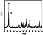
- FIG. 3 is an X-ray diffraction pattern of the positive electrode active material in Example 1-1 of the present application.
- a lithium-ion battery is used as an example of an electrochemical device to explain the present application, but the electrochemical device of the present application is not limited to the lithium-ion battery.
- the first aspect of the present application provides a positive electrode active material, wherein the cross section of the positive electrode active material includes a first region and a second region, the first region has a first structure of P63mc crystal phase structure, and the second region has a R- In the second structure of at least one crystal phase structure of 3m, P2/m or P-3m1, the area ratio of the first region to the second region is 1.8 to 5.4.
- the positive electrode active material provided by the present application includes both the first structure and the second structure.
- the thickness change rate of the positive electrode sheet refers to the thickness change rate of the positive electrode sheet during the cycle of the electrochemical device.
- the area ratio of the first region and the second region may be 1.8, 2, 2.5, 3, 3.5, 4, 4.5, 5, 5.4 or any range therebetween.
- the inventors of the present application have found that when the area ratio of the first region and the second region is too small (for example, less than 1.8), the structural stability of the positive electrode active material at high voltage is reduced, thereby affecting the performance of the electrochemical device. cycle performance.
- the area ratio of the first region and the second region is too large (for example, greater than 5.4), the volume expansion or shrinkage of the positive electrode active material in the lithium intercalation process increases, which affects the structural stability of the positive electrode sheet and the electrochemical device. Cycling performance at high voltage.
- the second region comprises F.
- the structural stability of the second structure (such as R-3m, etc.) under high voltage is not as good as that of the first structure with the P63mc crystal phase structure
- fluorine element by introducing fluorine element, its oxygen skeleton can be stabilized and the oxygen displacement can be reduced. phase transition, thereby reducing the risk of its premature degradation leading to a reduction in the overall performance of the cathode material.
- the atomic number ratio of F and O in the second region is 0.5% to 5%.
- the first region includes Co, and based on the moles of transition metal elements in the first region, the mole percentage C1 of Co in the first region is greater than or equal to 90%; for example, in the first region
- the molar percentage of Co can be 90%, 91%, 92%, 93%, 94%, 95%, 96%, 97%, 98%, 99%, or any range therebetween. In this case, while ensuring that the first region has better structural stability, it can further ensure that the first region has a higher capacity.
- the second region includes Co, and based on the moles of transition metal elements in the second region, the mole percentage of Co in the second region is greater than or equal to 70%.
- the mole percentage of Co in the second region can be 70%, 75%, 80%, 85%, 90%, 95%, or any range therebetween.
- ⁇ 25% at this time, the compatibility between the first region and the second region can be improved, thereby ensuring that the overall positive electrode active material is under high voltage structural stability.
- the first region includes element A and element M, based on the number of moles of element A in the first region, the mole percentage of element M is 0.1% to 10%, wherein element A includes Co , at least one of Mn or Ni; the element M includes at least one of Al, Ti, Ni, Nb, Mg, Ca, Zr, Zn, La, Y or Na.
- the second region includes element A and element T, and based on the moles of elements A and T in the second region, the mole percentage of element T is 0.1% to 1%, wherein element A includes At least one of Co, Mn or Ni; the element T includes at least one of S, Se, Si or C.
- the positive electrode active material satisfying at least one of the above-mentioned characteristics is beneficial to improving the structural stability of the positive electrode active material, thereby improving the cycle performance of the electrochemical device.
- the mole percentage of element M is 0.1%, 0.5%, 1%, 2%, 5%, 8%, or any range therebetween.
- the introduction of element M can form doping with Co, improve the stability of the first region structure, effectively improve the problem of the collapse of the first region structure during the process of lithium intercalation and deintercalation, thereby improving the stability of the overall structure of the positive electrode active material .
- the mole percentage of the element T is 0.1%, 0.3%, 0.5%, 0.7%, 0.8%, or any range therebetween.
- the introduction of element T can make up for some oxygen defects and improve the local structural stability; in addition, element T can be used as a sacrificial agent to preferentially consume active oxygen, thereby inhibiting the occurrence of uncontrollable oxidation reactions and improving System stability.
- the first region includes region A1 and region A2, the second region includes region B1, and region B1 is located between region A1 and region A2; ) is arranged between the region A1 and the region A2 with the P63mc crystal phase structure, on the one hand, it can form better protection for the region B1 with a less stable crystal phase structure, and reduce the risk of its phase transition under high voltage; on the other hand
- the region B1 can provide sufficient buffering effect for the regions A1 and A2 on both sides, reducing the overall expansion or contraction of the positive electrode material particles.
- the second region includes region B2, and the distance D between region B2 and the surface of the positive electrode active material satisfies, D ⁇ 200nm; there are regions with crystal phase structures such as R-3m in the near surface region of the positive electrode active material B2, the stress generated on the surface of the positive electrode active material due to the expansion of the first structure can be reduced, thereby reducing the risk of cracking of the particles of the positive electrode active material.
- the transition metal layers in the 3nm region of the interface layer are arranged in parallel; at this time, the interface compatibility between the first region and the second region is better, which can reduce the cracking between the first region and the second region during the expansion and contraction process risks of.
- the Dv50 of the positive electrode active material is 5 ⁇ m to 20 ⁇ m.
- the Dv50 of the positive electrode active material may be 5 ⁇ m, 8 ⁇ m, 10 ⁇ m, 12 ⁇ m, 15 ⁇ m, 17 ⁇ m, 20 ⁇ m or any range therebetween.
- the Dv50 of the positive electrode active material is within the above range, side reactions with the electrolyte can be reduced, and the cycle performance of the electrochemical device can be improved. At the same time, it can have sufficient active surface to ensure the kinetic performance of the electrochemical device.
- the intensity of the diffraction peak located in the range of 16° to 17.5° is I1
- the intensity of the diffraction peak located in the range of 44.5° to 45.5° is I2
- the intensity of the diffraction peak in the range of 17.5° to 19° is I3
- the intensity of the diffraction peak in the range of 49.5° to 50.5° is I4, satisfying: I1+I2>I3+I4.
- the crystal content of the first structure on the surface of the positive electrode active material is relatively high, which can improve the surface stability of the positive electrode active material particles.
- the diffraction peaks in the range of 16° to 17.5° and the diffraction peaks in the range of 44.5° to 45.5° are the diffraction peaks corresponding to the first structure
- the diffraction peaks in the range of 17.5° to 19° and the diffraction peaks in the range of 49.5° to 50.5° are Diffraction peaks corresponding to the second structure.
- satisfying: I2>I4 indicates that on the surface of the positive electrode active material, there are relatively many active crystal planes of the first structure, which can improve the stability of the active surface of the positive electrode active material.
- the preparation method of the positive electrode active material may include but not limited to the following steps: mixing the raw materials of the first structure, first passing through the common Prepare the first precursor by precipitation method; mix the raw materials of the second structure, and prepare the second precursor by co-precipitation method; and selectively calcinate the first precursor or the second precursor, and then mix and calcinate to obtain the positive electrode active material .
- the present application has no special limitation on the calcination temperature and time for obtaining the first precursor or the second precursor, as long as the purpose of the present application can be achieved, for example, the calcination temperature is 500-1100°C, and the calcination time is 1-12h.
- the present application has no special limitation on the temperature and time of calcination after mixing the first precursor and the second precursor, as long as the purpose of the present application can be achieved, for example, the calcination temperature is 500-1100°C, and the calcination time is 1-12h.
- raw materials for the first structure may include, but are not limited to, Co(NO 3 ) 2 , Ni(NO 3 ) 2 , CoCl 2 , CoSO 4 , Co(CH 3 COO) 2 , NiCl 2 , NiSO 4 , or Ni(CH 3 COO) at least one of 2 .
- raw materials for the second structure may include, but are not limited to, Co(NO 3 ) 2 , MnSO 4 , Ni 2 SO 4 , CoCl 2 , CoSO 4 , Co(CH 3 COO) 2 , NiCl 2 , NiSO 4 , Ni(CH At least one of 3 COO) 2 , Ni(NO 3 ) 2 , MnCl 2 , MnSO 4 , Mn(CH 3 COO) 2 or Mn(NO 3 ) 2 .
- the present application has no special restrictions on the method of introducing the above-mentioned element M or element T into the positive electrode active material, as long as the purpose of the application can be achieved, for example, the compound containing element M is added as the raw material of the first structure and then the first Precursor, or add it when calcining the first precursor; add the compound containing element T as the raw material of the second structure and then prepare the second precursor, or add it when calcining the second precursor.
- the present application has no particular limitation on the compound containing the element M and the compound containing the element T, as long as the purpose of the present application can be achieved.
- compounds containing the element M may include, but are not limited to, Al(NO 3 ) 3 , TiO 2 , Al 2 O 3 , MgO, Y 2 O 3 , La 2 O 3 , Nb 2 O 5 or W 2 O 3 at least one.
- the compound containing the element T may include, but not limited to, at least one of NH 4 F, Se powder, or S powder.
- the positive electrode active material includes Li x Na z Co 1-y X y O 2- ⁇ R ⁇ , wherein the element X includes Mn, Ni, Nb, B, Mg, Al, Si, P, S, Ti , at least one of Cr, Fe, Cu, Zn, Ga, Y, Zr, Mo, Ag, W, In, Sn, Pb, Sb, Se or Ce, R is halogen, 0.6 ⁇ x ⁇ 1.2, 0 ⁇ y ⁇ 0.15, 0 ⁇ z ⁇ 0.03, 0 ⁇ 0.1.
- the second aspect of the present application provides a positive electrode sheet, which includes the positive electrode active material in any one of the foregoing embodiments.
- the positive electrode active material provided by the present application has relatively low volume expansion or contraction during the lithium intercalation process, so that the positive electrode sheet provided by the present application has a low thickness change rate during the cycle of the electrochemical device.
- the positive electrode sheet includes a positive electrode material layer, a positive electrode collector, and an intermediate layer between the positive electrode material layer and the positive electrode collector, the positive electrode material layer includes a positive electrode active material, and the intermediate layer and the positive electrode collector
- the peeling force between them is F1
- the peeling force between the positive electrode material layer and the intermediate layer is F2, satisfying that the smaller of F1 and F2 is greater than or equal to 10N/m.
- the smaller of F1 and F2 is greater than or equal to 20N/m, the smaller of the peeling force F1 between the intermediate layer and the positive electrode current collector and the peeling force F2 between the positive electrode material layer and the intermediate layer is in the above Within the range, it shows that there is good adhesion between the positive electrode material layer and the intermediate layer, which can reduce the risk of the positive electrode material layer falling off the surface of the current collector, and is conducive to improving the structural stability of the positive electrode sheet, thereby facilitating the improvement of electrochemical devices. cycle performance.
- the intermediate layer includes a binder and a conductive agent, and based on the quality of the intermediate layer, the mass percentage of the binder is 20% to 80%; for example, the mass percent of the binder It can be 30%, 35%, 40%, 45%, 50%, 55%, 60%, 75%, 70%, 75%, or any range therebetween.
- the mass percentage of the binder is 20% to 80%; for example, the mass percent of the binder It can be 30%, 35%, 40%, 45%, 50%, 55%, 60%, 75%, 70%, 75%, or any range therebetween.
- the binder may include but not limited to polyvinylidene fluoride, copolymer of vinylidene fluoride-hexafluoropropylene, polyamide , polyacrylonitrile, polyacrylate, polyacrylic acid, polyacrylate, polyvinylpyrrolidone, polyvinyl ether, polymethyl methacrylate, polytetrafluoroethylene or polyhexafluoropropylene.
- the intermediate layer includes a conductive agent to facilitate electron conduction between the positive electrode material layer and the positive electrode current collector layer.
- the present application is not particularly limited to the conductive agent, as long as the purpose of the application can be realized, for example, it can include but not limited to conductive carbon black (Super P), carbon nanotubes (CNTs), carbon fiber, flake graphite, Ketjen black, graphene , at least one of metallic materials or conductive polymers.
- the aforementioned carbon nanotubes may include, but are not limited to, single-walled carbon nanotubes and/or multi-walled carbon nanotubes.
- the aforementioned carbon fibers may include, but are not limited to, vapor grown carbon fibers (VGCF) and/or carbon nanofibers.
- the above metal material may include but not limited to metal powder and/or metal fiber, specifically, the metal may include but not limited to at least one of copper, nickel, aluminum or silver.
- the aforementioned conductive polymer may include but not limited to at least one of polyphenylene derivatives, polyaniline, polythiophene, polyacetylene or polypyrrole.
- the thickness of the positive electrode material layer is T1
- the thickness of the intermediate layer is T2, satisfying: 10 ⁇ T1/T2 ⁇ 60.
- the present application has no special limitation on the thickness T1 of the positive electrode material layer and the thickness T2 of the intermediate layer, as long as the purpose of the present application can be achieved, for example, the thickness T1 of the positive electrode material layer is 40 ⁇ m to 60 ⁇ m, and the thickness T2 of the intermediate layer is 1 ⁇ m to 4 ⁇ m.
- the thickness T1 of the positive electrode material layer and the thickness T2 of the intermediate layer within the above range, it is beneficial to obtain a positive electrode sheet with good structural stability, thereby improving the cycle performance of the electrochemical device.
- the preparation method of the positive electrode sheet may include but not limited to the following steps: coating the slurry of the intermediate layer on the positive electrode assembly One surface of the fluid, after the drying treatment, the slurry of the positive electrode material layer is continued to be coated on the intermediate layer, and the positive electrode sheet with the intermediate layer and the positive electrode material layer coated on one side is obtained after the drying treatment. Repeat the above steps to obtain a positive electrode sheet coated with an intermediate layer and a positive electrode material layer on both sides.
- the above-mentioned "surface” may be the entire area of the positive electrode current collector, or a partial area of the positive electrode current collector. This application is not particularly limited, as long as the purpose of this application can be achieved.
- the third aspect of the present application provides an electrochemical device, which includes the positive electrode active material in any of the foregoing embodiments or includes the positive electrode sheet in any of the foregoing embodiments.
- the positive electrode active material provided by the present application has a low volume expansion rate in the process of lithium intercalation and deintercalation, and the positive electrode sheet provided by the present application has good structural stability, so that the electrochemical device provided by the present application has good cycle performance.
- the electrochemical device of the present application also includes a negative electrode sheet.
- the negative electrode sheet usually includes a negative electrode collector and a negative electrode material layer arranged on the surface of the negative electrode collector.
- the application has no special restrictions on the negative electrode collector, as long as the purpose of the application can be achieved.
- it may include but not limited to copper foil, copper alloy foil, nickel foil, stainless steel foil, titanium foil, nickel foam, copper foam or composite current collectors.
- the thickness of the negative electrode collector there is no particular limitation on the thickness of the negative electrode collector, as long as the purpose of the present application can be achieved, for example, the thickness is 4 ⁇ m to 12 ⁇ m.
- the negative electrode material layer may be provided on one surface in the thickness direction of the negative electrode current collector, or on two surfaces in the thickness direction of the negative electrode current collector. It should be noted that the "surface” here may be the entire area of the negative electrode collector, or a partial area of the negative electrode collector. This application is not particularly limited, as long as the purpose of this application can be achieved.
- the negative electrode material layer includes negative electrode active materials, wherein the negative electrode active material is not particularly limited, as long as the purpose of the application can be achieved, for example, it can include but not limited to natural graphite, artificial graphite, mesophase micro carbon spheres, hard Carbon, soft carbon, silicon, silicon-carbon composite, Li-Sn alloy, Li-Sn-O alloy, Sn, SnO, SnO 2 , lithiated TiO 2 -Li 4 Ti 5 O 12 or Li with spinel structure - at least one of Al alloys.
- the negative electrode active material is not particularly limited, as long as the purpose of the application can be achieved, for example, it can include but not limited to natural graphite, artificial graphite, mesophase micro carbon spheres, hard Carbon, soft carbon, silicon, silicon-carbon composite, Li-Sn alloy, Li-Sn-O alloy, Sn, SnO, SnO 2 , lithiated TiO 2 -Li 4 Ti 5 O 12 or Li with spinel structure
- the negative electrode material layer may also include a conductive agent.
- the present application has no special limitation on the conductive agent, as long as the purpose of the present application can be achieved, for example, it may include but not limited to at least one of the above-mentioned conductive agents.
- the negative electrode material layer may also include a binder, and the present application has no special restrictions on the binder, as long as the purpose of the application can be achieved, for example, it may include but not limited to at least one of the above-mentioned binders .
- the negative electrode sheet may further include a conductive layer, and the conductive layer is located between the negative electrode current collector and the negative electrode material layer.
- the present application has no particular limitation on the composition of the conductive layer, which may be a commonly used conductive layer in the field, and the conductive layer may include but not limited to the above-mentioned conductive agent and the above-mentioned binder.
- the electrochemical device of the present application also includes a separator, which is not particularly limited in the present application, as long as the purpose of the application can be achieved, such as but not limited to polyethylene (PE), polypropylene (PP), polytetrafluoroethylene Ethylene-based polyolefin (PO) separator, polyester film (such as polyethylene terephthalate (PET) film), cellulose film, polyimide film (PI), polyamide film (PA) , spandex, aramid film, woven film, nonwoven film (non-woven fabric), microporous film, composite film, separator paper, rolled film or spinning film, preferably PP.
- a separator which is not particularly limited in the present application, as long as the purpose of the application can be achieved, such as but not limited to polyethylene (PE), polypropylene (PP), polytetrafluoroethylene Ethylene-based polyolefin (PO) separator, polyester film (such as polyethylene terephthalate (PET) film),
- the separator of the present application may have a porous structure, and the pore size is not particularly limited as long as the purpose of the present application can be achieved, for example, the pore size may be 0.01 ⁇ m to 1 ⁇ m.
- the thickness of the isolation film is not particularly limited, as long as the purpose of the present application can be achieved, for example, the thickness may be 5 ⁇ m to 500 ⁇ m.
- a separator may include a substrate layer and a surface treatment layer.
- the substrate layer can be a non-woven fabric, film or composite film with a porous structure, and the material of the substrate layer can include but not limited to polyethylene, polypropylene, polyethylene terephthalate or polyimide at least one.
- a polypropylene porous film, a polyethylene porous film, a polypropylene non-woven fabric, a polyethylene non-woven fabric, or a polypropylene-polyethylene-polypropylene porous composite film may be used.
- at least one surface of the substrate layer is provided with a surface treatment layer, and the surface treatment layer may be a polymer layer or an inorganic layer, or a layer formed by mixing a polymer and an inorganic material.
- the inorganic material layer may include but not limited to inorganic particles and inorganic material layer binder.
- the application has no special limitation on the inorganic particles, as long as the purpose of the application can be achieved.
- it may include but not limited to alumina, silicon oxide, Magnesium oxide, titanium oxide, hafnium oxide, tin oxide, cerium oxide, nickel oxide, zinc oxide, calcium oxide, zirconium oxide, yttrium oxide, silicon carbide, boehmite, aluminum hydroxide, magnesium hydroxide, calcium hydroxide or at least one of barium sulfate.
- the present application has no particular limitation on the inorganic layer binder, for example, it may include but not limited to polyvinylidene fluoride, copolymer of vinylidene fluoride-hexafluoropropylene, polyamide, polyacrylonitrile, polyacrylate, polyacrylic acid, At least one of polyacrylate, polyvinylpyrrolidone, polyvinyl ether, polymethylmethacrylate, polytetrafluoroethylene or polyhexafluoropropylene.
- polyvinylidene fluoride copolymer of vinylidene fluoride-hexafluoropropylene
- polyamide polyacrylonitrile
- polyacrylate polyacrylic acid
- the polymer layer contains a polymer, and the polymer material may include but not limited to polyamide, polyacrylonitrile, acrylate polymer, polyacrylic acid, polyacrylate, polyvinyl pyrrolidone, polyvinyl ether, polyvinylidene fluoride At least one of ethylene or poly(vinylidene fluoride-hexafluoropropylene).
- the electrochemical device of the present application also includes an electrolyte, which is not particularly limited in the present application, as long as the purpose of the present application can be achieved, for example, the electrolyte may include a non-aqueous solvent and a lithium salt.
- the present application has no special limitation on the non-aqueous solvent, as long as the purpose of the present application can be achieved, for example, it may include but not limited to at least one of carbonate compounds, carboxylate compounds, ether compounds or other organic solvents.
- the above-mentioned carbonate compound may include but not limited to at least one of a chain carbonate compound, a cyclic carbonate compound or a fluorocarbonate compound.
- Above-mentioned chain carbonate compound can include but not limited to dimethyl carbonate (DMC), diethyl carbonate (DEC), dipropyl carbonate (DPC), methyl propyl carbonate (MPC), ethylene propyl carbonate (EPC) or at least one of methyl ethyl carbonate (MEC).
- the above-mentioned cyclic carbonate may include but not limited to at least one of ethylene carbonate (EC), propylene carbonate (PC), butylene carbonate (BC) or vinylethylene carbonate (VEC).
- Fluorocarbonate compounds may include, but are not limited to, fluoroethylene carbonate (FEC), 1,2-difluoroethylene carbonate, 1,1-difluoroethylene carbonate, 1,1,2-trifluoroethylene carbonate Ethylene carbonate, 1,1,2,2-tetrafluoroethylene carbonate, 1-fluoro-2-methylethylene carbonate, 1-fluoro-1-methylethylene carbonate, 1,2- At least one of difluoro-1-methylethylene carbonate, 1,1,2-trifluoro-2-methylethylene carbonate, or trifluoromethylethylene carbonate.
- FEC fluoroethylene carbonate
- 1,2-difluoroethylene carbonate 1,1-difluoroethylene carbonate
- carboxylate compounds may include but are not limited to methyl formate, methyl acetate, ethyl acetate, n-propyl acetate, tert-butyl acetate, methyl propionate, ethyl propionate, propyl propionate, ⁇ -butyl At least one of lactone, decanolactone, valerolactone, mevalonolactone or caprolactone.
- the aforementioned ether compounds may include, but are not limited to, dibutyl ether, tetraglyme, diglyme, 1,2-dimethoxyethane, 1,2-diethoxyethane, ethoxy At least one of methoxyethane, 2-methyltetrahydrofuran or tetrahydrofuran.
- the above-mentioned other organic solvents may include but not limited to dimethyl sulfoxide, 1,2-dioxolane, sulfolane, methyl sulfolane, 1,3-dimethyl-2-imidazolidinone, N-methyl-2- At least one of pyrrolidone, formamide, dimethylformamide, acetonitrile, trimethyl phosphate, triethyl phosphate, trioctyl phosphate or phosphoric acid ester.
- This application has no special restrictions on lithium salts, as long as the purpose of this application can be achieved, for example, it may include but not limited to LiPF 6 , LiBF 4 , LiAsF 6 , LiClO 4 , LiB(C 6 H 5 ) 4 , LiCH 3 SO 3. At least one of LiCF 3 SO 3 , LiN(SO 2 CF 3 ) 2 , LiC(SO 2 CF 3 ) 3 , LiSiF 6 , LiBOB or lithium difluoroborate.
- the lithium salt comprises LiPF 6 .
- the electrochemical device of the present application is not particularly limited, and it may include any device that undergoes an electrochemical reaction.
- the electrochemical device may include, but is not limited to, a lithium metal secondary battery, a lithium ion secondary battery (lithium ion battery), a lithium polymer secondary battery, or a lithium ion polymer secondary battery, among others.
- the preparation process of electrochemical devices is well known to those skilled in the art, and the present application is not particularly limited.
- it may include but not limited to the following steps: stack the positive electrode sheet, separator and negative electrode sheet in sequence, and as required Winding, folding and other operations to obtain the electrode assembly with a winding structure, put the electrode assembly into the packaging bag, inject the electrolyte solution into the packaging bag and seal it to obtain an electrochemical device; or, put the positive electrode sheet, separator and negative electrode
- the pole pieces are stacked in order, and then the four corners of the entire laminated structure are fixed with adhesive tape to obtain the electrode assembly of the laminated structure.
- the electrode assembly is placed in the packaging bag, and the electrolyte is injected into the packaging bag and sealed to obtain an electrochemical device.
- overcurrent prevention elements, guide plates, etc. can also be placed in the packaging bag as needed, so as to prevent pressure rise and overcharge and discharge inside the electrochemical device.
- a fourth aspect of the present application provides an electronic device, which includes the electrochemical device in any one of the foregoing embodiments.
- the electrochemical device provided by the present application has good cycle performance, so the electronic device provided by the present application has a long service life.
- the electronic device of the present application is not particularly limited, and it may be used in any electronic device known in the prior art.
- electronic devices may include, but are not limited to, notebook computers, pen-based computers, mobile computers, e-book players, cellular phones, portable fax machines, portable copiers, portable printers, headsets, VCRs, LCD TVs, portable cleaners, portable CD players, mini discs, transceivers, electronic organizers, calculators, memory cards, portable tape recorders, radios, backup power supplies, motors, cars, motorcycles, power-assisted bicycles, bicycles, Lighting appliances, toys, game consoles, clocks, electric tools, flashlights, cameras, large household storage batteries and lithium-ion capacitors, etc.
- An inductively coupled plasma spectrometer was used to test the contents of different elements in the positive electrode active material.
- the lithium-ion battery is fully placed below 3.5V under the current density of 30mA/cm 2 , and after standing for 10min, the positive pole piece is disassembled in the glove box; the positive pole piece is transferred to a scanning electron microscope equipped with a focused ion beam (Model: FEI Vion Plasma FIB) cavity, processing samples that can be used for transmission scanning electron microscope (STEM, model: FEI Titan3 G2 60-300) analysis, the surface of the sample is required to be protected by Pt, and processed with Ga ion beam, the thickness of the sample is not More than 100nm; and cleaning in low voltage mode to remove residual surface of sample processing.
- the sample is observed under STEM, and the X-ray energy spectrum analysis (EDS) function is used to collect data at a suitable magnification to obtain the element content in the first region or the second region of the positive electrode active material. Collect at least 3 different locations and take the average as the final result.
- EDS X-ray energy spectrum analysis
- the surface interface cutting and stretching system (model: Model: SAICAS-DN) is used for testing; first take a flat pole piece of 2cm ⁇ 0.5cm, place it on the sample stage in the instrument cavity, and fix the bottom. Then the blade moves at a speed of 0.2 mm/min, reads the measured value, and determines the smaller one between the peeling force F1 between the intermediate layer and the positive electrode current collector and the peeling force F2 between the positive electrode material layer and the intermediate layer as Peel force F.
- FIG. 1 it is a scanning electron micrograph of the positive electrode active material in Example 1-1. It can be seen from the figure that the particles of the positive electrode active material in Example 1-1 are mainly in the form of flakes.
- Fig. 2 is the transmission electron microscope photograph of the particle cross section of positive electrode active material in the embodiment 1-1, wherein, the crystal phase structure of area A1 and area A2 is P63mc, the crystal phase structure of area B1 is R-3m, it can be seen that the area B1 is located between area A1 and area A2, and there is an interface layer between area B1 and area A1 and area A2, along the direction perpendicular to the interface layer between area B1 and area A1, in the area 3nm away from the interface layer in area B1 The transition metal layer in the region A1 and the transition metal layer in the region 3 nm away from the interface layer are arranged in parallel.
- the region B1 includes a region whose distance from the surface of the positive electrode active material is less than or equal to 200 nm, thereby reducing the stress on the surface of the positive electrode active material due to the expansion or contraction of the first structure, thereby reducing the risk of breaking the positive electrode active material particles.
- FIG 3 it is the X-ray diffraction spectrum of the positive electrode active material in embodiment 1-1, and the intensity I1 of the diffraction peak of 16 ° to 17.5 ° range is 100, and the intensity I2 of the diffraction peak of 44.5 ° to 45.5 ° range
- the intensity I3 of the diffraction peak in the range of 17.5° to 19° is 30, and the intensity I3 of the diffraction peak in the range of 49.5° to 50.5° is 23, satisfying: I1+I2>I3+I4. At the same time, I2>I4.
- the negative active material artificial graphite Mix the negative active material artificial graphite, the binder styrene-butadiene rubber (SBR), and the thickener sodium carboxymethylcellulose (CMC) according to the mass ratio of 97:2:1, add deionized water, and work in a vacuum mixer Stir evenly to obtain the negative electrode slurry, wherein the solid content of the negative electrode slurry is 75%.
- Copper foil is used as the negative electrode collector, the negative electrode slurry is evenly coated on the negative electrode collector, and the negative electrode sheet is obtained after drying, cold pressing and cutting.
- a porous PE film with a thickness of 7 ⁇ m was used.
- the above-prepared positive electrode sheet, separator, and negative electrode sheet are stacked in sequence, and wound to obtain an electrode assembly.
- Example 1-2 and Example 1-3 except that Co, Mn and Ni molar ratio are adjusted to 90:5:5, 70:15:15 respectively in the step (2) of ⁇ preparation of positive electrode active material> , and the rest are identical to Example 1-1.
- Example 1-5 in addition to adjusting the mass ratios of the first precursor and the second precursor to 1.5:1 and 4.5:1 respectively in step (3) of ⁇ Preparation of Positive Electrode Active Material> Other than that, the others are the same as in Example 1-1.
- Example 2-1 except that an intermediate layer is first coated on the surface of the positive electrode collector according to the following steps, the rest is the same as that of Example 1-1.
- the binder PVDF, conductive carbon black (Super P), and carbon nanotubes (CNT) were mixed according to a mass ratio of 35:55:10, NMP was added, and stirred evenly under the action of a vacuum mixer to obtain a middle layer slurry.
- the intermediate layer slurry is uniformly coated on the surface of the positive electrode current collector, and the coating amount is 0.002 mg/mm 2 , and the intermediate layer is formed on the surface of the positive electrode current collector after drying.
- the thickness of the positive electrode material layer in the positive electrode sheet is 54 ⁇ m, and the thickness of the intermediate layer is 1 ⁇ m.
- Example 2-2 except that the mass ratios of binder PVDF, conductive carbon black (Super P), and carbon nanotubes (CNT) are 60:35:5, the thickness of the positive electrode material layer is 42 ⁇ m, and the thickness of the intermediate layer is 3 ⁇ m Other than that, the others are the same as in Example 2-1.
- Example 2-3 except that the mass ratio of binder PVDF, conductive carbon black (Super P), and carbon nanotube (CNT) is 60:35:5, the thickness of the positive electrode material layer is 42 ⁇ m, and the thickness of the intermediate layer is 2 ⁇ m Other than that, the others are the same as in Example 2-1.
- Example 3-1 to Example 3-4 except that the NH 4 F added in the step (2) of ⁇ Preparation of Positive Electrode Active Material> is 1%, 0.6%, 6%, and 10% of Co molar amounts respectively, The rest are the same as in Example 1-1.
- Example 4-1 except that steps (1) and (2) in ⁇ Preparation of Positive Electrode Active Material> are carried out according to the following steps, all the other are the same as Example 1-1:
- the calcination temperature is 600°C and the calcination time is 3h.
- the mole percent content of Ti in TiO2 is 0.1% based on the total moles of Co and Ni.
- Example 4-2 except that the molar ratio of Co, Ni and Al in step (1) of ⁇ Preparation of Positive Electrode Active Material> is 95:5:0.1, the rest is the same as Example 3-1.
- Example 4-3 except that the molar ratio of Co, Ni and Al in step (1) of ⁇ Preparation of Positive Electrode Active Material> is 95:5:10, the rest is the same as Example 3-1.
- Example 4-4 except that Se in the total molar amount of Co, Mn and Ni is added in step (2) of ⁇ Preparation of Positive Electrode Active Material>, the rest is the same as Example 3-1.
- Example 4-5 except that Se in the total molar mass of Co, Mn and Ni was added in step (2) of ⁇ Preparation of Positive Electrode Active Material>, the rest was the same as Example 3-1.
- Example 1-1 In Comparative Example 1-2, except that the first precursor prepared by step (1) was used in ⁇ Preparation of positive electrode active material> to prepare the positive electrode active material according to the following steps, the rest were the same as in Example 1-1:
- the first precursor was mixed with Na 2 CO 3 at a transition metal to Na molar ratio of 1:1.05, and then calcined in an air atmosphere to obtain an intermediate product.
- the calcination temperature was 1000°C
- the calcination time was 12 h
- the air flow rate was 8 L/ min.
- the intermediate product and lithium nitrate were mixed uniformly according to the mass ratio of 1:3, and reacted at 260°C for 6 hours, then washed with water and dried, and the product was ground and sieved to obtain the positive electrode active material.
- Example 1-1 to Example 1-4 when C1-C2 ⁇ 25%, the obtained lithium ion battery has better cycle performance.
- the possible reason is that the difference in Co content between the first region and the second region is small, which can improve the compatibility between the first region and the second region, thereby ensuring the overall structural stability of the positive electrode active material under high voltage. sex.
- Example 1-1 From Example 1-1, Example 2-1 to Example 2-3, it can be seen that when the peeling force between the intermediate layer and the positive electrode current collector and the peeling force between the positive electrode material layer and the intermediate layer are smaller When F is greater than or equal to 20N/m, there is stronger cohesive force between the intermediate layer in the positive electrode sheet and the positive electrode current collector and the positive electrode material layer, which can further improve the stability of the positive electrode material layer in the positive electrode sheet. Thereby improving the cycle performance of lithium-ion batteries.
- Example 3-1 to Example 3-4 From Example 1-1, Example 3-1 to Example 3-4, it can be seen that the atomic number ratio of F and O in the second region has more excellent cycle stability in the range of 0.5% to 5%, which is due to The structural stability of the second structure (such as R-3m, etc.) under high voltage is not as good as that of the first structure with the P63mc crystal phase structure.
- fluorine By introducing fluorine, it can stabilize its oxygen skeleton and reduce the phase transition caused by oxygen displacement, thereby reducing the Its premature degradation leads to the risk of lower overall performance of the cathode active material.
- Example 4-1 to Example 4-5 From Example 1-1, Example 4-1 to Example 4-5, it can be seen that the element M (such as Al, Ti) is further doped in the first structure, and the element T (such as Al, Ti) is doped in the second structure. Se), which can further improve the structural stability of the first structure and the second structure under high voltage, thereby improving the high-voltage cycle performance of the lithium-ion battery.
- element M such as Al, Ti
- T such as Al, Ti
Landscapes
- Chemical & Material Sciences (AREA)
- Chemical Kinetics & Catalysis (AREA)
- Electrochemistry (AREA)
- General Chemical & Material Sciences (AREA)
- Organic Chemistry (AREA)
- Inorganic Chemistry (AREA)
- Engineering & Computer Science (AREA)
- Composite Materials (AREA)
- Materials Engineering (AREA)
- Manufacturing & Machinery (AREA)
- Battery Electrode And Active Subsutance (AREA)
- Secondary Cells (AREA)
Abstract
Description


Claims (12)
- 一种正极活性材料,其中,所述正极活性材料的截面中包括第一区域和第二区域,所述第一区域具有P63mc晶相结构的第一结构,所述第二区域具有R-3m、P2/m或P-3m1中的至少一种晶相结构的第二结构,所述第一区域和所述第二区域的面积比为1.8至5.4。
- 根据权利要求1所述的正极活性材料,其中,所述第二区域包含F元素,所述第二区域中F元素与O元素的原子数比为0.5%至5%。
- 根据权利要求1所述的正极活性材料,其中,所述正极活性材料满足以下特征中的至少一者:(i)所述第一区域包括Co,基于所述第一区域中过渡金属元素的摩尔数,所述第一区域中Co的摩尔百分含量C1大于或等于90%;(ii)所述第二区域包括Co,基于所述第二区域中过渡金属元素的摩尔数,所述第二区域中Co的摩尔百分含量C2大于或等于70%;(iii)所述第一区域包括元素A和元素M,基于第一区域中元素A的摩尔数,元素M的摩尔百分含量为0.1%至10%,其中,所述元素A包括Co、Mn或Ni中的至少一种;所述元素M包括Al、Ti、Ni、Nb、Mg、Ca、Zr、Zn、La、Y或Na中的至少一种;(iv)所述第二区域包括元素A和元素T,基于第二区域中元素A的摩尔数,元素T的摩尔百分含量为0.1%至1%,其中,所述元素A包括Co、Mn或Ni中的至少一种;所述元素T包括S、Se、Si或C中的至少一种。
- 根据权利要求3所述的正极活性材料,其中,|C1-C2|≤25%。
- 根据权利要求1所述的正极活性材料,其中,所述正极活性材料满足以下特征中的至少一者:(v)所述第一区域包括区域A1和区域A2,所述第二区域包括区域B1,所述区域B1位于所述区域A1和所述区域A2之间;(vi)所述第二区域包括区域B2,所述区域B2与所述正极活性材料表面的距离D满足,D≤200nm;(vii)所述第一区域和所述第二区域之间具有界面层,沿垂直所述界面层的方向,所述第一区域中距离所述界面层3nm的区域中的过渡金属层和所述第二区域中距离所述界面层3nm的区域中的过渡金属层呈平行排列;(viii)所述正极活性材料的Dv50为5μm至20μm。
- 根据权利要求1所述的正极活性材料,其中,在所述正极活性材料的XRD谱图中,位于16°至17.5°范围的衍射峰的强度为I1,位于44.5°至45.5°范围的衍射峰的强度为I2;位于17.5°至19°范围的衍射峰的强度为I3,位于49.5°至50.5°范围的衍射峰的强度为I4,满足:I1+I2>I3+I4。
- 根据权利要求6所述的正极活性材料,其中,I2>I4。
- 一种正极极片,其包括权利要求1至7中任一项所述的正极活性材料。
- 根据权利要求8所述的正极极片,所述正极极片包括正极材料层、正极集流体和位于所述正极材料层和所述正极集流体之间的中间层,所述正极材料层包括所述正极活性材料,所述中间层与所述正极集流体之间的剥离力为F1,所述正极材料层与所述中间层之间的剥离力为F2,满足:F1和F2中的较小者大于或等于20N/m。
- 根据权利要求9所述的正极极片,其中,所述正极极片满足以下特征中的至少一者:(xi)所述中间层包括粘结剂和导电剂,基于所述中间层的质量,所述粘结剂的质量百分含量为20%至80%;(xii)所述正极材料层的厚度为T1,所述中间层的厚度为T2,满足10≤T1/T2≤60。
- 一种电化学装置,其包括权利要求1至7中任一项所述的正极活性材料或权利要求8至10中任一项所述的正极极片。
- 一种电子装置,其包括权利要求11所述的电化学装置。
Priority Applications (4)
| Application Number | Priority Date | Filing Date | Title |
|---|---|---|---|
| EP21962890.6A EP4428953A4 (en) | 2021-11-04 | 2021-11-04 | POSITIVE ELECTRODE ACTIVE MATERIAL, POSITIVE ELECTRODE PLATE, ELECTROCHEMICAL APPARATUS COMPRISING A POSITIVE ELECTRODE PLATE, AND ELECTRONIC APPARATUS |
| PCT/CN2021/128772 WO2023077373A1 (zh) | 2021-11-04 | 2021-11-04 | 正极活性材料、正极极片、包含该正极极片的电化学装置和电子装置 |
| CN202180013380.0A CN115104204A (zh) | 2021-11-04 | 2021-11-04 | 正极活性材料、正极极片、包含该正极极片的电化学装置和电子装置 |
| US18/654,440 US20240282940A1 (en) | 2021-11-04 | 2024-05-03 | Positive active material, positive electrode plate and electrochemical device containing same, and electronic device |
Applications Claiming Priority (1)
| Application Number | Priority Date | Filing Date | Title |
|---|---|---|---|
| PCT/CN2021/128772 WO2023077373A1 (zh) | 2021-11-04 | 2021-11-04 | 正极活性材料、正极极片、包含该正极极片的电化学装置和电子装置 |
Related Child Applications (1)
| Application Number | Title | Priority Date | Filing Date |
|---|---|---|---|
| US18/654,440 Continuation US20240282940A1 (en) | 2021-11-04 | 2024-05-03 | Positive active material, positive electrode plate and electrochemical device containing same, and electronic device |
Publications (1)
| Publication Number | Publication Date |
|---|---|
| WO2023077373A1 true WO2023077373A1 (zh) | 2023-05-11 |
Family
ID=83287687
Family Applications (1)
| Application Number | Title | Priority Date | Filing Date |
|---|---|---|---|
| PCT/CN2021/128772 Ceased WO2023077373A1 (zh) | 2021-11-04 | 2021-11-04 | 正极活性材料、正极极片、包含该正极极片的电化学装置和电子装置 |
Country Status (4)
| Country | Link |
|---|---|
| US (1) | US20240282940A1 (zh) |
| EP (1) | EP4428953A4 (zh) |
| CN (1) | CN115104204A (zh) |
| WO (1) | WO2023077373A1 (zh) |
Cited By (1)
| Publication number | Priority date | Publication date | Assignee | Title |
|---|---|---|---|---|
| CN119314999A (zh) * | 2023-07-11 | 2025-01-14 | 宁德时代新能源科技股份有限公司 | 正极极片、电池以及用电设备 |
Families Citing this family (2)
| Publication number | Priority date | Publication date | Assignee | Title |
|---|---|---|---|---|
| WO2024197436A1 (zh) * | 2023-03-24 | 2024-10-03 | 宁德新能源科技有限公司 | 正极材料、包含该正极材料的电化学装置和电子装置 |
| CN121241450A (zh) * | 2023-05-09 | 2025-12-30 | 宁德新能源科技有限公司 | 正极材料、电化学装置和电子装置 |
Citations (5)
| Publication number | Priority date | Publication date | Assignee | Title |
|---|---|---|---|---|
| CN101541684A (zh) * | 2006-09-12 | 2009-09-23 | 住友化学株式会社 | 锂复合金属氧化物及非水电解质二次电池 |
| JP2010129509A (ja) * | 2008-12-01 | 2010-06-10 | Sanyo Electric Co Ltd | 非水電解質電池 |
| CN112670492A (zh) * | 2020-12-23 | 2021-04-16 | 宁德新能源科技有限公司 | 正极材料及其制备方法以及电化学装置 |
| CN112768645A (zh) * | 2019-10-21 | 2021-05-07 | 丰田自动车株式会社 | 正极活性物质的制造方法和锂离子电池的制造方法 |
| CN112758989A (zh) * | 2019-10-21 | 2021-05-07 | 丰田自动车株式会社 | 正极活性物质的制造方法和锂离子电池的制造方法 |
Family Cites Families (3)
| Publication number | Priority date | Publication date | Assignee | Title |
|---|---|---|---|---|
| CN102610806B (zh) * | 2012-02-27 | 2014-11-12 | 宁德新能源科技有限公司 | 一种锂离子电池及其正极活性材料 |
| JP2016027530A (ja) * | 2012-11-29 | 2016-02-18 | 三洋電機株式会社 | 非水電解質二次電池 |
| CN112103509B (zh) * | 2020-08-20 | 2023-06-06 | 欣旺达电动汽车电池有限公司 | 正极集流体、正极片、锂离子电池及电池模组 |
-
2021
- 2021-11-04 EP EP21962890.6A patent/EP4428953A4/en active Pending
- 2021-11-04 CN CN202180013380.0A patent/CN115104204A/zh active Pending
- 2021-11-04 WO PCT/CN2021/128772 patent/WO2023077373A1/zh not_active Ceased
-
2024
- 2024-05-03 US US18/654,440 patent/US20240282940A1/en active Pending
Patent Citations (5)
| Publication number | Priority date | Publication date | Assignee | Title |
|---|---|---|---|---|
| CN101541684A (zh) * | 2006-09-12 | 2009-09-23 | 住友化学株式会社 | 锂复合金属氧化物及非水电解质二次电池 |
| JP2010129509A (ja) * | 2008-12-01 | 2010-06-10 | Sanyo Electric Co Ltd | 非水電解質電池 |
| CN112768645A (zh) * | 2019-10-21 | 2021-05-07 | 丰田自动车株式会社 | 正极活性物质的制造方法和锂离子电池的制造方法 |
| CN112758989A (zh) * | 2019-10-21 | 2021-05-07 | 丰田自动车株式会社 | 正极活性物质的制造方法和锂离子电池的制造方法 |
| CN112670492A (zh) * | 2020-12-23 | 2021-04-16 | 宁德新能源科技有限公司 | 正极材料及其制备方法以及电化学装置 |
Non-Patent Citations (1)
| Title |
|---|
| See also references of EP4428953A4 * |
Cited By (1)
| Publication number | Priority date | Publication date | Assignee | Title |
|---|---|---|---|---|
| CN119314999A (zh) * | 2023-07-11 | 2025-01-14 | 宁德时代新能源科技股份有限公司 | 正极极片、电池以及用电设备 |
Also Published As
| Publication number | Publication date |
|---|---|
| EP4428953A1 (en) | 2024-09-11 |
| CN115104204A (zh) | 2022-09-23 |
| EP4428953A4 (en) | 2025-04-02 |
| US20240282940A1 (en) | 2024-08-22 |
Similar Documents
| Publication | Publication Date | Title |
|---|---|---|
| CN116093316B (zh) | 负极活性材料及其制备方法、负极极片和二次电池 | |
| EP3900085A1 (en) | Anode material, anode and electrochemical device comprising anode material | |
| CN114097113A (zh) | 一种正极补锂材料、包含该材料的正极极片和电化学装置 | |
| CN114094072B (zh) | 一种锂过渡金属复合氧化物、电化学装置和电子装置 | |
| US20240282940A1 (en) | Positive active material, positive electrode plate and electrochemical device containing same, and electronic device | |
| CN114730883A (zh) | 一种负极复合材料及其应用 | |
| JP7785185B2 (ja) | 正極活物質、当該正極活物質を含む電気化学装置および電子装置 | |
| WO2022205107A1 (zh) | 负极极片、电化学装置和电子装置 | |
| CN114144919A (zh) | 一种正极极片、包含该正极极片的电化学装置和电子装置 | |
| CN113948675B (zh) | 一种电化学装置和电子装置 | |
| WO2023102766A1 (zh) | 电极、电化学装置和电子装置 | |
| CN121666644A (zh) | 正极活性材料、其制备方法、正极和包含其的锂二次电池 | |
| CN116825953A (zh) | 正极极片、电化学装置和电子装置 | |
| CN115191045B (zh) | 电化学装置及包含该电化学装置的电子装置 | |
| WO2023097458A1 (zh) | 电化学装置和电子装置 | |
| WO2025190014A9 (zh) | 一种电化学装置和电子装置 | |
| US20240322138A1 (en) | Positive electrode active material, electrochemical device, and electronic device | |
| WO2025190033A1 (zh) | 一种电化学装置和电子装置 | |
| WO2021189408A1 (zh) | 负极活性材料及使用其的电化学装置和电子装置 | |
| WO2023039748A1 (zh) | 一种电化学装置和电子装置 | |
| CN114097112A (zh) | 一种正极补锂材料、包含该材料的正极极片和电化学装置 | |
| WO2021189406A1 (zh) | 电化学装置和电子装置 | |
| WO2025217829A1 (zh) | 一种电化学装置及电子装置 | |
| WO2025081487A9 (zh) | 一种正极材料、电化学装置和电子装置 | |
| CN119852491A (zh) | 一种电化学装置和电子装置 |
Legal Events
| Date | Code | Title | Description |
|---|---|---|---|
| 121 | Ep: the epo has been informed by wipo that ep was designated in this application |
Ref document number: 21962890 Country of ref document: EP Kind code of ref document: A1 |
|
| WWE | Wipo information: entry into national phase |
Ref document number: 2021962890 Country of ref document: EP |
|
| WWE | Wipo information: entry into national phase |
Ref document number: 202417043266 Country of ref document: IN |
|
| NENP | Non-entry into the national phase |
Ref country code: DE |
|
| ENP | Entry into the national phase |
Ref document number: 2021962890 Country of ref document: EP Effective date: 20240603 |