WO2023079651A1 - 端末、無線通信方法及び基地局 - Google Patents
端末、無線通信方法及び基地局 Download PDFInfo
- Publication number
- WO2023079651A1 WO2023079651A1 PCT/JP2021/040660 JP2021040660W WO2023079651A1 WO 2023079651 A1 WO2023079651 A1 WO 2023079651A1 JP 2021040660 W JP2021040660 W JP 2021040660W WO 2023079651 A1 WO2023079651 A1 WO 2023079651A1
- Authority
- WO
- WIPO (PCT)
- Prior art keywords
- tci
- tci state
- resource
- channel
- state
- Prior art date
- Legal status (The legal status is an assumption and is not a legal conclusion. Google has not performed a legal analysis and makes no representation as to the accuracy of the status listed.)
- Ceased
Links
Images


Classifications
-
- H—ELECTRICITY
- H04—ELECTRIC COMMUNICATION TECHNIQUE
- H04W—WIRELESS COMMUNICATION NETWORKS
- H04W16/00—Network planning, e.g. coverage or traffic planning tools; Network deployment, e.g. resource partitioning or cells structures
- H04W16/24—Cell structures
- H04W16/28—Cell structures using beam steering
-
- H—ELECTRICITY
- H04—ELECTRIC COMMUNICATION TECHNIQUE
- H04L—TRANSMISSION OF DIGITAL INFORMATION, e.g. TELEGRAPHIC COMMUNICATION
- H04L5/00—Arrangements affording multiple use of the transmission path
- H04L5/0091—Signalling for the administration of the divided path, e.g. signalling of configuration information
- H04L5/0094—Indication of how sub-channels of the path are allocated
Definitions
- the present disclosure relates to terminals, wireless communication methods, and base stations in next-generation mobile communication systems.
- LTE Long Term Evolution
- 3GPP Rel. 10-14 LTE-Advanced (3GPP Rel. 10-14) has been specified for the purpose of further increasing the capacity and sophistication of LTE (Third Generation Partnership Project (3GPP) Release (Rel.) 8, 9).
- LTE successor systems for example, 5th generation mobile communication system (5G), 5G+ (plus), 6th generation mobile communication system (6G), New Radio (NR), 3GPP Rel. 15 and later
- 5G 5th generation mobile communication system
- 5G+ 5th generation mobile communication system
- 6G 6th generation mobile communication system
- NR New Radio
- UE User Equipment
- QCL assumption/Transmission Configuration Indication It has been considered to control transmission and reception processes based on TCI (state/space relationship).
- a unified TCI state is being considered that applies the set/activated/indicated TCI state to multiple types of channels/reference signals (RS).
- RS channels/reference signals
- the relationship between the TCI status of a particular channel/RS, the RS for radio link monitoring, beam failure detection, new beam detection, and/or the unified TCI status is not clear. If such a relationship is not clear, there is a risk of deterioration in communication quality and throughput.
- the present disclosure appropriately establishes the relationship between the TCI status of a specific channel/RS, the RS for at least one of radio link monitoring, beam failure detection, and new beam detection, and the unified TCI status.
- One object is to provide a terminal, a wireless communication method, and a base station that recognize.
- a terminal includes a receiving unit that receives settings related to a transmission configuration indication (TCI) state that is applied to multiple types of at least one of channels and signals, and whether the TCI state is shared with a specific signal: and a control unit for determining whether or not.
- TCI transmission configuration indication
- the relationship between the TCI status of a specific channel/RS, the RS for at least one of radio link monitoring, beam fail detection, and new beam detection, and the unified TCI status can be properly recognized.
- FIG. 1 is a diagram illustrating an example of simultaneous beam updating of multiple CCs.
- 2A and 2B are diagrams illustrating an example of a unified/common TCI framework.
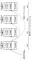
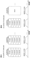
- 3A and 3B are diagrams illustrating an example of a CC-specific TCI state pool and a CC common TCI state pool.
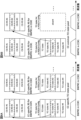
- 4A and 4B are diagrams illustrating an example of TCI states in a CC-specific TCI state pool.
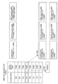
- 5A and 5B are diagrams illustrating an example of TCI states in the CC common TCI state pool.
- 6A and 6B are diagrams illustrating examples of CC-specific RSs in TCI state.
- 7A and 7B are diagrams illustrating examples of CC common RSs in the TCI state.
- FIG. 1 is a diagram illustrating an example of simultaneous beam updating of multiple CCs.
- 2A and 2B are diagrams illustrating an example of a unified/common TCI framework.
- 3A and 3B are diagrams illustrating
- FIG. 8 is a diagram showing an example of the BFR procedure.
- FIG. 9 is a diagram showing an example of instruction method 1-1.
- FIG. 10 is a diagram showing an example of a resource/resource set list according to aspect 1-2.
- 11A to 11C are diagrams showing an example of an enabler according to instruction method 2-1.
- FIG. 12 is a diagram showing an example of a joint TCI state according to instruction method 2-1.
- FIG. 13 is a diagram showing an example of a separate TCI state according to instruction method 2-1.
- FIG. 14 is a diagram showing an example of instruction method 2-2.
- FIG. 15 is a diagram showing an example of instruction method 2-3.
- FIG. 16 is a diagram showing an example of instruction method 2-4.
- FIG. 17 is a diagram showing another example of the instruction method 2-4.
- FIG. 18 is a diagram showing an example of the relationship between the value of the TCI field and the presence/absence of sharing according to instruction method 2-4.
- FIG. 19 is a diagram showing an example of a joint TCI state according to aspect 2-1.
- FIG. 20 is a diagram showing an example of a separate TCI state according to aspect 2-1.
- FIG. 21 is a diagram showing an example of aspect 3-2.
- FIG. 22 is a diagram showing another example of aspect 3-2.
- FIG. 23 is a diagram showing an example of the fourth embodiment.
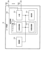
- FIG. 24 is a diagram illustrating an example of a schematic configuration of a wireless communication system according to an embodiment;
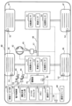
- FIG. 25 is a diagram illustrating an example of the configuration of a base station according to one embodiment.
- FIG. 26 is a diagram illustrating an example of the configuration of a user terminal according to an embodiment
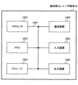
- FIG. 27 is a diagram illustrating an example of hardware configurations of a base station and a user terminal according to an embodiment.
- FIG. 28 is a diagram illustrating an example of a vehicle according to one embodiment;
- the reception processing e.g., reception, demapping, demodulation, decoding
- transmission processing e.g, at least one of transmission, mapping, precoding, modulation, encoding
- the TCI state may represent those that apply to downlink signals/channels.
- the equivalent of TCI conditions applied to uplink signals/channels may be expressed as spatial relations.
- the TCI state is information about the pseudo-colocation (QCL) of signals/channels, and may be called spatial reception parameters, spatial relation information, or the like.
- the TCI state may be set in the UE on a channel-by-channel or signal-by-signal basis.
- QCL is an index that indicates the statistical properties of a signal/channel. For example, when one signal/channel and another signal/channel have a QCL relationship, Doppler shift, Doppler spread, average delay ), delay spread, spatial parameters (e.g., spatial Rx parameter) are identical (QCL with respect to at least one of these). You may
- the spatial reception parameters may correspond to the reception beams of the UE (eg, reception analog beams), and the beams may be specified based on the spatial QCL.
- QCL or at least one element of QCL in the present disclosure may be read as sQCL (spatial QCL).
- QCL types may be defined for the QCL.
- QCL types AD may be provided with different parameters (or parameter sets) that can be assumed to be the same, and the parameters (which may be called QCL parameters) are shown below: QCL type A (QCL-A): Doppler shift, Doppler spread, mean delay and delay spread, QCL type B (QCL-B): Doppler shift and Doppler spread, QCL type C (QCL-C): Doppler shift and mean delay; • QCL Type D (QCL-D): Spatial reception parameters.
- CORESET Control Resource Set
- QCL QCL type D
- a UE may determine at least one of a transmit beam (Tx beam) and a receive beam (Rx beam) for a signal/channel based on the TCI conditions or QCL assumptions of that signal/channel.
- Tx beam transmit beam
- Rx beam receive beam
- the TCI state may be, for example, information about the QCL between the channel of interest (in other words, the reference signal (RS) for the channel) and another signal (for example, another RS). .
- the TCI state may be set (indicated) by higher layer signaling, physical layer signaling or a combination thereof.
- Physical layer signaling may be, for example, downlink control information (DCI).
- DCI downlink control information
- Channels for which TCI states or spatial relationships are set are, for example, Physical Downlink Shared Channel (PDSCH), Physical Downlink Control Channel (PDCCH), Physical Uplink Shared Channel It may be at least one of a channel (PUSCH)) and an uplink control channel (Physical Uplink Control Channel (PUCCH)).
- PDSCH Physical Downlink Shared Channel
- PDCCH Physical Uplink Control Channel
- RSs that have a QCL relationship with the channel are, for example, a synchronization signal block (SSB), a channel state information reference signal (CSI-RS), a measurement reference signal (Sounding It may be at least one of a reference signal (SRS)), a tracking CSI-RS (also called a tracking reference signal (TRS)), and a QCL detection reference signal (also called a QRS).
- SSB synchronization signal block
- CSI-RS channel state information reference signal
- Sounding It may be at least one of a reference signal (SRS)), a tracking CSI-RS (also called a tracking reference signal (TRS)), and a QCL detection reference signal (also called a QRS).
- SRS reference signal
- TRS tracking reference signal
- QRS QCL detection reference signal
- An SSB is a signal block that includes at least one of a Primary Synchronization Signal (PSS), a Secondary Synchronization Signal (SSS), and a Physical Broadcast Channel (PBCH).
- PSS Primary Synchronization Signal
- SSS Secondary Synchronization Signal
- PBCH Physical Broadcast Channel
- An SSB may also be called an SS/PBCH block.
- a QCL type X RS in a TCI state may mean an RS that has a QCL type X relationship with (the DMRS of) a certain channel/signal, and this RS is called a QCL type X QCL source in that TCI state.
- one MAC CE can update the beam index (TCI state) of multiple CCs.
- a UE can be configured by RRC with up to two applicable CC lists (eg, applicable-CC-list). If two applicable CC lists are configured, the two applicable CC lists may correspond to intra-band CA in FR1 and intra-band CA in FR2, respectively.
- the network sends the UE-specific PDSCH TCI States Activation/Deactivation MAC CE for UE-specific PDSCH MAC CE for the serving cell or simultaneous TCI-UpdateList1. ) or the set of serving cells configured in simultaneous TCI-UpdateList2 (simultaneousTCI-UpdateList2). If the indicated serving cell is configured as part of Simultaneous TCI Update List 1 or Simultaneous TCI Update List 2, then its MAC CE is configured within the set of Simultaneous TCI Update List 1 or Simultaneous TCI Update List 2. Applies to all serving cells.
- the network sends the TCI States Indication for UE-specific PDCCH MAC CE of the serving cell or simultaneous TCI-UpdateList1 or simultaneous TCI-UpdateList2.
- (simultaneousTCI-UpdateList2) may indicate the configured TCI state of the set of serving cells configured in (simultaneousTCI-UpdateList2). If the indicated serving cell is configured as part of Simultaneous TCI Update List 1 or Simultaneous TCI Update List 2, then its MAC CE is configured within the set of Simultaneous TCI Update List 1 or Simultaneous TCI Update List 2. Applies to all serving cells.
- PDCCH TCI state activation MAC CE activates the TCI state associated with the same CORESET ID on all BWP/CCs in the applicable CC list.
- PDSCH TCI state activation MAC CE activates TCI state on all BWP/CCs in the applicable CC list.
- A-SRS/SP-SRS spatial relationship activation MAC CE activates the spatial relationship associated with the same SRS resource ID on all BWP/CCs in the applicable CC list.
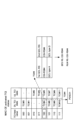
- the UE is configured with an applicable CC list indicating CC #0, #1, #2, #3 and a list indicating 64 TCI states for each CC's CORESET or PDSCH. .
- the corresponding TCI states are activated in CC#1, #2, and #3.
- the UE may base procedure A below.
- the UE issues an activation command to map up to 8 TCI states to codepoints in the DCI field (TCI field) within one CC/DL BWP or within one set of CC/BWPs. receive. If a set of TCI state IDs is activated for a set of CC/DL BWPs, where the applicable list of CCs is determined by the CCs indicated in the activation command, and the same The set applies to all DL BWPs within the indicated CC.
- One set of TCI state IDs can be activated for one set of CC/DL BWPs.
- the UE may base procedure B below.
- the simultaneous TCI update list (simultaneousTCI-UpdateList-r16 and simultaneousTCI-UpdateListSecond-r16)
- the simultaneous TCI cell list (simultaneousTCI- CellList)
- the UE has an index p in all configured DL BWPs of all configured cells in one list determined from the serving cell index provided by the MAC CE command.
- CORESET apply the antenna port quasi co-location (QCL) provided by the TCI state with the same activated TCI state ID value.
- QCL quasi co-location
- a concurrent TCI cell list may be provided for concurrent TCI state activation.
- the UE may base procedure C below.
- spatial relation information for SP or AP-SRS resource set by SRS resource information element (higher layer parameter SRS-Resource) is activated/updated by MAC CE.
- the CC's applicable list is indicated by the simultaneous spatial update list (higher layer parameter simultaneousSpatial-UpdateList-r16 or simultaneousSpatial-UpdateListSecond-r16), and in all BWPs within the indicated CC, the same SRS resource
- the spatial relationship information is applied to the SP or AP-SRS resource with ID.
- a simultaneous TCI cell list (simultaneousTCI-CellList), a simultaneous TCI update list (at least one of simultaneousTCI-UpdateList1-r16 and simultaneousTCI-UpdateList2-r16) are serving cells whose TCI relationships can be updated simultaneously using MAC CE. is a list of simultaneousTCI-UpdateList1-r16 and simultaneousTCI-UpdateList2-r16 do not contain the same serving cell.
- a simultaneous spatial update list (at least one of the upper layer parameters simultaneousSpatial-UpdatedList1-r16 and simultaneousSpatial-UpdatedList2-r16) is a list of serving cells whose spatial relationships can be updated simultaneously using MAC CE.
- simultaneousSpatial-UpdatedList1-r16 and simultaneousSpatial-UpdatedList2-r16 do not contain the same serving cell.
- the simultaneous TCI update list and the simultaneous spatial update list are set by RRC
- the CORESET pool index of the CORESET is set by RRC
- the TCI codepoints mapped to TCI states are indicated by MAC CE.
- CC list, new CC list, simultaneous TCI cell list, simultaneousTCI-CellList, simultaneous TCI update list, simultaneousTCI-UpdateList1-r16, simultaneousTCI-UpdateList2-r16, simultaneous spatial update list, simultaneousSpatial-UpdatedList1-r16, simultaneousSpatial- UpdatedList2-r16, may be read interchangeably.
- simultaneousTCI-UpdateList1, simultaneousTCI-UpdateList1-r16, and simultaneousTCI-UpdateList-r16 may be read interchangeably.
- simultaneousTCI-UpdateList2, simultaneousTCI-UpdateList2-r16, and simultaneousTCI-UpdateListSecond-r16 may be read interchangeably.
- simultaneousSpatial-UpdatedList1, simultaneousSpatial-UpdatedList1-r16, and simultaneousSpatial-UpdateList-r16 may be read interchangeably.
- simultaneousSpatial-UpdatedList2, simultaneousSpatial-UpdatedList2-r16, and simultaneousSpatial-UpdateListSecond-r16 may be read interchangeably.
- the unified TCI framework allows UL and DL channels to be controlled by a common framework.
- the unified TCI framework is Rel. Instead of defining TCI conditions or spatial relationships per channel as in 15, a common beam (common TCI condition) may be indicated and applied to all channels in the UL and DL, or for the UL A common beam may be applied to all channels in the UL and a common beam for the DL may be applied to all channels in the DL.
- One common beam for both DL and UL, or a common beam for DL and a common beam for UL (two common beams in total) are being considered.
- the UE may assume the same TCI state (joint TCI state, joint TCI pool, joint common TCI pool, joint TCI state set) for UL and DL.
- the UE assumes different TCI states for each of UL and DL (separate TCI state, separate TCI pool, UL separate TCI pool and DL separate TCI pool, separate common TCI pool, UL common TCI pool and DL common TCI pool).
- the UL and DL default beams may be aligned by MAC CE-based beam management (MAC CE level beam designation).
- the PDSCH default TCI state may be updated to match the default UL beam (spatial relationship).
- DCI-based beam management may indicate common beam/unified TCI state from the same TCI pool for both UL and DL (joint common TCI pool, joint TCI pool, set).
- X (>1) TCI states may be activated by MAC CE.
- the UL/DL DCI may select 1 out of X active TCI states.
- the selected TCI state may apply to both UL and DL channels/RS.
- the TCI pool (set) may be a plurality of TCI states set by RRC parameters, or a plurality of TCI states activated by MAC CE (active TCI state, active TCI pool, set).
- Each TCI state may be a QCL type A/D RS.
- SSB, CSI-RS, or SRS may be set as QCL type A/D RS.
- the number of TCI states corresponding to each of one or more TRPs may be defined. For example, the number N ( ⁇ 1) of TCI states (UL TCI states) applied to UL channels/RSs and the number M ( ⁇ 1) of TCI states (DL TCI states) applied to DL channels/RSs and may be defined. At least one of N and M may be signaled/configured/indicated to the UE via higher layer signaling/physical layer signaling.
- the UE has X UL and DL common TCI states (corresponding to X TRPs) (joint TCI status) is signaled/set/indicated.
- the UE is notified/configured/instructed of a TCI state common to multiple (two) UL and DL for multiple (two) TRPs (joint TCI state for multiple TRPs).
- multiple (two) UL TCI states and multiple (two) DL TCI states for multiple (two) TRPs State may mean signaled/set/indicated (separate TCI state for multiple TRPs).
- N and M are 1 or 2
- N and M may be 3 or more, and N and M may be different.
- the RRC parameters configure multiple TCI states for both DL and UL.
- the MAC CE may activate multiple TCI states out of multiple configured TCI states.
- a DCI may indicate one of multiple TCI states that have been activated.
- DCI may be UL/DL DCI.
- the indicated TCI conditions may apply to at least one (or all) of the UL/DL channels/RSs.
- One DCI may indicate both UL TCI and DL TCI.
- one point may be one TCI state that applies to both UL and DL, or two TCI states that apply to UL and DL respectively.
- At least one of the multiple TCI states set by the RRC parameters and the multiple TCI states activated by the MAC CE may be called a TCI pool (common TCI pool, joint TCI pool, TCI state pool). good.
- Multiple TCI states activated by a MAC CE may be called an active TCI pool (active common TCI pool).
- RRC parameters higher layer parameters that configure multiple TCI states
- configuration information that configures multiple TCI states, or simply "configuration information.”
- to indicate one of the plurality of TCI states using the DCI may be receiving indication information indicating one of the plurality of TCI states included in the DCI. , it may simply be to receive "instruction information”.
- the RRC parameters configure multiple TCI states (joint common TCI pools) for both DL and UL.
- the MAC CE may activate multiple TCI states (active TCI pool) out of multiple configured TCI states. Separate active TCI pools for each of the UL and DL may be configured/activated.
- a DL DCI or a new DCI format may select (indicate) one or more (eg, one) TCI states.
- the selected TCI state may be applied to one or more (or all) DL channels/RS.
- the DL channel may be PDCCH/PDSCH/CSI-RS.
- the UE uses Rel.
- a 16 TCI state operation (TCI framework) may be used to determine the TCI state for each channel/RS in the DL.
- a UL DCI or new DCI format may select (indicate) one or more (eg, one) TCI states.
- the selected TCI state may be applied to one or more (or all) UL channels/RS.
- the UL channel may be PUSCH/SRS/PUCCH.
- different DCIs may indicate UL TCI and DL DCI separately.
- the beam directing DCI for unified/common TCI state may be DCI format 1_1/1_2 with DL assignment (scheduling).
- the beam directing DCI for the unified/common TCI state may be DCI format 1_1/1_2 without DL assignment (scheduling) or may be a new DCI format. This is useful when there is no DL data but beam pointing to unified/common TCI state.
- the RRC-configured TCI status pool is defined in Rel. 15/16 may be configured in the PDSCH configuration (PDSCH-Config) for each BWP/CC. Such RRC-configured TCI state pool configuration does not imply that separate DL/ULTCI state pools are excluded or supported.
- the RRC-configured TCI state pool may not be in the PDSCH configuration (PDSCH-Config) for each BWP/CC and may be replaced by a reference to the RRC-configured TCI state pool in the reference BWP/CC. .
- the RRC-configured TCI state pool is configured.
- the UE applies the RRC-configured TCI state pool in that reference BWP/CC.
- a UE capability is introduced to report the maximum number of TCI state pools to support across multiple BWPs and multiple CCs in a band, the candidate value of which includes at least one.
- the source RS determined from the common TCI state ID indicated to provide the QCL type D indication and determine the UL TX spatial filter may be configured in the target CC or another CC.
- configurations 1 to 2 below may be supported without additional QCL rules.
- Configuration 1 A single source RS across multiple CCs determined from the indicated common TCI state ID to provide QCL type D indication and determine the UL TX spatial filter for a set of configured CCs may be [[Configuration 2]] One source RS per CC is determined from the indicated common TCI state ID to provide QCL type D indication and determine the UL TX spatial filter for the set of configured CCs. may Multiple CC-specific source RSs may be associated with the same QCL type D RS.
- the configured CC/BWP set includes all BWPs in the configured CC.
- CC-specific TCI state pool/configuration (case 1) and CC-common TCI state pool/configuration (case 2) may be supported.
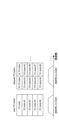
- FIG. 3A shows an example of a CC-specific TCI state pool.
- the TCI status list in PDSCH configuration is configured for BWP1 in CC1
- the TCI status list in PDSCH configuration is configured for BWP1 in CC2.
- One MAC CE/DCI indicates the TCI state ID.
- FIG. 3B shows an example of a CC common TCI state pool.
- the TCI status list in PDSCH configuration is configured for BWP1 in CC1
- the TCI status list in PDSCH configuration is absent for BWP1 in CC2.
- One MAC CE/DCI indicates a TCI state ID (eg, TCI state #2).
- TCI state information element (TCI-State) in the TCI state pool contains TCI state ID, QCL type 1 (QCL-Info), and QCL type 2 (QCL-Info, QCL-Info). may contain.
- FIG. 4A shows an example where the TCI state in the CC-specific TCI state pool indicates a CC-specific QCL type D RS.
- FIG. 4B shows an example where the TCI state in the CC-specific TCI state pool indicates CC common QCL type D RS.
- FIG. 5A shows an example where the TCI state in the CC common TCI state pool indicates a CC-specific QCL type D RS.
- FIG. 5B shows an example where the TCI state in the CC common TCI state pool indicates CC common QCL type D RS.
- the TCI state may indicate CC-specific (BWP/CC-specific) RSs (eg, QCL type A RSs) on each BWP/CC.
- CC-specific (BWP/CC-specific) RSs eg, QCL type A RSs
- FIG. 6A shows an example where the TCI state in the CC-specific TCI state pool indicates the CC-specific RS.
- the TCI state set for BWP1 in CC1 indicates the CC-specific RS for BWP1 in CC1.
- the TCI state set for BWP1 in CC2 indicates the CC-specific RS for BWP1 in CC2.
- FIG. 6B shows an example where the TCI state in the CC common TCI state pool indicates CC-specific RSs.
- the TCI state set for BWP1 in CC1 indicates the CC-specific RS for BWP1 in CC1 and the CC-specific RS for BWP1 in CC2 (with the same RS ID).
- the TCI state set for BWP1 in CC1 may not contain the BWP/CC ID.
- the TCI state may indicate a CC-common (BWP/CC-common) RS on each BWP/CC (eg, QCL type D RS of CSI-RS with repetition).
- BWP/CC-common CC-common
- FIG. 7A shows an example where the TCI state in the CC-specific TCI state pool indicates CC-common RS.
- the TCI state set for BWP1 in CC1 indicates the CC common RS for BWP1 in CC1
- the TCI state set for BWP1 in CC2 indicates the (same) CC common RS for BWP1 in CC2.
- FIG. 7B shows an example where the TCI state in the CC common TCI state pool indicates the CC common RS.
- the TCI state set for BWP1 in CC1 indicates the CC common RS for all CCs/BWPs.
- the TCI state may include QCL type A RS/QCL type D RS, QCL type A RS for frequency range (FR) 1, QCL type A RS for FR2 /QCL type D RS may be included.
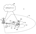
- multi-TRP PDSCH In NR, one or more transmission/reception points (Transmission/Reception Points (TRP)) (multi TRP (multi TRP (MTRP))) uses one or more panels (multi-panel) to the UE DL transmission is under consideration. It is also being considered that the UE uses one or more panels to perform UL transmissions for one or more TRPs.
- TRP Transmission/Reception Points
- MTRP multi TRP
- a plurality of TRPs may correspond to the same cell identifier (cell identifier (ID)) or may correspond to different cell IDs.
- the cell ID may be a physical cell ID or a virtual cell ID.
- Multi-TRPs may be connected by ideal/non-ideal backhauls to exchange information, data, and the like.
- Different codewords (CW) and different layers may be transmitted from each TRP of the multi-TRP.
- Non-Coherent Joint Transmission NCJT may be used as one form of multi-TRP transmission.
- TRP#1 modulate-maps a first codeword and layer-maps a first number of layers (e.g., two layers) with a first precoding to transmit a first PDSCH.
- TRP#2 also modulates and layer-maps a second codeword to transmit a second PDSCH with a second number of layers (eg, 2 layers) with a second precoding.
- multiple PDSCHs to be NCJTed may be defined as partially or completely overlapping in at least one of the time and frequency domains. That is, the first PDSCH from the first TRP and the second PDSCH from the second TRP may overlap at least one of time and frequency resources.
- first PDSCH and second PDSCH are not quasi-co-located (QCL).
- Reception of multiple PDSCHs may be translated as simultaneous reception of PDSCHs that are not of a certain QCL type (eg, QCL type D).
- Multiple PDSCHs from multiple TRPs may be scheduled using one DCI (single DCI, single PDCCH) (single master mode, based on single DCI Multi-TRP (single-DCI based multi-TRP)).
- Multiple PDSCHs from multi-TRP may be scheduled using multiple DCIs (multi-DCI, multiple PDCCH) (multi-master mode, multi-DCI based multi-TRP (multiple PDCCH)). TRP)).
- the RVs may be the same or different for the multi-TRPs.
- multiple PDSCHs from multiple TRPs are time division multiplexed (TDM).
- TDM time division multiplexed
- multiple PDSCHs from multiple TRPs are transmitted within one slot.
- multiple PDSCHs from multiple TRPs are transmitted in different slots.
- one control resource set (CORESET) in PDCCH configuration information (PDCCH-Config) may correspond to one TRP.
- the UE may determine multi-TRP based on single DCI if the following conditions are met: In this case, two TRPs may be translated into two TCI states indicated by MAC CE/DCI. [conditions] "Enhanced TCI States Activation/Deactivation for UE- specific PDSCH MAC CE)” is used.
- DCI for common beam indication may be a UE-specific DCI format (e.g., DL DCI format (e.g., 1_1, 1_2), UL DCI format (e.g., 0_1, 0_2)), or a UE group common (UE-group common) DCI format.
- DL DCI format e.g., 1_1, 1_2
- UL DCI format e.g., 0_1, 0_2
- UE group common UE-group common
- the common TCI state indicated to the UE is expected to be common between CCs (cells) (at least QCL type D between CCs). This conforms to existing specifications (Rel. 15/16) is not supported.
- updating/activating a common TCI state ID is being considered to provide common QCL information/common UL transmit spatial filters across a set of configured CCs.
- a single TCI state pool configured by RRC for a set of multiple CCs (cells)/BWPs configured may be shared (configured). For example, a cell group TCI state may be defined, or a TCI state pool for the PDSCH in the reference cell may be reused. There is no CC (cell) ID for the QCL type A RS in the TCI state, and the CC (cell) ID for the QCL type A RS may be determined according to the target CC (cell) of the TCI state.
- a common TCI state pool is set for each of multiple CC/BWPs, so if one common TCI state is indicated by MAC CE/DCI, the indicated common TCI state is (all CC/BWPs included in a preset CC/BWP list).
- a TCI state pool may be configured by RRC for each individual CC.
- a common TCI state pool is set up (shared) for multiple CCs by RRC, the TCI states in the common TCI state pool are indicated by a common TCI state ID, and one determined based on the TCI state.
- the RS will be used to indicate QCL type D across multiple CC/sets configured (Constraint 1).
- a separate common TCI state pool is configured per CC by RRC, the TCI state in the common state pool is indicated by the common TCI state ID, and one RS determined based on that TCI state is configured will be used to denote QCL type D over a set of multiple CCs/sets (Constraint 2).
- the first slot to apply the indicated TCI is at least Y symbols after the last symbol of the acknowledgment (ACK) for joint or separate DL/UL beam indication. It is considered that the first slot to apply the indicated TCI is at least Y symbols after the last symbol of the ACK/negative acknowledgment (NACK) for joint or separate DL/UL beam indications.
- the Y symbol may be set by the base station based on UE capabilities. The UE capabilities may be reported on a symbol-by-symbol basis.
- the application time of the beam pointing may follow any of options 1 to 3 below.
- [Option 1] Both the first slot and the Y symbol are determined on the carrier with the lowest SCS among the one or more carriers to which the beam pointing applies.
- [Option 2] Both the first slot and the Y symbol are determined on the carrier with the lowest SCS among the one or more carriers applying the beam pointing and the UL carrier carrying the ACK.
- Radio Link Monitoring In NR, Radio Link Monitoring (RLM) is utilized.
- the base station may set a radio link monitoring reference signal (Radio Link Monitoring RS (RLM-RS)) for each BWP to the UE using higher layer signaling.
- RLM-RS Radio Link Monitoring RS
- the UE may receive configuration information for RLM (eg, RRC "RadioLinkMonitoringConfig" information element).
- the configuration information for the RLM may include failure detection resource configuration information (for example, "failureDetectionResourcesToAddModList” of the upper layer parameter).
- the failure detection resource configuration information may include parameters related to RLM-RS (for example, "RadioLinkMonitoringRS" of higher layer parameters).
- the UE may identify the RLM-RS resource based on the index corresponding to the RLM-RS resource and perform RLM using the RLM-RS resource.
- the UE follows the implicit RLM-RS decision (implicit RS decision) procedure as follows.
- the UE uses that RS provided for the active TCI state for PDCCH reception in RLM.
- the active TCI state for PDCCH reception includes two RSs, the UE assumes one RS has QCL type D, and the UE uses that RS with QCL type D for RLM. The UE does not assume that both RSs have QCL type D.
- the UE is not required to use aperiodic or semi-persistent RSs for RLM.
- L max 4
- the UE is provided N Select RLM RSs. If more than one CORESET is associated with multiple search space sets with the same monitoring period, the UE determines the order of CORESETs from the highest CORESET index.
- L max is the maximum number of SS/PBCH block indices in the cell.
- the maximum number of SS/PBCH blocks transmitted in a half-frame is L max .
- BFD Beam Failure Detection
- BFR Beam Failure Recovery
- the UE and the base station e.g., gNB (gNodeB)
- the beam used for signal transmission transmission beam, Tx beam, etc.
- the beam used for signal reception reception beam, Rx beam, etc.
- Radio link failure may occur frequently due to deterioration of radio link quality. Since the occurrence of RLF requires cell reconnection, frequent occurrence of RLF causes degradation of system throughput.
- BFR beam recovery
- BFR beam failure recovery
- L1/L2 Layer 1/Layer 2
- a beam failure (BF) in the present disclosure may also be called a link failure.
- FIG. 8 shows Rel. 15 A diagram showing an example of a beam recovery procedure in NR.
- the number of beams, etc. is an example, and is not limited to this.
- the UE performs measurements based on reference signal (RS) resources transmitted using two beams.
- RS reference signal
- the RS may be at least one of a synchronization signal block (SSB) and a channel state measurement RS (Channel State Information RS (CSI-RS)).
- SSB may also be called an SS/PBCH (Physical Broadcast Channel) block.
- PBCH Physical Broadcast Channel
- RS is a primary synchronization signal (Primary SS (PSS)), a secondary synchronization signal (Secondary SS (SSS)), a mobility reference signal (Mobility RS (MRS)), a signal included in SSB, SSB, CSI-RS, for demodulation At least one of a reference signal (DeModulation Reference Signal (DMRS)), a beam-specific signal, etc., or a signal configured by extending or modifying these may be used.
- the RS measured in step S101 is an RS for beam failure detection (Beam Failure Detection RS (BFD-RS), an RS for beam failure detection), an RS (BFR-RS) for use in a beam recovery procedure, or the like.
- BFD-RS Beam Failure Detection RS
- BFR-RS RS for use in a beam recovery procedure, or the like.
- step S102 the UE cannot detect the BFD-RS (or the reception quality of the RS deteriorates) due to the radio waves from the base station being jammed.
- Such disturbances can be caused, for example, by effects such as obstacles, fading, and interference between the UE and the base station.
- the UE detects a beam failure when a predetermined condition is met.
- the UE may detect the occurrence of a beam failure, for example, when BLER (Block Error Rate) is less than a threshold for all configured BFD-RSs (BFD-RS resource configuration).
- BLER Block Error Rate
- BFD-RS resource configuration a threshold for all configured BFD-RSs
- the lower layer (physical (PHY) layer) of the UE may notify (indicate) the beam failure instance to the upper layer (MAC layer).
- the criteria for determination are not limited to BLER, and may be the reference signal received power (Layer 1 Reference Signal Received Power (L1-RSRP)) in the physical layer.
- L1-RSRP Layer 1 Reference Signal Received Power
- beam failure detection may be performed based on a physical downlink control channel (PDCCH) or the like.
- BFD-RS may be expected to be Quasi-Co-Location (QCL) with the DMRS of the PDCCH monitored by the UE.
- QCL is an index that indicates the statistical properties of a channel. For example, if one signal/channel and another signal/channel have a QCL relationship, between these different signals/channels, Doppler shift, Doppler spread, average delay ), delay spread, spatial parameter (e.g., spatial Rx Parameter) are the same (QCL with respect to at least one of these). You may
- the spatial reception parameters may correspond to the reception beams of the UE (eg, reception analog beams), and the beams may be specified based on the spatial QCL.
- QCL or at least one element of QCL in the present disclosure may be read as sQCL (spatial QCL).
- Information on BFD-RS eg, RS index, resource, number, number of ports, precoding, etc.
- BFD beam failure detection
- Information on BFD-RS may be set (notified) to Information about BFD-RS may be called information about BFR resources.
- a higher layer (eg, MAC layer) of the UE may start a predetermined timer (which may be referred to as a beam failure detection timer) when receiving a beam failure instance notification from the PHY layer of the UE.
- a predetermined timer which may be referred to as a beam failure detection timer
- the MAC layer of the UE receives beam failure instance notifications a certain number of times (for example, beamFailureInstanceMaxCount set by RRC) or more before the timer expires, it triggers BFR (for example, starts one of the random access procedures described later ).
- the base station may determine that the UE has detected a beam failure when there is no notification from the UE or when a predetermined signal (beam recovery request in step S104) is received from the UE.
- step S103 the UE starts searching for new candidate beams (candidate beam detection (CBD)) to be newly used for communication for beam recovery.
- CBD candidate beam detection
- the UE may select a new candidate beam corresponding to that RS.
- RSs measured in step S103 are new candidate RS, RS for new candidate beam identification, NCBI-RS (New Candidate Beam Identification RS), RS for new beam identification, RS for new beam identification, NBI-RS (New Beam Identification RS), CBI-RS (Candidate Beam Identification RS), CB-RS (Candidate Beam RS), Candidate Beam Detection RS (CBD-RS), etc.
- NBI-RS may be the same as or different from BFD-RS. Note that the new candidate beam may be simply called a candidate beam or a candidate RS.
- a UE may determine a beam corresponding to an RS that satisfies a predetermined condition as a new candidate beam (new beam, q_new).
- the UE may determine new candidate beams based on, for example, the configured NBI-RSs whose L1-RSRP exceeds the threshold. Note that the criteria for judgment are not limited to L1-RSRP.
- L1-RSRP for SSB may be referred to as SS-RSRP.
- L1-RSRP for CSI-RS may be referred to as CSI-RSRP.
- NBI-RS e.g. resources, number of RSs, number of ports, precoding, etc.
- NBI new beam identification
- Information about new candidate RSs may be obtained based on information about BFD-RSs.
- Information about NBI-RS may be called information about resources for NBI or the like.
- BFD-RS may be interchanged with radio link monitoring reference signals (Radio Link Monitoring RS (RLM-RS)).
- RLM-RS Radio Link Monitoring RS
- step S104 the UE that has identified the new candidate beam transmits a beam failure recovery request (BFRQ).
- a beam recovery request may also be referred to as a beam recovery request signal, a beam failure recovery request signal, or the like.
- BFRQ for example, physical uplink control channel (PUCCH), random access channel (PRACH), physical uplink shared channel (PUSCH), configured (setting) It may be transmitted using at least one of a configured grant (CG) PUSCH.
- PUCCH physical uplink control channel
- PRACH random access channel
- PUSCH physical uplink shared channel
- CG configured grant
- the BFRQ may include information on the new candidate beam/new candidate RS identified in step S103.
- Resources for BFRQ may be associated with the new candidate beam.
- Beam information includes beam index (BI), port index of predetermined reference signal, RS index, resource index (for example, CSI-RS resource indicator (CRI)), SSB resource index (SSBRI)) or the like.
- CB-BFR Contention-Based BFR
- CF-BFR Contention-Free BFR
- a UE may transmit a preamble (also called an RA preamble, a Physical Random Access Channel (PRACH), a RACH preamble, etc.) as a BFRQ using PRACH resources.
- a preamble also called an RA preamble, a Physical Random Access Channel (PRACH), a RACH preamble, etc.
- the UE may transmit a randomly selected preamble from one or more preambles.
- the UE may transmit a UE-specific assigned preamble from the base station.
- the base station may assign the same preamble to multiple UEs.
- the base station may assign preambles for individual UEs.
- CB-BFR and CF-BFR are respectively referred to as CB PRACH-based BFR (contention-based PRACH-based BFR (CBRA-BFR)) and CF PRACH-based BFR (contention-free PRACH-based BFR (CFRA-BFR)).
- CBRA-BFR may be referred to as CBRA for BFR
- CFRA-BFR may be referred to as CFRA for BFR.
- information on PRACH resources may be notified by higher layer signaling (RRC signaling, etc.), for example.
- RRC signaling may include information indicating the correspondence between detected DL-RSs (beams) and PRACH resources, and different PRACH resources may be associated with each DL-RS.
- the base station that detected the BFRQ transmits a response signal (which may be called a gNB response or the like) to the BFRQ from the UE.
- the response signal may include reconfiguration information (eg, DL-RS resource configuration information) for one or more beams.
- the response signal may be transmitted, for example, in the UE common search space of PDCCH.
- the response signal is reported using a cyclic redundancy check (CRC) scrambled PDCCH (DCI) by the UE identifier (eg, cell-radio RNTI (Cell-Radio RNTI (C-RNTI))) may be The UE may determine which transmit beam and/or receive beam to use based on the beam reconstruction information.
- CRC cyclic redundancy check
- DCI cell-radio RNTI
- C-RNTI Cell-Radio RNTI
- the UE may monitor the response signal based on at least one of the BFR control resource set (CControl Resource SET (CORESET)) and the BFR search space set.
- CControl Resource SET CORESET
- contention resolution may be determined to be successful when the UE receives the PDCCH corresponding to the C-RNTI for itself.
- a period may be set for the UE to monitor the response from the base station (eg, gNB) to BFRQ.
- the time period may be referred to, for example, as a gNB response window, a gNB window, a beam recovery request response window, and the like.
- the UE may retransmit the BFRQ if no gNB response is detected within the window period.
- the UE may send a message to the base station indicating that the beam reconstruction is complete.
- the message may be transmitted by PUCCH or PUSCH, for example.
- Beam recovery success may represent, for example, the case of reaching step S106.
- a beam recovery failure may correspond, for example, to reaching a predetermined number of BFRQ transmissions or to expiring a beam failure recovery timer (Beam-failure-recovery-Timer).
- Rel. 15 supports beam recovery procedures (eg, BFRQ notification) for beam failures detected in SpCells (PCell/PSCell) using random access procedures.
- the beam recovery procedure for the beam failure detected in the SCell eg, notification of BFRQ
- PUCCH for BFR eg, scheduling request (SR)
- MAC CE for BFR eg, UL-SCH
- the UE may transmit information about beam failures using MAC CE-based two-step.
- the information about beam failure may include information about the cell that detected the beam failure and information about the new candidate beam (or new candidate RS index).
- Step 1 When BF is detected, the UE may transmit a PUCCH-BFR (scheduling request (SR)) to the PCell/PSCell. A UL grant (DCI) for step 2 below may then be sent from the PCell/PSCell to the UE.
- PUCCH-BFR scheduling request
- DCI UL grant
- Step 2 The UE then sends information about the cell in which the beam failure was detected (failed) (e.g., cell index) and information about the new candidate beam using MAC CE via an uplink channel (e.g., PUSCH) to You may transmit to a base station (PCell/PSCell).
- a base station PCell/PSCell
- the QCL of PDCCH/PUCCH/PDSCH/PUSCH may be updated to a new beam.
- step numbers are merely numbers for explanation, and multiple steps may be grouped together or their order may be changed. Also, whether or not to implement BFR may be configured in the UE using higher layer signaling.
- BFD-RS/NBI-RS BFD-RS/NBI-RS
- the UE may be configured with explicit BFD-RS (eg, SSB/CSI-RS), such as by higher layer signaling.
- the UE may be configured with an implicit BFD-RS based on the TCI state of PDCCH/CORESET in BFD (the UE may determine the BFD-RS based on the TCI state).
- the UE may be configured with explicit NBI-RS (eg, SSB/CSI-RS) by higher layer signaling or the like.
- the explicit BFD-RS, the implicit BFD-RS, the explicit NBI-RS, etc. will be specifically described below.
- the UE periodically (P)-CSI-RS resource configuration index by failureDetectionResourcesToAddModList for radio link quality measurements on that BWP of that serving cell.
- a set of q 0 bars can be provided.
- the UE shall create a candidate beam RS list (candidateBeamRSList) or an extended candidate beam RS list (candidateBeamRSListExt) or a candidate beam RS list for SCell for radio link quality measurement on that BWP of the serving cell.
- At least one set q 1 of P-CSI-RS resource configuration index and SS/PBCH block index can be provided by (candidateBeamRSSCellList).
- the q 0 bar is the notation with "q 0 " overlined. Below, the q0 bar is simply denoted as q0 .
- the q 1 bar is the notation with "q 1 " overlined. Below, the q 1 bar is simply denoted as q 1 .
- the set q 0 of P-CSI-RS resources provided by failure detection resources may be referred to as explicit BFD-RS.
- Set q 1 may be called Explicit New Beam Identification (NBI)-RS.
- the UE can be explicitly configured with BFD-RS set q 0 for per-cell BFR.
- the UE may perform L1-RSRP measurements, etc., using RS resources corresponding to indices in at least one of set q 0 and set q 1 to detect beam failure.
- providing the above-described upper layer parameter indicating the information of the index corresponding to the BFD resource can be interpreted as setting the BFD resource, setting the BFD-RS, etc.
- BFD resources, periodic CSI-RS resource configuration index or SSB index set q 0 , and BFD-RS may be read interchangeably.
- the UE If the UE is not provided with q 0 by failureDetectionResources for one BWP of its serving cell, indicated by the TCI-State for the corresponding CORESET that the UE uses for PDCCH monitoring. It decides to include in set q 0 a P-CSI-RS resource configuration index that has the same value as the RS index in the RS set. If there are two RS indices in one TCI state, set q 0 contains RS indices with QCL type D configuration for the corresponding TCI state. The UE assumes that set q 0 contains up to two RS indices. The UE assumes a single-port RS within its set q 0 .
- This set q 0 may be called implicit BFD-RS.
- the physical layer in the UE assesses the radio link quality according to resource configuration set q 0 against a threshold Q out,LR .
- the UE may quasi co-locate the SS/PBCH block on the PCell or PSCell with the DM-RS of the PDCCH reception monitored by the UE, or the PDCCH reception monitored by the UE.
- the radio link quality is evaluated only according to the DM-RS and the pseudo-colocated P-CSI-RS resource configuration.
- the UE evaluates the radio link quality according to the PDCCH/CORESET DMRS and QCLed BFD-RS.
- BFR per cell per-cell BFR
- BFR per TRP per-TRP BFR
- New RRC configuration parameters (eg, TRP-ID, group-ID, new-ID, etc.) are being considered to be configured for single DCI-based multi-TRP.
- the new RRC configuration parameters may follow either of Options 1 and 2 below.
- Each CORESET is associated with a new ID. If two sets of BFD-RS for per-TRP BFR are configured by higher layers, the BFD-RS in one set and the CORESET to be QCLed are associated with the same new ID and the BFD-RS in different sets. A CORESET QCLed with may be associated with a different new ID.
- Each TCI state is associated with a new ID.
- the BFD-RS in one set and the TCI state/CORESET to be QCLed are associated with the same new ID and in different sets.
- the TCI state/CORESET QCLed with the BFD-RS may be associated with different new IDs.
- SFN PDCCH Scheme 1 is being considered to include HST and URLLLC.
- SFN PDCCH scheme 1 SFN PDCCH scheme 1, SFN PDCCH scheme, SFN PDCCH, and TRP-based pre-compensation scheme may be read interchangeably.
- the SFN PDCCH scheme may include both 1 and 2 TCI states. If the SFN PDCCH scheme is configured and two TCI states are activated for at least one CORESET, for the implicit configuration of the RS for BFD, the RS of the CORESET with one and two TCI states is being considered for use.
- Transmission power control ⁇ PUSCH transmission power control>
- the transmission power of PUSCH is controlled based on the TPC command (also called value, increment/decrement value, correction value, etc.) indicated by the value of a field in DCI (also called TPC command field, etc.).
- a UE may use a parameter set (open-loop parameter set) with index j, index l in a power control adjustment state (PUSCH power control adjustment state) to activate an active UL on carrier f of serving cell c.
- PUSCH transmission power P PUSCH, b, f, c (i, j, q d , l)
- i [dBm] is P CMAX,f,c(i) , PO_PUSCH,b,f,c (j), M PUSCH RB,b,f,c (i), ⁇ b,f,c (j)
- It may be based on at least one of PL b,f,c (q d ), ⁇ TF,b,f,c (i), f b,f,c (i,l).
- the power control adjustment state may also be called a closed loop (CL)-power control (PC) state, a value based on the TPC command of the power control adjustment state index l, an accumulated value of the TPC commands, or a closed loop value.
- l may be called the closed-loop index.
- the PUSCH transmission opportunity i is a period during which the PUSCH is transmitted, and may be composed of, for example, one or more symbols, one or more slots, or the like.
- P CMAX,f,c(i) is, for example, the user terminal transmission power (also referred to as maximum transmission power, UE maximum output power, etc.) configured for carrier f of serving cell c at transmission opportunity i.
- P O_PUSCH,b,f,c (j) is, for example, a parameter related to the target received power set for active UL BWP b of carrier f of serving cell c at transmission opportunity i (eg, a parameter related to transmit power offset, transmission (Also referred to as power offset P0, target received power parameter, etc.).
- PO_UE_PUSCH,b,f,c (j) may be the sum of PO_NOMINAL_PUSCH,f,c (j) and PO_UE_PUSCH,b,f,c (j).
- M PUSCH RB,b,f,c (i) is, for example, the number of resource blocks (bandwidth) allocated to PUSCH for transmission opportunity i in active UL BWP b of serving cell c and carrier f with subcarrier spacing ⁇ .
- ⁇ b,f,c (j) are values provided by higher layer parameters (eg, msg3-Alpha, p0-PUSCH-Alpha, also called fractional factors, etc.).
- PL b, f, c (q d ) is, for example, a reference signal (RS) for downlink BWP associated with active UL BWP b of carrier f of serving cell c, pathloss reference RS, pathloss (PL)-RS , pathloss reference RS, pathloss measurement DL-RS, PUSCH-PathlossReferenceRS) is the pathloss (pathloss estimation [dB], pathloss compensation) calculated by the user terminal using the index qd .
- RS reference signal
- the UE uses a synchronization signal (SS) to obtain the Master Information Block (MIB).
- SS synchronization signal
- MIB Master Information Block
- PL b,f,c (q d ) may be calculated using the RS resources from the /physical broadcast channel (PBCH) block (SS block (SSB)).
- the set of RS resource indices may include one or both of a set of SS/PBCH block indices and a set of channel state information (CSI)-reference signal (RS) resource indices.
- the UE may identify the RS resource index q d within the set of RS resource indices.
- the UE may use the same RS resource index q d for the corresponding PRACH transmission.
- RAR Random Access Response
- a UE is provided with a PUSCH power control setting (e.g., SRI-PUSCH-PowerControl) by a sounding reference signal (SRS) resource indicator (SRI) and is provided with one or more values of pathloss reference RS IDs.
- SRS sounding reference signal
- SRI resource indicator
- the mapping between the set of values for the SRI field in DCI format 0_1 and the set of ID values of pathloss reference RSs is defined in higher layer signaling (e.g., sri-PUSCH in SRI-PUSCH-PowerControl -PowerControl-Id).
- the UE may determine the RS resource index qd from the ID of the pathloss reference RS mapped to the SRI field value in the DCI format 0_1 that schedules the PUSCH.
- the UE will The same RS resource index q d may be used for PUCCH transmissions in resources.
- the UE may use the RS resource index q d with a pathloss reference RS ID of zero.
- a configured grant configuration e.g. ConfiguredGrantConfig
- the RS resource index is determined by the pathloss reference index (e.g. pathlossReferenceIndex) in the specific parameter.
- q d may be provided to the UE.
- the UE For PUSCH transmission configured by the configuration grant configuration, if the configuration grant configuration does not contain a specific parameter, the UE selects the RS from the ID value of the pathloss reference RS mapped to the SRI field in the DCI format that activates the PUSCH transmission. A resource index qd may be determined. If the DCI format does not include the SRI field, the UE may determine the RS resource index q d with a pathloss reference RS ID of zero.
- ⁇ TF,b,f,c (i) is the transmission power adjustment component (offset, transmission format compensation) for UL BWP b of carrier f in serving cell c.
- f b,f,c (i,l) is the PUSCH power control adjustment state for active UL BWP b of carrier f in serving cell c at transmission opportunity i.
- f b,f,c (i,l) may be based on ⁇ PUSCH,b,f,c (i,l).
- f b,f,c (i,l) may be based on the accumulated values of ⁇ PUSCH,b,f,c (m,l).
- f b,f,c (i,l) may be ⁇ PUSCH,b,f,c (i,l) (absolute value).
- the UE sets the TPC command value to Accumulate and determine transmit power (apply TPC command value via accumulation) based on accumulation result (power control state).
- TPC-Accumulation When information indicating invalidity of TPC accumulation (TPC-Accumulation) is set (when information indicating invalidation of TPC accumulation is provided, when TPC accumulation is set to be invalid), the UE uses the TPC command Determine transmit power based on TPC command value (power control state) without accumulating values (apply TPC command value without accumulation).
- ⁇ PUSCH,b,f,c (i,l) is a TPC command value included in DCI format 0_0 or DCI format 0_1 that schedules PUSCH transmission opportunity i on active UL BWP b of carrier f of serving cell c, or a specific TPC command value encoded in conjunction with other TPC commands in DCI format 2_2 with CRC scrambled by a Radio Network Temporary Identifier (RNTI) (e.g., TPC-PUSCH-RNTI) of .
- RNTI Radio Network Temporary Identifier
- K PUSCH (i) is the serving cell after the last symbol of the corresponding PDCCH reception and before the first symbol of that PUSCH transmission.
- c may be the number of symbols in active UL BWP b for carrier f.
- K PUSCH (i) is the number of symbols per slot N symb slot in active UL BWP b of carrier f in serving cell c and PUSCH common configuration information It may be the number of K PUSCH,min symbols equal to the product of the minimum of the values provided by k2 in (PUSCH-ConfigCommon).
- the power control adjustment state may be set to have a plurality of states (for example, two states) or a single state depending on upper layer parameters. Also, if multiple power control adjustment states are configured, an index l (eg, l ⁇ 0,1 ⁇ ) may identify one of the multiple power control adjustment states.
- the transmission power of PUCCH is the TPC command (value, increment/decrement value, correction value, instruction value, etc.) indicated by the value of the field in DCI (also called TPC command field, first field, etc.). is controlled based on
- the PUCCH transmission opportunity for the active UL BWP b of the carrier f of the serving cell c (also known as the transmission period, etc.
- the transmission power of PUCCH at i) (P PUCCH, b, f, c (i, qu , qd , l)) [dBm] is P CMAX, f, c (i), PO_PUCCH, b, f , c (q u ), M PUCCH RB, b, f, c (i), PL b, f, c (q d ), ⁇ F_PUCCH (F), ⁇ TF, b, f, c (i), g may be based on at least one of b, f, c (i, l).
- the PUCCH transmission opportunity i is a period during which the PUCCH is transmitted, and may be composed of, for example, one or more symbols, one or more slots, or the like.
- P CMAX,f,c (i) is, for example, the user terminal transmission power (also referred to as maximum transmission power, UE maximum output power, etc.) configured for carrier f of serving cell c at transmission opportunity i.
- P O_PUCCH,b,f,c (q u ) is, for example, a parameter related to the target received power set for active UL BWP b of carrier f of serving cell c at transmission opportunity i (eg, a parameter related to transmit power offset, (also referred to as a transmission power offset P0 or a target reception power parameter, etc.).
- M PUCCH RB,b,f,c (i) is, for example, the number of resource blocks (bandwidth) allocated to PUCCH for transmission opportunity i in active UL BWP b of serving cell c and carrier f with subcarrier spacing ⁇ .
- PL b,f,c (q d ) is, for example, a reference signal for downlink BWP associated with active UL BWP b of carrier f of serving cell c (pathloss reference RS, pathloss(PL)-RS, pathloss reference RS, pathloss (pathloss estimation [dB], pathloss compensation) calculated by the user terminal using the index qd of pathloss measurement DL-RS, PUCCH-PathlossReferenceRS).
- the UE uses RS resources obtained from the SS/PBCH block used to obtain the MIB. to calculate the pathloss PL b,f,c (q d ).
- pathlossReferenceRSs in PUCCH power control information (PUCCH-PowerControl)
- PUCCH spatial relationship information (PUCCH-SpatialRelationInfo)
- the UE is provided with pathloss reference RS information for PUCCH
- This reference signal resource is either on the same serving cell or on the serving cell indicated by the value of pathlossReferenceLinking, if given.
- the pathloss reference association information indicates which DL the UE applies as a pathloss reference, a special cell (SpCell) or a secondary cell (SCell) corresponding to this UL.
- a SpCell may be a primary cell (PCell) in a master cell group (MCG) or a primary secondary cell (PSCell) in a secondary cell group (SCG).
- Pathloss reference RS information indicates a set of reference signals (eg, CSI-RS configuration or SS/PBCH block) used for PUCCH pathloss estimation.
- ⁇ F_PUCCH (F) is an upper layer parameter given for each PUCCH format.
- ⁇ TF,b,f,c (i) is the transmission power adjustment component (offset) for UL BWP b for carrier f in serving cell c.
- g b,f,c (i,l) is the value based on the TPC command of the power control adjustment state index l of the active UL BWP of carrier f for serving cell c and transmission opportunity i (e.g., power control adjustment state, TPC command accumulated value, closed-loop value, PUCCH power adjustment state).
- transmission opportunity i e.g., power control adjustment state, TPC command accumulated value, closed-loop value, PUCCH power adjustment state.
- g b,f,c (i,l) may be based on ⁇ PUCCH,b,f,c (i,l).
- g b,f,c (i,l) may be based on the accumulated value of ⁇ PUCCH,b,f,c (i,l).
- g b,f,c (i,l) may be ⁇ PUCCH,b,f,c (i,l) (absolute value).
- ⁇ PUCCH,b,f,c (i,l) is the TPC command value, DCI format 1_0 or DCI format detected by the UE in PUCCH transmission opportunity i of active UL BWP b on carrier f in serving cell c 1_1, or may be encoded in combination with other TPC commands in DCI format 2_2 with a CRC scrambled by a specific Radio Network Temporary Identifier (RNTI) (e.g., TPC-PUSCH-RNTI).
- RNTI Radio Network Temporary Identifier
- C(Ci) ⁇ 1 ⁇ PUCCH,b,f,c (m,l) is the sum of the TPC command values in the set C i of TPC command values with cardinality
- C(C i ) may be
- C i is the number of K PUCCH (ii 0 ) ⁇ 1 symbols before PUCCH transmission opportunity ii 0 and PUSCH transmission opportunity i for active UL BWP b on carrier f in serving cell c, for PUCCH power control adjustment state l.
- i 0 may be the smallest positive integer such that K PUCCH (ii 0 ) symbols before PUSCH transmission opportunity ii 0 are earlier than K PUCCH (i) symbols before PUSCH transmission opportunity i.
- K PUCCH (i) is after the last symbol of the corresponding PDCCH reception and before the first symbol of that PUCCH transmission. , the number of symbols in the active UL BWP b for carrier f in serving cell c.
- PUCCH transmission is configured by configured grant configuration information (ConfiguredGrantConfig)
- K PUSCH (i) is the number of symbols per slot N symb slot in active UL BWP b of carrier f in serving cell c
- PUSCH common configuration information It may be the number of K PUCCH,min symbols equal to the product of the minimum of the values provided by k2 in (PUSCH-ConfigCommon).
- twoPUCCH-PC-AdjustmentStates twoPUCCH-PC-AdjustmentStates
- PUCCH spatial relationship information PUCCH spatial relationship information
- the UE uses the P0 ID for PUCCH (p0-Set in PUCCH-PowerControl in PUCCH-Config
- the index provided by p0-PUCCH-Id in p0-PUCCH-Id) may yield a mapping between PUCCH Spatial Relation Information ID (pucch-SpatialRelationInfoId) values and closed loop indices (closedLoopIndex, power regulation state index l).
- the UE may determine the value of the closed loop index that provides the value of l through the link to the corresponding PUCCH P0 ID. .
- the UE may, based on the PUCCH spatial relationship information associated with the PUCCH P0 ID corresponding to q u and the closed-loop index value corresponding to l, q The value of l may be determined from the value of u .
- q u may be a PUCCH P0 ID (p0-PUCCH-Id) indicating a PUCCH P0 (P0-PUCCH) in a PUCCH P0 set (p0-Set).
- the UE shall set the PUCCH P0-ID (p0-PUCCH-Id) in the P0 set (p0-Set) equal to the minimum value of the PUCCH P0-ID (p0-PUCCH-Id).
- the P0 value for PUCCH (p0-PUCCH-Value) is obtained from the ID value.
- pathlossReferenceRSs pathloss reference RSs
- PUCCH pathlossReferenceRSs PUCCH pathloss reference RSs
- PUCCH pathlossReferenceRS-Id the value of the reference signal (referenceSignal) in the PUCCH pathloss reference RS is obtained.
- the available RS resources are on the primary cell or, if pathlossReferenceLinking is provided, on the serving cell indicated by the value of pathlossReferenceLinking.
- PUCCH power control adjustment state (closed loop ) index l 0 if the UE is not provided with the number of PUCCH power control adjustment states maintained by the UE being 2 or PUCCH spatial relationship information.
- P0, PL-RS, closed-loop indices are determined according to the rules.
- the PUCCH power control information element includes a P0 set (p0-Set), which is a set of P0 for PUCCH (P0-PUCCH), and a PUCCH path loss reference RS (PUCCH-PathlossReferenceRS). and pathlossReferenceRSs, which are a set of .
- the PUCCH P0 includes a PUCCH P0-ID (P0-PUCCH-Id) and a PUCCH P0 value (p0-PUCCH-Value).
- the PUCCH pathloss reference RS includes a PUCCH pathloss reference RS-ID (PUCCH-PathlossReferenceRS-Id) and a reference signal (referenceSignal, SSB index or NZP-CSI-RS resource ID).
- PUCCH pathloss reference RS-ID PUCCH pathloss reference RS-ID
- reference signal reference Signal
- ⁇ SRS transmission power control> For example, using the power control adjustment state index l, the transmission of the SRS on the SRS transmission occasion (also referred to as the transmission period, etc.) i for the active UL BWP b of the carrier f of the serving cell c.
- Power (P SRS, b, f, c (i, q s , l)) is P CMAX, f, c (i), P O_SRS, b, f, c (q s ), M SRS, b, f , c (i), ⁇ SRS, b, f, c (q s ), PL b, f, c (q d ), h b, f, c (i, l), good.
- the SRS transmission opportunity i is a period during which the SRS is transmitted, and may be composed of, for example, one or more symbols, one or more slots, or the like.
- P CMAX,f,c (i) is, eg, the UE maximum output power for carrier f of serving cell c at SRS transmission opportunity i.
- P O_SRS,b,f,c (q s ) is provided by p0 for active UL BWP b of carrier f in serving cell c and SRS resource set q s (provided by SRS-ResourceSet and SRS-ResourceSetId) is a parameter related to the target received power (for example, a parameter related to transmission power offset, a transmission power offset P0, or a target received power parameter, etc.).
- M SRS,b,f,c (i) is the SRS bandwidth in number of resource blocks for SRS transmission opportunity i on active UL BWP b for serving cell c and carrier f with subcarrier spacing ⁇ .
- ⁇ SRS,b,f,c (q s ) is provided by ⁇ (eg, alpha) for active UL BWP b of serving cell c and carrier f with subcarrier spacing ⁇ and SRS resource set q s .
- PL b,f,c (q d ) is the DL pathloss estimate [dB] calculated by the UE with RS resource index q d for the active DL BWP of serving cell c and SRS resource set q s ] (pathloss estimation [dB], pathloss compensation).
- RS resource index q d is the pathloss reference RS (provided by RS for pathloss reference, pathloss(PL)-RS, DL-RS for pathloss measurement, e.g., pathlossReferenceRS) associated with SRS resource set q s , SS/PBCH block index (eg, ssb-Index) or CSI-RS resource index (eg, csi-RS-Index).
- the UE uses RS resources obtained from the SS/PBCH block used to obtain the MIB. to calculate PL b,f,c (q d ).
- h b,f,c (i,l) is the SRS power control adjustment state for the active UL BWP of carrier f of serving cell c at SRS transmission opportunity i. Current PUSCH power control adjustment state f b,f,c (i,l ).
- the SRS power control adjustment state setting indicates independent power control adjustment states for SRS and PUSCH transmissions, then the SRS power control adjustment state h b,f,c (i) is ⁇ SRS,b, It may be based on f, c (m).
- h b,f,c (i) may be based on the accumulated values of ⁇ SRS,b,f,c (m).
- h b,f,c (i) may be ⁇ SRS,b,f,c (i) (absolute value).
- ⁇ SRS,b,f,c (m) may be a TPC command value that is encoded in PDCCH with DCI (eg, DCI format 2_3) in combination with other TPC commands.
- i 0 is the smallest positive integer such that K SRS (i ⁇ i 0 ) ⁇ 1 symbols before SRS transmission opportunity i ⁇ i 0 is earlier than K SRS (i) symbols before SRS transmission opportunity i may be
- K SRS (i) is the number after the last symbol of the corresponding PDCCH that triggers that SRS transmission and before the first symbol of that SRS transmission. , the number of symbols in the active UL BWP b for carrier f in serving cell c. If the SRS transmission is semi-persistent or periodic, K SRS (i) is the number of symbols per slot N symb slot in active UL BWP b on carrier f in serving cell c. , the number of K SRS,min symbols equal to the product of the minimum of the values provided by k2 in the PUSCH common configuration information (PUSCH-ConfigCommon).
- the 17 unified TCI states may or may not be shared with UE-dedicated reception on PDSCH/PDCCH.
- the QCL rules for the 17 unified TCI states are given in Rel. It may differ depending on whether the 17 unified TCI states are shared with UE dedicated reception on PDSCH/PDCCH. For example, the same Rel.
- all QCL rules defined in existing specifications (options B1 to B3 below) may be supported.
- the same Rel For DL channels/RSs sharing 17 unified TCI states, at least one QCL rule of the following options A1 and A2 with respect to source RS and QCL type may be supported.
- a tracking RS is configured for QCL type A source RSs and a CSI-RS for beam management (BM) (CSI-RS with repetition) is configured for QCL type D source RSs.
- BM beam management
- a TRS is set for the QCL type A source RS and for the QCL type D source RS.
- QCL rules are defined in existing specifications. For example, for PDSCH/PDCCH, the following options B1 to B3 are allowed.
- QCL type A RS is TRS (CSI-RS with TRS information (trs-Info)) and type D RS is CSI-RS with repetition (CSI-RS for BM).
- a QCL type A RS is a TRS (CSI-RS with trs-Info) and a type D RS is the same as a QCL type A RS.
- a QCL type A RS is a CSI-RS without trs-Info and without repetition, and a type D RS is the same as a QCL type A RS.
- NZP-CSI-RS-ResourceSet For CSI-RS resources in a non-zero power (NZP)-CSI-RS resource set (NZP-CSI-RS-ResourceSet) configured without repetition without trs-info, the UE is in the TCI state Assume that (TCI-State) indicates one of one or more of the following QCL types. • Type A with CSI-RS resources in the NZP-CSI-RS resource set configured with trs-Info and Type D with the same CSI-RS resources if applicable. • Type A with CSI-RS resources in the NZP-CSI-RS resource set configured with trs-Info and Type D with SS/PBCH blocks if applicable.
- Target RRC parameters may be defined.
- the unified TCI state is indicated whether it is shared with UE dedicated reception on PDSCH/PDCCH or with dynamic/configured grant PUSCH and dedicated PUCCH resources. Unless such an instruction method is clear, throughput/communication quality may be degraded.
- the present inventors came up with a method of indicating the sharing of the TCI state.
- A/B and “at least one of A and B” may be read interchangeably. Also, in the present disclosure, “A/B/C” may mean “at least one of A, B and C.”
- activate, deactivate, indicate (or indicate), select, configure, update, determine, etc. may be read interchangeably.
- supporting, controlling, controllable, operating, capable of operating, etc. may be read interchangeably.
- Radio Resource Control RRC
- RRC parameters RRC parameters
- RRC messages higher layer parameters
- information elements IEs
- settings etc.
- MAC Control Element CE
- update command activation/deactivation command, etc.
- higher layer signaling may be, for example, Radio Resource Control (RRC) signaling, Medium Access Control (MAC) signaling, broadcast information, or a combination thereof.
- RRC Radio Resource Control
- MAC Medium Access Control
- MAC signaling may use, for example, MAC Control Element (MAC CE), MAC Protocol Data Unit (PDU), and the like.
- Broadcast information includes, for example, Master Information Block (MIB), System Information Block (SIB), Remaining Minimum System Information (RMSI), and other system information ( It may be Other System Information (OSI).
- MIB Master Information Block
- SIB System Information Block
- RMSI Remaining Minimum System Information
- OSI System Information
- the physical layer signaling may be, for example, downlink control information (DCI), uplink control information (UCI), or the like.
- DCI downlink control information
- UCI uplink control information
- indices, identifiers (ID), indicators, resource IDs, etc. may be read interchangeably.
- sequences, lists, sets, groups, groups, clusters, subsets, etc. may be read interchangeably.
- DMRS port group e.g., spatial relationship group, Code Division Multiplexing (CDM) group, reference signal group, CORESET group, Physical Uplink Control Channel (PUCCH) group, PUCCH resource group), resource (e.g., reference signal resource, SRS resource), resource set (for example, reference signal resource set), CORESET pool, downlink Transmission Configuration Indication state (TCI state) (DL TCI state), uplink TCI state (UL TCI state), unified TCI State (unified TCI state), common TCI state (common TCI state), Quasi-Co-Location (QCL), QCL assumption, etc. may be read interchangeably.
- TCI state downlink Transmission Configuration Indication state
- DL TCI state uplink TCI state
- UL TCI state uplink TCI state
- unified TCI State unified TCI state
- common TCI state common TCI state
- QCL Quasi-Co-Location
- common beam common TCI, common TCI state, Rel. 17 TCI states, Rel. 17 and later TCI states, unified TCI, unified TCI state, TCI states applied to multiple types of channels/RSs, TCI states applied to multiple (multiple types) of channels/RSs, applied to multiple types of channels/RSs Possible TCI states, TCI states for multiple types of signals, TCI states for multiple types of channels/RS, TCI states, unified TCI states, UL and DL TCI states for joint TCI indication, UL for separate TCI indication Only TCI state, DL only TCI state for separate TCI indication, joint TCI state for DL and UL, separate TCI state for each of DL and UL may be read interchangeably.
- TCI state/spatial relationships that apply only to specific channels/RSs may be read interchangeably.
- multiple TCI states set by RRC IE multiple TCI states activated by MAC CE, information about one or more TCI states, TCI state setting, TCI state pool, active TCI state pool, common TCI State pool, unified TCI state pool, TCI state list, unified TCI state list, joint TCI state pool, separate TCI state pool, separate DL/UL TCI state pool, DL TCI state pool, UL TCI state pool, separate DL TCI state pool , separate UL TCI state pool, may be read interchangeably.
- DL TCI, DL only TCI (DL only TCI), separate DL only TCI, DL common TCI, DL unified TCI, common TCI, and unified TCI may be read interchangeably.
- UL TCI, UL only TCI, separate UL only TCI, UL common TCI, UL unified TCI, common TCI, and unified TCI may be read interchangeably.
- the channel/RS to which the unified TCI state is applied may be PDSCH/PDCCH/CSI-RS/PUSCH/PUCCH/SRS.
- BWP, CC (cell), and CC (cell)/BWP may be read interchangeably.
- Rel (Wireless communication method)
- the 17 TCI states/unified TCI states are sometimes referred to simply as TCI states.
- Rel. 17 TCI states/unified TCI states are defined as Rel. If necessary to distinguish from the 15/16 TCI condition, Rel.
- the 17 TCI states/Unified TCI states are sometimes referred to.
- the target channel may be at least one of UE dedicated reception on PDSCH/PDCCH and PUSCH and dedicated PUCCH resources for dynamic grant/configuration grant, or UE on PDSCH/PDCCH.
- At least one of dedicated reception, dynamic grant/configuration grant PUSCH and all dedicated PUCCH resources, or UE dedicated channel/UE dedicated reception/UE dedicated transmission/UE dedicated RS/UE dedicated channel It may be a resource, or a channel/RS for which a unified TCI state is applied.
- UE dedicated reception on PDSCH / PDCCH reception of PDSCH / PDCCH configured by PDSCH configuration (PDSCH-Config) / PDCCH configuration (PDCCH-Config), UE dedicated PDSCH / PDCCH, UE dedicated PDSCH / PDCCH resources may be read interchangeably.
- dynamic grant/configured grant PUSCH, PUSCH configured by PUSCH configuration (PUSCH-Config)/configured grant configuration (ConfiguredGrantConfig), UE-specific PUSCH, and UE-specific PUSCH resource may be read interchangeably.
- dedicated PUCCH resource, PUCCH resource configured by PUCCH configuration (PUCCH-Config), UE dedicated PUCCH, and UE dedicated PUCCH resource may be read interchangeably.
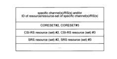
- specific channels/signals, specific channels/signals/resources/resource sets, specific signals, specific channels, specific resources, specific channels/RS resources/resource sets, and specific Channel/RS/resource/resource set and one of PDSCH/PDCCH/CSI-RS/PUSCH/PUCCH/SRS/CORESET may be read interchangeably.
- the particular channel/RS shares the same TCI condition as the target channel, the particular channel/RS shares the indicated TCI condition for the target channel, the TCI of the particular channel/RS
- the state is set/indicated along with the TCI state of the channel of interest, the TCI state of a particular channel/RS references the TCI state of the channel of interest, the TCI state is shared between the particular channel/RS and the channel of interest.
- the same TCI condition is applied between the specific channel/RS and the target channel; the TCI condition of the specific channel/RS is the same as the TCI condition of the target channel; the specific channel/RS that the TCI state of is the same as the unified TCI state, and that the TCI state of a particular channel/RS is updated/indicated/set by the unified TCI state may be read interchangeably.
- the TCI state for a specific channel/RS may be a TCI state for only a specific channel/RS, or may be a unified TCI state.
- This embodiment relates to indicating/setting whether the TCI state of a particular channel/RS is shared with the target channel (whether the TCI state of a particular channel/RS is the same as the unified TCI state).
- the instructions may comply with at least one of the following aspects 1-1 to 1-4.
- TCI status information element TCI status for a particular channel/RS.
- This instruction may follow at least one of the following instruction methods 1-1 to 1-4.
- the indication may be an explicit indication by the RRC configuration indicating, for each TCI state ID, that TCI state is shared with the target channel.
- the TCI state ID may be a joint DL and UL TCI state ID, a DL only TCI state ID, or a UL only TCI state ID.
- the explicit indication may be 1 bit or a flag (Fig. 9). For example, an indication of 0 may indicate that the TCI state is not shared with the channel of interest, and an indication of 1 may indicate that the TCI state is shared with the channel of interest. Each value of the indication may indicate the opposite.
- the explicit indication may be more than one bit.
- the explicit indication may indicate to which channels/RSs/resources/resource sets the TCI state applies/shares. For example, if the explicit indication indicates CORESET #1/#2 and CSI-RS resource #2/#3, then the TCI state applies to the indicated resources.
- the indication may be an explicit indication by the RRC configuration of the list of TCI states shared with the target channel.
- the TCI states in the list may be joint DL and UL TCI state IDs, DL only TCI state IDs, or UL only TCI state IDs. For example, if the explicit indication is a list of TCI state IDs #1, #3, #5, those TCI states are shared with the target channel.
- a TCI state ID may be configured for each specific channel/RS (DL/UL channel/RS).
- the TCI state ID may be a joint DL and UL TCI state ID, a DL only TCI state ID, or a UL only TCI state ID. If the TCI state of a particular channel/RS is set to the same ID as the TCI state of the target channel, it may mean that the TCI state is shared with the target channel. For example, if the same ID of a TCI state is configured in CSI-RS and UE-specific CORESET, it means that TCI state is shared to TCI state in that CSI-RS and UE-specific CORESET. good.
- the indication may be only an indication/setting whether the TCI state for a particular channel/RS is shared with the target channel (sharing indication).
- the indication may not include an explicit association with that TCI state.
- the indication may be one bit that indicates whether the TCI state is shared with the subject channel.
- the indication may apply to all TCI conditions for a particular channel/RS, or may apply to all TCI conditions for a particular channel/RS, including QCL rules (e.g., option A1/A2/B1/B2/B3 above). ) may be applied to all TCI conditions that satisfy The UE may assume that only TCI states that satisfy the QCL rules are shared with the target channel.
- Indication/setting whether the TCI state of a particular channel/RS is shared with the target channel may be done outside each TCI state (TCI state information element, TCI state for a particular channel/RS).
- the indication of whether the TCI state of a particular channel/RS is shared with the target channel may be an implicit indication.
- the indication may be an explicit indication by RRC configuration of a list of resources/resource sets (specific resource/resource set, specific channel/RS resource/resource set) that share the TCI state with the target channel.
- the TCI state for a particular resource/resource set may be shared with the target channel.
- a specific resource/resource set may be a resource/resource set for a specific channel/RS.
- the specific resources/resource sets are aperiodic (AP)-CSI-RS for BM, AP-CSI-RS for CSI, and non-UE-dedicated, cell-specific from the serving cell. ) may include at least one of DL DMRS for PDCCH/PDSCH and AP-SRS for BM.
- FIG. 10 shows an example of a list of specific resources/resource sets.
- the list includes CSI-RS resource (set) #1, #2, #3.
- the TCI state of the target channel may be applied.
- TCI state or a list of TCI states may be established in the 15 TCI state framework.
- the ID/list of TCI states is set by the RRC IE and indicated by the MAC CE/DCI.
- the UE uses the indicated TCI state. Spatial relationships may be used instead of TCI states for the UL.
- a TCI state or a list of TCI states may be established according to at least one of the following instruction methods 2-1 through 2-5.
- TCI states (a specific channel/RS/resource/resource set sharing a unified TCI state for the target channel) enablers (enable information elements) may be configured by RRC parameters.
- An enabler (enable/disable the TCI state of Rel. 17) may be set for each specific channel/RS/resource/resource set.
- Rel When this enabler is set, for a specific channel/RS/resource/resource set/CORESET, Rel. There is no need to indicate 17 TCI state IDs. Rel. for a particular channel/RS/resource/resource set/CORESET. For 17 TCI status indications, a TCI status pool across multiple channels/RSs/resources/resource sets/CORESETs (channels of interest and specific channels/RSs) may be configured.
- the PDSCH configuration (PDSCH-Config) is Rel. 15TCI status list and Rel. 17TCI status list.
- Multiple Rel. 17 TCI state is set, multiple Rel. It may indicate one of the 17 TCI states.
- the indicated TCI state is indicated by higher layer signaling to Rel. 17 TCI state may be used for multiple channels/RSs enabled.
- CORESET setting (ControlResourceSet) #1 is Rel. 15TCI state and Rel. 17 TCI state valid and/or. Rel.
- a TCI State ID is set for each CORESET.
- Rel. 17 TCI states are configured in the PDSCH configuration, so in the CORESET configuration, Rel.
- a flag to enable 17 TCI states is sufficient.
- Multiple Rel. 17 TCI state is set, multiple Rel. It may indicate one of the 17 TCI states.
- Rel In addition to the TCI state pool being configured (eg, within the PDSCH configuration), within the CORESET configuration, Rel. There is no need to indicate the TCI state ID for 17.
- CSI-RS resource set configuration (NZP-CSI-RS-ResourceSet) #1 is Rel. 15TCI state and Rel. 17 TCI state valid and/or. Rel.
- a TCI state ID is configured for each CSI-RS resource set.
- Rel. 17 TCI state the TCI state pool is configured in the PDSCH configuration, so in the CSI-RS resource set configuration, Rel.
- a flag to enable 17 TCI states is sufficient.
- Multiple Rel. 17 TCI state is set, multiple Rel. It may indicate one of the 17 TCI states. Rel. There is no need to indicate the TCI state ID for 17.
- the indicated unified TCI state may apply to a particular channel/RS/resource/resource set.
- An enabler may be configured for each channel/RS/resource/resource set.
- Rel. 17 TCI conditions may not apply.
- Rel. 17 TCI state enablers are set.
- CORESET#1 Rel. 15 TCI state (TCI state #A) is set, and Rel. 15 TCI state (TCI state #B) is set, and Rel. 15 spatial relations (SRS resource #C) are configured.
- FIG. 12 shows an example of the joint TCI state.
- the RRC IE sets up a joint TCI state pool for DL and UL
- the MAC CE indicates/activates the joint TCI state ID for each value (codepoint) of the TCI field
- the DCI indicates one value (011) of the TCI field, which corresponds to TCI state #3.
- the indicated TCI state #3 may be assigned to multiple channels/RS/resources/resource sets (PDSCH, CORESET#2, #3, CSI-RS resource set #2, #3, SRS resource set #2, #3). Applies.
- TCI state/spatial relationships are set for the second resource (other than specific resources, CORESET#1, CSI-RS resource set #1, SRS resource set #1), Rel. 17 TCI conditions may not apply.
- FIG. 13 shows an example of the separate TCI state.
- the RRC IE sets separate TCI state pools for DL and UL
- the MAC CE indicates/indicates the DL TCI state ID/UL TCI state ID for each value (code point) of the TCI field.
- Activate and DCI indicates one value (100) in the TCI field, which corresponds to TCI state #4 for DL and TCI state #5 for UL.
- TCI state #4 applies to multiple DL channels/RS/resources/resource sets (PDSCH, CORESET#2, #3, CSI-RS resource set #2, #3).
- TCI state #5 applies to multiple channels/RS/resources/resource sets (SRS resource set #2, #3) in the UL.
- TCI state/spatial relationships are set for the second resource (other than specific resources, CORESET#1, CSI-RS resource set #1, SRS resource set #1), Rel. 17 TCI conditions may not apply.
- the TCI status pool may be CC-specific or CC-common.
- the TCI status pool may be configured outside the PDSCH configuration.
- joint TCI state or DL TCI state may be applied to a particular channel/RS/resource/resource set. If Rel. If the 15/16 spatial relationship does not exist (and is not configured) (and there are no default beam and PL-RS enablers), then the joint TCI state or UL TCI state is not specified for a particular channel/RS/resource/resource May be applied to sets.
- Rel. At least one of the channel/RS to which the X.17 TCI state applies and the ID of the resource/resource set for that channel/RS may be configured by higher layer signaling. Rel. for the configured channel/RS/resource/resource set. 17 TCI conditions may apply. Rel. 17 TCI state set channel/RS/resource/resource set is Rel. It may be specified that it is not configured with a TCI state/spatial relationship of 15/16.
- Rel. Fifteen TCI state/spatial relationships are not established.
- CORESET#1 Rel. 15 TCI state (TCI state #A) is set, and Rel. 15 TCI state (TCI state #B) is set, and Rel. 15 spatial relations (SRS resource #C) are configured.
- the RRC IE sets up a joint TCI state pool for DL and UL
- the MAC CE indicates/activates the joint TCI state ID for each value (codepoint) of the TCI field
- the DCI indicates one value (011) of the TCI field, which corresponds to TCI state #3.
- the indicated TCI state #3 is Rel. Applies to channel/RS/resource/resource set for which 15 TCI state/spatial relationships are not configured (PDSCH, CORESET#2, #3, CSI-RS resource set #2, #3, SRS resource set #2, #3) be done.
- an ID/list of TCI states may be configured for each specific channel/RS/resource/resource set/CORESET.
- At least one of the specific channel/RS to which the I.17 TCI state applies and the resource/resource set ID of the specific channel/RS (first resource) may be configured by higher layer signaling (FIG. 15). ).
- a specific channel/RS/resource/resource set configured by its higher layer signaling (Rel.17 TCI state applies) is a Rel. It may be configured with a 15/16 TCI state/spatial relationship. In this case, the Rel. 15/16 TCI state/spatial relationships are ignored and Rel. 17 TCI conditions may apply.
- a specific channel/RS/resource/resource set is Rel. It may be indicated/configured whether or not to share the 17 unified TCI states with the target channel. If a particular channel/RS/resource/resource set is Rel. Whether or not the 17 unified TCI states are shared with the channel of interest varies depending on which TCI state is indicated for a particular channel/RS (e.g., value of TCI field, TCI state ID). may be different depending on the resource/resource set applied to a particular channel/RS.
- An enabler is set to activate the 17TCI state.
- the RRC IE sets up a joint TCI state pool and the MAC CE indicates/activates a TCI state from the joint TCI state pool for each value of the TCI field.
- FIG. 16 shows the case where the joint TCI state indicated for a particular channel/RS/resource/resource set is not shared with the target channel.
- DCI indicates one value (100) in the TCI field.
- the indicated TCI state #4 is not shared with the channel of interest.
- TCI state #4 applies to PDSCH and CORESET#2 and does not apply to CSI-RS resource set #2 and SRS resource set #2.
- the most recently used TCI state is maintained.
- FIG. 17 shows the case where the joint TCI state indicated for a particular channel/RS is not shared with the channel of interest.
- DCI indicates one value (011) in the TCI field.
- the indicated TCI state #3 is shared with the channel of interest.
- TCI state #3 applies to PDSCH and CORESET#2 and CSI-RS resource set #2 and SRS resource set #2.
- the QCL rules may be different for Cases 1 and 2 below.
- the RRC IE sets a joint TCI state pool for DL and UL
- the MAC CE indicates/activates the joint TCI state ID for each value (codepoint) of the TCI field
- DCI indicates one value of the TCI field.
- TCI states corresponding to a first range of TCI field values e.g., 000 to 011 are shared with the channel of interest
- TCI states corresponding to a second range of TCI field values e.g., 100 to 111 are: Not shared with target channel. If the DCI indicates a value of 001 within the first range, then options A1/A2 as described above are allowed for the corresponding TCI state #1. Its TCI state #1 is Rel.
- TCI state #1 17 TCI state subject channel/RS/resource/resource set and shared with subject channel. If the DCI dictates a value of 100 in the second range, then the QCL rules in the existing specification (eg options B1/B2/B3 above) are allowed for the corresponding TCI state #4. Its TCI state #4 is Rel. 17 TCI state subject channel/RS/resource/resource set and is not shared with subject channel. In this example, separate TCI states (DL TCI state/UL TCI state) may be used instead of the joint TCI state.
- Only an indication/setting (sharing indication) of whether or not the TCI state for a particular channel/RS is shared with the target channel may be set.
- the indication may not include an explicit association with a resource/resource set.
- the resource/resource set (specific resource/resource set, default resource) to which the directive applies may be specified in the specification.
- the indication may be one bit per channel/RS/BWP/CC indicating whether the TCI state is shared with the target channel. If the TCI status for a particular channel/RS is set to be shared with the target channel, then the TCI status for all resources/resource sets for the particular channel/RS is Rel. 17 TCI status, or the TCI status for a particular resource/resource set within a particular channel/RS resource/resource set is specified in Rel. 17TCI state may be updated/indicated.
- the UE can properly determine whether the TCI state for a particular channel/RS is shared with the target channel.
- This embodiment relates to BFD/RLM.
- a unified TCI state ID (indicating at least one of joint TCI state for DL and UL, TCI state for DL, TCI state for UL) may be set/indicated by RRC IE/MAC CE/DCI.
- how the UE determines the RLM/BFD RS may follow at least one of RLM/BFD RS determination methods 1 and 2 below.
- BFD/RLM RS (explicit BFD/RLM RS) may be indicated by L1 signaling (DCI). If the BFD/RLM RS is not configured, the BFD/RLM RS (implicit BFD/RLM RS) may be derived from the QCL Assumed/TCI State of the CORESET or from the QCL Assumed/TCI State of the Unified/Common TCI State. may be derived.
- BFD/RLM RS may not be indicated by L1 signaling (DCI). If the BFD/RLM RS is not configured, the BFD/RLM RS (implicit BFD/RLM RS) may be derived from the QCL Assumed/TCI State of the CORESET or from the QCL Assumed/TCI State of the Unified/Common TCI State. may be derived.
- DCI L1 signaling
- RLM/BFD RS decision methods joint TCI states and separate TCI states need to be considered. In these RLM/BFD RS determination methods, it is not considered whether the unified TCI state used for RLM/BFD RS determination is shared/configured/indicated with the target channel.
- BFD/RLM RS may be derived from unified TCI state.
- the joint TCI state or the separate TCI state may be switched by the RRC IE (the joint TCI state or the separate TCI state may be set).
- the joint TCI state or the separate TCI state may be set.
- both a joint TCI state or a separate TCI state may be set.
- MAC CE/DCI may choose one of them.
- the BFD/RLM RS may be derived/determined from the joint TCI state.
- the method of determining the BFD/RLM RS from the TCI state may follow either determination method 1 or 2 below.
- the UE may use the TCI state QCL source RS for the BFD/RLM RS. If there are two QCL source RSs (eg, QCL type A RS and QCL type D RS), the UE may use QCL type D RS for BFD/RLM RS.
- QCL source RSs eg, QCL type A RS and QCL type D RS
- the UE may use QCL type D source RSs for BFD/RLM RSs.
- Determination method 1 may be applied to both frequency range (FR) 1 and FR2. Determination method 1 can appropriately determine BFD/RLM RS even when QCL type D RS is not set or is FR1.
- FIG. 19 shows an example in which the joint TCI state is set.
- the RRC IE sets up a joint TCI state pool
- the MAC CE indicates/activates the TCI state corresponding to each value of the TCI field from the joint TCI state pool
- the DCI is one value of the TCI field. to direct.
- a value of 011 in the TCI field indicates TCI state #3.
- TCI state #3 applies to PDSCH.
- TCI state #3 includes a first QCL RS (first QCL type) and a second QCL RS (second QCL type).
- the first QCL RS indicates QCL type A, CSI-RS #3
- the second QCL RS indicates QCL type D, CSI-RS #3.
- the UE may use CSI-RS#3 for BFD RS or CSI-RS#3 for RLM RS.
- the BFD/RLM RS may be derived/determined from the DL TCI state within the separate TCI state for DL/UL.
- FIG. 20 shows an example in which the separate TCI state is set.
- the RRC IE sets a separate TCI state pool
- the MAC CE indicates/activates the DL TCI state/UL TCI state corresponding to each value of the TCI field from the separate TCI state pool
- the DCI Indicates the value of one of the fields.
- a value of 100 in the TCI field indicates DL TCI state #4 and UL TCI state #5.
- TCI state #4 applies to PDSCH.
- TCI state #4 includes a first QCL RS (first QCL type) and a second QCL RS (second QCL type).
- the first QCL RS indicates QCL type A, CSI-RS#4, and the second QCL RS indicates QCL type D, CSI-RS#4.
- the UE may use CSI-RS#4 for BFD RS or CSI-RS#4 for RLM RS.
- This aspect may be applied only when an explicit BFD/RLM RS is not configured.
- An explicit RRC parameter may be configured that indicates whether a certain unified TCI state is shared with the target channel.
- a unified TCI state for Case 1 only may be considered a BFD/RLM RS.
- the failure can be detected by the BFD/RLM.
- Unified TCI state for case 2 only may be considered as BFD/RLM RS.
- Both case 1 and 2 unified TCI states may be considered as BFD/RLM RS. Whatever TCI state is indicated, the latest TCI state is used for BFD/RLM RS.
- the unified TCI state may be a joint TCI state for DL and UL or a TCI state for DL.
- the RSs within that TCI state may be considered BFD/RLM RSs.
- an RS within that TCI state may be considered a BFD/RLM RS.
- TCI state for CORESET is Rel. 17 unified TCI states or Rel. All RSs in a TCI state of 15/16 may be considered BFD/RLM RSs, regardless of whether they are in that TCI state.
- the UE selects Rel.
- a CORESET with 17 unified TCI states may be given higher priority.
- the UE can properly determine BFD/RLM even when using the unified TCI state.
- This embodiment relates to new beam detection (NBI).
- the CORESET/PUCCH beam is updated to q_new. If the BFR is not completed, the UE may not be able to transmit or receive control information on the obstructing beam, as the BFR will be performed again based on the obstructing beam.
- the beam application timing based on BFR completion may follow at least one of timings 1 to 4 below.
- TCI 4 In TRP-specific BFR on SpCell/SCell (Rel.17), after receiving a BFR response, updating the QCL assumptions for CORESET with 2 activated TCI states for per-cell BFR with 2 activated
- the CORESET with the TCI state associated with the TCI state may be updated to have one TCI state associated with the failed BFD-RS set, for per-TRP BFR in single DCI-based multi-TRP.
- the TCI state may be updated, and for per-TRP BFR in multi-DCI-based multi-TRP, after receiving the BFR response, the TCI associated with the failed BFD-RS set/CORESET pool index It may be that the state is updated.
- the beam application timing within the unified TCI state may be Y symbols after the ACK for beam indication (the first slot after at least Y symbols of the last symbol of the ACK for joint or separate DL/UL beam indication).
- Y may be based on the minimum subcarrier spacing (SCS) within the CC (cell) to which the beam applies.
- SCS subcarrier spacing
- Y may be given by the RRC parameter beam application time (BAT, eg, BeamAppTime_r17).
- BFR completion reception of a response to BFR (BFR response (BFRR)), and the last symbol of a specific DCI format for BFR may be read interchangeably.
- the particular DCI format may be the DCI format in at least one of timings 1 through 3 above.
- the new/updated QCL source RS is the channel of interest in the CC and the Rel. channel/signal (a particular channel/RS) configured to share 17 TCI states.
- Y for Y symbols from BFR completion to unified TCI state update may be set by RRC, reported as a UE capability, or specified in the specification.
- Y may be common to multiple SCSs, or may be different values depending on the SCSs.
- Y may be the same value as Y for beam application timing.
- the new/updated QCL source RS may be applied to all or part of the PDCCH/PDSCH/PUCCH/PUSCH after Y symbols after the UE receives the BFR response.
- q_new may apply to all BWP/CCs in the CC list or to all BWP/CCs in the TCI state pool. May be applied to all BWP/CCs within the BFR MAC CE.
- the CA case may be when a simultaneous beam update list (CC-list) is configured, or when a CC common TCI state pool is configured, or when a BFR MAC CE has multiple beam failures. may be included in the CC.
- q_new may be applied to all BWP/CCs in CCs reported as faulty CCs in BFR MAC CE.
- the UE detects beam failures in each of CC #1, #2, and #3, and the UE detects CSI- RS#1-1, #2-1, and #3-1 are reported respectively. After Y symbols from completion of BFR, the UE applies CSI-RS #1-1, #2-1, and #3-1 as unified TCI states to CC #1, #2, and #3, respectively.
- the q_new RS may be a CC-common RS (eg, BFR RS) or a CC-specific RS.
- BFR RS CC-common RS
- CC-specific RSs the NBI RS for each CC reported in the BFR MAC CE may be used for q_new.
- CC-List Simultaneous Beam Update List
- CC-Common TCI Status Pool a beam failure is detected in some CCs within the same CC as the CCs in that list/pool.
- the UE may follow either of update actions 1 and 2 if no beam failure is detected on any other CC.
- the beams of all CCs in the CC list/TCI state pool may be updated to q_new.
- the UE may determine q_new for each BWP/CC according to at least one of derivation methods 1 and 2 below.
- CC common q_new The q_new RS of the BWP/CC with beam failure is used for all BWP/CCs in the same CC list/TCI status pool.
- CC-specific q_new The RS index of the q_new of the BWP/CC with beam failure is used for all BWP/CCs in the same CC list/TCI state pool. For example, if CSI-RS #1 in BWP #1 in CC #1 is determined for CC #1, then for all other CCs, CSI-RS in BWP #1 of each BB may be used.
- the CC list/TCI status pool indicates CC #1, #2, and #3.
- the UE detects a beam failure in CC#1, and the UE uses CSI-RS#1-1 (CSI-RS of index #1 in CC#1) as the NBI for CC#1 in BFR MAC CE. Report. After Y symbols from the completion of BFR, the reported CSI-RS # 1-1 is applied as the unified TCI state for CC # 1, and CSI-RS # 2-1 (CC # 2 CSI-RS with the same index #1 in CC#3) is applied, and CSI-RS#3-1 (CSI-RS with the same index #1 in CC#3) is applied as the unified TCI state for CC#3.
- the UE may report the impaired CC and NBI by contention-free random access (CFRA) or CBRA BFR instead of BFR MAC CE.
- CFRA contention-free random access
- ⁇ Mode 3-3>> For a given unified TCI state, there may be two cases: [Case 1] The unified TCI state is shared/set/indicated with the channel of interest. [Case 2] Its unified TCI state is not shared/set/indicated with the channel of interest.
- An explicit RRC parameter may be configured that indicates whether a certain unified TCI state is shared with the target channel.
- aspects 3-1/3-2 may be applied to the unified TCI state of Case 1 only.
- Rel Similar to the 15/16 TCI state, the unified TCI state used for the target channel (eg, UE-specific PDCCH/PUCCH) is updated to q_new.
- the target channel eg, UE-specific PDCCH/PUCCH
- TCI state for CORESET is Rel. 17 unified TCI states or Rel.
- the QCL assumption for CORESET/PUCCH may be updated to q_new regardless of the TCI state of 15/16.
- the UE may follow any of separate TCI state update operations 1 to 3 below.
- TCI state update operation 3 is preferred.
- the UE may set (initialize) all or part of the power control parameters of PUCCH/PUSCH/SRS to specific values (initial values).
- the PUCCH power control parameters are initialized after BFR is completed.
- the power control parameters of the PUCCH/PUSCH/SRS configured with (associated with) the 17 unified TCI states may be set (initialized) to specific values.
- the cumulative value of TPC commands for closed-loop power control of PUCCH/PUSCH/SRS may be set to 0 (initialized).
- the UE can properly determine BFD/RLM even when using the unified TCI state.
- This embodiment relates to a method for setting a unified TCI state (joint TCI state or separate TCI state).
- the TCI status pool may be set for each CC (as a CC-specific TCI status pool) or across multiple CCs (as a CC-common TCI status pool).
- One of the joint TCI state and the separate TCI state can be set by the RRC IE on a per-UE/per-cell-group/per-CC/per-BWP basis.
- a joint TCI state (pool) is set for BWP#1 in CC#1
- a separate TCI state (pool) is set for BWP#1 in CC#2.
- constraints 1 and 2 may be required.
- the unified TCI state can be set appropriately.
- This embodiment relates to a method for setting the TCI state in BWP/CC.
- TCI state setting method 1 Rel. 15/16 TCI state/space relationship and Rel. 17 unified TCI states can be set to the same BWP/CC or different BWP/CCs.
- TCI status setting method 2 Rel. 15/16 TCI state/space relationship and Rel. 17 unified TCI states cannot both be set to the same BWP/CC or to different BWP/CCs. Rel. for any CC. 17 unified TCI states are configured in the UE, Rel. It may be specified that the 15/16 TCI state/spatial relationship is not configured for that UE.
- the TCI state can be set appropriately.
- RRC IE Radio Resource Control IE
- a higher layer parameter may indicate whether to enable the feature.
- UE capabilities may indicate whether the UE supports the feature.
- a UE for which a higher layer parameter corresponding to that function is set may perform that function. It may be defined that "UEs for which upper layer parameters corresponding to the function are not set shall not perform the function (for example, according to Rel. 15/16)".
- a UE that has reported/transmitted a UE capability indicating that it supports that function may perform that function. It may be specified that "a UE that does not report UE capabilities indicating that it supports the feature shall not perform that feature (eg according to Rel. 15/16)".
- a UE may perform a function if it reports/transmits a UE capability indicating that it supports the function and the higher layer parameters corresponding to the function are configured. "If the UE does not report/transmit a UE capability indicating that it supports the function, or if the higher layer parameters corresponding to the function are not configured, the UE does not perform the function (e.g., Rel. 15/ 16) may be defined.
- Which embodiment/option/choice/function among the above multiple embodiments is used may be set by higher layer parameters, may be reported by the UE as UE capabilities, or may be specified in the specification. It may be specified or determined by reported UE capabilities and higher layer parameter settings.
- Unified TCI Framework at least one of Joint TCI State Pool, Separate TCI State Pool, Joint TCI State Pool Beam Direction, Separate TCI State Beam Direction.
- the UE capability is defined by the maximum number of unified TCI states configured by the RRC IE (the number supported by the UE), the maximum number of TCI states configured for joint beam indication, the maximum number of UL TCI states for separate beam indication ( number supported by the UE), maximum number of DL TCI states for separate beam indication.
- UE capabilities are maximum number of active TCI states (number supported by UE) for unified TCI state (common beam indication), maximum number of active TCI states for joint beam indication (number supported by UE), for separate beam indication maximum number of active UL TCI states for separate beam indication (the number supported by the UE).
- - Rel. shared with a particular resource.
- the specific resource may be at least one of UE dedicated reception on PDSCH/PDCCH, PUSCH for dynamic grant/configured grant, and dedicated PUCCH resource. - Rel. not shared with a specific resource. 17 TCI State (Unified TCI State).
- the specific resource may be at least one of UE dedicated reception on PDSCH/PDCCH, PUSCH for dynamic grant/configured grant, and dedicated PUCCH resource.
- BFR for unified TCI states.
- the UE can implement the above functions while maintaining compatibility with existing specifications.
- wireless communication system A configuration of a wireless communication system according to an embodiment of the present disclosure will be described below.
- communication is performed using any one of the radio communication methods according to the above embodiments of the present disclosure or a combination thereof.
- FIG. 24 is a diagram showing an example of a schematic configuration of a wireless communication system according to one embodiment.
- the wireless communication system 1 may be a system that realizes communication using Long Term Evolution (LTE), 5th generation mobile communication system New Radio (5G NR), etc. specified by the Third Generation Partnership Project (3GPP). .
- LTE Long Term Evolution
- 5G NR 5th generation mobile communication system New Radio
- 3GPP Third Generation Partnership Project
- the wireless communication system 1 may also support dual connectivity between multiple Radio Access Technologies (RATs) (Multi-RAT Dual Connectivity (MR-DC)).
- RATs Radio Access Technologies
- MR-DC is dual connectivity between LTE (Evolved Universal Terrestrial Radio Access (E-UTRA)) and NR (E-UTRA-NR Dual Connectivity (EN-DC)), dual connectivity between NR and LTE (NR-E -UTRA Dual Connectivity (NE-DC)), etc.
- RATs Radio Access Technologies
- MR-DC is dual connectivity between LTE (Evolved Universal Terrestrial Radio Access (E-UTRA)) and NR (E-UTRA-NR Dual Connectivity (EN-DC)), dual connectivity between NR and LTE (NR-E -UTRA Dual Connectivity (NE-DC)), etc.
- LTE Evolved Universal Terrestrial Radio Access
- EN-DC E-UTRA-NR Dual Connectivity
- NE-DC NR-E -UTRA Dual Connectivity
- the LTE (E-UTRA) base station (eNB) is the master node (MN), and the NR base station (gNB) is the secondary node (SN).
- the NR base station (gNB) is the MN, and the LTE (E-UTRA) base station (eNB) is the SN.
- the wireless communication system 1 has dual connectivity between multiple base stations within the same RAT (for example, dual connectivity (NR-NR Dual Connectivity (NN-DC) in which both MN and SN are NR base stations (gNB) )) may be supported.
- dual connectivity NR-NR Dual Connectivity (NN-DC) in which both MN and SN are NR base stations (gNB)
- gNB NR base stations
- a wireless communication system 1 includes a base station 11 forming a macrocell C1 with a relatively wide coverage, and base stations 12 (12a-12c) arranged in the macrocell C1 and forming a small cell C2 narrower than the macrocell C1. You may prepare.
- a user terminal 20 may be located within at least one cell. The arrangement, number, etc. of each cell and user terminals 20 are not limited to the embodiment shown in the figure.
- the base stations 11 and 12 are collectively referred to as the base station 10 when not distinguished.
- the user terminal 20 may connect to at least one of the multiple base stations 10 .
- the user terminal 20 may utilize at least one of carrier aggregation (CA) using a plurality of component carriers (CC) and dual connectivity (DC).
- CA carrier aggregation
- CC component carriers
- DC dual connectivity
- Each CC may be included in at least one of the first frequency band (Frequency Range 1 (FR1)) and the second frequency band (Frequency Range 2 (FR2)).
- Macrocell C1 may be included in FR1, and small cell C2 may be included in FR2.
- FR1 may be a frequency band below 6 GHz (sub-6 GHz)
- FR2 may be a frequency band above 24 GHz (above-24 GHz). Note that the frequency bands and definitions of FR1 and FR2 are not limited to these, and for example, FR1 may correspond to a higher frequency band than FR2.
- the user terminal 20 may communicate using at least one of Time Division Duplex (TDD) and Frequency Division Duplex (FDD) in each CC.
- TDD Time Division Duplex
- FDD Frequency Division Duplex
- a plurality of base stations 10 may be connected by wire (for example, an optical fiber conforming to Common Public Radio Interface (CPRI), X2 interface, etc.) or wirelessly (for example, NR communication).
- wire for example, an optical fiber conforming to Common Public Radio Interface (CPRI), X2 interface, etc.
- NR communication for example, when NR communication is used as a backhaul between the base stations 11 and 12, the base station 11 corresponding to the upper station is an Integrated Access Backhaul (IAB) donor, and the base station 12 corresponding to the relay station (relay) is an IAB Also called a node.
- IAB Integrated Access Backhaul
- relay station relay station
- the base station 10 may be connected to the core network 30 directly or via another base station 10 .
- the core network 30 may include, for example, at least one of Evolved Packet Core (EPC), 5G Core Network (5GCN), Next Generation Core (NGC), and the like.
- EPC Evolved Packet Core
- 5GCN 5G Core Network
- NGC Next Generation Core
- the user terminal 20 may be a terminal compatible with at least one of communication schemes such as LTE, LTE-A, and 5G.
- a radio access scheme based on orthogonal frequency division multiplexing may be used.
- OFDM orthogonal frequency division multiplexing
- CP-OFDM Cyclic Prefix OFDM
- DFT-s-OFDM Discrete Fourier Transform Spread OFDM
- OFDMA Orthogonal Frequency Division Multiple Access
- SC-FDMA Single Carrier Frequency Division Multiple Access
- a radio access method may be called a waveform.
- other radio access schemes for example, other single-carrier transmission schemes and other multi-carrier transmission schemes
- the UL and DL radio access schemes may be used as the UL and DL radio access schemes.
- a downlink shared channel Physical Downlink Shared Channel (PDSCH)
- PDSCH Physical Downlink Shared Channel
- PBCH Physical Broadcast Channel
- PDCCH Physical Downlink Control Channel
- an uplink shared channel (PUSCH) shared by each user terminal 20 an uplink control channel (PUCCH), a random access channel (Physical Random Access Channel (PRACH)) or the like may be used.
- PUSCH uplink shared channel
- PUCCH uplink control channel
- PRACH Physical Random Access Channel
- User data, upper layer control information, System Information Block (SIB), etc. are transmitted by the PDSCH.
- User data, higher layer control information, and the like may be transmitted by PUSCH.
- a Master Information Block (MIB) may be transmitted by the PBCH.
- Lower layer control information may be transmitted by the PDCCH.
- the lower layer control information may include, for example, downlink control information (DCI) including scheduling information for at least one of PDSCH and PUSCH.
- DCI downlink control information
- the DCI that schedules PDSCH may be called DL assignment, DL DCI, etc.
- the DCI that schedules PUSCH may be called UL grant, UL DCI, etc.
- PDSCH may be replaced with DL data
- PUSCH may be replaced with UL data.
- a control resource set (CControl Resource SET (CORESET)) and a search space (search space) may be used for PDCCH detection.
- CORESET corresponds to a resource searching for DCI.
- the search space corresponds to the search area and search method of PDCCH candidates.
- a CORESET may be associated with one or more search spaces. The UE may monitor CORESETs associated with certain search spaces based on the search space settings.
- One search space may correspond to PDCCH candidates corresponding to one or more aggregation levels.
- One or more search spaces may be referred to as a search space set. Note that “search space”, “search space set”, “search space setting”, “search space set setting”, “CORESET”, “CORESET setting”, etc. in the present disclosure may be read interchangeably.
- PUCCH channel state information
- acknowledgment information for example, Hybrid Automatic Repeat reQuest ACKnowledgement (HARQ-ACK), ACK/NACK, etc.
- SR scheduling request
- a random access preamble for connection establishment with a cell may be transmitted by the PRACH.
- downlink, uplink, etc. may be expressed without adding "link”.
- various channels may be expressed without adding "Physical" to the head.
- synchronization signals SS
- downlink reference signals DL-RS
- the DL-RS includes a cell-specific reference signal (CRS), a channel state information reference signal (CSI-RS), a demodulation reference signal (DeModulation Reference Signal (DMRS)), Positioning Reference Signal (PRS)), Phase Tracking Reference Signal (PTRS)), etc.
- CRS cell-specific reference signal
- CSI-RS channel state information reference signal
- DMRS Demodulation reference signal
- PRS Positioning Reference Signal
- PTRS Phase Tracking Reference Signal
- the synchronization signal may be, for example, at least one of a Primary Synchronization Signal (PSS) and a Secondary Synchronization Signal (SSS).
- PSS Primary Synchronization Signal
- SSS Secondary Synchronization Signal
- a signal block including SS (PSS, SSS) and PBCH (and DMRS for PBCH) may be called SS/PBCH block, SS Block (SSB), and so on.
- SS, SSB, etc. may also be referred to as reference signals.
- DMRS may also be called a user terminal-specific reference signal (UE-specific reference signal).
- FIG. 25 is a diagram illustrating an example of the configuration of a base station according to one embodiment.
- the base station 10 comprises a control section 110 , a transmission/reception section 120 , a transmission/reception antenna 130 and a transmission line interface 140 .
- One or more of each of the control unit 110, the transmitting/receiving unit 120, the transmitting/receiving antenna 130, and the transmission line interface 140 may be provided.
- this example mainly shows the functional blocks that characterize the present embodiment, and it may be assumed that the base station 10 also has other functional blocks necessary for wireless communication. A part of the processing of each unit described below may be omitted.
- the control unit 110 controls the base station 10 as a whole.
- the control unit 110 can be configured from a controller, a control circuit, and the like, which are explained based on common recognition in the technical field according to the present disclosure.
- the control unit 110 may control signal generation, scheduling (eg, resource allocation, mapping), and the like.
- the control unit 110 may control transmission/reception, measurement, etc. using the transmission/reception unit 120 , the transmission/reception antenna 130 and the transmission line interface 140 .
- the control unit 110 may generate data to be transmitted as a signal, control information, a sequence, etc., and transfer them to the transmission/reception unit 120 .
- the control unit 110 may perform call processing (setup, release, etc.) of communication channels, state management of the base station 10, management of radio resources, and the like.
- the transmitting/receiving section 120 may include a baseband section 121 , a radio frequency (RF) section 122 and a measuring section 123 .
- the baseband section 121 may include a transmission processing section 1211 and a reception processing section 1212 .
- the transmitting/receiving unit 120 is configured from a transmitter/receiver, an RF circuit, a baseband circuit, a filter, a phase shifter, a measurement circuit, a transmitting/receiving circuit, etc., which are explained based on common recognition in the technical field according to the present disclosure. be able to.
- the transmission/reception unit 120 may be configured as an integrated transmission/reception unit, or may be configured from a transmission unit and a reception unit.
- the transmission section may be composed of the transmission processing section 1211 and the RF section 122 .
- the receiving section may be composed of a reception processing section 1212 , an RF section 122 and a measurement section 123 .
- the transmitting/receiving antenna 130 can be configured from an antenna described based on common recognition in the technical field related to the present disclosure, such as an array antenna.
- the transmitting/receiving unit 120 may transmit the above-described downlink channel, synchronization signal, downlink reference signal, and the like.
- the transmitting/receiving unit 120 may receive the above-described uplink channel, uplink reference signal, and the like.
- the transmitting/receiving unit 120 may form at least one of the transmission beam and the reception beam using digital beamforming (eg, precoding), analog beamforming (eg, phase rotation), or the like.
- digital beamforming eg, precoding
- analog beamforming eg, phase rotation
- the transmission/reception unit 120 (transmission processing unit 1211) performs Packet Data Convergence Protocol (PDCP) layer processing, Radio Link Control (RLC) layer processing (for example, RLC retransmission control), Medium Access Control (MAC) layer processing (for example, HARQ retransmission control), etc. may be performed to generate a bit string to be transmitted.
- PDCP Packet Data Convergence Protocol
- RLC Radio Link Control
- MAC Medium Access Control
- HARQ retransmission control for example, HARQ retransmission control
- the transmission/reception unit 120 (transmission processing unit 1211) performs channel coding (which may include error correction coding), modulation, mapping, filtering, and discrete Fourier transform (DFT) on the bit string to be transmitted. Processing (if necessary), Inverse Fast Fourier Transform (IFFT) processing, precoding, transmission processing such as digital-to-analog conversion may be performed, and the baseband signal may be output.
- channel coding which may include error correction coding
- modulation modulation
- mapping mapping
- filtering filtering
- DFT discrete Fourier transform
- DFT discrete Fourier transform
- the transmitting/receiving unit 120 may perform modulation to a radio frequency band, filter processing, amplification, and the like on the baseband signal, and may transmit the radio frequency band signal via the transmitting/receiving antenna 130. .
- the transmitting/receiving unit 120 may perform amplification, filtering, demodulation to a baseband signal, etc. on the radio frequency band signal received by the transmitting/receiving antenna 130.
- the transmission/reception unit 120 (reception processing unit 1212) performs analog-to-digital conversion, Fast Fourier transform (FFT) processing, and Inverse Discrete Fourier transform (IDFT) processing on the acquired baseband signal. )) processing (if necessary), filtering, demapping, demodulation, decoding (which may include error correction decoding), MAC layer processing, RLC layer processing and PDCP layer processing. User data and the like may be acquired.
- FFT Fast Fourier transform
- IDFT Inverse Discrete Fourier transform
- the transmitting/receiving unit 120 may measure the received signal.
- the measurement unit 123 may perform Radio Resource Management (RRM) measurement, Channel State Information (CSI) measurement, etc. based on the received signal.
- the measurement unit 123 measures received power (for example, Reference Signal Received Power (RSRP)), reception quality (for example, Reference Signal Received Quality (RSRQ), Signal to Interference plus Noise Ratio (SINR), Signal to Noise Ratio (SNR)) , signal strength (for example, Received Signal Strength Indicator (RSSI)), channel information (for example, CSI), and the like may be measured.
- RSRP Reference Signal Received Power
- RSSQ Reference Signal Received Quality
- SINR Signal to Noise Ratio
- RSSI Received Signal Strength Indicator
- channel information for example, CSI
- the transmission path interface 140 transmits and receives signals (backhaul signaling) to and from devices included in the core network 30, other base stations 10, etc., and user data (user plane data) for the user terminal 20, control plane data, and the like. Data and the like may be obtained, transmitted, and the like.
- the transmitter and receiver of the base station 10 in the present disclosure may be configured by at least one of the transmitter/receiver 120, the transmitter/receiver antenna 130, and the transmission line interface 140.
- the transmitting/receiving unit 120 may transmit settings related to the transmission configuration indication (TCI) state applied to at least one of multiple types of channels and signals.
- the controller 110 may determine whether the TCI state is shared with a specific signal.
- the transmitting/receiving unit 120 may transmit an indication regarding a transmission configuration indication (TCI) state that applies to multiple types of at least one of channels and signals.
- TCI transmission configuration indication
- the controller 110 may control beam failure detection and radio link monitoring using reference signals based on the TCI state.
- the transmitting/receiving unit 120 may transmit a plurality of settings respectively corresponding to a plurality of cells.
- the control unit 110 may apply the transmission configuration indication (TCI) state indicated in the corresponding configuration to each cell.
- TCI transmission configuration indication
- Each setting includes at least one of whether the corresponding TCI state applies to both downlink and uplink, and whether the corresponding TCI state applies to multiple types of at least one of channels and signals. may contain one.
- FIG. 26 is a diagram illustrating an example of the configuration of a user terminal according to an embodiment.
- the user terminal 20 includes a control section 210 , a transmission/reception section 220 and a transmission/reception antenna 230 .
- One or more of each of the control unit 210, the transmitting/receiving unit 220, and the transmitting/receiving antenna 230 may be provided.
- this example mainly shows the functional blocks of the features of the present embodiment, and it may be assumed that the user terminal 20 also has other functional blocks necessary for wireless communication. A part of the processing of each unit described below may be omitted.
- the control unit 210 controls the user terminal 20 as a whole.
- the control unit 210 can be configured from a controller, a control circuit, and the like, which are explained based on common recognition in the technical field according to the present disclosure.
- the control unit 210 may control signal generation, mapping, and the like.
- the control unit 210 may control transmission/reception, measurement, etc. using the transmission/reception unit 220 and the transmission/reception antenna 230 .
- the control unit 210 may generate data, control information, sequences, etc. to be transmitted as signals, and transfer them to the transmission/reception unit 220 .
- the transmitting/receiving section 220 may include a baseband section 221 , an RF section 222 and a measurement section 223 .
- the baseband section 221 may include a transmission processing section 2211 and a reception processing section 2212 .
- the transmitting/receiving unit 220 can be configured from a transmitter/receiver, an RF circuit, a baseband circuit, a filter, a phase shifter, a measurement circuit, a transmitting/receiving circuit, etc., which are explained based on common recognition in the technical field according to the present disclosure.
- the transmission/reception unit 220 may be configured as an integrated transmission/reception unit, or may be configured from a transmission unit and a reception unit.
- the transmission section may be composed of a transmission processing section 2211 and an RF section 222 .
- the receiving section may include a reception processing section 2212 , an RF section 222 and a measurement section 223 .
- the transmitting/receiving antenna 230 can be configured from an antenna described based on common recognition in the technical field related to the present disclosure, such as an array antenna.
- the transmitting/receiving unit 220 may receive the above-described downlink channel, synchronization signal, downlink reference signal, and the like.
- the transmitting/receiving unit 220 may transmit the above-described uplink channel, uplink reference signal, and the like.
- the transmitter/receiver 220 may form at least one of the transmission beam and the reception beam using digital beamforming (eg, precoding), analog beamforming (eg, phase rotation), or the like.
- digital beamforming eg, precoding
- analog beamforming eg, phase rotation
- the transmission/reception unit 220 (transmission processing unit 2211) performs PDCP layer processing, RLC layer processing (for example, RLC retransmission control), MAC layer processing (for example, for data and control information acquired from the control unit 210, for example , HARQ retransmission control), etc., to generate a bit string to be transmitted.
- RLC layer processing for example, RLC retransmission control
- MAC layer processing for example, for data and control information acquired from the control unit 210, for example , HARQ retransmission control
- the transmitting/receiving unit 220 (transmission processing unit 2211) performs channel coding (which may include error correction coding), modulation, mapping, filtering, DFT processing (if necessary), and IFFT processing on a bit string to be transmitted. , precoding, digital-analog conversion, and other transmission processing may be performed, and the baseband signal may be output.
- Whether or not to apply DFT processing may be based on transform precoding settings. Transmitting/receiving unit 220 (transmission processing unit 2211), for a certain channel (for example, PUSCH), if transform precoding is enabled, the above to transmit the channel using the DFT-s-OFDM waveform
- the DFT process may be performed as the transmission process, or otherwise the DFT process may not be performed as the transmission process.
- the transmitting/receiving unit 220 may perform modulation to a radio frequency band, filter processing, amplification, and the like on the baseband signal, and may transmit the radio frequency band signal via the transmitting/receiving antenna 230. .
- the transmitting/receiving section 220 may perform amplification, filtering, demodulation to a baseband signal, etc. on the radio frequency band signal received by the transmitting/receiving antenna 230.
- the transmission/reception unit 220 (reception processing unit 2212) performs analog-to-digital conversion, FFT processing, IDFT processing (if necessary), filtering, demapping, demodulation, decoding (error correction) on the acquired baseband signal. decoding), MAC layer processing, RLC layer processing, PDCP layer processing, and other reception processing may be applied to acquire user data and the like.
- the transmitting/receiving section 220 may measure the received signal.
- the measurement unit 223 may perform RRM measurement, CSI measurement, etc. based on the received signal.
- the measuring unit 223 may measure received power (eg, RSRP), received quality (eg, RSRQ, SINR, SNR), signal strength (eg, RSSI), channel information (eg, CSI), and the like.
- the measurement result may be output to control section 210 .
- the transmitter and receiver of the user terminal 20 in the present disclosure may be configured by at least one of the transmitter/receiver 220 and the transmitter/receiver antenna 230 .
- Transmitter/receiver 220 may receive settings related to transmission configuration indication (TCI) states that apply to multiple types of at least one of channels and signals. Controller 210 may determine whether the TCI state is shared with a particular signal.
- TCI transmission configuration indication
- the setting may indicate whether the TCI state is shared with the specific signal.
- the controller 210 may determine whether the TCI state is shared with the specific signal based on the setting.
- the setting may indicate a resource or resource set in which the TCI state is shared with the specific signal.
- the setting may indicate that no TCI state applies to one type of channel or signal.
- Transmitter/receiver 220 may receive an indication regarding a transmission configuration indication (TCI) state that applies to multiple types of at least one of channels and signals.
- the controller 210 may determine reference signals for beam failure detection and radio link monitoring based on the TCI state.
- TCI transmission configuration indication
- the reference signal may be the joint TCI state.
- the reference signal may be the downlink TCI state.
- the controller 210 When the transceiver 220 receives a list of cells, detects a failure in at least one of the plurality of cells, and reports a new beam, the controller 210 performs the to determine a plurality of TCI states to be used for each of the plurality of cells.
- the transmitting/receiving unit 220 may receive a plurality of settings respectively corresponding to a plurality of cells.
- the control unit 210 may apply the transmission configuration indication (TCI) state indicated in the corresponding configuration to each cell.
- TCI transmission configuration indication
- Each setting includes at least one of whether the corresponding TCI state applies to both downlink and uplink, and whether the corresponding TCI state applies to multiple types of at least one of channels and signals. may contain one.
- Each setting may indicate one of a TCI state that applies to both the downlink and uplink, or a downlink TCI state that applies to the downlink and an uplink TCI state that applies to the uplink.
- the plurality of settings may include a setting indicating TCI conditions applied to multiple types of at least one of channels and signals, and a setting indicating TCI conditions applied to one type of channel or signal.
- the plurality of settings include settings indicating TCI conditions that apply to at least one type of channel and signal
- the plurality of settings are settings that indicate TCI conditions that apply to one type of channel or signal. may not contain
- each functional block may be implemented using one device that is physically or logically coupled, or directly or indirectly using two or more devices that are physically or logically separated (e.g. , wired, wireless, etc.) and may be implemented using these multiple devices.
- a functional block may be implemented by combining software in the one device or the plurality of devices.
- function includes judgment, decision, determination, calculation, calculation, processing, derivation, investigation, search, confirmation, reception, transmission, output, access, resolution, selection, selection, establishment, comparison, assumption, expectation, deem , broadcasting, notifying, communicating, forwarding, configuring, reconfiguring, allocating, mapping, assigning, etc.
- a functional block (component) that performs transmission may be called a transmitting unit, a transmitter, or the like. In either case, as described above, the implementation method is not particularly limited.
- a base station, a user terminal, etc. in an embodiment of the present disclosure may function as a computer that performs processing of the wireless communication method of the present disclosure.
- FIG. 27 is a diagram illustrating an example of hardware configurations of a base station and a user terminal according to an embodiment.
- the base station 10 and user terminal 20 described above may be physically configured as a computer device including a processor 1001, a memory 1002, a storage 1003, a communication device 1004, an input device 1005, an output device 1006, a bus 1007, and the like. .
- the hardware configuration of the base station 10 and the user terminal 20 may be configured to include one or more of each device shown in the figure, or may be configured without some devices.
- processor 1001 may be implemented by one or more chips.
- predetermined software program
- the processor 1001 performs calculations, communication via the communication device 1004 and at least one of reading and writing data in the memory 1002 and the storage 1003 .
- the processor 1001 operates an operating system and controls the entire computer.
- the processor 1001 may be configured by a central processing unit (CPU) including an interface with peripheral devices, a control device, an arithmetic device, registers, and the like.
- CPU central processing unit
- control unit 110 210
- transmission/reception unit 120 220
- FIG. 10 FIG. 10
- the processor 1001 reads programs (program codes), software modules, data, etc. from at least one of the storage 1003 and the communication device 1004 to the memory 1002, and executes various processes according to them.
- programs program codes
- software modules software modules
- data etc.
- the control unit 110 (210) may be implemented by a control program stored in the memory 1002 and running on the processor 1001, and other functional blocks may be similarly implemented.
- the memory 1002 is a computer-readable recording medium, such as Read Only Memory (ROM), Erasable Programmable ROM (EPROM), Electrically EPROM (EEPROM), Random Access Memory (RAM), or at least any other suitable storage medium. may be configured by one.
- the memory 1002 may also be called a register, cache, main memory (main storage device), or the like.
- the memory 1002 can store executable programs (program code), software modules, etc. for implementing a wireless communication method according to an embodiment of the present disclosure.
- the storage 1003 is a computer-readable recording medium, for example, a flexible disk, a floppy (registered trademark) disk, a magneto-optical disk (for example, a compact disk (Compact Disc ROM (CD-ROM), etc.), a digital versatile disk, Blu-ray disc), removable disc, hard disk drive, smart card, flash memory device (e.g., card, stick, key drive), magnetic stripe, database, server, or other suitable storage medium may be configured by Storage 1003 may also be called an auxiliary storage device.
- a computer-readable recording medium for example, a flexible disk, a floppy (registered trademark) disk, a magneto-optical disk (for example, a compact disk (Compact Disc ROM (CD-ROM), etc.), a digital versatile disk, Blu-ray disc), removable disc, hard disk drive, smart card, flash memory device (e.g., card, stick, key drive), magnetic stripe, database, server, or other suitable storage medium may be configured by Storage 1003 may also
- the communication device 1004 is hardware (transmitting/receiving device) for communicating between computers via at least one of a wired network and a wireless network, and is also called a network device, a network controller, a network card, a communication module, or the like.
- the communication device 1004 includes a high-frequency switch, duplexer, filter, frequency synthesizer, etc. in order to realize at least one of frequency division duplex (FDD) and time division duplex (TDD), for example. may be configured to include
- the transmitting/receiving unit 120 (220), the transmitting/receiving antenna 130 (230), and the like described above may be realized by the communication device 1004.
- the transmitter/receiver 120 (220) may be physically or logically separated into a transmitter 120a (220a) and a receiver 120b (220b).
- the input device 1005 is an input device (for example, keyboard, mouse, microphone, switch, button, sensor, etc.) that receives input from the outside.
- the output device 1006 is an output device (for example, a display, a speaker, a Light Emitting Diode (LED) lamp, etc.) that outputs to the outside. Note that the input device 1005 and the output device 1006 may be integrated (for example, a touch panel).
- Each device such as the processor 1001 and the memory 1002 is connected by a bus 1007 for communicating information.
- the bus 1007 may be configured using a single bus, or may be configured using different buses between devices.
- the base station 10 and the user terminal 20 include a microprocessor, a digital signal processor (DSP), an application specific integrated circuit (ASIC), a programmable logic device (PLD), a field programmable gate array (FPGA), etc. It may be configured including hardware, and a part or all of each functional block may be realized using the hardware. For example, processor 1001 may be implemented using at least one of these pieces of hardware.
- DSP digital signal processor
- ASIC application specific integrated circuit
- PLD programmable logic device
- FPGA field programmable gate array
- a signal may also be a message.
- a reference signal may be abbreviated as RS, and may also be called a pilot, a pilot signal, etc., depending on the applicable standard.
- a component carrier may also be called a cell, a frequency carrier, a carrier frequency, or the like.
- a radio frame may consist of one or more periods (frames) in the time domain.
- Each of the one or more periods (frames) that make up a radio frame may be called a subframe.
- a subframe may consist of one or more slots in the time domain.
- a subframe may be a fixed time length (eg, 1 ms) independent of numerology.
- a numerology may be a communication parameter applied to at least one of transmission and reception of a certain signal or channel.
- Numerology for example, subcarrier spacing (SCS), bandwidth, symbol length, cyclic prefix length, transmission time interval (TTI), number of symbols per TTI, radio frame configuration , a particular filtering process performed by the transceiver in the frequency domain, a particular windowing process performed by the transceiver in the time domain, and/or the like.
- a slot may consist of one or more symbols (Orthogonal Frequency Division Multiplexing (OFDM) symbol, Single Carrier Frequency Division Multiple Access (SC-FDMA) symbol, etc.) in the time domain.
- OFDM Orthogonal Frequency Division Multiplexing
- SC-FDMA Single Carrier Frequency Division Multiple Access
- a slot may also be a unit of time based on numerology.
- a slot may contain multiple mini-slots. Each minislot may consist of one or more symbols in the time domain. A minislot may also be referred to as a subslot. A minislot may consist of fewer symbols than a slot.
- a PDSCH (or PUSCH) transmitted in time units larger than a minislot may be referred to as PDSCH (PUSCH) Mapping Type A.
- PDSCH (or PUSCH) transmitted using minislots may be referred to as PDSCH (PUSCH) mapping type B.
- Radio frames, subframes, slots, minislots and symbols all represent time units when transmitting signals. Radio frames, subframes, slots, minislots and symbols may be referred to by other corresponding designations. Note that time units such as frames, subframes, slots, minislots, and symbols in the present disclosure may be read interchangeably.
- one subframe may be called a TTI
- a plurality of consecutive subframes may be called a TTI
- one slot or one minislot may be called a TTI. That is, at least one of the subframe and TTI may be a subframe (1 ms) in existing LTE, a period shorter than 1 ms (eg, 1-13 symbols), or a period longer than 1 ms may be Note that the unit representing the TTI may be called a slot, mini-slot, or the like instead of a subframe.
- TTI refers to, for example, the minimum scheduling time unit in wireless communication.
- a base station performs scheduling to allocate radio resources (frequency bandwidth, transmission power, etc. that can be used by each user terminal) to each user terminal on a TTI basis.
- radio resources frequency bandwidth, transmission power, etc. that can be used by each user terminal
- a TTI may be a transmission time unit such as a channel-encoded data packet (transport block), code block, or codeword, or may be a processing unit such as scheduling and link adaptation. Note that when a TTI is given, the time interval (for example, the number of symbols) in which transport blocks, code blocks, codewords, etc. are actually mapped may be shorter than the TTI.
- one or more TTIs may be the minimum scheduling time unit. Also, the number of slots (the number of mini-slots) constituting the minimum time unit of the scheduling may be controlled.
- a TTI having a time length of 1 ms may be called a normal TTI (TTI in 3GPP Rel. 8-12), normal TTI, long TTI, normal subframe, normal subframe, long subframe, slot, or the like.
- a TTI that is shorter than a normal TTI may be called a shortened TTI, a short TTI, a partial or fractional TTI, a shortened subframe, a short subframe, a minislot, a subslot, a slot, and the like.
- the long TTI (e.g., normal TTI, subframe, etc.) may be replaced with a TTI having a time length exceeding 1 ms
- the short TTI e.g., shortened TTI, etc.
- a TTI having the above TTI length may be read instead.
- a resource block is a resource allocation unit in the time domain and frequency domain, and may include one or more consecutive subcarriers (subcarriers) in the frequency domain.
- the number of subcarriers included in the RB may be the same regardless of the neumerology, eg twelve.
- the number of subcarriers included in an RB may be determined based on neumerology.
- an RB may contain one or more symbols in the time domain and may be 1 slot, 1 minislot, 1 subframe or 1 TTI long.
- One TTI, one subframe, etc. may each be configured with one or more resource blocks.
- One or more RBs are Physical Resource Block (PRB), Sub-Carrier Group (SCG), Resource Element Group (REG), PRB pair, RB Also called a pair.
- PRB Physical Resource Block
- SCG Sub-Carrier Group
- REG Resource Element Group
- PRB pair RB Also called a pair.
- a resource block may be composed of one or more resource elements (Resource Element (RE)).
- RE resource elements
- 1 RE may be a radio resource region of 1 subcarrier and 1 symbol.
- a Bandwidth Part (which may also be called a bandwidth part) represents a subset of contiguous common resource blocks (RBs) for a numerology on a carrier.
- the common RB may be identified by an RB index based on the common reference point of the carrier.
- PRBs may be defined in a BWP and numbered within that BWP.
- BWP may include UL BWP (BWP for UL) and DL BWP (BWP for DL).
- BWP for UL
- BWP for DL DL BWP
- One or multiple BWPs may be configured for a UE within one carrier.
- At least one of the configured BWPs may be active, and the UE may not expect to transmit or receive a given signal/channel outside the active BWP.
- BWP bitmap
- radio frames, subframes, slots, minislots, symbols, etc. described above are merely examples.
- the number of subframes contained in a radio frame, the number of slots per subframe or radio frame, the number of minislots contained within a slot, the number of symbols and RBs contained in a slot or minislot, the number of Configurations such as the number of subcarriers and the number of symbols in a TTI, symbol length, cyclic prefix (CP) length, etc. can be varied.
- the information, parameters, etc. described in the present disclosure may be expressed using absolute values, may be expressed using relative values from a predetermined value, or may be expressed using other corresponding information. may be represented. For example, radio resources may be indicated by a predetermined index.
- data, instructions, commands, information, signals, bits, symbols, chips, etc. may refer to voltages, currents, electromagnetic waves, magnetic fields or magnetic particles, light fields or photons, or any of these. may be represented by a combination of
- information, signals, etc. can be output from a higher layer to a lower layer and/or from a lower layer to a higher layer.
- Information, signals, etc. may be input and output through multiple network nodes.
- Input/output information, signals, etc. may be stored in a specific location (for example, memory), or may be managed using a management table. Input and output information, signals, etc. may be overwritten, updated or appended. Output information, signals, etc. may be deleted. Input information, signals, etc. may be transmitted to other devices.
- Uplink Control Information (UCI) Uplink Control Information
- RRC Radio Resource Control
- MIB Master Information Block
- SIB System Information Block
- SIB System Information Block
- MAC Medium Access Control
- the physical layer signaling may also be called Layer 1/Layer 2 (L1/L2) control information (L1/L2 control signal), L1 control information (L1 control signal), and the like.
- RRC signaling may also be called an RRC message, and may be, for example, an RRC connection setup message, an RRC connection reconfiguration message, or the like.
- MAC signaling may be notified using, for example, a MAC Control Element (CE).
- CE MAC Control Element
- notification of predetermined information is not limited to explicit notification, but implicit notification (for example, by not notifying the predetermined information or by providing another information by notice of
- the determination may be made by a value (0 or 1) represented by 1 bit, or by a boolean value represented by true or false. , may be performed by numerical comparison (eg, comparison with a predetermined value).
- Software whether referred to as software, firmware, middleware, microcode, hardware description language or otherwise, includes instructions, instruction sets, code, code segments, program code, programs, subprograms, and software modules. , applications, software applications, software packages, routines, subroutines, objects, executables, threads of execution, procedures, functions, and the like.
- software, instructions, information, etc. may be transmitted and received via a transmission medium.
- the software uses wired technology (coaxial cable, fiber optic cable, twisted pair, Digital Subscriber Line (DSL), etc.) and/or wireless technology (infrared, microwave, etc.) , a server, or other remote source, these wired and/or wireless technologies are included within the definition of transmission media.
- a “network” may refer to devices (eg, base stations) included in a network.
- precoding "precoding weight”
- QCL Quality of Co-Location
- TCI state Transmission Configuration Indication state
- spatialal patial relation
- spatialal domain filter "transmission power”
- phase rotation "antenna port
- antenna port group "layer”
- number of layers Terms such as “rank”, “resource”, “resource set”, “resource group”, “beam”, “beam width”, “beam angle”, “antenna”, “antenna element”, “panel” are interchangeable. can be used as intended.
- base station BS
- radio base station fixed station
- NodeB NodeB
- eNB eNodeB
- gNB gNodeB
- Access point "Transmission Point (TP)”, “Reception Point (RP)”, “Transmission/Reception Point (TRP)”, “Panel”
- a base station may also be referred to by terms such as macrocell, small cell, femtocell, picocell, and the like.
- a base station can accommodate one or more (eg, three) cells.
- the overall coverage area of the base station can be partitioned into multiple smaller areas, and each smaller area is assigned to a base station subsystem (e.g., a small indoor base station (Remote Radio)). Head (RRH))) may also provide communication services.
- a base station subsystem e.g., a small indoor base station (Remote Radio)). Head (RRH)
- RRH Head
- the terms "cell” or “sector” refer to part or all of the coverage area of at least one of the base stations and base station subsystems that serve communication within such coverage.
- MS Mobile Station
- UE User Equipment
- Mobile stations include subscriber stations, mobile units, subscriber units, wireless units, remote units, mobile devices, wireless devices, wireless communication devices, remote devices, mobile subscriber stations, access terminals, mobile terminals, wireless terminals, remote terminals. , a handset, a user agent, a mobile client, a client, or some other suitable term.
- At least one of the base station and the mobile station may be called a transmitting device, a receiving device, a wireless communication device, or the like. At least one of the base station and the mobile station may be a device mounted on a moving object, the mobile itself, or the like.
- the moving body refers to a movable object, the speed of movement is arbitrary, and it naturally includes cases where the moving body is stationary.
- Examples of such moving bodies include vehicles, transportation vehicles, automobiles, motorcycles, bicycles, connected cars, excavators, bulldozers, wheel loaders, dump trucks, forklifts, trains, buses, carts, rickshaws, and ships (ships and other watercraft). , airplanes, rockets, satellites, drones, multi-copters, quad-copters, balloons and objects mounted on them.
- the mobile body may be a mobile body that autonomously travels based on an operation command.
- the mobile object may be a vehicle (e.g., car, airplane, etc.), an unmanned mobile object (e.g., drone, self-driving car, etc.), or a robot (manned or unmanned ).
- a vehicle e.g., car, airplane, etc.
- an unmanned mobile object e.g., drone, self-driving car, etc.
- a robot manned or unmanned .
- at least one of the base station and the mobile station includes devices that do not necessarily move during communication operations.
- at least one of the base station and mobile station may be an Internet of Things (IoT) device such as a sensor.
- IoT Internet of Things
- FIG. 28 is a diagram showing an example of a vehicle according to one embodiment.
- the vehicle 40 includes a drive unit 41, a steering unit 42, an accelerator pedal 43, a brake pedal 44, a shift lever 45, left and right front wheels 46, left and right rear wheels 47, an axle 48, an electronic control unit 49, various sensors (current sensor 50, revolution sensor 51, air pressure sensor 52, vehicle speed sensor 53, acceleration sensor 54, accelerator pedal sensor 55, brake pedal sensor 56, shift lever sensor 57, and object detection sensor 58), information service unit 59 and communication module 60.
- various sensors current sensor 50, revolution sensor 51, air pressure sensor 52, vehicle speed sensor 53, acceleration sensor 54, accelerator pedal sensor 55, brake pedal sensor 56, shift lever sensor 57, and object detection sensor 58
- information service unit 59 and communication module 60.
- the driving unit 41 is composed of, for example, at least one of an engine, a motor, and a hybrid of an engine and a motor.
- the steering unit 42 includes at least a steering wheel (also referred to as a steering wheel), and is configured to steer at least one of the front wheels 46 and the rear wheels 47 based on the operation of the steering wheel operated by the user.
- the electronic control unit 49 is composed of a microprocessor 61 , a memory (ROM, RAM) 62 , and a communication port (eg, input/output (IO) port) 63 . Signals from various sensors 50 to 58 provided in the vehicle are input to the electronic control unit 49 .
- the electronic control unit 49 may be called an Electronic Control Unit (ECU).
- ECU Electronic Control Unit
- the signals from the various sensors 50 to 58 include a current signal from the current sensor 50 that senses the current of the motor, a rotation speed signal of the front wheels 46/rear wheels 47 obtained by the rotation speed sensor 51, and an air pressure sensor 52.
- air pressure signal of front wheels 46/rear wheels 47 vehicle speed signal obtained by vehicle speed sensor 53, acceleration signal obtained by acceleration sensor 54, depression amount signal of accelerator pedal 43 obtained by accelerator pedal sensor 55, brake pedal sensor
- the information service unit 59 includes various devices such as car navigation systems, audio systems, speakers, displays, televisions, and radios for providing (outputting) various information such as driving information, traffic information, and entertainment information, and these devices. and one or more ECUs that control The information service unit 59 provides various information/services (for example, multimedia information/multimedia services) to the occupants of the vehicle 40 using information acquired from an external device via the communication module 60 or the like.
- various information/services for example, multimedia information/multimedia services
- the information service unit 59 may include an input device (e.g., keyboard, mouse, microphone, switch, button, sensor, touch panel, etc.) that receives input from the outside, and an output device that outputs to the outside (e.g., display, speaker, LED lamp, touch panel, etc.).
- an input device e.g., keyboard, mouse, microphone, switch, button, sensor, touch panel, etc.
- an output device e.g., display, speaker, LED lamp, touch panel, etc.
- the driving support system unit 64 includes millimeter wave radar, Light Detection and Ranging (LiDAR), camera, positioning locator (eg, Global Navigation Satellite System (GNSS), etc.), map information (eg, High Definition (HD)) maps, autonomous vehicle (AV) maps, etc.), gyro systems (e.g., inertial measurement units (IMU), inertial navigation systems (INS), etc.), artificial intelligence ( Artificial intelligence (AI) chips, AI processors, and other devices that provide functions to prevent accidents and reduce the driver's driving load, and one or more devices that control these devices ECU.
- the driving support system unit 64 transmits and receives various information via the communication module 60, and realizes a driving support function or an automatic driving function.
- the communication module 60 can communicate with the microprocessor 61 and components of the vehicle 40 via the communication port 63 .
- the communication module 60 communicates with the vehicle 40 through a communication port 63 such as a driving unit 41, a steering unit 42, an accelerator pedal 43, a brake pedal 44, a shift lever 45, left and right front wheels 46, left and right rear wheels 47, Data (information) is transmitted and received between the axle 48, the microprocessor 61 and memory (ROM, RAM) 62 in the electronic control unit 49, and various sensors 50-58.
- the communication module 60 is a communication device that can be controlled by the microprocessor 61 of the electronic control unit 49 and can communicate with an external device. For example, it transmits and receives various information to and from an external device via wireless communication.
- Communication module 60 may be internal or external to electronic control 49 .
- the external device may be, for example, the above-described base station 10, user terminal 20, or the like.
- the communication module 60 may be, for example, at least one of the base station 10 and the user terminal 20 described above (and may function as at least one of the base station 10 and the user terminal 20).
- the communication module 60 receives signals from the various sensors 50 to 58 described above input to the electronic control unit 49, information obtained based on the signals, and input from the outside (user) obtained via the information service unit 59. may be transmitted to the external device via wireless communication.
- the electronic control unit 49, the various sensors 50-58, the information service unit 59, etc. may be called an input unit that receives input.
- the PUSCH transmitted by communication module 60 may include information based on the above inputs.
- the communication module 60 stores various information received from an external device in a memory 62 that can be used by the microprocessor 61 . Based on the information stored in the memory 62, the microprocessor 61 controls the drive unit 41, the steering unit 42, the accelerator pedal 43, the brake pedal 44, the shift lever 45, the left and right front wheels 46, and the left and right rear wheels provided in the vehicle 40. 47, axle 48, and various sensors 50-58 may be controlled.
- the base station in the present disclosure may be read as a user terminal.
- communication between a base station and a user terminal is replaced with communication between multiple user terminals (for example, Device-to-Device (D2D), Vehicle-to-Everything (V2X), etc.)
- the user terminal 20 may have the functions of the base station 10 described above.
- words such as "uplink” and “downlink” may be replaced with words corresponding to communication between terminals (for example, "sidelink”).
- uplink channels, downlink channels, etc. may be read as sidelink channels.
- user terminals in the present disclosure may be read as base stations.
- the base station 10 may have the functions of the user terminal 20 described above.
- operations that are assumed to be performed by the base station may be performed by its upper node in some cases.
- various operations performed for communication with a terminal may involve the base station, one or more network nodes other than the base station (e.g., Clearly, this can be done by a Mobility Management Entity (MME), Serving-Gateway (S-GW), etc. (but not limited to these) or a combination thereof.
- MME Mobility Management Entity
- S-GW Serving-Gateway
- each aspect/embodiment described in the present disclosure may be used alone, may be used in combination, or may be used by switching along with execution. Also, the processing procedures, sequences, flowcharts, etc. of each aspect/embodiment described in the present disclosure may be rearranged as long as there is no contradiction. For example, the methods described in this disclosure present elements of the various steps using a sample order, and are not limited to the specific order presented.
- LTE Long Term Evolution
- LTE-A LTE-Advanced
- LTE-B LTE-Beyond
- SUPER 3G IMT-Advanced
- 4G 4th generation mobile communication system
- 5G 5th generation mobile communication system
- 6G 6th generation mobile communication system
- xG x is, for example, an integer or a decimal number
- Future Radio Access FAA
- RAT New-Radio Access Technology
- NR New Radio
- NX New radio access
- FX Future generation radio access
- GSM registered trademark
- CDMA2000 Code Division Multiple Access
- UMB Ultra Mobile Broadband
- IEEE 802 .11 Wi-Fi®
- IEEE 802.16 WiMAX®
- IEEE 802.20 Ultra-WideBand (UWB), Bluetooth®, or any other suitable wireless communication method. It may be applied to a system to be used, a next-generation system extended, modified, created or defined based on these.
- any reference to elements using the "first,” “second,” etc. designations used in this disclosure does not generally limit the quantity or order of those elements. These designations may be used in this disclosure as a convenient method of distinguishing between two or more elements. Thus, references to first and second elements do not imply that only two elements may be employed or that the first element must precede the second element in any way.
- determining includes judging, calculating, computing, processing, deriving, investigating, looking up, searching, inquiry ( For example, looking up in a table, database, or another data structure), ascertaining, etc. may be considered to be “determining.”
- determining (deciding) includes receiving (e.g., receiving information), transmitting (e.g., transmitting information), input, output, access ( accessing (e.g., accessing data in memory), etc.
- Maximum transmit power described in this disclosure may mean the maximum value of transmit power, may mean the nominal maximum transmit power (the nominal UE maximum transmit power), or may mean the rated maximum transmit power (the rated UE maximum transmit power).
- connection refers to any connection or coupling, direct or indirect, between two or more elements. and can include the presence of one or more intermediate elements between two elements that are “connected” or “coupled” to each other. Couplings or connections between elements may be physical, logical, or a combination thereof. For example, "connection” may be read as "access”.
- radio frequency domain when two elements are connected, using one or more wires, cables, printed electrical connections, etc., and as some non-limiting and non-exhaustive examples, radio frequency domain, microwave They can be considered to be “connected” or “coupled” together using the domain, electromagnetic energy having wavelengths in the optical (both visible and invisible) domain, and the like.
- a and B are different may mean “A and B are different from each other.”
- the term may also mean that "A and B are different from C”.
- Terms such as “separate,” “coupled,” etc. may also be interpreted in the same manner as “different.”
Landscapes
- Engineering & Computer Science (AREA)
- Signal Processing (AREA)
- Computer Networks & Wireless Communication (AREA)
- Mobile Radio Communication Systems (AREA)
Abstract
Description
NRでは、送信設定指示状態(Transmission Configuration Indication state(TCI状態))に基づいて、信号及びチャネルの少なくとも一方(信号/チャネルと表現する)のUEにおける受信処理(例えば、受信、デマッピング、復調、復号の少なくとも1つ)、送信処理(例えば、送信、マッピング、プリコーディング、変調、符号化の少なくとも1つ)を制御することが検討されている。
・QCLタイプA(QCL-A):ドップラーシフト、ドップラースプレッド、平均遅延及び遅延スプレッド、
・QCLタイプB(QCL-B):ドップラーシフト及びドップラースプレッド、
・QCLタイプC(QCL-C):ドップラーシフト及び平均遅延、
・QCLタイプD(QCL-D):空間受信パラメータ。
Rel.16において、1つのMAC CEが複数のCCのビームインデックス(TCI状態)を更新できる。
[手順A]
UEは、1つのCC/DL BWP内において、又はCC/BWPの1つのセット内において、DCIフィールド(TCIフィールド)のコードポイントに、8個までのTCI状態をマップするための、アクティベーションコマンドを受信する。CC/DL BWPの1つのセットに対してTCI状態IDの1つのセットがアクティベートされる場合、そこで、CCの適用可能リストが、アクティベーションコマンド内において指示されたCCによって決定され、TCI状態の同じセットが、指示されたCC内の全てのDL BWPに対して適用される。もしUEが、CORESET情報要素(ControlResourceSet)内のCORESETプールインデックス(CORESETPoolIndex)の異なる複数の値を提供されず、且つ、2つのTCI状態にマップされる少なくとも1つのTCIコードポイントを提供されない場合のみ、TCI状態IDの1つのセットは、CC/DL BWPの1つのセットに対してアクティベートされることができる。
[手順B]
もしUEが、同時TCI更新リスト(simultaneousTCI-UpdateList-r16及びsimultaneousTCI-UpdateListSecond-r16の少なくとも1つ)による同時TCI状態アクティベーションのためのセルの2つまでのリストを、同時TCIセルリスト(simultaneousTCI-CellList)によって提供される場合、UEは、MAC CEコマンドによって提供されるサービングセルインデックスから決定される1つのリスト内の全ての設定されたセルの全ての設定されたDL BWP内の、インデックスpを有するCORESETに対して、同じアクティベートされたTCI状態ID値を有するTCI状態によって提供されるアンテナポートquasi co-location(QCL)を適用する。もしUEが、CORESET情報要素(ControlResourceSet)内のCORESETプールインデックス(CORESETPoolIndex)の異なる複数の値を提供されず、且つ、2つのTCI状態にマップされる少なくとも1つのTCIコードポイントを提供されない場合のみ、同時TCI状態アクティベーション用に、同時TCIセルリストが提供されることができる。
[手順C]
CC/BWPの1つのセットに対し、SRSリソース情報要素(上位レイヤパラメータSRS-Resource)によって設定されるSP又はAP-SRSリソースのための空間関係情報(spatialRelationInfo)が、MAC CEによってアクティベート/アップデートされる場合、そこで、CCの適用可能リストが、同時空間更新リスト(上位レイヤパラメータsimultaneousSpatial-UpdateList-r16又はsimultaneousSpatial-UpdateListSecond-r16)によって指示され、指示されたCC内の全てのBWPにおいて、同じSRSリソースIDを有するSP又はAP-SRSリソースに対して、その空間関係情報が適用される。もしUEが、CORESET情報要素(ControlResourceSet)内のCORESETプールインデックス(CORESETPoolIndex)の異なる複数の値を提供されず、且つ、2つのTCI状態にマップされる少なくとも1つのTCIコードポイントを提供されない場合のみ、CC/BWPの1つのセットに対し、SRSリソース情報要素(上位レイヤパラメータSRS-Resource)によって設定されるSP又はAP-SRSリソースのための空間関係情報(spatialRelationInfo)が、MAC CEによってアクティベート/アップデートされる。
統一TCIフレームワークによれば、UL及びDLのチャネルを共通のフレームワークによって制御できる。統一TCIフレームワークは、Rel.15のようにTCI状態又は空間関係をチャネルごとに規定するのではなく、共通ビーム(共通TCI状態)を指示し、それをUL及びDLの全てのチャネルへ適用してもよいし、UL用の共通ビームをULの全てのチャネルに適用し、DL用の共通ビームをDLの全てのチャネルに適用してもよい。
Rel.17の統一TCIフレームワークにおいて、複数CC/複数BWPのセットに跨って、UE個別PDCCH/PDSCHのための共通QCL情報と、UE個別PUSCH/PUCCHのための共通UL TX空間フィルタと、の少なくとも1つを提供するための、共通TCI状態IDの更新及びアクティベーションに対し、以下の想定1-1から1-4が検討されている。
RRC設定されるTCI状態プールは、Rel.15/16のように、各BWP/CCに対するPDSCH設定(PDSCH-Config)内において設定さてもよい。このようなRRC設定されるTCI状態プール設定は、セパレートDL/ULTCI状態プールが除かれる又はサポートされることを暗示していない。
RRC設定されるTCI状態プールは、各BWP/CCに対するPDSCH設定(PDSCH-Config)内になくてもよく、参照BWP/CC内のRRC設定されるTCI状態プールへの参照に置き換えられてもよい。参照BWP/CCのPDSCH設定(PDSCH-Config)内において、RRC設定されるTCI状態プールが設定される。PDSCH設定が、参照BWP/CC内のRRC設定されるTCI状態プールへの参照を含む、BWP/CCに対し、UEは、その参照BWP/CC内のRRC設定されるTCI状態プールを適用する。
TCI状態のQCL情報(QCL-Info)内のQCLタイプA/DのソースRSに対するBWP/CC ID(bwp-Id/cell)がない場合、UEは、QCLタイプA/Dのソース1-RSが、TCI状態が適用されるBWP/CC内にあると想定する。
バンド内の複数BWP及び複数CCに跨ってサポートするTCI状態プールの最大数を報告するためのUE能力が導入され、その候補値は少なくとも1を含む。
ターゲットCCに対し、QCLタイプD指示を提供しUL TX空間フィルタを決定するために指示された共通TCI状態IDから決定されるソースRSは、ターゲットCC又は他のCC内において設定されてもよい。
バンド内(intra-band)CAに対し、以下の設定1から2は、追加のQCLルールを伴わずにサポートされてもよい。
[[設定1]]複数CCに跨る1つのソースRSは、設定されたCCのセットに対し、QCLタイプD指示を提供しUL TX空間フィルタを決定するために指示された共通TCI状態IDから決定されてもよい。
[[設定2]]CC毎の1つのソースRSは、設定されたCCのセットに対し、QCLタイプD指示を提供しUL TX空間フィルタを決定するために指示された共通TCI状態IDから決定されてもよい。複数のCC固有ソースRSは、同じQCLタイプD RSに関連付けられてもよい。
設定されたCC/BWPのセットは、設定されたCC内の全てのBWPを含む。
図3Aは、CC固有TCI状態プールの一例を示す。この例においては、CC1内のBWP1に対してPDSCH設定内のTCI状態リストが設定され、CC2内のBWP1に対してPDSCH設定内のTCI状態リストが設定される。1つのMAC CE/DCIがTCI状態IDを指示する。
図3Bは、CC共通TCI状態プールの一例を示す。この例においては、CC1内のBWP1に対してPDSCH設定内のTCI状態リストが設定され、CC2内のBWP1に対してPDSCH設定内のTCI状態リストが設定されない(absent)。1つのMAC CE/DCIがTCI状態ID(例えば、TCI状態#2)を指示する。
図4Aは、CC固有TCI状態プール内のTCI状態が、CC固有QCLタイプD RSを示す例を示す。QCLタイプ1は、セルID、BWP IDを含まず、参照信号(referenceSignal=NZP-CSI-RS#5)、QCLタイプ(qcl-Type=typeA)を含む。QCLタイプ2は、セルID、BWP IDを含まず、参照信号(referenceSignal=NZP-CSI-RS#5)、QCLタイプ(qcl-Type=typeD)を含む。
図5Aは、CC共通TCI状態プール内のTCI状態が、CC固有QCLタイプD RSを示す例を示す。QCLタイプ1は、セルID、BWP IDを含まず、参照信号(referenceSignal=NZP-CSI-RS#5)、QCLタイプ(qcl-Type=typeA)を含む。QCLタイプ2は、セルID、BWP IDを含まず、参照信号(referenceSignal=NZP-CSI-RS#5)、QCLタイプ(qcl-Type=typeD)を含む。
図6Aは、CC固有TCI状態プール内のTCI状態がCC固有RSを指示する例を示す。CC1内のBWP1に対して設定されたTCI状態は、CC1内のBWP1に対するCC固有RSを示す。CC2内のBWP1に対して設定されたTCI状態は、CC2内のBWP1に対するCC固有RSを示す。
図6Bは、CC共通TCI状態プール内のTCI状態がCC固有RSを指示する例を示す。CC1内のBWP1に対して設定されたTCI状態は、CC1内のBWP1に対するCC固有RSと、CC2内のBWP1に対するCC固有RSと、(の同じRS ID)を示す。CC1内のBWP1に対して設定されたTCI状態は、BWP/CC IDを含まなくてもよい。
図7Aは、CC固有TCI状態プール内のTCI状態がCC共通RSを指示する例を示す。CC1内のBWP1に対して設定されたTCI状態は、CC1内のBWP1に対するCC共通RSを示し、CC2内のBWP1に対して設定されたTCI状態は、CC2内のBWP1に対する(同じ)CC共通RSを示す。
図7Bは、CC共通TCI状態プール内のTCI状態がCC共通RSを指示する例を示す。CC1内のBWP1に対して設定されたTCI状態は、全てのCC/BWPに対するCC共通RSを示す。
NRでは、1つ又は複数の送受信ポイント(Transmission/Reception Point(TRP))(マルチTRP(multi TRP(MTRP)))が、1つ又は複数のパネル(マルチパネル)を用いて、UEに対してDL送信を行うことが検討されている。また、UEが、1つ又は複数のTRPに対して、1つ又は複数のパネルを用いて、UL送信を行うことが検討されている。
[条件1]
1のCORESETプールインデックスが設定される。
[条件2]
CORESETプールインデックスの2つの異なる値(例えば、0及び1)が設定される。
[条件]
DCI内のTCIフィールドの1つのコードポイントに対する1つ又は2つのTCI状態を指示するために、「UE固有PDSCH用拡張TCI状態アクティベーション/ディアクティベーションMAC CE(Enhanced TCI States Activation/Deactivation for UE-specific PDSCH MAC CE)」が用いられる。
Rel.17以降のNRにおいて、CAにおける統一TCI状態フレームワークを導入することが検討されている。UEに対して指示される共通TCI状態は、CC(セル)間で共通(少なくともCC間でQCLタイプD)となることが予想される。これは、QCLタイプDの異なるDLチャネル/RSの同時受信、および、空間関係の異なるULチャネル/RSの同時送信が、複数TRPを利用する送受信等のケースを除いて、既存の仕様(Rel.15/16)でサポートされていないことに起因する。
設定された複数CC(セル)/BWPのセットに対してRRCによって設定された単一のTCI状態プールが共有(設定)されてもよい。例えば、セルグループTCI状態が規定されてもよいし、参照セル内のPDSCH用TCI状態プールが再利用されてもよい。TCI状態内に、QCLタイプA RSに対するCC(セル) IDは無く、TCI状態のターゲットCC(セル)に従って、QCLタイプA RSに対するCC(セル) IDが決定されてもよい。
個々のCCごとに、RRCによってTCI状態プールが設定されてもよい。
Rel.17におけるDCIベースビーム指示(DCI-based beam indication)において、ビーム/統一TCI状態の指示の適用時刻(BAT)に関し、以下の検討1及び2が検討されている。
指示されたTCIを適用する最初のスロットは、ジョイント又はセパレートDL/ULビーム指示に対する肯定応答(acknowledgement(ACK))の最後のシンボルの少なくともYシンボル後であることが検討されている。指示されたTCIを適用する最初のスロットは、ジョイント又はセパレートDL/ULビーム指示に対するACK/否定応答(negative acknowledgement(NACK))の最後のシンボルの少なくともYシンボル後であることが検討されている。Yシンボルは、UE能力に基づき、基地局によって設定されてもよい。そのUE能力は、シンボルの単位で報告されてもよい。
CAのケースに対し、そのビーム指示の適用時刻は、以下の選択肢1から3のいずれかに従ってもよい。
[選択肢1]その最初のスロット及びYシンボルの両方は、そのビーム指示を適用する1つ以上のキャリアの内、最小SCSを伴うキャリア上において決定される。
[選択肢2]その最初のスロット及びYシンボルの両方は、そのビーム指示を適用する1つ以上のキャリアと、そのACKを運ぶULキャリアと、の内、最小SCSを伴うキャリア上において決定される。
[選択肢3]その最初のスロット及びYシンボルの両方は、そのACKを運ぶULキャリア上において決定される。
NRにおいて、無線リンクモニタリング(Radio Link Monitoring(RLM))が利用される。
もし、UEがRLM-RS(RadioLinkMonitoringRS)を提供されず、且つUEがPDCCH受信用に1以上のCSI-RSを含むTCI状態を提供された場合、UEは、以下の手順1から4に従う。
もしPDCCH受信用のアクティブTCI状態が1つのRSのみを含む場合、UEは、PDCCH受信用のアクティブTCI状態用に提供されたそのRSをRLMに用いる。
[[手順2]]
もしPDCCH受信用のアクティブTCI状態が2つのRSを含む場合、UEは、1つのRSがQCLタイプDを有すると想定し、UEは、QCLタイプDを有するそのRSをRLMに用いる。UEは、両方のRSがQCLタイプDを有すると想定しない。
[[手順3]]
UEは、非周期的(aperiodic)又はセミパーシステント(semi-persistent)のRSをRLMに用いることを必要とされない。
[[手順4]]
Lmax=4に対して、UEは、最小のモニタリング周期(periodicity)からの順に、複数のサーチスペースセットに関連付けられた複数のCORESET内において、PDCCH受信用のアクティブTCI状態用に提供されたNRLM個のRSを選択する。もし1より多いCORESETが、同じモニタリング周期を有する複数のサーチスペースセットに関連付けられている場合、UEは、最高のCORESETインデックスからのCORESETの順を決定する。
NRでは、ビームフォーミングを利用して通信を行う。例えば、UE及び基地局(例えば、gNB(gNodeB))は、信号の送信に用いられるビーム(送信ビーム、Txビームなどともいう)、信号の受信に用いられるビーム(受信ビーム、Rxビームなどともいう)を用いてもよい。
BFが検出された場合、UEから、PCell/PSCellに対して、PUCCH-BFR(スケジューリング要求(SR))が送信されてもよい。次いで、PCell/PSCellから、UEに対して、下記ステップ2のためのULグラント(DCI)が送信されてもよい。ビーム障害が検出された場合に、新候補ビームに関する情報を送信するためのMAC CE(又は、UL-SCH)が存在する場合には、ステップ1(例えば、PUCCH送信)を省略して、ステップ2(例えば、MAC CE送信)を行ってもよい。
次いで、UEは、ビーム障害が検出された(失敗した)セルに関する情報(例えば、セルインデックス)及び新候補ビームに関する情報を、MAC CEを用いて、上りリンクチャネル(例えば、PUSCH)を介して、基地局(PCell/PSCell)に送信してもよい。その後、BFR手順を経て、基地局からの応答信号を受信してから所定期間(例えば、28シンボル)後に、PDCCH/PUCCH/PDSCH/PUSCHのQCLが、新たなビームに更新されてもよい。
BFDにおいて、UEは、上位レイヤシグナリングなどにより、明示的BFD-RS(例えば、SSB/CSI-RS)の設定が行われてもよい。又は、UEは、BFDにおいて、PDCCH/CORESETのTCI状態に基づく暗示的BFD-RSの設定が行われてもよい(UEが当該TCI状態に基づいてBFD-RSを決定してもよい)。また、BFRにおいて、UEは、上位レイヤシグナリングなどにより、明示的NBI-RS(例えば、SSB/CSI-RS)の設定が行われてもよい。以下、明示的BFD-RS、暗示的BFD-RS、明示的NBI-RSなどについて具体的に説明する。
前述(Rel.15/16)のBFRは、セル毎に行われるため、セル毎BFRと呼ばれてもよい。これに対し、TRP毎に行われるBFRが検討されている。
[オプション1]
各CORESETが新規IDに関連付けられる。上位レイヤによってTRP毎BFR用のBFD-RSの2つのセットが設定された場合、1つのセット内のBFD-RSとQCLされるCORESETは、同じ新規IDに関連付けられ、異なるセット内のBFD-RSとQCLされるCORESETは、異なる新規IDに関連付けられてもよい。
[オプション2]
各TCI状態が新規IDに関連付けられる。上位レイヤによってTRP毎BFR用のBFD-RSの2つのセットが設定された場合、1つのセット内のBFD-RSとQCLされるTCI状態/CORESETは、同じ新規IDに関連付けられ、異なるセット内のBFD-RSとQCLされるTCI状態/CORESETは、異なる新規IDに関連付けられてもよい。
[ケース#1]
シングルセル/シングルTRP動作において、2つのTCI状態を伴うSFN CORESETを用いる場合の、セル毎BFR(per-cell BFR)のために、1つのBFD-RSセットが設定される。
[ケース#2]
シングルDCIベースマルチTRP動作において、全てのCORESETが1つのTCI状態を伴う場合の、セル毎BFR(per-cell BFR)のために、1つのBFD-RSセットが設定される。
[ケース#3]
シングルDCIベースマルチTRP動作において、全てのCORESETが1つのTCI状態を伴う場合の、TRP毎BFR(per-TRP BFR)のために、2つまでのBFD-RSセットが設定される。
[ケース#4]
シングルDCIベースマルチTRP動作において、2つのTCI状態を伴うSFN CORESETを用いる場合の、セル毎BFR(per-cell BFR)のために、1つのBFD-RSセットが設定される。
[ケース#5]
シングルDCIベースマルチTRP動作において、2つのTCI状態を伴うSFN CORESETを用いる場合の、TRP毎BFR(per-TRP BFR)のために、2つまでのBFD-RSセットが設定される。
<PUSCH送信電力制御>
NRでは、PUSCHの送信電力は、DCI内のフィールド(TPCコマンドフィールド等ともいう)の値が示すTPCコマンド(値、増減値、補正値(correction value)等ともいう)に基づいて制御される。
NRでは、PUCCHの送信電力は、DCI内のフィールド(TPCコマンドフィールド、第1のフィールド等ともいう)の値が示すTPCコマンド(値、増減値、補正値(correction value)、指示値、等ともいう)に基づいて制御される。
例えば、電力制御調整状態(power control adjustment state)のインデックスlを用いて、サービングセルcのキャリアfのアクティブUL BWP bについてのSRS送信機会(transmission occasion)(送信期間等ともいう)iにおけるSRSの送信電力(PSRS、b,f,c(i,qs,l))は、PCMAX,f,c(i)、PO_SRS,b,f,c(qs)、MSRS,b,f,c(i)、αSRS,b,f,c(qs)、PLb,f,c(qd)、hb,f,c(i,l)、の少なくとも1つに基づいてもよい。
(Rel.17のMAC CE/DCIによって指示/更新される)Rel.17の統一TCI状態は、PDSCH/PDCCH上のUE個別(UE-dedicated)受信と共有されてもよいし、共有されなくてもよい。
[オプションA1]
tracking RS(TRS)がQCLタイプAのソースRS用に設定され、ビーム管理(BM)用のCSI-RS(繰り返し(repetition)を伴うCSI-RS)がQCLタイプDソースRS用に設定される。
[オプションA2]
TRSがQCLタイプAのソースRS用及びQCLタイプDのソースRS用に設定される。
[オプションB1]
QCLタイプA RSは、TRS(TRS情報(trs-Info)を伴うCSI-RS)であり、タイプD RSは、繰り返し(repetition)を伴うCSI-RS(BM用CSI-RS)である。
[オプションB2]
QCLタイプA RSは、TRS(trs-Infoを伴うCSI-RS)であり、タイプD RSは、QCLタイプA RSと同じである。
[オプションB3]
QCLタイプA RSは、trs-Infoを伴わずrepetitionを伴わないCSI-RSであり、タイプD RSは、QCLタイプA RSと同じである。
・trs-Infoを伴って設定されるNZP-CSI-RSリソースセット内のCSI-RSリソースを伴うタイプAと、もし適用可能である場合、同じCSI-RSリソースを伴うタイプD。
・trs-Infoを伴って設定されるNZP-CSI-RSリソースセット内のCSI-RSリソースを伴うタイプAと、もし適用可能である場合、SS/PBCHブロックを伴うタイプD。
・trs-Infoを伴って設定されるNZP-CSI-RSリソースセット内のCSI-RSリソースを伴うタイプAと、もし適用可能である場合、repetitionを伴って設定されたNZP-CSI-RSリソースセット内のCSI-RSリソースを伴うタイプD。
・タイプDが適用可能でない場合、trs-Infoを伴って設定されるNZP-CSI-RSリソースセット内のCSI-RSリソースを伴うタイプB。
各実施形態において、Rel.17のTCI状態/統一TCI状態を、単にTCI状態と表すことがある。各実施形態において、Rel.17のTCI状態/統一TCI状態を、Rel.15/16のTCI状態と区別する必要がある場合、Rel.17のTCI状態/統一TCI状態と呼ぶことがある。
この実施形態は、特定のチャネル/RSのTCI状態が対象チャネルと共有されるか否か(特定のチャネル/RSのTCI状態が統一TCI状態と同じであるか否か)の指示/設定に関する。
特定のチャネル/RSのTCI状態が対象チャネルと共有されるか否かの指示/設定は、TCI状態(TCI状態情報要素、特定のチャネル/RSに対するTCI状態)内において行われる。この指示は、以下の指示方法1-1から1-4の少なくとも1つに従ってもよい。
その指示は、TCI状態ID毎に、そのTCI状態が対象チャネルと共有されることを指示するRRC設定による明示的指示であってもよい。TCI状態IDは、DL及びULのジョイントTCI状態のIDであってもよいし、DLのみのTCI状態のIDであってもよいし、ULのみのTCI状態のIDであってもよい。
その指示は、対象チャネルと共有されるTCI状態のリストのRRC設定による明示的指示であってもよい。リスト内のTCI状態は、DL及びULのジョイントTCI状態のIDであってもよいし、DLのみのTCI状態のIDであってもよいし、ULのみのTCI状態のIDであってもよい。例えば、その明示的指示が、TCI状態ID#1、#3、#5のリストである場合、それらのTCI状態は対象チャネルと共有される。
明示的な指示が無くてもよい。各特定のチャネル/RS(DL/ULのチャネル/RS)に対し、TCI状態IDが設定されてもよい。TCI状態IDは、DL及びULのジョイントTCI状態のIDであってもよいし、DLのみのTCI状態のIDであってもよいし、ULのみのTCI状態のIDであってもよい。もし特定のチャネル/RSのTCI状態が、対象チャネルのTCI状態と同じIDに設定された場合、それは、そのTCI状態が、その対象チャネルと共有されることを意味してもよい。例えば、もしCSI-RSとUE個別CORESETにTCI状態の同じIDが設定された場合、それは、そのTCI状態が、そのCSI-RSとUE個別CORESETにTCI状態に共有されることを意味してもよい。
その指示は、特定のチャネル/RSに対するTCI状態が対象チャネルと共有されるか否かの指示/設定(共有指示)のみであってもよい。その指示は、そのTCI状態との明示的な関連付けを含まなくてもよい。その指示は、そのTCI状態が対象チャネルと共有されるか否かを示す1ビットであってもよい。その指示は、特定のチャネル/RSに対する全てのTCI状態に適用されてもよいし、特定のチャネル/RSに対するTCI状態の内、QCLルール(例えば、前述のオプションA1/A2/B1/B2/B3)を満たす全てのTCI状態に適用されてもよい。UEは、QCLルールを満たすTCI状態のみが対象チャネルと共有されると想定してもよい。
特定のチャネル/RSのTCI状態が対象チャネルと共有されるか否かの指示/設定は、各TCI状態(TCI状態情報要素、特定のチャネル/RSに対するTCI状態)外において行われてもよいし、特定のチャネル/RSのTCI状態が対象チャネルと共有されるか否かの指示は、暗示的指示であってもよい。
Rel.17のTCI状態(特定のチャネル/RS/リソース/リソースセットが対象チャネルに対する統一TCI状態を共有すること)のイネーブラ(enabler、有効化情報要素)がRRCパラメータによって設定されてもよい。特定のチャネル/RS/リソース/リソースセット毎に、イネーブラ(Rel.17のTCI状態の有効/無効)が設定されてもよい。
イネーブラを用いることなく、Rel.17のTCI状態(特定のチャネル/RS/リソース/リソースセットが対象チャネルに対する統一TCI状態を共有すること)の有効化が指示されてもよい。
イネーブラを用いることなく、特定のチャネル/RS/リソース/リソースセットに対するRel.17のTCI状態(特定のチャネル/RS/リソース/リソースセットが対象チャネルに対する統一TCI状態を共有すること)の有効化が指示されてもよい。
指示方法1-1に基づき、特定のチャネル/RS/リソース/リソースセットがRel.17の統一TCI状態を対象チャネルと共有するか否かが指示/設定されてもよい。特定のチャネル/RS/リソース/リソースセットがRel.17の統一TCI状態を対象チャネルと共有するか否かは、特定のチャネル/RSに対してどのTCI状態が指示されるか(例えば、TCIフィールドの値、TCI状態ID)に依存して異なってもよいし、特定のチャネル/RSに適用されるリソース/リソースセットに依存して異なってもよい。
[ケース1]
特定のチャネル/RSに対するRel.17のTCI状態が、対象チャネルと共有/設定/指示される。
[ケース2]
特定のチャネル/RSに対するRel.17のTCI状態が、対象チャネルと共有/設定/指示されない。
特定のチャネル/RSに対するTCI状態が対象チャネルと共有されるか否かの指示/設定(共有指示)のみが設定されてもよい。その指示は、リソース/リソースセットとの明示的な関連付けを含まなくてもよい。その指示が適用されるリソース/リソースセット(特定リソース/リソースセット、デフォルトリソース)が、仕様に規定されてもよい。その指示は、チャネル/RS/BWP/CC毎に、TCI状態が対象チャネルと共有されるか否かを示す1ビットであってもよい。もし特定のチャネル/RSに対するTCI状態が対象チャネルと共有されることが設定された場合、特定のチャネル/RSの全てのリソース/リソースセットに対するTCI状態がRel.17TCI状態によって更新/指示されてもよいし、特定のチャネル/RSのリソース/リソースセットの内、特定リソース/リソースセットに対するTCI状態がRel.17TCI状態によって更新/指示されてもよい。
この実施形態は、BFD/RLMに関する。
BFD/RLM RS(明示的BFD/RLM RS)はL1シグナリング(DCI)によって指示されてもよい。BFD/RLM RSが設定されない場合、BFD/RLM RS(暗示的BFD/RLM RS)は、CORESETのQCL想定/TCI状態から導出されてもよいし、統一/共通TCI状態のQCL想定/TCI状態から導出されてもよい。
BFD/RLM RSはL1シグナリング(DCI)によって指示されなくてもよい。BFD/RLM RSが設定されない場合、BFD/RLM RS(暗示的BFD/RLM RS)は、CORESETのQCL想定/TCI状態から導出されてもよいし、統一/共通TCI状態のQCL想定/TCI状態から導出されてもよい。
BFD/RLM RSは、統一TCI状態から導出されてもよい。
UEは、TCI状態のQCLソースRSをBFD/RLM RSに用いてもよい。2つのQCLソースRS(例えば、QCLタイプA RS及びQCLタイプD RS)がある場合、UEは、QCLタイプD RSをBFD/RLM RSに用いてもよい。
UEは、QCLタイプDソースRSをBFD/RLM RSに用いてもよい。
ある統一TCI状態に対し、以下の2つのケースがあってもよい。
[ケース1]
その統一TCI状態が、対象チャネルと共に共有/設定/指示される。
[ケース2]
その統一TCI状態が、対象チャネルと共に共有/設定/指示されない。
この実施形態は、新ビーム検出(NBI)に関する。
SpCell上のBFR(Rel.15)において、BFRサーチスペース内の、cell(C)-radio network temporally identifier(RNTI)又はmodulation and coding scheme(MCS)-C-RNTIによってスクランブルされたcyclic redundancy check(CRC)を伴うDCIフォーマットの最後のシンボルから28シンボル後。
SpCell上のcontention based random access(CBRA)ベースBFR(Rel.16)において、任意のサーチスペース内の、C-RNTIによってスクランブルされたCRCを伴うDCIフォーマットの最後のシンボルから28シンボル後。
SCell上のBFR MAC CEベースBFR(Rel.16)において、第1PUSCHのHARQプロセス番号と同じHARQプロセス番号を伴うPUSCHをスケジュールし、且つ、トグルされたnew data indicator(NDI)フィールドを有する、DCIフォーマットの最後のシンボルから28シンボル後。
SpCell/SCell上のTRP固有BFR(Rel.17)において、BFR応答の受信の後、2つのアクティベートされたTCI状態を伴うCORESETに対するQCL想定の更新は、セル毎のBFRに対し、2つのアクティベートされたTCI状態を伴うCORESETが、1つのTCI状態を伴うように更新されることであってもよいし、シングルDCIベースマルチTRPにおけるTRP毎のBFRに対し、障害があるBFD-RSセットに関連付けられたTCI状態が更新されることであってもよいし、マルチDCIベースマルチTRPにおけるTRP毎のBFRに対し、BFR応答の受信後、障害があるBFD-RSセット/CORESETプールインデックスに関連付けられたTCI状態が更新されることであってもよい。
BFR完了から統一TCI状態の更新までのYシンボルのためのYは、RRCによって設定されてもよいし、UE能力として報告されてもよいし、仕様において規定されてもよい。Yは、複数のSCSに共通であってもよいし、SCSに依存して別々の値であってもよい。Yは、ビーム適用タイミングのためのYと同じ値であってもよい。言い換えれば、UEがBFR応答を受信してYシンボル後において、新たな/更新されたQCLソースRSが、PDCCH/PDSCH/PUCCH/PUSCHの全て又は一部に適用されてもよい。
CAのケースにおいて、q_newは、CCリスト内の全てのBWP/CCに適用されてもよいし、TCI状態プール内の全てのBWP/CCに適用されてもよい。BFR MAC CE内の全てのBWP/CCに適用されてもよい。CAのケースは、同時ビーム更新リスト(CCリスト)が設定された場合であってもよいし、CC共通TCI状態プールが設定された場合であってもよいし、BFR MAC CEがビーム障害の複数のCCを含む場合であってもよい。
ビーム障害が検出されたCCのみのビームが、q_newへ更新されてもよい。
CCリスト/TCI状態プール内の全てのCCのビームが、q_newへ更新されてもよい。UEは、以下の導出方法1及び2の少なくとも1つに従って、各BWP/CCに対するq_newを決定してもよい。
[[導出方法1]]
CC共通のq_new:ビーム障害があるBWP/CCのq_newのRSが、同じCCリスト/TCI状態プール内の全てのBWP/CCに用いられる。
[[導出方法2]]
CC固有のq_new:ビーム障害があるBWP/CCのq_newのRSのインデックスが、同じCCリスト/TCI状態プール内の全てのBWP/CCに用いられる。例えば、もしCC#1に対してCC#1内のBWP#1内のCSI-RS#1が決定された場合、他の全てのCCに対して、各BBのBWP#1内のCSI-RSの同じインデックスが用いられてもよい。
ある統一TCI状態に対し、以下の2つのケースがあってもよい。
[ケース1]
その統一TCI状態が、対象チャネルと共に共有/設定/指示される。
[ケース2]
その統一TCI状態が、対象チャネルと共に共有/設定/指示されない。
もしジョイントTCI状態が設定された場合、ジョイントTCI状態がq_newへ更新されてもよい。
[セパレートTCI状態更新動作1]
DL TCI状態のみがq_newへ更新される。
[セパレートTCI状態更新動作2]
UL TCI状態のみがq_newへ更新される。
[セパレートTCI状態更新動作3]
DL TCI状態及びUL TCI状態の両方がq_newへ更新される。
UEは、BFR完了後、PUCCH/PUSCH/SRSの全て又は一部の電力制御パラメータを特定値(初期値)にセットしてもよい(初期化してもよい)。
この実施形態は、統一TCI状態(ジョイントTCI状態又はセパレートTCI状態)の設定方法に関する。
[制限1]
もし、あるBWP/CCに対してジョイントTCI状態プールが設定された場合、その(同じ)TCI状態プールが設定/共有されたいかなるBWP/CCに対しても、セパレートTCI状態が設定されることはできない、と規定されてもよい。
[制限2]
もし、あるBWP/CCに対してセパレートTCI状態プールが設定された場合、その(同じ)TCI状態プールが設定/共有されたいかなるBWP/CCに対しても、ジョイントTCI状態が設定されることはできない、と規定されてもよい。
この実施形態は、BWP/CCにおけるTCI状態の設定方法に関する。
Rel.15/16のTCI状態/空間関係と、Rel.17の統一TCI状態と、の両方が、同じBWP/CC、又は、異なるBWP/CCに設定されることができる。
Rel.15/16のTCI状態/空間関係と、Rel.17の統一TCI状態と、の両方が、同じBWP/CC、又は、異なるBWP/CCに設定されることができない。任意のCCに対するRel.17の統一TCI状態がUEに設定された場合、Rel.15/16のTCI状態/空間関係がそのUEに設定されない、と規定されてもよい。
《UE能力情報/上位レイヤパラメータ》
以上の各実施形態における機能(特徴、feature)に対応する上位レイヤパラメータ(RRC IE)/UE能力(capability)が規定されてもよい。上位レイヤパラメータは、その機能を有効化するか否かを示してもよい。UE能力は、UEがその機能をサポートするか否かを示してもよい。
・統一TCIフレームワーク(ジョイントTCI状態プール、セパレートTCI状態プール、ジョイントTCI状態プールのビーム指示、セパレートTCI状態のビーム指示、の少なくとも1つ)。UE能力は、RRC IEによって設定される統一TCI状態の最大数(UEがサポートする数)、ジョイントビーム指示用に設定されるTCI状態の最大数、セパレートビーム指示用のUL TCI状態の最大数(UEがサポートする数)、セパレートビーム指示用のDL TCI状態の最大数、の少なくとも1つを含んでもよい。UE能力は、統一TCI状態(共通ビーム指示)のアクティブTCI状態の最大数(UEがサポートする数)、ジョイントビーム指示用のアクティブTCI状態の最大数(UEがサポートする数)、セパレートビーム指示用のアクティブUL TCI状態の最大数(UEがサポートする数)、セパレートビーム指示用のアクティブDL TCI状態の最大数(UEがサポートする数)、の少なくとも1つを含んでもよい。
・特定リソースと共有されるRel.17TCI状態(統一TCI状態)。特定リソースは、PDSCH/PDCCH上のUE個別受信と、動的グラント/設定グラントのPUSCHと、個別PUCCHリソースと、の少なくとも1つであってもよい。
・特定リソースと共有されないRel.17TCI状態(統一TCI状態)。特定リソースは、PDSCH/PDCCH上のUE個別受信と、動的グラント/設定グラントのPUSCHと、個別PUCCHリソースと、の少なくとも1つであってもよい。
・統一TCI状態に対するBFR。
・統一TCI状態に対するBFR完了後のq_new更新。
以下、本開示の一実施形態に係る無線通信システムの構成について説明する。この無線通信システムでは、本開示の上記各実施形態に係る無線通信方法のいずれか又はこれらの組み合わせを用いて通信が行われる。
図25は、一実施形態に係る基地局の構成の一例を示す図である。基地局10は、制御部110、送受信部120、送受信アンテナ130及び伝送路インターフェース(transmission line interface)140を備えている。なお、制御部110、送受信部120及び送受信アンテナ130及び伝送路インターフェース140は、それぞれ1つ以上が備えられてもよい。
図26は、一実施形態に係るユーザ端末の構成の一例を示す図である。ユーザ端末20は、制御部210、送受信部220及び送受信アンテナ230を備えている。なお、制御部210、送受信部220及び送受信アンテナ230は、それぞれ1つ以上が備えられてもよい。
なお、上記実施形態の説明に用いたブロック図は、機能単位のブロックを示している。これらの機能ブロック(構成部)は、ハードウェア及びソフトウェアの少なくとも一方の任意の組み合わせによって実現される。また、各機能ブロックの実現方法は特に限定されない。すなわち、各機能ブロックは、物理的又は論理的に結合した1つの装置を用いて実現されてもよいし、物理的又は論理的に分離した2つ以上の装置を直接的又は間接的に(例えば、有線、無線などを用いて)接続し、これら複数の装置を用いて実現されてもよい。機能ブロックは、上記1つの装置又は上記複数の装置にソフトウェアを組み合わせて実現されてもよい。
なお、本開示において説明した用語及び本開示の理解に必要な用語については、同一の又は類似する意味を有する用語と置き換えてもよい。例えば、チャネル、シンボル及び信号(シグナル又はシグナリング)は、互いに読み替えられてもよい。また、信号はメッセージであってもよい。参照信号(reference signal)は、RSと略称することもでき、適用される標準によってパイロット(Pilot)、パイロット信号などと呼ばれてもよい。また、コンポーネントキャリア(Component Carrier(CC))は、セル、周波数キャリア、キャリア周波数などと呼ばれてもよい。
Claims (6)
- チャネル及び信号の少なくとも1つの複数種類に適用されるtransmission configuration indication(TCI)状態に関する設定を受信する受信部と、
前記TCI状態が特定信号と共有されるか否かを決定する制御部と、を有する端末。 - 前記設定は、前記TCI状態が前記特定信号と共有されるか否かを示し、
前記制御部は、前記設定に基づいて、前記TCI状態が前記特定信号と共有されるか否かを決定する、請求項1に記載の端末。 - 前記設定は、前記TCI状態が前記特定信号と共有されるリソース又はリソースセットを示す、請求項1に記載の端末。
- 前記設定は、チャネル又は信号の1つの種類に適用されるTCI状態がないことを示す、請求項1に記載の端末。
- チャネル及び信号の少なくとも1つの複数種類に適用されるtransmission configuration indication(TCI)状態に関する設定を受信するステップと、
前記TCI状態が特定信号と共有されるか否かを決定するステップと、を有する、端末の無線通信方法。 - チャネル及び信号の少なくとも1つの複数種類に適用されるtransmission configuration indication(TCI)状態に関する設定を送信する送信部と、
前記TCI状態が特定信号と共有されるか否かを決定する制御部と、を有する基地局。
Priority Applications (4)
| Application Number | Priority Date | Filing Date | Title |
|---|---|---|---|
| PCT/JP2021/040660 WO2023079651A1 (ja) | 2021-11-04 | 2021-11-04 | 端末、無線通信方法及び基地局 |
| EP21963247.8A EP4429305A4 (en) | 2021-11-04 | 2021-11-04 | TERMINAL, WIRELESS COMMUNICATION METHOD AND BASE STATION |
| CN202180105348.5A CN118511562A (zh) | 2021-11-04 | 2021-11-04 | 终端、无线通信方法以及基站 |
| JP2023557513A JP7720403B2 (ja) | 2021-11-04 | 2021-11-04 | 端末、無線通信方法、基地局及びシステム |
Applications Claiming Priority (1)
| Application Number | Priority Date | Filing Date | Title |
|---|---|---|---|
| PCT/JP2021/040660 WO2023079651A1 (ja) | 2021-11-04 | 2021-11-04 | 端末、無線通信方法及び基地局 |
Publications (1)
| Publication Number | Publication Date |
|---|---|
| WO2023079651A1 true WO2023079651A1 (ja) | 2023-05-11 |
Family
ID=86240820
Family Applications (1)
| Application Number | Title | Priority Date | Filing Date |
|---|---|---|---|
| PCT/JP2021/040660 Ceased WO2023079651A1 (ja) | 2021-11-04 | 2021-11-04 | 端末、無線通信方法及び基地局 |
Country Status (4)
| Country | Link |
|---|---|
| EP (1) | EP4429305A4 (ja) |
| JP (1) | JP7720403B2 (ja) |
| CN (1) | CN118511562A (ja) |
| WO (1) | WO2023079651A1 (ja) |
Cited By (3)
| Publication number | Priority date | Publication date | Assignee | Title |
|---|---|---|---|---|
| US20240195544A1 (en) * | 2022-12-07 | 2024-06-13 | Qualcomm Incorporated | Transmission configuration indicator (tci) configuration of a component carrier (cc) |
| WO2025017928A1 (ja) * | 2023-07-20 | 2025-01-23 | 株式会社Nttドコモ | 端末、無線通信方法及び基地局 |
| WO2025017927A1 (ja) * | 2023-07-20 | 2025-01-23 | 株式会社Nttドコモ | 端末、無線通信方法及び基地局 |
Families Citing this family (2)
| Publication number | Priority date | Publication date | Assignee | Title |
|---|---|---|---|---|
| WO2023010519A1 (en) * | 2021-08-06 | 2023-02-09 | Qualcomm Incorporated | Power control parameters for wireless communication |
| WO2023130311A1 (en) * | 2022-01-06 | 2023-07-13 | Qualcomm Incorporated | Configuration of candidate transmission configuration indicator states |
Family Cites Families (1)
| Publication number | Priority date | Publication date | Assignee | Title |
|---|---|---|---|---|
| JP7550842B2 (ja) * | 2020-03-19 | 2024-09-13 | 株式会社Nttドコモ | 端末、無線通信方法、基地局及びシステム |
-
2021
- 2021-11-04 JP JP2023557513A patent/JP7720403B2/ja active Active
- 2021-11-04 WO PCT/JP2021/040660 patent/WO2023079651A1/ja not_active Ceased
- 2021-11-04 CN CN202180105348.5A patent/CN118511562A/zh active Pending
- 2021-11-04 EP EP21963247.8A patent/EP4429305A4/en active Pending
Non-Patent Citations (3)
| Title |
|---|
| "Evolved Universal Terrestrial Radio Access (E-UTRA) and Evolved Universal Terrestrial Radio Access Network (E-UTRAN); Overall description; Stage 2 (Release 8", 3GPP TS 36.300 V8.12.0, April 2010 (2010-04-01) |
| MODERATOR (SAMSUNG): "Moderator summary#3 for multi-beam enhancement: ROUND 2", 3GPP DRAFT; R1-2110514, 3RD GENERATION PARTNERSHIP PROJECT (3GPP), MOBILE COMPETENCE CENTRE ; 650, ROUTE DES LUCIOLES ; F-06921 SOPHIA-ANTIPOLIS CEDEX ; FRANCE, vol. RAN WG1, no. e-Meeting; 20211011 - 20211019, 16 October 2021 (2021-10-16), Mobile Competence Centre ; 650, route des Lucioles ; F-06921 Sophia-Antipolis Cedex ; France, XP052061376 * |
| See also references of EP4429305A4 |
Cited By (3)
| Publication number | Priority date | Publication date | Assignee | Title |
|---|---|---|---|---|
| US20240195544A1 (en) * | 2022-12-07 | 2024-06-13 | Qualcomm Incorporated | Transmission configuration indicator (tci) configuration of a component carrier (cc) |
| WO2025017928A1 (ja) * | 2023-07-20 | 2025-01-23 | 株式会社Nttドコモ | 端末、無線通信方法及び基地局 |
| WO2025017927A1 (ja) * | 2023-07-20 | 2025-01-23 | 株式会社Nttドコモ | 端末、無線通信方法及び基地局 |
Also Published As
| Publication number | Publication date |
|---|---|
| EP4429305A4 (en) | 2025-08-13 |
| CN118511562A (zh) | 2024-08-16 |
| JPWO2023079651A1 (ja) | 2023-05-11 |
| EP4429305A1 (en) | 2024-09-11 |
| JP7720403B2 (ja) | 2025-08-07 |
Similar Documents
| Publication | Publication Date | Title |
|---|---|---|
| JP7720403B2 (ja) | 端末、無線通信方法、基地局及びシステム | |
| JP7809131B2 (ja) | 端末、無線通信方法、基地局及びシステム | |
| JP7809130B2 (ja) | 端末、無線通信方法、基地局及びシステム | |
| WO2023068070A1 (ja) | 端末、無線通信方法及び基地局 | |
| WO2023203696A1 (ja) | 端末、無線通信方法及び基地局 | |
| WO2023037441A1 (ja) | 端末、無線通信方法及び基地局 | |
| JP7846489B2 (ja) | 端末、無線通信方法、基地局及びシステム | |
| JP7791202B2 (ja) | 端末、無線通信方法及びシステム | |
| JP7791201B2 (ja) | 端末、無線通信方法、基地局及びシステム | |
| JP7778823B2 (ja) | 端末、無線通信方法、基地局及びシステム | |
| JP7804703B2 (ja) | 端末、無線通信方法、基地局及びシステム | |
| JP7846488B2 (ja) | 端末、無線通信方法、基地局及びシステム | |
| WO2025017928A1 (ja) | 端末、無線通信方法及び基地局 | |
| WO2025017927A1 (ja) | 端末、無線通信方法及び基地局 | |
| WO2025105327A1 (ja) | 端末、無線通信方法及び基地局 | |
| WO2023090342A1 (ja) | 端末、無線通信方法及び基地局 | |
| WO2025094410A1 (ja) | 端末、無線通信方法及び基地局 | |
| WO2024189884A1 (ja) | 端末、無線通信方法及び基地局 | |
| WO2025069244A1 (ja) | 端末、無線通信方法及び基地局 | |
| WO2024171373A1 (ja) | 端末、無線通信方法及び基地局 | |
| WO2023085355A1 (ja) | 端末、無線通信方法及び基地局 | |
| WO2025032760A1 (ja) | 端末、無線通信方法及び基地局 | |
| WO2025041764A1 (ja) | 端末、無線通信方法及び基地局 | |
| WO2025041763A1 (ja) | 端末、無線通信方法及び基地局 | |
| WO2023136055A1 (ja) | 端末、無線通信方法及び基地局 |
Legal Events
| Date | Code | Title | Description |
|---|---|---|---|
| 121 | Ep: the epo has been informed by wipo that ep was designated in this application |
Ref document number: 21963247 Country of ref document: EP Kind code of ref document: A1 |
|
| ENP | Entry into the national phase |
Ref document number: 2023557513 Country of ref document: JP Kind code of ref document: A |
|
| WWE | Wipo information: entry into national phase |
Ref document number: 2021963247 Country of ref document: EP |
|
| NENP | Non-entry into the national phase |
Ref country code: DE |
|
| ENP | Entry into the national phase |
Ref document number: 2021963247 Country of ref document: EP Effective date: 20240604 |
|
| WWE | Wipo information: entry into national phase |
Ref document number: 202180105348.5 Country of ref document: CN |