WO2023079891A1 - 接合体の製造方法 - Google Patents
接合体の製造方法 Download PDFInfo
- Publication number
- WO2023079891A1 WO2023079891A1 PCT/JP2022/037101 JP2022037101W WO2023079891A1 WO 2023079891 A1 WO2023079891 A1 WO 2023079891A1 JP 2022037101 W JP2022037101 W JP 2022037101W WO 2023079891 A1 WO2023079891 A1 WO 2023079891A1
- Authority
- WO
- WIPO (PCT)
- Prior art keywords
- metal member
- section
- rotating tool
- friction stir
- rotation speed
- Prior art date
- Legal status (The legal status is an assumption and is not a legal conclusion. Google has not performed a legal analysis and makes no representation as to the accuracy of the status listed.)
- Ceased
Links
Images







Classifications
-
- B—PERFORMING OPERATIONS; TRANSPORTING
- B23—MACHINE TOOLS; METAL-WORKING NOT OTHERWISE PROVIDED FOR
- B23K—SOLDERING OR UNSOLDERING; WELDING; CLADDING OR PLATING BY SOLDERING OR WELDING; CUTTING BY APPLYING HEAT LOCALLY, e.g. FLAME CUTTING; WORKING BY LASER BEAM
- B23K20/00—Non-electric welding by applying impact or other pressure, with or without the application of heat, e.g. cladding or plating
- B23K20/12—Non-electric welding by applying impact or other pressure, with or without the application of heat, e.g. cladding or plating the heat being generated by friction; Friction welding
- B23K20/122—Non-electric welding by applying impact or other pressure, with or without the application of heat, e.g. cladding or plating the heat being generated by friction; Friction welding using a non-consumable tool, e.g. friction stir welding
- B23K20/123—Controlling or monitoring the welding process
- B23K20/124—Controlling or monitoring the welding process at the beginning or at the end of a weld
-
- B—PERFORMING OPERATIONS; TRANSPORTING
- B23—MACHINE TOOLS; METAL-WORKING NOT OTHERWISE PROVIDED FOR
- B23K—SOLDERING OR UNSOLDERING; WELDING; CLADDING OR PLATING BY SOLDERING OR WELDING; CUTTING BY APPLYING HEAT LOCALLY, e.g. FLAME CUTTING; WORKING BY LASER BEAM
- B23K20/00—Non-electric welding by applying impact or other pressure, with or without the application of heat, e.g. cladding or plating
- B23K20/12—Non-electric welding by applying impact or other pressure, with or without the application of heat, e.g. cladding or plating the heat being generated by friction; Friction welding
- B23K20/122—Non-electric welding by applying impact or other pressure, with or without the application of heat, e.g. cladding or plating the heat being generated by friction; Friction welding using a non-consumable tool, e.g. friction stir welding
-
- B—PERFORMING OPERATIONS; TRANSPORTING
- B23—MACHINE TOOLS; METAL-WORKING NOT OTHERWISE PROVIDED FOR
- B23K—SOLDERING OR UNSOLDERING; WELDING; CLADDING OR PLATING BY SOLDERING OR WELDING; CUTTING BY APPLYING HEAT LOCALLY, e.g. FLAME CUTTING; WORKING BY LASER BEAM
- B23K2103/00—Materials to be soldered, welded or cut
- B23K2103/08—Non-ferrous metals or alloys
- B23K2103/10—Aluminium or alloys thereof
Definitions
- the present invention relates to a method for manufacturing a joined body.
- Patent Documents 1 to 3 describe a method for manufacturing a joined body (liquid cooling jacket) by friction stir welding.
- the jacket main body is formed using an aluminum alloy cast material such as ADC12
- the sealing body is formed using an aluminum alloy wrought material such as A1050, and the jacket main body is sealed. It is a combination that makes it harder than the body.
- the sealing body is placed on the jacket body, and friction stir welding is performed at the abutting portion between the jacket body and the sealing body.
- the stirring pin of the rotating tool F is moved toward the end position set on the sealing body while gradually increasing the number of revolutions, thereby sealing. It is separating the rotating tool from the body.
- the present invention provides a method for manufacturing a joined body in which a first metal member and a second metal member are joined by friction stir, wherein the first metal member is made of a first aluminum alloy.
- the second metal member is made of a second aluminum alloy, the first aluminum alloy is a grade with a higher hardness than the second aluminum alloy, and the rotary tool used in friction stir is a stir pin abutting step of butting the side surface of the first metal member and the side surface of the second metal member to form a butting portion; inserting the stirring pin of the rotating rotating tool into the second metal member; With the outer peripheral surface of the stirring pin slightly in contact with the first metal member, move the abutment portion to a predetermined depth along a set moving route set inside the side surface of the second metal member.
- a main welding step of friction stir welding wherein in the main welding step, an end position is set to the first metal member outside the set movement route, and after friction stir welding to the butt portion, the rotation It has a detachment section in which the rotating tool is detached from the first metal member at the end position while moving the tool to the end position, and in the main joining step, the stirring pin is rotated at a predetermined rotational speed. Friction stir welding of the butted portion is performed, and in the separation section, the rotating tool is moved toward the end position while gradually decreasing the rotating speed from the predetermined rotating speed, and the rotating tool is moved to the first metal. It is characterized by being detached from the member.
- the final rotation speed in the detachment section is 10% or more and 50% or less.
- the rotation speed when friction stir welding of the butt portion is performed is 5000 rpm or more and 20000 rpm or less, and the final rotation speed in the detachment section is 1000 rpm or more and 8000 rpm or less.
- a start position is set on the set movement route, and the stir pin is inserted into the start position and the rotating tool is moved to the start position before performing friction stir welding on the butt portion.
- the agitation pin passes through the start position before separating the rotating tool from the first metal member at the end position. Friction stir welding is preferably performed by moving the rotary tool.
- a start position is set on the set movement route, and the stir pin is inserted into the start position and the rotating tool is moved to the start position before performing friction stir welding on the butt portion.
- the rotation speed is gradually reduced from a rotation speed higher than the predetermined rotation speed toward an intermediate point set on the set movement route It is preferable to lower the rotating tool while moving it.
- a start position is set on the second metal member inside the set movement route, and the stir pin is inserted into the start position before friction stir welding is performed on the butt portion.
- a pressing section in which the rotating tool is lowered while being moved from the starting position, and in the pressing section, the rotating tool is moved while gradually decreasing the rotational speed from a rotational speed higher than the predetermined rotational speed. Lowering is preferred.
- a start position is set on the first metal member outside the set moving route, and the stir pin is inserted into the start position before friction stir welding is performed on the butt portion. and a pushing section in which the rotating tool is lowered while being moved from the starting position, and in the pushing section, the rotating tool is moved while gradually increasing the rotational speed from a rotational speed lower than the predetermined rotational speed. Lowering is preferred.
- FIG. 1 is an exploded perspective view showing a joined body according to an embodiment of the present invention
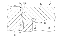
- FIG. FIG. 4 is a cross-sectional view showing a butting step in the method for manufacturing a joined body according to the present embodiment
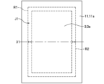
- FIG. 4 is a plan view showing the first region and the second region of the joined body according to the present embodiment
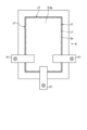
- FIG. 4 is a plan view showing a set movement route of the joined body according to the present embodiment
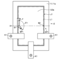
- FIG. 4 is a plan view showing a starting position of a first final bonding step in the method for manufacturing a bonded body according to the present embodiment
- FIG. 4 is a schematic diagram showing the insertion depth at the starting position of the rotary tool in the first main joining step of the method for manufacturing a joined body according to the present embodiment
- FIG. 4 is a cross-sectional view showing a first main bonding step of the method for manufacturing a bonded body according to the present embodiment
- FIG. 4 is a plan view showing the end position of the first main joining step in the method for manufacturing a joined body according to the present embodiment
- FIG. 4 is a schematic diagram showing the insertion depth at the end position of the rotating tool in the first main joining step of the method for manufacturing a joined body according to the present embodiment
- FIG. 4 is a plan view showing a second final bonding step of the method for manufacturing a bonded body according to the present embodiment
- FIG. 10 is a plan view showing the end position of the second final joining step of the method for manufacturing a joined body according to the present embodiment
- FIG. 11 is a plan view showing a first main joining step of a method for manufacturing a joined body according to a first modified example;
- FIG. 11 is a plan view showing a second main joining step of the method for manufacturing a joined body according to the first modified example;
- FIG. 11 is a plan view showing a first main joining step of a method for manufacturing a joined body according to a second modified example;
- FIG. 11 is a plan view showing a second main joining step of a method for manufacturing a joined body according to a second modified example;
- FIG. 11 is a plan view showing a method of manufacturing a joined body according to a third modified example;
- FIG. 11 is a plan view showing a method for manufacturing a joined body according to a fourth modified example;
- a joined body (liquid cooling jacket) 1 is composed of a jacket body (first metal member) 2 and a sealing body (second metal member) 3, as shown in FIG.
- the joined body 1 is a device that circulates a fluid inside to cool a heat generating element arranged therein.
- the jacket body 2 and the sealing body 3 are integrated by friction stir welding.
- the "front surface” in the following description means the surface opposite to the "back surface”.
- the jacket body (first metal member) 2 is mainly composed of a bottom portion 10 and a peripheral wall portion 11 .
- the jacket body 2 is not particularly limited as long as it is a metal that can be friction-stirred, but in this embodiment it is formed mainly of a first aluminum alloy.
- a first aluminum alloy for example, an aluminum alloy cast material such as JISH5302 ADC12 (Al-Si-Cu system) is used.
- the bottom part 10 is a rectangular plate-like member.
- the peripheral wall portion 11 is a wall portion that rises in a rectangular frame shape from the peripheral portion of the bottom portion 10 .
- a concave portion 13 is formed by the bottom portion 10 and the peripheral wall portion 11 .
- a peripheral wall stepped portion 12 is formed on the inner peripheral edge of the peripheral wall portion 11 .
- the peripheral wall step portion 12 includes a step bottom surface 12a and a step side surface (side surface) 12b that rises obliquely from the step bottom surface 12a. As shown in FIG. 2, the inclination angle ⁇ of the stepped side surface 12b may be set as appropriate. It has become.
- stepped side surface 12b may be perpendicular to the stepped bottom surface 12a.
- the jacket main body 2 of the present embodiment is integrally formed, for example, the peripheral wall portion 11 may be divided and joined by a sealing member to be integrated.
- the sealing body (second metal member) 3 is a plate-like member that seals the opening of the jacket body 2 .
- the sealing body 3 is not particularly limited as long as it is a metal that can be friction-stirred, but in this embodiment, it is formed mainly containing a second aluminum alloy.
- the second aluminum alloy is a material with a lower hardness than the first aluminum alloy.
- the second aluminum alloy is formed of an aluminum alloy wrought material such as JIS A1050, A1070, A1100, A6063, for example.
- a method for manufacturing a joined body according to this embodiment will be described.
- a preparation step, a butting step, and a final joining step are performed.
- the preparation process is a process of preparing the jacket main body 2 and the sealing body 3.
- the method of manufacturing the jacket body 2 and the sealing body 3 is not particularly limited, but the jacket body 2 is formed by die casting, for example.
- the sealing body 3 is formed by extrusion molding, for example.
- the butting step is, as shown in FIG. 2, a step of placing the sealing body 3 on the jacket body 2 and butting the side surfaces thereof.
- the side surface 3c of the sealing body 3 and the stepped side surface (side surface) 12b of the peripheral wall stepped portion 12 are butted to form the first butted portion J1. Since the stepped side surface 12b is inclined outward, a gap having a V-shaped cross section is formed in the first abutting portion J1.
- the first butting portion J1 is formed in a rectangular shape in a plan view along the periphery of the sealing body 3 . Further, the stepped bottom surface 12a of the peripheral wall stepped portion 12 and the rear surface 3b of the sealing body 3 are butted together to form a second butted portion J2.
- the plate thickness of the sealing body 3 may be appropriately set, but in this embodiment, it is larger than the height dimension of the stepped side surface 12b.
- a region of the first butted portion J1 on one side (upper side in FIG. 3) of the intermediate line X1 set on the sealing body 3 is defined as a first region R1.
- a region of the first butted portion J1 on the other side (lower side in FIG. 3) of the intermediate line X1 is defined as a second region R2.
- An intermediate line X1 is a line segment passing through the middle of the sealing body 3 in the longitudinal direction.
- the jacket body 2 and the sealing body 3 related to the second region R2 are immovably clamped with three clamps K1. .
- a “set movement route L1” (chain line) is set inside the first matching portion J1.
- the set movement route L1 is a movement route of the rotating tool F necessary for joining the first butted portion J1 in the main joining step described later.
- the stirring pin F2 of the rotary tool F is slightly brought into contact with the stepped side surface 12b, so the set movement route L1 is set to have a rectangular shape in plan view inside the side surface 3c.
- the main welding step is a step of friction stir welding the first butted portion J1 using a rotating tool F.
- the first main bonding step of bonding the first region R1 (see FIG. 3) of the first butted portion J1 and the second region R2 (see FIG. 3) of the first butted portion J1 are bonded.
- a second main bonding step is performed, respectively.
- the rotating tool F is composed of a connecting portion F1 and a stirring pin F2.
- the rotary tool F is made of tool steel, for example.
- the connecting portion F1 is a portion connected to a rotating shaft of a friction stirrer (not shown).
- the connecting portion F1 has a cylindrical shape and is formed with a screw hole (not shown) for fastening a bolt.
- the stirring pin F2 hangs down from the connecting portion F1 and is coaxial with the connecting portion F1.
- the agitating pin F2 tapers away from the connecting portion F1.
- a flat surface F3 is provided at the tip of the stirring pin F2.
- a spiral groove is engraved on the outer peripheral surface of the stirring pin F2.
- the spiral groove is formed counterclockwise from the proximal end toward the distal end.
- the spiral groove is formed counterclockwise when viewed from above when the spiral groove is traced from the proximal end to the distal end.
- the spiral groove When rotating the rotating tool F counterclockwise, it is preferable to form the spiral groove clockwise from the proximal end toward the distal end.
- the helical groove in this case is formed in a clockwise direction as viewed from above when the helical groove is traced from the proximal end to the distal end.
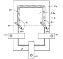
- the push-in section from the start position SP1 to the intermediate point S1, the main section from the intermediate point S1 to the intermediate point S2 on the set movement route L1, and from the intermediate point S2 Friction stir-stirring is continuously performed in three sections of the detachment section up to the end position EP1.
- the intermediate points S1 and S2 are set at positions where the intermediate line X1 and the set movement route L1 intersect.
- the start position SP1 is set at a position inside the set movement route L1 on the surface 3a of the sealing body 3. As shown in FIG.
- the angle ⁇ 1 formed by the line segment connecting the start position SP1 and the intermediate point S1 and the set movement route L1 is set to be an obtuse angle.
- the angle ⁇ 1 is not particularly limited as long as it is an obtuse angle, it is preferably 120° or more, more preferably 150° or more, still more preferably 170° or more, preferably less than 180°, more preferably 175° or less.
- the insertion hole provided at the start position SP1 is provided near the outer periphery of the sealing body 3 on the surface of the sealing body 3 .
- the rotational speed of the rotating tool F when performing friction stir welding may be appropriately set.
- the rotating tool F may be moved to the intermediate point S1 while gradually decreasing the rotational speed from a rotational speed higher than the speed.
- the small pressing force in the pushing step can be compensated for by the rotation speed, so friction stirring can be performed favorably.
- the friction stir welding of this section is performed as it is.
- the rotary tool F is moved so that the rotation axis C of the stirring pin F2 and the set movement route L1 overlap.
- the peripheral wall portion 11 of the jacket body 2 and the surface 3a of the sealing body 3 are separated from the connecting portion F1 of the rotating tool F, and only the stirring pin F2 is placed between the jacket body 2 and the surface 3a of the sealing body 3. It is set to be inserted into the sealing body 3 .
- the "predetermined depth" of the stirring pin F2 is set to such an extent that the flat surface F3 of the stirring pin F2 slightly contacts the stepped bottom surface 12a.
- the “predetermined depth” of the stirring pin F2 may be set as appropriate, for example, it may be set at a position that does not reach the bottom surface 12a of the step.
- the contact amount of the flat surface F3 of the stirring pin F2 with respect to the stepped bottom surface 12a is defined as an insertion amount D (not shown).
- the insertion amount D is set between 0 ⁇ D ⁇ 1.0 mm, preferably 0 ⁇ D ⁇ 0.0 mm. It is set between 85 mm, more preferably between 0 ⁇ D ⁇ 0.65 mm.
- the set movement route L1 is set so that the outer peripheral surface of the stirring pin F2 slightly contacts the stepped side surface 12b.
- the amount of contact of the outer peripheral surface of the stirring pin F2 with respect to the stepped side surface 12b is defined as an offset amount N.
- the offset amount N is set between 0 ⁇ N ⁇ 1.0 mm, preferably between 0 ⁇ N ⁇ 0.85 mm, and more preferably between 0 ⁇ N ⁇ 0.65 mm.
- the bonding strength of the first butted portion J1 will be low. Further, if the offset amount N between the outer peripheral surface of the stirring pin F2 and the stepped side surface 12b exceeds 1.0 mm, a large amount of the first aluminum alloy of the jacket body 2 may be mixed into the sealing body 3 side, resulting in poor bonding. There is Moreover, in this section, the rotation speed of the rotating tool F at the time of performing the friction stir welding of the first butt portion J1 may be appropriately set.
- the rotation speed of the rotating tool F when performing friction stir welding of the first butt portion J1 is preferably 5000 rpm or more, more preferably 7000 rpm or more, still more preferably 9000 rpm or more, and preferably 20000 rpm or less, more preferably 17000 rpm or less. , more preferably 15000 rpm or less.
- the rotation speed of the rotating tool F can be set according to, for example, the materials of the first aluminum alloy and the second aluminum alloy, the thickness of the sealing body 3, the insertion depth of the stirring pin F2, and the like.
- the rotation speed in the detachment section can be set to 10% or more and 50% or less.
- the rotation speed in the detachment section refers to the final rotation speed reached by the stirring pin F2 when moving the rotating tool F while gradually decreasing the rotational speed in the detachment section. In particular, it refers to the rotational speed reached when the stirring pin F2 is detached.
- the rotation speed in the detached section with respect to the rotation speed of the rotating tool F when performing friction stir welding of the first butt portion J1 is preferably 15% or more, more preferably 20% or more, and still more preferably 25% or more.
- the rotation speed of the rotating tool F may be set as appropriate, and may be set to, for example, 1000 rpm or more and 8000 rpm or less.
- the rotation speed of the rotating tool F in the detachment section is preferably 2000 rpm or more, more preferably 3000 rpm or more, still more preferably 4000 rpm or more, and preferably 7000 rpm or less, more preferably 6000 rpm or less, and still more preferably 5000 rpm or less.
- the end position EP1 is set on the peripheral wall end face 11a of the peripheral wall portion 11 outside the set movement route L1.
- the end position EP1 is set on the peripheral wall end surface 11a of the peripheral wall portion 11 at a position where the angle ⁇ 2 formed by the line segment connecting the end position EP1 and the intermediate point S2 and the set movement route L1 is an obtuse angle.
- a plasticized region W1 is formed in the movement locus of the rotating tool F. As shown in FIG.
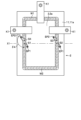
- the clamps K1 are temporarily released, and as shown in FIG. 10, the jacket main body 2 and the sealing body 3 related to the first region R1 (see FIG. 3) cannot be moved by the three clamps K1. clamp to
- the second main welding step is a step of performing friction stir welding on the first butted portion J1 of the second region R2 (see FIG. 3).
- the pushing-in section from the start position SP2 to the intermediate point S3, the main section from the intermediate point S3 to the intermediate point S4 on the set movement route L1, and from the intermediate point S4 Friction stir-stirring is continuously performed in three sections of the detachment section up to the end position EP2.
- the start position SP2 is set at a position inside the set movement route L1 on the surface 3a of the sealing body 3.
- the intermediate point S3 is set closer to the first region R1 (see FIG. 3) than the intermediate point S2 on the set travel route L1.
- the angle ⁇ 3 formed by the line segment connecting the start position SP2 and the intermediate point S3 and the set movement route L1 is set to be an obtuse angle.
- the end position EP2 is set on the peripheral wall end face 11a of the peripheral wall portion 11 outside the set movement route L1. That is, the end position EP2 is set at a position where the line segment connecting the end position EP2 and the intermediate point S4 on the peripheral wall end face 11a of the peripheral wall portion 11 forms an obtuse angle ⁇ 4 with the set movement route L1.
- a plasticized region W2 is formed in the movement locus of the rotating tool F. As shown in FIG. Through the steps described above, the joined body 1 is formed.
- the rotational speed of the rotating tool F may be set as appropriate, but if the rotational speed during the friction stir of the first abutting portion J1 is 100% in this section, the rotational speed in the detachment section should be 10% or more. , is preferably set to 50% or less. Also, in the detachment section, on the premise that the rotation speed is gradually lowered than in this section, the rotation speed when performing friction stir at the first butt portion J1 in this section is set to 5000 rpm or more and 20000 rpm or less, and the detachment It is preferable to set the rotation speed in the section to 1000 rpm or more and 8000 rpm or less.
- the rotation speed of the rotating tool F may be set as appropriate, but by setting it as described above, the above effects can be achieved more accurately.
- the second aluminum alloy mainly on the sealing body 3 side of the first abutting portion J1 is agitated and plastically fluidized by the frictional heat between the sealing body 3 and the stirring pin F2, and the stepped side surface 12b at the first abutting portion J1. and the side surface 3c of the sealing body 3 can be joined.
- the outer peripheral surface of the stirring pin F2 is kept in slight contact with the stepped side surface 12b of the jacket body 2, mixing of the first aluminum alloy from the jacket body 2 into the sealing body 3 can be minimized.
- the second aluminum alloy on the side of the sealing body 3 is friction-stirred at the first butted portion J1, so that a decrease in joint strength can be suppressed.
- the imbalance in the material resistance received by the stirring pin F2 between the one side and the other side with respect to the rotation axis C of the stirring pin F2 can be minimized.
- the plastic flow material is friction-stirred in a well-balanced manner, so that a decrease in bonding strength can be suppressed.
- the stirring pin F2 is moved until a predetermined depth is reached. By gradually pushing it in, it is possible to prevent the rotary tool F from stopping on the set movement route L1 and causing excessive frictional heat.
- the stirring pin F2 is gradually raised from a predetermined depth while moving the rotating tool F from the set movement route L1 to the end positions EP1 and EP2. It is possible to prevent the rotary tool F from stopping on the set moving route L1 and the frictional heat from becoming excessive.
- the first butt portion J1 and the second butt portion J2 can be reliably welded.
- the first aluminum alloy is mixed from the jacket body 2 into the sealing body 3. can be prevented as much as possible.
- the positions of the start positions SP1 and SP2 may be appropriately set.
- the moving speed of the rotating tool F does not decrease, and the transition to this section is made smoothly.
- the positions of the end positions EP1 and EP2 may be appropriately set.
- the moving speed of the rotating tool F does not decrease, and the transition to the detachment section is smooth.
- the rotating direction and advancing direction of the rotating tool F may be appropriately set.
- the direction of rotation and the direction of movement of the rotary tool F were set so that the side of the sealing body 3 was the side of the flow.
- the stirring action by the stirring pin F2 around the first butt portion J1 is enhanced, and the temperature rise at the first butt portion J1 can be expected.
- the stepped side surface 12b and the side surface 3c of the sealing body 3 can be joined more reliably.
- the shear side means the side where the relative speed of the outer circumference of the rotating tool with respect to the part to be welded is the value obtained by adding the magnitude of the tangential speed at the outer circumference of the rotating tool and the magnitude of the moving speed.
- the flow side refers to the side where the relative speed of the rotating tool with respect to the parts to be welded becomes low due to the rotation of the rotating tool in the direction opposite to the moving direction of the rotating tool.
- the first aluminum alloy of the jacket main body 2 is a material with higher hardness than the second aluminum alloy of the sealing body 3 . Thereby, the durability of the joined body 1 can be enhanced.
- the first aluminum alloy of the jacket main body 2 is a cast aluminum alloy material
- the second aluminum alloy of the sealing body 3 is a wrought aluminum alloy material.
- the rotary tool F and the clamp K1 interfere with each other during the main joining process, which complicates the work.
- the clamping position and the friction stir welding position are separately performed in the first main welding process and the second main welding process, so that the friction stir operation can be performed efficiently.
- the entire circumference of the first butt part J1 can be friction stir welded in the first main joining process and the second main joining process, so the airtightness and watertightness of the joined body can be improved.
- the ends of the plasticized region W1 formed by the first main bonding process and the plasticized region W2 formed by the second main bonding process overlap each other on the set movement route L1, the can improve airtightness and watertightness.
- the agitation pin F2 can be uniformly brought into contact with the stepped side surface 12b over the entire height direction. can be done. As a result, friction stir welding can be performed in a well-balanced manner.
- friction stir is performed with the base end side of the stir pin F2 of the rotary tool F exposed, so the load acting on the friction stir device can be reduced.
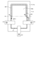
- start positions SP11 and SP12 are set on the set movement route L1, as shown in FIGS.
- the intermediate point S4 of the second main joining step is set on the first region R1 (see FIG. 3) side of the start position SP11 on the set movement route L1.
- the push-in section from the start position SP11 to the intermediate point S1, the main section from the intermediate point S1 to the intermediate point S2 on the set movement route L1, and the end from the intermediate point S2 Friction stir is continuously performed on the three sections of the separation section up to the position EP1.
- a plasticized region W11 is formed in the movement locus of the rotating tool F.
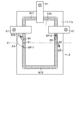
- the push-in section from the start position SP12 to the intermediate point S3 the main section from the intermediate point S3 to the intermediate point S4 on the set movement route L1, the intermediate point S4 to the end position EP2.
- the rotating tool F is moved from the intermediate point S1 to the intermediate point S4 so that the stirring pin F2 passes through the starting position SP11.
- a plasticized region W12 is formed in the movement locus of the rotating tool F. As shown in FIG. In this manner, in the main section of the second main bonding step, the insertion hole formed at the start position SP11 can be filled with the plasticized region W12.
- the rotational speed of the rotating tool F when performing friction stir welding may be set as appropriate.
- the rotating tool may be moved to the intermediate points S1 and S3 while gradually decreasing the rotating speed from a rotating speed higher than that of the rotating tool F at .
- the stirring pin F2 reaches the intermediate points S2 and S4
- the rotational speed is changed toward the rotational speed of the rotating tool F in this section so that it reaches the rotational speed of the rotating tool F in this section. is preferred.
- the insertion hole provided at the start position SP11 on the set movement route L1 can be filled. Therefore, since no insertion hole remains in the jacket body (first metal member) 2 and the sealing body (second metal member) 3, repair of the insertion hole becomes unnecessary, and pre-processing for repairing the insertion hole is performed after friction stir. It is possible to install the electronic component on the second metal member without any trouble. Also, compared to the embodiment, the plasticized region formed on the second metal member can be made smaller. Therefore, it is possible to further increase the degree of freedom in designing the joined body in which the first metal member and the second metal member are joined by friction stir, and to further improve the productivity.
- start positions SP21 and SP22 are set on the peripheral wall end face 11a of the peripheral wall portion 11, as shown in FIGS.
- the start positions SP21 and SP22 are set at positions outside the set movement route L1 on the peripheral wall end surface 11a of the peripheral wall portion 11 .
- the angles ⁇ 21 and ⁇ 22 formed between the line segment connecting the start positions SP21 and SP22 and the intermediate points S1 and S2 and the set movement route L1 are set to obtuse angles.
- the push-in section from the start position SP21 to the intermediate point S1, the main section from the intermediate point S1 to the intermediate point S2 on the set movement route L1, and the end from the intermediate point S2 Friction stir is continuously performed on the three sections of the separation section up to the position EP1.
- a plasticized region W21 is formed in the movement trajectory of the rotating tool F.
- a plasticized region W22 is formed in the movement locus of the rotating tool F. As shown in FIG.
- the stirring pin F2 in the pushing section of the main joining step, is moved so as to reach a preset "predetermined depth" from the start positions SP21 and SP22 to at least the intermediate points S1 and S2. Push in gradually.
- the rotating tool F is gradually lowered while being moved along the set movement route L1 without remaining in one place.
- the rotation speed of the rotating tool F in the push-in section may be gradually increased from a rotation speed lower than that in this section to move the rotating tool to the intermediate point S1. For example, if the rotation speed of the rotating tool F when performing friction stir welding of the first butt portion J1 in this section is 100%, the rotation speed in the pushing section can be set to 10% or more and 50% or less. .
- the rotation speed in the push-in section with respect to the rotation speed of the rotating tool F when performing friction stir welding of the first butt portion J1 is preferably 15% or more, more preferably 20% or more, and still more preferably 25% or more. is 45% or less, more preferably 40% or less, still more preferably 35% or less. Also, in the push-in section, the rotation speed of the rotating tool F may be set as appropriate, and can be set to, for example, 1000 rpm or more and 8000 rpm or less.
- the rotation speed of the rotary tool F in the pushing section is preferably 2000 rpm or more, more preferably 3000 rpm or more, still more preferably 4000 rpm or more, and preferably 7000 rpm or less, more preferably 6000 rpm or less, still more preferably 5000 rpm or less.
- the insertion hole can be formed in the jacket main body 2 (first metal member) side, and the insertion hole is not formed in the sealing body (second metal member) 3 side. It becomes unnecessary to repair the insertion hole in the member, and it becomes possible to install the electronic component on the second metal member without performing pre-processing for repairing the insertion hole after friction stir.
- the plasticized region formed on the sealing body 3 can be made smaller. Therefore, it is possible to further increase the degree of freedom in designing the joined body in which the first metal member and the second metal member are joined by friction stir, and to further improve the productivity.
- the friction stir is performed while clamping in two steps, but the friction stir may be performed in one step, or may be performed in three or more steps while clamping.
- the third modified example differs from the embodiment in that the main bonding step is performed once instead of being divided into two steps.
- the description will focus on the parts that are different from the embodiment.
- the pushing section from the starting position SP1 to the intermediate point S1 and the set movement route L1 from the intermediate point S1 to the sealing body 3 are circled.
- Friction stir is continuously performed in three sections, namely, the main section from the intermediate point S4 to the intermediate point S4 and the separation section from the intermediate point S4 to the end position EP2.
- a plasticized region W31 is formed in the movement locus of the rotating tool F.
- the jacket body 2 and the sealing body 3 are clamped at a plurality of locations while friction stirring is performed, the clamping at the location where the rotating tool F approaches is once released, and the clamping is performed again after the rotating tool F has passed.
- the fourth modified example differs from the embodiment in that the starting position SP11 in the main bonding step is different from the embodiment, and the main bonding step is performed once.
- the description will focus on the parts that are different from the embodiment.
- the start position SP11 is set on the set movement route L1.
- An intermediate point S4 of the first main joining step is set on the first region R1 (see FIG. 3) side of the start position SP11 on the set movement route L1.
- the pressing section from the starting position SP11 to the intermediate point S1 and the set movement route L1 from the intermediate point S1 to the sealing body 3 are circumnavigated.
- Friction stir is continuously performed in three sections, namely, the main section from the intermediate point S4 to the intermediate point S4 and the separation section from the intermediate point S4 to the end position EP2.
- the rotary tool F is moved from the intermediate point S1 to the intermediate point S4 so that the stirring pin F2 passes through the starting position SP11.
- a plasticized region W41 is formed in the movement locus of the rotating tool F.
- the insertion hole formed at the start position SP11 can be filled with the plasticized region W41.
- the jacket body 2 and the sealing body 3 are clamped at a plurality of locations while friction stirring is performed, the clamping at the location where the rotating tool F approaches is once released, and the clamping is performed again after the rotating tool F has passed.
- the rotational speed of the rotating tool F when performing friction stir welding may be set as appropriate.
- the rotating tool F may be moved to the intermediate point S1 while gradually decreasing the rotating speed from a higher rotating speed than the rotating speed of the tool F. At this time, it is preferable to change the rotation speed toward the rotation speed of the rotating tool F in this section so that the rotation speed of the rotating tool F in this section is reached when the stirring pin F2 reaches the intermediate point S1. .
- the insertion hole provided at the start position SP11 on the set movement route L1 can be filled. Therefore, since it does not remain on the side of the sealing body (second metal member) 3, it is unnecessary to repair the insertion hole with the second metal member, and the second metal can be removed without pre-processing for repairing the insertion hole after friction stir. It becomes possible to install electronic components on the member.
- the plasticized region formed on the sealing body 3 can be made smaller. Therefore, it is possible to further increase the degree of freedom in designing the joined body in which the first metal member and the second metal member are joined by friction stir, and to further improve the productivity.
- the rotating tool F is moved so that the stirring pin F2 passes through the starting position SP11 before the rotating tool F is separated from the jacket body (first metal member) 2 at the end position EP2.
- the insertion hole provided only at the start position SP11 can be filled. Therefore, since no insertion hole remains on the set movement route L1, the degree of freedom in design can be further increased, and productivity can be further improved.
- a temporary bonding process for temporarily bonding the jacket main body 2 and the sealing body 3 may be performed before performing the main bonding process.
- opening between the jacket body 2 and the sealing body 3 can be prevented during the main joining process.
- the temporary joining step may be performed by friction stir using a rotating tool for temporary joining, or may be performed by welding.
- the movement route may be set so that the movement locus of the rotating tool F draws a curved line (for example, an arc) in a plan view. As a result, it is possible to smoothly transition from the push-in section to the main section or from the main section to the detachment section.
- the case where only the stirring pin F2 is inserted into the jacket main body 2 and the sealing body 3 using the rotary tool F to perform the friction stir welding has been exemplified and explained.
- the rotary tool and friction stir welding are not limited to this.
- a rotary tool having a shoulder and a stir pin hanging down from the shoulder is used to insert the stir pin into the jacket body 2 and the sealing body 3, Friction stir welding may be performed while the shoulder is in contact with the peripheral wall portion 11 of the jacket body 2 and the surface 3 a of the sealing body 3 .
Landscapes
- Engineering & Computer Science (AREA)
- Mechanical Engineering (AREA)
- Pressure Welding/Diffusion-Bonding (AREA)
Abstract
Description
本実施形態に係る接合体(液冷ジャケット)1は、図1に示すように、ジャケット本体(第一金属部材)2と封止体(第二金属部材)3とで構成されている。接合体1は、内部に流体を流通させて、配置される発熱体を冷却する機器である。ジャケット本体2と封止体3とは摩擦攪拌接合で一体化される。以下の説明における「表面」とは、「裏面」の反対側の面を意味する。
また、離脱区間において、本区間よりも回転速度を徐々に下げることを前提としつつ、本区間において第一突合せ部J1の摩擦攪拌を行う際の回転速度を5000rpm以上、20000rpm以下に設定し、離脱区間における回転速度を1000rpm以上、8000rpm以下に設定することが好ましい。
同様に、第一本接合工程及び第二本接合工程の離脱区間では、設定移動ルートL1から終了位置EP1,EP2まで回転ツールFを移動させつつ所定の深さから攪拌ピンF2を徐々に上昇させて離脱させることにより、設定移動ルートL1上で回転ツールFが停止して摩擦熱が過大になるのを防ぐことができる。
第一変形例では、図12、図13に示すように、本接合工程における開始位置SP1,SP2の位置が実施形態と相違する。第一変形例では、実施形態と相違する部分を中心に説明する。
第二変形例では、図14、図15に示すように、本接合工程における開始位置SP21,SP22の位置が実施形態と相違する。第二変形例では、実施形態と相違する部分を中心に説明する。
本実施形態では、二回に分けてクランプしつつ摩擦攪拌を行ったが、一回で行ってもよいし、三回以上に分けてクランプしつつ摩擦攪拌を行ってもよい。第三変形例では、図16に示すように、二回に分けずに一回で本接合工程を行う点で実施形態と相違する。第三変形例では、実施形態と相違する部分を中心に説明する。
第四変形例では、図17に示すように、本接合工程における開始位置SP11の位置が実施形態と相違するとともに、一回で本接合工程を行う点で実施形態と相違する。第四変形例では、実施形態と相違する部分を中心に説明する。
以上本発明の実施形態及び変形例について説明したが、本発明の趣旨に反しない範囲において適宜設計変更が可能である。
例えば、開始位置SP1,SP2では、回転ツールFを移動させながら徐々に押し込んだが、開始位置SP1,SP2で所定の位置まで押し込んだ後、回転ツールFを移動させてもよい。また、終了位置EP1,EP2では、回転ツールFを移動させながら徐々に上昇させた(離脱させた)が、所定の深さ(一定の深さ)で終了位置EP1,EP2まで回転ツールFを移動させた後、終了位置EP1,EP2で鉛直方向に回転ツールFを上昇させて離脱させてもよい。
2 ジャケット本体(第一金属部材)
3 封止体(第二金属部材)
F 回転ツール
F2 攪拌ピン
F3 平坦面
J1 第一突合せ部
J2 第二突合せ部
EP1 終了位置
EP2 終了位置
W 塑性化領域
Claims (8)
- 第一金属部材と第二金属部材とを摩擦攪拌で接合する接合体の製造方法であって、
前記第一金属部材は第一アルミニウム合金で形成されており、前記第二金属部材は第二アルミニウム合金で形成されており、前記第一アルミニウム合金は前記第二アルミニウム合金よりも硬度が高い材種であり、
摩擦攪拌で用いる回転ツールは、攪拌ピンを備え、
前記第一金属部材の側面と前記第二金属部材の側面とを突き合わせて突合せ部を形成する突合せ工程と、
回転する前記回転ツールの前記攪拌ピンを前記第二金属部材に挿入し、前記攪拌ピンの外周面を前記第一金属部材にわずかに接触させた状態で、前記第二金属部材の側面よりも内側に設定された設定移動ルートに沿って所定の深さで前記突合せ部を摩擦攪拌接合する本接合工程と、を含み、
前記本接合工程において、前記設定移動ルートよりも外側の前記第一金属部材に終了位置を設定し、前記突合せ部に対する摩擦攪拌接合の後、前記回転ツールを前記終了位置に移動させつつ、前記終了位置で前記第一金属部材から前記回転ツールを離脱させる離脱区間を有し、
前記本接合工程では、所定の回転速度で前記攪拌ピンを回転させて前記突合せ部の摩擦攪拌接合を行い、
前記離脱区間において、前記所定の回転速度よりも徐々に回転速度を下げながら前記回転ツールを前記終了位置に向けて移動させて、前記回転ツールを第一金属部材から離脱させる、
ことを特徴とする接合体の製造方法。 - 前記本接合工程において、前記突合せ部の摩擦攪拌接合を行う際の回転速度を100%とした場合、前記離脱区間における最終的な回転速度が10%以上、50%以下である、
請求項1に記載の接合体の製造方法。 - 前記本接合工程において、前記突合せ部の摩擦攪拌接合を行う際の回転速度が5000rpm以上、20000rpm以下であり、
前記離脱区間における最終的な回転速度が1000rpm以上、8000rpm以下である、
請求項1に記載の接合体の製造方法。 - 前記第一金属部材をダイキャストで形成する準備工程をさらに備える、
請求項1に記載の接合体の製造方法。 - 前記本接合工程において、前記設定移動ルート上に開始位置を設定し、前記突合せ部に対する摩擦攪拌接合の前に、前記攪拌ピンを前記開始位置に挿入して、前記回転ツールを前記開始位置から移動させつつ下降させる押入区間を有し、
前記本接合工程において、前記終了位置で前記第一金属部材から前記回転ツールを離脱させる前に、前記攪拌ピンが前記開始位置を通過するように前記回転ツールを移動させて摩擦攪拌接合を行う、請求項1に記載の接合体の製造方法。 - 前記本接合工程において、前記設定移動ルート上に開始位置を設定し、前記突合せ部に対する摩擦攪拌接合の前に、前記攪拌ピンを前記開始位置に挿入して、前記回転ツールを前記開始位置から移動させつつ下降させる押入区間を有し、
前記押入区間において、前記所定の回転速度よりも高い回転速度から徐々に回転速度を下げながら、前記設定移動ルート上に設定された中間点に向けて前記回転ツールを移動させつつ下降させる、
請求項1に記載の接合体の製造方法。 - 前記本接合工程において、前記設定移動ルートよりも内側の前記第二金属部材に開始位置を設定し、前記突合せ部に対する摩擦攪拌接合の前に、前記攪拌ピンを前記開始位置に挿入して、前記回転ツールを前記開始位置から移動させつつ下降させる押入区間を有し、
前記押入区間において、前記所定の回転速度よりも高い回転速度から徐々に回転速度を下げながら前記回転ツールを移動させつつ下降させる、
請求項1に記載の接合体の製造方法。 - 前記本接合工程において、前記設定移動ルートよりも外側の前記第一金属部材に開始位置を設定し、前記突合せ部に対する摩擦攪拌接合の前に、前記攪拌ピンを前記開始位置に挿入して、前記回転ツールを前記開始位置から移動させつつ下降させる押入区間を有し、
前記押入区間において、前記所定の回転速度よりも低い回転速度から徐々に回転速度を上げながら前記回転ツールを移動させつつ下降させる、
請求項1に記載の接合体の製造方法。
Priority Applications (3)
| Application Number | Priority Date | Filing Date | Title |
|---|---|---|---|
| CN202280071236.7A CN118139714A (zh) | 2021-11-05 | 2022-10-04 | 接合体的制造方法 |
| EP22889715.3A EP4424451A4 (en) | 2021-11-05 | 2022-10-04 | METHOD FOR MANUFACTURING AN ASSEMBLED BODY |
| US18/706,708 US20250041965A1 (en) | 2021-11-05 | 2022-10-04 | Method for manufacturing joined body |
Applications Claiming Priority (2)
| Application Number | Priority Date | Filing Date | Title |
|---|---|---|---|
| JP2021-180854 | 2021-11-05 | ||
| JP2021180854A JP7775642B2 (ja) | 2021-11-05 | 2021-11-05 | 接合体の製造方法 |
Publications (1)
| Publication Number | Publication Date |
|---|---|
| WO2023079891A1 true WO2023079891A1 (ja) | 2023-05-11 |
Family
ID=86241456
Family Applications (1)
| Application Number | Title | Priority Date | Filing Date |
|---|---|---|---|
| PCT/JP2022/037101 Ceased WO2023079891A1 (ja) | 2021-11-05 | 2022-10-04 | 接合体の製造方法 |
Country Status (6)
| Country | Link |
|---|---|
| US (1) | US20250041965A1 (ja) |
| EP (1) | EP4424451A4 (ja) |
| JP (1) | JP7775642B2 (ja) |
| CN (1) | CN118139714A (ja) |
| TW (1) | TW202327771A (ja) |
| WO (1) | WO2023079891A1 (ja) |
Families Citing this family (2)
| Publication number | Priority date | Publication date | Assignee | Title |
|---|---|---|---|---|
| JP2025110529A (ja) * | 2024-01-16 | 2025-07-29 | 日本軽金属株式会社 | 接合体の製造方法 |
| JP2025110528A (ja) * | 2024-01-16 | 2025-07-29 | 日本軽金属株式会社 | 接合体の製造方法 |
Citations (6)
| Publication number | Priority date | Publication date | Assignee | Title |
|---|---|---|---|---|
| JP2001321966A (ja) * | 2000-03-06 | 2001-11-20 | Hitachi Ltd | 摩擦攪拌接合方法 |
| JP2003048082A (ja) * | 2001-07-30 | 2003-02-18 | Kawasaki Heavy Ind Ltd | 摩擦攪拌接合装置 |
| JP2020011271A (ja) | 2018-07-19 | 2020-01-23 | 日本軽金属株式会社 | 液冷ジャケットの製造方法 |
| JP2020131263A (ja) | 2019-02-22 | 2020-08-31 | 日本軽金属株式会社 | 液冷ジャケットの製造方法 |
| JP2020175396A (ja) | 2019-04-15 | 2020-10-29 | 日本軽金属株式会社 | 液冷ジャケットの製造方法 |
| JP2021112757A (ja) * | 2020-01-16 | 2021-08-05 | 日本軽金属株式会社 | 液冷ジャケットの製造方法 |
Family Cites Families (12)
| Publication number | Priority date | Publication date | Assignee | Title |
|---|---|---|---|---|
| US6913186B2 (en) * | 2003-09-11 | 2005-07-05 | The Boeing Company | Apparatus and method for friction stir welding with a variable speed pin |
| US7416102B1 (en) * | 2004-10-22 | 2008-08-26 | Edison Welding Institute, Inc. | Method of friction stir welding and multi-section faced shoulderless retractable variable penetration friction stir welding tool for same |
| US7703654B2 (en) * | 2004-11-17 | 2010-04-27 | The Boeing Company | Counter-rotating spindle for friction stir welding |
| US8281977B2 (en) * | 2006-10-02 | 2012-10-09 | Nippon Light Metal Company, Ltd. | Joining method and friction stir welding method |
| JP5262822B2 (ja) * | 2009-02-23 | 2013-08-14 | 日本軽金属株式会社 | 液冷ジャケットの製造方法 |
| JP5631162B2 (ja) * | 2010-11-16 | 2014-11-26 | カルソニックカンセイ株式会社 | 摩擦攪拌接合方法 |
| JP6372516B2 (ja) * | 2015-08-26 | 2018-08-15 | 日本軽金属株式会社 | 液冷ジャケットの製造方法及び液冷ジャケット |
| CN110300636B (zh) * | 2017-04-18 | 2021-08-03 | 日本轻金属株式会社 | 液冷套的制造方法 |
| JP6885285B2 (ja) * | 2017-09-28 | 2021-06-09 | 日本軽金属株式会社 | 液冷ジャケットの製造方法 |
| CN112041111B (zh) * | 2018-07-19 | 2022-03-08 | 日本轻金属株式会社 | 液冷套的制造方法 |
| EP3854512A4 (en) * | 2018-09-18 | 2022-06-22 | Nippon Light Metal Company, Ltd. | LIQUID COOLING JACKET MANUFACTURING METHOD |
| WO2020170488A1 (ja) * | 2019-02-22 | 2020-08-27 | 日本軽金属株式会社 | 液冷ジャケットの製造方法 |
-
2021
- 2021-11-05 JP JP2021180854A patent/JP7775642B2/ja active Active
-
2022
- 2022-10-04 EP EP22889715.3A patent/EP4424451A4/en active Pending
- 2022-10-04 US US18/706,708 patent/US20250041965A1/en active Pending
- 2022-10-04 CN CN202280071236.7A patent/CN118139714A/zh active Pending
- 2022-10-04 WO PCT/JP2022/037101 patent/WO2023079891A1/ja not_active Ceased
- 2022-10-18 TW TW111139397A patent/TW202327771A/zh unknown
Patent Citations (6)
| Publication number | Priority date | Publication date | Assignee | Title |
|---|---|---|---|---|
| JP2001321966A (ja) * | 2000-03-06 | 2001-11-20 | Hitachi Ltd | 摩擦攪拌接合方法 |
| JP2003048082A (ja) * | 2001-07-30 | 2003-02-18 | Kawasaki Heavy Ind Ltd | 摩擦攪拌接合装置 |
| JP2020011271A (ja) | 2018-07-19 | 2020-01-23 | 日本軽金属株式会社 | 液冷ジャケットの製造方法 |
| JP2020131263A (ja) | 2019-02-22 | 2020-08-31 | 日本軽金属株式会社 | 液冷ジャケットの製造方法 |
| JP2020175396A (ja) | 2019-04-15 | 2020-10-29 | 日本軽金属株式会社 | 液冷ジャケットの製造方法 |
| JP2021112757A (ja) * | 2020-01-16 | 2021-08-05 | 日本軽金属株式会社 | 液冷ジャケットの製造方法 |
Non-Patent Citations (1)
| Title |
|---|
| See also references of EP4424451A4 |
Also Published As
| Publication number | Publication date |
|---|---|
| US20250041965A1 (en) | 2025-02-06 |
| TW202327771A (zh) | 2023-07-16 |
| EP4424451A1 (en) | 2024-09-04 |
| CN118139714A (zh) | 2024-06-04 |
| JP2023069179A (ja) | 2023-05-18 |
| JP7775642B2 (ja) | 2025-11-26 |
| EP4424451A4 (en) | 2026-04-15 |
Similar Documents
| Publication | Publication Date | Title |
|---|---|---|
| JP6766956B2 (ja) | 液冷ジャケットの製造方法 | |
| CN103817428B (zh) | 接合方法 | |
| CN112041111B (zh) | 液冷套的制造方法 | |
| WO2019193779A1 (ja) | 液冷ジャケットの製造方法 | |
| WO2019193778A1 (ja) | 液冷ジャケットの製造方法 | |
| JP2023069179A (ja) | 接合体の製造方法 | |
| JP7003861B2 (ja) | 液冷ジャケットの製造方法 | |
| WO2020158081A1 (ja) | 接合方法 | |
| JP7003862B2 (ja) | 液冷ジャケットの製造方法 | |
| JP7020562B2 (ja) | 液冷ジャケットの製造方法 | |
| CN111093880B (zh) | 液冷套的制造方法 | |
| JP6943139B2 (ja) | 液冷ジャケットの製造方法 | |
| JP6943140B2 (ja) | 液冷ジャケットの製造方法 | |
| JP2020175396A (ja) | 液冷ジャケットの製造方法 | |
| JP6927134B2 (ja) | 液冷ジャケットの製造方法 | |
| WO2020170488A1 (ja) | 液冷ジャケットの製造方法 | |
| JP2019155415A (ja) | 液冷ジャケットの製造方法 | |
| JP7272465B2 (ja) | 液冷ジャケットの製造方法 | |
| JP2020175395A (ja) | 液冷ジャケットの製造方法 | |
| JP2019155414A (ja) | 液冷ジャケットの製造方法 | |
| WO2019202754A1 (ja) | 液冷ジャケットの製造方法 | |
| JP2018176207A (ja) | 液冷ジャケットの製造方法 | |
| WO2020213185A1 (ja) | 液冷ジャケットの製造方法 | |
| JP2019202320A (ja) | 液冷ジャケットの製造方法 | |
| JP2019188413A (ja) | 液冷ジャケットの製造方法 |
Legal Events
| Date | Code | Title | Description |
|---|---|---|---|
| 121 | Ep: the epo has been informed by wipo that ep was designated in this application |
Ref document number: 22889715 Country of ref document: EP Kind code of ref document: A1 |
|
| WWE | Wipo information: entry into national phase |
Ref document number: 202280071236.7 Country of ref document: CN |
|
| WWE | Wipo information: entry into national phase |
Ref document number: 18706708 Country of ref document: US |
|
| WWE | Wipo information: entry into national phase |
Ref document number: 2022889715 Country of ref document: EP |
|
| ENP | Entry into the national phase |
Ref document number: 2022889715 Country of ref document: EP Effective date: 20240528 |