WO2023080114A1 - 作業機械 - Google Patents
作業機械 Download PDFInfo
- Publication number
- WO2023080114A1 WO2023080114A1 PCT/JP2022/040739 JP2022040739W WO2023080114A1 WO 2023080114 A1 WO2023080114 A1 WO 2023080114A1 JP 2022040739 W JP2022040739 W JP 2022040739W WO 2023080114 A1 WO2023080114 A1 WO 2023080114A1
- Authority
- WO
- WIPO (PCT)
- Prior art keywords
- straight line
- travel
- predicted
- area
- height
- Prior art date
- Legal status (The legal status is an assumption and is not a legal conclusion. Google has not performed a legal analysis and makes no representation as to the accuracy of the status listed.)
- Ceased
Links
Images



Classifications
-
- E—FIXED CONSTRUCTIONS
- E02—HYDRAULIC ENGINEERING; FOUNDATIONS; SOIL SHIFTING
- E02F—DREDGING; SOIL-SHIFTING
- E02F9/00—Component parts of dredgers or soil-shifting machines, not restricted to one of the kinds covered by groups E02F3/00 - E02F7/00
- E02F9/26—Indicating devices
-
- E—FIXED CONSTRUCTIONS
- E02—HYDRAULIC ENGINEERING; FOUNDATIONS; SOIL SHIFTING
- E02F—DREDGING; SOIL-SHIFTING
- E02F9/00—Component parts of dredgers or soil-shifting machines, not restricted to one of the kinds covered by groups E02F3/00 - E02F7/00
- E02F9/20—Drives; Control devices
- E02F9/2025—Particular purposes of control systems not otherwise provided for
- E02F9/205—Remotely operated machines, e.g. unmanned vehicles
-
- E—FIXED CONSTRUCTIONS
- E02—HYDRAULIC ENGINEERING; FOUNDATIONS; SOIL SHIFTING
- E02F—DREDGING; SOIL-SHIFTING
- E02F9/00—Component parts of dredgers or soil-shifting machines, not restricted to one of the kinds covered by groups E02F3/00 - E02F7/00
- E02F9/20—Drives; Control devices
- E02F9/2058—Electric or electro-mechanical or mechanical control devices of vehicle sub-units
- E02F9/2083—Control of vehicle braking systems
-
- E—FIXED CONSTRUCTIONS
- E02—HYDRAULIC ENGINEERING; FOUNDATIONS; SOIL SHIFTING
- E02F—DREDGING; SOIL-SHIFTING
- E02F9/00—Component parts of dredgers or soil-shifting machines, not restricted to one of the kinds covered by groups E02F3/00 - E02F7/00
- E02F9/20—Drives; Control devices
- E02F9/2058—Electric or electro-mechanical or mechanical control devices of vehicle sub-units
- E02F9/2087—Control of vehicle steering
-
- E—FIXED CONSTRUCTIONS
- E02—HYDRAULIC ENGINEERING; FOUNDATIONS; SOIL SHIFTING
- E02F—DREDGING; SOIL-SHIFTING
- E02F9/00—Component parts of dredgers or soil-shifting machines, not restricted to one of the kinds covered by groups E02F3/00 - E02F7/00
- E02F9/24—Safety devices, e.g. for preventing overload
-
- E—FIXED CONSTRUCTIONS
- E02—HYDRAULIC ENGINEERING; FOUNDATIONS; SOIL SHIFTING
- E02F—DREDGING; SOIL-SHIFTING
- E02F9/00—Component parts of dredgers or soil-shifting machines, not restricted to one of the kinds covered by groups E02F3/00 - E02F7/00
- E02F9/26—Indicating devices
- E02F9/261—Surveying the work-site to be treated
-
- E—FIXED CONSTRUCTIONS
- E02—HYDRAULIC ENGINEERING; FOUNDATIONS; SOIL SHIFTING
- E02F—DREDGING; SOIL-SHIFTING
- E02F9/00—Component parts of dredgers or soil-shifting machines, not restricted to one of the kinds covered by groups E02F3/00 - E02F7/00
- E02F9/26—Indicating devices
- E02F9/261—Surveying the work-site to be treated
- E02F9/262—Surveying the work-site to be treated with follow-up actions to control the work tool, e.g. controller
-
- E—FIXED CONSTRUCTIONS
- E02—HYDRAULIC ENGINEERING; FOUNDATIONS; SOIL SHIFTING
- E02F—DREDGING; SOIL-SHIFTING
- E02F3/00—Dredgers; Soil-shifting machines
- E02F3/04—Dredgers; Soil-shifting machines mechanically-driven
- E02F3/28—Dredgers; Soil-shifting machines mechanically-driven with digging tools mounted on a dipper- or bucket-arm, i.e. there is either one arm or a pair of arms, e.g. dippers, buckets
- E02F3/36—Component parts
- E02F3/42—Drives for dippers, buckets, dipper-arms or bucket-arms
- E02F3/43—Control of dipper or bucket position; Control of sequence of drive operations
- E02F3/435—Control of dipper or bucket position; Control of sequence of drive operations for dipper-arms, backhoes or the like
Definitions
- the present invention relates to working machines such as hydraulic excavators.
- Patent Document 1 As a technique for maintaining the vehicle body stability of working machines, for example, the hydraulic excavator disclosed in Patent Document 1 below is being studied. That is, a distance sensor for measuring the distance to the ground vertically below is provided in the front device of the hydraulic excavator, and the height of the point located vertically below the distance sensor is subtracted from the height of the ground contact surface of the undercarriage. A height difference is obtained, and when the obtained height difference is larger than a threshold value, travel of the hydraulic excavator is restricted. By doing so, it is attempted to maintain the stability of the vehicle body.
- the distance measuring sensor is rotatably attached to the front device so as to face vertically downward regardless of the orientation of the front device. It vibrates in the rotation direction of the range sensor. There is a problem that noise is generated due to such rotational vibration, making it difficult to accurately measure the distance. In order to accurately measure the distance, it is conceivable that the operation of the front device is decelerated or stopped, but decelerating or stopping the front device affects the productivity of the work machine. Therefore, the hydraulic excavator described in Patent Document 1 has room for improvement.
- the present invention was made to solve such technical problems, and aims to provide a work machine that can maintain the stability of the vehicle body and suppress the decrease in productivity due to the instability of the vehicle body.
- a working machine comprises a lower traveling body having a crawler belt, and an upper revolving body rotatably provided on the lower traveling body, wherein at least one revolving body is attached to the upper revolving body.
- a turning angle sensor for detecting a relative turning angle between the upper turning body and the lower traveling body; a notification device for notifying an operator of the working machine of information; and the lower traveling body and the notification device. and an angle corresponding to the maximum climbing angle of the work machine with respect to the traveling plane of the crawler belt while passing through a predicted traveling point at a certain distance from the crawler belt on the traveling plane of the crawler belt.
- the control device calculates the distance measured by the distance measuring sensor and the ground area.
- the height of the predicted travel area is calculated based on the detection result of the turning angle sensor, and the height difference between the calculated height of the predicted travel area and the height of the traveling plane of the crawler belt is equal to or greater than a preset threshold value. It is characterized in that the notification device is activated when it is determined that the height difference is equal to or greater than the threshold value.
- the first straight line is a straight line that passes through the predicted traveling point at a certain distance from the crawler belt on the traveling plane of the crawler belt and has an angle corresponding to the maximum climbing angle of the working machine with respect to the traveling plane of the crawler belt.
- the distance measuring sensor is mounted on the upper revolving body so as to be positioned above the first straight line, where the straight line connecting the mounting position of the distance measuring sensor and the predicted travel point is defined as a second straight line. Measure the distance from to the ground on the second straight line. In this way, since the distance measuring sensor can measure the distance at an angle larger than the maximum climbing angle, it is possible to reliably detect a step whose difference in height exceeds the maximum climbing angle.
- the control device can notify the operator of the working machine of the information via the notification device by activating the notification device.
- the notification device can notify the operator of the working machine of the information via the notification device by activating the notification device.
- FIG. 1 is a side view showing a working machine according to a first embodiment;
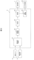
- FIG. It is a functional block diagram showing a control device. It is a flowchart figure which shows the control processing of a control apparatus.
- FIG. 4 is a plan view for explaining the shape of a predicted travel area; It is a figure for demonstrating the content displayed on the notification apparatus. It is a side view which shows the working machine which concerns on 2nd Embodiment.
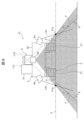
- FIG. 4 is a side view showing a working machine further comprising a rear ranging sensor, a left ranging sensor and a right ranging sensor;
- FIG. 4 is a rear view of the work machine further including a rear ranging sensor, a left ranging sensor, and a right ranging sensor;
- FIG. 1 is a side view showing the working machine according to the first embodiment.
- the working machine 1 of the present embodiment is, for example, a hydraulic excavator, and includes a lower traveling body 2 that travels by a power system, an upper revolving body 3 attached to the lower traveling body 2 so as to be able to turn in the left-right direction, and an upper A front device 4 that is attached to the revolving body 3 and performs work such as excavation is provided.
- the lower traveling body 2 and the upper revolving body 3 constitute the vehicle body of the work machine 1 .
- the lower traveling body 2 has a pair of left and right crawler belts 21, a traveling motor (not shown) that drives the pair of crawler belts 21, respectively, and a traveling controller 22 that controls the traveling motor and the like.
- the travel motor drives the left and right crawler belts 21 according to commands from the travel controller 22 .
- the undercarriage 2 can move forward or backward, turn left or right, or make a turn (also referred to as a stationary turn).
- the traveling controller 22 is electrically connected to the control device 5 to be described later, and controls the drive of the traveling motor according to the traveling control command from the control device 5 .
- “super pivot turning” means turning the lower traveling body 2 on the spot by rotating the left and right crawler belts 21 in opposite directions.
- the upper revolving body 3 has an operator's cab 31 and a machine room 32 .
- the operator's cab 31 is arranged, for example, on the left side of the upper revolving body 3, and is provided with an operator's seat for performing various operations of the work machine 1 while an operator is seated therein.
- the machine room 32 is arranged behind the driver's cab 31, for example.
- a swing motor (not shown) is arranged on the upper swing body 3 . When the turning motor is driven, the upper turning body 3 can turn with respect to the lower traveling body 2 .
- the front device 4 is formed to be vertically rotatable with respect to the upper revolving body 3 .
- the front device 4 includes a boom 41 connected to the upper swing body 3, an arm 42 connected to the boom 41, a bucket 43 connected to the arm 42, a boom cylinder 44 for driving the boom 41, and the arm 42. It has an arm cylinder 45 for driving and a bucket cylinder 46 for driving the bucket 43 via a bucket link or the like.
- the working machine 1 also includes a turning angle sensor 8 for detecting the relative turning angle between the upper turning body 3 and the lower traveling body 2, a notification device 7 for notifying the operator of the working machine 1 of information, and a control device 5 for controlling the working machine 1 .
- the turning angle sensor 8 is formed of, for example, a rotary encoder, measures the turning angle of the upper turning body 3 with respect to the lower traveling body 2, and outputs the measurement result to the control device 5.
- the notification device 7 is formed by, for example, a monitor and a speaker, and is arranged inside the driver's cab 31 .
- the notification device 7 is electrically connected to the control device 5 and notifies the operator of information via text or voice according to notification control commands from the control device 5 .
- the notification device 7 has a display unit 9 (described later) consisting of a monitor.
- the ranging sensor 6 is formed by, for example, a 1D to 3D type LiDAR, a millimeter wave radar, a stereo camera, or the like.
- the distance measuring sensor 6 is attached to the upper revolving body 3 (here, outside the windshield of the driver's cab 31).
- the mounting position and measurement position of the distance measuring sensor 6 are determined as follows. That is, as shown in FIG. Assuming that a straight line having the same angle as the uphill angle ⁇ is a first straight line L1, and a straight line connecting the mounting position of the distance measuring sensor 6 and the predicted travel point P1 is a second straight line L2, the distance measuring sensor 6 It is attached to the upper revolving body 3 so as to be positioned above L1, and measures the distance from the attachment position to the ground on the second straight line L2.
- the traveling plane S is a virtual plane when the crawler belt 21 travels straight.
- the predicted travel point P1 is a point-like area that exists on the travel plane S and is an area that is a certain distance D1 from the tip (here, the front end) of the crawler belt 21 .
- the position of the predicted travel point P1 (in other words, the distance D1) is obtained by multiplying the response time from when the control device 5 transmits a stop command to the travel controller 22 until the work machine 1 stops, for example, by the maximum travel speed of the vehicle body. It is determined based on the value obtained by the braking distance.
- the position of the predicted travel point P1 (in other words, the distance D1) may be longer than the braking distance.
- the maximum climbing angle ⁇ is the maximum angle of the slope F that the working machine 1 can climb. may be set. That is, the maximum climbing angle ⁇ may be set equal to the specified value, or may be set smaller than the specified value with an emphasis on safety.
- the first straight line L1 is a straight line that passes through the travel prediction point P1 and has an angle with respect to the travel plane S that is the same as the maximum climbing angle ⁇ .
- the distance measuring sensor 6 is positioned above the first straight line L1 and attached to the upper revolving body 3 . The distance measuring sensor 6 measures the distance from its mounting position to the ground along the second straight line L2, that is, the distance to the intersection of the second straight line L2 and the slope F, and outputs the measured result to the control device 5. do.
- the area of the ground measured by the distance measuring sensor 6 is assumed to be the predicted travel area T.
- the predicted travel area T is an area having various shapes, and may be, for example, a plurality of dot-like areas scattered around the work machine 1, or a linear (for example, linear or curved) area made up of continuous points. It may be an area, or an annular area (for example, an annular or polygonal annular) composed of continuous points so as to surround the work machine 1 .
- the shape of the predicted travel area T will be described later.
- the control device 5 includes, for example, a CPU (Central Processing Unit) that executes calculations, a ROM (Read Only Memory) as a secondary storage device that records programs for calculations, and storage of calculation progress and temporary control variables. It is composed of a microcomputer combined with a RAM (random access memory) as a temporary storage device that stores .
- a CPU Central Processing Unit
- ROM Read Only Memory
- FIG. 2 is a functional block diagram showing the control device.
- the control device 5 has a terrain shape acquisition unit 51 , a height difference calculation unit 52 , a determination unit 53 , an alarm unit 54 and a travel control unit 55 .
- the terrain shape acquisition unit 51 acquires the terrain shape of the predicted travel area T based on the distance measured by the range sensor 6 and the angle measured by the turning angle sensor 8 .
- the height difference calculator 52 calculates the height H1 (see FIG. 1) of the predicted travel area T based on the terrain shape of the predicted travel area T acquired by the terrain shape acquirer 51 .
- the height difference calculator 52 also calculates a difference (height difference H3 (see FIG. 1)) between the height H2 (see FIG. 1) of the traveling plane S and the height H1 of the predicted travel region T calculated above.
- the heights H1 and H2 are based on the mounting position of the distance measuring sensor 6, and are calculated based on the distance measured by the distance measuring sensor 6 and the inclination angle of the second straight line L2 with respect to the running plane S. .
- the determination unit 53 determines whether the height difference calculated by the height difference calculation unit 52 is equal to or greater than a preset threshold.
- the threshold value is set based on, for example, a specification value of the height difference that the work machine 1 can traverse. Further, the determination unit 53 sets a step detection flag based on the determination result as to whether or not the height difference is equal to or greater than the threshold. Specifically, when determining that the height difference is greater than or equal to the threshold value, the determining unit 53 determines that a step has been detected in the predicted travel area T and sets the “step detection flag” to “true”. On the other hand, when the height difference is smaller than the threshold, the determination unit 53 sets the "step detection flag” to "false”. As described above, the "step” referred to in this embodiment refers to a difference (height difference H3) between the height H2 of the driving plane S and the height H1 of the predicted driving area T being equal to or greater than a threshold.
- the reporting unit 54 issues a command to operate the notification device 7 when it is determined that the height difference is greater than or equal to the threshold. That is, the notification unit 54 outputs a command to the notification device 7 only when it is determined that the height difference is equal to or greater than the threshold.
- the travel control unit 55 outputs a command to the travel controller 22 to immediately decelerate and stop the travel of the lower travel body 2 .
- control processing of the control device 5 will be described below based on FIG.
- step S ⁇ b>1 the terrain shape acquisition unit 51 acquires the terrain shape of the predicted travel area T based on the measurement result of the distance sensor 6 and the detection result of the turning angle sensor 8 .
- step S2 following step S1 the height difference calculator 52 calculates the height H1 of the predicted travel area T based on the terrain shape of the predicted travel area T acquired in step S1.
- the height H1 of the predicted travel area T is, for example, the average value of the heights of the terrain shape of the predicted travel area T.
- step S3 the height difference calculator 52 calculates the difference (height difference H3) between the height H2 of the traveling plane S measured in advance and the height H1 of the predicted travel area T calculated in step S2. and outputs the calculated height difference to the determination unit 53 . Then, the determination unit 53 compares the height difference calculated by the height difference calculation unit 52 with a preset threshold value, and determines whether or not the calculated height difference is equal to or greater than the threshold value.
- step S4 the determination unit 53 determines that there is no step in the predicted travel area T, and sets the "step detection flag” to "false". This ends the control process.
- step S3 determines that the calculated height difference is greater than or equal to the threshold. If it is determined in step S3 that the calculated height difference is greater than or equal to the threshold, the control process proceeds to step S5.
- step S5 the determination unit 53 determines that there is a step in the predicted travel area T (in other words, the step is detected) and sets the "step detection flag" to "true”.
- step S6 the notification unit 54 receives the "true" level difference detection flag and outputs to the notification device 7 a command to operate the notification device 7.
- the notification device 7 notifies the operator that a step has been detected in the predicted travel area T through character display or voice in accordance with a command from the notification unit 54 .
- step S7 following step S6, the travel control unit 55 outputs to the travel controller 22 a command to immediately decelerate and stop the travel of the lower travel body 2.
- step S7 ends, a series of control processing ends.
- steps S6 and S7 may be performed at the same time. That is, upon receiving the step detection flag of "true", the alarm unit 54 outputs to the notification device 7, and at the same time, the travel control unit 55 outputs to the travel controller 22 a command to decelerate and stop.
- the step detection flag of "true” is received in this way, by immediately outputting a stop command to the traveling controller 22, the work machine 1 can be immediately stopped without causing a time lag. can enhance sexuality.
- the determination unit 53 shown in FIG. 2 may be directly connected to the travel control unit 55 so as to output to the travel control unit 55 as well.
- the control device 5 controls the vehicle to travel in a direction in which the difference in elevation is smaller than the threshold.
- the traveling body 2 may be controlled. For example, when a step is detected in front of the work machine 1 and no step is detected in the rear of the work machine 1, the control device 5 permits the lower traveling body 2 to travel rearward, and the lower traveling body 2 is allowed to travel backward. Control to run backwards. By doing so, it is possible to maintain the stability of the vehicle body and prevent the working machine 1 from stopping.
- the predicted traveling point P1 is separated from the crawler belts 21 by a certain distance D1, and the maximum Assuming that a straight line having the same angle as the uphill angle ⁇ is a first straight line L1, and a straight line connecting the mounting position of the distance measuring sensor 6 and the predicted travel point P1 is a second straight line L2, the distance measuring sensor 6 It is attached to the upper revolving body 3 so as to be positioned above L1, and measures the distance from the attachment position to the ground on the second straight line L2. In this way, since the distance measuring sensor 6 can measure the distance at an angle larger than the maximum climbing angle .theta., it is possible to reliably detect a level difference exceeding the maximum climbing angle .theta.
- the control device 5 operates the notification device 7 so that the operator of the work machine 1 can be notified of the information via the notification device 7 .
- the operator can be made aware that there is a step in the predicted travel area T. Therefore, by stopping the work machine 1, the operator can prevent the crawler belt 21 from falling on a step or the work machine 1 from falling from a step, so that the vehicle body stability of the work machine 1 can be maintained. It is possible to suppress the decrease in productivity due to the instability of the vehicle body.
- the control device 5 controls the lower traveling body 2 to stop traveling. By doing so, even if the operator notices that a step has been detected via the notification device 7, but does not stop the working machine 1 immediately, or continues to operate the traveling machine 1 for some reason, By quickly decelerating and stopping the undercarriage 2, it is possible to prevent the working machine 1 from falling into an unstable state. Therefore, it is possible to maintain the stability of the vehicle body and to reliably suppress the decrease in productivity due to the instability of the vehicle body.
- the distance measuring sensor 6 is attached to the upper revolving body 3, it is possible to reliably suppress the influence of rotational vibration on the measurement accuracy compared to the conventional case where it is attached to the front device 4.
- the predicted travel area T has various shapes. Four representative examples (T1 to T4) shown in FIG. 4 will be described below.
- the predicted travel area T1 shown in FIG. 4 is the most basic predicted travel area, and is set as a plurality of dot-like areas on the lower traveling body 2 in the longitudinal direction.
- the predicted travel area T1 is composed of a total of four point-like areas, one on each of the left and right crawler belts 21 in the front and rear thereof. Therefore, the terrain shape acquisition unit 51 of the control device 5 acquires the terrain shape of each of the four dot-like regions. In this way, it is possible to detect a step in front of the work machine 1 in the front-rear direction of the lower traveling body 2 .
- the upper rotating body 3 may be rotated backward and the distance measuring sensor 6 may be used for measurement.
- the predicted travel area T2 shown in FIG. 4 is set as a plurality of linear areas along the left-right direction of the lower traveling body 2 .
- the predicted travel area T2 consists of a total of four linear areas, one each for the front and rear of the left and right crawler belts 21 .
- the length of each region may be matched to the width of the crawler belt 21, for example.
- the terrain shape acquisition unit 51 of the control device 5 acquires the terrain shape that matches the width of the crawler belts 21 before and after the left and right crawler belts 21 .
- the average height of the terrain shape in the predicted travel area T2 can be used as the height of the terrain shape. Therefore, it is possible to calculate the height difference with high accuracy.
- the upper rotating body 3 may be rotated backward and the distance measuring sensor 6 may be used for measurement.
- a travel prediction area T3 shown in FIG. 4 is set as an annular area surrounding the lower traveling body 2 .
- the predicted travel area T3 is an annular or elliptical annular area surrounding the lower traveling body 2 .
- the terrain shape acquisition unit 51 of the control device 5 acquires the terrain shape of the entire circumference of the lower traveling body 2 . In this way, even a step on the side of the undercarriage 2 can be detected. Therefore, for example, when the lower traveling body 2 makes a pivot turn, it is possible to prevent a situation in which the crawler belt 21 falls on a step on the side of the lower traveling body 2 and the vehicle body becomes unstable.
- the distance measuring sensor 6 may be used while the upper rotating body 3 is rotating.
- the predicted travel area T4 shown in FIG. Specifically, the predicted travel area T4 is composed of two linear areas extending in the traveling direction of the left and right crawler belts 21 .
- the terrain shape acquisition unit 51 of the control device 5 acquires the terrain shape linearly in the longitudinal direction of the lower traveling body 2 . In this way, it is possible to detect a step farther than the travel prediction point P1. It should be noted that when measuring the travel prediction region T4 behind the crawler belt 21, the upper rotating body 3 may be rotated backward and the distance measuring sensor 6 may be used for measurement.
- the predicted travel area may be a fan-shaped area that is a set of a plurality of radiation areas extending forward from the lower traveling body 2 .
- both the ridge line 10 indicating the position of the detected step and the position of the working machine 1 are displayed on the display unit 9 of the notification device 7, so that the operator can easily detect the step in the distance. You can quickly notice the situation and easily grasp the situation of steps.
- the conditions for acquiring the terrain shape of the predicted travel areas T1 to T4 change depending on whether the measurement range of the distance measuring sensor 6 is point-like, linear, or planar.
- the terrain shape of the predicted travel area T1 can be obtained regardless of whether the measurement range of the distance measuring sensor 6 is point-like, linear, or planar.
- the measurement range of the distance measuring sensor 6 must be linear or planar.
- the terrain shape of the predicted travel areas T2 and T3 regardless of whether the measurement range of the distance measuring sensor 6 is point-like, linear, or planar.
- the distance measuring sensor 6 continuously measures the distance while rotating the upper rotating body 3 (in other words, measures the distance so that the distance becomes a continuous point).
- the turning angle measured by the turning angle sensor 8 the terrain shape of the predicted travel areas T2 and T3 can be obtained.
- a second embodiment of the working machine 1 will be described below with reference to FIG.
- the work machine 1 of the second embodiment differs from the first embodiment in that it is applied to remote control.
- Only the contents different from the first embodiment due to the difference will be described.
- the work machine 1 of the second embodiment includes a remote control device 11 arranged at a location away from the work machine 1 and capable of transmitting an operation command to the control device 5; 11, and a wireless receiver 13 arranged on the upper rotating body 3 and receiving the command transmitted from the wireless transmitter 12. Radio receiver 13 outputs the received command to control device 5 .
- the distance measuring sensor 6 is attached to the upper revolving structure 3 (here, outside the windshield of the driver's cab 31). There is That is, on the traveling plane S of the crawler belt 21, it passes through the predicted traveling point P2 farther away from the work machine 1 than the predicted traveling point P1, and is at the same angle as the maximum climbing angle ⁇ with respect to the traveling plane S of the crawler belt 21, or Assuming that a straight line having an angle corresponding to this is a third straight line L3, and a straight line connecting the mounting position of the distance measuring sensor 6 and the remote controlled travel prediction point P2 is a fourth straight line L4, the distance measuring sensor 6 further It is attached to the upper revolving body 3 so as to be positioned above the 3rd straight line L3, and measures the distance from the attachment position to the ground on the 4th straight line L4.
- the predicted remote-controlled travel point P2 is a point that exists on the travel plane S and is a point that is a certain distance D2 (D2>D1) from the tip (here, the front end) of the crawler belt 21.
- the position of the predicted remote-controlled travel point P2 (in other words, the distance D2) is determined, for example, during the response time from when the control device 5 outputs a stop command to the travel controller 22 to when the work machine 1 stops.
- a value obtained by multiplying the value obtained by adding the time required for the operation command from the device 11 to reach the control device 5 via the wireless transmitter 12 and the wireless receiver 13 by the maximum running speed of the vehicle body, that is, the remote It is determined based on the braking distance due to the operation.
- the position of the predicted remote controlled travel point P2 (in other words, the distance D2) may be longer than the remote controlled braking distance.
- the area of the ground measured by the distance measuring sensor 6 is assumed to be the predicted remote-controlled travel area W.
- the predicted remote-controlled travel region W has various shapes like the predicted travel region T of the first embodiment, and has a shape shown in FIG. 4, for example.
- the terrain shape acquisition unit 51 acquires the terrain shape of the remote-controlled travel prediction area W based on the measurement result of the distance sensor 6 and the detection result of the turning angle sensor 8 .
- the height difference calculator 52 calculates the height H4 (see FIG. 6) of the predicted remote-controlled travel area W based on the terrain shape of the predicted remote-controlled travel area W acquired by the terrain shape acquisition section 51 . Further, the height difference calculator 52 calculates a difference (height difference H6 (see FIG. 6)) between the height H5 (see FIG. 6) of the traveling plane S and the height H4 of the predicted remote-controlled travel region W.
- the heights H4 and H5 are based on the mounting position of the distance measuring sensor 6, and are calculated based on the distance measured by the distance measuring sensor 6 and the inclination angle of the fourth straight line L4 with respect to the running plane S. .
- the determination unit 53, the alarm unit 54, and the travel control unit 55 are the same as those in the first embodiment. Also, the control processing regarding the control device 5 is different from that of the first embodiment in that it targets the remote-controlled travel prediction region W, but the rest is the same as that of the first embodiment, so redundant description will be omitted.
- the operator When operating the work machine 1 remotely, the operator performs each operation from a location away from the work machine 1, for example, based on the image of a camera (not shown) mounted on the work machine 1.
- a communication delay occurs when the image of the camera and the operation command from the remote control device 11 are communicated wirelessly. Therefore, for example, when the operator uses the remote control device 11 to instruct the work machine 1 to travel, the operator may be late in noticing a step or the like due to poor visibility. Further, even if the operator promptly instructs to stop traveling via the remote control device 11, the braking distance of the work machine 1 may be different from that in the case where the operator actually rides the work machine 1 and operates it due to the wireless communication delay. become larger in comparison. As a result, there is a possibility that the working machine 1 will not be able to stop running in time, and the crawler belt 21 will fall down a step or the working machine 1 will fall from the step.
- a remote-controlled travel prediction point P2 is provided farther than the travel prediction point P1 in consideration of the increased braking distance, and the maximum distance to the traveling plane S while passing through the remotely-operated travel prediction point P2.
- the distance measuring sensor 6 By arranging the distance measuring sensor 6 above the third straight line L3 having the same angle as the uphill angle ⁇ , the predicted remote controlled travel area W becomes farther away from the work machine 1 .
- the present invention may have a plurality of ranging sensors.
- distance sensors may be attached to the rear of the upper revolving body 3 and to the sides of the upper revolving body 3 .
- the working machine 1 further includes a rear ranging sensor 6a, a left ranging sensor 6b, and a right ranging sensor 6c in addition to the ranging sensor 6 described above.
- the rear ranging sensor 6a is attached to the rear of the upper revolving body 3.
- the left ranging sensor 6b is attached to the left side of the upper rotating body 3
- the right ranging sensor 6c is attached to the right side of the upper rotating body 3, respectively.
- the mounting position and measurement position of the rear ranging sensor 6a, the left ranging sensor 6b and the right ranging sensor 6c are determined similarly to the ranging sensor 6 based on the predicted travel point and the maximum climbing angle.
- a first straight line L1a is defined as a straight line that passes through a predicted backward running point P1a that is a certain distance away from the crawler belt 21 on the running plane S and that has the same angle as the maximum climbing angle ⁇ with respect to the running plane S.
- the straight line connecting the mounting position of the rear ranging sensor 6a and the backward traveling prediction point P1a is defined as a second straight line L2a
- the rear ranging sensor 6a is positioned above the first straight line L1a. 3, and measures the distance from the mounting position to the ground on the second straight line L2a.
- the position of the predicted backward travel point P1a may be determined based on the braking distance in the same manner as the predicted travel point P1 of the first embodiment, or may be determined to be greater than the braking distance.
- a first straight line L1b is defined as a straight line that passes through the predicted left travel point P1b that is a certain distance from the crawler belt 21 on the travel plane S and that has the same angle as the maximum climbing angle ⁇ with respect to the travel plane S.
- the straight line connecting the mounting position of the left ranging sensor 6b and the left travel prediction point P1b is defined as a second straight line L2b
- the left ranging sensor 6b is turned upward so as to be positioned above the first straight line L1b. It is attached to the body 3 and measures the distance from the attachment position to the ground on the second straight line L2b.
- the position of the predicted left travel point P1b may be determined based on the braking distance, similarly to the predicted travel point P1 of the first embodiment, or may be determined to be greater than the braking distance.
- a first straight line L1c which passes through the predicted right running point P1c on the running plane S and has the same angle as the maximum uphill angle ⁇ with respect to the running plane S
- the right ranging sensor 6c is attached to the upper revolving structure 3 so as to be positioned above the first straight line L1c when the straight line connecting the mounting position and the right travel prediction point P1c is a second straight line L2c.
- the distance from the mounting position to the ground on the second straight line L2c is measured.
- the position of the predicted right travel point P1c may be determined based on the braking distance, similarly to the predicted travel point P1 of the first embodiment, or may be determined to be greater than the braking distance.
- the ranging sensor 6, the rear ranging sensor 6a, the left ranging sensor 6b, and the right ranging sensor 6c are each made up of, for example, a 2D type LiDAR, and their measurement areas are horizontal as shown in FIG. is a two-dimensional plane with a certain angle at
- the triangles shown in FIGS. 7 and 8 schematically show the measurement ranges of the left ranging sensor 6b and the rear ranging sensor 6a.
- the rear ranging sensor 6a By further providing the rear ranging sensor 6a, the left ranging sensor 6b and the right ranging sensor 6c in this way, the steps on the rear, left and right sides of the crawler belt 21 can be detected without the upper rotating body 3 rotating. Therefore, the stability of the vehicle body can be reliably maintained.
Landscapes
- Engineering & Computer Science (AREA)
- Mining & Mineral Resources (AREA)
- Civil Engineering (AREA)
- General Engineering & Computer Science (AREA)
- Structural Engineering (AREA)
- Component Parts Of Construction Machinery (AREA)
Abstract
Description
図1は第1実施形態に係る作業機械を示す側面図である。本実施形態の作業機械1は、例えば油圧ショベルであって、動力系により走行する下部走行体2と、下部走行体2に対して左右方向に旋回自在に取り付けられた上部旋回体3と、上部旋回体3に取り付けられるとともに掘削などの作業を行うフロント装置4とを備えている。本実施形態では、下部走行体2及び上部旋回体3は作業機械1の車体を構成する。
以下、図6を基に作業機械1の第2実施形態を説明する。第2実施形態の作業機械1は、遠隔操作に適用される点において上記第1実施形態と相違している。ここでは、その相違点によって上記第1実施形態との異なる内容のみを説明する。
2 下部走行体
3 上部旋回体
4 フロント装置
5 制御装置
6 測距センサ
6a 後方測距センサ
6b 左側測距センサ
6c 右側測距センサ
7 通知装置
8 旋回角度センサ
9 表示部
11 遠隔操作装置
12 無線送信機
13 無線受信機
21 履帯
F 斜面
L1,L1a,L1b,L1c 第1直線
L2,L2a,L2b,L2c 第2直線
L3 第3直線
L4 第4直線
P1 走行予測点
P1a 後方走行予測点
P1b 左側走行予測点
P1c 右側走行予測点
P2 遠隔操作走行予測点
S 走行平面
T,T1,T2,T3,T4 走行予測領域
W 遠隔操作走行予測領域
θ 最大登坂角度
Claims (9)
- 履帯を有する下部走行体と、前記下部走行体に旋回自在に設けられた上部旋回体とを備えた作業機械であって、
前記上部旋回体に取り付けられた少なくとも1つの測距センサと、
前記上部旋回体と前記下部走行体との相対旋回角度を検出する旋回角度センサと、
前記作業機械のオペレータに情報を通知する通知装置と、
前記下部走行体と前記通知装置とを制御する制御装置と、
を備え、
前記履帯の走行平面上において前記履帯から一定距離離れた走行予測点を通るとともに前記履帯の走行平面に対して前記作業機械の最大登坂角度に対応する角度を有する直線を第1直線、前記測距センサの取付位置と前記走行予測点とを結ぶ直線を第2直線としたときに、前記測距センサは、前記第1直線よりも上方に位置し、その取付位置から前記第2直線上の地面までの距離を計測し、
前記測距センサが計測した地面の領域を走行予測領域としたときに、前記制御装置は、前記測距センサの計測結果と前記旋回角度センサの検出結果とに基づいて前記走行予測領域の高さを算出し、算出した前記走行予測領域の高さと前記履帯の走行平面の高さとの高低差が予め設定された閾値以上であるか否かを判定し、前記高低差が前記閾値以上であると判定した場合に前記通知装置を作動させることを特徴とする作業機械。 - 前記制御装置は、前記高低差が前記閾値以上であると判定した場合に、前記下部走行体の走行を停止するように前記下部走行体を制御する請求項1に記載の作業機械。
- 前記制御装置は、前記高低差が前記閾値以上であると判定した場合に、前記高低差が前記閾値よりも小さい方向に走行するように前記下部走行体を制御する請求項1に記載の作業機械。
- 前記走行予測領域は、前記下部走行体の前後方向上の点状の領域である請求項1~3のいずれか一項に記載の作業機械。
- 前記走行予測領域は、前記下部走行体の左右方向に沿う線状の領域である請求項1~3のいずれか一項に記載の作業機械。
- 前記走行予測領域は、前記下部走行体を取り囲むような環状の領域である請求項1~3のいずれか一項に記載の作業機械。
- 前記走行予測領域は、前記下部走行体の前後方向に沿う線状の領域である請求項1~3のいずれか一項に記載の作業機械。
- 前記通知装置は、前記作業機械の位置及び前記高低差の位置を表示する表示部を有する請求項1~7のいずれか一項に記載の作業機械。
- 前記制御装置に操作指令を無線で送信する遠隔操作装置を更に備え、
前記履帯の走行平面上において前記走行予測点より前記作業機械に対して遠方にある遠隔操作走行予測点を通るとともに前記履帯の走行平面に対して前記作業機械の最大登坂角度に対応する角度を有する直線を第3直線、前記測距センサの取付位置と前記遠隔操作走行予測点とを結ぶ直線を第4直線としたときに、前記測距センサは、更に前記第3直線よりも上方に位置し、その取付位置から前記第4直線上の地面までの距離を計測し、
前記測距センサが計測した地面の領域を遠隔操作走行予測領域としたときに、前記制御装置は、前記測距センサの計測結果と前記旋回角度センサの検出結果とに基づいて前記遠隔操作走行予測領域の高さを算出し、算出した前記遠隔操作走行予測領域の高さと前記履帯の走行平面の高さとの高低差が前記閾値以上であるか否かを判定し、前記高低差が前記閾値以上であると判定した場合に前記通知装置を作動させる請求項1~8のいずれか一項に記載の作業機械。
Priority Applications (3)
| Application Number | Priority Date | Filing Date | Title |
|---|---|---|---|
| CN202280058615.2A CN117881858A (zh) | 2021-11-05 | 2022-10-31 | 作业机械 |
| US18/685,263 US20240376693A1 (en) | 2021-11-05 | 2022-10-31 | Work machine |
| EP22889934.0A EP4372155A4 (en) | 2021-11-05 | 2022-10-31 | CONSTRUCTION EQUIPMENT |
Applications Claiming Priority (2)
| Application Number | Priority Date | Filing Date | Title |
|---|---|---|---|
| JP2021-181027 | 2021-11-05 | ||
| JP2021181027A JP7191183B1 (ja) | 2021-11-05 | 2021-11-05 | 作業機械 |
Publications (1)
| Publication Number | Publication Date |
|---|---|
| WO2023080114A1 true WO2023080114A1 (ja) | 2023-05-11 |
Family
ID=84488920
Family Applications (1)
| Application Number | Title | Priority Date | Filing Date |
|---|---|---|---|
| PCT/JP2022/040739 Ceased WO2023080114A1 (ja) | 2021-11-05 | 2022-10-31 | 作業機械 |
Country Status (5)
| Country | Link |
|---|---|
| US (1) | US20240376693A1 (ja) |
| EP (1) | EP4372155A4 (ja) |
| JP (1) | JP7191183B1 (ja) |
| CN (1) | CN117881858A (ja) |
| WO (1) | WO2023080114A1 (ja) |
Cited By (1)
| Publication number | Priority date | Publication date | Assignee | Title |
|---|---|---|---|---|
| US20250010861A1 (en) * | 2023-06-30 | 2025-01-09 | Hitachi, Ltd. | Autonomous control system and autonomous control method |
Families Citing this family (3)
| Publication number | Priority date | Publication date | Assignee | Title |
|---|---|---|---|---|
| JP2025148762A (ja) * | 2024-03-26 | 2025-10-08 | 株式会社小松製作所 | 作業機械の表示システム、作業機械、及び作業機械の表示方法 |
| JP2025151065A (ja) | 2024-03-27 | 2025-10-09 | 日立建機株式会社 | 作業機械 |
| WO2026049059A1 (ja) * | 2024-09-02 | 2026-03-05 | 国立大学法人東北大学 | 動作計画装置、動作計画方法及びプログラム |
Citations (6)
| Publication number | Priority date | Publication date | Assignee | Title |
|---|---|---|---|---|
| JPH0586636A (ja) * | 1991-09-30 | 1993-04-06 | Komatsu Ltd | 作業車両の転倒防止装置 |
| JP2009208509A (ja) * | 2008-02-29 | 2009-09-17 | Yanmar Co Ltd | 作業車両 |
| JP2016172963A (ja) * | 2015-03-16 | 2016-09-29 | 住友重機械工業株式会社 | ショベル |
| WO2019026802A1 (ja) * | 2017-07-31 | 2019-02-07 | 住友重機械工業株式会社 | ショベル |
| JP2020133143A (ja) * | 2019-02-14 | 2020-08-31 | コベルコ建機株式会社 | 監視装置及び建設機械 |
| JP2020159142A (ja) | 2019-03-27 | 2020-10-01 | 日立建機株式会社 | 作業機械 |
Family Cites Families (2)
| Publication number | Priority date | Publication date | Assignee | Title |
|---|---|---|---|---|
| WO2019089853A1 (en) * | 2017-10-31 | 2019-05-09 | Agjunction Llc | Three-dimensional terrain mapping |
| CN111344460B (zh) * | 2017-12-04 | 2022-04-26 | 住友重机械工业株式会社 | 周边监视装置 |
-
2021
- 2021-11-05 JP JP2021181027A patent/JP7191183B1/ja active Active
-
2022
- 2022-10-31 CN CN202280058615.2A patent/CN117881858A/zh active Pending
- 2022-10-31 US US18/685,263 patent/US20240376693A1/en active Pending
- 2022-10-31 EP EP22889934.0A patent/EP4372155A4/en active Pending
- 2022-10-31 WO PCT/JP2022/040739 patent/WO2023080114A1/ja not_active Ceased
Patent Citations (6)
| Publication number | Priority date | Publication date | Assignee | Title |
|---|---|---|---|---|
| JPH0586636A (ja) * | 1991-09-30 | 1993-04-06 | Komatsu Ltd | 作業車両の転倒防止装置 |
| JP2009208509A (ja) * | 2008-02-29 | 2009-09-17 | Yanmar Co Ltd | 作業車両 |
| JP2016172963A (ja) * | 2015-03-16 | 2016-09-29 | 住友重機械工業株式会社 | ショベル |
| WO2019026802A1 (ja) * | 2017-07-31 | 2019-02-07 | 住友重機械工業株式会社 | ショベル |
| JP2020133143A (ja) * | 2019-02-14 | 2020-08-31 | コベルコ建機株式会社 | 監視装置及び建設機械 |
| JP2020159142A (ja) | 2019-03-27 | 2020-10-01 | 日立建機株式会社 | 作業機械 |
Non-Patent Citations (1)
| Title |
|---|
| See also references of EP4372155A4 |
Cited By (1)
| Publication number | Priority date | Publication date | Assignee | Title |
|---|---|---|---|---|
| US20250010861A1 (en) * | 2023-06-30 | 2025-01-09 | Hitachi, Ltd. | Autonomous control system and autonomous control method |
Also Published As
| Publication number | Publication date |
|---|---|
| JP7191183B1 (ja) | 2022-12-16 |
| CN117881858A (zh) | 2024-04-12 |
| JP2023069275A (ja) | 2023-05-18 |
| EP4372155A4 (en) | 2025-07-09 |
| US20240376693A1 (en) | 2024-11-14 |
| EP4372155A1 (en) | 2024-05-22 |
Similar Documents
| Publication | Publication Date | Title |
|---|---|---|
| JP7191183B1 (ja) | 作業機械 | |
| JP7182531B2 (ja) | 作業機械 | |
| JP6638831B2 (ja) | 建設機械 | |
| US10527731B2 (en) | Obstacle detection device | |
| KR102109155B1 (ko) | 굴삭기 안전제어 장치 및 방법 | |
| JP2008303648A (ja) | 作業機械の警報システム | |
| WO2020166241A1 (ja) | 監視装置及び建設機械 | |
| KR20170065341A (ko) | 전복 방지 기능을 가지는 굴삭기 및 굴삭기의 전복 방지 방법 | |
| JP2023181369A (ja) | 建設機械の障害物検出装置 | |
| JP2017145564A (ja) | 可動機械の安全装置 | |
| KR101461193B1 (ko) | 충돌방지장치를 구비한 크레인 후크 | |
| JP2022155631A (ja) | 作業機械の周囲監視装置 | |
| JP6838040B2 (ja) | 建設機械の障害物検出装置 | |
| KR20080099749A (ko) | 굴삭기의 작업장치 제어장치 및 제어방법 | |
| KR102677528B1 (ko) | 건설기계 | |
| JP7532696B2 (ja) | 重機周りの障害物検知システム | |
| JP2002047692A (ja) | 作業用自走機械 | |
| US20250137227A1 (en) | Project path of travel of blade on a motor grader | |
| US20250297462A1 (en) | Work machine and method of controlling work machine | |
| JP7790768B1 (ja) | 工事用安全装置 | |
| KR102582024B1 (ko) | 선택적 전자기파 방출을 통한 중장비 모니터링 시스템 | |
| KR102944860B1 (ko) | 차량의 추돌 위험 감지 방법 및 이를 이용한 추돌 위험 감지시스템 | |
| JP2024143779A (ja) | 作業機械 | |
| JP2024052406A (ja) | 建設機械 | |
| KR20250127578A (ko) | 건설 장비용 충돌 방지 시스템을 포함하는 건설 장비, 및 건설 장비를 제어하기 위한 방법 |
Legal Events
| Date | Code | Title | Description |
|---|---|---|---|
| 121 | Ep: the epo has been informed by wipo that ep was designated in this application |
Ref document number: 22889934 Country of ref document: EP Kind code of ref document: A1 |
|
| WWE | Wipo information: entry into national phase |
Ref document number: 2022889934 Country of ref document: EP |
|
| ENP | Entry into the national phase |
Ref document number: 2022889934 Country of ref document: EP Effective date: 20240213 |
|
| WWE | Wipo information: entry into national phase |
Ref document number: 202280058615.2 Country of ref document: CN |
|
| NENP | Non-entry into the national phase |
Ref country code: DE |