WO2023080123A1 - 光拡散シート、バックライトユニット、液晶表示装置、情報機器、及び光拡散シートの製造方法 - Google Patents
光拡散シート、バックライトユニット、液晶表示装置、情報機器、及び光拡散シートの製造方法 Download PDFInfo
- Publication number
- WO2023080123A1 WO2023080123A1 PCT/JP2022/040810 JP2022040810W WO2023080123A1 WO 2023080123 A1 WO2023080123 A1 WO 2023080123A1 JP 2022040810 W JP2022040810 W JP 2022040810W WO 2023080123 A1 WO2023080123 A1 WO 2023080123A1
- Authority
- WO
- WIPO (PCT)
- Prior art keywords
- light diffusion
- diffusion sheet
- less
- shape
- recesses
- Prior art date
- Legal status (The legal status is an assumption and is not a legal conclusion. Google has not performed a legal analysis and makes no representation as to the accuracy of the status listed.)
- Ceased
Links
Images








Classifications
-
- C—CHEMISTRY; METALLURGY
- C08—ORGANIC MACROMOLECULAR COMPOUNDS; THEIR PREPARATION OR CHEMICAL WORKING-UP; COMPOSITIONS BASED THEREON
- C08J—WORKING-UP; GENERAL PROCESSES OF COMPOUNDING; AFTER-TREATMENT NOT COVERED BY SUBCLASSES C08B, C08C, C08F, C08G or C08H
- C08J5/00—Manufacture of articles or shaped materials containing macromolecular substances
- C08J5/18—Manufacture of films or sheets
-
- G—PHYSICS
- G02—OPTICS
- G02B—OPTICAL ELEMENTS, SYSTEMS OR APPARATUS
- G02B5/00—Optical elements other than lenses
- G02B5/02—Diffusing elements; Afocal elements
-
- B—PERFORMING OPERATIONS; TRANSPORTING
- B29—WORKING OF PLASTICS; WORKING OF SUBSTANCES IN A PLASTIC STATE IN GENERAL
- B29D—PRODUCING PARTICULAR ARTICLES FROM PLASTICS OR FROM SUBSTANCES IN A PLASTIC STATE
- B29D11/00—Producing optical elements, e.g. lenses or prisms
- B29D11/0074—Production of other optical elements not provided for in B29D11/00009- B29D11/0073
- B29D11/00798—Producing diffusers
-
- B—PERFORMING OPERATIONS; TRANSPORTING
- B29—WORKING OF PLASTICS; WORKING OF SUBSTANCES IN A PLASTIC STATE IN GENERAL
- B29C—SHAPING OR JOINING OF PLASTICS; SHAPING OF MATERIAL IN A PLASTIC STATE, NOT OTHERWISE PROVIDED FOR; AFTER-TREATMENT OF THE SHAPED PRODUCTS, e.g. REPAIRING
- B29C48/00—Extrusion moulding, i.e. expressing the moulding material through a die or nozzle which imparts the desired form; Apparatus therefor
- B29C48/25—Component parts, details or accessories; Auxiliary operations
- B29C48/30—Extrusion nozzles or dies
- B29C48/305—Extrusion nozzles or dies having a wide opening, e.g. for forming sheets
-
- B—PERFORMING OPERATIONS; TRANSPORTING
- B29—WORKING OF PLASTICS; WORKING OF SUBSTANCES IN A PLASTIC STATE IN GENERAL
- B29C—SHAPING OR JOINING OF PLASTICS; SHAPING OF MATERIAL IN A PLASTIC STATE, NOT OTHERWISE PROVIDED FOR; AFTER-TREATMENT OF THE SHAPED PRODUCTS, e.g. REPAIRING
- B29C48/00—Extrusion moulding, i.e. expressing the moulding material through a die or nozzle which imparts the desired form; Apparatus therefor
- B29C48/25—Component parts, details or accessories; Auxiliary operations
- B29C48/88—Thermal treatment of the stream of extruded material, e.g. cooling
- B29C48/90—Thermal treatment of the stream of extruded material, e.g. cooling with calibration or sizing, i.e. combined with fixing or setting of the final dimensions of the extruded article
-
- B—PERFORMING OPERATIONS; TRANSPORTING
- B29—WORKING OF PLASTICS; WORKING OF SUBSTANCES IN A PLASTIC STATE IN GENERAL
- B29C—SHAPING OR JOINING OF PLASTICS; SHAPING OF MATERIAL IN A PLASTIC STATE, NOT OTHERWISE PROVIDED FOR; AFTER-TREATMENT OF THE SHAPED PRODUCTS, e.g. REPAIRING
- B29C59/00—Surface shaping of articles, e.g. embossing; Apparatus therefor
- B29C59/02—Surface shaping of articles, e.g. embossing; Apparatus therefor by mechanical means, e.g. pressing
- B29C59/04—Surface shaping of articles, e.g. embossing; Apparatus therefor by mechanical means, e.g. pressing using rollers or endless belts
-
- B—PERFORMING OPERATIONS; TRANSPORTING
- B29—WORKING OF PLASTICS; WORKING OF SUBSTANCES IN A PLASTIC STATE IN GENERAL
- B29D—PRODUCING PARTICULAR ARTICLES FROM PLASTICS OR FROM SUBSTANCES IN A PLASTIC STATE
- B29D11/00—Producing optical elements, e.g. lenses or prisms
- B29D11/0073—Optical laminates
-
- B—PERFORMING OPERATIONS; TRANSPORTING
- B29—WORKING OF PLASTICS; WORKING OF SUBSTANCES IN A PLASTIC STATE IN GENERAL
- B29D—PRODUCING PARTICULAR ARTICLES FROM PLASTICS OR FROM SUBSTANCES IN A PLASTIC STATE
- B29D7/00—Producing flat articles, e.g. films or sheets
- B29D7/01—Films or sheets
-
- B—PERFORMING OPERATIONS; TRANSPORTING
- B32—LAYERED PRODUCTS
- B32B—LAYERED PRODUCTS, i.e. PRODUCTS BUILT-UP OF STRATA OF FLAT OR NON-FLAT, e.g. CELLULAR OR HONEYCOMB, FORM
- B32B27/00—Layered products comprising a layer of synthetic resin
- B32B27/36—Layered products comprising a layer of synthetic resin comprising polyesters
- B32B27/365—Layered products comprising a layer of synthetic resin comprising polyesters comprising polycarbonates
-
- B—PERFORMING OPERATIONS; TRANSPORTING
- B32—LAYERED PRODUCTS
- B32B—LAYERED PRODUCTS, i.e. PRODUCTS BUILT-UP OF STRATA OF FLAT OR NON-FLAT, e.g. CELLULAR OR HONEYCOMB, FORM
- B32B3/00—Layered products comprising a layer with external or internal discontinuities or unevennesses, or a layer of non-planar shape; Layered products comprising a layer having particular features of form
- B32B3/26—Layered products comprising a layer with external or internal discontinuities or unevennesses, or a layer of non-planar shape; Layered products comprising a layer having particular features of form characterised by a particular shape of the outline of the cross-section of a continuous layer; characterised by a layer with cavities or internal voids ; characterised by an apertured layer
- B32B3/30—Layered products comprising a layer with external or internal discontinuities or unevennesses, or a layer of non-planar shape; Layered products comprising a layer having particular features of form characterised by a particular shape of the outline of the cross-section of a continuous layer; characterised by a layer with cavities or internal voids ; characterised by an apertured layer characterised by a layer formed with recesses or projections, e.g. hollows, grooves, protuberances, ribs
-
- F—MECHANICAL ENGINEERING; LIGHTING; HEATING; WEAPONS; BLASTING
- F21—LIGHTING
- F21S—NON-PORTABLE LIGHTING DEVICES; SYSTEMS THEREOF; VEHICLE LIGHTING DEVICES SPECIALLY ADAPTED FOR VEHICLE EXTERIORS
- F21S2/00—Systems of lighting devices, not provided for in main groups F21S4/00 - F21S10/00 or F21S19/00, e.g. of modular construction
-
- F—MECHANICAL ENGINEERING; LIGHTING; HEATING; WEAPONS; BLASTING
- F21—LIGHTING
- F21V—FUNCTIONAL FEATURES OR DETAILS OF LIGHTING DEVICES OR SYSTEMS THEREOF; STRUCTURAL COMBINATIONS OF LIGHTING DEVICES WITH OTHER ARTICLES, NOT OTHERWISE PROVIDED FOR
- F21V3/00—Globes; Bowls; Cover glasses
-
- F—MECHANICAL ENGINEERING; LIGHTING; HEATING; WEAPONS; BLASTING
- F21—LIGHTING
- F21V—FUNCTIONAL FEATURES OR DETAILS OF LIGHTING DEVICES OR SYSTEMS THEREOF; STRUCTURAL COMBINATIONS OF LIGHTING DEVICES WITH OTHER ARTICLES, NOT OTHERWISE PROVIDED FOR
- F21V5/00—Refractors for light sources
- F21V5/02—Refractors for light sources of prismatic shape
-
- G—PHYSICS
- G02—OPTICS
- G02B—OPTICAL ELEMENTS, SYSTEMS OR APPARATUS
- G02B5/00—Optical elements other than lenses
- G02B5/02—Diffusing elements; Afocal elements
- G02B5/0268—Diffusing elements; Afocal elements characterized by the fabrication or manufacturing method
-
- G—PHYSICS
- G02—OPTICS
- G02B—OPTICAL ELEMENTS, SYSTEMS OR APPARATUS
- G02B5/00—Optical elements other than lenses
- G02B5/02—Diffusing elements; Afocal elements
- G02B5/0273—Diffusing elements; Afocal elements characterized by the use
- G02B5/0278—Diffusing elements; Afocal elements characterized by the use used in transmission
-
- G—PHYSICS
- G02—OPTICS
- G02F—OPTICAL DEVICES OR ARRANGEMENTS FOR THE CONTROL OF LIGHT BY MODIFICATION OF THE OPTICAL PROPERTIES OF THE MEDIA OF THE ELEMENTS INVOLVED THEREIN; NON-LINEAR OPTICS; FREQUENCY-CHANGING OF LIGHT; OPTICAL LOGIC ELEMENTS; OPTICAL ANALOGUE/DIGITAL CONVERTERS
- G02F1/00—Devices or arrangements for the control of the intensity, colour, phase, polarisation or direction of light arriving from an independent light source, e.g. switching, gating or modulating; Non-linear optics
- G02F1/01—Devices or arrangements for the control of the intensity, colour, phase, polarisation or direction of light arriving from an independent light source, e.g. switching, gating or modulating; Non-linear optics for the control of the intensity, phase, polarisation or colour
- G02F1/13—Devices or arrangements for the control of the intensity, colour, phase, polarisation or direction of light arriving from an independent light source, e.g. switching, gating or modulating; Non-linear optics for the control of the intensity, phase, polarisation or colour based on liquid crystals, e.g. single liquid crystal display cells
- G02F1/133—Constructional arrangements; Operation of liquid crystal cells; Circuit arrangements
- G02F1/1333—Constructional arrangements; Manufacturing methods
- G02F1/1335—Structural association of cells with optical devices, e.g. polarisers or reflectors
- G02F1/1336—Illuminating devices
-
- G—PHYSICS
- G02—OPTICS
- G02F—OPTICAL DEVICES OR ARRANGEMENTS FOR THE CONTROL OF LIGHT BY MODIFICATION OF THE OPTICAL PROPERTIES OF THE MEDIA OF THE ELEMENTS INVOLVED THEREIN; NON-LINEAR OPTICS; FREQUENCY-CHANGING OF LIGHT; OPTICAL LOGIC ELEMENTS; OPTICAL ANALOGUE/DIGITAL CONVERTERS
- G02F1/00—Devices or arrangements for the control of the intensity, colour, phase, polarisation or direction of light arriving from an independent light source, e.g. switching, gating or modulating; Non-linear optics
- G02F1/01—Devices or arrangements for the control of the intensity, colour, phase, polarisation or direction of light arriving from an independent light source, e.g. switching, gating or modulating; Non-linear optics for the control of the intensity, phase, polarisation or colour
- G02F1/13—Devices or arrangements for the control of the intensity, colour, phase, polarisation or direction of light arriving from an independent light source, e.g. switching, gating or modulating; Non-linear optics for the control of the intensity, phase, polarisation or colour based on liquid crystals, e.g. single liquid crystal display cells
- G02F1/133—Constructional arrangements; Operation of liquid crystal cells; Circuit arrangements
- G02F1/1333—Constructional arrangements; Manufacturing methods
- G02F1/1335—Structural association of cells with optical devices, e.g. polarisers or reflectors
- G02F1/1336—Illuminating devices
- G02F1/133602—Direct backlight
- G02F1/133606—Direct backlight including a specially adapted diffusing, scattering or light controlling members
-
- B—PERFORMING OPERATIONS; TRANSPORTING
- B29—WORKING OF PLASTICS; WORKING OF SUBSTANCES IN A PLASTIC STATE IN GENERAL
- B29C—SHAPING OR JOINING OF PLASTICS; SHAPING OF MATERIAL IN A PLASTIC STATE, NOT OTHERWISE PROVIDED FOR; AFTER-TREATMENT OF THE SHAPED PRODUCTS, e.g. REPAIRING
- B29C48/00—Extrusion moulding, i.e. expressing the moulding material through a die or nozzle which imparts the desired form; Apparatus therefor
- B29C48/03—Extrusion moulding, i.e. expressing the moulding material through a die or nozzle which imparts the desired form; Apparatus therefor characterised by the shape of the extruded material at extrusion
- B29C48/07—Flat, e.g. panels
- B29C48/08—Flat, e.g. panels flexible, e.g. films
-
- B—PERFORMING OPERATIONS; TRANSPORTING
- B29—WORKING OF PLASTICS; WORKING OF SUBSTANCES IN A PLASTIC STATE IN GENERAL
- B29K—INDEXING SCHEME ASSOCIATED WITH SUBCLASSES B29B, B29C OR B29D, RELATING TO MOULDING MATERIALS OR TO MATERIALS FOR MOULDS, REINFORCEMENTS, FILLERS OR PREFORMED PARTS, e.g. INSERTS
- B29K2069/00—Use of PC, i.e. polycarbonates or derivatives thereof, as moulding material
-
- B—PERFORMING OPERATIONS; TRANSPORTING
- B29—WORKING OF PLASTICS; WORKING OF SUBSTANCES IN A PLASTIC STATE IN GENERAL
- B29K—INDEXING SCHEME ASSOCIATED WITH SUBCLASSES B29B, B29C OR B29D, RELATING TO MOULDING MATERIALS OR TO MATERIALS FOR MOULDS, REINFORCEMENTS, FILLERS OR PREFORMED PARTS, e.g. INSERTS
- B29K2105/00—Condition, form or state of moulded material or of the material to be shaped
- B29K2105/0079—Liquid crystals
-
- B—PERFORMING OPERATIONS; TRANSPORTING
- B29—WORKING OF PLASTICS; WORKING OF SUBSTANCES IN A PLASTIC STATE IN GENERAL
- B29L—INDEXING SCHEME ASSOCIATED WITH SUBCLASS B29C, RELATING TO PARTICULAR ARTICLES
- B29L2011/00—Optical elements, e.g. lenses, prisms
-
- B—PERFORMING OPERATIONS; TRANSPORTING
- B29—WORKING OF PLASTICS; WORKING OF SUBSTANCES IN A PLASTIC STATE IN GENERAL
- B29L—INDEXING SCHEME ASSOCIATED WITH SUBCLASS B29C, RELATING TO PARTICULAR ARTICLES
- B29L2031/00—Other particular articles
- B29L2031/34—Electrical apparatus, e.g. sparking plugs or parts thereof
- B29L2031/3475—Displays, monitors, TV-sets, computer screens
-
- B—PERFORMING OPERATIONS; TRANSPORTING
- B32—LAYERED PRODUCTS
- B32B—LAYERED PRODUCTS, i.e. PRODUCTS BUILT-UP OF STRATA OF FLAT OR NON-FLAT, e.g. CELLULAR OR HONEYCOMB, FORM
- B32B2307/00—Properties of the layers or laminate
- B32B2307/40—Properties of the layers or laminate having particular optical properties
- B32B2307/414—Translucent
-
- B—PERFORMING OPERATIONS; TRANSPORTING
- B32—LAYERED PRODUCTS
- B32B—LAYERED PRODUCTS, i.e. PRODUCTS BUILT-UP OF STRATA OF FLAT OR NON-FLAT, e.g. CELLULAR OR HONEYCOMB, FORM
- B32B2457/00—Electrical equipment
- B32B2457/20—Displays, e.g. liquid crystal displays, plasma displays
- B32B2457/202—LCD, i.e. liquid crystal displays
-
- F—MECHANICAL ENGINEERING; LIGHTING; HEATING; WEAPONS; BLASTING
- F21—LIGHTING
- F21Y—INDEXING SCHEME ASSOCIATED WITH SUBCLASSES F21K, F21L, F21S and F21V, RELATING TO THE FORM OR THE KIND OF THE LIGHT SOURCES OR OF THE COLOUR OF THE LIGHT EMITTED
- F21Y2105/00—Planar light sources
- F21Y2105/10—Planar light sources comprising a two-dimensional [2D] array of point-like light-generating elements
-
- F—MECHANICAL ENGINEERING; LIGHTING; HEATING; WEAPONS; BLASTING
- F21—LIGHTING
- F21Y—INDEXING SCHEME ASSOCIATED WITH SUBCLASSES F21K, F21L, F21S and F21V, RELATING TO THE FORM OR THE KIND OF THE LIGHT SOURCES OR OF THE COLOUR OF THE LIGHT EMITTED
- F21Y2115/00—Light-generating elements of semiconductor light sources
- F21Y2115/10—Light-emitting diodes [LED]
-
- F—MECHANICAL ENGINEERING; LIGHTING; HEATING; WEAPONS; BLASTING
- F21—LIGHTING
- F21Y—INDEXING SCHEME ASSOCIATED WITH SUBCLASSES F21K, F21L, F21S and F21V, RELATING TO THE FORM OR THE KIND OF THE LIGHT SOURCES OR OF THE COLOUR OF THE LIGHT EMITTED
- F21Y2115/00—Light-generating elements of semiconductor light sources
- F21Y2115/30—Semiconductor lasers
Definitions
- the scratch resistance can be improved.
- the dimension Wr may be an average value of a dimension Wrx occupied by the curved portion of the top of the ridge in the first direction and a dimension Wry occupied by the curved portion of the top of the ridge in the second direction. . By doing so, it becomes easier to manufacture a light diffusion sheet excellent in scratch resistance and luminance uniformity.
- the plurality of recesses are provided only on the first surface, and the second surface is a matte surface, thereby suppressing wear and damage on the second surface and improving brightness uniformity. can be further improved.
- a liquid crystal display device includes the aforementioned backlight unit according to the present disclosure and a liquid crystal display panel.
- the above-described light diffusion sheet according to the present disclosure can be manufactured at low cost.
- FIG. 10 is a cross-sectional view of a backlight unit according to a modified example
- the liquid crystal display device 50 of the present embodiment can be used for various information devices (for example, in-vehicle devices such as car navigation systems, personal computers, mobile phones, personal digital assistants, portable game machines, copiers, ticket vending machines, automated teller machines, etc.). ) is used as a display device incorporated in
- the reflective sheet 41 is composed of, for example, a white film made of polyethylene terephthalate resin, a silver-deposited film, or the like.
- the angle formed by the wall surfaces of the recesses 22 (slopes of a substantially inverted polygonal pyramid or a substantially inverted polygonal truncated pyramid) and the sheet surface of the first light diffusion sheet 43 (virtual mirror surface without the recesses 22) is, for example, 40 degrees or more and 65 degrees or less. .
- the apex angle of the concave portion 22 is, for example, 50 degrees or more and 100 degrees or less.
- the second surface 43b of the first light diffusion sheet 43 may be a mirror surface, but is preferably a matte surface in order to improve diffusion.
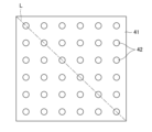
- FIG. 4 illustrates a state in which the concave portions 22 formed in a substantially inverted square pyramid shape are arranged in a 5 ⁇ 5 matrix on the first surface 43 a of the first light diffusion sheet 43 .
- the plurality of recesses 22 may be formed in a substantially inverted polygonal pyramid shape or a substantially inverted polygonal truncated pyramid shape.
- the plurality of recesses 22 may be regularly arranged two-dimensionally.
- the "inverted polygonal pyramid (trapezoid)" is preferably a triangular pyramid (trapezoid), a quadrangular pyramid (trapezoid), or a hexagonal pyramid (trapezoid) that can be two-dimensionally arranged without gaps.
- Molds metal rolls
- an "inverted polygonal pyramid ( Inverted quadrangular pyramid (trapezoid) may be selected as "trapezoid)".
- the first light diffusing sheet 43 preferably does not contain a diffusing agent from the viewpoint of the reflection and refraction effects of the substantially inverted polygonal pyramid shape and the light diffusing effect of the diffusing agent.
- the matrix may be 100% by mass, and the content of the diffusing agent may be, for example, 0.1% by mass or more (preferably 0.3% by mass or more) and 10% by mass or less (preferably 8% by mass or less).
- the difference between the refractive index of the diffusing agent and the refractive index of the matrix of the substrate layer 21 is 0.01 or more, preferably 0.03 or more, more preferably 0.05 or more, still more preferably 0.1 or more, and most preferably may be 0.15 or more. If the difference between the refractive index of the diffusing agent and the refractive index of the matrix of the substrate layer 21 is less than 0.01, the diffusing effect of the diffusing agent will be insufficient.
- the thickness of the first light diffusion sheet 43 is not particularly limited, but may be, for example, 3 mm or less (preferably 2 mm or less, more preferably 1.5 mm or less, still more preferably 1 mm or less) and 0.1 mm or more. .
- 3 mm or less preferably 2 mm or less, more preferably 1.5 mm or less, still more preferably 1 mm or less
- 0.1 mm or more preferably 3 mm or less
- the thickness of the first light diffusion sheet 43 exceeds 3 mm, it becomes difficult to achieve thinning of the liquid crystal display.
- the thickness of the first light diffusion sheet 43 is less than 0.1 mm, it becomes difficult to exhibit the effect of improving the brightness uniformity.
- the thickness of the recess forming layer is greater than the maximum depth of the recesses 22. have.
- the thickness should be greater than 20 ⁇ m.
- the first light diffusion sheet 43 may have a structure of three or more layers including a substrate layer and a recess forming layer. Alternatively, the substrate layer and the recess-forming layer may be configured as separate sheets, and the two may be laminated or arranged separately.
- the reverse shape of the roll surface is transferred to the resin, so that the desired uneven shape is formed on the surface of the diffusion sheet. It can be shaped.
- the shape transferred to the resin does not always correspond to the shape of the roll surface that is 100% transferred, the shape of the roll surface may be designed by calculating backward from the degree of transfer.
- the first surface 43a of the first light diffusion sheet 43 is provided with a plurality of concave portions 22 that are formed, for example, in the shape of a substantially inverted square pyramid.
- the plurality of recesses 22 may be formed in a substantially inverted regular quadrangular truncated pyramid shape.
- a center 22 a of the recess 22 is the deepest part of the recess 22 .
- the plurality of recesses 22 are arranged along an X direction (first direction) and a Y direction (second direction) that are orthogonal to each other. Adjacent recesses 22 are separated by ridgelines 23 .
- the ridgeline 23 extends along the X direction and the Y direction.
- the ratio Wr/P is 0.00, where P is the arrangement pitch of the recesses 22 and Wr is the dimension occupied by the curved portions of the tops of the ridges 23 in the arrangement direction of the recesses 22 . It must be 3 or less, more preferably 0.2 or less, and even more preferably 0.1 or less.
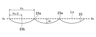
- the interval (horizontal distance) between the centers 22a of the recesses 22 adjacent in the X direction is equal to the arrangement pitch Px of the recesses 22 in the X direction.
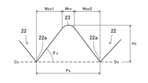
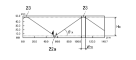
- the dimension occupied by the curved portion at the top of the ridgeline 23 in the X direction is Wrx.
- the dimensions occupied in the X direction by the linear portions of the wall surfaces (the slopes of the inverted quadrangular pyramid) of the concave portions 22 adjacent to each other with the ridge line 23 interposed therebetween are Wsx1 and Wsx2.
- the angle formed by the wall surface of the concave portion 22 (slope of the inverted quadrangular pyramid) and the sheet surface in the X direction is ⁇ x.
- the height from the center 22a of the recess 22 to the apex (midpoint between the intersections 23a) of the ridgeline 23 (the ridgeline 23 extending in the Y direction) is Hx.
- the arrangement pitch P of the plurality of recesses 22 is 50 ⁇ m or more and 500 ⁇ m or less, and the wall surfaces of the plurality of recesses 22 (that is, the slopes of the substantially inverted polygonal pyramid or the substantially inverted polygonal truncated pyramid)
- the angle formed by the sheet surface is 40 degrees or more and 65 degrees or less, luminance uniformity can be improved.
- the plurality of recesses 22 are provided only on the first surface 43a, and the second surface 43b is a matte surface, which suppresses wear and damage on the second surface 43b. Meanwhile, luminance uniformity can be further improved.
- the backlight unit 40 of the present embodiment since the backlight unit 40 of the present embodiment is provided, luminance uniformity can be improved, and the first light diffusion sheet Damage can be suppressed by laminating 43 together or by laminating the first light diffusion sheet 43 and another optical sheet.
- the brightness and brightness uniformity of the first light diffusion sheet 43 in each example described later were measured using the configuration of the backlight unit 40 shown in FIGS. 2 and 3 . That is, on the small light sources 42 (LED array) arranged in an array, a first light diffusion sheet 43 having recesses 22 in the shape of an inverted regular quadrangular pyramid obtained in the examples described later is placed on the recesses 22. The first surface 43a was placed facing the light source 42 side, and two sheets were stacked.
- the evaluation criteria for luminance uniformity are as follows.
- AA A light diffusing sheet having a luminance uniformity of 210 or more, and exhibiting the most excellent uniformity at a level in which no luminance unevenness is visible to the naked eye.
- A A light diffusion sheet exhibiting excellent uniformity with luminance uniformity of 200 or more and less than 210 and almost no luminance spots visible to the naked eye.
- B The light diffusion sheet has a luminance uniformity of 190 or more and less than 200, and luminance spots are slightly visible with the naked eye, but exhibits an acceptable level of uniformity.
- C A light diffusion sheet having a luminance uniformity of 180 or more and less than 190, and luminance spots visible with the naked eye, but exhibiting minimum acceptable uniformity.
- X The light diffusion sheet has a luminance uniformity of less than 180, and luminance spots are clearly visible, and is poor in uniformity.
- the rolls held the molten resin extruded from the T-die is sandwiched between the two rolls and cooled while the shape is transferred.
- a 1 mm-thick press blank was produced.
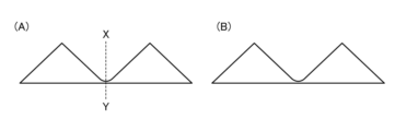
- the shapes shown in FIGS. 17A and 17B ((B) is a view of the shape seen from the XY cross-sectional direction of (A)) (a regular quadrangular pyramid of the same shape as in Example 1)
- Example 11 the same method as in Example 10 was used, and as shown in Table 7, the line speed among the molding conditions was changed to 15 m/min and 13 m/min, respectively. A diffusion sheet was produced.
Landscapes
- Physics & Mathematics (AREA)
- Engineering & Computer Science (AREA)
- Mechanical Engineering (AREA)
- Manufacturing & Machinery (AREA)
- Chemical & Material Sciences (AREA)
- General Physics & Mathematics (AREA)
- Optics & Photonics (AREA)
- Nonlinear Science (AREA)
- Health & Medical Sciences (AREA)
- General Engineering & Computer Science (AREA)
- Crystallography & Structural Chemistry (AREA)
- Mathematical Physics (AREA)
- Ophthalmology & Optometry (AREA)
- Materials Engineering (AREA)
- Polymers & Plastics (AREA)
- Organic Chemistry (AREA)
- Medicinal Chemistry (AREA)
- Chemical Kinetics & Catalysis (AREA)
- Thermal Sciences (AREA)
- Optical Elements Other Than Lenses (AREA)
- Planar Illumination Modules (AREA)
- Liquid Crystal (AREA)
- Extrusion Moulding Of Plastics Or The Like (AREA)
Abstract
Description

以下、本開示の実施形態について、図面を参照しながら説明する。尚、本開示の範囲は、以下の実施形態に限定されず、本開示の技術的思想の範囲内で任意に変更可能である。
図1に示すように、本実施形態の液晶表示装置50は、液晶表示パネル5と、液晶表示パネル5の下面に貼付された第1偏光板6と、液晶表示パネル5の上面に貼付された第2偏光板7と、液晶表示パネル5の背面側に第1偏光板6を介して設けられたバックライトユニット40とを備えている。液晶表示パネル5は、互いに対向するように設けられたTFT基板1及びCF基板2と、TFT基板1とCF基板2との間に設けられた液晶層3と、TFT基板1とCF基板2との間に液晶層3を封入するために枠状に設けられたシール材(図示省略)とを備える。
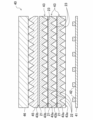
図2に示すように、本実施形態のバックライトユニット40は、反射シート41と、反射シート41上に2次元状に配置された複数の小型光源42と、複数の小型光源42の上側に設けられた第1光拡散シート43の積層体と、第1光拡散シート43の積層体の上側に設けられた第2光拡散シート44と、第2光拡散シート44の上側に順に設けられた第1プリズムシート45及び第2プリズムシート46とを備える。本例では、第1光拡散シート43の積層体は、同じ構造の第1光拡散シート43が2層積層されて構成される。図示は省略しているが、第2プリズムシート46の上側に偏光シートが設けられてもよい。
図2に示す例では、第1光拡散シート43の第1面(小型光源42と対向する面)43aに複数の凹部22を形成したが、これに代えて、或いは、これに加えて、第1光拡散シート43の第2面43bに、凹部22と同様の他の凹部を複数形成してもよい。
第1光拡散シート43のマトリックス樹脂としては、例えば、下記式(1)で表されるジヒドロキシ化合物に由来する第1構造単位から構成される単独重合ポリカーボネート樹脂を用いてもよい。




以下、第1光拡散シート43の製造方法について説明する。第1光拡散シート43の製造方法は、特に限定されないが、例えば、押出成形法、射出成形法などを用いてもよい。第1光拡散シート43を押出成形する場合、例えば、ライン速度を10m/分以上30m/分以下、圧縮線圧力を100kgf/cm以上500kgf/cm以下に設定してもよい。
以下、本実施形態の第1光拡散シート43の特徴について、図5~図10を参照しながら詳細に説明する。
以上に説明したように、本実施形態の第1光拡散シート43は、「上記式(1)で表されるジヒドロキシ化合物に由来する第1構造単位から構成される単独重合ポリカーボネート樹脂」、又は、「前記第1構造単位と、脂肪族ジヒドロキシ化合物、脂環式ジヒドロキシ化合物、及びエーテル基含有ジヒドロキシ化合物(上記式(1)で表されるジヒドロキシ化合物を除く)からなる群より選ばれる1種以上の他のジヒドロキシ化合物に由来する第2構造単位とから構成される共重合ポリカーボネート樹脂」を含む。
以下、実施例に係る第1光拡散シート43について、比較例と対照しながら説明する。
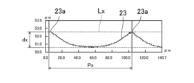
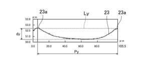
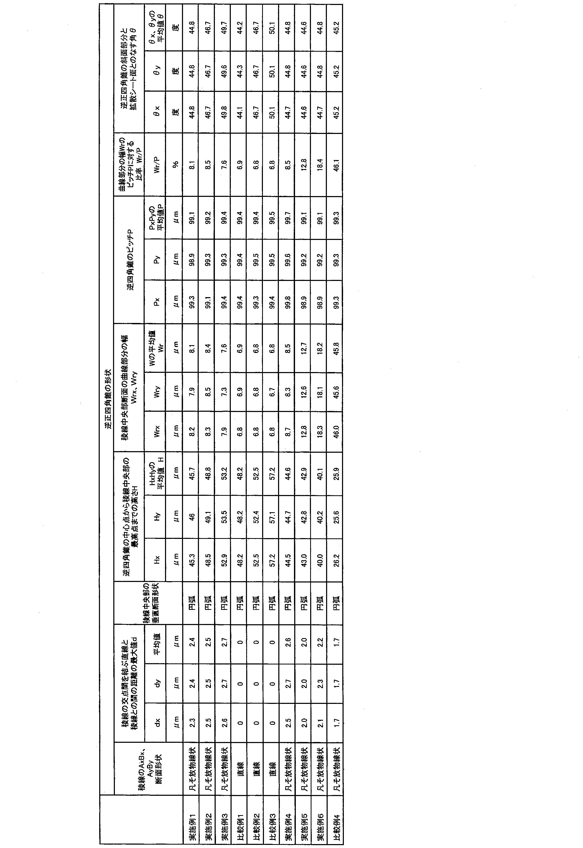
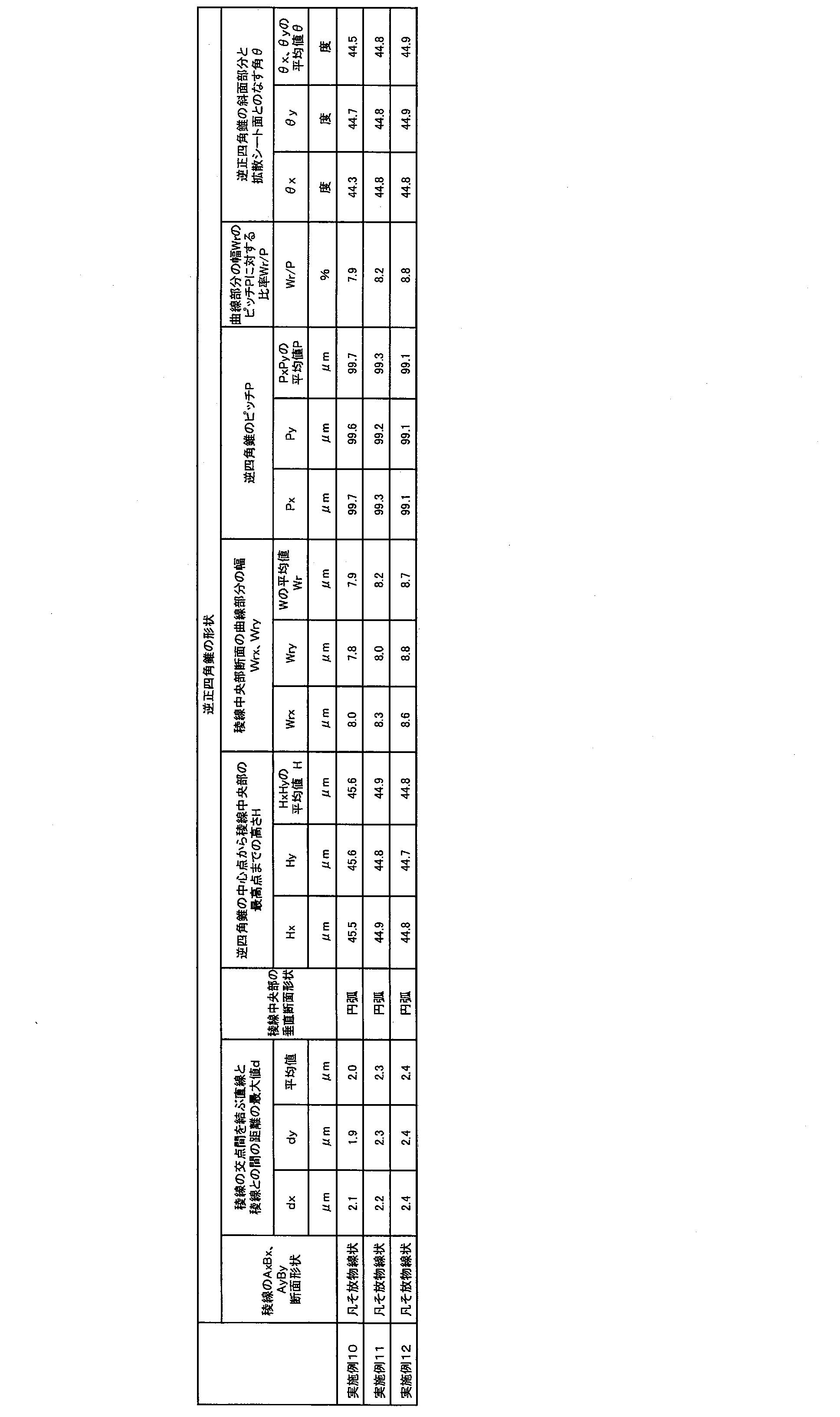
後述する各実施例の第1光拡散シート43に形成された凹部22の形状観察は、キーエンス社製のレーザーマイクロスコープVK-100を使用して行った。具体的には、逆正四角錐に形成された凹部22の稜線23の断面形状(図6、図7、図9、図10に示す断面形状)、図6、図7に示す最大高低差dx、dy(交点23a間を結ぶ直線と稜線23との距離の最大値)とその平均値d、図9、図10に示す高さHx、Hy(凹部22の中心22aから稜線23の頂点までの高さ)とその平均値H、図9、図10に示す寸法Wrx、Wry(X方向、Y方向において稜線23の頂部の曲線部分が占める寸法)とその平均値Wr、図6、図7に示す凹部22の配列ピッチPx、Py(X方向、Y方向における交点23a同士の水平距離)とその平均値P、配列ピッチPに対する寸法Wrの比率Wr/P(単位:%)、及び、図9、図10に示す角度θx、θy(X方向、Y方向において凹部22の壁面(逆正四角錐の斜面)と第1光拡散シート43のシート面とがなす角度)の測定を行った。
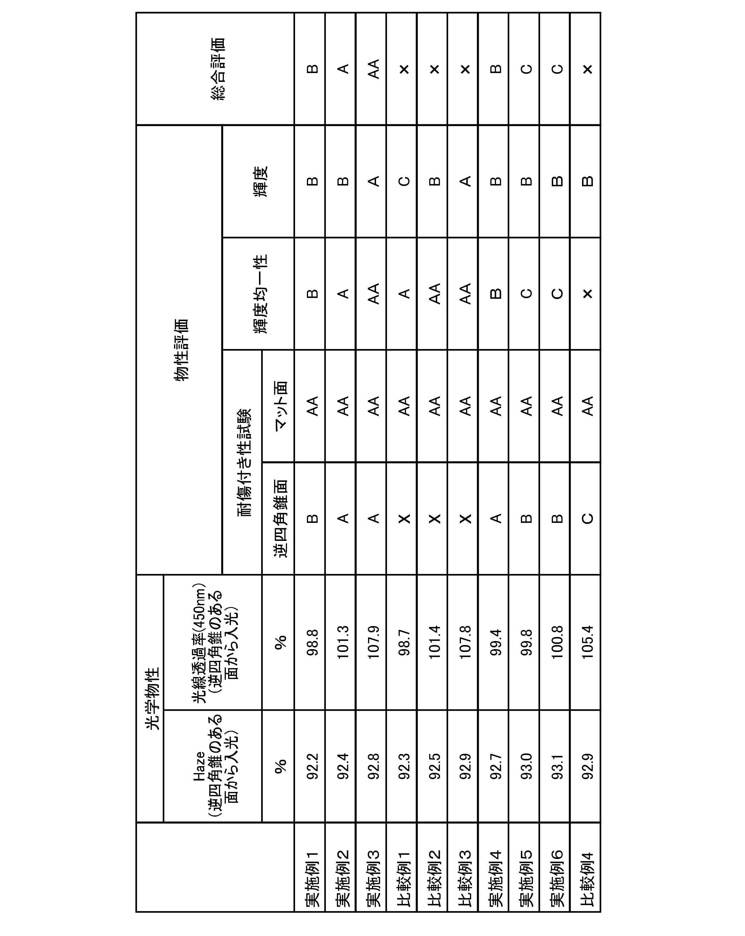
後述する各実施例の第1光拡散シート43の光学物性として、Haze(ヘーズ)、及び波長450nmにおける光線透過率を測定した。Hazeは、JIS K-7105に準拠して、スガ試験機株式会社製のHZ-2を用いて、逆正四角錐に形成された凹部22の有る面(第1面43a)から光を入射させて測定した。また、波長450nmにおける光線透過率は、日本分光株式会社製のV-670を用いて、逆正四角錐に形成された凹部22の有る面(第1面43a)から光を入射させて測定した。
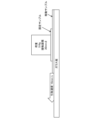
後述する各実施例の第1光拡散シート43の耐傷付き性試験には、図15に示した装置を用いた。図15に示すように、固定サンプルとなる第1光拡散シート43の下面を第1面43a(逆正四角錐形状の凹部22が形成された面)にし、移動サンプルとなる第1光拡散シート43の上面を第2面43b(マット面)にして、ガラス板上に移動サンプル及び固定サンプルを順次積層し、上方から、直径20mmの円形の面積に荷重516gfの重りを載せて、引取速度10mm/秒の速さで移動サンプルを引き取りながら100mm移動させて、移動サンプルと固定サンプルとの摩擦面の傷付き度合を目視で検査、判定した。検査、判定は、固定サンプルの下面(逆正四角錐の凹部22の形成面)、及び移動サンプルの上面(マット面)の両方について行った。
AA:目視では傷付きが全く見えず、耐傷付き性に大変優れた光拡散シートである。
A :目視では傷付きが殆ど見えず、耐傷付き性のかなり優れた光拡散シートである。
B :目視で傷付きがわずかに見え、耐傷付き性がある程度優れた光拡散シートである。
C :目視で傷つきが少し見え、耐傷付き性が何とか許される下限近くである光拡散シートである。
× :目視でも傷付きがはっきり多く見え、耐傷付き性の劣る光拡散シートである。
後述する各実施例の第1光拡散シート43の輝度及び輝度均一性の測定は、図2及び図3に示すバックライトユニット40の構成で実施した。すなわち、アレイ状に配列された小型光源42(LEDアレイ)の上に、後述する実施例で得られた逆正四角錐形状の凹部22を有する第1光拡散シート43を、凹部22が形成された第1面43aを光源42側に向けて2枚重ねて配置した。第1光拡散シート43の積層体の上には、ISO1133に準拠して測定したメルトマスフローレイトが15g/10分である芳香族ポリカーボネート樹脂99質量部に対して、拡散剤としてシリコーン複合パウダー(平均粒子径2.0μm)1質量部を配合した厚さ120μmの第2光拡散シート44を1枚、鏡面である第2面44bを光源42側に向けて重ねて配置した。第2光拡散シート44の製造では、一方のロールに鏡面ロールを用い、他方のロールに後述の実施例1と同じランダムなマット形状(表面粗さRa=2.5μm)を表面に持ったロールを用いて、実施例1と同じ方法で作成した。第2光拡散シート44においては、マット面(第1面44a)側の表面粗さRaが1.6μm、鏡面(第2面44b)側の表面粗さRaが0.4μmであった。第2光拡散シート44の上には、2枚のプリズムシート45、46を重ねて配置した。以上の構成で輝度及び輝度均一性の測定を行った。尚、LEDアレイとしては、LEDピッチ3mmのものを使用し、LED(小型光源42)としては、Cree社製の青色LED(品番XPGDRY-L1-0000-00501)を使用した。
輝度均一性=(断面輝度の平均値)÷(断面輝度の標準偏差)
の計算式に従って、輝度均一性を求めた。このようにして求められた輝度均一性の数値が高いほど、輝度が均一であることを示す。
AA:輝度均一性が210以上で、目視で輝度ムラが全く見えないレベルで、最も優れた均一性を示す光拡散シートである。
A :輝度均一性が200以上210未満で、目視で輝度斑は殆ど見えない、優れた均一性を示す光拡散シートである。
B :輝度均一性が190以上200未満で、目視で輝度斑がわずかに見えるが、合格レベルの均一性を示す光拡散シートである。
C :輝度均一性が180以上190未満で、目視で輝度斑が見えるが、合格レベル最低限の均一性を示す光拡散シートである。
X :輝度均一性が180未満で、目視で輝度斑がはっきり見える、均一性に劣る光拡散シートである。
A:断面輝度の平均値が3150cd/m2 以上の光拡散シートである。
B:断面輝度の平均値が3100cd/m2 以上3150cd/m2 未満の光拡散シートである。
C:断面輝度の平均値が3050cd/m2 以上3100cd/m2 未満の光拡散シートである。
後述する各実施例の第1光拡散シート43の総合評価は、耐傷付き性試験の結果、及び輝度均一性の評価結果に基づいて、以下の基準で行った。
AA:逆正四角錐面及びマット面の両方の耐傷付き性試験の評価結果と、輝度均一性の評価結果において、全てA以上であり且つ2つ以上AAがある総合的に最も優れた光拡散シートである。
A :逆正四角錐面及びマット面の両方の耐傷付き性試験の評価結果と、輝度均一性の評価結果において、全てA以上である総合的に最も優れた光拡散シート(ただしAA評価品を除く)である。
B :逆正四角錐面及びマット面の両方の耐傷付き性試験の評価結果と、輝度均一性の評価結果において、全てB以上である総合的に優れた光拡散シート(ただしAA、A評価品を除く)である。
C :逆正四角錐面及びマット面の両方の耐傷付き性試験の評価結果と、輝度均一性の評価結果において、全てC以上である総合的に最低限度以上の性能を有する使用可能な光拡散シート(ただしAA、A、B評価品を除く)である。
× :逆正四角錐面及びマット面の両方の耐傷付き性試験の評価結果と、輝度均一性の評価結果において、どれか1つ以上に×評価がある総合的に劣った光拡散シートである。
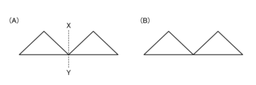
実施例1の第1光拡散シート43の製造方法は、以下の通りである。まず、ISO1133に準拠して測定したメルトマスフローレイトが10g/10分であるポリカーボネート樹脂(三菱ケミカル社製の植物由来のイソソルバイドが主原料であるバイオエンジニアリングプラスチックDURABIO(登録商標)D7340A)を押出機に投入して、溶融混錬してからT-ダイより樹脂を押し出す。その後、2本の金属ロールのうち一方のロールとして、図16の(A)、(B)((B)は(A)のX-Y線断面方向から見た形状図)に示した形状(高さ50μm、ピッチ100μmで頂角90度の正四角錐のピラミッド形状)を表面に持ったロールを使用し、他方のロールとして、ランダムなマット形状(表面粗さRa=2.5μm)を表面に持ったロールを使用し、T-ダイより押し出された溶融樹脂を当該2つのロールで挟んで形状転写しながら冷却する。これにより、表1に示すように、ロール上の正四角錐の高さに依存した深さの凹(逆)ピラミッド形状を1つの表面に持ち、表面粗さRa=1.68μmのマット面を別の表面に持つ厚さ180μmの単層の光拡散シートを押出成形法によって作成した。尚、成形条件としては、表1に示すように、ライン速度が15m/分、2つのロール間の圧縮力(圧縮線圧力)が250kgf/cmとなるように加圧を行い、ポリカーボネート樹脂への形状転写が良好で、且つロールからのシートの剥離が良好な樹脂温度条件(220~260℃)において光拡散シートを得た。
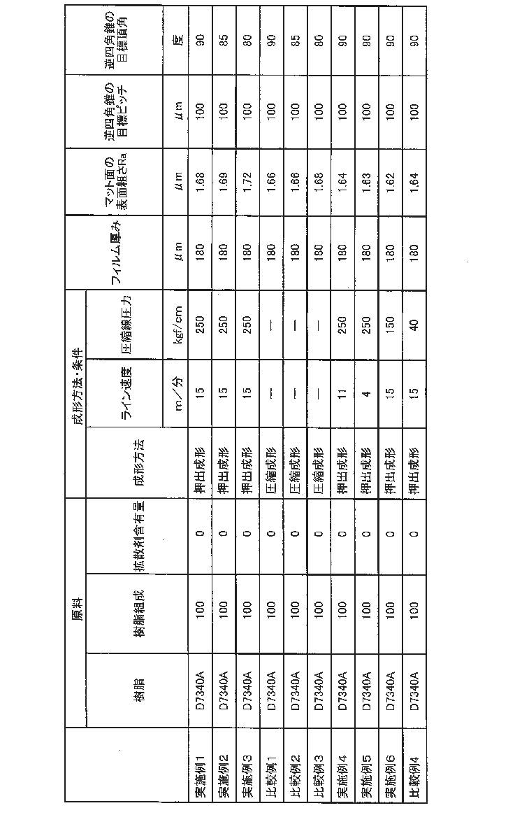
実施例2の第1光拡散シート43の製造方法では、2本の金属ロールのうち正四角錐形状のロールとして、高さ54.6μm、ピッチ100μmで頂角が85度の正四角錐のピラミッド形状を表面に持ったロールを使用した点を除いて、表1に示すように、実施例1と同じ条件を用いた。
比較例1では、まず、実施例1と同じポリカーボネート樹脂(DURABIO(登録商標) D7340A)を用いて、厚さ1mmのプレス原板を作った。続いて、図17の(A)、(B)((B)は(A)のX-Y線断面方向から見た形状図)に示した形状(実施例1と同じ形状の正四角錐のピラミッド形状においてピラミッドの谷部分を曲率半径4.2μmの曲面形状に丸めた形状)を表面に持った平板金型と、実施例1と同程度のランダムなマット形状(表面粗さRa=2μm)を表面に持った平板金型とを使用し、2枚の金型でプレス原板を挟んで、加熱冷却装置の付いたプレス機に入れて、プレス板温度240℃、面圧200kg/cm2の条件で20分間プレスした。その後、加圧したままでプレス板温度を20℃まで冷却して、樹脂板が十分冷却されるまで加圧保持し、表1に示す厚さ180μmの光拡散シートを圧縮成形法によって作成した。
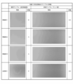
実施例1~3で得られた第1光拡散シート43について、測定で得られた各要素の形状、寸法及び角度などを比較例1~3と合わせて表2に示し、光学物性の測定結果、耐傷付き性試験の結果、輝度及び輝度均一性の評価結果、並びに総合評価結果を比較例1~3と合わせて表3に示す。また、実施例1~3、及び比較例1のそれぞれにおける耐傷つき性試験後のサンプル、具体的には、固定サンプル下面(逆四角錐面)、及び移動サンプル上面(マット面)の表面写真を図18に示す。
実施例4、5では、表1に示すように、成形条件のうちライン速度をそれぞれ11m/分、4m/分に変更した点を除いて、実施例1と同じ方法で光拡散シートを作製した。
実施例4~6で得られた第1光拡散シート43について、測定で得られた各要素の形状、寸法及び角度などを比較例4と合わせて表2に示し、光学物性の測定結果、耐傷付き性試験の結果、輝度及び輝度均一性の評価結果、並びに総合評価結果を比較例4と合わせて表3に示す。
実施例7の第1光拡散シート43の製造方法では、2本の金属ロールのうち正四角錐形状のロールとして、高さ90.0μm、ピッチ180μmで頂角が90度の正四角錐のピラミッド形状を表面に持ったロールを使用した点を除いて、実施例1とほぼ同じ条件を用いて、表4に示す厚さ200μmの光拡散シートを作製した。

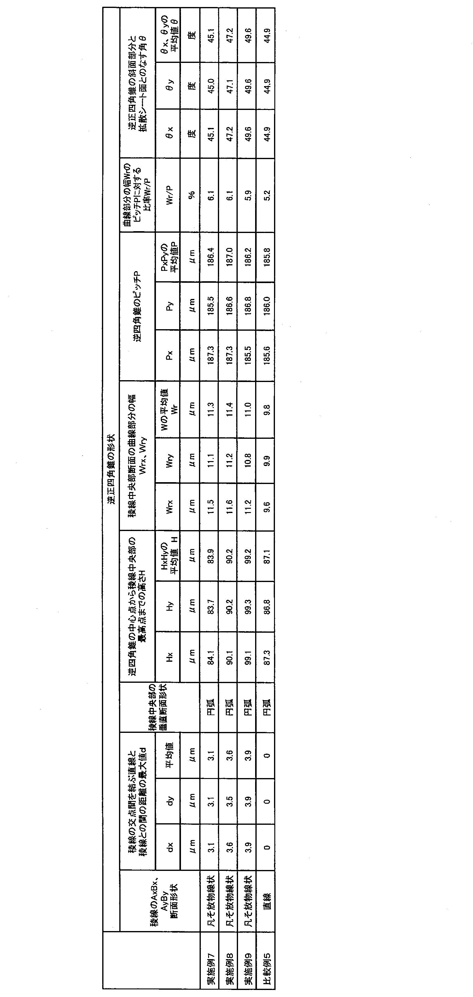
実施例7~9で得られた第1光拡散シート43について、測定で得られた各要素の形状、寸法及び角度などを比較例5と合わせて表5に示し、光学物性の測定結果、耐傷付き性試験の結果、輝度及び輝度均一性の評価結果、並びに総合評価結果を比較例5と合わせて表6に示す。

実施例10においては、ISO1133に準拠して測定したメルトマスフローレイトが5g/10分であるポリカーボネート樹脂(三菱ケミカル社製の植物由来のイソソルバイドが主原料であるバイオエンジニアリングプラスチックDURABIO(登録商標) D5380A)を用いて、ポリカーボネート樹脂99質量部に対して、拡散剤としてシリコーン複合パウダー(平均粒子径2.0μm)1質量部をあらかじめ混合したものを押出機に投入して溶融混錬を行う点を除いて、実施例1と同じ2本のロールを用いると共に、表7に示すように、ライン速度が17m/分、2つのロール間の圧縮力(圧縮線圧力)が280kgf/cmとなるように加圧を行い、ポリカーボネート樹脂への形状転写が良好で、且つロールからのシートの剥離が良好な樹脂温度条件(220~260℃)において厚さ180μmの光拡散シートを得た。
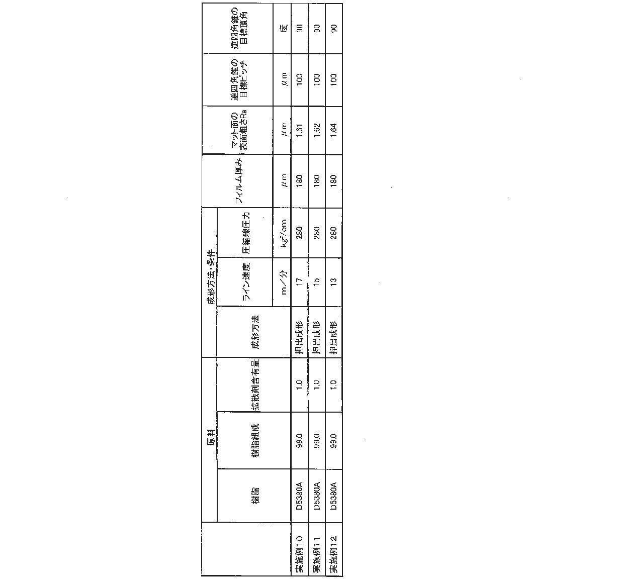
実施例10~12で得られた第1光拡散シート43について、測定で得られた各要素の形状、寸法及び角度などを表8に示し、光学物性の測定結果、耐傷付き性試験の結果、輝度及び輝度均一性の評価結果、並びに総合評価結果を表9に示す。

以上、本開示についての実施形態(実施例を含む。以下同じ。)を説明したが、本開示は前述の実施形態のみに限定されず、開示の範囲内で種々の変更が可能である。すなわち、前述の実施形態の説明は、本質的に例示に過ぎず、本開示、その適用物或いはその用途を制限することを意図するものではない。例えば、光拡散シートの構成(層構造、材質等)は、前述の実施形態の第1光拡散シート43の構成に限定されないことは言うまでもない。また、光拡散シートが適用されるバックライトや、当該バックライトを備えた液晶表示装置の構成も、前述の実施形態のバックライトユニット40や液晶表示装置50の構成に限定されないことは言うまでもない。
2 CF基板
3 液晶層
5 液晶表示パネル
6 第1偏光板
7 第2偏光板
21 基材層
22 凹部
22a 中心
23 稜線
23a 交点
23b 最下点
40 バックライトユニット
41 反射シート
42 小型光源
43 第1光拡散シート
43a 第1面
43b 第2面
44 第2光拡散シート
44a 第1面
44b 第2面
45 第1プリズムシート
46 第2プリズムシート
50 液晶表示装置
50a 表示画面
Claims (17)
- 略逆多角錐又は略逆多角錐台形に形成された複数の凹部を少なくとも第1面に有する光拡散シートであって、
下記式(1)で表されるジヒドロキシ化合物に由来する第1構造単位から構成される単独重合ポリカーボネート樹脂、又は
前記第1構造単位と、脂肪族ジヒドロキシ化合物、脂環式ジヒドロキシ化合物、及びエーテル基含有ジヒドロキシ化合物(下記式(1)で表されるジヒドロキシ化合物を除く)からなる群より選ばれる1種以上のジヒドロキシ化合物に由来する第2構造単位とから構成される共重合ポリカーボネート樹脂
を含み、
前記複数の凹部を区画する稜線は、当該稜線の交点同士を結ぶ直線に対して、当該交点間において凹んだ形状を有し、
前記複数の凹部の配列ピッチをPとし、前記複数の凹部の配列方向において前記稜線の頂部の曲線部分が占める寸法をWrとすると、比率Wr/Pは、0.3以下であり、
前記直線と前記稜線との最大高低差dは、1μm以上10μm以下である、
光拡散シート。

- 前記最大高低差dは、1.5μm以上7μm以下である
請求項1に記載の光拡散シート。 - 前記最大高低差dは、2.5μm以上5μm以下である
請求項2に記載の光拡散シート。 - 前記比率Wr/Pは、0.2以下である、
請求項1~3のいずれか1項に記載の光拡散シート。 - 前記比率Wr/Pは、0.1以下である、
請求項4に記載の光拡散シート。 - 前記配列ピッチPは、50μm以上500μm以下であり、
前記複数の凹部の壁面が前記光拡散シートのシート面となす角度は、40度以上65度以下である、
請求項1~3のいずれか1項に記載の光拡散シート。 - 前記稜線は、前記交点間において略放物線状、略円弧状、略三角形状又は略台形状に凹んでいる、
請求項1~3のいずれか1項に記載の光拡散シート。 - 前記複数の凹部は、略逆四角錐又は略逆四角錐台形に形成され、
前記稜線は、第1方向及び第2方向に延び、
前記最大高低差dは、前記第1方向における前記直線と前記稜線との最大高低差dxと、前記第2方向における前記直線と前記稜線との最大高低差dyとの平均値であり、
前記配列ピッチPは、前記第1方向における前記複数の凹部の配列ピッチPxと、前記第2方向における前記複数の凹部の配列ピッチPyとの平均値であり、
前記寸法Wrは、前記第1方向において前記稜線の頂部の曲線部分が占める寸法Wrxと、前記第2方向において前記稜線の頂部の曲線部分が占める寸法Wryとの平均値である、
請求項1~3のいずれか1項に記載の光拡散シート。 - 前記複数の凹部は、前記第1面のみに設けられ、
第2面は、マット面である、
請求項1~3のいずれか1項に記載の光拡散シート。 - 液晶表示装置に組み込まれ、光源から発せられた光を表示画面の方に導くバックライトユニットであって、
前記表示画面と前記光源との間に、請求項1~3のいずれか1項に記載の光拡散シートを備える、
バックライトユニット。 - 前記光源は、前記光拡散シートから見て前記表示画面の反対側に設けられた反射シートの上に配置される、
請求項10に記載のバックライトユニット。 - 前記光拡散シートは、複数枚積層して前記表示画面と前記光源との間に配置される
請求項10に記載のバックライトユニット。 - 前記光拡散シートは、3枚以上積層して前記表示画面と前記光源との間に配置される
請求項12に記載のバックライトユニット。 - 3枚以上積層された前記光拡散シートのうち、前記表示画面に最も近い光拡散シートは、拡散剤を含有し、その他の光拡散シートは、実質的に拡散剤を含有しない
請求項13に記載のバックライトユニット。 - 請求項10に記載のバックライトユニットと、
液晶表示パネルとを備える、
液晶表示装置。 - 請求項15に記載の液晶表示装置を備える、
情報機器。 - 請求項1~3のいずれか1項に記載の光拡散シートの製造方法であって、
ライン速度が10m/分以上30m/分以下、圧縮線圧力が100kgf/cm以上500kgf/cm以下で前記光拡散シートを押出成形する、
光拡散シートの製造方法。
Priority Applications (4)
| Application Number | Priority Date | Filing Date | Title |
|---|---|---|---|
| CN202280064037.3A CN117999500A (zh) | 2021-11-02 | 2022-10-31 | 光漫射片、背光单元、液晶显示装置、信息设备及光漫射片的制造方法 |
| EP22889943.1A EP4411434B1 (en) | 2021-11-02 | 2022-10-31 | Light diffusion sheet, backlight unit, liquid crystal display device, information apparatus, and method for manufacturing light diffusion sheet |
| KR1020247009388A KR20240045329A (ko) | 2021-11-02 | 2022-10-31 | 광확산 시트, 백라이트 유닛, 액정표시장치, 정보기기, 및 광확산 시트의 제조방법 |
| US18/652,702 US20240345294A1 (en) | 2021-11-02 | 2024-05-01 | Light diffusion sheet, backlight unit, liquid crystal display device, information apparatus, and method for manufacturing light diffusion sheet |
Applications Claiming Priority (4)
| Application Number | Priority Date | Filing Date | Title |
|---|---|---|---|
| JP2021-179472 | 2021-11-02 | ||
| JP2021179472 | 2021-11-02 | ||
| JP2022063753A JP7503091B2 (ja) | 2021-11-02 | 2022-04-07 | 光拡散シート、バックライトユニット、液晶表示装置、情報機器、及び光拡散シートの製造方法 |
| JP2022-063753 | 2022-04-07 |
Related Child Applications (1)
| Application Number | Title | Priority Date | Filing Date |
|---|---|---|---|
| US18/652,702 Continuation US20240345294A1 (en) | 2021-11-02 | 2024-05-01 | Light diffusion sheet, backlight unit, liquid crystal display device, information apparatus, and method for manufacturing light diffusion sheet |
Publications (1)
| Publication Number | Publication Date |
|---|---|
| WO2023080123A1 true WO2023080123A1 (ja) | 2023-05-11 |
Family
ID=86241097
Family Applications (1)
| Application Number | Title | Priority Date | Filing Date |
|---|---|---|---|
| PCT/JP2022/040810 Ceased WO2023080123A1 (ja) | 2021-11-02 | 2022-10-31 | 光拡散シート、バックライトユニット、液晶表示装置、情報機器、及び光拡散シートの製造方法 |
Country Status (7)
| Country | Link |
|---|---|
| US (1) | US20240345294A1 (ja) |
| EP (1) | EP4411434B1 (ja) |
| JP (2) | JP7503091B2 (ja) |
| KR (1) | KR20240045329A (ja) |
| CN (1) | CN117999500A (ja) |
| TW (1) | TWI856389B (ja) |
| WO (1) | WO2023080123A1 (ja) |
Citations (13)
| Publication number | Priority date | Publication date | Assignee | Title |
|---|---|---|---|---|
| JP2004538506A (ja) * | 2001-08-03 | 2004-12-24 | スリーエム イノベイティブ プロパティズ カンパニー | 微細複製構造を有する光学フィルム |
| US20070188861A1 (en) * | 2006-02-10 | 2007-08-16 | Samsung Electronics Co., Ltd. | Optical sheet and display device having the same |
| JP2009048995A (ja) * | 2007-07-24 | 2009-03-05 | Sony Corp | 光学フィルム、照明装置および表示装置 |
| JP2010117707A (ja) | 2008-10-16 | 2010-05-27 | Asahi Kasei E-Materials Corp | 光拡散板及び直下型点光源バックライト装置 |
| JP2010160438A (ja) * | 2009-01-09 | 2010-07-22 | Toppan Printing Co Ltd | レンズシート、バックライトユニット及びディスプレイ装置 |
| JP2010160437A (ja) * | 2009-01-09 | 2010-07-22 | Toppan Printing Co Ltd | 光学シート、バックライト・ユニット及びディスプレイ装置 |
| JP2011043800A (ja) * | 2009-07-21 | 2011-03-03 | Sumitomo Chemical Co Ltd | 液晶パネルおよびこれを用いた液晶表示装置 |
| JP2011227231A (ja) * | 2010-04-19 | 2011-11-10 | Toppan Printing Co Ltd | 光学シート、光学シート組合せ体、バックライトユニット及びディスプレイ装置 |
| JP2012047912A (ja) * | 2010-08-25 | 2012-03-08 | Dainippon Printing Co Ltd | プリズムシート、面光源装置及び液晶表示装置 |
| US8270082B2 (en) * | 2009-06-16 | 2012-09-18 | Entire Technology Co., Ltd. | Microstructure diffuser |
| JP2013072940A (ja) * | 2011-09-27 | 2013-04-22 | Dainippon Printing Co Ltd | 光学シート、面光源装置及び液晶表示装置 |
| JP2013225058A (ja) * | 2012-04-23 | 2013-10-31 | Asahi Kasei E-Materials Corp | 光学板及び直下型点光源バックライト装置 |
| WO2016171194A1 (ja) * | 2015-04-21 | 2016-10-27 | 三菱化学株式会社 | ポリカーボネート樹脂フィルム |
Family Cites Families (14)
| Publication number | Priority date | Publication date | Assignee | Title |
|---|---|---|---|---|
| US20090021667A1 (en) * | 2005-04-12 | 2009-01-22 | Toru Horiguchi | Resin Sheet, Direct Backlight Unit, and Direct Backlight Type Liquid Crystal Display |
| JP2007178875A (ja) * | 2005-12-28 | 2007-07-12 | Takiron Co Ltd | 光拡散シート |
| JP5019746B2 (ja) * | 2005-12-28 | 2012-09-05 | タキロン株式会社 | 直下ライト方式のバックライトユニット |
| JP5532531B2 (ja) * | 2006-06-19 | 2014-06-25 | 三菱化学株式会社 | ポリカーボネート共重合体及びその製造方法 |
| TWI365305B (en) * | 2008-06-20 | 2012-06-01 | Coretronic Corp | Backlight module |
| KR20100054700A (ko) * | 2008-11-14 | 2010-05-25 | 엘지디스플레이 주식회사 | 백라이트 유닛 |
| JP6108651B2 (ja) * | 2008-11-28 | 2017-04-05 | 三菱化学株式会社 | ポリカーボネート樹脂組成物、光学フィルム及びポリカーボネート樹脂成形品 |
| JP6203513B2 (ja) * | 2013-03-28 | 2017-09-27 | 恵和株式会社 | ライトガイドフィルム、バックライトユニット、携帯型コンピュータ及びライトガイドフィルムの製造方法 |
| JP5767419B1 (ja) * | 2014-02-19 | 2015-08-19 | 恵和株式会社 | 導光シート、バックライトユニット及び携帯型端末 |
| JP5767418B1 (ja) * | 2014-02-19 | 2015-08-19 | 恵和株式会社 | 導光シート、バックライトユニット及び携帯型端末 |
| EP3050915A1 (en) * | 2015-01-27 | 2016-08-03 | Keiwa Inc. | Glass plate substitute film, and display device |
| JPWO2017014051A1 (ja) * | 2015-07-23 | 2018-05-10 | 恵和株式会社 | 積層シート、液晶表示モジュール、バックライトユニット及び積層シートの製造方法 |
| JP2018147759A (ja) * | 2017-03-06 | 2018-09-20 | 恵和株式会社 | 光学シート及びバックライトユニット |
| JP6886992B2 (ja) * | 2018-03-30 | 2021-06-16 | 恵和株式会社 | 光拡散板積層体、バックライトユニット、及び液晶表示装置 |
-
2022
- 2022-04-07 JP JP2022063753A patent/JP7503091B2/ja active Active
- 2022-10-12 TW TW111138519A patent/TWI856389B/zh active
- 2022-10-31 EP EP22889943.1A patent/EP4411434B1/en active Active
- 2022-10-31 WO PCT/JP2022/040810 patent/WO2023080123A1/ja not_active Ceased
- 2022-10-31 CN CN202280064037.3A patent/CN117999500A/zh active Pending
- 2022-10-31 KR KR1020247009388A patent/KR20240045329A/ko active Pending
-
2024
- 2024-04-26 JP JP2024072349A patent/JP7688196B2/ja active Active
- 2024-05-01 US US18/652,702 patent/US20240345294A1/en active Pending
Patent Citations (13)
| Publication number | Priority date | Publication date | Assignee | Title |
|---|---|---|---|---|
| JP2004538506A (ja) * | 2001-08-03 | 2004-12-24 | スリーエム イノベイティブ プロパティズ カンパニー | 微細複製構造を有する光学フィルム |
| US20070188861A1 (en) * | 2006-02-10 | 2007-08-16 | Samsung Electronics Co., Ltd. | Optical sheet and display device having the same |
| JP2009048995A (ja) * | 2007-07-24 | 2009-03-05 | Sony Corp | 光学フィルム、照明装置および表示装置 |
| JP2010117707A (ja) | 2008-10-16 | 2010-05-27 | Asahi Kasei E-Materials Corp | 光拡散板及び直下型点光源バックライト装置 |
| JP2010160438A (ja) * | 2009-01-09 | 2010-07-22 | Toppan Printing Co Ltd | レンズシート、バックライトユニット及びディスプレイ装置 |
| JP2010160437A (ja) * | 2009-01-09 | 2010-07-22 | Toppan Printing Co Ltd | 光学シート、バックライト・ユニット及びディスプレイ装置 |
| US8270082B2 (en) * | 2009-06-16 | 2012-09-18 | Entire Technology Co., Ltd. | Microstructure diffuser |
| JP2011043800A (ja) * | 2009-07-21 | 2011-03-03 | Sumitomo Chemical Co Ltd | 液晶パネルおよびこれを用いた液晶表示装置 |
| JP2011227231A (ja) * | 2010-04-19 | 2011-11-10 | Toppan Printing Co Ltd | 光学シート、光学シート組合せ体、バックライトユニット及びディスプレイ装置 |
| JP2012047912A (ja) * | 2010-08-25 | 2012-03-08 | Dainippon Printing Co Ltd | プリズムシート、面光源装置及び液晶表示装置 |
| JP2013072940A (ja) * | 2011-09-27 | 2013-04-22 | Dainippon Printing Co Ltd | 光学シート、面光源装置及び液晶表示装置 |
| JP2013225058A (ja) * | 2012-04-23 | 2013-10-31 | Asahi Kasei E-Materials Corp | 光学板及び直下型点光源バックライト装置 |
| WO2016171194A1 (ja) * | 2015-04-21 | 2016-10-27 | 三菱化学株式会社 | ポリカーボネート樹脂フィルム |
Non-Patent Citations (1)
| Title |
|---|
| See also references of EP4411434A4 |
Also Published As
| Publication number | Publication date |
|---|---|
| JP7688196B2 (ja) | 2025-06-03 |
| TW202335830A (zh) | 2023-09-16 |
| KR20240045329A (ko) | 2024-04-05 |
| EP4411434A4 (en) | 2025-03-12 |
| JP2023068607A (ja) | 2023-05-17 |
| JP2024113691A (ja) | 2024-08-22 |
| TWI856389B (zh) | 2024-09-21 |
| EP4411434A1 (en) | 2024-08-07 |
| JP7503091B2 (ja) | 2024-06-19 |
| EP4411434B1 (en) | 2025-12-03 |
| CN117999500A (zh) | 2024-05-07 |
| US20240345294A1 (en) | 2024-10-17 |
Similar Documents
| Publication | Publication Date | Title |
|---|---|---|
| CN111656268B (zh) | 光学片、背光单元、液晶显示装置以及信息设备 | |
| KR102816325B1 (ko) | 광확산 시트, 백라이트 유닛, 액정 표시 장치, 정보 기기, 및 광확산 시트의 제조 방법 | |
| CN109387979B (zh) | 缓冲片及平板显示器 | |
| JP7368430B2 (ja) | 光拡散シート、バックライトユニット、液晶表示装置、情報機器、及び光拡散シートの製造方法 | |
| JP7688196B2 (ja) | 光拡散シート、バックライトユニット、液晶表示装置、情報機器、及び光拡散シートの製造方法 | |
| JP7389296B1 (ja) | 光拡散シート、バックライトユニット、液晶表示装置、情報機器、及び光拡散シートの製造方法 | |
| TWI685705B (zh) | 緩衝片及平板顯示器 | |
| JP7713991B2 (ja) | バックライトユニット、液晶表示装置、及び情報機器 | |
| WO2023162358A1 (ja) | 複合光拡散シート、バックライトユニット、液晶表示装置、及び情報機器 | |
| WO2023228684A1 (ja) | 光拡散シート、バックライトユニット、液晶表示装置、及び情報機器 | |
| JP2023110320A (ja) | 光学シート積層体、バックライトユニット、液晶表示装置、情報機器、及びバックライトユニットの製造方法 | |
| JP2023113017A (ja) | 光拡散シート、バックライトユニット、液晶表示装置及び情報機器 | |
| CN118265931A (zh) | 复合光漫射片、背光单元、液晶显示装置以及信息设备 |
Legal Events
| Date | Code | Title | Description |
|---|---|---|---|
| 121 | Ep: the epo has been informed by wipo that ep was designated in this application |
Ref document number: 22889943 Country of ref document: EP Kind code of ref document: A1 |
|
| WWE | Wipo information: entry into national phase |
Ref document number: 202280064037.3 Country of ref document: CN |
|
| WWE | Wipo information: entry into national phase |
Ref document number: 2022889943 Country of ref document: EP |
|
| ENP | Entry into the national phase |
Ref document number: 2022889943 Country of ref document: EP Effective date: 20240503 |
|
| NENP | Non-entry into the national phase |
Ref country code: DE |
|
| WWG | Wipo information: grant in national office |
Ref document number: 2022889943 Country of ref document: EP |