WO2023084898A1 - エレクトロスラグ再溶解法に用いられるフラックス、そのフラックスの製造方法および高純度鋼の製造方法 - Google Patents
エレクトロスラグ再溶解法に用いられるフラックス、そのフラックスの製造方法および高純度鋼の製造方法 Download PDFInfo
- Publication number
- WO2023084898A1 WO2023084898A1 PCT/JP2022/033883 JP2022033883W WO2023084898A1 WO 2023084898 A1 WO2023084898 A1 WO 2023084898A1 JP 2022033883 W JP2022033883 W JP 2022033883W WO 2023084898 A1 WO2023084898 A1 WO 2023084898A1
- Authority
- WO
- WIPO (PCT)
- Prior art keywords
- flux
- component
- mass
- cao
- less
- Prior art date
- Legal status (The legal status is an assumption and is not a legal conclusion. Google has not performed a legal analysis and makes no representation as to the accuracy of the status listed.)
- Ceased
Links
Images

Classifications
-
- C—CHEMISTRY; METALLURGY
- C22—METALLURGY; FERROUS OR NON-FERROUS ALLOYS; TREATMENT OF ALLOYS OR NON-FERROUS METALS
- C22B—PRODUCTION AND REFINING OF METALS; PRETREATMENT OF RAW MATERIALS
- C22B9/00—General processes of refining or remelting of metals; Apparatus for electroslag or arc remelting of metals
- C22B9/16—Remelting metals
- C22B9/18—Electroslag remelting
-
- C—CHEMISTRY; METALLURGY
- C21—METALLURGY OF IRON
- C21C—PROCESSING OF PIG-IRON, e.g. REFINING, MANUFACTURE OF WROUGHT-IRON OR STEEL; TREATMENT IN MOLTEN STATE OF FERROUS ALLOYS
- C21C5/00—Manufacture of carbon-steel, e.g. plain mild steel, medium carbon steel or cast steel or stainless steel
- C21C5/52—Manufacture of steel in electric furnaces
- C21C5/5211—Manufacture of steel in electric furnaces in an alternating current [AC] electric arc furnace
-
- C—CHEMISTRY; METALLURGY
- C21—METALLURGY OF IRON
- C21C—PROCESSING OF PIG-IRON, e.g. REFINING, MANUFACTURE OF WROUGHT-IRON OR STEEL; TREATMENT IN MOLTEN STATE OF FERROUS ALLOYS
- C21C5/00—Manufacture of carbon-steel, e.g. plain mild steel, medium carbon steel or cast steel or stainless steel
- C21C5/52—Manufacture of steel in electric furnaces
- C21C5/54—Processes yielding slags of special composition
-
- C—CHEMISTRY; METALLURGY
- C21—METALLURGY OF IRON
- C21C—PROCESSING OF PIG-IRON, e.g. REFINING, MANUFACTURE OF WROUGHT-IRON OR STEEL; TREATMENT IN MOLTEN STATE OF FERROUS ALLOYS
- C21C7/00—Treating molten ferrous alloys, e.g. steel, not covered by groups C21C1/00 - C21C5/00
- C21C7/04—Removing impurities by adding a treating agent
- C21C7/076—Use of slags or fluxes as treating agents
-
- C—CHEMISTRY; METALLURGY
- C22—METALLURGY; FERROUS OR NON-FERROUS ALLOYS; TREATMENT OF ALLOYS OR NON-FERROUS METALS
- C22B—PRODUCTION AND REFINING OF METALS; PRETREATMENT OF RAW MATERIALS
- C22B9/00—General processes of refining or remelting of metals; Apparatus for electroslag or arc remelting of metals
- C22B9/10—General processes of refining or remelting of metals; Apparatus for electroslag or arc remelting of metals with refining or fluxing agents; Use of materials therefor, e.g. slagging or scorifying agents
-
- Y—GENERAL TAGGING OF NEW TECHNOLOGICAL DEVELOPMENTS; GENERAL TAGGING OF CROSS-SECTIONAL TECHNOLOGIES SPANNING OVER SEVERAL SECTIONS OF THE IPC; TECHNICAL SUBJECTS COVERED BY FORMER USPC CROSS-REFERENCE ART COLLECTIONS [XRACs] AND DIGESTS
- Y02—TECHNOLOGIES OR APPLICATIONS FOR MITIGATION OR ADAPTATION AGAINST CLIMATE CHANGE
- Y02P—CLIMATE CHANGE MITIGATION TECHNOLOGIES IN THE PRODUCTION OR PROCESSING OF GOODS
- Y02P10/00—Technologies related to metal processing
- Y02P10/20—Recycling
Definitions
- the present invention relates to a flux used in electroslag remelting, a method for producing the flux, and a method for producing high-purity steel.
- the electroslag remelting method is a type of special melting method in which metal materials (such as steel) are melted and refined again to produce high-purity metals. This method is also called “ESR method”, “ESR process”, etc., taking the initials of Electro-Slag Remelting process in English (these notations are also used in this specification).
- the electrode metal is melted by the resistance heat of the slag, and (2) impurities (sulfur, oxygen, etc.) are removed when the droplets of the melted metal pass through the slag pool. , (3) and the molten metal solidifies at the bottom of the furnace to form an ingot, thereby purifying the metal material.
- slag containing CaF 2 , Al 2 O 3 and CaO as main components is often used. That is, solid flux mainly composed of CaF 2 , Al 2 O 3 and CaO is often melted at a high temperature to form slag.
- Patent Document 1 SiO 2 : 0.2 to 15% by weight, Al 2 O 3 : 12 to 40% by weight, alkaline earth metal oxides: 15 to 40% by weight, CaF 2 : 12 to 75%
- a slag for the electroslag remelting process is described with an analytical composition of weight % FeO: 0.5 weight % or less, MnO: 1 weight % or less, and TiO 2 : 10 weight % or less.
- the water content in the slag should be reduced in order to cause hydrogen embrittlement of metal materials to be refined by dissolving the water derived from the flux.
- the water content of slag and its change over time were measured by allowing magnesium perchlorate to absorb the water released by heating granular slag to 650°C. is stated.
- the composition of the flux to be added is CaO: 20 to 60 mass%, Al 2 O 3 : 10 to 40 mass%, CaF 2 : 20 to 60 mass%, iron oxide: 1 to 10 mass% and CaO/Al 2 O 3 : 1.0 to 6.0.
- An object of the present invention is to provide a flux used in an electroslag remelting method, which is capable of producing a high-purity metal with suppressed hydrogen embrittlement at a high yield while containing a highly hygroscopic CaO component.
- a flux used in the electroslag remelting method including a mixture of particles containing two components of CaF and particles containing three components of Al2O and CaO, W is the initial water content of the flux obtained by the Karl Fischer method, and the water content is represented by the difference between the water content W14 and the initial water content W when the flux is placed in an environment of 30 ° C. and 85% RH for 14 days.
- a flux is provided in which W is 0.05% by mass or less and ⁇ W is 0.03% by mass or less, where ⁇ W is the rate change.
- a method for producing the above flux a firing step of firing at least a compound containing two components of CaF to obtain particles containing two components of CaF; a melt-mixing step of melt-mixing at least a compound containing a CaO component and a compound containing an Al 2 O 3 component to obtain a molten mixture containing a CaO component and an Al 2 O 3 component; a pulverizing step of pulverizing the molten mixture containing the CaO component and the Al 2 O 3 component to obtain a pulverized product containing the CaO component and the Al 2 O 3 component;
- the pulverized material containing the CaO component and the Al 2 O 3 component is passed through a sieve with a nominal opening of 500 ⁇ m specified in JIS Z 8801-1: 2019.
- a method of making a flux comprising:
- a method for producing high-purity steel comprising a step of remelting raw material steel into high-purity steel by remelting using an electroslag remelting method, A method for producing high-purity steel is provided that uses the melt of the above flux as the molten slag.
- a flux for use in electroslag remelting is provided, which enables high-yield production of high-purity metal with suppressed hydrogen embrittlement.
- the term "slag” basically represents a state in which flux, which is solid at room temperature (25°C), is heated to a high temperature and melted. However, depending on the context, this is not the case (for example, in Patent Document 1, flux that is solid at room temperature seems to be expressed as "slag").
- the flux of this embodiment is used in the electroslag remelting method.
- This flux contains a mixture of particles containing two components of CaF and particles containing three components of Al 2 O and CaO.
- W is the water content of the flux), and the change in water content (moisture content after 14 days
- W is 0.05% by mass or less, preferably 0.03% by mass or less, more preferably 0.02% by mass or less, and still more preferably 0.015% by mass or less.
- ⁇ W is 0.03% by mass or less, preferably 0.01% by mass or less, more preferably 0.007% by mass or less, and still more preferably 0.005% by mass or less.
- the lower limit of W is ideally 0, but in reality it is, for example, 0.00001% by mass or more.
- the lower limit of ⁇ W is, for example, ⁇ 0.005% or more.
- the initial moisture content W and the change in moisture content ⁇ W at this time refer to the initial moisture content W and the change in moisture content ⁇ W in all particle sizes of the flux.
- Characteristics required for fluxes for ESR include low viscosity, high desulfurization, and high electrical resistance.
- the flux is composed of CaF 2 component, Al 2 O 3 component and CaO component.
- the CaO component used at this time has high hygroscopicity when present as a single CaO crystalline phase. Therefore, when the content of the CaO crystalline phase increases, the hygroscopicity of the flux deteriorates, and hydrogen embrittlement of the metal occurs. easier.
- the inventors In order to improve the yield of ingots obtained by the ESR method, the inventors particularly focused on the water content of the flux. Specifically, in order to accurately manage and optimize the water content of the flux, the inventors measured the water content by the Karl Fischer method, and the initial water content W obtained by the measurement was 0.05. The flux was designed to be below mass %.
- the present inventors considered that not only the water content of the flux but also its change over time is closely related to the yield. Based on this idea, the present inventors designed the flux so that the change in water content ⁇ W when placed in an environment of 30° C. and 85% RH for 14 days is 0.03% by mass or less.
- a fired product containing two components of CaF, which is a raw material of flux, and a metal oxide containing three components of CaO and Al 2 O are separately produced and then blended, and/or (2) It is preferable to sieve the pulverized material containing the CaO component and the Al 2 O 3 component before blending it with the fired material containing the CaF 2 component to remove highly hygroscopic, low-particle-size fine powder.
- (1) will be described below, and (2) will be described later in ⁇ Flux Manufacturing Method>.
- the flux of the present embodiment contains a mixture of particles containing two components of CaF and particles containing three components of Al 2 O and CaO.
- particles containing two components of CaF and particles containing three components of Al 2 O and CaO are produced separately and finally mixed to form a mixture.
- the hygroscopicity of the flux can be suitably suppressed, and a high-purity metal with suppressed hydrogen embrittlement can be produced with a high yield.
- the generation of the CaO crystal phase present as a single phase in the flux from the viewpoint of the hygroscopicity of the flux.
- a viewpoint other than suppressing hygroscopicity for example, from the viewpoint of appropriately increasing the desulfurization performance of the flux and the basicity of the slag obtained by melting the flux while maintaining the melting point of the flux low, preferably contains a CaO component.
- the amount of CaO crystal phase in the flux can be appropriately controlled, and the hygroscopicity of the flux can be improved.
- the melting point, the desulfurization performance and the basicity of the slag obtained by melting the flux can be highly controlled.
- the CaF 2 component-containing particles do not contain a CaO crystal phase. This makes it easier to control the amount of the CaO crystal phase in the flux, and easier to control the hygroscopicity, melting point, desulfurization performance of the flux, and the basicity of the slag obtained by melting the flux.
- Patent Document 1 describes a method for measuring the water content, in which the water released by heating granular slag to 650° C. is absorbed by magnesium perchlorate.
- this method cannot absorb all water by magnesium perchlorate, and substances other than water may be absorbed by magnesium perchlorate. It is considered that the accuracy of the water content is low and appropriate moisture content measurement cannot be performed.
- the absolute humidity of the indoor air fluctuates greatly between "4 to 17 g/m 3 " in a "paper bag with polyethylene lining", that is, a bag with moisture barrier properties.
- the amount of moisture absorbed by the flux stored in the environment is measured. It can be said that the hygroscopicity of "the flux itself” is not properly evaluated under such evaluation conditions.
- the hygroscopicity of the bare flux that is not put in a bag is evaluated under constant conditions of 30° C. and 85% RH, so that the hygroscopicity of the flux itself can be appropriately measured.
- ⁇ W obtained by the measurement is within a certain numerical range.
- the flux of the present embodiment is passed through a sieve with a nominal opening of 500 ⁇ m specified in JIS Z 8801-1:2019.
- a certain passing rate is preferably 18% or less, more preferably 15% or less, even more preferably 12% or less, still more preferably 10% or less, and even more preferably 8% or less.
- the hygroscopicity of the flux can be more suitably suppressed, and a high-purity metal with suppressed hydrogen embrittlement can be produced with a high yield.
- the lower limit of the pass rate is ideally 0%, but realistically it is, for example, 0.00001% or more.
- the flux of the present embodiment is passed through a sieve with a nominal opening of 1.0 mm specified in JIS Z 8801-1:2019.
- the passing rate which is a ratio, is preferably 40% or less, more preferably 37% or less, still more preferably 35% or less, still more preferably 33% or less, still more preferably 31% or less, It is more preferably 29% or less, still more preferably 28% or less.
- the hygroscopicity of the flux can be more suitably suppressed, and a high-purity metal with suppressed hydrogen embrittlement can be produced with a high yield.
- the lower limit of the passing rate is preferably 18% or more, more preferably 20% or more, and still more preferably 21% or more. This reduces the "bulk" when storing the flux, and makes it easier to melt the flux during refining.
- the flux of the present embodiment is passed through a sieve with a nominal opening of 2.8 mm specified in JIS Z 8801-1:2019.
- the passing ratio which is a ratio, is preferably 90% or less, more preferably 87% or less, still more preferably 84% or less, and even more preferably 82% or less.
- the hygroscopicity of the flux can be more suitably suppressed, and a high-purity metal with suppressed hydrogen embrittlement can be produced with a high yield.
- the lower limit of the passing rate is preferably 45% or more, more preferably 55% or more, still more preferably 60% or more, still more preferably 65% or more, still more preferably 70% or more. , more preferably 74% or more, more preferably 77% or more. This reduces the "bulk" when storing the flux, and makes it easier to melt the flux during refining.
- the flux of the present embodiment preferably contains a CaF 2 component and an Al 2 O 3 component.
- the Al 2 O 3 component is a calcium aluminate crystal phase (3CaO-Al 2 O 3 , 12CaO-7Al 2 O 3 , CaO-Al 2 O 3 , CaO-2Al 2 O 3 , CaO-6Al 2 O 3 ). Therefore, in the present embodiment, the “Al 2 O 3 component” includes not only a single Al 2 O 3 component but also a calcium aluminate crystal phase Al 2 O 3 component.
- part or all of the CaF2 component is present in the flux of this embodiment as a CaF2 crystalline phase and part or all of the Al2O3 component as a calcium aluminate crystalline phase. Since the flux contains two components of CaF and three components of Al 2 O, there is an advantage that an appropriate melting temperature of the flux can be obtained. Further, the flux further contains a CaO component and the Al 2 O 3 component exists as a calcium aluminate crystal phase, so that the melting temperature of the flux can be made more suitable.
- the content of the CaF 2 crystal phase in the entire crystal phase in the flux is preferably 20% by mass or more and 80% by mass or less, more preferably 35% by mass or more and 65% by mass. It is below.
- the flux of the present embodiment contains an Al 2 O 3 component
- the total content of the Al 2 O 3 crystal phase and the calcium aluminate crystal phase in the entire crystal phase in the flux is preferably 20% by mass or more and 80% by mass. Below, it is more preferably 35 mass % or more and 65 mass % or less.
- the upper limit of the amount of the CaF2 component in the entire flux when the raw materials are mixed is preferably 80% by mass or less, and 75% by mass or less. More preferably, it is 65% by mass or less, and even more preferably 63% by mass or less. Also, the lower limit of the amount of CaF 2 component in the entire flux is preferably 20% by mass or more, more preferably 30% by mass or more, still more preferably 35% by mass or more, and even more preferably 38% by mass or more.
- the upper limit of the amount of Al 2 O 3 component in the entire flux when the raw materials are mixed is preferably 40% by mass or less, more preferably 37% by mass or less, further preferably 35% by mass or less, and 32% by mass or less. More preferred. Also, the lower limit of the amount of Al 2 O 3 component in the entire flux is preferably 5% by mass or more, more preferably 10% by mass or more, still more preferably 15% by mass or more, and even more preferably 16% by mass or more.
- the upper limit of the amount of CaO component in the entire flux when the raw materials are mixed is preferably 40% by mass or less, more preferably 37% by mass or less, and even more preferably 35% by mass. % by mass or less, more preferably 30% by mass or less, and even more preferably 29% by mass or less.
- the CaO component is a highly hygroscopic substance. Therefore, by reducing the amount of the CaO component in the entire flux when mixing the raw materials and by reducing the amount of the CaO crystal phase in the flux, the hygroscopicity of the flux can be suppressed more appropriately, and hydrogen embrittlement can be suppressed. A high-purity metal can be manufactured with a good yield.
- the desulfurization performance of the flux and the basicity of the slag obtained by melting the flux are appropriately increased while maintaining the melting point of the flux at a low level.
- the lower limit of the amount of CaO component in the entire flux when raw materials are mixed is preferably 5% by mass or more, more preferably 10% by mass or more, still more preferably 15% by mass or more, and further preferably 20% by mass or more.
- 21% by mass or more is more preferable.
- the flux of the present embodiment may contain one or more components such as MgO component and SiO2 component as components other than the above. It is believed that by including an appropriate amount of MgO component in the flux, the basicity of the slag obtained by melting the flux can be moderately increased while keeping the melting point of the flux low. This is preferable in terms of the performance of removing sulfur components during ingot production. By including an appropriate amount of SiO 2 component in the flux, it becomes easier to design to increase the electric resistance of the slag obtained by melting the flux while maintaining the performance such as the removability of the sulfur component. This is preferable in that the electrode metal can be easily dissolved. In addition, since the flux contains an appropriate amount of SiO2 component, it tends to strengthen the ferrite phase of the steel and increase the strength of the steel after refining.
- the content is preferably 0.005% by mass or more and 5.0% by mass or less, more preferably 0.01% by mass or more and 3.0% by mass, based on the total flux. % or less.
- the flux of the present embodiment further contains a SiO2 component, its content is preferably 0.3% by mass or more and 3.0% by mass or less, more preferably 0.5% by mass or more and 2.5% by mass or more, based on the total flux. % by mass or less.
- each crystal phase of CaF 2 , Al 2 O 3 , CaO, and calcium aluminate in which Al 2 O 3 and CaO reacted can be determined, for example, by powder X-ray diffraction (XRD ) can be quantitatively analyzed by analyzing the pattern by the Rietveld method. More specifically, the diffraction intensity-incidence angle chart obtained by XRD analysis is compared with the XRD pattern simulated from the crystal structure model, and the least squares method is used so that the residual error between the experimental and calculated XRD patterns is minimized.
- XRD powder X-ray diffraction
- the amounts of chemical components such as CaF 2 component, Al 2 O 3 component, CaO component, MgO component, and SiO 2 component can be determined by X-ray Fluorescence Analysis (XRF), ion electrode method, and the like. Quantification can be performed by a combination of methods, and the like.
- XRF X-ray Fluorescence Analysis
- the flux of the present embodiment does not contain components other than those described above as much as possible. That is, it is preferable that the amount of impurities contained in the flux of this embodiment is as small as possible. Since there are few components other than the above, it is possible to suppress fluctuations in the properties of the slag obtained by dissolving the flux.
- the impurity content is preferably 5% by mass or less, more preferably 3% by mass or less, and even more preferably 1% by mass or less in the entire flux.
- the properties of the flux in this embodiment can vary. From the viewpoint of controlling the water content change of the flux to a desired value (and thereby producing a high-purity metal with suppressed hydrogen embrittlement at a high yield), the flux is preferably granular at room temperature. Normal temperature is, for example, 25°C.
- the method for producing a flux according to the present embodiment comprises at least a step of firing a compound containing CaF2 to obtain particles containing CaF2 , and a step of melt-mixing at least a compound containing CaO and a compound containing Al2O3 .
- a compound containing two components of CaF which is a raw material, is fired to obtain particles containing two components of CaF.
- This step evaporates the water in the particles containing the CaF 2 component, and more preferably suppresses the hygroscopicity of the flux.
- the firing temperature and firing time in this step may be any firing temperature and firing time that can evaporate the moisture in the compound containing two components of CaF. For example, firing at 1200° C. for 1 hour may be used. .
- the melting temperature of the flux of the present embodiment can be made suitable while controlling the content of the CaO component in the flux.
- the melting temperature for melt-mixing the compound containing the CaO component and the compound containing the Al 2 O 3 component is preferably 1800° C. or higher.
- the melting time for melt-mixing the compound containing the CaO component and the compound containing the Al 2 O 3 component is preferably 3 hours or longer.
- the molten mixture containing the CaO component and the Al 2 O 3 component obtained in the melt mixing step is pulverized to obtain a CaO component and an Al 2 O 3 component. Get a grind.
- the change in water content in the flux of the present embodiment can be controlled, and the hygroscopicity of the flux of the present embodiment can be more suitably suppressed.
- any conventionally known pulverization method may be used as long as the change in water content in the flux of the present embodiment can be achieved. Crushers, cone crushers, jaw crushers, hammer mills, disc mills, roll mills, and other crushing and dispersing machines; rock drills; vibration drills; impact drivers; high-pressure gliding rolls; A vertical mill etc. are mentioned.
- the pulverized material containing the CaO component and the Al 2 O 3 component obtained in the above pulverization step is passed through a sieve with a nominal opening of 500 ⁇ m specified in JIS Z 8801-1:2019 to remove CaO on the sieve. Particles are obtained comprising the component and the Al 2 O 3 component.
- the fine powder having a small particle size and high hygroscopicity generated in the pulverization step can be removed, and the hygroscopicity of the flux of the present embodiment can be suppressed more appropriately.
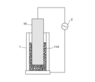
- FIG. 1 and FIG. 2 are schematic diagrams for explaining an example of a method of refining raw material steel by the ESR method to produce high-purity steel.
- FIG. 1 is a diagram schematically showing the state at the start of the production of high-purity steel by the ESR method
- FIG. 2 is the state after a while from the start of FIG. It is a figure which represented typically.
- the raw material steel (electrode 10) is electrically connected to one end of the power supply 2.
- the composition of the raw material steel (electrode 10) is not particularly limited. The composition can be determined to correspond to the high purity steel to be obtained.
- the raw material steel (electrode 10) is installed in the ESR furnace 1 so as to be vertically movable. At the start of manufacturing, a solid (granular at room temperature) flux 11A is spread over the lateral and lower portions of the raw material steel (electrode 10). Flux 11A has the composition described above.
- the other end of a power supply 2 is electrically connected to the conductive hearth of the ESR furnace 1 .
- the furnace wall of the ESR furnace 1 may be provided with cooling means such as water cooling means (not shown in FIG. 1). Although the ESR furnace 1 is shown in an open configuration in FIG. 1, the smelting of the raw steel may be carried out in a closed, atmosphere-controlled ESR furnace.
- a current is supplied from the power source 2 to energize the electrode 10 and the flux 11A. Then, the flux 11A and the tip of the electrode 10 are melted by resistance heat. The flux 11A melts and becomes slag 11. FIG. Also, the metal melted from the tip of the electrode 10 descends through the slag 11 . At this time, impurities (such as sulfur atoms) in the metal are taken into the slag 11, and the raw steel is refined. The fallen metal forms a molten pool 12 below the slag 11 . Then, it is gradually cooled to produce high-purity steel (ingot 13) (see FIG. 2). In FIG.
- the liquid surface of the slag 11 gradually moves upward as the ingot 13 and the molten pool 12 are produced. Therefore, the electrode 10 is appropriately moved in accordance with this, and the remelting of the electrode 10 is continuously performed. As described above, high-purity steel can be obtained.
- Embodiments of the present invention will be described in detail based on examples and comparative examples. In addition, the present invention is not limited to the examples.
- the raw materials were mixed in a gravity mixer according to the raw material ratios in Table 1 to obtain a substantially uniform mixture. After that, the mixture was put into a three-phase arc furnace and heated to 1800° C. or higher under the conditions of a current value of 3.0 to 3.5 kA and a voltage value of 150 to 200 V to obtain a molten mixture. The melting time at this time was 3 hours.
- the resulting molten mixture was pulverized using a cone crusher and screened by passing through a sieve with a nominal opening of 4.75 mm specified in JIS Z 8801-1:2019.
- the molten mixture that did not pass through the sieve was crushed again using a cone crusher and passed through a sieve with a nominal opening of 4.75 mm specified in JIS Z 8801-1: 2019. sorted by These operations were performed until all of the molten mixture passed through the sieve (falls under the sieve). After that, it was screened by passing through a sieve with a nominal opening of 500 ⁇ m specified in JIS Z 8801-1:2019 to obtain particles.
- Examples 1 and 2 The fluxes of Examples 1 and 2 were obtained by mixing the obtained particles 1 to 3 with a gravity mixer. The mixing ratio was 62.2% by mass for particles 1 and 37.8% by mass for particles 2 in Example 1, and 40.2% by mass for particles 1 and 35.4% by mass for particles 2 in Example 2. Particle 3: 24.4% by mass.
- Each of the above fluxes of each particle size is separately placed in a cylindrical aluminum dish (upper diameter: ⁇ 59 mm, lower diameter: ⁇ 45 mm) with an open top, 5 points of each particle size x 10 g (total 15 points), It was aged in an environment of 30° C. and 85% RH. Then, 7 days, 14 days, and 28 days after the start of aging, the aluminum pan containing the flux of each particle size was taken out together with the flux inside. Moisture contents W7 , W14 and W28 after 14 days and 28 days were determined.
Landscapes
- Chemical & Material Sciences (AREA)
- Engineering & Computer Science (AREA)
- Materials Engineering (AREA)
- Metallurgy (AREA)
- Organic Chemistry (AREA)
- Manufacturing & Machinery (AREA)
- Mechanical Engineering (AREA)
- Nonmetallic Welding Materials (AREA)
- Treatment Of Steel In Its Molten State (AREA)
Abstract
Description
ここで、スラグとしては、CaF2、Al2O3およびCaOを主成分とするものがしばしば用いられる。すなわち、CaF2、Al2O3およびCaOを主成分とする固形状のフラックスを、高温で溶融させてスラグとすることがしばしば行われる。
エレクトロスラグ再溶解法に用いられるフラックスであって、
CaF2成分を含む粒子と、Al2O3成分とCaO成分を含む粒子と、の混合物を含み、
カールフィッシャー法により求められる当該フラックスの初期含水率をWとし、当該フラックスを30℃、85%RH環境下に14日間置いたときの含水率W14と初期含水率Wの差で表される含水率変化をΔWとしたとき、Wが0.05質量%以下であり、ΔWが0.03質量%以下であるフラックスが提供される。
上記フラックスの製造方法であって、
少なくとも、CaF2成分を含む化合物を焼成し、CaF2成分を含む粒子を得る焼成工程と、
少なくとも、CaO成分を含む化合物とAl2O3成分を含む化合物とを溶融混合してCaO成分とAl2O3成分を含む溶融混合物を得る溶融混合工程と、
上記CaO成分とAl2O3成分を含む溶融混合物を粉砕することで、CaO成分とAl2O3成分を含む粉砕物を得る粉砕工程と、
上記CaO成分とAl2O3成分を含む粉砕物を、JIS Z 8801-1:2019で規定された公称目開き500μmの篩を通すことでCaO成分とAl2O3成分を含む粒子を得る選別工程と、
少なくとも、上記CaF2成分を含む粒子と上記CaO成分とAl2O3成分を含む粒子とを混合してフラックスを得る混合工程と、
を含む、フラックスの製造方法
が提供される。
原料鋼を、エレクトロスラグ再溶解法による再溶解によって高純度鋼に精錬する工程を含む、高純度鋼の製造方法であって、
溶融スラグとして、上記フラックスの溶融物を用いる、高純度鋼の製造方法
が提供される。
図面において、同様な構成要素には同様の符号を付し、適宜説明を省略する。
煩雑さを避けるため、同一図面内に同一の構成要素が複数ある場合には、その1つのみに符号を付し、全てには符号を付さない場合がある。
図面はあくまで説明用のものである。図面中の各部材の形状や寸法比などは、必ずしも現実の物品と対応するものではない。
本実施形態のフラックスは、エレクトロスラグ再溶解法に用いられるものである。
このフラックスは、CaF2成分を含む粒子と、Al2O3成分とCaO成分を含む粒子と、の混合物を含み、カールフィッシャー法により求められる当該フラックスの初期含水率(保管日数が0日のときの含水率)をWとし、当該フラックスを30℃、85%RH環境下に14日間置いたときの含水率W14と初期含水率Wの差で表される含水率変化(14日後の含水率W14-初期含水率W)をΔWとしたとき、Wが0.05質量%以下であり、ΔWが0.03質量%以下であるフラックスである。このとき、Wは0.05質量%以下、好ましくは0.03質量%以下、より好ましくは0.02質量%以下であり、さらに好ましくは0.015質量%以下である。また、ΔWは0.03質量%以下、好ましくは0.01質量%以下であり、より好ましくは0.007質量%以下であり、さらに好ましくは0.005質量%以下である。
ここで、Wの下限は理想的には0であるが、現実的には例えば0.00001質量%以上である。また、ΔWの下限値は例えば-0.005%以上である。
また、このときの初期含水率Wおよび含水率変化ΔWは、当該フラックスの全粒度における初期含水率Wおよび含水率変化ΔWを指す。
(1)フラックスの原料であるCaF2成分を含む焼成物と、CaO成分とAl2O3成分を含む金属酸化物とを別々に製造した後に配合すること、かつ/または、
(2)CaO成分とAl2O3成分を含む粉砕物を、CaF2成分を含む焼成物と配合する前に篩にかけて吸湿性の高い低粒度の微粉を取り除くことが好ましい。
(1)については以下で、(2)については後述の<フラックスの製造方法>にて説明する。
本実施形態では、30℃、85%RH環境下という一定条件の下、袋に入れない裸の状態のフラックスの吸湿性を評価することで、フラックス自体の吸湿性を適切に測定できるようにしている。そして、本実施形態のフラックスは、その測定により求められるΔWが一定の数値範囲にある。
本実施形態のフラックスは、JIS Z 8801-1:2019で規定された公称目開き500μmの篩に通したとき、篩にかけた当該フラックスの質量に対する、篩下に落下した当該フラックスの質量の比率である通過率が好ましくは18%以下であり、より好ましくは15%以下であり、さらに好ましくは12%以下であり、さらに好ましくは10%以下であり、さらに好ましくは8%以下である。これにより、フラックスの吸湿性をより好適に抑制でき、水素脆化が抑制された高純度金属を歩留まり良く製造することができる。
また、通過率の下限は理想的には0%であるが、現実的には例えば0.00001%以上である。
また、通過率の下限は好ましくは18%以上であり、より好ましくは20%以上であり、さらに好ましくは21%以上である。これにより、当該フラックスを保管する際の「かさ」を減らしたり、精錬の際に当該フラックスを溶融させやすくしたりする。
また、通過率の下限は好ましくは45%以上であり、より好ましくは55%以上であり、さらに好ましくは60%以上であり、さらに好ましくは65%以上であり、さらに好ましくは70%以上であり、さらに好ましくは74%以上であり、さらに好ましくは77%以上である。これにより、当該フラックスを保管する際の「かさ」を減らしたり、精錬の際に当該フラックスを溶融させやすくしたりする。
・CaF2成分およびAl2O3成分
本実施形態のフラックスは、CaF2成分と、Al2O3成分とを含むことが好ましい。
ここでフラックスがさらにCaO成分を含む場合、Al2O3成分はカルシウムアルミネート結晶相(3CaO―Al2O3、12CaO-7Al2O3、CaO-Al2O3、CaO-2Al2O3、CaO-6Al2O3)として存在する。そのため本実施形態において、「Al2O3成分」としては単体のAl2O3成分だけでなく、カルシウムアルミネート結晶相のAl2O3成分も含む。
より好ましくは、CaF2成分の一部または全部はCaF2結晶相として、Al2O3成分の一部または全部はカルシウムアルミネート結晶相として、本実施形態のフラックス中に存在する。
フラックスが、CaF2成分とAl2O3成分とを含むことで、適当なフラックスの融解温度を得ることができる等のメリットがある。また、フラックスがさらにCaO成分を含み、Al2O3成分がカルシウムアルミネート結晶相として存在することにより、フラックスの融解温度をより好適にすることができる。
本実施形態のフラックスがAl2O3成分を含む場合、フラックス中の結晶相全体におけるAl2O3結晶相およびカルシウムアルミネート結晶相の合計の含有率は、好ましくは20質量%以上80質量%以下、より好ましくは35質量%以上65質量%以下である。
さらに、原料混合時におけるフラックス全体中のAl2O3成分の量の上限値は、40質量%以下が好ましく、37質量%以下がより好ましく、35質量%以下がさらに好ましく、32質量%以下がさらに好ましい。また、フラックス全体中のAl2O3成分の量の下限値は、5質量%以上が好ましく、10質量%以上がより好ましく、15質量%以上がさらに好ましく、16質量%以上がさらに好ましい。
本実施形態のフラックスにおいて、原料混合時におけるフラックス全体中のCaO成分の量の上限値は、好ましくは40質量%以下であり、より好ましくは37質量%以下であり、さらに好ましくは35質量%以下であり、さらに好ましくは30質量%以下であり、さらに好ましくは29質量%以下である。
CaO成分は吸湿性が高い物質である。よって、原料混合時におけるフラックス全体中のCaO成分の量を少なくし、フラックス中のCaO結晶相の量を少なくすることで、フラックスの吸湿性をより好適に抑制でき、水素脆化が抑制された高純度金属を歩留まり良く製造することができる。
本実施形態のフラックスは、上記以外の成分として、例えば、MgO成分、SiO2成分などの成分を1つまたは複数含んでもよい。
フラックスが適量のMgO成分を含むことにより、フラックスの融点を低く維持しつつ、フラックスを溶融させて得たスラグの塩基度を適度に高くすることができると考えられる。このことは、インゴット製造の際の硫黄成分の除去性能の点で好ましい。
フラックスが適量のSiO2成分を含むことにより、硫黄成分の除去性等の性能を維持しつつ、フラックスを溶融させて得たスラグの電気抵抗を高める設計を行いやすくなる。これは電極金属を溶解させやすくなる点で好ましい。また、フラックスが適量のSiO2成分を含むことにより、鋼のフェライト相を強化し、精錬後の鋼の強度が高まる傾向にある。
本実施形態のフラックスがさらにSiO2成分を含む場合、その含有率は、フラックス全体中、好ましくは0.3質量%以上3.0質量%以下、より好ましくは0.5質量%以上2.5質量%以下である。
CaF2、Al2O3、CaOおよびAl2O3とCaOとが反応したカルシウムアルミネートのそれぞれの結晶相の含有率は、例えば、粉末X線回折(XRD)パターンをリートベルト法により解析することで定量分析することができる。
より具体的には、XRD分析により得られる回折強度-入射角のチャートと結晶構造モデルからシミュレートするXRDパターンと比較し、実験と計算XRDパターンの残差が最小となるように最小二乗法で質量分率を最適化する方法を通じて、各含有率を求めることができる。
具体的には、不純物の含有率は、フラックス全体中、好ましくは5質量%以下、より好ましくは3質量%以下、さらに好ましくは1質量%以下である。
本実施形態のフラックスの性状は様々でありうる。当該フラックスの含水率変化を所望の値に制御する(そしてそれにより水素脆化が抑制された高純度金属を歩留まり良く製造する)観点からは、常温で粒状であることが好ましい。常温とは、例えば25℃である。
次に、本実施形態に係るフラックスの製造方法について説明する。
本実施形態のフラックスの製造方法は、少なくとも、CaF2を含む化合物を焼成し、CaF2を含む粒子を得る焼成工程と、少なくとも、CaOを含む化合物とAl2O3を含む化合物とを溶融混合してCaOとAl2O3を含む溶融混合物を得る溶融混合工程と、
上記CaOとAl2O3を含む溶融混合物を粉砕することで、CaOとAl2O3を含む粉砕物を得る粉砕工程と、上記CaOとAl2O3を含む粉砕物を、JIS Z 8801-1:2019で規定された公称目開き500μmの篩を通すことでCaOとAl2O3を含む粒子を得る選別工程と、少なくとも、上記CaF2を含む粒子と上記CaOとAl2O3を含む粒子とを混合してフラックスを得る混合工程と、を含む製造方法で得ることができる。
はじめに、原料であるCaF2成分を含む化合物を焼成し、CaF2成分を含む粒子を得る。この工程により、CaF2成分を含む粒子中の水分を蒸発させ、フラックスの吸湿性をより好適に抑制することができる。
この工程における焼成温度および焼成時間としては、CaF2成分を含む化合物中の水分を蒸発させることができる焼成温度と焼成時間であればいずれでもよく、例えば、1200℃で1時間焼成しても良い。
つづいて、前述の焼成工程において得られたCaF2成分を含む粒子とは別に、CaO成分を含む化合物とAl2O3成分を含む化合物とを溶融混合してCaO成分とAl2O3成分を含む溶融混合物を得る。この工程により、フラックス中におけるCaO成分の含有量を制御しつつ、本実施形態のフラックスの融解温度を好適にすることができる。
このとき、CaO成分を含む化合物とAl2O3成分を含む化合物とを溶融混合する溶融温度としては、1800℃以上であることが好ましい。また、CaO成分を含む化合物とAl2O3成分を含む化合物とを溶融混合する溶融時間としては、3時間以上が好ましい。
つづいて、上記(2)で述べたように、前述の溶融混合工程において得られたCaO成分とAl2O3成分を含む溶融混合物を粉砕することで、CaO成分とAl2O3成分を含む粉砕物を得る。この工程により、本実施形態のフラックスにおける含水率変化を制御し、本実施形態のフラックスにおける吸湿性をより好適に抑制することができる。
溶融混合物の粉砕方法としては、本実施形態のフラックスにおける含水率変化を達成できれば、従来公知のいずれの粉砕方法を用いてもよいが、例えば、ボールミル、ビーズミル、振動ミル、ターボミル、メカノフュージョン、ロールクラッシャー、コーンクラッシャー、ジョークラッシャー、ハンマーミル、ディスクミル、ロールミル等の粉砕・分散機;削岩機;振動ドリル;インパクトドライバ;高圧型グライディングロール;ローラ式竪型ミルやボール式竪型ミル等の竪型ミル等が挙げられる。
つづいて、前述の粉砕工程において得られたCaO成分とAl2O3成分を含む粉砕物を、JIS Z 8801-1:2019で規定された公称目開き500μmの篩を通すことで篩上のCaO成分とAl2O3成分を含む粒子を得る。この工程により、粉砕工程において発生した、粒度が小さく吸湿性の高い微粉を取り除き、本実施形態のフラックスにおける吸湿性をより好適に抑制することができる。
最後に、前述の焼成工程において得られたCaF2成分を含む粒子と、前述の選別工程において得られたCaO成分とAl2O3成分を含む粒子とを混合する。
予め粒度が小さく吸湿性の高い微粉を取り除くことにより、本実施形態のフラックスにおける含水率変化を制御でき、結果としてフラックスの吸湿性をより好適に抑制でき、水素脆化が抑制された高純度金属を歩留まり良く製造することができる。
図1および図2は、原料鋼を、ESR法により精錬し、高純度鋼を製造する方法の一例を説明するための模式図である。具体的には、図1は、ESR法による高純度鋼の製造のスタート時の状態を模式的に表した図であり、図2は、図1のスタート時からしばらく時間が経った後の状態を模式的に表した図である。
原料鋼(電極10)は、ESR炉1内に、上下に移動可能に設置されている。製造のスタート時点においては、原料鋼(電極10)の横部および下部に、固形状(常温で粒状)のフラックス11Aが敷き詰められている。フラックス11Aは上述の組成のものである。
ESR炉1の導電性炉床には、電源2の他端が電気的に接続されている。
ESR炉1の炉壁には、水冷手段などの冷却手段が設けられていてもよい(図1には図示せず)。
図1で、ESR炉1は開放された形態で図示されているが、原料鋼の製錬は、密閉型で雰囲気調整を行うESR炉で行われてもよい。
図2においては、インゴット13および溶融プール12の生成に伴って、スラグ11の液面は次第に上方に移動する。よって、それに合わせて電極10を適切に移動させて、電極10の再溶解を連続的に行う。
以上により、高純度鋼を得ることができる。
まず、原料として以下のCaF2成分を含む化合物と、Al2O3成分を含む化合物と、CaO成分を含む化合物を準備した。
・CaF2成分を含む化合物:富士フィルム和光純薬株式会社製、製品名=ふっ化カルシウム、純度98質量%以上
・Al2O3成分を含む化合物:日本軽金属株式会社製、製品名=SMM-23A、純度99質量%以上
・CaO成分を含む化合物:吉澤石灰工業株式会社製、製品名=生石灰、純度99質量%以上
ここで、CaF2成分を含む化合物は少量のMgO成分、SiO2成分などを含んでいた。
これらの原料を表1に示す原料比で混合し、後述の(焼成品の製造方法)もしくは(溶融品の製造方法)に従って処理を行うことによって粒子1(CaF2成分を含む粒子)、粒子2および3(金属酸化物を含む粒子)を得た。

以下に「焼成品」および「溶融品」の製造方法を示す。
上記原料を表1における原料比に従ってロータリーキルンに入れ、1200℃で1時間焼成を行い、粒子を得た。
上記原料を表1における原料比に従って重力式ミキサーで混合し、ほぼ均一な混合物とした。
その後、その混合物を、三相アーク炉に投入し、電流値:3.0から3.5kA、電圧値:150から200Vの条件で1800℃以上に加熱して溶融させ、溶融混合物を得た。このときの溶融時間は3時間とした。
得られた粒子1~3を重力式ミキサーで混合することで実施例1および2のフラックスを得た。混合の割合は、実施例1では粒子1:62.2質量%、粒子2:37.8質量%とし、実施例2では粒子1:40.2質量%、粒子2:35.4質量%、粒子3:24.4質量%とした。
まず、原料の、CaF2成分を含む化合物と、Al2O3成分を含む化合物と、CaO成分を含む化合物とを重力式ミキサーで混合し、ほぼ均一な混合物とした。混合の割合は、CaF2成分を含む化合物:42.3質量%、Al2O3成分を含む化合物:31.4質量%、CaO成分を含む化合物:27.3質量%とした。
次に、この混合物を、JIS Z 8801-1:2019で規定された公称目開き500μmの篩を通さないこと以外は前述の(溶融品の製造方法)と同様の方法によって処理し、得られた粒子を比較例1とした。
得られた各実施例および比較例のフラックスについて、以下の方法で評価を行った。
フラックス全体としての吸湿性に加え、粒度による吸湿性の違いについても調べるため、フラックスを粒度別に分けたうえで、30℃、85%RH環境下に曝露した。具体的には以下(1)~(6)の手順で、フラックスの篩分け、含水率測定などを行った。
(2)フラックスを、JIS Z8801-1:2019で規定された公称目開き2.8mmの篩(ASTM E11のNo.7の篩に相当)に通した。これにより、粒度が4.75~2.8mmのフラックスを選別した。そして、篩を通過できなかった篩残分の質量を測定した。
(3)上記(2)で篩を通過した成分を、JIS Z8801-1:2019で規定された公称目開き1mmの篩(ASTM E11のNo.18の篩に相当)に通した。これにより、粒度が1~2.8mmのフラックスを選別した。そして、篩を通過できなかった篩残分の質量を測定した。
(4)上記(3)で篩を通過した成分を、JIS Z8801-1:2019で規定された公称目開き500μmの篩(ASTM E11のNo.35の篩に相当)に通した。これにより、粒度が0.5~1mmのフラックスと、粒度が0.5mm以下のフラックスを選別した。そして、粒度が0.5~1mmのフラックス(篩残分)の質量と、粒度が0.5mm以下のフラックス(篩を通過した成分)の質量を測定した。
その後、全粒度のフラックスにおいて、14日後の含水率W14と初期含水率Wとの差の値を含水率変化ΔWとして算出した。結果を表2に示す。
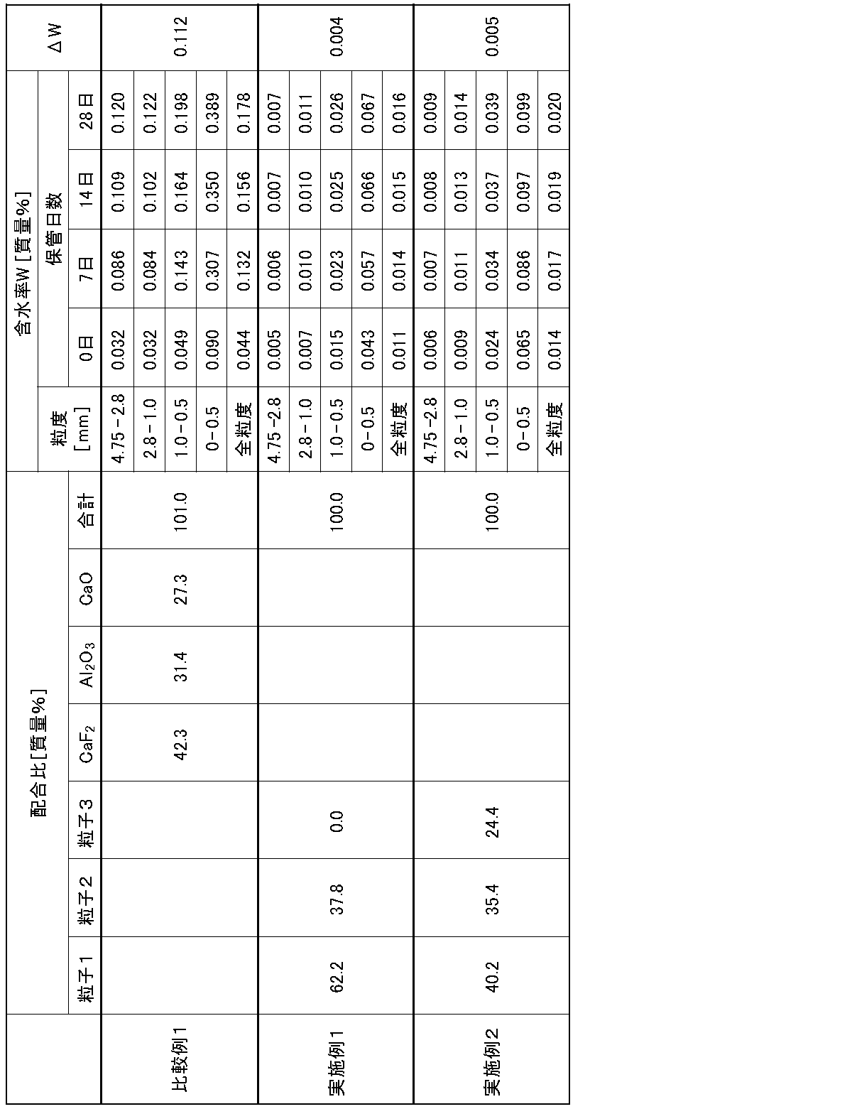
製造後28日以上経過した実施例1~2のフラックスを、事前の乾燥処理を行わずにそのまま用いて、図1、2に示されたようなESR炉により、硫黄などの不純物を含む原料鋼を精錬してインゴットを製造した。水素脆化が十分に抑えられたインゴットを、歩留まりよく製造可能なことを確認した。
一方、実施例1~2のフラックスの代わりに、製造後28日以上経過した比較例1のフラックスを、事前の乾燥処理を行わずにそのまま用いたところ、実施例1~2に比べて水素脆化が抑えられず、インゴットの歩留まりは悪い結果であった。
2 電源
10 電極
11A フラックス
11 スラグ
12 溶融プール
13 インゴット
Claims (5)
- エレクトロスラグ再溶解法に用いられるフラックスであって、
CaF2成分を含む粒子と、Al2O3成分とCaO成分を含む粒子と、の混合物を含み、
カールフィッシャー法により求められる当該フラックスの初期含水率をWとし、当該フラックスを30℃、85%RH環境下に14日間置いたときの含水率W14と初期含水率Wの差で表される含水率変化をΔWとしたとき、Wが0.05質量%以下であり、ΔWが0.03質量%以下であるフラックス。 - 請求項1に記載のフラックスであって、
Wが0.02質量%以下であるフラックス。 - 請求項1または2に記載のフラックスであって、
ΔWが0.01質量%以下であるフラックス。 - 請求項1~3のいずれか1項に記載のフラックスの製造方法であって、
少なくとも、CaF2成分を含む化合物を焼成し、CaF2成分を含む粒子を得る焼成工程と、
少なくとも、CaO成分を含む化合物とAl2O3成分を含む化合物とを溶融混合してCaO成分とAl2O3成分を含む溶融混合物を得る溶融混合工程と、
前記CaO成分とAl2O3成分を含む溶融混合物を粉砕することで、CaO成分とAl2O3成分を含む粉砕物を得る粉砕工程と、
前記CaO成分とAl2O3成分を含む粉砕物を、JIS Z 8801-1:2019で規定された公称目開き500μmの篩を通すことで篩上のCaO成分とAl2O3成分を含む粒子を得る選別工程と、
少なくとも、前記CaF2成分を含む粒子と、前記選別工程で得られた篩上のCaO成分とAl2O3成分を含む粒子とを混合してフラックスを得る混合工程と、
を含む、フラックスの製造方法。 - 原料鋼を、エレクトロスラグ再溶解法による再溶解によって高純度鋼に精錬する工程を含む、高純度鋼の製造方法であって、
溶融スラグとして、請求項1~3のいずれか1項に記載のフラックスの溶融物を用いる、高純度鋼の製造方法。
Priority Applications (2)
| Application Number | Priority Date | Filing Date | Title |
|---|---|---|---|
| EP22892399.1A EP4424856A4 (en) | 2021-11-09 | 2022-09-09 | FLUX USED IN ELECTROCONDUCTIVE SLAG REMELT, PROCESS FOR PRODUCING THIS FLUX, AND PROCESS FOR PRODUCING HIGH-PURE STEEL |
| JP2023559446A JP7734204B2 (ja) | 2021-11-09 | 2022-09-09 | エレクトロスラグ再溶解法に用いられるフラックス、そのフラックスの製造方法および高純度鋼の製造方法 |
Applications Claiming Priority (2)
| Application Number | Priority Date | Filing Date | Title |
|---|---|---|---|
| JP2021182353 | 2021-11-09 | ||
| JP2021-182353 | 2021-11-09 |
Publications (1)
| Publication Number | Publication Date |
|---|---|
| WO2023084898A1 true WO2023084898A1 (ja) | 2023-05-19 |
Family
ID=86335442
Family Applications (1)
| Application Number | Title | Priority Date | Filing Date |
|---|---|---|---|
| PCT/JP2022/033883 Ceased WO2023084898A1 (ja) | 2021-11-09 | 2022-09-09 | エレクトロスラグ再溶解法に用いられるフラックス、そのフラックスの製造方法および高純度鋼の製造方法 |
Country Status (3)
| Country | Link |
|---|---|
| EP (1) | EP4424856A4 (ja) |
| JP (1) | JP7734204B2 (ja) |
| WO (1) | WO2023084898A1 (ja) |
Citations (7)
| Publication number | Priority date | Publication date | Assignee | Title |
|---|---|---|---|---|
| JPS54103718A (en) * | 1978-02-03 | 1979-08-15 | Hitachi Ltd | Synthetic basic slag used for re-melting electroslag |
| JPS5760411B2 (ja) | 1980-09-26 | 1982-12-20 | Wacker Chemie Gmbh | |
| JPH0762461A (ja) * | 1993-06-30 | 1995-03-07 | Daido Steel Co Ltd | 含硫黄鋼材のエレクトロスラグ再溶解法 |
| JP2013049908A (ja) | 2011-08-31 | 2013-03-14 | Jfe Steel Corp | エレクトロスラグ再溶解法による高純度鋼の溶製方法 |
| WO2020195838A1 (ja) * | 2019-03-26 | 2020-10-01 | デンカ株式会社 | エレクトロスラグ再溶解法に用いられるフラックス、そのフラックスの溶融物を用いる高純度鋼の製造方法、および、そのフラックスの製造方法 |
| WO2020195840A1 (ja) * | 2019-03-26 | 2020-10-01 | デンカ株式会社 | エレクトロスラグ再溶解法に用いられるフラックス、そのフラックスの製造方法および高純度鋼の製造方法 |
| JP2021182353A (ja) | 2020-05-14 | 2021-11-25 | 株式会社すなおネット | 情報配信システム |
Family Cites Families (3)
| Publication number | Priority date | Publication date | Assignee | Title |
|---|---|---|---|---|
| RU2115529C1 (ru) * | 1996-09-19 | 1998-07-20 | Центральный научно-исследовательский институт конструкционных материалов "Прометей" | Плавленный флюс для наплавки |
| CN105603204B (zh) * | 2016-03-21 | 2018-04-06 | 河南省西保冶材集团有限公司 | 奥氏体气阀钢重熔保护渣及其制备方法 |
| JP6917170B2 (ja) * | 2017-03-31 | 2021-08-11 | 株式会社神戸製鋼所 | サブマージアーク溶接用フラックスおよびその製造方法 |
-
2022
- 2022-09-09 EP EP22892399.1A patent/EP4424856A4/en not_active Withdrawn
- 2022-09-09 JP JP2023559446A patent/JP7734204B2/ja active Active
- 2022-09-09 WO PCT/JP2022/033883 patent/WO2023084898A1/ja not_active Ceased
Patent Citations (7)
| Publication number | Priority date | Publication date | Assignee | Title |
|---|---|---|---|---|
| JPS54103718A (en) * | 1978-02-03 | 1979-08-15 | Hitachi Ltd | Synthetic basic slag used for re-melting electroslag |
| JPS5760411B2 (ja) | 1980-09-26 | 1982-12-20 | Wacker Chemie Gmbh | |
| JPH0762461A (ja) * | 1993-06-30 | 1995-03-07 | Daido Steel Co Ltd | 含硫黄鋼材のエレクトロスラグ再溶解法 |
| JP2013049908A (ja) | 2011-08-31 | 2013-03-14 | Jfe Steel Corp | エレクトロスラグ再溶解法による高純度鋼の溶製方法 |
| WO2020195838A1 (ja) * | 2019-03-26 | 2020-10-01 | デンカ株式会社 | エレクトロスラグ再溶解法に用いられるフラックス、そのフラックスの溶融物を用いる高純度鋼の製造方法、および、そのフラックスの製造方法 |
| WO2020195840A1 (ja) * | 2019-03-26 | 2020-10-01 | デンカ株式会社 | エレクトロスラグ再溶解法に用いられるフラックス、そのフラックスの製造方法および高純度鋼の製造方法 |
| JP2021182353A (ja) | 2020-05-14 | 2021-11-25 | 株式会社すなおネット | 情報配信システム |
Non-Patent Citations (1)
| Title |
|---|
| See also references of EP4424856A4 |
Also Published As
| Publication number | Publication date |
|---|---|
| JPWO2023084898A1 (ja) | 2023-05-19 |
| EP4424856A4 (en) | 2025-07-02 |
| JP7734204B2 (ja) | 2025-09-04 |
| EP4424856A1 (en) | 2024-09-04 |
Similar Documents
| Publication | Publication Date | Title |
|---|---|---|
| Jayasankar et al. | Production of pig iron from red mud waste fines using thermal plasma technology | |
| JP4382812B2 (ja) | 高純度一酸化ニオブ(NbO)の製造及びそれから作ったコンデンサ製品 | |
| Abdel-latif | Recovery of vanadium and nickel from petroleum flyash | |
| WO2020195840A1 (ja) | エレクトロスラグ再溶解法に用いられるフラックス、そのフラックスの製造方法および高純度鋼の製造方法 | |
| TWI840473B (zh) | 製造用於鋼脫硫之爐渣調整劑的方法、爐渣調整劑及其用途 | |
| EP3950173B1 (en) | Flux configured to be used in electroslag remelting method, and flux production method | |
| WO2018182025A1 (ja) | サブマージアーク溶接用フラックス | |
| JP7734204B2 (ja) | エレクトロスラグ再溶解法に用いられるフラックス、そのフラックスの製造方法および高純度鋼の製造方法 | |
| JP7734203B2 (ja) | エレクトロスラグ再溶解法に用いられるフラックス、そのフラックスの製造方法および高純度鋼の製造方法 | |
| KR102938340B1 (ko) | 유가 금속을 회수하는 방법 | |
| Park et al. | Novel design of ferronickel smelting slag by utilizing red mud as a fluxing agent: Thermochemical computations and experimental confirmation | |
| WO2011027334A1 (en) | Processing of metallurgical slag | |
| KR100732539B1 (ko) | 알루미늄 및 형석을 함유하는 제강용 플럭스 조성물 | |
| KR100759862B1 (ko) | 저온형 제강정련용 플럭스 조성물 | |
| Fernández-Caliani et al. | Mineral chemistry and phase equilibrium constraints on the origin of accretions formed during copper flash smelting | |
| Mehrabi et al. | The effect of slag types and melting rate on electro-slag remelting (ESR) processing | |
| RU2701594C1 (ru) | Обработка богатых железом редкоземельных руд | |
| KR20250049394A (ko) | 유가 금속의 제조 방법 | |
| Botha et al. | Effect of silica concentration on degree of sintering of chromite-silica ladle well filler sand based on South African raw materials | |
| Morscheiser et al. | Sulphur control in nickel-based superalloy production | |
| KR100732540B1 (ko) | 알루미늄 및 형석을 함유하는 제강용 플럭스의 제조방법 | |
| JP6026210B2 (ja) | 金属の還元精錬方法 | |
| Tangstad et al. | Reduction of agglomerated manganese ores in a 150 kW pilot scale furnace | |
| Morscheiser et al. | The influence of the slag composition on the desulfurization of Ni-based superalloys | |
| CN112400028A (zh) | 钙、铝及硅合金以及其生产方法 |
Legal Events
| Date | Code | Title | Description |
|---|---|---|---|
| 121 | Ep: the epo has been informed by wipo that ep was designated in this application |
Ref document number: 22892399 Country of ref document: EP Kind code of ref document: A1 |
|
| ENP | Entry into the national phase |
Ref document number: 2023559446 Country of ref document: JP Kind code of ref document: A |
|
| WWE | Wipo information: entry into national phase |
Ref document number: 2022892399 Country of ref document: EP |
|
| ENP | Entry into the national phase |
Ref document number: 2022892399 Country of ref document: EP Effective date: 20240531 |
|
| WWW | Wipo information: withdrawn in national office |
Ref document number: 2022892399 Country of ref document: EP |