WO2023084931A1 - 発電システム - Google Patents
発電システム Download PDFInfo
- Publication number
- WO2023084931A1 WO2023084931A1 PCT/JP2022/035429 JP2022035429W WO2023084931A1 WO 2023084931 A1 WO2023084931 A1 WO 2023084931A1 JP 2022035429 W JP2022035429 W JP 2022035429W WO 2023084931 A1 WO2023084931 A1 WO 2023084931A1
- Authority
- WO
- WIPO (PCT)
- Prior art keywords
- diameter wheel
- arm
- cam
- wheel arm
- small
- Prior art date
- Legal status (The legal status is an assumption and is not a legal conclusion. Google has not performed a legal analysis and makes no representation as to the accuracy of the status listed.)
- Ceased
Links
Images






Classifications
-
- H—ELECTRICITY
- H02—GENERATION; CONVERSION OR DISTRIBUTION OF ELECTRIC POWER
- H02K—DYNAMO-ELECTRIC MACHINES
- H02K7/00—Arrangements for handling mechanical energy structurally associated with dynamo-electric machines, e.g. structural association with mechanical driving motors or auxiliary dynamo-electric machines
- H02K7/18—Structural association of electric generators with mechanical driving motors, e.g. with turbines
- H02K7/1807—Rotary generators
-
- F—MECHANICAL ENGINEERING; LIGHTING; HEATING; WEAPONS; BLASTING
- F03—MACHINES OR ENGINES FOR LIQUIDS; WIND, SPRING, OR WEIGHT MOTORS; PRODUCING MECHANICAL POWER OR A REACTIVE PROPULSIVE THRUST, NOT OTHERWISE PROVIDED FOR
- F03B—MACHINES OR ENGINES FOR LIQUIDS
- F03B11/00—Parts or details not provided for in, or of interest apart from, the preceding groups, e.g. wear-protection couplings, between turbine and generator
-
- F—MECHANICAL ENGINEERING; LIGHTING; HEATING; WEAPONS; BLASTING
- F03—MACHINES OR ENGINES FOR LIQUIDS; WIND, SPRING, OR WEIGHT MOTORS; PRODUCING MECHANICAL POWER OR A REACTIVE PROPULSIVE THRUST, NOT OTHERWISE PROVIDED FOR
- F03B—MACHINES OR ENGINES FOR LIQUIDS
- F03B17/00—Other machines or engines
- F03B17/06—Other machines or engines using liquid flow with predominantly kinetic energy conversion, e.g. of swinging-flap type, "run-of-river", "ultra-low head"
-
- F—MECHANICAL ENGINEERING; LIGHTING; HEATING; WEAPONS; BLASTING
- F03—MACHINES OR ENGINES FOR LIQUIDS; WIND, SPRING, OR WEIGHT MOTORS; PRODUCING MECHANICAL POWER OR A REACTIVE PROPULSIVE THRUST, NOT OTHERWISE PROVIDED FOR
- F03C—POSITIVE-DISPLACEMENT ENGINES DRIVEN BY LIQUIDS
- F03C2/00—Rotary-piston engines
- F03C2/08—Rotary-piston engines of intermeshing-engagement type, i.e. with engagement of co- operating members similar to that of toothed gearing
-
- F—MECHANICAL ENGINEERING; LIGHTING; HEATING; WEAPONS; BLASTING
- F03—MACHINES OR ENGINES FOR LIQUIDS; WIND, SPRING, OR WEIGHT MOTORS; PRODUCING MECHANICAL POWER OR A REACTIVE PROPULSIVE THRUST, NOT OTHERWISE PROVIDED FOR
- F03D—WIND MOTORS
- F03D15/00—Transmission of mechanical power
- F03D15/10—Transmission of mechanical power using gearing not limited to rotary motion, e.g. with oscillating or reciprocating members
-
- F—MECHANICAL ENGINEERING; LIGHTING; HEATING; WEAPONS; BLASTING
- F03—MACHINES OR ENGINES FOR LIQUIDS; WIND, SPRING, OR WEIGHT MOTORS; PRODUCING MECHANICAL POWER OR A REACTIVE PROPULSIVE THRUST, NOT OTHERWISE PROVIDED FOR
- F03D—WIND MOTORS
- F03D17/00—Monitoring or testing of wind motors, e.g. diagnostics
- F03D17/009—Monitoring or testing of wind motors, e.g. diagnostics characterised by the purpose
- F03D17/022—Monitoring or testing of wind motors, e.g. diagnostics characterised by the purpose for monitoring displacement
-
- F—MECHANICAL ENGINEERING; LIGHTING; HEATING; WEAPONS; BLASTING
- F03—MACHINES OR ENGINES FOR LIQUIDS; WIND, SPRING, OR WEIGHT MOTORS; PRODUCING MECHANICAL POWER OR A REACTIVE PROPULSIVE THRUST, NOT OTHERWISE PROVIDED FOR
- F03D—WIND MOTORS
- F03D7/00—Controlling wind motors
- F03D7/02—Controlling wind motors the wind motors having rotation axis substantially parallel to the air flow entering the rotor
- F03D7/04—Automatic control; Regulation
- F03D7/042—Automatic control; Regulation by means of an electrical or electronic controller
-
- F—MECHANICAL ENGINEERING; LIGHTING; HEATING; WEAPONS; BLASTING
- F03—MACHINES OR ENGINES FOR LIQUIDS; WIND, SPRING, OR WEIGHT MOTORS; PRODUCING MECHANICAL POWER OR A REACTIVE PROPULSIVE THRUST, NOT OTHERWISE PROVIDED FOR
- F03D—WIND MOTORS
- F03D9/00—Adaptations of wind motors for special use; Combinations of wind motors with apparatus driven thereby; Wind motors specially adapted for installation in particular locations
- F03D9/20—Wind motors characterised by the driven apparatus
- F03D9/25—Wind motors characterised by the driven apparatus the apparatus being an electrical generator
-
- F—MECHANICAL ENGINEERING; LIGHTING; HEATING; WEAPONS; BLASTING
- F16—ENGINEERING ELEMENTS AND UNITS; GENERAL MEASURES FOR PRODUCING AND MAINTAINING EFFECTIVE FUNCTIONING OF MACHINES OR INSTALLATIONS; THERMAL INSULATION IN GENERAL
- F16H—GEARING
- F16H25/00—Gearings comprising primarily only cams, cam-followers and screw-and-nut mechanisms
- F16H25/04—Gearings comprising primarily only cams, cam-followers and screw-and-nut mechanisms for conveying rotary motion
-
- F—MECHANICAL ENGINEERING; LIGHTING; HEATING; WEAPONS; BLASTING
- F05—INDEXING SCHEMES RELATING TO ENGINES OR PUMPS IN VARIOUS SUBCLASSES OF CLASSES F01-F04
- F05B—INDEXING SCHEME RELATING TO WIND, SPRING, WEIGHT, INERTIA OR LIKE MOTORS, TO MACHINES OR ENGINES FOR LIQUIDS COVERED BY SUBCLASSES F03B, F03D AND F03G
- F05B2210/00—Working fluid
- F05B2210/16—Air or water being indistinctly used as working fluid, i.e. the machine can work equally with air or water without any modification
-
- F—MECHANICAL ENGINEERING; LIGHTING; HEATING; WEAPONS; BLASTING
- F05—INDEXING SCHEMES RELATING TO ENGINES OR PUMPS IN VARIOUS SUBCLASSES OF CLASSES F01-F04
- F05B—INDEXING SCHEME RELATING TO WIND, SPRING, WEIGHT, INERTIA OR LIKE MOTORS, TO MACHINES OR ENGINES FOR LIQUIDS COVERED BY SUBCLASSES F03B, F03D AND F03G
- F05B2220/00—Application
- F05B2220/70—Application in combination with
- F05B2220/706—Application in combination with an electrical generator
-
- F—MECHANICAL ENGINEERING; LIGHTING; HEATING; WEAPONS; BLASTING
- F05—INDEXING SCHEMES RELATING TO ENGINES OR PUMPS IN VARIOUS SUBCLASSES OF CLASSES F01-F04
- F05B—INDEXING SCHEME RELATING TO WIND, SPRING, WEIGHT, INERTIA OR LIKE MOTORS, TO MACHINES OR ENGINES FOR LIQUIDS COVERED BY SUBCLASSES F03B, F03D AND F03G
- F05B2260/00—Function
- F05B2260/40—Transmission of power
-
- F—MECHANICAL ENGINEERING; LIGHTING; HEATING; WEAPONS; BLASTING
- F05—INDEXING SCHEMES RELATING TO ENGINES OR PUMPS IN VARIOUS SUBCLASSES OF CLASSES F01-F04
- F05B—INDEXING SCHEME RELATING TO WIND, SPRING, WEIGHT, INERTIA OR LIKE MOTORS, TO MACHINES OR ENGINES FOR LIQUIDS COVERED BY SUBCLASSES F03B, F03D AND F03G
- F05B2260/00—Function
- F05B2260/40—Transmission of power
- F05B2260/403—Transmission of power through the shape of the drive components
-
- F—MECHANICAL ENGINEERING; LIGHTING; HEATING; WEAPONS; BLASTING
- F05—INDEXING SCHEMES RELATING TO ENGINES OR PUMPS IN VARIOUS SUBCLASSES OF CLASSES F01-F04
- F05B—INDEXING SCHEME RELATING TO WIND, SPRING, WEIGHT, INERTIA OR LIKE MOTORS, TO MACHINES OR ENGINES FOR LIQUIDS COVERED BY SUBCLASSES F03B, F03D AND F03G
- F05B2260/00—Function
- F05B2260/50—Kinematic linkage, i.e. transmission of position
- F05B2260/506—Kinematic linkage, i.e. transmission of position using cams or eccentrics
-
- F—MECHANICAL ENGINEERING; LIGHTING; HEATING; WEAPONS; BLASTING
- F05—INDEXING SCHEMES RELATING TO ENGINES OR PUMPS IN VARIOUS SUBCLASSES OF CLASSES F01-F04
- F05B—INDEXING SCHEME RELATING TO WIND, SPRING, WEIGHT, INERTIA OR LIKE MOTORS, TO MACHINES OR ENGINES FOR LIQUIDS COVERED BY SUBCLASSES F03B, F03D AND F03G
- F05B2270/00—Control
- F05B2270/80—Devices generating input signals, e.g. transducers, sensors, cameras or strain gauges
- F05B2270/821—Displacement measuring means, e.g. inductive
-
- Y—GENERAL TAGGING OF NEW TECHNOLOGICAL DEVELOPMENTS; GENERAL TAGGING OF CROSS-SECTIONAL TECHNOLOGIES SPANNING OVER SEVERAL SECTIONS OF THE IPC; TECHNICAL SUBJECTS COVERED BY FORMER USPC CROSS-REFERENCE ART COLLECTIONS [XRACs] AND DIGESTS
- Y02—TECHNOLOGIES OR APPLICATIONS FOR MITIGATION OR ADAPTATION AGAINST CLIMATE CHANGE
- Y02E—REDUCTION OF GREENHOUSE GAS [GHG] EMISSIONS, RELATED TO ENERGY GENERATION, TRANSMISSION OR DISTRIBUTION
- Y02E10/00—Energy generation through renewable energy sources
- Y02E10/20—Hydro energy
-
- Y—GENERAL TAGGING OF NEW TECHNOLOGICAL DEVELOPMENTS; GENERAL TAGGING OF CROSS-SECTIONAL TECHNOLOGIES SPANNING OVER SEVERAL SECTIONS OF THE IPC; TECHNICAL SUBJECTS COVERED BY FORMER USPC CROSS-REFERENCE ART COLLECTIONS [XRACs] AND DIGESTS
- Y02—TECHNOLOGIES OR APPLICATIONS FOR MITIGATION OR ADAPTATION AGAINST CLIMATE CHANGE
- Y02E—REDUCTION OF GREENHOUSE GAS [GHG] EMISSIONS, RELATED TO ENERGY GENERATION, TRANSMISSION OR DISTRIBUTION
- Y02E10/00—Energy generation through renewable energy sources
- Y02E10/70—Wind energy
Definitions
- the present invention relates to a power generation system capable of generating power using natural energy such as hydraulic power and wind power.
- Patent Document 1 a power generation system disclosed in Patent Document 1 that can generate power using natural energy such as water power and wind power by being installed in rivers, waterways, coasts, places with strong winds, and the like.
- this power generation system when the cam wheel rotates due to hydraulic power or wind power, the cam of the cam wheel comes into contact with the arm mechanism, and the arm mechanism rotates. During rotation of the arm mechanism, the arm mechanism comes into contact with the drive wheel of the rotating body, thereby rotating the rotating body and converting the rotational energy of the rotating body into electric energy to generate power.
- the present invention has been made in view of the above problems, and an object of the present invention is to rotate a cam member by water power or wind power, so that the cam of the cam member comes into contact with an arm mechanism and the arm mechanism rotates.
- an object of the present invention is to rotate a cam member by water power or wind power, so that the cam of the cam member comes into contact with an arm mechanism and the arm mechanism rotates.
- the arm mechanism contacts the wheel of the rotating body while the arm mechanism is rotating, the rotating body rotates, and the rotational energy of the rotating body is converted into electrical energy to generate power.
- a large torque is applied to the rotating body until the rotational speed of the rotating body rises to the first value, and after the rotational speed of the rotating body rises to the first value, the rotation of the rotating body.
- the present invention includes the subjects described in the following sections.
- Section 1 a cam device comprising a cam member having a cam projecting from an outer peripheral surface, wherein the cam member is rotated by hydraulic power or wind power; an arm mechanism that rotates when the cam comes into contact with the cam member during rotation; When the arm mechanism contacts the outer peripheral surface of either the small-diameter wheel or the large-diameter wheel during rotation of the arm mechanism, the rotating body is rotated, and the rotational energy of the rotating body is converted into electrical energy.
- a generator that generates electricity by converting While operating in the first mode in which the arm mechanism is brought into contact with the large-diameter wheel, the arm mechanism is brought into contact with the small-diameter wheel in response to the rotational speed of the rotating body increasing to a first value.
- the first mode in response to transitioning to a second mode of operation and, during operation in the second mode, the rotational speed of the rotor being reduced to a second value that is less than or equal to the first value; and an operation control means for shifting to the operation of the power generation system.
- the arm mechanism includes a cam arm, a large-diameter wheel arm, a small-diameter wheel arm, a main shaft, and biasing means
- the main shaft passes through the base end of the cam arm, the base end of the small-diameter wheel arm, and the base end of the large-diameter wheel arm, Each time the cam comes into contact with the tip of the cam arm due to rotation of the cam member, the cam arm is pressed by the cam to rotate in the first direction about the main shaft,
- the biasing means biases the cam arm in a second direction opposite to the first direction each time the cam arm rotates in the first direction, and the biasing means By the biasing force, the cam arm rotates in the first direction, then reverses and rotates in the second direction
- the operation control means is As the operation in the first mode, Of the large-diameter wheel arm and the small-diameter wheel arm, only the large-diameter wheel arm rotates together with the cam arm in the first direction, then reverses and rotate
- the large-diameter wheel arm is contracted to move the large-diameter wheel arm to the large-diameter wheel arm. While the large-diameter wheel arm rotates in the second direction without contacting the wheel, the large-diameter wheel arm is in an extended state so that the large-diameter wheel arm is in contact with the large-diameter wheel. come into contact with As the operation of the second mode, Of the large-diameter wheel arm and the small-diameter wheel arm, only the small-diameter wheel arm rotates together with the cam arm in the first direction, then reverses and rotates in the second direction.
- the cam arm includes a main shaft penetrating member and a cam arm main body, and the main shaft penetrating member constitutes a base end portion of the cam arm,
- the main shaft penetrating member includes an upper plate, a lower plate arranged below the upper plate with a gap therebetween, and a connecting plate extending in the vertical direction and connecting an intermediate portion of the upper plate and an intermediate portion of the lower plate.
- the cam arm body extends from the connecting plate toward the cam device, A base end portion of the small-diameter wheel arm and a base end portion of the large-diameter wheel arm are disposed in a space closer to the generator than the connecting plate between the upper plate and the lower plate,
- the biasing means includes a base plate, a coil spring arranged on the base plate, an annular plate supported by the upper end of the coil spring, and a roller rotatably attached to the upper surface of the annular plate.
- the main shaft extends upward from the base plate, passes through the inner side of the coil spring and the inner side of the annular plate in order, and is then fixed to the lower plate, the base end of the large-diameter wheel arm, and the main shaft.
- a convex portion having a tapered surface is formed on the lower surface of the lower plate, and the tapered surface is inclined in the second direction toward the lower side, While the cam arm rotates in the first direction, the tapered surface presses the roller due to the rotation of the convex portion in the first direction, so that the tapered surface moves downward from the upper side of the tapered surface.
- a downward force is applied from the annular plate to the coil spring, and the coil spring is put in a compressed state.
- the motion control means includes a first stepping motor having a first motor shaft, a first cam, a second cam, a first stopper, a second stopper, a first stopper spring, a second stopper spring, comprising a rotation sensor and a control device,
- the first cam and the second cam are attached to the first motor shaft with a gap therebetween, and the first stepping motor has the first motor shaft between the upper plate and the lower plate.
- the first cam faces the base end portion of the large-diameter wheel arm
- the second cam faces the base end of the small-diameter wheel arm.
- the first stopper is passed through the first through hole of the connecting plate so as to be movable between the base end of the large-diameter wheel arm and the first cam
- the first stopper spring is a coil spring through which the first stopper passes inside, and is sandwiched between the connecting plate and the first flange protruding from the outer periphery of the first stopper
- the second stopper is passed through the second through hole of the connecting plate so as to be movable between the base end portion of the small-diameter wheel arm and the second cam
- the second stopper spring is a coil spring through which the second stopper passes inside, and is sandwiched between the connecting plate and the second flange protruding from the outer periphery of the second stopper
- a base end portion of the large-diameter wheel arm is formed with a first concave portion for fitting one end portion of the first stopper, A second concave portion for fitting one end portion of the second stopper is formed in
- the rotation sensor is capable of detecting a rotation speed of the rotating body, When a predetermined operation is performed on the input section of the control device, the control device rotates the first motor shaft of the first stepping motor forward, thereby moving one end of the second stopper to the first stepping motor.
- the large-diameter wheel arm rotates together with the cam arm in the first direction, then reverses and rotates in the second direction,
- the control device reversely rotates the first motor shaft of the first stepping motor
- One end of the second stopper is fitted into the second concave portion, and the small-diameter wheel arm rotates in the first direction together with the cam arm, and then reverses to move the cam arm.
- the control device rotates the first motor shaft of the first stepping motor forward, One end of the second stopper is removed from the second recess, and the large-diameter wheel arm rotates in the first direction together with the cam arm, and then reverses to rotate in the second direction.
- Item 4 The power generation system according to Item 3, which rotates in the direction of
- the large-diameter wheel arm includes a first support member and a first moving body,
- the base end portion of the first support member constitutes the base end portion of the large-diameter wheel arm
- the first moving body includes a first joint body, a second joint body, a first rod, and a first elastic member, and includes a distal end portion of the first joint body and a proximal end portion of the second joint body.
- the member extends from the tip of the first rod and constitutes the tip of the large-diameter wheel arm
- the small-diameter wheel arm includes a second support member and a second moving body,
- the base end portion of the second support member constitutes the base end portion of the small-diameter wheel arm
- the second moving body includes a third joint body, a fourth joint body, a second rod, and a second elastic member.
- the motion control means further comprises a second stepping motor having a second motor shaft, a third stepping motor having a third motor shaft, and a position sensor,
- the second stepping motor is supported by the first support member, the second motor shaft is connected to the base end of the first joint body,
- the third stepping motor is supported by the second support member, the third motor shaft is connected to the base end of the third joint,
- the position sensor is capable of detecting that the cam arm has reached a rotation start position in the first direction or a rotation start position in the second direction, While the large-diameter wheel arm rotates in the second direction, the operation control means extends the large-diameter wheel arm so that the cam arm rotates in the second direction.
- the control device rotates the second motor shaft of the second stepping motor forward, thereby moving the first joint body and the second The joint body becomes linear, and the pressure of the second joint body moves the first rod and the first elastic member toward the generator, and the large-diameter wheel arm moves toward the second While rotating in the direction, the first elastic member contacts the large diameter wheel, While the large-diameter wheel arm rotates in the first direction, the operation control means contracts the large-diameter wheel arm so that the cam arm rotates in the first direction.
- the control device When the position sensor detects that the start position has been reached, the control device reversely rotates the second motor shaft of the second stepping motor, thereby moving the first joint body and the second The joint body is bent, and the first rod and the first elastic member are moved toward the cam member by the traction of the second joint body. While rotating in the direction, the first elastic member does not contact the large diameter wheel, While the small-diameter wheel arm rotates in the second direction, the operation control means extends the small-diameter wheel arm so that the cam arm is at the rotation start position in the second direction.
- the position sensor detects that the third joint body and the fourth joint body have reached the becomes a straight line, and the second rod and the second elastic member are moved toward the generator by the pressure of the fourth joint, and the small-diameter wheel arm is rotated in the second direction.
- the second elastic member contacts the small diameter wheel, While the small-diameter wheel arm rotates in the first direction, the movement control means retracts the small-diameter wheel arm so that the cam arm is positioned at the rotation start position in the first direction.
- the controller When the position sensor detects that the third joint body and the fourth joint body are reached, the controller reversely rotates the third motor shaft of the third stepping motor is bent, and the second rod and the second elastic member are moved toward the cam member by the traction of the fourth joint, and the small-diameter wheel arm is rotated in the first direction.
- Item 5 The power generation system according to Item 3 or 4, wherein the second elastic member does not contact the small-diameter wheel during movement.
- the large-diameter wheel arm includes a first support member and a first moving body,
- the base end portion of the first support member constitutes the base end portion of the large-diameter wheel arm
- the first moving body includes a first joint body, a second joint body, a first absorber, a first rod, and a first elastic member, and the first rod moves to the first support member.
- the first absorber includes a first cylinder having an opening at its tip, and a first spring arranged inside the first cylinder.
- the base end is hinged, the tip of the second joint is hinged to the base end of the first cylinder, and the base end of the first spring and the base end of the first cylinder are hinged.
- the small-diameter wheel arm includes a second support member and a second moving body, The base end portion of the second support member constitutes the base end portion of the small-diameter wheel arm,
- the second moving body includes a third joint body, a fourth joint body, a second absorber, a second rod, and a second elastic member, and the second rod moves to the second support member.
- the second absorber includes a second cylinder having an opening at its tip, and a second spring arranged inside the second cylinder.
- the motion control means further comprises a second stepping motor having a second motor shaft, a third stepping motor having a third motor shaft, and a position sensor,
- the second stepping motor is supported by the first support member, the second motor shaft is connected to the base end of the first joint body,
- the third stepping motor is supported by the second support member, the third motor shaft is connected to the base end of the third joint,
- the position sensor is capable of detecting that the cam arm has reached a rotation start position in the first direction or a rotation start position in the second direction, While the large-diameter wheel arm rotates in the second direction, the operation control means extends the large-diameter wheel arm so that the cam arm rotates in the second direction.
- the control device rotates the second motor shaft of the second stepping motor forward, thereby moving the first joint body and the second The joint body becomes linear, and the first cylinder, the first spring, the first rod, and the first elastic member are moved to the generator side, and the large-diameter wheel arm While rotating in the second direction, the first elastic member contacts the large diameter wheel, While the large-diameter wheel arm rotates in the first direction, the operation control means contracts the large-diameter wheel arm so that the cam arm rotates in the first direction.
- the control device When the position sensor detects that the start position has been reached, the control device reversely rotates the second motor shaft of the second stepping motor, thereby moving the first joint body and the second The joint body becomes bent, and the first cylinder, the first spring, the first rod, and the first elastic member move toward the cam wheel, and the large diameter wheel While the arm rotates in the first direction, the first elastic member does not contact the large diameter wheel, While the small-diameter wheel arm rotates in the second direction, the operation control means extends the small-diameter wheel arm so that the cam arm moves to the rotation start position in the second direction.
- the control device causes the third stepping motor to rotate.
- the operation shifts to the second mode in which the small-diameter wheel is brought into contact with the arm mechanism, and operates in the second mode.
- the operation is shifted to the first mode.
- FIG. 4 is a schematic plan view which shows operation
- (A), (B), and (C) are side views showing a large-diameter wheel arm of a modification.
- (A), (B), and (C) are side views showing a small-diameter wheel arm of a modified example.
- (A) and (B) are side views showing an urging means of a modification.
- (A) and (B) are side views showing an urging means of a modification.
- FIG. 1 is a perspective view showing a power generation system 1 according to an embodiment of the invention.
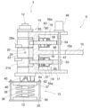
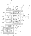
- FIG. 2 is a side view showing the arm mechanism 3 included in the power generation system 1 according to the embodiment of the invention.
- 3 and 4 are side views showing part of the arm mechanism 3 (the hatched areas in FIGS. 3 and 4 are sectional views).
- 5A and 5B are side views showing the large-diameter wheel arm 10 included in the power generation system 1.
- FIG. 6A and 6B are side views showing the small-diameter wheel arm 11 included in the power generation system 1.
- FIG. 7(A) and 7(B) are side views showing the biasing means 13 included in the power generation system 1.
- the power generation system 1 can generate power by being installed in rivers, waterways, coasts, places with strong winds, and the like.
- the power generation system 1 includes a cam device 2, an arm mechanism 3, a power generator 4, and operation control means.
- the cam device 2 has a cam member 7 with a cam 6 protruding from the outer peripheral surface, and the cam member 7 is rotated by water power or wind power.
- the cam member 7 is composed of a cam wheel with the cam 6 protruding from the outer peripheral surface, but the present invention does not limit the cam member 7 to be composed of a cam wheel. 7 may be, for example, a member from which the cam 6 protrudes from the outer peripheral surface of an elongated cylindrical body. In the illustrated example, four cams 6 are formed on the outer peripheral surface of the cam member 7, but the number of cams 6 formed on the outer peripheral surface of the cam member 7 can be one or any number.
- Means for rotating the cam member 7 by hydraulic power or wind power are not particularly limited, but for example, the turbine, transmission, belt mechanism, and coupling disclosed in Patent Document 1 (Japanese Patent Application Laid-Open No. 2018-168799) can be used.
- the cam device 2 is provided with a cam member 7, a main drive shaft 8, and a clutch mechanism (not shown).
- a turbine consists of multiple blades attached in the circumferential direction of a rotating shaft.
- the rotating shaft rotates around the axis by applying hydraulic power or wind power to these blades.
- a transmission consists of an input shaft that rotates when the torque of the rotary shaft is transmitted, an output shaft that rotates when the torque of the input shaft is transmitted, and an input rotation speed, which is the number of rotations per unit time of the input shaft.
- An input rotation speed sensor that measures the output rotation speed sensor that measures the output rotation speed that is the rotation speed per unit time of the output shaft, and the input rotation speed and the output so that the output rotation speed is constant and a control means for controlling a gear ratio, which is a ratio to the number of revolutions.
- the belt mechanism connects the rotating shaft of the turbine and the input shaft of the transmission.
- the coupling connects the output shaft of the transmission and the main drive shaft 8 of the cam device 2 . Torque of the output shaft of the transmission is transmitted to the main drive shaft 8 via this coupling, thereby rotating the main drive shaft 8 .
- the output shaft of the transmission and the main drive shaft 8 may be connected by a known means other than a coupling to transmit the torque of the output shaft of the transmission to the main drive shaft 8 (for example, the transmission If a belt is provided around the output shaft of the transmission and the main drive shaft 8, the torque of the output shaft of the transmission can be transmitted to the main drive shaft 8 via this belt).
- the clutch mechanism of the cam device 2 can switch between connection and disconnection between the main drive shaft 8 and the cam member 7 . When the main drive shaft 8 and the cam member 7 are connected, the torque of the main drive shaft 8 is transmitted to the cam member 7 so that the cam member 7 rotates.
- the arm mechanism 3 is arranged between the cam device 2 and the generator 4, and rotates when the cam 6 comes into contact with it while the cam member 7 is rotating.
- the arm mechanism 3 includes a cam arm 9 , a large-diameter wheel arm 10 , a small-diameter wheel arm 11 , a main shaft 12 and biasing means 13 .
- the end portion closer to the main shaft 12 is referred to as the "base end portion” and the end portion farther from the main shaft 12 is referred to as the "tip end portion”.
- the cam arm 9 includes a main shaft penetrating member 14 that constitutes its base end, and a cam arm main body 15 extending from the main shaft penetrating member 14 .
- the main shaft penetrating member 14 (corresponding to the base end portion of the cam arm 9) includes an upper plate 16, a lower plate 17 arranged below the upper plate 16 with a gap therebetween, and an upper plate 16 extending vertically.
- a connecting plate 18 connecting the intermediate portion and the intermediate portion of the lower plate 17 is provided.
- the space between the upper plate 16 and the lower plate 17 closer to the cam device 2 than the connecting plate 18 is referred to as a space 19 (FIG. 2).
- a space on the generator 4 side is referred to as a space 20 (FIG. 20).
- the base end portion 21 a of the large-diameter wheel arm 10 and the base end portion 29 a of the small-diameter wheel arm 11 are arranged in the space 20 .
- the upper plate 16 is positioned above the base end portion 21 a of the large-diameter wheel arm 10 and the base end portion 29 a of the small-diameter wheel arm 11
- the lower plate 17 is positioned above the base end portion 29 a of the large-diameter wheel arm 10 . It is positioned below the end portion 21 a and the base end portion 29 a of the small-diameter wheel arm 11 .
- the cam arm body 15 extends from the connecting plate 18 to the cam device 2 side.
- a through hole 96 (FIGS. 1, 3, and 4) is formed in the base end portion 15a of the cam arm body 15 positioned in the space 19, and the through hole 96 is provided with a first stepping motor 48, which will be described later.
- One motor shaft 47 is passed through.
- the large-diameter wheel arm 10 includes a first support member 21 and a first moving body 22 .
- the base end portion 21 a of the first support member 21 constitutes the base end portion of the large-diameter wheel arm 10 .
- a spacer 23 fixed to the main shaft 12 using a fixing pin 24 is arranged in the space 20, and the base end portion 21a of the first support member 21 is arranged between the spacer 23 and the lower plate 17. be done.
- the first moving body 22 includes a first joint body 25, a second joint body 26, a first rod 27, and a first elastic member .
- the distal end portion of the first joint body 25 and the proximal end portion of the second joint body 26 are hinged, and the distal end portion of the second joint body 26 and the proximal end portion of the first rod 27 are connected. It is hinged and the first rod 27 is movably supported by the first support member 21 .
- the first elastic member 28 extends from the tip of the first rod 27 and constitutes the tip of the large-diameter wheel arm 10 .
- the small-diameter wheel arm 11 includes a second support member 29 and a second moving body 30 .
- the base end portion 29 a of the second support member 29 constitutes the base end portion of the small-diameter wheel arm 11 and is arranged between the spacer 23 and the upper plate 16 .
- the second moving body 30 includes a third joint 31, a fourth joint 32, a second rod 33, and a second elastic member .
- the distal end of the third joint 31 and the proximal end of the fourth joint 32 are hinge-connected, and the distal end of the fourth joint 32 and the proximal end of the second rod 33 are connected.
- a second rod 33 is movably supported by the second support member 29 through hinge connection.
- the second elastic member 34 extends from the tip of the second rod 33 and constitutes the tip of the small-diameter wheel arm 11 .
- the biasing means 13 biases the cam arm 9 in a second direction opposite to the first direction each time the cam arm 9 rotates in the first direction. By the biasing by the biasing means 13, the cam arm 9 rotates in the first direction, then reverses and rotates in the second direction (see FIGS. 1, 8, and 9).
- the biasing means 13 is arranged below the lower plate 17 and includes a base plate 35, a coil spring 36 arranged on the base plate 35, and an annular plate supported by the upper end of the coil spring 36. 37 , rollers 38 rotatably attached to the upper surface of the annular plate 37 , and guide rods 39 .
- the main shaft 12 extends in the vertical direction, and includes a main shaft penetrating member 14 (corresponding to the base end portion of the cam arm 9), a base end portion 21a of the first support member 21 (the base end portion of the large-diameter wheel arm 10). part) and the base end portion 29a of the second support member 29 (corresponding to the base end portion of the small-diameter wheel arm 11).
- the main shaft 12 extends upward from the base plate 35 , passes through the inner side of the coil spring 36 and the inner side of the annular plate 37 in order, and then reaches the lower plate 17 and the base end portion 21 a of the first support member 21 . (corresponding to the base end of the large-diameter wheel arm 10), the spacer 23, the base end 29a of the second support member 29 (corresponding to the base end of the small-diameter wheel arm 11), and the upper plate 16 sequentially. .
- the spacer 23 is fixed to the main shaft 12 by the fixing pin 24 penetrating the spacer 23 and piercing the main shaft 12 .
- a convex portion 46 is formed on the lower surface of the lower plate 17. As shown in FIGS. 2 to 4 and 7, a convex portion 46 is formed on the lower surface of the lower plate 17. As shown in FIGS. The convex portion 46 has a tapered surface 45 (FIG. 7), and the tapered surface 45 is inclined in the second direction toward the lower side.
- the timing at which the cam arm 9 reverses from the first direction to the second direction is the timing at which the cam 6 that has been in contact with the cam arm 9 stops contacting the cam arm 9 as the cam member 7 rotates. be done.
- the guide rod 39 guides the vertical movement of the annular plate 37 and is provided outside the coil spring 36 .
- the guide rod 39 extends upward from the base plate 35 and penetrates the annular plate 37 , and bolts 40 are fastened to the upper ends of the guide rods 39 extending from the annular plate 37 .
- bolts 40 are fastened to the upper ends of the guide rods 39 extending from the annular plate 37 .
- the guide rod 39 is not necessarily required and may be omitted.
- the generator 4 (Fig. 1) comprises a rotating body 44 in which a small-diameter wheel 41 and a large-diameter wheel 42 having a larger outer diameter than the small-diameter wheel 41 are attached to a rotary shaft 43.
- the arm mechanism 3 contacts the outer peripheral surface of either the small-diameter wheel 41 or the large-diameter wheel 42 during rotation of the arm mechanism 3 , thereby rotating the rotating body 44 . It generates electricity by converting the rotational energy of the motor into electrical energy.
- the motion control means While operating in the first mode in which the arm mechanism 3 is brought into contact with the large-diameter wheel 42, the motion control means moves the arm mechanism 3 to the small-diameter wheel in response to the rotation speed of the rotor 44 increasing to the first value.
- the second Transition In response to the transition to the second mode of operation for contacting the wheel 41 and the rotation speed of the rotating body 44 decreasing to a second value that is equal to or less than the first value while operating in the second mode, the second Transition to one mode of operation.
- FIG. 8 is a schematic plan view showing the operation in the first mode. After rotating only the large-diameter wheel arm 10 of the large-diameter wheel arm 10 and the small-diameter wheel arm 11 together with the cam arm 9 in the first direction, the operation control means operates in the first mode. , reverses and rotates in the second direction, and while the large-diameter wheel arm 10 rotates in the first direction, the large-diameter wheel arm 10 is in a contracted state.
- the large-diameter wheel arm 10 By keeping the large-diameter wheel arm 10 in an extended state while the large-diameter wheel arm 10 rotates in the second direction without contacting the large-diameter wheel arm 10 with the large-diameter wheel 42, the large-diameter wheel The arm 10 is brought into contact with the outer peripheral surface of the large-diameter wheel 42 . As a result, a large torque corresponding to the diameter of the large-diameter wheel 42 is applied to the rotating body 44 .
- FIG. 9 is a schematic plan view showing the operation in the second mode.
- the operation control means rotates only the small-diameter wheel arm 11 of the large-diameter wheel arm 10 and the small-diameter wheel arm 11 together with the cam arm 9 in the first direction as the operation in the second mode.
- the small-diameter wheel arm 11 is reversed and rotated in the second direction, and the small-diameter wheel arm 11 is contracted while the small-diameter wheel arm 11 rotates in the first direction.
- the small-diameter wheel arm 11 is not brought into contact with the small-diameter wheel 41, and while the small-diameter wheel arm 11 rotates in the second direction, the small-diameter wheel arm 11 is in an extended state, so that the small-diameter wheel arm 11 is kept in contact with the small-diameter wheel 41. It is brought into contact with the outer peripheral surface of a small small-diameter wheel 41 .
- the motion control means uses a first stepping motor 48 having a first motor shaft 47 and a second motor shaft 49 (FIGS. 2 and 5) as means for executing the first and second modes of operation.
- a second stepping motor 50 having a third stepping motor 52 having a third motor shaft 51 (FIGS. 2 and 6); a first cam 53; a second cam 54; a first stopper 55; 56, a first stopper spring 57 (FIGS. 3 and 4), a second stopper spring 58 (FIGS. 3 and 4), a rotation sensor 59 (FIG. 10), a position sensor 60 (FIG. 10), and a control a device 61 (FIG. 10).
- the first cam 53 and the second cam 54 are attached to the first motor shaft 47 of the first stepping motor 48 with a gap therebetween.
- the first cam 53 and the second cam 54 have the same shape, but are attached to the first motor shaft 47 in different directions.
- the first cam 53 and the second cam 54 are elliptical, and the first motor shaft 47 is rotated so that the orientation of the first cam 53 is perpendicular to the orientation of the second cam 54 . attached to the
- the first stepping motor 48 has a first motor shaft 47 extending vertically in the space 19, and a first cam 53 extending at the base end portion 21a of the first support member 21 (corresponding to the base end portion of the large-diameter wheel arm 10). ), and the second cam 54 is supported by the upper plate 16 or the lower plate 17 so as to face the base end portion 29a of the second support member 29 (corresponding to the base end portion of the small-diameter wheel arm 11). (In the illustrated example, the first stepping motor 48 is supported by the top plate 16).
- the first stopper 55 is movable between the base end portion 21 a of the first support member 21 (corresponding to the base end portion of the large-diameter wheel arm 10 ) and the first cam 53 . 62 (FIGS. 3 and 4).
- the first stopper spring 57 is a coil spring through which the first stopper 55 is passed, and is sandwiched between the first flange portion 55 a and the connecting plate 18 .
- the first flange portion 55a protrudes from the outer circumference of the first stopper 55. As shown in FIG.
- the second stopper 56 is movable between the base end portion 29 a of the second support member 29 (corresponding to the base end portion of the small-diameter wheel arm 11 ) and the second cam 54 . (Figs. 3 and 4).
- the second stopper spring 58 is a coil spring through which the second stopper 56 is passed, and is sandwiched between the second collar portion 56 a and the connecting plate 18 .
- the second collar portion 56 a protrudes from the outer circumference of the second stopper 56 .
- a base end portion 21a (corresponding to the base end portion of the large-diameter wheel arm 10) of the first support member 21 is fitted with a first recess portion 64 (FIGS. 3 and 4) for fitting one end portion of the first stopper 55. ) is formed.
- a second concave portion 65 (FIGS. 3 and 4) for fitting one end portion of the second stopper 56 to the base end portion 29a of the second support member 29 (corresponding to the base end portion of the small-diameter wheel arm 11). is formed.
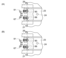
- FIG. 11 is a cross-sectional view showing an enlarged part of the arm mechanism 3.
- FIG. 11 in order to smoothly fit one end of the first stopper 55 into the first recess 64 (see FIG. 3), a third recess 66 is formed in the spacer 23 as shown in FIG.
- a first fixed plunger 67 is provided on one support member 21 .
- the first fixed plunger 67 is fixed to the first support member 21 and includes a first cylinder 68 that opens toward the spacer 23, a spring 69 that is arranged in the first cylinder 68, and a spring 69 that faces the spacer 23. and a first ball 70 attached to the end of the .
- the third recess 66 is formed at a position facing the first ball 70 . As shown in FIG.
- one end of the first stopper 55 is not fitted into the first concave portion 64, so that the large-diameter wheel arm 10 does not rotate together with the cam arm 9.
- the movement of the large-diameter wheel arm 10 can be stopped by fitting the first ball 70 into the third recess 66 due to the elasticity of the spring 69 .
- the cam arm 9 extends in the same straight line as the large-diameter wheel arm 10
- the first cam 53 presses the first stopper 55 , causing one end of the first stopper 55 to move. can be smoothly fitted into the first concave portion 64 .
- the spacer 23 is formed with a fourth recess 90 as shown in FIG.
- the member 29 is provided with a second fixed plunger 91 .
- the second fixed plunger 91 is fixed to the second support member 29 and includes a second cylinder 92 that opens toward the spacer 23, a spring 94 that is arranged in the second cylinder 92, and a spring 94 that faces the spacer 23. and a second ball 95 attached to the end of the .
- the fourth recess 90 is formed at a position facing the second ball 95 . As shown in FIG.
- one end of the second stopper 56 is not fitted into the second concave portion 65, so that while the small-diameter wheel arm 11 is not rotating together with the cam arm 9, as shown in FIG. ), the movement of the small-diameter wheel arm 11 can be stopped by fitting the second ball 95 into the fourth recess 90 due to the elasticity of the spring 94 .
- the cam arm 9 extends on the same straight line as the small-diameter wheel arm 11
- the second stopper 56 is pressed by the second cam 54, and one end of the second stopper 56 is pushed. It can be smoothly fitted into the second concave portion 65 .
- the second stepping motor 50 is supported by the first support member 21, and the second motor shaft 49 is connected to the base end of the first joint body 25 (Figs. 2 and 5).
- the second motor shaft 49 By rotating the second motor shaft 49 forward, the first joint 25 and the second joint 26 are straightened, and the pressure of the second joint 26 causes the first rod 27 and the first elastic member 28 to generate electricity. It moves to the machine 4 side (Fig. 5(B)).
- the large-diameter wheel arm 10 is extended.
- the second motor shaft 49 in the reverse direction the first joint 25 and the second joint 26 are bent, and the first rod 27 and the first elastic member 28 are pulled by the second joint 26 to form a cam. It moves to the device 2 side (Fig. 5(A)).
- the large-diameter wheel arm 10 is contracted.
- the third stepping motor 52 is supported by the second support member 29, and the third motor shaft 51 is connected to the base end of the third joint 31 (Figs. 2 and 6).
- the third motor shaft 51 By rotating the third motor shaft 51 forward, the third joint 31 and the fourth joint 32 are straightened, and the pressure of the fourth joint 32 causes the second rod 33 and the second elastic member 34 to generate electricity. It moves to the machine 4 side (Fig. 6(B)).
- the small-diameter wheel arm 11 is extended.
- the third motor shaft 51 in the reverse direction the third joint 31 and the fourth joint 32 are bent, and the pulling of the fourth joint 32 causes the second rod 33 and the second elastic member 34 to become cams. It moves to the device 2 side (Fig. 6(A)).
- the small-diameter wheel arm 11 is contracted.
- the rotation sensor 59 is installed in the generator 4 and measures the rotation speed of the rotor 44 (Fig. 1) (the number of rotations of the rotor 44 per unit time).
- a known optical sensor or ultrasonic sensor can be used as the rotation sensor 59 .
- the position sensor 60 detects when the cam arm 9 reaches the rotation start position (FIGS. 8 and 9) in the first direction and when the cam arm 9 reaches the rotation start position (FIGS. 8 and 9) in the second direction. ) can be detected.
- the position sensor 60 an optical sensor or a sensor that can specify the position of the cam arm by contacting the limit switch with the cam arm can be used.
- the control device 61 is, for example, a small computer provided on a control panel (not shown) of the power generation system 1.
- the control device 61 includes a CPU, memory, interface, and input device.
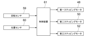
- the control device 61 is connected to the rotation sensor 59, the position sensor 60, and the first, second, and third stepping motors 48, 50, 52 via an interface. and to rotate the first, second and third motor shafts 47, 49 and 51 forward and backward, respectively.
- control device 61 performs the processing shown in FIG. 12 by executing the program stored in the memory by the CPU.
- the cam member 7 is rotated by water power or wind power
- the cam 6 comes into contact with the arm mechanism 3, and the arm mechanism 3 is sequentially rotated in the first direction and the second direction.
- it is started in response to execution of a predetermined operation on the input section of the control device 61 .
- the processing of S1 to S5 in FIG. 12 implements the above-described first mode operation
- the processing of S7 to S11 in FIG. 12 implements the above-described second mode operation.
- the processing shown in FIG. 12 will be described below.
- the control device 61 causes the first motor shaft 47 of the first stepping motor 48 to rotate forward in response to a predetermined operation being performed on the input section (S1). Thereby, as shown in FIG. , 11, only the large-diameter wheel arm 10 rotates together with the cam arm 9 in the first direction, then reverses and rotates in the second direction (FIG. 8).
- the control device 61 controls the period from when the second motor shaft 49 was reversely rotated last time to when the second motor shaft 49 is reversely rotated this time (between S5 of the previous time and S5 of this time). ), it is determined whether or not the rotation sensor 59 has detected that the rotation speed of the rotor 44 has increased to the first value (S6). While the rotational speed of the rotating body 44 has not increased to the first value, the control device 61 determines NO in S6 and repeats S2 to S6. During each of S3 to S5 (while the large-diameter wheel arm 10 rotates in the second direction), the first elastic member 28 of the large-diameter wheel arm 10 contacts the large-diameter wheel 42. (Fig. 4).
- the control device 61 determines YES in S6, and the first stepping motor The first motor shaft 47 of 48 is rotated in reverse (S7).
- S7 the first motor shaft 47 of 48 is rotated in reverse.
- one end of the first stopper 55 is disengaged from the first recess 64 and one end of the second stopper 56 is fitted into the second recess 65 . 11, only the small-diameter wheel arm 11 rotates together with the cam arm 9 in the first direction, then reverses and rotates in the second direction (FIG. 9).
- the control device 61 rotates the third stepping motor 52.
- the third motor shaft 51 is rotated forward (S9).
- the small-diameter wheel arm 11 rotates in the second direction, the small-diameter wheel arm 11 is in an extended state (FIG. 6B), and the second elastic member of the small-diameter wheel arm 11 34 contacts the small diameter wheel 41 .
- the control device 61 rotates the third stepping motor 52.
- the third motor shaft 51 is rotated in reverse (S11).
- the small-diameter wheel arm 11 rotates in the first direction
- the small-diameter wheel arm 11 is in a contracted state (FIG. 6A) and does not come into contact with the rotating small-diameter wheel 41 ( Figure 9). This prevents the rotation speed of the rotor 44 (FIG. 1) from decreasing.
- the control device 61 controls the period from when the third motor shaft 51 was reversely rotated last time to when the third motor shaft 51 is reversely rotated this time (between S11 of the previous time and S11 of this time). ), it is determined whether or not the rotation sensor 59 has detected that the rotation speed of the rotor 44 has decreased to the second value (S12). While the rotation speed of the rotating body 44 has not decreased to the second value, the control device 61 determines NO in S12 and repeats S8 to S12. 11 rotates in the second direction), the second elastic member 34 of the small-diameter wheel arm 11 contacts the small-diameter wheel 41 . In this interval, the rotation speed of the rotating body 44 is maintained or increased due to the small outer diameter of the wheel with which the arm mechanism 3 contacts.
- the control device 61 determines YES in S12 and returns to S1.
- the first motor shaft 47 of the first stepping motor 48 is rotated forward, one end of the second stopper 56 is disengaged from the second recess 65, and one end of the first stopper 55 is fitted into the first recess 64.
- the large-diameter wheel arm 10 rotates together with the cam arm 9 in the first direction, then reverses and rotates in the second direction. is executed.
- the operation in the first mode of bringing the arm mechanism 3 into contact with the large-diameter wheel 42 is performed until the rotation speed of the rotating body 44 rises to the first value.
- a large torque can be applied to the rotating body 44 until the rotational speed of the rotating body 44 rises to the first value.
- the arm mechanism 3 is shifted to the operation of the second mode in which the small-diameter wheel 41 is brought into contact with the arm mechanism 3 .
- the outer diameter of the wheel with which the arm mechanism 3 is brought into contact is reduced (i.e., the wheel with which the arm mechanism 3 is brought into contact is replaced with a large-diameter wheel). 42 to a smaller diameter wheel 41), the speed of rotation of the rotor 44 can be maintained or increased.
- the amount of power generated by the generator 4 can be increased and the amount of power generated by the generator 4 can be maintained.
- a first moving body 72 shown in FIG. 13 is used instead of the first moving body 22 shown in FIG. 5, and a second moving body 87 shown in FIG. 14 is used instead of the second moving body 30 shown in FIG. (i.e., the large-diameter wheel arm 10 comprises a first support member 21 and a first moving body 72 shown in FIG. 13, the small-diameter wheel arm 11 comprises a second support member 29, and the second moving body 87 shown in FIG. 14).
- the first moving body 72 includes a first joint body 73, a second joint body 74, a first absorber 75, a first rod 76, and a first elastic member 77.
- the first rod 76 is movably supported by the first support member 21 .
- the first absorber 75 comprises a first cylinder 78 having an opening at its tip and a first spring 79 arranged inside the first cylinder 78 .
- the distal end portion of the first joint body 73 and the proximal end portion of the second joint body 74 are hinged, and the distal end portion of the second joint body 74 and the proximal end portion of the first cylinder 78 are connected. They are hinged, the proximal end of the first spring and the proximal end of the first cylinder 78 are connected, and the distal end of the first spring 79 and the proximal end of the first rod 76 are connected.
- the first elastic member 77 extends from the tip of the first rod 76 and constitutes the tip of the large-diameter wheel arm 10 .
- a second motor shaft 49 of the second stepping motor 50 is connected to the base end of the first joint body 73 .
- the second moving body 87 includes a third joint 80, a fourth joint 81, a second absorber 82, a second rod 83, and a second elastic member 84.
- the second rod 83 is movably supported by the second support member 29 .
- the second absorber 82 includes a second cylinder 85 having an opening at its tip and a second spring 86 arranged inside the second cylinder 85 .
- the distal end of the third joint 80 and the proximal end of the fourth joint 81 are hinged, and the distal end of the fourth joint 81 and the proximal end of the second cylinder 85 are connected. It is hinged, and the distal end of the second spring 86 and the proximal end of the second rod 83 are connected.
- the second elastic member 84 extends from the tip of the second rod 83 and constitutes the tip of the small-diameter wheel arm 11 .
- a third motor shaft 51 of the third stepping motor 52 is connected to the base end of the third joint body 80 .
- the operation control means moves the large-diameter wheel arm 10 Let it be in an extended state (FIGS. 8 and 13(B)). This is because when the position sensor 60 detects that the cam arm 9 has reached the rotation start position in the second direction (YES in S2 of FIG. 12), the control device 61 causes the second stepping motor 50 to rotate. By rotating the second motor shaft 49 forward (S3 in FIG.
- the first joint body 73 and the second joint body 74 become linear, and the first cylinder 78, the first spring 79, the first This is achieved by moving the rod 76 and the first elastic member 77 toward the generator 4 (left side in FIG. 13) (FIG. 13(B)).
- the first elastic member 77 contacts the large-diameter wheel 42 (FIG. 8).
- the operation control means causes the large-diameter wheel arm 10 to contract (FIGS. 8 and 13(A)).
- the control device 61 causes the second stepping motor 50 to rotate.
- the second motor shaft 49 By rotating the second motor shaft 49 in reverse (S5 in FIG. 12), the first joint 73 and the second joint 74 are bent, and the first cylinder 78, the first spring 79, the first rod 76 and the first elastic member 77 are realized by moving toward the cam device 2 (right side in FIG. 13) (FIG. 13(A)).
- the first elastic member 77 does not come into contact with the large-diameter wheel 42 while the large-diameter wheel arm 10 rotates in the first direction (FIG. 8).
- the operation control means causes the small-diameter wheel arm 11 to extend (FIGS. 9 and 14(B)).
- the control device 61 causes the third stepping motor 52 to rotate.
- the third motor shaft 51 forward (S9 in FIG. 12)
- the third joint 80 and the fourth joint 81 become linear
- the second cylinder 84, the second spring 84, the second rod 83 and the second elastic member 84 are realized by moving to the generator 4 side (left side in FIG. 14) (FIG. 14(B)).
- the first elastic member 77 contacts the large-diameter wheel 42 (FIG. 9).
- the operation control means causes the small-diameter wheel arm 11 to contract (FIGS. 9 and 14(A)).
- the control device 61 causes the third stepping motor 52 to rotate.
- the third motor shaft 51 By rotating the third motor shaft 51 in the reverse direction (S11 in FIG. 12), the third joint 80 and the fourth joint 81 are bent, and the second spring 84 pulls the second rod 83 and This is realized by moving the second elastic member 84 toward the cam device 2 (right side in FIG. 14) (FIG. 14(A)).
- the second elastic member 84 does not contact the small-diameter wheel 41 while the small-diameter wheel arm 11 rotates in the first direction (FIG. 9).
- FIG. 13C shows the first moving body 72 when the first elastic member 77 is strongly pressed against the large-diameter wheel 42.
- 14(C) shows the state of the second moving body 87 when the second elastic member 84 is strongly pressed against the small-diameter wheel 41).
- the large-diameter wheel 42 is provided below the small-diameter wheel 41, and the large-diameter wheel arm 10 is provided below the small-diameter wheel arm 11.
- the diameter wheel 42 may be provided above the small-diameter wheel 41 and, accordingly, the large-diameter wheel arm 10 may be provided above the small-diameter wheel arm 11 .
- the main shaft 12 sequentially passes through the inner side of the coil spring 36 and the inner side of the annular plate 37, and then the lower plate 17 and the base end portion 29a of the second support member 29 (corresponding to the base end portion of the small-diameter wheel arm 11). , the spacer 23, the base end portion 21a of the first support member 21 (corresponding to the base end portion of the large-diameter wheel arm 10), and the upper plate 16 in this order.
- the spacer 23 is provided between the base end portion of the large-diameter wheel arm and the base end portion of the small-diameter wheel arm. good.
- the third recess 66, the first fixed plunger 67, the fourth recess 90, and the second fixed plunger 91 shown in FIG. 11 are also omitted, but these configurations are omitted.
- the first stopper 55 is pressed by the first cam 53 to fit one end of the first stopper 55 into the first concave portion 64, or as shown in FIG. , it is possible to fit one end of the second stopper 56 into the second concave portion 65 by pressing the second stopper 56 by the second cam 54 .
- the base end portion of the cam arm 9 is configured by the main shaft penetrating member 14, but the structure of the base end portion of the cam arm 9 can also realize the functions of the present invention described above. can be modified into various structures. Even if the structure of the base end portion of the cam arm 9 is changed, or if the spacer 23 is omitted as described above, the main shaft 12 can be connected to the base end portion of the cam arm 9 and the large-diameter wheel arm 10 . By passing through the base end portion 21a and the base end portion 29a of the small-diameter wheel arm 11, the cam arm 9, the large-diameter wheel arm 10, and the small-diameter wheel arm 11 can be rotated in the same manner as described above. can be generated.
- one main shaft 12 is connected to the base end portion of the cam arm 9 (the main shaft penetrating member 14), the base end portion 21a of the large-diameter wheel arm 10, and the base end portion of the small-diameter wheel arm 11. 29 a is shown, but the shaft penetrating the base end of the cam arm 9 , the shaft penetrating the base end 29 a of the small-diameter wheel arm 11 , and the base end of the large-diameter wheel arm 10 21a may be provided separately.
- the arm mechanism 3 includes the large-diameter wheel arm 10 as the arm for contacting the large-diameter wheel 42, and the small-diameter wheel arm 11 as the arm for contacting the small-diameter wheel 41.
- one arm may be brought into contact with the large-diameter wheel 42 and the small-diameter wheel 41 .
- the motion control means moves the arm in response to the rotational speed of the rotating body 44 increasing to the first value while operating in the first mode in which the arm contacts the large-diameter wheel 42.
- the arm By moving the arm to the position facing the small-diameter wheel 41, the arm is shifted to the second mode of operation in which the arm contacts the small-diameter wheel 41, and while the arm is operating in the second mode, the rotation speed of the rotating body 44 reaches the first value.
- the operation in the first mode is performed.
- biasing means provided in the power generation system of the present invention is not limited to the biasing means 13 shown in the above embodiment.
- the power generation system of the present invention may comprise, for example, biasing means 100 shown in FIG.
- the biasing means 100 includes a base plate 101, a first coil spring 102 arranged on the base plate 101, a first annular plate 103 supported by the upper end of the first coil spring 102, and a first annular plate 103.
- a first roller 104 rotatably attached to the upper surface, a first guide rod 105, a top plate 106, a second coil spring 107 arranged under the top plate 106, and supported by the lower end of the second coil spring 107.
- a second annular plate 108 , a second roller 109 rotatably attached to the lower surface of the second annular plate 108 , and a second guide rod 110 .
- the base plate 101 , first coil spring 102 , first annular plate 103 , first roller 104 and first guide rod 105 are arranged below the lower plate 17 .
- the top plate 106 , the second coil spring 107 , the second annular plate 108 , the second roller 109 and the second guide rod 110 are arranged above the top plate 16 .
- the main shaft 12 has its lower end joined to the base plate 101 and its upper end joined to the top plate 106 .
- the main shaft 12 extends upward from the base plate 101, passes through the inner side of the first coil spring 102 and the inner side of the first annular plate 103 sequentially, and then the lower plate 17 and the base end portion 21a ( (corresponding to the base end portion of the large-diameter wheel arm 10), the spacer 23, the base end portion 29a of the second support member 29 (corresponding to the base end portion of the small-diameter wheel arm 11), and the upper plate 16 sequentially. Then, it passes through the inner side of the second annular plate 108 and the inner side of the second coil spring 107 in order to reach the top plate 106 .
- the spacer 23 is fixed to the main shaft 12 by inserting the fixing pin 24 into the main shaft 12 through the spacer 23 in the same manner as in the above embodiment.
- a first convex portion 121 having a first tapered surface 120 is formed on the lower surface of the lower plate 17 (FIGS. 16(B) and 17(B)), and the first tapered surface 120 becomes Slanted in a second direction.
- a second convex portion 123 having a second tapered surface 122 is formed on the upper surface of the upper plate 16 (FIGS. 16A and 17A). Slanted in a second direction.
- the first tapered surface 120 presses the first roller 104 due to the rotation of the first protrusion 121 in the first direction. Then, the first roller 104 rolls from the upper side to the lower side of the first tapered surface 120, and the first annular plate 103 applies downward force to the first coil spring 102, and the first coil spring 102 is compressed. (from the state of FIG. 16(B) to the state of FIG. 17(B)), and the rotation of the second convex portion 123 in the first direction causes the second tapered surface 122 to move toward the second roller.
- the two-coil spring 107 is in a compressed state (from the state in FIG. 16(A) to the state in FIG. 17(A)).
- the first guide rod 105 guides the vertical movement of the first annular plate 103 and is provided outside the first coil spring 102 .
- the first guide rod 105 extends upward from the base plate 101 and penetrates the first annular plate 103.
- a first bolt 130 is attached to the upper end of the first guide rod 105 extending from the first annular plate 103. is concluded.
- the first coil spring 102 applies an upward force to the first annular plate 103 due to the elastic return of the first coil spring 102 , the first annular plate 103 comes into contact with the first bolt 130 , thereby causing the first annular plate 103 to Stop (FIG. 16(B) shows a state in which the first annular plate 103 is in contact with the first bolt 130).
- the second guide rod 110 guides the vertical movement of the second annular plate 108 and is provided outside the second coil spring 107 .
- the second guide rod 110 extends downward from the top plate 106 and penetrates the second annular plate 108.
- a second bolt 131 is attached to the lower end of the second guide rod 110 extending from the second annular plate 108. is concluded.
- the force of the two coil springs 102 and 107 acts on the cam arm 9, so that even if the rotation resistance of the rotating body 44 of the generator 4 is large, Contact between the large-diameter wheel arm 10 and the large-diameter wheel 42 or contact between the small-diameter wheel arm 11 and the small-diameter wheel 41 rotates the rotating body 44, thereby causing the generator 4 to generate power. be able to.
- the first guide rod 105 and the second guide rod 110 are not necessarily required and may be omitted.
- the large-diameter wheel 42 may be provided above the small-diameter wheel 41, and the large-diameter wheel arm 10 may be provided above the small-diameter wheel arm 11.
- the main shaft 12 extends upward from the base plate 101, passes through the inner side of the first coil spring 102 and the inner side of the first annular plate 103 in sequence, and then the lower plate 17 and the base end of the first support member 21.
Landscapes
- Engineering & Computer Science (AREA)
- General Engineering & Computer Science (AREA)
- Mechanical Engineering (AREA)
- Chemical & Material Sciences (AREA)
- Combustion & Propulsion (AREA)
- Life Sciences & Earth Sciences (AREA)
- Sustainable Development (AREA)
- Sustainable Energy (AREA)
- Power Engineering (AREA)
- Transmission Devices (AREA)
- Connection Of Motors, Electrical Generators, Mechanical Devices, And The Like (AREA)
Abstract
Description
前記カム部材の回転中に前記カムが接触することで回動を生じるアーム機構と、 小径ホイールと、これよりも外径の大きい大径ホイールとが回転軸に取り付けられた回転体を備え、前記アーム機構の回動中に前記アーム機構が前記小径ホイール及び前記大径ホイールのいずれかの外周面に接触することで、前記回転体の回転が生じて、前記回転体の回転エネルギーを電気エネルギーに変換することで発電を行う発電機と、
前記アーム機構を前記大径ホイールに接触させる第一モードで動作している間に、前記回転体の回転速度が第一値に上昇したことに応じて、前記アーム機構を前記小径ホイールに接触させる第二モードの動作に移行し、前記第二モードで動作している間に、前記回転体の回転速度が前記第一値以下である第二値に減少したことに応じて、前記第一モードの動作に移行する動作制御手段とを備える、発電システム。
前記主軸は、前記カム用アームの基端部、前記小径ホイール用アームの基端部、及び前記大径ホイール用アームの基端部を貫通しており、
前記カム部材の回転で前記カムが前記カム用アームの先端部に接触するたびに、前記カム用アームには、前記カムの押圧によって、前記主軸回りの第一方向への回動が生じ、
前記付勢手段は、前記カム用アームが前記第一方向に回動するたびに、前記第一方向とは逆の第二方向に前記カム用アームを付勢するものであり、当該付勢手段による付勢によって、前記カム用アームは、前記第一方向に回動した後、反転して、前記第二方向に回動し、
前記動作制御手段は、
前記第一モードの動作として、
前記大径ホイール用アーム及び前記小径ホイール用アームのうち、前記大径ホイール用アームのみを、前記カム用アームと共に、前記第一方向に回動した後、反転して、前記第二方向に回動するものとし、且つ、前記大径ホイール用アームが前記第一方向に回動する間では、前記大径ホイール用アームを縮めた状態とすることで、前記大径ホイール用アームを前記大径ホイールに接触させず、前記大径ホイール用アームが前記第二方向に回動する間では、前記大径ホイール用アームを伸びた状態とすることで、前記大径ホイール用アームを前記大径ホイールに接触させ、
前記第二モードの動作として、
前記大径ホイール用アーム及び前記小径ホイール用アームのうち、前記小径ホイール用アームのみを、前記カム用アームと共に、前記第一方向に回動した後、反転して、前記第二方向に回動するものとし、且つ、前記小径ホイール用アームが前記第一方向に回動する間では、前記小径ホイール用アームを縮めた状態とすることで、前記小径ホイール用アームを前記小径ホイールに接触させず、前記小径ホイール用アームが前記第二方向に回動する間では、前記小径ホイール用アームを伸びた状態とすることで、前記小径ホイール用アームを前記小径ホイールに接触させる項1に記載の発電システム。
前記主軸貫通部材は、上板と、前記上板の下方に間隔をあけて配置される下板と、上下方向に延びて前記上板の中間部と前記下板の中間部とを繋ぐ連結板とを備え、
前記カム用アーム本体は、前記連結板から前記カム装置側に延びており、
前記小径ホイール用アームの基端部及び前記大径ホイール用アームの基端部は、前記上板と前記下板の間における前記連結板よりも前記発電機側の空間に配置され、
前記付勢手段は、ベース板と、前記ベース板の上に配置されるコイルバネと、前記コイルバネの上端部に支持される環状板と、前記環状板の上面に回転可能に取り付けられるローラーとを備えるものであって、前記ベース板、前記コイルバネ、前記環状板、及び前記ローラーは、前記下板の下側に配置されており、
前記主軸は、前記ベース板から上方に延びており、前記コイルバネの内側及び前記環状板の内側を順次通過した後、前記下板、前記大径ホイール用アームの基端部、前記主軸に固定されるスぺーサ、前記小径ホイール用アームの基端部、及び前記上板を順次貫通し、或いは、前記コイルバネの内側及び前記環状板の内側を順次通過した後、前記下板、前記小径ホイール用アームの基端部、前記主軸に固定されるスぺーサ、前記大径ホイール用アームの基端部、及び前記上板を順次貫通しており、
前記下板の下面には、テーパ面を有する凸部が形成されており、前記テーパ面は、下側になるほど前記第二方向に傾斜しており、
前記カム用アームが前記第一方向に回動する間では、前記第一方向への前記凸部の回動により前記テーパ面が前記ローラーを押圧することで、前記テーパ面の上側から下側へ向かう前記ローラーの転動が生じて、前記環状板から前記コイルバネに下向きの力が加えられて、前記コイルバネが圧縮された状態になり、この後、前記コイルバネの弾性復帰により前記コイルバネから前記環状板に上向きの力が加えられて、前記ローラーが前記テーパ面を押圧して前記カム用アームを前記第二方向に付勢するものとなることで、前記カム用アームが、前記第一方向から反転して、前記第二方向に回動し、これに伴い、前記テーパ面の下側から上側に向かう前記ローラーの転動が生じる、項2に記載の発電システム。
前記第一カム及び前記第二カムは前記第一モータ軸に間隔をあけて取り付けられるものであって、前記第一ステッピングモータは、前記第一モータ軸が前記上板と前記下板との間における前記連結板よりも前記カム装置側の空間を上下方向に延びて、前記第一カムが前記大径ホイール用アームの基端部と相対し、前記第二カムが前記小径ホイール用アームの基端部と相対するように、前記上板又は前記下板に支持され、
前記第一ストッパーは、前記大径ホイール用アームの基端部と前記第一カムとの間で移動可能に前記連結板の第一貫通孔に通されており、
前記第一ストッパーバネは、前記第一ストッパーが内側を通過するコイルバネであり、前記第一ストッパーの外周から突出する第一鍔部と前記連結板との間に挟み込まれており、
前記第二ストッパーは、前記小径ホイール用アームの基端部と前記第二カムとの間で移動可能に前記連結板の第二貫通孔に通されており、
前記第二ストッパーバネは、前記第二ストッパーが内側を通過するコイルバネであり、、前記第二ストッパーの外周から突出する第二鍔部と前記連結板との間に挟み込まれており、
前記大径ホイール用アームの基端部には、前記第一ストッパーの一端部を嵌合させるための第一凹部が形成されており、
前記小径ホイール用アームの基端部には、前記第二ストッパーの一端部を嵌合させるための第二凹部が形成されており、
前記第一ステッピングモータの前記第一モータ軸が正回転することで、前記第一カムが前記第一ストッパーを前記大径ホイール用アーム側に押圧して、前記第一ストッパーバネが圧縮されて、前記第一ストッパーの一端部が前記第一凹部に嵌合し、且つ、前記第二カムによる前記第二ストッパーの押圧が解除されて、前記第二ストッパーバネが弾性復帰し、前記第二ストッパーの一端部が前記第二凹部から外れた状態になり、
前記第一ステッピングモータの前記第一モータ軸が逆回転することで、前記第一カムによる前記第一ストッパーの押圧が解除されて、前記第一ストッパーバネが弾性復帰して、前記第一ストッパーの一端部が前記第一凹部から外れ、且つ、前記第二カムが前記第二ストッパーを前記小径ホイール用アーム側に押圧して、前記第二ストッパーバネが圧縮して、前記第二ストッパーの一端部が前記第二凹部に嵌合した状態になり、
前記回転センサは、前記回転体の回転速度を検知可能であり、
前記制御装置の入力部に所定の操作が行われることに応じて、前記制御装置が前記第一ステッピングモータの前記第一モータ軸を正回転させることで、前記第二ストッパーの一端部が前記第二凹部から外れた状態になって、前記大径ホイール用アームが、前記カム用アームと共に、第一方向に回動した後、反転して、第二方向に回動するものとなり、
前記回転体の回転速度が前記第一値に上昇したことが前記回転センサに検知されることに応じて、前記制御装置が前記第一ステッピングモータの前記第一モータ軸を逆回転させることで、前記第二ストッパーの一端部が前記第二凹部に嵌合した状態になって、前記小径ホイール用アームが、前記カム用アームと共に、前記第一方向に回動した後、反転して、前記第二方向に回動するものとなり、
前記回転体の回転速度が前記第二値に減少したことが前記回転センサに検知されることに応じて、前記制御装置が前記第一ステッピングモータの前記第一モータ軸を正回転させることで、前記第二ストッパーの一端部が前記第二凹部から外れた状態になって、前記大径ホイール用アームが、前記カム用アームと共に、第一方向に回動した後、反転して、第二方向に回動するものとなる項3に記載の発電システム。
前記第一支持部材の基端部は、前記大径ホイール用アームの基端部を構成し、
前記第一移動体は、第一節体と、第二節体と、第一ロッドと、第一弾性部材とを備え、前記第一節体の先端部と前記第二節体の基端部とがヒンジ連結され、前記第二節体の先端部と前記第一ロッドの基端部とがヒンジ連結され、前記第一ロッドが前記第一支持部材に移動可能に支持され、前記第一弾性部材は、前記第一ロッドの先端部から延びるものであって、前記大径ホイール用アームの先端部を構成しており、
前記小径ホイール用アームは、第二支持部材と、第二移動体とを備え、
前記第二支持部材の基端部は、前記小径ホイール用アームの基端部を構成し、
前記第二移動体は、第三節体と、第四節体と、第二ロッドと、第二弾性部材とを備え、前記第三節体の先端部と前記第四節体の基端部とがヒンジ連結され、前記第四節体の先端部と前記第二ロッドの基端部とがヒンジ連結され、前記第二ロッドが前記第二支持部材に移動可能に支持され、前記第二弾性部材は、前記第二ロッドの先端部から延びるものであって、前記小径ホイール用アームの先端部を構成しており、
前記動作制御手段は、第二モータ軸を有する第二ステッピングモータと、第三モータ軸を有する第三ステッピングモータと、位置センサとを、さらに備え、
前記第二ステッピングモータは、前記第一支持部材に支持されており、前記第二モータ軸は、前記第一節体の基端部に接続されており、
前記第三ステッピングモータは、前記第二支持部材に支持されており、前記第三モータ軸は、前記第三節体の基端部に接続されており、
前記位置センサは、前記カム用アームが、前記第一方向の回動開始位置に到達したことや、前記第二方向の回動開始位置に到達したことを検知可能であり、
前記大径ホイール用アームが前記第二方向に回動する間に、前記動作制御手段が前記大径ホイール用アームを伸びた状態とすることは、前記カム用アームが前記第二方向の回動開始位置に到達したことが前記位置センサに検知されたことに応じて、前記制御装置が前記第二ステッピングモータの前記第二モータ軸を正回転させることで、前記第一節体及び前記第二節体が直線状になって、前記第二節体の押圧で前記第一ロッド及び前記第一弾性部材が前記発電機側に移動することで実現され、前記大径ホイール用アームが前記第二方向に回動する間では、前記第一弾性部材が前記大径ホイールに接触し、
前記大径ホイール用アームが前記第一方向に回動する間に、前記動作制御手段が前記大径ホイール用アームを縮めた状態とすることは、前記カム用アームが前記第一方向の回動開始位置に到達したことが前記位置センサに検知されたことに応じて、前記制御装置が前記第二ステッピングモータの前記第二モータ軸を逆回転させることで、前記第一節体及び前記第二節体が屈曲状になって、前記第二節体の牽引で前記第一ロッド及び前記第一弾性部材が前記カム部材側に移動することで実現され、前記大径ホイール用アームが前記第一方向に回動する間では、前記第一弾性部材が前記大径ホイールに接触せず、
前記小径ホイール用アームが前記第二方向に回動する間に、前記動作制御手段が前記小径ホイール用アームを伸びた状態とすることは、前記カム用アームが前記第二方向の回動開始位置に到達したことが前記位置センサに検知されたことに応じて、前記制御装置が前記第三ステッピングモータの前記第三モータ軸を正回転させることで、前記第三節体及び前記第四節体が直線状になって、前記第四節体の押圧で前記第二ロッド及び前記第二弾性部材が前記発電機側に移動することで実現され、前記小径ホイール用アームが前記第二方向に回動する間では、前記第二弾性部材が前記小径ホイールに接触し、
前記小径ホイール用アームが前記第一方向に回動する間に、前記動作制御手段が前記小径ホイール用アームを縮めた状態とすることは、前記カム用アームが前記第一方向の回動開始位置に到達したことが前記位置センサに検知されたことに応じて、前記制御装置が前記第三ステッピングモータの前記第三モータ軸を逆回転させることで、前記第三節体及び前記第四節体が屈曲状になって、前記第四節体の牽引で前記第二ロッド及び前記第二弾性部材が前記カム部材側に移動することで実現され、前記小径ホイール用アームが前記第一方向に回動する間では、前記第二弾性部材が前記小径ホイールに接触しない項3又は4に記載の発電システム。
前記第一支持部材の基端部は、前記大径ホイール用アームの基端部を構成し、
前記第一移動体は、第一節体と、第二節体と、第一アブソーバーと、第一ロッドと、第一弾性部材とを備えて、前記第一ロッドが前記第一支持部材に移動可能に支持されており、
前記第一アブソーバーは、先端に開口を有する第一シリンダーと、前記第一シリンダーの内部に配置される第一バネとを備えており、前記第一節体の先端部と前記第二節体の基端部とがヒンジ連結され、前記第二節体の先端部と前記第一シリンダーの基端部とがヒンジ連結され、前記第一バネの基端部と前記第一シリンダーの基端部とが接続され、前記第一バネの先端部と前記第一ロッドの基端部とが接続され、前記第一弾性部材は、前記第一ロッドの先端部から延びて、前記大径ホイール用アームの先端部を構成しており、
前記小径ホイール用アームは、第二支持部材と、第二移動体とを備え、
前記第二支持部材の基端部は、前記小径ホイール用アームの基端部を構成し、
前記第二移動体は、第三節体と、第四節体と、第二アブソーバーと、第二ロッドと、第二弾性部材とを備えて、前記第二ロッドが前記第二支持部材に移動可能に支持されたものであって、
前記第二アブソーバーは、先端に開口を有する第二シリンダーと、前記第二シリンダーの内部に配置される第二バネとを備えており、前記第三節体の先端部と前記第四節体の基端部とがヒンジ連結され、前記第四節体の先端部と前記第二シリンダーの基端部とがヒンジ連結され、前記第二バネの先端部と前記第二ロッドの基端部とが接続され、前記第二弾性部材は、前記第二ロッドの先端部から延びて、前記小径ホイール用アームの先端部を構成しており、
前記動作制御手段は、第二モータ軸を有する第二ステッピングモータと、第三モータ軸を有する第三ステッピングモータと、位置センサとを、さらに備え、
前記第二ステッピングモータは、前記第一支持部材に支持されており、前記第二モータ軸は、前記第一節体の基端部に接続されており、
前記第三ステッピングモータは、前記第二支持部材に支持されており、前記第三モータ軸は、前記第三節体の基端部に接続されており、
前記位置センサは、前記カム用アームが、前記第一方向の回動開始位置に到達したことや、前記第二方向の回動開始位置に到達したことを検知可能であり、
前記大径ホイール用アームが前記第二方向に回動する間に、前記動作制御手段が前記大径ホイール用アームを伸びた状態とすることは、前記カム用アームが前記第二方向の回動開始位置に到達したことが前記位置センサに検知されたことに応じて、前記制御装置が前記第二ステッピングモータの前記第二モータ軸を正回転させることで、前記第一節体及び前記第二節体が直線状になって、前記第一シリンダー、前記第一バネ、前記第一ロッド、及び前記第一弾性部材が、前記発電機側に移動することで実現され、前記大径ホイール用アームが前記第二方向に回動する間では、前記第一弾性部材が前記大径ホイールに接触し、
前記大径ホイール用アームが前記第一方向に回動する間に、前記動作制御手段が前記大径ホイール用アームを縮めた状態とすることは、前記カム用アームが前記第一方向の回動開始位置に到達したことが前記位置センサに検知されたことに応じて、前記制御装置が前記第二ステッピングモータの前記第二モータ軸を逆回転させることで、前記第一節体及び前記第二節体が屈曲状になって、前記第一シリンダー、前記第一バネ、前記第一ロッド、及び前記第一弾性部材が、前記カム用ホイール側に移動することで実現され、前記大径ホイール用アームが前記第一方向に回動する間では、前記第一弾性部材が前記大径ホイールに接触せず、
前記小径ホイール用アームが前記第二方向に回動する間に、前記動作制御手段が前記小径ホイール用アームを伸びた状態とすることは、前記カム用アームが前記第二方向の回動開始位置に到達したことが前記位置センサに検知されたことに応じて、前記制御装置が前記第三ステッピングモータの前記第三モータ軸を正回転させることで、前記第三節体及び前記第四節体が直線状になって、前記第二シリンダー、前記第二バネ、前記第二ロッド及び前記第二弾性部材が、前記発電機側に移動することで実現され、前記小径ホイール用アームが前記第二方向に回動する間では、前記第二弾性部材が前記小径ホイールに接触し、 前記小径ホイール用アームが前記第一方向に回動する間に、前記動作制御手段が前記小径ホイール用アームを縮めた状態とすることは、前記カム用アームが前記第一方向の回動開始位置に到達したことが前記位置センサに検知されたことに応じて、前記制御装置が前記第三ステッピングモータの前記第三モータ軸を逆回転させることで、前記第三節体及び前記第四節体が屈曲状になって、前記第二シリンダー、前記第二バネ、前記第二ロッド、及び前記第二弾性部材が、前記カム部材側に移動することで実現され、前記小径ホイール用アームが前記第一方向に回動する間では、前記第二弾性部材が前記小径ホイールに接触しない項3又は4に記載の発電システム。
2 カム装置
3 アーム機構
4 発電機
6 カム
7 カム部材
8 主駆動軸
9 カム用アーム
10 大径ホイール用アーム
11 小径ホイール用アーム
12 主軸
13 付勢手段
14 主軸貫通部材
15 カム用アーム本体
15a カム用アーム本体の基端部
16 上板
17 下板
18 連結板
19 上板と下板との間における連結板よりもカム装置側の空間
20 上板と下板との間における連結板よりも発電機側の空間
21 第一支持部材
21a 第一支持部材の基端部
22 第一移動体
23 スペーサ
24 固定ピン
25 第一節体
26 第二節体
27 第一ロッド
28 第一弾性部材
29 第二支持部材
29a 第二支持部材の基端部
30 第二移動体
31 第三節体
32 第四節体
33 第二ロッド
34 第二弾性部材
35 ベース板
36 コイルバネ
37 環状板
38 ローラー
41 小径ホイール
42 大径ホイール
43 回転軸
44 回転体
45 テーパ面
46 凸部
47 第一モータ軸
48 第一ステッピングモータ
49 第二モータ軸
50 第二ステッピングモータ
51 第三モータ軸
52 第三ステッピングモータ
53 第一カム
54 第二カム
55 第一ストッパー
55a 第一鍔部
56 第二ストッパー
56a 第二鍔部
57 第一ストッパーバネ
58 第二ストッパーバネ
59 回転センサ
60 位置センサ
61 制御装置
62 第一貫通孔
63 第二貫通孔
64 第一凹部
65 第二凹部
72 第一移動体
73 第一節体
74 第二節体
75 第一アブソーバー
76 第一ロッド
77 第一弾性部材
78 第一シリンダー
79 第一バネ
80 第三節体
81 第四節体
82 第二アブソーバー
83 第二ロッド
84 第二シリンダー
84 第二バネ
84 第二弾性部材
85 第二シリンダー
86 第二バネ
87 第二移動体
100 付勢手段
101 ベース板
102 第一コイルバネ
103 第一環状板
104 第一ローラー
105 第一ガイド棒
106 トップ板
107 第二コイルバネ
108 第二環状板
109 第二ローラー
120 第一テーパ面
121 第一凸部
122 第二テーパ面
123 第二凸部
Claims (6)
- カムが外周面から突出しているカム部材を備え、水力或いは風力により前記カム部材が回転するカム装置と、
前記カム部材の回転中に前記カムが接触することで回動を生じるアーム機構と、 小径ホイールと、これよりも外径の大きい大径ホイールとが回転軸に取り付けられた回転体を備え、前記アーム機構の回動中に前記アーム機構が前記小径ホイール及び前記大径ホイールのいずれかの外周面に接触することで、前記回転体の回転が生じて、前記回転体の回転エネルギーを電気エネルギーに変換することで発電を行う発電機と、
前記アーム機構を前記大径ホイールに接触させる第一モードで動作している間に、前記回転体の回転速度が第一値に上昇したことに応じて、前記アーム機構を前記小径ホイールに接触させる第二モードの動作に移行し、前記第二モードで動作している間に、前記回転体の回転速度が前記第一値以下である第二値に減少したことに応じて、前記第一モードの動作に移行する動作制御手段とを備える、発電システム。 - 前記アーム機構は、カム用アームと、大径ホイール用アームと、小径ホイール用アームと、主軸と、付勢手段とを備え、
前記主軸は、前記カム用アームの基端部、前記小径ホイール用アームの基端部、及び前記大径ホイール用アームの基端部を貫通しており、
前記カム部材の回転で前記カムが前記カム用アームの先端部に接触するたびに、前記カム用アームには、前記カムの押圧によって、前記主軸回りの第一方向への回動が生じ、
前記付勢手段は、前記カム用アームが前記第一方向に回動するたびに、前記第一方向とは逆の第二方向に前記カム用アームを付勢するものであり、当該付勢手段による付勢によって、前記カム用アームは、前記第一方向に回動した後、反転して、前記第二方向に回動し、
前記動作制御手段は、
前記第一モードの動作として、
前記大径ホイール用アーム及び前記小径ホイール用アームのうち、前記大径ホイール用アームのみを、前記カム用アームと共に、前記第一方向に回動した後、反転して、前記第二方向に回動するものとし、且つ、前記大径ホイール用アームが前記第一方向に回動する間では、前記大径ホイール用アームを縮めた状態とすることで、前記大径ホイール用アームを前記大径ホイールに接触させず、前記大径ホイール用アームが前記第二方向に回動する間では、前記大径ホイール用アームを伸びた状態とすることで、前記大径ホイール用アームを前記大径ホイールに接触させ、
前記第二モードの動作として、
前記大径ホイール用アーム及び前記小径ホイール用アームのうち、前記小径ホイール用アームのみを、前記カム用アームと共に、前記第一方向に回動した後、反転して、前記第二方向に回動するものとし、且つ、前記小径ホイール用アームが前記第一方向に回動する間では、前記小径ホイール用アームを縮めた状態とすることで、前記小径ホイール用アームを前記小径ホイールに接触させず、前記小径ホイール用アームが前記第二方向に回動する間では、前記小径ホイール用アームを伸びた状態とすることで、前記小径ホイール用アームを前記小径ホイールに接触させる請求項1に記載の発電システム。 - 前記カム用アームは、主軸貫通部材と、カム用アーム本体とを備え、前記主軸貫通部材によって、前記カム用アームの基端部が構成されており、
前記主軸貫通部材は、上板と、前記上板の下方に間隔をあけて配置される下板と、上下方向に延びて前記上板の中間部と前記下板の中間部とを繋ぐ連結板とを備え、
前記カム用アーム本体は、前記連結板から前記カム装置側に延びており、
前記小径ホイール用アームの基端部及び前記大径ホイール用アームの基端部は、前記上板と前記下板の間における前記連結板よりも前記発電機側の空間に配置され、
前記付勢手段は、ベース板と、前記ベース板の上に配置されるコイルバネと、前記コイルバネの上端部に支持される環状板と、前記環状板の上面に回転可能に取り付けられるローラーとを備えるものであって、前記ベース板、前記コイルバネ、前記環状板、及び前記ローラーは、前記下板の下側に配置されており、
前記主軸は、前記ベース板から上方に延びており、前記コイルバネの内側及び前記環状板の内側を順次通過した後、前記下板、前記大径ホイール用アームの基端部、前記主軸に固定されるスぺーサ、前記小径ホイール用アームの基端部、及び前記上板を順次貫通し、或いは、前記コイルバネの内側及び前記環状板の内側を順次通過した後、前記下板、前記小径ホイール用アームの基端部、前記主軸に固定されるスぺーサ、前記大径ホイール用アームの基端部、及び前記上板を順次貫通しており、
前記下板の下面には、テーパ面を有する凸部が形成されており、前記テーパ面は、下側になるほど前記第二方向に傾斜しており、
前記カム用アームが前記第一方向に回動する間では、前記第一方向への前記凸部の回動により前記テーパ面が前記ローラーを押圧することで、前記テーパ面の上側から下側へ向かう前記ローラーの転動が生じて、前記環状板から前記コイルバネに下向きの力が加えられて、前記コイルバネが圧縮された状態になり、この後、前記コイルバネの弾性復帰により前記コイルバネから前記環状板に上向きの力が加えられて、前記ローラーが前記テーパ面を押圧して前記カム用アームを前記第二方向に付勢するものとなることで、前記カム用アームが、前記第一方向から反転して、前記第二方向に回動し、これに伴い、前記テーパ面の下側から上側に向かう前記ローラーの転動が生じる、請求項2に記載の発電システム。 - 前記動作制御手段は、第一モータ軸を有する第一ステッピングモータと、第一カムと、第二カムと、第一ストッパーと、第二ストッパーと、第一ストッパーバネと、第二ストッパーバネと、回転センサと、制御装置とを備え、
前記第一カム及び前記第二カムは前記第一モータ軸に間隔をあけて取り付けられるものであって、前記第一ステッピングモータは、前記第一モータ軸が前記上板と前記下板との間における前記連結板よりも前記カム装置側の空間を上下方向に延びて、前記第一カムが前記大径ホイール用アームの基端部と相対し、前記第二カムが前記小径ホイール用アームの基端部と相対するように、前記上板又は前記下板に支持され、
前記第一ストッパーは、前記大径ホイール用アームの基端部と前記第一カムとの間で移動可能に前記連結板の第一貫通孔に通されており、
前記第一ストッパーバネは、前記第一ストッパーが内側を通過するコイルバネであり、前記第一ストッパーの外周から突出する第一鍔部と前記連結板との間に挟み込まれており、
前記第二ストッパーは、前記小径ホイール用アームの基端部と前記第二カムとの間で移動可能に前記連結板の第二貫通孔に通されており、
前記第二ストッパーバネは、前記第二ストッパーが内側を通過するコイルバネであり、、前記第二ストッパーの外周から突出する第二鍔部と前記連結板との間に挟み込まれており、
前記大径ホイール用アームの基端部には、前記第一ストッパーの一端部を嵌合させるための第一凹部が形成されており、
前記小径ホイール用アームの基端部には、前記第二ストッパーの一端部を嵌合させるための第二凹部が形成されており、
前記第一ステッピングモータの前記第一モータ軸が正回転することで、前記第一カムが前記第一ストッパーを前記大径ホイール用アーム側に押圧して、前記第一ストッパーバネが圧縮されて、前記第一ストッパーの一端部が前記第一凹部に嵌合し、且つ、前記第二カムによる前記第二ストッパーの押圧が解除されて、前記第二ストッパーバネが弾性復帰し、前記第二ストッパーの一端部が前記第二凹部から外れた状態になり、
前記第一ステッピングモータの前記第一モータ軸が逆回転することで、前記第一カムによる前記第一ストッパーの押圧が解除されて、前記第一ストッパーバネが弾性復帰して、前記第一ストッパーの一端部が前記第一凹部から外れ、且つ、前記第二カムが前記第二ストッパーを前記小径ホイール用アーム側に押圧して、前記第二ストッパーバネが圧縮して、前記第二ストッパーの一端部が前記第二凹部に嵌合した状態になり、
前記回転センサは、前記回転体の回転速度を検知可能であり、
前記制御装置の入力部に所定の操作が行われることに応じて、前記制御装置が前記第一ステッピングモータの前記第一モータ軸を正回転させることで、前記第二ストッパーの一端部が前記第二凹部から外れた状態になって、前記大径ホイール用アームが、前記カム用アームと共に、第一方向に回動した後、反転して、第二方向に回動するものとなり、
前記回転体の回転速度が前記第一値に上昇したことが前記回転センサに検知されることに応じて、前記制御装置が前記第一ステッピングモータの前記第一モータ軸を逆回転させることで、前記第二ストッパーの一端部が前記第二凹部に嵌合した状態になって、前記小径ホイール用アームが、前記カム用アームと共に、前記第一方向に回動した後、反転して、前記第二方向に回動するものとなり、
前記回転体の回転速度が前記第二値に減少したことが前記回転センサに検知されることに応じて、前記制御装置が前記第一ステッピングモータの前記第一モータ軸を正回転させることで、前記第二ストッパーの一端部が前記第二凹部から外れた状態になって、前記大径ホイール用アームが、前記カム用アームと共に、第一方向に回動した後、反転して、第二方向に回動するものとなる請求項3に記載の発電システム。 - 前記大径ホイール用アームは、第一支持部材と、第一移動体とを備え、
前記第一支持部材の基端部は、前記大径ホイール用アームの基端部を構成し、
前記第一移動体は、第一節体と、第二節体と、第一ロッドと、第一弾性部材とを備え、前記第一節体の先端部と前記第二節体の基端部とがヒンジ連結され、前記第二節体の先端部と前記第一ロッドの基端部とがヒンジ連結され、前記第一ロッドが前記第一支持部材に移動可能に支持され、前記第一弾性部材は、前記第一ロッドの先端部から延びるものであって、前記大径ホイール用アームの先端部を構成しており、
前記小径ホイール用アームは、第二支持部材と、第二移動体とを備え、
前記第二支持部材の基端部は、前記小径ホイール用アームの基端部を構成し、
前記第二移動体は、第三節体と、第四節体と、第二ロッドと、第二弾性部材とを備え、前記第三節体の先端部と前記第四節体の基端部とがヒンジ連結され、前記第四節体の先端部と前記第二ロッドの基端部とがヒンジ連結され、前記第二ロッドが前記第二支持部材に移動可能に支持され、前記第二弾性部材は、前記第二ロッドの先端部から延びるものであって、前記小径ホイール用アームの先端部を構成しており、
前記動作制御手段は、第二モータ軸を有する第二ステッピングモータと、第三モータ軸を有する第三ステッピングモータと、位置センサとを、さらに備え、
前記第二ステッピングモータは、前記第一支持部材に支持されており、前記第二モータ軸は、前記第一節体の基端部に接続されており、
前記第三ステッピングモータは、前記第二支持部材に支持されており、前記第三モータ軸は、前記第三節体の基端部に接続されており、
前記位置センサは、前記カム用アームが、前記第一方向の回動開始位置に到達したことや、前記第二方向の回動開始位置に到達したことを検知可能であり、
前記大径ホイール用アームが前記第二方向に回動する間に、前記動作制御手段が前記大径ホイール用アームを伸びた状態とすることは、前記カム用アームが前記第二方向の回動開始位置に到達したことが前記位置センサに検知されたことに応じて、前記制御装置が前記第二ステッピングモータの前記第二モータ軸を正回転させることで、前記第一節体及び前記第二節体が直線状になって、前記第二節体の押圧で前記第一ロッド及び前記第一弾性部材が前記発電機側に移動することで実現され、前記大径ホイール用アームが前記第二方向に回動する間では、前記第一弾性部材が前記大径ホイールに接触し、
前記大径ホイール用アームが前記第一方向に回動する間に、前記動作制御手段が前記大径ホイール用アームを縮めた状態とすることは、前記カム用アームが前記第一方向の回動開始位置に到達したことが前記位置センサに検知されたことに応じて、前記制御装置が前記第二ステッピングモータの前記第二モータ軸を逆回転させることで、前記第一節体及び前記第二節体が屈曲状になって、前記第二節体の牽引で前記第一ロッド及び前記第一弾性部材が前記カム部材側に移動することで実現され、前記大径ホイール用アームが前記第一方向に回動する間では、前記第一弾性部材が前記大径ホイールに接触せず、
前記小径ホイール用アームが前記第二方向に回動する間に、前記動作制御手段が前記小径ホイール用アームを伸びた状態とすることは、前記カム用アームが前記第二方向の回動開始位置に到達したことが前記位置センサに検知されたことに応じて、前記制御装置が前記第三ステッピングモータの前記第三モータ軸を正回転させることで、前記第三節体及び前記第四節体が直線状になって、前記第四節体の押圧で前記第二ロッド及び前記第二弾性部材が前記発電機側に移動することで実現され、前記小径ホイール用アームが前記第二方向に回動する間では、前記第二弾性部材が前記小径ホイールに接触し、
前記小径ホイール用アームが前記第一方向に回動する間に、前記動作制御手段が前記小径ホイール用アームを縮めた状態とすることは、前記カム用アームが前記第一方向の回動開始位置に到達したことが前記位置センサに検知されたことに応じて、前記制御装置が前記第三ステッピングモータの前記第三モータ軸を逆回転させることで、前記第三節体及び前記第四節体が屈曲状になって、前記第四節体の牽引で前記第二ロッド及び前記第二弾性部材が前記カム部材側に移動することで実現され、前記小径ホイール用アームが前記第一方向に回動する間では、前記第二弾性部材が前記小径ホイールに接触しない請求項3又は4に記載の発電システム。 - 前記大径ホイール用アームは、第一支持部材と、第一移動体とを備え、
前記第一支持部材の基端部は、前記大径ホイール用アームの基端部を構成し、
前記第一移動体は、第一節体と、第二節体と、第一アブソーバーと、第一ロッドと、第一弾性部材とを備えて、前記第一ロッドが前記第一支持部材に移動可能に支持されており、
前記第一アブソーバーは、先端に開口を有する第一シリンダーと、前記第一シリンダーの内部に配置される第一バネとを備えており、前記第一節体の先端部と前記第二節体の基端部とがヒンジ連結され、前記第二節体の先端部と前記第一シリンダーの基端部とがヒンジ連結され、前記第一バネの基端部と前記第一シリンダーの基端部とが接続され、前記第一バネの先端部と前記第一ロッドの基端部とが接続され、前記第一弾性部材は、前記第一ロッドの先端部から延びて、前記大径ホイール用アームの先端部を構成しており、
前記小径ホイール用アームは、第二支持部材と、第二移動体とを備え、
前記第二支持部材の基端部は、前記小径ホイール用アームの基端部を構成し、
前記第二移動体は、第三節体と、第四節体と、第二アブソーバーと、第二ロッドと、第二弾性部材とを備えて、前記第二ロッドが前記第二支持部材に移動可能に支持されたものであって、
前記第二アブソーバーは、先端に開口を有する第二シリンダーと、前記第二シリンダーの内部に配置される第二バネとを備えており、前記第三節体の先端部と前記第四節体の基端部とがヒンジ連結され、前記第四節体の先端部と前記第二シリンダーの基端部とがヒンジ連結され、前記第二バネの先端部と前記第二ロッドの基端部とが接続され、前記第二弾性部材は、前記第二ロッドの先端部から延びて、前記小径ホイール用アームの先端部を構成しており、
前記動作制御手段は、第二モータ軸を有する第二ステッピングモータと、第三モータ軸を有する第三ステッピングモータと、位置センサとを、さらに備え、
前記第二ステッピングモータは、前記第一支持部材に支持されており、前記第二モータ軸は、前記第一節体の基端部に接続されており、
前記第三ステッピングモータは、前記第二支持部材に支持されており、前記第三モータ軸は、前記第三節体の基端部に接続されており、
前記位置センサは、前記カム用アームが、前記第一方向の回動開始位置に到達したことや、前記第二方向の回動開始位置に到達したことを検知可能であり、
前記大径ホイール用アームが前記第二方向に回動する間に、前記動作制御手段が前記大径ホイール用アームを伸びた状態とすることは、前記カム用アームが前記第二方向の回動開始位置に到達したことが前記位置センサに検知されたことに応じて、前記制御装置が前記第二ステッピングモータの前記第二モータ軸を正回転させることで、前記第一節体及び前記第二節体が直線状になって、前記第一シリンダー、前記第一バネ、前記第一ロッド、及び前記第一弾性部材が、前記発電機側に移動することで実現され、前記大径ホイール用アームが前記第二方向に回動する間では、前記第一弾性部材が前記大径ホイールに接触し、
前記大径ホイール用アームが前記第一方向に回動する間に、前記動作制御手段が前記大径ホイール用アームを縮めた状態とすることは、前記カム用アームが前記第一方向の回動開始位置に到達したことが前記位置センサに検知されたことに応じて、前記制御装置が前記第二ステッピングモータの前記第二モータ軸を逆回転させることで、前記第一節体及び前記第二節体が屈曲状になって、前記第一シリンダー、前記第一バネ、前記第一ロッド、及び前記第一弾性部材が、前記カム用ホイール側に移動することで実現され、前記大径ホイール用アームが前記第一方向に回動する間では、前記第一弾性部材が前記大径ホイールに接触せず、
前記小径ホイール用アームが前記第二方向に回動する間に、前記動作制御手段が前記小径ホイール用アームを伸びた状態とすることは、前記カム用アームが前記第二方向の回動開始位置に到達したことが前記位置センサに検知されたことに応じて、前記制御装置が前記第三ステッピングモータの前記第三モータ軸を正回転させることで、前記第三節体及び前記第四節体が直線状になって、前記第二シリンダー、前記第二バネ、前記第二ロッド及び前記第二弾性部材が、前記発電機側に移動することで実現され、前記小径ホイール用アームが前記第二方向に回動する間では、前記第二弾性部材が前記小径ホイールに接触し、
前記小径ホイール用アームが前記第一方向に回動する間に、前記動作制御手段が前記小径ホイール用アームを縮めた状態とすることは、前記カム用アームが前記第一方向の回動開始位置に到達したことが前記位置センサに検知されたことに応じて、前記制御装置が前記第三ステッピングモータの前記第三モータ軸を逆回転させることで、前記第三節体及び前記第四節体が屈曲状になって、前記第二シリンダー、前記第二バネ、前記第二ロッド、及び前記第二弾性部材が、前記カム部材側に移動することで実現され、前記小径ホイール用アームが前記第一方向に回動する間では、前記第二弾性部材が前記小径ホイールに接触しない請求項3又は4に記載の発電システム。
Priority Applications (5)
| Application Number | Priority Date | Filing Date | Title |
|---|---|---|---|
| JP2023559462A JPWO2023084931A1 (ja) | 2021-11-11 | 2022-09-22 | |
| US18/709,188 US12372060B2 (en) | 2021-11-11 | 2022-09-22 | Power generation system |
| CN202280073452.5A CN118234944A (zh) | 2021-11-11 | 2022-09-22 | 发电系统 |
| EP22892432.0A EP4431729A4 (en) | 2021-11-11 | 2022-09-22 | POWER GENERATION SYSTEM |
| KR1020247018939A KR20240108444A (ko) | 2021-11-11 | 2022-09-22 | 발전 시스템 |
Applications Claiming Priority (2)
| Application Number | Priority Date | Filing Date | Title |
|---|---|---|---|
| JP2021184198 | 2021-11-11 | ||
| JP2021-184198 | 2021-11-11 |
Publications (1)
| Publication Number | Publication Date |
|---|---|
| WO2023084931A1 true WO2023084931A1 (ja) | 2023-05-19 |
Family
ID=86335509
Family Applications (1)
| Application Number | Title | Priority Date | Filing Date |
|---|---|---|---|
| PCT/JP2022/035429 Ceased WO2023084931A1 (ja) | 2021-11-11 | 2022-09-22 | 発電システム |
Country Status (6)
| Country | Link |
|---|---|
| US (1) | US12372060B2 (ja) |
| EP (1) | EP4431729A4 (ja) |
| JP (1) | JPWO2023084931A1 (ja) |
| KR (1) | KR20240108444A (ja) |
| CN (1) | CN118234944A (ja) |
| WO (1) | WO2023084931A1 (ja) |
Families Citing this family (2)
| Publication number | Priority date | Publication date | Assignee | Title |
|---|---|---|---|---|
| CN118234944A (zh) * | 2021-11-11 | 2024-06-21 | 奥村寿一 | 发电系统 |
| CN119333338B (zh) * | 2024-10-21 | 2026-02-13 | 湖南汉明动力科技股份有限公司 | 一种超能高效风力发电机 |
Citations (2)
| Publication number | Priority date | Publication date | Assignee | Title |
|---|---|---|---|---|
| JP2018168799A (ja) | 2017-03-30 | 2018-11-01 | 寿一 奥村 | 発電システム |
| CN210829610U (zh) * | 2019-11-28 | 2020-06-23 | 郑州工业应用技术学院 | 一种风力发电机用变速装置 |
Family Cites Families (5)
| Publication number | Priority date | Publication date | Assignee | Title |
|---|---|---|---|---|
| US7989973B2 (en) * | 2006-12-22 | 2011-08-02 | Birkestrand Orville J | Fluid-responsive oscillation power generation method and apparatus |
| EP2558711A1 (en) * | 2010-04-13 | 2013-02-20 | Corcost Limited | Fluid actuated energy generator |
| US10355558B2 (en) * | 2018-10-07 | 2019-07-16 | Rising Star Pathway, a California Corporation | Processor controlled energy harvester system |
| CN118234944A (zh) * | 2021-11-11 | 2024-06-21 | 奥村寿一 | 发电系统 |
| US20250084817A1 (en) * | 2023-09-12 | 2025-03-13 | Edward Anthony Hill | Turbine Assembly, System and Method |
-
2022
- 2022-09-22 CN CN202280073452.5A patent/CN118234944A/zh active Pending
- 2022-09-22 EP EP22892432.0A patent/EP4431729A4/en active Pending
- 2022-09-22 JP JP2023559462A patent/JPWO2023084931A1/ja active Pending
- 2022-09-22 US US18/709,188 patent/US12372060B2/en active Active
- 2022-09-22 WO PCT/JP2022/035429 patent/WO2023084931A1/ja not_active Ceased
- 2022-09-22 KR KR1020247018939A patent/KR20240108444A/ko active Pending
Patent Citations (2)
| Publication number | Priority date | Publication date | Assignee | Title |
|---|---|---|---|---|
| JP2018168799A (ja) | 2017-03-30 | 2018-11-01 | 寿一 奥村 | 発電システム |
| CN210829610U (zh) * | 2019-11-28 | 2020-06-23 | 郑州工业应用技术学院 | 一种风力发电机用变速装置 |
Non-Patent Citations (1)
| Title |
|---|
| See also references of EP4431729A4 |
Also Published As
| Publication number | Publication date |
|---|---|
| CN118234944A (zh) | 2024-06-21 |
| JPWO2023084931A1 (ja) | 2023-05-19 |
| EP4431729A1 (en) | 2024-09-18 |
| US12372060B2 (en) | 2025-07-29 |
| EP4431729A4 (en) | 2025-02-26 |
| KR20240108444A (ko) | 2024-07-09 |
| US20250003387A1 (en) | 2025-01-02 |
Similar Documents
| Publication | Publication Date | Title |
|---|---|---|
| WO2023084931A1 (ja) | 発電システム | |
| JP5640176B2 (ja) | シャフトのための圧電回転駆動装置 | |
| JP3613623B2 (ja) | 油圧マスタシリンダの作動装置 | |
| CN110181552B (zh) | 一种机器人柔性关节 | |
| JP2011152620A (ja) | ロボットアーム駆動装置 | |
| CN113112920A (zh) | 显示装置及其控制方法 | |
| KR101925642B1 (ko) | C자형 관절 구조를 가진 강제형 방사상 클러치 장치 | |
| CN113217698A (zh) | 阀芯传动件、阀门控制器、阀门及阀门控制方法 | |
| JP2011085254A (ja) | モーメントアームを構成した出力拡大装置の製造方法 | |
| DK173801B1 (da) | Vindkraftværk og fremgangsmåde ved drift af kraftværkets elektrogenerator | |
| RU2017120327A (ru) | Система генерации электроэнергии, использующая деформацию шины | |
| US5341056A (en) | Magnetostrictive motor system | |
| JP4658204B2 (ja) | 動力伝動装置 | |
| CN114952810B (zh) | 致动器及机器人 | |
| CN209959744U (zh) | 风力发电套轴离合装置 | |
| WO2024159640A1 (zh) | 一种减速电机模组、电机模组减速方法及人体助力装置 | |
| CN111101781A (zh) | 一种基于方向控制的无源全程锁闭装置 | |
| JPS62116271U (ja) | ||
| CN217660665U (zh) | 一种腿部按摩装置 | |
| CN205194550U (zh) | 一种柔性离合器及使用该离合器的断路器弹簧操动机构 | |
| NL2017317B1 (en) | Partial engagement member transmission device for converting input rotary motion into output reciprocating motion, driving device comprising the transmission device, and aerial vehicle comprising wings driven by the driving device | |
| JP3818814B2 (ja) | 電動パワーステアリング装置 | |
| CN105355479A (zh) | 柔性离合器及使用该离合器的断路器弹簧操动机构 | |
| JPH0320119A (ja) | クラッチのレリーズベアリング駆動機構 | |
| CN117307388A (zh) | 一种用于供热管道的电池系统 |
Legal Events
| Date | Code | Title | Description |
|---|---|---|---|
| 121 | Ep: the epo has been informed by wipo that ep was designated in this application |
Ref document number: 22892432 Country of ref document: EP Kind code of ref document: A1 |
|
| WWE | Wipo information: entry into national phase |
Ref document number: 2023559462 Country of ref document: JP |
|
| WWE | Wipo information: entry into national phase |
Ref document number: 202280073452.5 Country of ref document: CN |
|
| WWE | Wipo information: entry into national phase |
Ref document number: 18709188 Country of ref document: US |
|
| ENP | Entry into the national phase |
Ref document number: 20247018939 Country of ref document: KR Kind code of ref document: A |
|
| WWE | Wipo information: entry into national phase |
Ref document number: 1020247018939 Country of ref document: KR |
|
| WWE | Wipo information: entry into national phase |
Ref document number: 2022892432 Country of ref document: EP |
|
| ENP | Entry into the national phase |
Ref document number: 2022892432 Country of ref document: EP Effective date: 20240611 |
|
| WWG | Wipo information: grant in national office |
Ref document number: 18709188 Country of ref document: US |