WO2023084937A1 - ロータコア、ロータ、および回転電機 - Google Patents
ロータコア、ロータ、および回転電機 Download PDFInfo
- Publication number
- WO2023084937A1 WO2023084937A1 PCT/JP2022/036391 JP2022036391W WO2023084937A1 WO 2023084937 A1 WO2023084937 A1 WO 2023084937A1 JP 2022036391 W JP2022036391 W JP 2022036391W WO 2023084937 A1 WO2023084937 A1 WO 2023084937A1
- Authority
- WO
- WIPO (PCT)
- Prior art keywords
- magnet
- rotor core
- rotor
- open end
- magnet hole
- Prior art date
- Legal status (The legal status is an assumption and is not a legal conclusion. Google has not performed a legal analysis and makes no representation as to the accuracy of the status listed.)
- Ceased
Links
Images










Classifications
-
- H—ELECTRICITY
- H02—GENERATION; CONVERSION OR DISTRIBUTION OF ELECTRIC POWER
- H02K—DYNAMO-ELECTRIC MACHINES
- H02K1/00—Details of the magnetic circuit
- H02K1/06—Details of the magnetic circuit characterised by the shape, form or construction
- H02K1/22—Rotating parts of the magnetic circuit
- H02K1/27—Rotor cores with permanent magnets
- H02K1/2706—Inner rotors
- H02K1/272—Inner rotors the magnetisation axis of the magnets being perpendicular to the rotor axis
- H02K1/274—Inner rotors the magnetisation axis of the magnets being perpendicular to the rotor axis the rotor consisting of two or more circumferentially positioned magnets
- H02K1/2753—Inner rotors the magnetisation axis of the magnets being perpendicular to the rotor axis the rotor consisting of two or more circumferentially positioned magnets the rotor consisting of magnets or groups of magnets arranged with alternating polarity
- H02K1/276—Magnets embedded in the magnetic core, e.g. interior permanent magnets [IPM]
-
- H—ELECTRICITY
- H02—GENERATION; CONVERSION OR DISTRIBUTION OF ELECTRIC POWER
- H02K—DYNAMO-ELECTRIC MACHINES
- H02K1/00—Details of the magnetic circuit
- H02K1/06—Details of the magnetic circuit characterised by the shape, form or construction
- H02K1/22—Rotating parts of the magnetic circuit
- H02K1/27—Rotor cores with permanent magnets
- H02K1/2706—Inner rotors
- H02K1/272—Inner rotors the magnetisation axis of the magnets being perpendicular to the rotor axis
- H02K1/274—Inner rotors the magnetisation axis of the magnets being perpendicular to the rotor axis the rotor consisting of two or more circumferentially positioned magnets
- H02K1/2753—Inner rotors the magnetisation axis of the magnets being perpendicular to the rotor axis the rotor consisting of two or more circumferentially positioned magnets the rotor consisting of magnets or groups of magnets arranged with alternating polarity
- H02K1/276—Magnets embedded in the magnetic core, e.g. interior permanent magnets [IPM]
- H02K1/2766—Magnets embedded in the magnetic core, e.g. interior permanent magnets [IPM] having a flux concentration effect
-
- H—ELECTRICITY
- H02—GENERATION; CONVERSION OR DISTRIBUTION OF ELECTRIC POWER
- H02K—DYNAMO-ELECTRIC MACHINES
- H02K1/00—Details of the magnetic circuit
- H02K1/06—Details of the magnetic circuit characterised by the shape, form or construction
- H02K1/22—Rotating parts of the magnetic circuit
- H02K1/24—Rotor cores with salient poles ; Variable reluctance rotors
-
- H—ELECTRICITY
- H02—GENERATION; CONVERSION OR DISTRIBUTION OF ELECTRIC POWER
- H02K—DYNAMO-ELECTRIC MACHINES
- H02K21/00—Synchronous motors having permanent magnets; Synchronous generators having permanent magnets
- H02K21/12—Synchronous motors having permanent magnets; Synchronous generators having permanent magnets with stationary armatures and rotating magnets
- H02K21/14—Synchronous motors having permanent magnets; Synchronous generators having permanent magnets with stationary armatures and rotating magnets with magnets rotating within the armatures
-
- H—ELECTRICITY
- H02—GENERATION; CONVERSION OR DISTRIBUTION OF ELECTRIC POWER
- H02K—DYNAMO-ELECTRIC MACHINES
- H02K2213/00—Specific aspects, not otherwise provided for and not covered by codes H02K2201/00 - H02K2211/00
- H02K2213/03—Machines characterised by numerical values, ranges, mathematical expressions or similar information
-
- Y—GENERAL TAGGING OF NEW TECHNOLOGICAL DEVELOPMENTS; GENERAL TAGGING OF CROSS-SECTIONAL TECHNOLOGIES SPANNING OVER SEVERAL SECTIONS OF THE IPC; TECHNICAL SUBJECTS COVERED BY FORMER USPC CROSS-REFERENCE ART COLLECTIONS [XRACs] AND DIGESTS
- Y02—TECHNOLOGIES OR APPLICATIONS FOR MITIGATION OR ADAPTATION AGAINST CLIMATE CHANGE
- Y02T—CLIMATE CHANGE MITIGATION TECHNOLOGIES RELATED TO TRANSPORTATION
- Y02T10/00—Road transport of goods or passengers
- Y02T10/60—Other road transportation technologies with climate change mitigation effect
- Y02T10/64—Electric machine technologies in electromobility
Definitions
- the present invention relates to rotor cores, rotors, and rotating electric machines. This application claims priority based on Japanese Patent Application No. 2021-185697 filed in Japan on November 15, 2021, the contents of which are all incorporated herein.
- a permanent magnet is embedded in the rotor core and a flux barrier is formed in the vicinity of the permanent magnet.
- a flux barrier is formed to control the flow of magnetic flux in a rotating electrical machine.
- the flux barrier can improve the characteristics of the rotating electric machine.
- Patent Literature 1 describes that a flux barrier is installed in a magnet hole in which a permanent magnet is installed. The flux barriers are installed respectively on the outer peripheral side and the inner peripheral side of the permanent magnet. Further, Patent Document 1 describes that the flux barrier on the outer peripheral side is opened on the outer peripheral side of the rotor core. Further, Patent Document 1 describes that the curvature of the flux barrier on the inner peripheral side is determined so as to reduce the stress in the inter-magnet bridge portion between the flux barriers on the inner peripheral side.
- the present invention has been made in view of the above problems, and aims to increase the torque of the rotor.
- a rotor core of the present invention is a rotor core that is formed using a soft magnetic material and has a soft magnetic body portion that has at least one magnet hole per pole, wherein the magnet hole is a permanent magnet that is installed in the magnet hole.
- the magnet hole is a permanent magnet that is installed in the magnet hole.
- At least one space serving as a flux barrier among the space serving as the front side flux barrier and the space serving as the rear side flux barrier has an open end opened on the outer peripheral surface of the rotor core;
- the position of the open end front corner of at least one of the open ends installed on the same pole of the rotor is greater than the reference position with respect to the magnet hole having the open end.
- the open end front corner is also on the rear side in the rotational direction of the rotor core, and in the cross section, the open end front corner is the circumferential direction of the rotor core of at least one of the open ends located at the same pole of the rotor.
- the reference position with respect to the magnet hole having the open end is the permanent magnet installed in the magnet hole position of intersection of a straight line passing through the rotation axis and the permanent magnet reference end, which is one of the ends of the permanent magnet closest to the open end, and the outer peripheral surface of the rotor core and, in the cross section, the permanent magnet reference end of the permanent magnet closest to the open end is the one pole region of the end of the permanent magnet that includes the permanent magnet.
- a permanent magnet located closest to the open end which is the end located furthest in the circumferential direction from a straight line passing through the center position in the circumferential direction and the rotation axis.
- the distance in the circumferential direction from a straight line passing through the positions of the centers of the two pole regions in the circumferential direction and the rotational axis is It is the distance defined on the existing side.
- a rotor of the present invention includes the rotor core and a plurality of permanent magnets installed in the rotor core.
- a rotary electric machine according to the present invention includes the rotor and the stator.
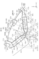
- FIG. 1 is a diagram showing an example of the basic shape of IPMSM.
- FIG. 2 is a view showing a rotor section of the IPMSM shown in FIG.
- FIG. 3 is a diagram showing an example of the optimum shape of the IPMSM.
- FIG. 4A is a diagram showing a first analysis result of magnetic flux density vectors in an optimally shaped IPMSM.
- FIG. 4B is a diagram illustrating an example of a schematic flow of magnetic flux in the first analysis result.
- FIG. 5A is a diagram showing a second analysis result of magnetic flux density vectors in an optimally shaped IPMSM.
- FIG. 5B is a diagram illustrating an example of a schematic flow of magnetic flux in the second analysis result.
- FIG. 1 is a diagram showing an example of the basic shape of IPMSM.
- FIG. 2 is a view showing a rotor section of the IPMSM shown in FIG.
- FIG. 3 is a diagram showing an example of the optimum shape of the IPM
- FIG. 6A is a diagram showing an example of a magnetic flux density vector in a basic shape IPMSM when the permanent magnet has a residual magnetic flux density of 0.4T.
- FIG. 6B is a diagram illustrating an example of a schematic flow of magnetic flux in a basic-shaped IPMSM when the residual magnetic flux density of the permanent magnet is 0.4T.
- FIG. 7A is a diagram showing an example of a magnetic flux density vector in a basic shape IPMSM when the permanent magnet has a residual magnetic flux density of 1.0 T.
- FIG. FIG. 7B is a diagram illustrating an example of a schematic flow of magnetic flux in a basic-shaped IPMSM when the permanent magnet has a residual magnetic flux density of 1.0T.
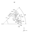
- FIG. 8 is a diagram illustrating an example of the configuration of the IPMSM according to the embodiment;
- FIG. 9 is a diagram showing an example of a rotor cross section of the embodiment.
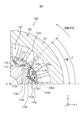
- FIG. 10 is a diagram showing an example of the configuration of the rotor core of the embodiment.
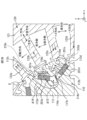
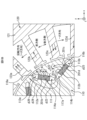
- 11A is an enlarged view of a portion of the rotor core shown in FIG. 10.
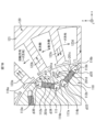
- FIG. 11B is a diagram showing a first modification of the configuration of the rotor core.
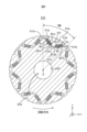
- FIG. 11C is a diagram showing a second modification of the configuration of the rotor core.
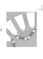
- FIG. 12A is a diagram showing a first example of the configuration of a rotor to be analyzed.
- FIG. 12B is a diagram showing a second example of the configuration of the rotor to be analyzed.
- FIG. 12A is a diagram showing a first example of the configuration of a rotor to be analyzed.
- FIG. 12B is a diagram showing a second example of the configuration of the
- FIG. 12C is a diagram illustrating a third example of the configuration of the rotor to be analyzed.
- FIG. 12D is a diagram showing a fourth example of the configuration of the rotor to be analyzed.
- FIG. 12E is a diagram showing a fifth example of the configuration of the rotor to be analyzed.
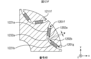
- FIG. 12F is a diagram showing a sixth example of the configuration of the rotor to be analyzed.
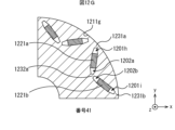
- FIG. 12G is a diagram showing a seventh example of the configuration of the rotor to be analyzed.
- FIG. 12H is a diagram showing an eighth example of the configuration of the rotor to be analyzed.
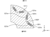
- FIG. 12I is a diagram showing a ninth example of the configuration of the rotor to be analyzed.
- the length, position, size, interval, and the like of the objects to be compared include not only being strictly the same but also being different without departing from the gist of the invention.
- the fact that the objects to be compared are the same includes that the objects to be compared are different within the range of tolerances determined at the time of design.
- the xyz coordinates indicate the orientation relationship in each figure.
- the symbol with a black circle ( ⁇ ) inside a white circle ( ⁇ ) is a symbol indicating an arrow line whose positive direction is the direction from the back side to the front side of the paper surface. .
- the inventors of the present invention have proposed a method of designing the shape of various cores including the IPMSM rotor core in Japanese Patent Application Laid-Open No. 2021-114099. Therefore, the present inventors used this method to search for a shape that contributes to an improvement in torque as the shape of the rotor core.
- Embodiments of the present invention, which will be described later, are made based on the results. The results will be described below, and the circumstances leading to the embodiments of the present invention, which will be described later, will be described.
- FIG. 1 illustrates a case where the IPMSM 100 has eight poles.
- the range of the double-headed arrow indicated as “1 pole” is the part that constitutes the 1 pole of the IPMSM 100 .
- the IPMSM 100 When the number of poles of the IPMSM 100 is n poles, the IPMSM 100 generally has an n-fold rotational symmetry relationship with the rotation axis 0 of the IPMSM 100 as the axis of rotational symmetry.
- IPMSM 100 includes rotor 110 and stator 120 .
- the stator 120 includes a stator core 121 and stator coils (not shown) to generate a rotating magnetic field.
- stator coils included in the stator 120 is omitted.
- a stator coil (not shown) is arranged in each slot 122 of the stator core 121 (as described above, only one slot is numbered in FIG. 1 for convenience of notation).
- the rotor 110 rotates around the rotational axis 0 of the IPMSM 100 .
- the rotor 110 includes a rotor core 111 and a plurality of permanent magnets per pole (two permanent magnets 112a-112b in the example shown in FIG. 1).
- Rotor core 111 is configured using a soft magnetic material.
- a case in which a plurality of permanent magnets 112 are installed in the rotor core 111 for each pole is illustrated. Therefore, a plurality of magnet holes per pole are formed in the rotor core 111 along the direction parallel to the rotation axis 0 of the rotor core 111 (in the following description, the direction parallel to the rotation axis 0 will be referred to as referred to as the z-axis direction).
- the magnet hole is a through hole penetrating in the z-axis direction.
- a plurality of permanent magnets 112a to 112b are installed (embedded) in rotor core 111 by being inserted into the magnet holes formed in rotor core 111, respectively. As described above, FIG.
- FIG. 1 shows the regions of the IPMSM 100 that form the two poles of the rotor 110 .
- two permanent magnets 112a-112b are embedded per pole. Therefore, a total of 16 permanent magnets are embedded in rotor core 111 .
- reference numerals for the sake of notation, only the portion forming one pole of the rotor 110 is denoted by reference numerals, and the reference numerals for the other portions forming the seven poles of the rotor 110 are omitted.
- the flux barriers 113a-113b, 114a-114b are regions through which magnetic flux does not pass, or regions through which magnetic flux is less likely to pass than regions around the flux barriers 113a-113b, 114a-114b.
- the case where there is no tangible material in the flux barriers 113a-113b and 114a-114b is illustrated that is, the case where the flux barriers 113a-113b and 114a-114b are voids (air regions) is illustrated).
- FIGS. 4A to 7B which will be described later, can be obtained.
- FIG. 2 is a diagram showing a cross section of the rotor for one pole of the IPMSM 100 shown in FIG.
- hatching indicating a cross section is omitted in order to avoid ambiguity of the positions indicated by the respective symbols.
- the direction perpendicular to the magnetic pole faces 201a-201b and 201c-201d is the magnetization direction Dm of the permanent magnets 112a-112b.
- the direction on both the left and right sides of the magnetization direction Dm of the permanent magnet 112 at the center of the permanent magnets 112a and 112b will be referred to as the left-right direction Ds as necessary.
- the left-right direction Ds is a direction perpendicular to the magnetization direction Dm of the permanent magnet 112 and the direction parallel to the rotation axis 0 of the IPMSM 100 .
- the flux barriers 113a-113b and 114a-114b are formed on both sides of the permanent magnets 112a-112b in the horizontal direction Ds.
- the flux barriers 113a to 113b and 114a to 114b the flux barriers positioned on the outer peripheral side of the permanent magnets 112a to 112b in the left-right direction Ds will be referred to as the outer peripheral flux barriers 113a to 113b as necessary. called.
- the flux barriers 113a to 113b and 114a to 114b the flux barriers located inside the permanent magnets 112a to 112b in the left-right direction Ds are referred to as inter-magnet flux barriers 114a to 114b as necessary.
- the bridge portions 116a and 116b are (narrow) regions that connect the soft magnetic material regions of the rotor core 111 in the circumferential direction.
- the circumferential direction is a direction around the outer peripheral surface 115 of the rotor 110 (rotor core 111) (a direction parallel and antiparallel to the rotation direction of the rotor 110 (rotor core 111)).
- the bridge portion 117 a is a (narrow) region that connects the soft magnetic material regions of the rotor core 111 in the radial direction of the IPMSM 100 .
- the bridge portions 116a to 116b and 117a the bridge portions 116a to 116b located on the outer peripheral side in the left-right direction Ds (the outer peripheral side in the radial direction of the IPMSM 100) relative to the permanent magnets 112a to 112b are is called an outer peripheral bridge portion.
- the bridge portion 117a located on the inner peripheral side in the left-right direction Ds (inner peripheral side in the radial direction of the IPMSM 100) relative to the permanent magnets 112a to 112b may be replaced by magnets as necessary. This is called an intermediate bridge portion 117a.
- the outer bridge portions 116 a - 116 b are regions of soft magnetic material located between the outer flux barriers 113 a - 113 b and the outer peripheral surface 115 of the rotor core 111 .
- the inter-magnet bridge portion 117a is a soft magnetic material region located between the inter-magnet flux barriers 114a and 114b.
- the bridge portions 116a-116b and 117a are for suppressing the return of the magnetic flux flowing out from the permanent magnets 112a-112b to the permanent magnet 112 concerned.
- the cross-sectional area perpendicular to the traveling direction of the magnetic flux is smaller than the other regions. Therefore, the magnetic resistance of the bridge portions 116 a to 116 b and 117 a is greater than that of other regions of the soft magnetic material forming the rotor core 111 . Therefore, by providing the bridge portions 116a to 116b and 117a, it is possible to prevent the magnetic flux flowing out from the permanent magnets 112a and 112b from returning to the permanent magnet 112 concerned.
- Bridge portions 116 a to 116 b and 117 a exist to ensure the mechanical strength of rotor core 111 . It is a common technical knowledge of those skilled in the art that the magnetic flux passing through the bridge portions 116a-116b and 117a circulates back to the permanent magnets 112a-112b and therefore hardly contributes to the torque of the rotor 110. FIG. In the following description, the magnetic flux that flows out from one magnetic pole face of the permanent magnet and returns (returns) to the other magnetic pole face of the permanent magnet through the bridge portion is referred to as return magnetic flux as necessary.
- the inventors designed the shape of the rotor core 111 by the method described in the specification of Japanese Patent Application Laid-Open No. 2021-114099.
- the flux barriers 113a to 113b and 114a to 114b shown in FIGS. 1 and 2 were set as design target elements (elements whose shape is changed from the basic shape).
- the permanent magnet 112 is used as a predetermined core element (an element whose shape is not changed) other than the element to be designed.
- the residual magnetic flux density of the permanent magnet 112 was set to 0.4T. Note that the residual magnetic flux density of the permanent magnet 112 is determined in advance according to the specifications of the permanent magnet 112, for example.
- a three-phase AC current having a peak value of 20 A and a frequency of 50 Hz was used as an exciting current flowing through a stator coil (not shown). Also, the advance angle was set to 30°.
- the optimization condition in the algorithm for the optimization problem is to maximize the average torque value of the rotor 110 while ignoring the stress generated in the rotor core 111 due to the centrifugal force that the rotor 110 receives as the rotor 110 rotates. That is, the shape shown in FIG. 3 is the optimum shape when the stress generated in rotor core 111 is allowed to become excessive. Therefore, the shape shown in FIG. 3 is a shape that does not consider whether the shape of the rotor core 111 can be realized as long as the optimization conditions are satisfied.
- FIG. 3 is a diagram showing an example of the configuration of the IPMSM 100, which is optimized to maximize the average torque value of the rotor 110 by the method described in the specification of Japanese Patent Application Laid-Open No. 2021-114099 from the IPMSM 100 of the basic shape. be.
- the IPMSM 100 shown in FIG. 3 will be referred to as the optimally shaped IPMSM 100 as appropriate. The knowledge obtained by the present inventors from the IPMSM 100 having the optimal shape shown in FIG. 3 will be described below.
- the optimum shape shown in FIG. 3 is a shape that allows the stress generated in the rotor core 111 to become excessively large.
- the outer bridge portions 116a to 116b are made of a soft magnetic material. Therefore, air has a smaller magnetic permeability than the outer bridge portions 116a and 116b, and air has a higher magnetic resistance than the outer bridge portions 116a and 116b. Therefore, in the IPMSM 100 having the optimum shape shown in FIG. 3, (parts of) the outer peripheral side flux barriers 113a to 113b shown in FIGS. Outer peripheral side flux barriers 113c to 113d are formed in such a manner.
- an open end is formed on the outer peripheral surface 115 of the rotor core 111 (soft magnetic material portion) by the outer peripheral side flux barriers 113c to 113d.
- the longitudinal direction of the open end is parallel to the z-axis direction, the short direction of the open end is the circumferential direction, and the open end communicates with the outside.
- the open end is an open end, and is a virtual surface rather than a real surface.
- the IPMSM 100 having the basic shape shown in FIG. 2 there are outer bridge portions 116a to 116b. Therefore, the outer flux barriers 113a and 113b do not reach the outer peripheral surface 115 and are closed. 2 and 3 are different in this point.
- the outer flux barriers 113c to 113d reach the outer peripheral surface 115 of the rotor core 111 and are open. From this, it can be said that most of the magnetic flux passing through the outer peripheral bridge portions 116a and 116b shown in FIGS. 1 and 2 is return magnetic flux.
- the return magnetic flux is reduced by the outer flux barriers 113c to 113d shown in FIG.
- the inventors found that the open ends 310c to 310d of the outer flux barriers 113c to 113d are displaced rearward in the rotational direction of the rotor core 111 (opposite to the rotational direction), as shown in FIG. I noticed that The inventors of the present invention considered that the outer flux barriers 113d to 113d played a role other than reducing the return magnetic flux, which is known as common technical knowledge.
- the inventors confirmed the results near the outer flux barriers 113c to 113d among the electromagnetic field analysis results (magnetic flux density vectors) of the IPMSM 100 having the optimum shape shown in FIG.
- r and .theta. respectively represent a radius vector and an angle of deviation in polar coordinates (circular coordinates).
- the position of the rotation axis 0 in the cross section of the rotor core 111 taken perpendicularly to the rotation axis 0 of the rotor core 111 is defined as the origin 0 of the polar coordinates.
- the outer side is the side where the outer peripheral surface 818 of the rotor core 811 exists.
- FIG. 4A and 4B are diagrams for explaining the first result of electromagnetic field analysis in the optimally shaped IPMSM 100.
- FIG. FIG. 4A is a diagram showing an example of a magnetic flux density vector in an optimally shaped IPMSM 100.
- FIG. 4B is a diagram illustrating an example of a schematic flow of magnetic flux in the vicinity of the outer peripheral surface 115 of the rotor core 111 among the magnetic fluxes in the IPMSM 100 having the optimal shape.
- the magnetic flux density vector is represented by an arrow line having a density corresponding to its magnitude.
- FIG. 4A the characteristics of the magnetic flux density vector cannot be clearly shown for convenience of notation. Therefore, for convenience of explanation, FIG.
- FIG. 4B shows an outline of the flow of magnetic flux necessary for explanation among the magnetic fluxes in the IPMSM 100 having the optimum shape.
- “N” and “S” shown in permanent magnets 112a-112b indicate the magnetic poles (north and south poles) of rotor 110.
- FIG. Therefore, the magnetic pole faces 201a and 201c of the permanent magnets 112a and 112b are N-pole magnetic pole faces, and the magnetic pole faces 201b and 201d are S-pole magnetic pole faces.
- the arrow lines shown in teeth 123a to 123d of stator core 121 indicate the time when rotor 110 and stator 120 have the positional relationship shown in FIGS. 4A and 4B.
- ⁇ 123d shows the magnetic flux generated.
- the arrow lines shown in the teeth 123a to 123b of the stator core 121 indicate that the magnetic flux is generated in the teeth 123a to 123b of the stator core 121 in the direction outward along the radial direction of the IPMSM 100 from the rotational axis 0 of the IPMSM 100.
- arrow lines shown in teeth 123c to 123d of stator core 121 indicate that magnetic flux is generated in teeth 123c to 123d of stator core 121 along the radial direction of IPMSM 100 in a direction toward rotation axis 0 of IPMSM 100.
- the number of arrow lines represents the relative magnitude relationship between the magnetic flux amounts (magnetic flux densities) in the teeth 123 c to 123 d of the stator core 121 . It should be noted that the larger the number of arrow lines, the larger the amount of magnetic flux (the higher the magnetic flux density). However, the ratio of the amount of magnetic flux (magnetic flux density) does not necessarily match the ratio of the number of arrow lines.
- the instantaneous value of the torque of the rotor 110 changes while the rotor 110 makes one rotation.
- the time when the positional relationship between rotor 110 and stator 120 is the positional relationship shown in FIGS. 4A and 4B is the time when the instantaneous value of the torque of rotor 110 is maximized.
- an arrow line extending from rotor 110 (rotor core 111) toward stator 120 (stator core 121) indicates the direction of magnetic flux flowing from rotor 110 (rotor core 111) toward stator 120 (stator core 121).
- An arrow line extending from stator 120 (stator core 121) toward rotor 110 (rotor core 111) indicates the direction of magnetic flux flowing from stator 120 (stator core 121) toward rotor 110 (rotor core 111).
- the magnetic fluxes ⁇ 1, ⁇ 2, and ⁇ 3 represented by these arrow lines are each represented by a single arrow line. However, the magnetic flux amounts of the magnetic fluxes ⁇ 1, ⁇ 2, and ⁇ 3 are not necessarily the same.
- the results shown in FIGS. 4A and 4B are the results when the rotor core 111 rotates counterclockwise toward the paper surface. Therefore, of the two permanent magnets 112a to 112b with the same pole, the permanent magnet 112a is positioned on the front side (rotational direction side) in the rotation direction, and the permanent magnet 112b is positioned on the rear side. (see the arrow lines beside "front side” and “back side” in Fig. 4B).
- the permanent magnet 112a located on the front side in the rotation direction is referred to as the front permanent magnet 112a as required.
- the permanent magnet 112b positioned on the rear side behind the rotation is referred to as the rear permanent magnet 112b as necessary.
- the outer flux barrier 113c Due to the outer flux barrier 113c, flux flows from one magnetic pole surface (for example, N pole) of the front permanent magnet 112a to the other magnetic pole surface (for example, S pole) via the outer peripheral bridge portion 116a shown in FIG. The return magnetic flux to be generated is reduced. Similarly, by the outer flux barrier 113b, one magnetic pole surface (for example, the N pole) of the rear permanent magnet 112b passes through the outer peripheral side bridge portion 116b shown in FIG. ) is reduced.
- the torque of the rotor 110 is the radial direction (the radial direction of the IPMSM 100) component B r and the circumferential component B Proportional to the inner product of ⁇ .
- the radial (radial direction of the IPMSM 100) component will be referred to as the radial component where appropriate. Therefore, when a polar coordinate system is defined as shown in FIG. 3, both the radial component B r and the circumferential component B ⁇ of the magnetic flux density vector in the direction from the rotor 110 toward the stator 120 are positive, and the magnetic flux density vector is a direction greatly inclined with respect to the radial direction of the IPMSM 100, the torque of the rotor 110 is increased.
- the magnetic flux ⁇ 1 directed from the region of the outer peripheral surface 115 of the rotor core 111 on the rear side in the rotation direction of the IPMSM 100 relative to the outer peripheral flux barrier 113c toward the teeth 123a of the stator core 121 is large in the radial direction of the IPMSM 100. leaning This is probably because the open end 310c of the outer flux barrier 113c is shifted rearward in the rotational direction of the rotor core 111 (opposite side in the rotational direction).
- the present inventors have found that the torque of the rotor 110 can be increased by shifting the open end 310 of the outer flux barrier 113 rearward in the rotational direction of the rotor core 111 (opposite side in the rotational direction). I got the first knowledge that I can do it.
- the magnetic flux ⁇ 1 directed to the teeth 123a of the stator core 121 from the region on the rear side in the rotation direction of the IPMSM 100 relative to the outer peripheral flux barrier 113c is The magnetic flux ⁇ 1 on the rear side of the flux barrier 113c is called.
- the magnetic flux opposite to the magnetic flux ⁇ 1 on the rear side of the outer peripheral flux barrier 113c also contributes to the increase in the torque of the rotor 110. As shown in FIG. This is because both the radial component B r and the circumferential component B ⁇ of the magnetic flux density vector are negative.
- the present inventors also noted that in the IPMSM 100 having the optimal shape shown in FIG. 3, the depressions 118a and 119a are formed at positions different from the outer flux barriers 113c to 113d. Therefore, the present inventors confirmed the results near the depressions 118a and 119a among the electromagnetic field analysis results (magnetic flux density vectors) in the optimally shaped IPMSM 100 shown in FIG.
- both the radial component B r and the circumferential component B ⁇ of the magnetic flux density vector directed from the stator 120 to the rotor 110 are negative, and the direction of the magnetic flux density vector is the IPMSM 100 , the torque of the rotor 110 is large.
- the result of the electromagnetic field analysis shown in FIG. 4A is the result when the exciting current flowing through the stator coil (not shown) is a three-phase alternating current. Therefore, IPMSM 100 generates a rotating magnetic field.
- the rotation period of rotor core 110 (rotor core 111) is the same as the rotation period of the rotating magnetic field generated in stator core 121 (teeth 123). Therefore, the positional relationship between rotor core 111 and the rotating magnetic field does not change even if rotor core 111 rotates.
- the excitation current used in the present application is not limited to the three-phase AC current.
- recess 118a faces teeth 123a and 123c with high magnetic flux density (teeth 123a and 123c with two arrow lines) even when rotor core 111 rotates.
- Magnetic flux ⁇ 2 directed from teeth 123c of stator core 121 to a region of outer peripheral surface 115 of rotor core 111 on the rear side in the rotational direction of IPMSM 100 relative to depression 118a is inclined with respect to the radial direction of IPMSM 100, and is inclined with respect to the radial direction of IPMSM 100.
- Both the radial component B r and the circumferential component B ⁇ of the magnetic flux density vector due to the magnetic flux ⁇ 2 are negative.
- the magnetic flux ⁇ 2 directed from the teeth 123c of the stator core 121 to the region of the outer peripheral surface 115 of the rotor core 111 that is on the rear side in the rotational direction of the IPMSM 100 relative to the recessed portion 118a contributes to an increase in the torque of the rotor 110.
- the magnetic flux ⁇ 2 directed from the teeth 123c of the stator core 121 to the region of the outer peripheral surface 115 of the rotor core 111 that is on the rear side of the recess 118a in the rotation direction of the IPMSM 100 is shifted to the region of the recess 118a as necessary.
- the magnetic flux ⁇ 2 on the rear side is called.
- the magnetic flux ⁇ 3 directed from the teeth 123c of the stator core 121 to the region of the outer peripheral surface 115 of the rotor core 111 that is forward of the recess 118a in the rotational direction of the IPMSM 100 is inclined with respect to the radial direction of the IPMSM 100, and , the radial component B r and the circumferential component B ⁇ of the magnetic flux density vector due to the magnetic flux ⁇ 3 are negative and positive, respectively.
- magnetic flux ⁇ 3 directed from teeth 123c of stator core 121 to a region of outer peripheral surface 115 of rotor core 111 that is forward of recessed portion 118a in the rotational direction of IPMSM 100 does not contribute to an increase in the torque of rotor 110.
- FIG. magnetic flux ⁇ 3 directed from teeth 123c of stator core 121 to a region of outer peripheral surface 115 of rotor core 111 that is on the front side in the rotational direction of IPMSM 100 relative to recessed portion 118a may be applied to recessed portion 118a as necessary.
- the magnetic flux ⁇ 3 on the front side is called.
- the torque of the rotor 110 can be increased by determining the size and position of the recessed portion 118a so that the magnetic flux ⁇ 2 on the rear side of the recessed portion 118a is greater than the magnetic flux ⁇ 3 on the front side of the recessed portion 118a.
- recessed portion 119a contributes less to the increase in the torque of rotor 110 than recessed portion 118a. Further, when the number of recessed portions increases, there is a possibility that the mechanical strength of the rotor 110 (rotor core 111) may decrease.
- the present inventors have found that by providing recessed portions 118a at positions facing teeth 123a and 123b having magnetic flux densities higher than the lowest magnetic flux density in the region of outer peripheral surface 115 of rotor core 111, rotor A second finding was obtained that the torque of 110 can be increased.
- the magnetic flux opposite to the magnetic flux ⁇ 2 on the rear side of the recess 118a also contributes to the increase in the torque of the rotor 110.
- FIG. This is because both the radial component B r and the circumferential component B ⁇ of the magnetic flux density vector are positive.
- the magnetic flux in the opposite direction to the magnetic flux ⁇ 3 on the front side of the recessed portion 118a does not contribute to the increase in the torque of the rotor 110 either.
- the radial component B r and the circumferential component B ⁇ of the magnetic flux density vector are negative and positive, respectively.
- the inter-magnet bridge portion 117 is made of a soft magnetic material. Therefore, air has a smaller magnetic permeability than the inter-magnet bridge portion 117 . Therefore, air has a larger magnetic resistance than the inter-magnet bridge portion 117 . Therefore, if all the inter-magnetic bridge portions including the inter-magnet bridge portion 117a shown in FIGS. will be replaced by This replacement reduces the permeability of the region. Therefore, the magnetoresistance of that region increases. Therefore, according to the above-mentioned common technical knowledge, it is considered that the return magnetic flux is reduced. From this, the inventors of the present invention expected that not only the outer bridge portions 116a and 116b shown in FIGS.
- the inter-magnet bridge portion 117a would serve as a flux barrier (gap portion).
- the optimally shaped IPMSM 100 shown in FIG. 3 produced results that differed from this expectation.
- the inter-magnet flux barriers 114a-114b shown in FIGS. 1 and 2 are not connected like the inter-magnet flux barriers 114c-114d. That is, in the optimally shaped IPMSM 100 shown in FIG. 3, a part of the inter-magnet bridge portion 117a shown in FIGS. 1 and 2 remains like the inter-magnet bridge portion 117b.
- the IPMSM 100 having the optimal shape shown in FIG. 3 has a shape different from the prediction described above.
- the outer peripheral side bridge portions 116a to 116b are closer to the stator 120 than the inter-magnet bridge portion 117a. Therefore, the magnetic flux passing through the outer peripheral bridge portions 116a and 116b is more likely to move toward the stator 120 than the magnetic flux passing through the inter-magnet bridge portion 117a. Therefore, it is considered that the magnetic flux passing through the peripheral bridge portions 116a and 116b is less likely to become a return magnetic flux than the magnetic flux passing through the inter-magnet bridge portion 117a.
- the magnetic flux directed toward the stator 120 can be increased by connecting the inter-magnet flux barriers 114a to 114b rather than by the outer peripheral flux barriers 113a to 113b reaching the outer peripheral surface 115 of the rotor core 111. It is conceivable that. However, as described above, the optimally shaped IPMSM 100 shown in FIG. 3 was shaped to show the opposite result.
- FIGS. 5A and 5B are diagrams illustrating the second results of electromagnetic field analysis in the optimally shaped IPMSM 100.
- FIG. 5A is a diagram showing an example of magnetic flux density vectors in the optimally shaped IPMSM 100, and is the same as FIG. 4A.
- FIG. 5B is a diagram illustrating an example of a schematic flow of magnetic flux near the permanent magnets 112a and 112b among the magnetic fluxes in the IPMSM 100 having the optimal shape.
- the notation method in FIG. 5B is the same as the notation method in FIG. 4B.
- FIG. 5B the directions of the magnetic flux flowing out of the permanent magnets 112a-112b are shown.
- the arrow lines extending from permanent magnets 112a-112b have the same meaning as the arrow lines shown inside teeth 123c-123d of stator core 121.
- the number of arrow lines extending from the permanent magnets 112a-112b represents the relative magnitude relationship of the amount of magnetic flux (magnetic flux density) flowing out from the permanent magnets 112a-112b.
- the length of the arrow lines extending from the permanent magnets 112a and 112b is irrelevant to the magnitude of the magnetic flux.
- the inter-magnet bridge portion 117b between the permanent magnets 112a and 112b is not replaced by the flux barrier). area), but toward the stator 120 (see magnetic flux ⁇ 11).
- the magnetic flux flowing out from the permanent magnet 112b on the rear side includes the magnetic flux that flows toward the stator 120 (see the magnetic flux ⁇ 12) and the magnetic flux that passes through the inter-magnet bridge portion between the permanent magnets 112a and 112b ( magnetic flux ⁇ 13, ⁇ 14).
- the magnetic flux that flows out from the rear permanent magnet 112b and passes through the bridge portion between the permanent magnets 112a and 112b does not return to the rear permanent magnet 112b, but rather ) or through a region on the inner peripheral side of the IPMSM 100 relative to the front permanent magnet 112a toward the stator 120 (see magnetic flux ⁇ 14).
- the present inventors divided the rotor core 111 by positively providing the inter-magnet bridge portion 117a and expanding the outer peripheral side flux barriers 113a to 113b to the outer peripheral surface 115 of the rotor core 111 to open it. A third finding was obtained that the torque of the IPMSM 100 can be increased without having to
- the cross section (xy cross section) of the rotor 110 in the direction perpendicular to the z-axis direction is the same at any position along the z-axis direction.
- the rotor core 111 may be skewed.
- the skew is realized by stacking a plurality of soft magnetic blocks in the z-axis direction while rotating them in the same direction by a predetermined angle about the z-axis.
- a permanent magnet is installed in each soft magnetic block. Therefore, for example, the number of permanent magnets required is the product of the number of magnet holes in each soft magnetic block and the number of soft magnetic blocks. Vibration of the rotary electric machine can be suppressed by applying such skew.
- the soft magnetic block is manufactured, for example, by stacking a plurality of soft magnetic plates having the same size and shape so that their contours (inner edge and outer edge) match.
- the shape and size of the soft magnetic plate used for each soft magnetic block may be the same or different.
- the outer edges of each soft magnetic block should be aligned.
- the predetermined angle may be the same or different for each soft magnetic block.
- the soft magnetic block may be constructed without using the plate-like soft magnetic material.
- FIG. 6A and 6B are diagrams showing an example of electromagnetic field analysis results for the IPMSM 100 in the basic shape when the residual magnetic flux density of the permanent magnets 112a and 112b is 0.4T.
- FIGS. 7A and 7B are diagrams showing an example of electromagnetic field analysis results for the IPMSM 100 in the basic shape when the residual magnetic flux density of the permanent magnets 112a and 112b is 1.0T. 4A to 7B, conditions other than the residual magnetic flux densities of permanent magnets 112a and 112b and the shape of rotor core 111 are the same.
- FIGS. 6A and 7A are diagrams showing examples of magnetic flux density vectors in the basic shape IPMSM 100 when the residual magnetic flux densities of the permanent magnets 112a to 112b are 0.4T and 1.0T, respectively.
- FIGS. 6B and 7B are diagrams for explaining an example of the outline of the magnetic flux flow in the basic shape IPMSM 100 when the residual magnetic flux densities of the permanent magnets 112a to 112b are 0.4T and 1.0T, respectively. Similar to FIGS. 4B and 5B, FIGS. 6B and 7B schematically show the flow of magnetic flux necessary for explanation among the magnetic fluxes in the basic IPMSM 100 for convenience of explanation. Note that the arrow lines in FIGS. 6B and 7B have the same meaning as the arrow lines in FIG. 5B.
- most of the magnetic flux passing through the inter-magnet bridge portion 117a is a magnetic flux that does not become a return magnetic flux like the magnetic flux ⁇ 13 to ⁇ 14 shown in FIG. 5B (magnetic flux ⁇ 13 to ⁇ 14 shown in FIG. See magnetic fluxes ⁇ 23 to ⁇ 24 shown in 6B).
- FIG. 7B when the residual magnetic flux density of the permanent magnets 112a and 112b is 1.0 T, most of the magnetic flux flowing out from the permanent magnets 112a and 112b and passing through the inter-magnet bridge portion 117a becomes return magnetic flux (magnetic flux ⁇ 33, ⁇ 34).
- the return flux was dominant in the magnetic flux passing through the inter-magnet bridge portion 117a. From this, it can be seen that when the residual magnetic flux density of the permanent magnets 112a to 112b is high, the magnetic fluxes ⁇ 13 to ⁇ 14 and ⁇ 23 to ⁇ 24 that do not become return magnetic fluxes shown in FIGS. 5B and 6B decrease.
- FIG. 7B when the residual magnetic flux density of the permanent magnets 112a to 112b is high, the magnetic fluxes ⁇ 13 to ⁇ 14 and ⁇ 23 to ⁇ 24 that do not become return magnetic fluxes shown in FIGS. 5B and 6B decrease.
- FIG. 7B as in FIG. 6B, there is a return magnetic flux that flows out from the permanent magnets 112a-112b and passes through the outer bridge portions 116a-116b (see magnetic fluxes ⁇ 35 and ⁇ 36). Also in FIG. 7B, as in FIG. 6B, there are magnetic fluxes directed from the permanent magnets 112a to 112b toward the stator 120 (see magnetic fluxes ⁇ 31 and ⁇ 32).
- the present inventors found that when permanent magnets 112a and 112b with low residual magnetic flux densities are used, the magnetic flux that contributes to the torque of the rotor 110 without becoming the return magnetic flux becomes the magnetic flux that passes through the inter-magnet bridge portion 117a.
- a fourth finding was obtained that a large amount was included. From this, if the conditions other than the residual magnetic flux density of the permanent magnets 112a-112b are the same, the permanent magnets 112a-112b with high residual magnetic flux density are used in the case of using the permanent magnets 112a-112b with low residual magnetic flux density. It is considered that the effect of improving the torque of the rotor 110 by providing the inter-magnet bridge portion 117a is greater than in the case of using it.
- the effect of improving the torque of the rotor 110 can be increased. Therefore, for example, it is possible to improve the torque of the rotor 110 without using a permanent magnet containing rare earth. For example, even if a ferrite magnet or the like is used as a permanent magnet that does not contain rare earth, the torque of rotor 110 can be improved.
- the embodiments of the present invention described below are made under the circumstances described above.
- FIG. 8 is a diagram showing an example of the configuration of the IPMSM 800. As shown in FIG. FIG. 8 is a cross-sectional view of IPMSM 800 taken perpendicular to IPMSM 800 (rotor 810) axis of rotation 0). As in FIG. 1, in FIG. 8, the range of the double-headed arrow indicated as "1 pole" is the part that constitutes one pole of the IPMSM800. In this embodiment, the case where the IPMSM 800 has eight poles is exemplified.
- IPMSM 800 includes rotor 810 and stator 120 .
- Stator 120 is the same as stator 120 shown in FIG. Therefore, here, the same reference numerals as those in FIG. 1 are assigned, and detailed description of the stator 120 is omitted.
- IPMSM 800 includes, for example, stator 120 (stator coil and stator core 121, not shown) defined as follows.
- the stator core 121 is composed of, for example, a yoke portion with a constant width and 24 tooth portions. The width of the yoke and the length of the teeth are the radial lengths of the IPMSM 800 .
- the shape of the yoke portion is, for example, an annular shape.
- the 24 teeth are arranged at equal intervals on the inner peripheral surface of the yoke.
- the width of the yoke portion is, for example, half the difference between the inner and outer diameters of stator 120 .
- the length of the tooth portion is, for example, 0.4 times the difference between the inner diameter and the outer diameter of stator 120 .
- Projections are formed at the tips of the teeth (ends on the rotation axis 0 side). The protrusions are formed to protrude to both sides in the circumferential direction.
- the circumferential length and width of the projection are, for example, 0.3 times the length of the teeth.
- the structure of the stator 120 is a structure that is generally adopted as a stator of IPMSM, the above knowledge does not change depending on the structure of the stator 120 .
- stator core 121 stator core 121 (teeth 123)
- a rotating magnetic field with a period corresponding to the frequency of the three-phase alternating current is generated.
- FIG. 8 as well as in FIG. 1, only the portion constituting one pole of the rotor 810 is denoted by reference numerals, and the reference numerals of the other portions constituting the seven poles of the rotor 810 are omitted.
- FIG. 9 is a diagram showing an example of the configuration (rotor cross section) of the rotor 810. As shown in FIG. In the following description, the direction of rotation of the rotor 810 is abbreviated as the direction of rotation as needed. As described above, in FIG. 9 as well as in FIG. 8, only the portion constituting one pole of the rotor 810 is denoted by reference numerals, and the reference numerals of the other portions constituting the seven poles of the rotor 810 are omitted.
- the rotor 810 includes a rotor core 811 and a plurality of permanent magnets 812a to 812b per pole.
- a rotor 810 includes a rotor core 811 and two permanent magnets 812a to 812b per pole.
- Rotor core 811 is configured using a soft magnetic material.
- the rotor core 811 is manufactured using, for example, a plurality of electromagnetic steel sheets laminated along the rotation axis 0 of the rotor 810 .
- rotor core 811 does not necessarily have to be manufactured using a plurality of laminated electromagnetic steel sheets.
- Rotor core 811 can be, for example, a dust core, an amorphous core, and a nanocrystalline core.
- the soft magnetic materials that make up the rotor core 811 are made of insulating-coated soft magnetic particles, an amorphous alloy, and a nanocrystalline alloy, respectively. be done.
- FIG. 10 is a diagram showing an example of the configuration of the rotor core 811.
- FIG. 10 is also a cross-sectional view of the rotor core 811 taken perpendicularly to the rotation axis 0 of the rotor core 811, as in FIGS.
- a cross section of the rotor core 811 taken perpendicularly to the rotational axis 0 of the rotor core 811 will be referred to as a rotor core cross section as necessary.
- the rotational axis 0 of the rotor core 811, the rotational axis 0 of the IPMSM 800, and the rotational axis 0 of the rotor 810 coincide. 10 as in FIGS. 8 and 9, only the portion forming one pole of the rotor core 811 is denoted by reference numerals, and the reference numerals of the other portions forming seven poles of the rotor core 811 are omitted. .
- a rotor core 811 is provided with a plurality of magnet holes 817a to 817b per pole.
- a case in which two magnet holes 817a to 817b are formed in the rotor core 811 for each pole will be exemplified.
- a case where the plurality of magnet holes 817a to 817b are through holes penetrating in the z-axis direction is exemplified.
- a plurality of permanent magnets 812a and 812b are installed (embedded) in rotor core 811 by being inserted into magnet holes 817a and 817b formed in rotor core 811, respectively.
- the rotor core 811 is provided with a plurality of magnet holes 817a-817b per pole as magnet holes in which the permanent magnets 812a-812b are installed. Therefore, in the example shown in FIG. 10, the magnet hole 817a is the front magnet hole in the rotation direction among the plurality of magnet holes installed at the same pole. In the example shown in FIG. 10, the magnet hole 817b is the rear magnet hole in the rotation direction of the rotor 810 (rotor core 811).
- the magnet hole 817a on the front side in the rotational direction of the rotor 810 (rotor core 811) will be referred to as the front magnet hole 817a as required.
- the magnet hole 817b on the rear side in the rotation direction of the rotor 810 (rotor core 811) will be referred to as the rear magnet hole 817b as necessary.
- the rotor core 811 is provided with holes 816 in which the permanent magnets 812a to 812b are not installed.
- a hole 816 is a through hole penetrating in the z-axis direction, and a shaft (not shown) or the like is installed. Holes other than hole 816 and magnet holes 817a to 817b may be formed in rotor core 811. FIG. These holes may or may not have permanent magnets 812a-812b installed.
- the direction orthogonal to the magnetic pole faces 901a-901d is the magnetization direction Dm of the permanent magnets 812a-812b.
- the magnetization direction Dm of the permanent magnets 812a-812b is the direction of the double arrow line shown across the permanent magnets 812a-812b.
- magnet holes 817a to 817b in which permanent magnets 812a to 812b are installed have magnetic pole faces 901a to 901d of permanent magnets 812a to 812b installed in magnet holes 817a to 817b. It is made to be tilted with respect to 818 .
- the permanent magnets 812a to 812b installed in the magnet holes 817a to 817b are spaced in the circumferential direction so that the closer they are to the outer peripheral surface 818 of the rotor core 811, the wider the magnets are.
- the case where holes 817a-817b are made is illustrated.
- the permanent magnets 812a to 812b are arranged in a so-called V shape.
- the residual magnetic flux density of the permanent magnets 812a and 812b is The lower one is preferable as long as the function as a magnet can be exhibited. It should be noted that functioning as a permanent magnet in the IPMSM 800 means that at least part of the magnetic flux generated by the permanent magnet reaches the stator 120 and becomes magnetic flux that contributes to the torque of the rotor.
- the residual magnetic flux density of the permanent magnets 812a-812b at room temperature exceeds 0.4 T, it may be necessary to use the permanent magnets 812a-812b containing rare earth. Also, if the residual magnetic flux density of the permanent magnets 812a-812b at room temperature exceeds 0.8 T, it may be necessary to use permanent magnets 812a-812b containing a large amount of rare earth.
- the residual magnetic flux density of the permanent magnets 812a and 812b at room temperature is preferably 0.8T or less, more preferably 0.4T or less. Further, it is preferable that the permanent magnets 812a and 812b contain less rare earth, and it is more preferable that the permanent magnets 812a and 812b contain no rare earth. However, the residual magnetic flux densities of the permanent magnets 812a and 812b at room temperature need not fall within the range described above as long as they can function as permanent magnets in the IPMSM.
- flux barriers 813a to 813b and 814a to 814b are spaces in which permanent magnets 812a to 812b do not exist among magnet holes 817a to 817b in which permanent magnets 812a to 812b shown in FIG. 10 are installed.
- the flux barriers 813a-813b, 814a-814b are voids (air regions).
- the flux barriers 813a-813b, 814a-814b are regions through which magnetic flux does not pass, or regions through which magnetic flux is less likely to pass than regions around the flux barriers 813a-813b, 814a-814b.
- the flux barriers 813a to 813b and 814a to 814b are exemplified by a case where no tangible object exists. However, this need not necessarily be the case. For example, among the magnet holes 817a-817b in which the permanent magnets 812a-812b shown in FIG. 814b may be configured.
- the flux barriers 813a to 813b located on the outer peripheral side in the left-right direction Ds from the permanent magnets 812a to 812b are outer peripheral side flux barriers.
- the outer peripheral flux barriers 813a to 813b reach and open to the outer peripheral surface 818 of the rotor 810 (rotor core 811) in the cross section of the rotor.
- the flux barriers 814a and 814b located on the inner peripheral side in the horizontal direction Ds of the permanent magnets 812a and 812b are flux barriers between magnets.
- the inter-magnet flux barriers 814a and 814b are not open except for the ends in the z-axis direction.
- the outer peripheral side refers to the outer peripheral surface 818 side of the rotor core 811
- the inner peripheral side refers to the inner peripheral surface 819 side of the rotor core 811 .
- the permanent magnet 812a is the front side permanent magnet 812a located on the front side of the permanent magnet 812b
- the permanent magnet 812b is the rear side permanent magnet 812b.
- the outer flux barrier 813a positioned on the outer peripheral side of the front permanent magnet 812a is positioned on the front side in the rotation direction of the front permanent magnet 812a.
- the outer flux barrier 813b located on the outer peripheral side of the rear permanent magnet 812b is located on the rear side in the rotation direction of the rear permanent magnet 812b.
- a recessed portion 815a is formed on the outer peripheral surface 818 of the rotor core 811.
- the recessed portion 815a is spaced from the teeth 123a, 123b different from the teeth 123b, 123d having the lowest magnetic flux density among the teeth 123 of the stator core 121, which are installed at positions facing the outer peripheral surface 818 of the rotor core 811 with a space therebetween. are made in opposing positions with As described in the section (History), the rotation period of rotor core 811 and the rotation period of the rotating magnetic field generated in stator core 121 (teeth 123) are the same.
- the magnetic flux density of the teeth 123 facing the recessed portion 815a remains the same.
- the number of recesses 815 per pole may be two or more.
- the magnetic flux density of the teeth 123a and 123c of the stator core 121, which are installed at positions facing the recessed portion 815a with a gap therebetween, is preferably high, and more preferably the highest magnetic flux density. This is because the torque of the rotor 810 can be increased.
- FIG. 11A is an enlarged view of a portion of rotor core 811 shown in FIG. 10 (a view showing a cross section of the rotor core).
- 11B and 11C are modifications to FIG. 11A.
- An example of the configuration of rotor core 811 of this embodiment will be described in detail with reference to FIGS. 10 and 11A to 11C.
- hatching indicating cross sections is omitted in order to avoid ambiguity of the positions indicated by the respective symbols.
- the soft magnetic material area (area other than hole 816 and magnet holes 817 a to 817 b ) is soft magnetic material portion 820 . As shown in FIGS.
- the magnet holes 817a-817b in which the permanent magnets 812a-812b are installed are divided into first ends 1111a-1111b, second ends 1112a-1112b, and third ends 1112a-1112b. It has ends 1113a-1113b and fourth ends 1114a-1114b.
- first ends 1111a-1111b, second ends 1112a-1112b, third ends 1113a-1113b, and fourth ends 1114a-1114b will be described below.
- the first ends 1111a and 1111b will be described.
- the first ends 1111a to 1111b are the ends located on the outermost side of the spaces that become the outer flux barriers 813a to 813b of the magnet holes 817a to 817b.
- the first ends 1111a to 1111b are open ends that are open at the position of the outer peripheral surface 818 of the rotor core 811 in the cross section of the rotor core.
- the first end portion 1111 may also be referred to as the open end portion 1011 in the following description.
- bent or curved portions in the cross section of the rotor core will be referred to as corner portions as necessary.
- the area of the outer peripheral surface 818 of the rotor core 811 that is different from the open end is not the corner portion.
- the position of the corner portion is assumed to be the bent position.
- the position of the corner portion is the position of the representative point of the curved portion (portion having curvature).
- the first end portions 1111a to 1111b are positioned at the outer peripheral surface 818 (the outermost side) of the rotor core 811 among the 12 corner portions of one magnet hole 817a to 817b in the cross section of the rotor core. It is a region along the circumferential direction from one to the other of two corner portions 1131a to 1131b and 1131c to 1131d. Note that the circumferential direction is the direction around the outer peripheral surface 818 of the rotor 810 (rotor core 811) (the direction parallel and antiparallel to the rotation direction of the rotor 810 (rotor core 811)).
- the circumferential length L1 of the first end portions 1111a-1111b is appropriately determined from such a point of view.
- the circumferential length L1 of the first end portions 1111a to 1111b is determined, for example, within a range of 0.1 to 1.0 times the length L2 of the magnetization direction Dm of the permanent magnets 812a to 812b. good.
- the permanent magnets 812a to 812b have a constant length in the magnetization direction Dm.
- the length in the magnetization direction Dm of the permanent magnets 812a-812b may not be constant.
- the representative value (for example, the average value) of the length L2 of the magnetization direction Dm of the permanent magnets 812a-812b is As the length, the length L1 in the circumferential direction of the first end portions 1111a to 1111b may be determined.
- the lengths of the other regions of the magnet holes 817a to 817b in the cross section of the rotor core are similar to the length L1 in the circumferential direction of the first end portions 1111a to 1111b. defined in terms of For example, the minimum length between the two opposing ends of the magnet holes 817a-817b in the cross section of the rotor core is, for example, 0.1 times or more the length of the magnetization direction Dm of the permanent magnets 812a-812b. It may be determined within the range of .0 times or less.
- the first ends 1111a and 1111b which are the open ends of the outer flux barriers 813a and 813b, are arranged behind the rotor core 811 in the rotational direction.
- the torque of the rotor 810 is increased by shifting to the side (opposite side of the rotation direction). In order to do so, in the present embodiment, as shown in FIG.
- the positions of the open end front side corner portions 1131a and 1131c of the first end portions 1111a and 1111b, which are the open ends, are aligned with the relevant
- the reference positions 831a and 831b with respect to the magnet holes 817a and 817b having the first ends 1111a and 1111b, which are open ends, are positioned rearward in the rotation direction of the rotor core 811.
- the open end front corner portions 1131a and 1131c of the first end portions 1111a and 1111b are the front corner portions in the rotation direction of the rotor core 811 among the corner portions of the first end portions 1111a and 1111b in the cross section of the rotor core. .
- the reference positions 831a and 831b with respect to the magnet holes 817a and 817b having the first ends 1111a and 1111b, which are open ends, are set at the magnet holes 817a and 817b in the cross section of the rotor core as shown in FIG. 11A. 1172 and 1174 passing through the permanent magnet reference ends 841a and 841b, which are one of the ends of the permanent magnets 812a and 812b, and the rotation axis 0, and the outer peripheral surface 818 of the rotor core 811.
- the permanent magnet reference ends 841a, 841b of the magnet holes 817a, 817b having the first ends 1111a, 1111b that are open ends are the ends of the permanent magnets 812a, 812b installed in the magnet holes 817a, 817b. , the end of one permanent magnet 812a or 812b that is closest to the respective open end (first end 1111a or 1111b).
- the permanent magnet reference ends 841a, 841b of the magnet holes 817a, 817b having first ends 1111a, 1111b that are open ends are the ends of the one permanent magnet 812a or 812b closest to the open ends.
- the position of the center in the circumferential direction of one pole (magnetic pole) region (the region surrounded by the broken line in FIG. 3) including the permanent magnet 812a or 812b and the rotation axis 0 (origin 0) is located at the furthest position in the circumferential direction from the straight line 1177 passing through .
- the distance in the circumferential direction from straight line 1177 is the distance determined on the side where the open end exists, out of the front side and the rear side in the rotational direction of rotor core 811 . As shown in FIG.
- the permanent magnet reference end 841a of the magnet hole 817a having the first end 1111a, which is an open end is located closer to the first end 1111a than the straight line 1177 among the ends of the permanent magnet 812a. on the front side where the distance in the circumferential direction from the straight line 1177 is the furthest.
- the permanent magnet reference end 841b of the magnet hole 817b having the first end 1111b, which is an open end is located on the rear side of the permanent magnet 812b, which is closer to the first end 1111b than the straight line 1177. , is the edge located furthest in the circumferential direction from the straight line 1177 .
- FIG. 11A a plurality of rotation axes 0 are shown for convenience of notation, but the actual rotation axis 0 is one as shown in FIGS. 8 to 10 (the rotation axis 0 shown in FIG. overlapping in one position).
- FIGS. 11B and 11C which will be described later.
- the magnet holes 817a and 817b are located on the front side and rear side of the straight line 1177 in the rotation direction of the rotor core 811, respectively. Therefore, the permanent magnet reference ends 841a and 841b are present only on one of the front side and the rear side of the straight line 1177 in the rotation direction of the rotor core 811, respectively.
- the magnet holes 817a to 817b are arranged so as to straddle the straight line 1177, and are formed on both sides in the left-right direction Ds of the permanent magnets 812a to 812b installed in the magnet holes 817a to 817b.
- both of the outer flux barriers 113 a - 113 b , 114 a - 114 b have open ends at the outer peripheral surface 818 of the rotor core 811 .
- the permanent magnet reference ends 841a and 841b are present on the front side and the rear side in the rotation direction of the rotor core 811 with respect to the straight line 1177 in the cross section of the rotor core.
- the position of the center of one pole region of the rotor in the circumferential direction is determined as the position of the midpoint of an imaginary straight line connecting the permanent magnet reference ends 841a and 841b, for example.
- a straight line 1177 is a straight line passing through this center position and the rotation axis 0 (origin 0).
- the open end front corner portions 1131a and 1131c are referred to as a front open end front corner portion and a rear open end front corner portion, respectively, as required. Further, in the following description, the open end 1111a of the front magnet hole 817a and the open end 1111b of the rear magnet hole 817b will be replaced with the front open end 1111a and the rear open end 1111b, respectively, as necessary. called.
- the front open end front corner portions 1131a are the two corners in the circumferential direction of the rotor core 811 of the front open end portion 1111a, which is the open end portion of the space 1123a that serves as the outer peripheral flux barrier of the front magnet hole 817a. Of the portions 1131a to 1131b, this is the corner portion 1131a on the forward side in the rotational direction of the rotor core 811. FIG.
- the rear open end front corner portions 1131c are the two corners in the circumferential direction of the rotor core 811 of the rear open end portion 111b, which is the open end portion of the space 1123b of the rear magnet hole 817b and serves as the outer peripheral flux barrier. Of the portions 1131c to 1131d, this is the corner portion 1131c on the front side in the rotation direction of the rotor core 811. FIG.
- the permanent magnet reference ends 841a to 841b have a front permanent magnet end 841a and a rear permanent magnet end 841b.
- the front permanent magnet end portion 841a is the end portion of the permanent magnets 812a to 812b installed in the front magnet hole 817a, which is located at the frontmost position in the rotational direction.
- the rear permanent magnet end 841b is the rearmost end in the rotational direction among the ends of the permanent magnet 812b installed in the rear magnet hole 817b.
- the reference positions 831a-831b have a front side reference position 831a.
- the reference positions 831 a to 831 b are the positions of intersections between the outer peripheral surface 818 of the rotor core 811 and a straight line 1172 passing through the front permanent magnet end 841 a and the rotation axis 0 .
- the reference positions 831a-831b have a rear side reference position 831b.
- the rear reference position 831 b is the position of the intersection of the outer peripheral surface 818 of the rotor core 811 and a straight line 1174 passing through the rear permanent magnet end 841 b and the rotation axis 0 .
- the open end front corner portions are configured as follows. is preferably positioned.
- N slots be the number of slots of stator core 121 installed at a position opposed to outer peripheral surface 818 of rotor core 811 with a gap therebetween.
- the reference position movement angle ⁇ a (rad) which is the angle around the rotation axis 0 from the reference positions 831a and 831b, is set to 2 ⁇ /N slot .
- the angle ⁇ f formed by the straight lines 1171 and 1172 is preferably between ⁇ a/24 and 15 ⁇ a/24, more preferably within the range of ⁇ a/3 ⁇ a/24.
- the straight line 1171 is a straight line that passes through the front open end front corner portion 1131a and the rotation axis 0 in the cross section of the rotor core.
- the front side open end corner portion 1131a is a corner portion located forward in the rotational direction from the center of the same pole in the circumferential direction among the open end front side corner portions 1131a and 1131c in the cross section of the rotor core. be.
- the straight line 1172 is a straight line passing through the rotation axis 0 and the reference position 831a with respect to the magnet hole 817a having the open end 1111a having the front open end front corner 1131a as one of the corners in the cross section of the rotor core. be.
- this angle .theta.f will be referred to as a forward outer peripheral flux barrier movement angle .theta.f as required.
- the angle ⁇ b formed by the straight lines 1173 and 1174 is preferably ⁇ a/24 or more and ⁇ a/8 or less, and more preferably within the range of ⁇ a/12 ⁇ a/24.
- a straight line 1173 is a straight line that passes through the rear open end front corner portion 1131c and the rotation axis 0 in the cross section of the rotor core.
- the rear open end front corner portion 1131c is a corner portion positioned rearward in the rotational direction from the circumferential center of the same pole among the open end front corner portions 1131a and 1131c.
- a straight line 1174 is a straight line that passes through a reference position 831b with respect to the magnet hole 817b having an open end portion 1111b with the rear side open end front side corner portion 1131c as one of the corner portions, and the rotation axis 0 in the cross section of the rotor core. be.
- this angle ⁇ b will be referred to as the movement angle ⁇ b of the rear outer peripheral flux barrier as required.
- the teeth 123a and 123b having a higher magnetic flux density than the lowest magnetic flux density in the region of the outer peripheral surface 818 of the rotor core 811 The torque of rotor 810 is increased by providing dimples 815a at opposing locations.
- the entire region of the recessed portion 815a faces the teeth 123a, 123b of the magnetic flux density.
- a partial region of the recessed portion 815a may face the teeth 123a and 123b having the magnetic flux density.
- the reference position movement angle ⁇ a (rad), which is the angle around the rotation axis 0 from the rear reference position 831b, is 2 ⁇ /N slots .
- the rear reference position 831b is the intersection of a straight line 1174 passing through the rear permanent magnet end 841b and the rotation axis 0 and the outer peripheral surface 818 of the rotor core 811 in the cross section of the rotor core.
- the rear permanent magnet end portion 841b is the end portion positioned furthest to the rear in the circumferential direction among the end portions of the permanent magnets 812a and 812b installed at the same pole.
- the straight line 1175 is a straight line that passes through the recess rear side corner portion 1161a and the rotation axis 0 in the cross section of the rotor core.
- the recess rearward corner portion 1161a is located on the rearward side in the rotational direction of the two corner portions 1161a to 1161b at the open end portion 1151a of the recess portion 815a in the cross section of the rotor core.
- a straight line 1173 is a straight line that passes through the rear open end front corner portion 1131c and the rotation axis 0 in the cross section of the rotor core.
- the rear open end front corner portion 1131c is positioned rearward in the rotational direction relative to the recessed portion 815a at the same pole as the pole where the recessed portion 815a is installed.
- the angle ⁇ c formed by the straight lines 1176 and 1175 is preferably ⁇ a/8 or more and 25 ⁇ a/24 ⁇ a or less, more preferably within the range of 3 ⁇ a/4 ⁇ a/12.
- a straight line 1176 is a straight line that passes through the recess front side corner portion 1161b and the rotation axis 0 in the cross section of the rotor core.
- the recess front corner portion 1161b is the front corner portion in the rotational direction of the two corner portions 1161a to 1161b at the open end portion 1151a of the recess portion 815a in the cross section of the rotor core.
- a straight line 1175 is a straight line that passes through the recess rear side corner portion 1161a and the rotation axis 0 in the cross section of the rotor core.
- this angle ⁇ c will be referred to as recess opening angle ⁇ c as required.
- the maximum value Cd of the depth of the recessed portion 815a is preferably within a range of 0.01 times or more and 0.1 or less times the diameter of the rotor core 811, and more preferably 0.04 times or more and 0.07 times the diameter of the rotor core 811. It is preferable to make it within the range of twice or less.
- the maximum depth Cd of the recess 815a will be referred to as the maximum depth Cd of the recess as required.
- the shape of the recessed portion 815a is not limited.
- the planar shape of the recessed portion 815a (the shape of the cross section of the rotor core) is a quadrangle having a line-symmetrical relationship with a straight line passing through the position of the center of gravity of the recessed portion 815a and the rotation axis 0 of the rotor core 811 as an axis of symmetry.
- the planar shape of the recessed portion 815a may be a shape that does not have symmetry.
- the planar shape of the recessed portion 815a may be a triangle or a polygon having a pentagon or more.
- the corner portion of the recessed portion 815a may have a curvature.
- the second ends 1112a and 1112b are ends located on the inner peripheral side in the left-right direction Ds of the magnet holes 817a-817b.
- the second ends 1112a-1112b coincide with and are closed to the ends of the intermagnet flux barriers 814a-814b. That is, the magnet holes 817a-817b serve as flux barriers extending along the rotational axis 0 between the permanent magnets 812a-812b and the second ends 1112a-1112b when the permanent magnets 812a-812b are installed. It has a shape that forms a space.
- the second ends 1112a-1112b extend from one of the two corners 1132a-1132b, 1132c-1132d of the magnet holes 817a-817b in which the permanent magnets 812a-812b are installed in the rotor core cross-section.
- the corners 1132a-1132b, 1132c-1132d forming the second ends 1112a-1112b are defined by the designer of the IPMSM 800 such that the magnet holes 817a-817b face each other with the inter-magnet bridge 821 therebetween. .
- FIG. 11A the second ends 1112a-1112b extend from one of the two corners 1132a-1132b, 1132c-1132d of the magnet holes 817a-817b in which the permanent magnets 812a-812b are installed in the rotor core cross-section.
- the second ends 1112a to 1112b of the two magnet holes 817a to 817b facing each other across the inter-magnet bridge portion 821 in the cross section of the rotor core are connected to each other. It contains the positions of the two ends of the shortest straight line.
- the region of the soft magnetic material where the stress is most concentrated when the rotor 810 (rotor core 811) is rotating is included between the second ends 1112a-1112b.
- the shortest straight line connecting the second ends 1112a and 1112b is the straight line 1141a connecting the corners 1132a and 1132c.
- the inter-magnet bridge portion 821a is, for example, a soft magnetic material surrounded by a straight line 1141a connecting two corner portions 1132a and 1132c and a straight line 1141b connecting two corner portions 1132b and 1132d. defined as the area of
- FIG. 11A illustrates a case where the entire area between the two magnet holes 817a and 817b is a soft magnetic material area. Therefore, the straight line 1141a connecting the second ends 1112a to 1112b of the two magnet holes 817a to 817b at the shortest distance overlaps the second ends 1112a to 1112b with the area of the soft magnetic material. It is the same as a straight line drawn so that the length is the shortest. On the other hand, this is not always the case when flux barriers are formed in the regions between the two magnet holes 817a and 817b. This is because the shortest straight line connecting the second ends 1112a to 1112b of the two magnet holes 817a to 817b may overlap the flux barrier.
- a region of soft magnetic material where the stress is most concentrated when the rotor 810 (rotor core 811) is rotating as described above is included between the second ends 1112a-1112b.
- the second ends include the positions of both ends of a straight line drawn between the second ends 1112a and 1112b so that the length of overlap with the region of the soft magnetic material is the shortest. In this way, regardless of whether there is a flux barrier in the region between each of the second ends 1112a-1112b, the soft core 810 (rotor core 811) experiences the greatest concentration of stress when it is rotating.
- a region of magnetic material may be included between the second ends 1112a-1112b.
- FIG. 11B is a diagram showing a first modification of the configuration of rotor core 811 (cross section of rotor core).
- a region of the soft magnetic material surrounded by a straight line 1141c connecting two corner portions 1132e and 1132h and a straight line 1141d connecting two corner portions 1132g and 1132j is a bridge between magnets. It is assumed that the area is defined as the area of the portion 821i.
- the second ends 1112c, 1112d extend from one to the other of the two corners 1132e and 1132g, 1132h and 1132j of the magnet holes 817c, 817d in which the permanent magnets 812a, 812b are installed. It becomes an area along the outline of 817d.
- FIG. 11B instead of the above, for example, a straight line 1141c connecting two corner portions 1132e and 1132h and a straight line 1141e connecting two corner portions 1132f and 1132i.
- the area may be defined as an area to be the inter-magnet bridge portion.
- the second ends 1112c, 1112d of the magnet hole 817 extend from one to the other of the two corners 1132e and 1132f, 1132h and 1132i of the magnet holes 817c, 817d where the permanent magnets 812a-812b are installed. It becomes an area along the contour.
- the second end 1112 also defines the contours of the magnet holes 817c, 817d from one to the other of the two corners 1132f and 1132g, 1132i and 1132j of the magnet holes 817c, 817d in which the permanent magnets 812a, 812b are installed. It may be a region along
- the positions of both ends of the straight line drawn so that the length overlapping the soft magnetic material constituting the soft magnetic body portion 820 is the shortest are the positions of the corner portions 1132f and 1132i.
- the second ends 1112c-1112d include the locations of the corners 1132f, 1132i.
- FIG. 11C is a diagram showing a second modification of the configuration of rotor core 811 (cross section of rotor core).
- FIG. 11C illustrates a case where the corner portions 1132a to 1132d of the second end portions 1112a to 1112b are changed to corner portions 1132k to 1132n having curvatures in comparison with FIG. 11A.
- the positions of the corner portions 1132k to 1132n shall be the positions of the representative points of the area having the curvature.
- the representative point of the corner portion is selected, for example, so that the size of the inter-magnet bridge portion is maximized.
- the positions of the black circles ( ⁇ ) indicating the corner portions 1132k to 1132n are the positions of the representative points of the corner portions 1132k to 1132n.
- the positions of the representative points of the corner portions 1132k to 1132n thus determined are treated as the positions of the corner portions 1132k to 1132n.
- the representative point of the corner portion does not necessarily have to be selected so that the size of the inter-magnet bridge portion is maximized.
- the central position of the area forming the corner may be selected as the representative point of the corner.
- the second ends 1112e, 1112f extend from one to the other of the two corners 1132k-1132l, 1132m-1132n of the magnet holes 817e, 817f in which the permanent magnets 812a, 812b are installed. It becomes an area along the contours of the magnet holes 817e and 817f.
- the representative point of the corner portion may be selected so that the size of the inter-magnet bridge portion is the smallest.
- the positions of both ends of the straight line drawn so that the length overlapping the soft magnetic material forming the soft magnetic body portion 820 is the shortest are the positions of both ends of the straight line 1141h. Therefore, the second ends 1112e to 1112f include the positions of both ends of the straight line 1141h.
- the position of the corner portion of the first end portion 1111 may be set as the representative point of the area having the curvature.
- the representative point of the corner portion of the first end portion 1111 is set, for example, at the position of the outer peripheral surface 818 of the rotor core 811 so that the size of the first end portion 1111 becomes the widest.
- the central position of the region having the curvature may be set as the representative point of the corner portion of the first end portion 1111 .
- the third ends 1113a and 1113b are ends located on the outer peripheral side in the magnetization direction Dm of the permanent magnets 812a-812b.
- the outer peripheral side in the magnetization direction Dm of the permanent magnets 812 a to 812 b is the side closer to the outer peripheral surface 818 of the rotor core 811 .
- the third ends 1113a, 1113b extend from the inner corners 1131b, 1131c of the two corners 1131a-1131b, 1131c-1131d that define the first ends 1111a, 1111b.
- the inner side is the side closer to the circumferential center position of one pole region of the rotor.
- the third ends 1113c, 1113d are, for example, magnet holes from corners 1131b, 1131c defining the first end 1111 to corners 1132e, 1132h defining the second end 1112.
- the third ends 1113e, 1113f extend from the corners 1131b, 1131c defining the first end 1111 to the corners 1132k, 1132m defining the second end 1112. This is the area along the contour of 817f.
- the fourth ends 1114a and 1114b are ends located on the inner peripheral side in the magnetization direction Dm of the permanent magnets 812a and 812b.
- the fourth ends 1114a, 1114b extend from the outer corners 1131a, 1131d of the two corners 1131a-1131b, 1131c-1131d that define the first ends 1111a, 1111b.
- the fourth ends 1114c, 1114d are, for example, from corners 1131a, 1131d defining the first end 1011 to corners 1132g, 1132j defining the second ends 1112c, 1112d.
- the fourth ends 1114e, 1114f extend from the corners 1131a, 1131d defining the first end 1111 to the corners 1132l, 1132n defining the second end 1112. This is the area along the contour of 817f.
- the two magnet holes 817a-817b, 817d-817e, 817f-817g in which the permanent magnets 812a-812b are installed have spaces 1121a-1121b in which the permanent magnets 812a-812b are installed.
- the two magnet holes 817a-817b, 817d-817e, and 817f-817g in which the permanent magnets 812a-812b are installed are divided into spaces 1121a-1121b in which the permanent magnets are installed and second ends 1112a-1112b and 1112c.
- the two magnet holes 817a-817b, 817d-817e, and 817f-817g in which the permanent magnets 812a-812b are installed are located between the spaces 1121a-1121b in which the permanent magnets are installed and the first ends 1111a-1111b.
- Spaces 1123a to 1123b, 1123c to 1123d, and 1123e to 1123f which become the outer flux barriers 813a to 813b shown in FIG. 8 are provided therebetween.
- spaces 1121a to 1121b in which permanent magnets 812a to 812b are installed spaces 1122a to 1122b, 1122c to 1122d, and 1122e to 1122f that serve as flux barriers between magnets, and spaces 1123a to 1123b and 1123c that serve as flux barriers on the outer peripheral side.
- ⁇ 1123d, 1123e ⁇ 1123f respectively, magnet installation spaces 1121a ⁇ 1122b, inter-magnet flux barrier spaces 1122a ⁇ 1122b, 1122c ⁇ 1122d, 1122e ⁇ 1122f, outer peripheral side flux barrier spaces 1123a ⁇ 1123b, 1123c ⁇ 1123d, 1123e to 1123f.
- Magnet installation spaces 1121a-1122b, flux barrier spaces between magnets 1122-1122b, 1122c-1122d, 1122e-1122f, and outer flux barrier spaces 1123a-1123b, 1123c-1123d, 1123e-1123f will be described.
- the outer peripheral flux barrier space 1123a is an example of a space that serves as the front flux barrier.
- the outer peripheral flux barrier space 1123b is an example of a space serving as a rear flux barrier.
- the inter-magnet flux barrier space 1122a is an example of a space serving as a rear flux barrier.
- the inter-magnet flux barrier space 1122b is an example of a space serving as the front flux barrier.
- the space serving as the front side flux barrier (the outer peripheral side flux barrier space 1123a, the inter-magnet flux barrier space 1122b) is different from the space serving as the rear side flux barrier (the inter-magnet flux The barrier space 1122a and the outer flux barrier space 1123b) are located forward in the rotational direction.
- the outer peripheral flux barrier space 1123a of the front magnet hole 817a is located forward in the rotational direction of the inter-magnet flux barrier space 1122a of the front magnet hole 817a, It is located on the outer peripheral side of the rotor core 811 from the inter-magnet flux barrier space 1122a of the 817a.
- the outer peripheral flux barrier space 1123b of the rear magnet hole 817b is located on the rear side in the rotational direction of the inter-magnet flux barrier space 1122b of the rear magnet hole 817b, and the magnet of the rear magnet hole 817b It is located on the outer peripheral side of the rotor core 811 from the interflux barrier space 1122b.
- the outer flux barrier space 1123a of the front magnet hole 817a and the outer flux barrier space 1123b of the rear magnet hole 817b have first ends 1111a to 1111b, which are open ends.
- both of the outer flux barrier spaces 1123a and 1123b preferably have open ends (first ends 1111a to 1111b).
- only one of the outer flux barrier spaces 1123a and 1123b may have an open end (first end 1111).
- the length L2 of the magnet installation spaces 1121a to 1121b in the width direction along the magnetization direction Dm of the permanent magnets 812a to 812b is the magnetization direction of the permanent magnets 812a to 812b. It is almost constant and equivalent to the length corresponding to the length of Dm. In order to facilitate installation of the permanent magnets 812a-812b in the magnet holes 817a-817b even if the length L2 in the width direction of the magnet installation spaces 1121a-1121b is the same as the length of the magnetization direction Dm of the permanent magnets 812a-812b.
- the permanent magnets 812a to 812b have a constant length in the magnetization direction Dm.
- the length of the magnetization direction Dm of the permanent magnets 812a-812b does not necessarily have to be constant. If the length of the magnetization direction Dm of the permanent magnets 812a-812b is not constant, the length of the magnet installation space 1121a-1121b in the width direction should be the length corresponding to the length of the magnetization direction Dm of the permanent magnets 812a-812b. You can make them equal. In this case, the lengths in the width direction of the magnet installation spaces 1121a and 1121b are not constant.
- the permanent magnets 812a-812b When the permanent magnets 812a-812b are installed, at least a partial region of the magnet installation spaces 1121a-1121b is occupied by the permanent magnets 812a-812b and ceases to be a space.
- the inter-magnet flux barrier spaces 1122a-1122b coincide with the inter-magnet flux barriers 814a-814b shown in FIG. 8 and remain empty even with the permanent magnets 812a-812b installed.
- the outer flux barrier spaces 1123a-1123b correspond to the outer flux barriers 813a-813b shown in FIG. 9 and remain empty even with the permanent magnets 812a-812b installed.
- the corner portions 1132e and 1132g are the two corner portions of the second end portion 1112c
- the corner portions 1132h and 1132j are the two corner portions of the second end portion 1112d. Illustrate.
- the soft magnetic body portion 820 has inter-magnet bridge portions 821a to 821h, outer portions 822a to 822h, and an inner portion 823a.
- the inter-magnet bridge portions 821a to 821h are regions in which the soft magnetic material exists among the bridge outer edge portions.
- the bridge outer edge is the outer corner of the second ends 1112a-1112b of the two magnet holes 817a-817b in which the permanent magnets 812a-812b are placed at the same pole.
- a straight line connecting 1132a and 1132c (see the chain double-dashed line connecting the outer ends of the second ends 1112a to 1112b in FIG. 10), and the second ends 1112a to 1112b of the two magnet holes 817a to 817b.
- FIG. 10 illustrates the case where only the soft magnetic material is present in the bridge outer edge portion 831a in this embodiment.
- the presence of only the soft magnetic material means that regions other than the soft magnetic material, such as flux barriers, are not included. Therefore, in this embodiment, the inter-magnet bridge portion 821a coincides with the bridge outer edge portion 831a.
- the bridge outer edge 831a corresponds to the area between the second ends 1112a-1112b of the two magnet holes 817a-817b in which the permanent magnets 812a-812b are placed at the same pole. do.
- the region between the second ends 1112a-1112b of the two magnet holes 817a-817b in which the permanent magnets 812a-812b are installed at the same pole includes a region other than the soft magnetic material such as a flux barrier.
- the magnet-to-magnet bridge portion 821a is an area obtained by removing the area other than the soft magnetic material from the bridge outer edge portion 831a.
- the number of inter-magnet bridge portions 821a to 821h is equal to the number of poles of rotor 810 (8 in this embodiment).
- the bridge outer edge portion 831a includes a straight line 1141a connecting corner portions 1132a and 1132c on the outer peripheral side of the second ends 1112a and 1112b of the magnet holes 817a and 817b, and the two magnets. Corner portions 1132d, 1132d on the inner peripheral side of the second ends 1112a to 1112b of the holes 817a to 817b are surrounded by a straight line 1141b connecting the second ends 1112a to 1112b of the two magnet holes 817a to 817b. It is an area where The inter-magnet bridge portion 821a coincides with the bridge outer edge portion 831a. This is the reason why the reference numerals 821a and 831a are shown side by side in FIGS. 10 and 11A.
- the bridge outer edge is defined as follows.
- the bridge outer edge portion 831b includes a straight line 1141c connecting the corner portions 1132e and 1132h on the outer peripheral side of the second ends 1112c to 1112d of the magnet holes 817a to 817b, and the two magnet holes 817a to 817b.
- the inter-magnet bridge portion 821i coincides with this bridge outer edge portion 831b. This is the reason why the reference numerals 821i and 831b are shown side by side in FIG. 11B.
- the bridge outer edge portion 831c is composed of a straight line 1141f connecting corner portions 1132k and 1132m on the outer peripheral side of the second ends 1112e to 1112f of the magnet holes 817a to 817b, and the two magnet holes 817a to 817b.
- a straight line 1141g connecting the corner portions 1132l and 1132n on the inner peripheral side of the second ends 1112e to 1112f of the magnet 817b and the second ends 1112e to 1112f of the two magnet holes 817a to 817b. be.
- the inter-magnet bridge portion 821j coincides with this bridge outer edge portion 831c. This is the reason why the symbols 821j and 831c are shown side by side in FIG. 11C.
- the outer portion 822a is a region in which the soft magnetic material is present in the outer edge portion.
- the outer edge portion is a region connected to the inter-magnet bridge portion 821 on the outer peripheral side of the inter-magnet bridge portion 821a.
- the outer perimeter comprises the third ends 1113a-1113b of the two magnet holes 817a-817b in which the permanent magnets 812a-812b are installed, the outer peripheral surface 818 of the rotor core 811, is the area surrounded by
- the present embodiment illustrates a case where only the soft magnetic material is present in the outer edge portion 832a (no region other than the soft magnetic material, such as a flux barrier, is included).
- the outer portion 822a coincides with the outer outer edge 832a.
- the outer edge portion 832a may include a region other than the soft magnetic material, such as a flux barrier.
- the outer portion 822a is an area obtained by removing the area other than the soft magnetic material from the outer edge portion 832a.
- the number of outer portions 822a-822h is equal to the number of poles of rotor 810 (8 in this embodiment).
- the outer edge portion 832a includes a straight line 1141a that connects corner portions 1132a and 1132c on the outer peripheral side of the second ends 1112a and 1112b of the magnet holes 817a and 817b, and a straight line 1141a that connects the two magnets. It is an area surrounded by the third ends 1113a to 1113b of the holes 817a to 817b and the outer peripheral surface 818 of the rotor core 811.
- FIG. The outer portion 822a coincides with this outer outer edge 832a. This is the reason why the reference numerals 822a and 832a are shown side by side in FIGS. 10 and 11A.
- the outer perimeter is defined as follows.
- the outer edge portion 832b includes a straight line 1141c connecting the corner portions 1132e and 1132h on the outer peripheral side of the second ends 1112c to 1112d of the magnet holes 817a to 817b, and the two magnet holes 817c to 817b. 817 d and the outer peripheral surface 818 of the rotor core 811 .
- the outer portion 822i coincides with this outer edge 832b. This is the reason why the symbols 822i and 832b are shown side by side in FIG. 11B.
- the outer edge portion 832c includes corner portions 1132k and 1132m on the outer peripheral side of the second ends 1112e to 1112f of the magnet holes 817a to 817b, and a straight line 1141f connecting the two magnet holes 817e to 1112m. It is a region surrounded by the third ends 1113e to 1113f of 817f and the outer peripheral surface 818 of the rotor core 811.
- FIG. The outer portion 822j coincides with this outer edge 832c. This is the reason why the symbols 822j and 832c are shown side by side in FIG. 11C.
- the inner part 823a is a region of the inner outer edge where the soft magnetic material is present.
- the inner outer edge portion is a region of a soft magnetic material connected to the inter-magnet bridge portion 821a on the inner peripheral side of the inter-magnet bridge portion 821a.
- the inner perimeter comprises the fourth ends 1114a-1114b of the two magnet holes 817a-817b in which the permanent magnets 812a-812b are installed, the outer peripheral surface 818 of the rotor core 811, This area is surrounded by the inner peripheral surface 819 of the rotor core 811 .
- FIG. 9 in this embodiment, the case where only the soft magnetic material is present in the inner outer edge portion 833a is illustrated.
- the inner portion 823a coincides with the inner outer edge portion 833a.
- the inner outer edge portion 833a may include a region other than the soft magnetic material, such as a flux barrier.
- the inner portion 823a is an area obtained by removing the area other than the soft magnetic material from the inner outer edge portion 833a.
- the number of inner portions 823a is one. Note that the inner portion 823 a does not necessarily need to be surrounded by the outer peripheral surface 818 of the rotor core 811 .
- the inner part 823a is the outer peripheral surface 818 of the rotor core 811. not surrounded by
- the inner outer edge portion 833a is a corner portion 1132b on the inner peripheral side of the second ends 1112a to 1112b of the two magnet holes 817a to 817b in which the permanent magnets 812a to 812b are installed, 1132d, the fourth ends 1114a-1114b of the two magnet holes 817a-817b, the outer peripheral surface 818 of the rotor core 811, and the inner peripheral surface 819 of the rotor core 811.
- the inner portion 823a coincides with this inner outer edge portion 833a. This is the reason why the reference numerals 823a and 833a are shown side by side in FIGS. 10 and 11A.
- the inner outer edge is defined as follows.
- the inner outer edge portion 833b is formed between corner portions 1132e and 1132h on the inner peripheral side of the second ends 1112c to 1112d of the two magnet holes 817c to 817d in which the permanent magnets 812a to 812b are installed. It is an area surrounded by a connecting straight line 1141c, the fourth ends 1114c to 1114d of the two magnet holes 817c to 817d, the outer peripheral surface 818 of the rotor core 811, and the inner peripheral surface 819 of the rotor core 811.
- the inner portion 823b coincides with this inner outer edge portion 833b. This is the reason why the symbols 823b and 833b are shown side by side in FIG. 11B.
- the inner outer edge portion 833c is formed between corner portions 1132l and 1132n on the inner peripheral side of the second ends 1112e to 1112f of the two magnet holes 817e to 817f in which the permanent magnets 812a to 812b are installed. It is an area surrounded by a connecting straight line 1141g, the fourth ends 1114e to 1114f of the two magnet holes 817e to 817f, the outer peripheral surface 818 of the rotor core 811, and the inner peripheral surface 819 of the rotor core 811.
- the inner portion 823c coincides with this inner outer edge portion 833c. This is the reason why the symbols 823c and 833c are shown side by side in FIG. 11C.
- the width w of the inter-magnet bridge portion 821a is represented by the length of the portion of the bridge width defining lines 1142a to 1142c overlapping the soft magnetic material in the cross section of the rotor core.
- the bridge width defining lines 1142a-1142c are the second ends 1112a of the two magnet holes 817a-817b, 817c-817d, 817e-817f in which the permanent magnets 812a-812b are installed.
- 1112b, 1112c to 1112d, and 1112e to 1112f are connected by straight lines so that the length of overlap with the soft magnetic material is the shortest.
- the second ends 1112a to 1112b of the two magnet holes 817a to 817b in which the permanent magnets 812a to 812b are installed are arranged so that the overlapping length of the soft magnetic material is the shortest.
- the connecting straight line is a straight line 1142a, which coincides with the above-described straight line 1141a. This is the reason why the symbols 1141a and 1142a are shown side by side in FIG. 11A.
- the width w of the inter-magnet bridge portion 821a is the length of the portion of the bridge width defining line 1142a overlapping the soft magnetic material in the cross section of the rotor core.
- the width w of the inter-magnet bridge portion 821a is equal to the length of the bridge width defining line 1142a.
- the width w of the bridge between magnets is the width of the portion of the bridge width defining line that overlaps the soft magnetic material. length. The length of the portion of the bridge width defining line overlapping the soft magnetic material is the length obtained by subtracting the length of the portion of the bridge width defining line not overlapping the soft magnetic material from the length of the bridge width defining line. .
- the straight line that connects the second ends 1112c to 1112d of the two magnet holes 817c to 817d in which the permanent magnets 812a to 812b are installed so as to minimize the overlapping length with the soft magnetic material is , a straight line 1142b, which coincides with the straight line 1141e described above.
- the bridge width defining line is the straight line 1142b.
- the width w of the inter-magnet bridge portion 821i is the length of the portion overlapping the soft magnetic material of the bridge width defining line 1142b in the cross section of the rotor core.
- all of the bridge width defining lines 1142b overlap with the soft magnetic material. Therefore, the width w of the inter-magnet bridge portion 821i is equal to the length of the bridge width defining line 1142b.
- the straight line that connects the second ends 1112e to 1112f of the two magnet holes 817e to 817f in which the permanent magnets 812a to 812b are installed so that the overlapping length of the soft magnetic material is the shortest is , a straight line 1142c, which coincides with the straight line 1141f described above.
- the bridge width defining line is the straight line 1142c.
- the width w of the inter-magnet bridge portion 821j is the length of the portion of the bridge width defining line 1142c overlapping the soft magnetic material in the cross section of the rotor core.
- all of the bridge width defining lines 1142c overlap with the soft magnetic material. Therefore, the width w of the inter-magnet bridge portion 821j is equal to the length of the bridge width defining line 1142c.
- the width w of the inter-magnet bridge portion 821 determined as described above is preferably 0.02 times or less the diameter of the rotor core 811 .
- the width w of the inter-magnet bridge portion 821 exceeds 0.02 times the diameter of the rotor core 811, the amount of magnetic flux passing through the inter-magnet bridge portion 821 increases, resulting in the return magnetic flux contained in the magnetic flux passing through the inter-magnet bridge portion 821. will increase. Therefore, the effect of increasing the torque of rotor 810 by magnetic fluxes (see magnetic fluxes ⁇ 13 and ⁇ 14 shown in FIG. 5B) that do not become return magnetic fluxes is reduced.
- the width w of the inter-magnet bridge portion 821 preferably exceeds the length w min determined by the following equation (1).
- wmin ⁇ S ⁇ rg ⁇ Ys (1)
- ⁇ is the density (kg/m 3 ) of the soft magnetic material forming the soft magnetic body portion 820 .
- ⁇ is predetermined according to the specifications of the IPMSM 800, for example.
- Ys is the yield stress (Pa) of the soft magnetic material forming the soft magnetic body portion 820 at room temperature.
- the yield stress (Ys) is predetermined according to the specifications of the soft magnetic material, for example.
- the yield stress (Ys) may be a measured value.
- the following may be done. First, a JIS No. 5 test piece is taken as a tensile test piece from the central portion of the soft magnetic material in the plate thickness direction. Then, the tensile test piece is subjected to a tensile test based on the description of JIS Z 2241:2011 to measure the yield stress (Ys). Under the present circumstances, let the rolling direction of a tensile test piece be a tensile direction.
- the yield stress (Ys) may be the upper yield point.
- the yield stress (Ys) may be the 0.2% yield strength measured by the offset method described in JIS Z 2241:2011.
- S is the area (m 2 ) in the cross section of the rotor core of an external force influence portion 824 (see 824a to 824c shown in FIGS. 11A to 11C), which will be described later.
- rg is the radial distance (m) from the center of rotation (rotational axis 0) of the rotor 810 (rotor core 811) to the position of the center of gravity G in the cross section of the rotor core of the external force affecting portion 824 (Figs. 11A to 11C See a straight line 1178 that connects the center of gravity G of the rotor core section of the external force influence portion 824 and the rotation axis 0).
- the position of the center of gravity G is defined as the point at which the resultant force of gravity acting on each portion of the external force influence portion 824 acts.
- 11A to 11C show approximate positions of the centers of gravity G of the external force influencing portions 824a to 824c for convenience of description and notation.
- ⁇ is the angular velocity (rad/sec) of the rotor 810 when rotating at maximum speed.
- the maximum rotation speed of the rotor 810 is the upper limit of the rotation speed of the rotor 810 that is allowed in the IPMSM 800 and is predetermined according to the specifications of the IPMSM 800 . If the width w of the inter-magnet bridge portion 821 is too large, the torque will decrease, so it is preferable to set the width w to 3.0 times or less of the length w min determined by the formula (1).
- the external force influence portion 824 is composed of the third ends 1113 of the two magnet holes 817a to 817b in which the permanent magnets 812a to 812b are installed at the same pole, and the outer peripheral surface of the rotor core 811 (soft magnetic body portion 820). 818 and the bridge width defining line 1142 .
- the external force affecting portion 824a includes the third ends 1113a-1113b of the two magnet holes 817a-817b in which the permanent magnets 812a-812b are installed, the outer peripheral surface 818 of the rotor core 811, and the bridge width This is the area of the soft magnetic material surrounded by the defining line 1142a.
- the external force affecting portion 824b includes the third ends 1113c to 1113d of the two magnet holes 817c to 817d in which the permanent magnets 812a to 812b are installed, the outer peripheral surface 818 of the rotor core 811, and the bridge width This is the area of the soft magnetic material surrounded by the defining line 1142b.
- the external force affecting portion 824c includes the third ends 1113e-1113f of the two magnet holes 817e-817f in which the permanent magnets 812a-812b are installed, the outer peripheral surface 818 of the rotor core 811, and the bridge width This is the area of the soft magnetic material surrounded by the defining line 1142c.
- the number of external force influence parts 824 included in one rotor 810 is equal to the number of poles of the rotor 810 (8 in this embodiment).
- S in the equation (1) is not the sum of the areas of the eight external force influence parts 824 in the rotor core cross section, but the area of one external force influence part 824 in the rotor core cross section.
- the area where the stress concentrates most when the rotor 810 (rotor core 811) is rotating is the soft magnetic material area overlapping the bridge width defining lines 1142a to 1142c. In the following description, this region will be referred to as a stress concentration region as required.
- the width w of the inter-magnet bridge portion 821 is equal to w min in equation (1)
- the stress generated in the stress concentration region when the rotor 810 (rotor core 811) is rotating at the maximum rotation speed is the yield of the soft magnetic material. (theoretically) equal to the stress. Therefore, in order to suppress breakage of the stress concentration region when the rotor 810 (rotor core 811) is rotating at the maximum rotation speed, the width w of the inter-magnet bridge portion 821 exceeds w min in formula (1). It is preferable to
- an IPMSM with two permanent magnets per pole arranged in a V shape is operated (rotated) according to electromagnetic field analysis conditions including excitation conditions.
- a magnetic flux density vector, an eddy current vector, and a torque in a minute area (mesh) were calculated by performing an electromagnetic field analysis using the finite element method.
- the torque was assumed to be Maxwell stress.
- stress analysis conditions including physical property values such as Young's modulus and Poisson's ratio
- Electromagnetic field analysis and stress analysis methods based on the finite element method are common methods, and detailed description thereof will be omitted here.
- the conditions other than the flux barrier and the recessed portion of the rotor core are the same including the electromagnetic field analysis conditions.
- the residual magnetic flux density of the permanent magnet was set to 0.4 T as a condition for the electromagnetic field analysis.
- the excitation current flowing through the stator coil was a three-phase AC current with a peak value of 20 A and a frequency of 50 Hz.
- the advance angle was set to 30°.
- the diameter of the rotor core is 27 mm.
- the stator core has 24 slots.
- the positions of the front corner portions 1131a and 1131c of the open end portion are located further than the reference positions 831a and 831b.
- Table 1 shows the result of verifying the effect of setting the rotation direction of 111 to the rear side.
- the ⁇ f column shows the movement angle ⁇ f (°) of the front outer peripheral flux barrier shown in FIG. 11A.
- the column of ⁇ b shows the movement angle ⁇ b (°) of the rear outer peripheral flux barrier shown in FIG. 11A.
- the reference position indicates that the moving angle ⁇ f of the front outer peripheral flux barrier and the moving angle ⁇ b of the rear outer peripheral flux barrier are 0°.
- the presence or absence of the recessed portion is shown in the column of the recessed portion.
- the moving angle ⁇ f of the front outer peripheral flux barrier and the moving angle ⁇ b of the rear outer peripheral flux barrier are angles formed by two straight lines (for example, straight lines 1171 and 1172). , take values greater than or equal to 0.
- a polar coordinate system is defined so that the positive direction of the deflection angle ⁇ is the same as the direction of rotation of the rotor.
- each of these movement angles ⁇ f and ⁇ b is a negative value, which means that the position is located on the negative direction side (rear side in the rotation direction) with respect to the reference position. The above is the same for the recess opening angle ⁇ c.
- 12A and 12B are diagrams showing the configurations (rotor cross sections) of the rotors to be analyzed in Nos. 9 and 19 of Table 1, respectively.
- 12C and 12D are diagrams showing the configurations (rotor cross sections) of the rotors to be analyzed in numbers 23 and 24 in Table 1, respectively.
- FIGS. 12A to 12D as in FIG. 1, one region of four regions obtained by dividing a cross section perpendicular to the rotation axis 0 of the IPMSM into four equal regions (regions constituting two poles of the rotor among IPMSM regions). indicates If the electromagnetic field analysis is performed only for this one region, the result of the electromagnetic field analysis for the entire rotor cross section can be obtained by utilizing the rotational symmetry of the IPMSM.
- FIGS. 12A to 12D like FIG. 1, only the parts constituting one pole of the rotor are denoted by reference numerals, and the reference numerals of the parts constituting the other poles of the rotor are omitted. do.
- the outer flux barriers 1201a to 1201e reach and open the outer peripheral surfaces 1211a to 1211d of the rotor core in the cross section of the rotor core. Further, the inter-magnet flux barriers 1202a and 1202b are not connected, and a soft magnetic material (inter-magnet bridge portion) exists between the inter-magnet flux barriers 1202a and 1202b.
- the movement angle ⁇ f of the front outer peripheral flux barrier is preferably ⁇ a/24 or more and 15 ⁇ a/24 or less, and preferably within the range of ⁇ a/3 ⁇ a/24. more preferred.
- the movement angle ⁇ f of the front outer peripheral flux barrier is preferably 0.625° or more and 9.375° or less, and more preferably within the range of 5 ⁇ 0.625°.
- the torque increase/decrease shows a positive value. I know it can be improved. Further, it can be seen that the torque of the rotor can be further improved in Nos. 8 to 10 where the moving angle ⁇ f of the front outer peripheral flux barrier is within the range of 5 ⁇ 0.625°. In particular, at No. 9 where the moving angle ⁇ f of the front outer peripheral flux barrier is 5°, which is the central value within the range of 5 ⁇ 0.625°, the torque increase/decrease value shows a maximum value. On the other hand, in No. 17 where the moving angle ⁇ f of the front outer peripheral flux barrier exceeds 9.375°, the torque increase/decrease shows a negative value, and it can be seen that the rotor torque cannot be improved.
- the movement angle ⁇ b of the outer peripheral flux barrier on the rear side is preferably ⁇ a/24 or more and ⁇ a/8 or less, and preferably within the range of ⁇ a/12 ⁇ a/24.
- the movement angle ⁇ b of the rear outer peripheral flux barrier is preferably 0.625° or more and 1.875° or less, preferably within the range of 1.25 ⁇ 0.625°. .
- both the movement angle ⁇ f of the outer flux barrier on the front side as shown in number 9 and the movement angle ⁇ b of the flux barrier on the rear side as shown in number 19 are defined in this embodiment.
- the torque increase/decrease value is larger than at numbers 2 to 16 and 18 to 20, and it can be seen that the rotor torque can be further improved.
- the recess opening angle ⁇ c is preferably ⁇ a/8 or more and 25 ⁇ a/24 ⁇ a or less, more preferably within the range of 3 ⁇ a/4 ⁇ a/12.
- the maximum depth Cd of the recessed portion is within a range of 0.01 times or more and 0.1 or less times the diameter of the rotor core. As described above, in this calculation example, the diameters of the rotor cores are all 27 mm.
- Number 24 shown in Table 1 is the same as number 27 in Table 2, which will be described later.
- the recess opening angle ⁇ c of the recess 1242a shown in FIG. 12D is 3.125°. Further, the maximum recess depth Cd of the recess 1242a shown in FIG. 12D is 0.05 times the diameter of the rotor core.
- No. 24 is the result of the same conditions as No. 23, except that the recessed portion 1242a was installed. Comparing Nos. 23 and 24, it can be seen that the torque of the rotor can be further improved by providing the recessed portion 1242a having the recessed portion opening angle ⁇ c and the maximum recessed portion depth value Cd within the ranges described in the present embodiment. I understand.
- the ⁇ c column and the Cd column respectively show the recess opening angle ⁇ c and the maximum recess depth value Cd shown in FIG. 11A.
- the rotor diameter*value is the value obtained by multiplying the value by the diameter of the rotor core.
- Other notations in Table 2 are the same as in Table 1.
- the number 23 shown in Table 1 is repeated.
- FIG. 12E is a diagram showing the configuration (rotor cross section) of the rotor subject to analysis in number 36 of Table 2.
- FIG. 12D is a diagram showing the configuration (rotor cross section) of the rotor to be analyzed in No. 27 of Table 2 (No. 24 of Table 1).
- No. 36 in Table 2 differs from No. 27 in Table 2 (No. 24 in Table 1) in recess opening angle ⁇ c of recesses 1242a to 1242b.
- the recess opening angle ⁇ c is preferably 1.975° or more and 15.625° or less, and more preferably within the range of 11.25° ⁇ 1.25°. . Further, it is preferable that the maximum depth Cd of the recessed portion is within a range of 0.01 times or more and 0.1 or less times the diameter of the rotor core.
- the torque of the rotor can be further improved in Nos. 29 to 30 where the recess opening angle ⁇ c is within the range of 11.25° ⁇ 1.25°.
- the recess opening angle ⁇ c is 11.25°, which is the central value within the range of 11.25° ⁇ 1.25°
- the increase/decrease value of the torque shows a maximum value.
- the torque of the rotor can be further improved in Nos. 35 to 37 where the maximum recess depth value Cd is in the range of 0.04 to 0.07 times the diameter of the rotor core.
- the value of torque increase/decrease shows a maximum value at number 36, where the maximum recess depth value Cd indicates a value near the center within a range of 0.04 to 0.07 times the diameter of the rotor core.
- any one of the movement angle ⁇ f of the outer peripheral flux barrier on the front side, the movement angle ⁇ b of the flux barrier on the rear side, the opening angle ⁇ c of the recess, and the maximum depth Cd of the recess It can be seen that if one is within the range described in this embodiment, the others need not be within the range described in this embodiment.
- the inter-magnet bridge portion 821 is positively provided, and the outer peripheral side flux barrier 813 is placed on the outer peripheral surface 818 of the rotor core 811.
- Table 3 shows the result of verifying the effect of enlarging and opening up to .
- 12F to 12I are diagrams showing configurations (rotor cross sections) of rotors to be analyzed in numbers 40 to 43 in Table 3.
- FIG. Here, in order to verify only the effect in the column ((third knowledge)), the moving angle ⁇ f of the front outer peripheral flux barrier and the moving angle ⁇ b of the rear flux barrier are set to Not within the scope described.
- the outer flux barriers 1201f to 1201g reach and open to the outer peripheral surface 1211f of the rotor core in the cross section of the rotor core.
- the inter-magnet flux barriers 1202a and 1202b are not connected, and a soft magnetic material (inter-magnet bridge portion 1232a) exists between the inter-magnet flux barriers 1202a and 1202b.
- the width w of the bridge between magnets is 0.3 mm.
- w min in equation (1) is 0.075 mm.
- the shape and size of the inter-magnet flux barriers 1202a-1202b shown in FIG. 12G are the same as the shape and size of the inter-magnet flux barriers 1202a-1202b of the rotor shown in FIG. 12F. Therefore, the shape and size of the inter-magnet bridge portion 1232a of the rotor shown in FIG. 12G are the same as the shape and size of the inter-magnet bridge portion 1232a of the rotor shown in FIG. 12F.
- the shape and size of the outer flux barriers 1201h to 1201i shown in FIG. 12G are the same as the shape and size of the inter-magnet flux barriers 1202a to 1202b. In FIG.
- the outer peripheral side flux barriers 1201h to 1201i and the inter-magnet flux barriers 1202a to 1202b are arranged so that the width of the outer peripheral side bridge portion and the width of the inter-magnet bridge portion are substantially uniform. Further, the outer flux barriers 1201h to 1201i shown in FIG. 12G do not reach the outer peripheral surface 1211g of the rotor core in the cross section of the rotor core and are not open.
- the width of the outer bridge portion is represented by the length in the cross section of the rotor core in the direction perpendicular to the direction in which the magnetic flux flows through the inter-magnet bridge portion.
- the width of the bridge portion between magnets is the shortest length among the lengths of the bridge portion between magnets (the length in the direction perpendicular to the direction in which the magnetic flux flows).
- a soft magnetic material exists between the permanent magnets 1221a-1221b (inter-magnet flux barriers 1202d-1202e).
- the shape and size of the outer peripheral flux barriers 1202d to 1202e shown in FIG. 12H are the same as the shape and size of the inter-magnet flux barrier 1232b.
- the outer peripheral side flux barriers 1201j to 1201k and the inter-magnet flux barriers 1202d to 1102e are arranged so that the width of the outer peripheral side bridge portions 1231c to 1231d and the width of the inter-magnet bridge portion 1232b are substantially uniform. .
- the width of the outer bridge portions 1231c to 1231d and the width of the inter-magnet bridge portion 1232b shown in FIG. 12H are respectively larger than the width of the outer peripheral-side bridge portions 1231a to 1231b and the width of the inter-magnet bridge portion 1132a shown in FIG. 12G. short.
- the width of the inter-magnet bridge portion is represented by the length of the portion where the bridge width defining line overlaps the soft magnetic material in the cross section of the rotor core.
- the bridge width defining line is a straight line that connects the second ends of the two magnet holes in which the permanent magnets are installed so that the length of overlap with the soft magnetic material is the shortest.
- the second end includes the positions of both ends of the straight line drawn so that the length overlapping the soft magnetic material constituting the soft magnetic body portion is the shortest distance. . Therefore, in the example shown in FIG. 12H, the length of the shortest straight line connecting the regions between the flux barriers 1202d to 1202e between magnets is the width of the bridge between magnetic poles.
- the outer flux barriers 1201j to 1201k shown in FIG. 12H do not reach the outer peripheral surface 1211h of the rotor core in the cross section of the rotor core and are not open.
- the inter-magnet flux barriers 1202d to 1202e shown in FIG. 12H are not connected. Therefore, a soft magnetic material (inter-magnet bridge portion) exists between the inter-magnet flux barriers 1202 (1202d to 1202e).
- the shape and size of the outer flux barriers 1201h to 1201i shown in FIG. 12I are the same as the shape and size of the outer flux barriers 1201h to 1201i of the rotor shown in FIG. 12G. Therefore, the shape and size of the outer bridge portions 1231a to 1231b shown in FIG. 12I are the same as the shape and size of the outer bridge portions 1231a to 1231b of the rotor shown in FIG. 12G.
- the number of flux barriers (flux barriers between magnets 1202f) on the inner peripheral side in the horizontal direction Ds of the permanent magnets 1221a to 1221b is one.
- the widths of the outer peripheral bridge portions 1131a to 1131b and the inter-magnet bridge portion 1132a are set to be the same as the width of the inter-magnetic bridge portion 1132a shown in FIG. 12F. It can be seen that when the width is wider than 1232b, the torque of the rotor becomes lower than when the width of the outer bridge portions 1231c to 1231d and the width of the inter-magnet bridge portion 1232b are narrowed as shown in FIG. 12H. Further, when the outer bridge portions 1231a to 1213b are provided as shown in FIG.
- the torque of the rotor is 12F is provided, and the width of the inter-magnet bridge portion 1232a is the same as that of the inter-magnetic pole bridge portion 1232a shown in FIG.
- the torque of the rotor is reduced by providing the outer peripheral bridge portions 1231c to 1231d and the inter-magnet bridge portion 1232b as shown in FIG. 1231d and the width of the inter-magnet bridge portion 1232b are smaller than the width of the outer peripheral side bridge portions 1231a-1231b and the width of the inter-magnet bridge portion 1232a shown in FIG. 12G.
- the torque of the rotor is provided, and as shown in FIG. It can be seen that the width becomes higher than when it is narrower than the width. That is, as shown in FIG. 12F, it can be seen that the rotor torque is highest when the inter-magnet bridge portion 1232a is provided and the outer flux barriers 1201f to 1201g are expanded and opened to the outer peripheral surface of the rotor core.
- Table 4 shows the calculation results of the stresses of the rotor shown in FIG. 12F and the rotor shown in FIG. 12H.
- the values shown in Table 4 are values calculated as follows. First, among the calculated values of the stress applied to the rotor core when it rotates at the number of rotations shown in the number of rotations column, the value of the maximum stress is calculated as the maximum stress applied to the rotor core when it rotates at that number of rotations. value. Then, the maximum value of the stress applied to the rotor core when rotating at the rotation speed is normalized by setting the maximum value of the stress applied to the rotor core of the rotor shown in FIG. (dimensionless). The values normalized in this manner are shown in each column of Table 4.
- the torque of the rotor shown in FIG. 12G and the torque of the rotor shown in FIG. 12I are smaller than the torque of the rotor shown in FIGS. 12F and 12H. Therefore, the rotors shown in FIGS. 12F and 12H are electromagnetically superior to the rotor shown in FIG. 12I. Therefore, Table 4 is used to compare the rotor shown in FIG. 12F and the rotor shown in FIG. 12H from a dynamic point of view.
- the width of the inter-magnet bridge portion 1232a shown in FIG. 12F is approximately the same as the sum of the widths of the outer peripheral side bridge portions 1231c to 1231d and the inter-magnet bridge portion 1232b shown in FIG. 12H.
- the rotor shown in FIG. 12F has a lower maximum stress applied to the rotor core than the rotor shown in FIG. 12H. Therefore, it can be seen that the rotor shown in FIG. 12F can improve resistance to centrifugal force more than the rotor shown in FIG. 12H. As described above, it can be said that the rotor (rotor core) shown in FIG. 12F has a shape that is mechanically and electromagnetically superior to the rotors (rotor cores) shown in FIGS. 12G to 12I.
- the open end front corner portions 1131a and 1131c are located on the rear side in the rotation direction of the rotor core 811 relative to the reference positions 831a to 831b in the cross section of the rotor core.
- the open end front side corner portions 1131a and 1131c are two corner portions 1131a to 1131b in the circumferential direction of the rotor core 811 of at least one open end portion 1111a to 1111b installed on the same pole in the rotor core cross section.
- 1131c to 1131d the front corner portion in the rotation direction of the rotor core 811.
- Reference positions 831a and 831b are reference positions for the magnet holes 817a and 817b having the open ends 1111a and 1111b, respectively. Therefore, the torque of rotor 810 can be increased.
- the position of the front open end front corner portion 1131a of the front open end 1111a is higher than the reference position 831a with respect to the magnet hole 817a having the front open end 1111a. It is on the rear side in the direction of rotation. Further, the position of the rear open end front corner portion 1131b of the rear open end portion 1111b is on the rear side in the rotational direction of the rotor core 811 relative to the reference position 831b with respect to the magnet hole 817b having the rear open end portion 1111b. It is in. Therefore, the torque of rotor 810, in which permanent magnets 812a-812b are arranged in a so-called V-shape, can be increased.
- the front outer peripheral flux barrier movement angle ⁇ f is set to ⁇ a/24 or more and 15 ⁇ a/24 or less ( ⁇ a is the reference position movement angle). Therefore, the torque of rotor 810 can be reliably increased.
- the movement angle ⁇ b of the rear outer peripheral flux barrier is set to ⁇ a/24 or more and ⁇ a/8 or less. Therefore, the torque of rotor 810 can be reliably increased.
- the length L1 of the open ends 1111a-1111b in the circumferential direction of the rotor core 811 is 0.1 to 1.0 times the length L2 of the magnetization direction Dm of the permanent magnets 812a-812b. Below. Therefore, return magnetic flux can be reliably suppressed.
- recessed portions 815a are provided at positions spacedly opposed to teeth 123a and 123b of stator core 121, which are placed at positions spacedly opposed to outer peripheral surface 818 of rotor core 811. As shown in FIG. The teeth 123a and 123b are different from the teeth 123b and 123d having the lowest magnetic flux density among the teeth 123a to 123d. Therefore, the torque of rotor 810 can be further increased.
- the recess opening angle ⁇ c is set to ⁇ a/8 or more and 25 ⁇ a/24 ⁇ a or less ( ⁇ a is the reference position movement angle). Therefore, the torque of rotor 810 can be reliably increased.
- the maximum depth Cd of the recessed portion is set within a range of 0.01 times or more and 0.1 or less times the diameter of the rotor core 811 . Therefore, the torque of rotor 810 can be reliably increased.
- the rotor core 811 has a plurality of magnetic pole holes per pole.
- the plurality of magnet holes per pole include first end portions 1111a to 1111b located on the outer peripheral side in the left-right direction Ds and first end portions 1111a to 1111b located on the inner peripheral side of the first end portions 1111a to 1111b in the left-right direction Ds. It includes two magnet holes 817a-817b each having two ends 1112a-1112b.
- the soft magnetic body portion 820 has an inter-magnet bridge portion 821a between the second ends 1112a-1112b of each of the two magnet holes 817a-817b.
- the second ends 1112a-1112b of the two magnet holes 817a-817b coincide with the ends of the inter-magnet flux barrier spaces 1122a-1122b and are closed.
- the first ends 1111a-1111b of the two magnet holes 817a-817b are open. Therefore, the torque of IPMSM 800 can be further increased.
- the width w of the inter-magnet bridge portion 821a is set to 0.02 times or less the diameter of the rotor core 811. Therefore, the width w of the inter-magnet bridge portion 821a can be further reduced. Therefore, the return magnetic flux contained in the magnetic flux passing through the inter-magnet bridge portion 821a can be further reduced. As a result, the magnetic flux that contributes to the torque of rotor 810 (the magnetic flux that does not become return flux) can be increased.
- the width w of the inter-magnet bridge portion 821a is set to exceed w min in the formula (1). Therefore, it is possible to suppress breakage originating from the inter-magnet bridge portion 821a due to the stress generated by the rotation of the rotor 810 (rotor core 811).
- the area between the second ends 1112a to 1112b of the two magnet holes 817a to 817b in which the permanent magnets 812a to 812b are installed at the same pole is made of the soft magnetic material. , so that there is no space that acts as a flux barrier. Therefore, if the size of the region between the second ends 1112a and 1112b is the same, the second end 1112a will be more dense than the case where the region between the second ends 1112a and 1112b has a region serving as a flux barrier. 1112b (bridge portion between magnets 821a) can be widened. Therefore, the size of the region between the second ends 1112a and 1112b can be minimized. Thereby, for example, the size of the area per pole of the rotor 810 (rotor core 811) can be narrowed.
- the residual magnetic flux density of the permanent magnets 812a to 812b at room temperature is set to 0.8 T or less. Therefore, the return magnetic flux contained in the magnetic flux passing through the inter-magnet bridge portion 821a can be further reduced. Therefore, the magnetic flux that contributes to the torque of rotor 810 (the magnetic flux that does not become return flux) can be increased. If the residual magnetic flux density of the permanent magnets 812a and 812b at room temperature is set to 0.4 T or less, the return magnetic flux contained in the magnetic flux passing through the inter-magnet bridge portion 821a can be further reduced. Therefore, the magnetic flux that contributes to the torque of rotor 810 (the magnetic flux that does not become return flux) can be increased.
- permanent magnets containing no rare earth are used as the permanent magnets 812a and 812b. Therefore, the torque of rotor 810 can be increased without using hard-to-obtain materials.
- the number of permanent magnets is 3 or more, it is preferable to do as follows. That is, it is necessary to determine the movement angle ⁇ f of the front-side outer peripheral flux barrier and the movement angle ⁇ b of the rear-side flux barrier. Of these, it is preferable that the permanent magnet is not installed in the region between the outer peripheral surface side end of the rotor core (the third end 1113 in the example shown in FIG. 11A) and the outer peripheral surface of the rotor core. By doing so, the rotor torque can be reliably improved by setting the moving angle ⁇ f of the front outer peripheral flux barrier and the moving angle ⁇ b of the rearward flux barrier within the ranges described in the present embodiment. be.
- the space serving as the flux barrier on both sides of the permanent magnet in the left-right direction Ds is the front flux barrier and the rear flux barrier. It becomes a flux barrier.
- both or one of the front and rear flux barriers have open ends.
- the IPMSM is exemplified as a permanent magnet-embedded rotating electric machine.
- the permanent magnet embedded rotating electric machine is not limited to the IPMSM.
- the permanent magnet embedded rotating electric machine may be IPMSG (Interior Permanent Magnet Synchronous Generator).
- a rotor core comprising a soft magnetic body portion formed using a soft magnetic material and having at least one magnet hole per pole, With respect to the permanent magnets installed in the magnet holes, the magnet holes are provided on both sides in the left-right direction perpendicular to the magnetization direction of the permanent magnets and the direction parallel to the rotation axis, which is the center of rotation, and front flux barriers.
- At least one space serving as a flux barrier out of the space serving as the front side flux barrier and the space serving as the rear side flux barrier has an open end that is open on the outer peripheral surface of the rotor core, In a cross-section perpendicular to the axis of rotation, the position of the open-end forward corner of at least one of the open-ends located at the same pole of the rotor is a reference to the magnet hole having the open-end.
- the front corner of the open end is one of the two corners in the circumferential direction of the rotor core of at least one of the open ends installed at the same pole of the rotor.
- the reference position for the magnet hole having the open end is one of the permanent magnets installed in the magnet hole that is closest to the open end.
- the permanent magnet reference end of the permanent magnet that is closest to the open end is one of the ends of the permanent magnet in the circumferential direction of one pole region that includes the permanent magnet.
- One pole including the permanent magnet located closest to the open end which is the end located furthest in the circumferential direction from a straight line passing through the central position and the rotation axis.
- the distance in the circumferential direction from a straight line passing through the position of the center of the region in the circumferential direction and the rotation axis is the side on which the open end is present, whichever of the front side and the rear side in the rotation direction of the rotor core.
- a rotor core which is the distance defined in [Disclosure 2] In the cross section, the positions of the open end front corners of all the open ends installed at the same pole of the rotor are higher than the reference position with respect to the magnet holes having the open ends of the rotor core.
- the rotor core according to Disclosure 1 on the rearward side in the direction of rotation.
- the rotor core has a plurality of magnetic pole holes per pole, the plurality of magnet holes have a front magnet hole positioned forward in the rotational direction and a rear magnet hole positioned rearward in the rotational direction;
- the space that the front magnet hole has and serves as the front flux barrier is located on the outer peripheral side of the space that the front magnet hole has and serves as the rear flux barrier, on the front side in the rotational direction and on the outer peripheral side of the rotor core.
- the space serving as the rear flux barrier provided by the rear magnet hole is located on the rear side in the rotational direction and on the outer peripheral side of the rotor core relative to the space serving as the front flux barrier provided by the rear magnet hole.
- the open end front corner has at least one of a front open end front corner and a rear open end front corner
- the front corner of the front open end is the front corner in the rotational direction of the two corners of the front open end in the circumferential direction of the rotor core
- the front-side open end is the open end of the space serving as the front-side flux barrier included in the front-side magnet hole
- the rear open end is the front corner in the rotational direction of the two corners of the rear open end in the circumferential direction of the rotor core
- the front corner portion of the rear side open end is the open end portion of the space serving as the rear side flux barrier included in the rear side magnet hole
- the permanent magnet reference end has at least one of
- the rotor core according to Disclosure 1 or 2 wherein in the cross section, the rear reference position is a position of an intersection of a straight line passing through the rear permanent magnet end and the rotation axis and an outer peripheral surface of the rotor core.
- the open end front corner portion has the front open end front corner portion and the rear open end front corner portion
- the permanent magnet reference end has the front permanent magnet end and the rear permanent magnet end
- the reference position has the front reference position and the rear reference position
- Disclosure 3 according to Disclosure 3 wherein each of the space serving as the front flux barrier included in the front magnet hole and the space serving as the rear flux barrier included in the rear magnet hole has the open end. rotor core.
- the open end front corner portion located on the front side in the rotational direction with respect to the circumferential center of the same pole passes through the rotation axis.
- the angle between a straight line and a straight line passing through the rotation axis and the reference position with respect to the magnet hole having the open end having the open end front corner as one of the corners is ⁇ a/24 or more. 15 ⁇ a/24 or less, ⁇ a is a movement angle (rad) that is an angle around the rotation axis from the reference position; ⁇ a is calculated by 2 ⁇ /N slots , 5.
- N slot is the number of slots of the stator core installed at a position facing the outer peripheral surface of the rotor core with a gap therebetween.
- N slot is the number of slots of the stator core installed at a position facing the outer peripheral surface of the rotor core with a gap therebetween.
- ⁇ a/8 or less ⁇ a is a movement angle (rad) that is an angle around the rotation axis from the reference position; ⁇ a is calculated by 2 ⁇ /N slots , 6.
- N slot is the number of slots of the stator core installed at a position facing the outer peripheral surface of the rotor core with a gap therebetween.
- the length of the open end in the circumferential direction is 0.1 to 1.0 times the length of the magnetization direction of the permanent magnet installed in the magnet hole having the open end.
- the soft magnetic body portion further has a recess portion having an open end that is open on the outer peripheral surface of the rotor core as a recess portion different from the space serving as the flux barrier,
- the recessed portion is located at a position opposed to a tooth different from the tooth having the lowest magnetic flux density among the teeth of the stator core installed at a position opposed to the outer peripheral surface of the rotor core with a space therebetween.
- a rotor core according to any one of Disclosures 1-7.
- the rotor core according to Disclosure 8 wherein N slot is the number of slots of the stator core installed at a position facing the outer peripheral surface of the rotor core with a gap therebetween.
- Disclosure 10 10.
- the rotor core has a plurality of magnetic pole holes per pole, the plurality of magnet holes have a front magnet hole positioned forward in the rotational direction and a rear magnet hole positioned rearward in the rotational direction;
- the space that serves as the front flux barrier, which the front magnet hole has, is located forward in the rotational direction of the space that serves as the rear flux barrier, which the front magnet hole has, and
- the space that serves as the front flux barrier, which the rear magnet hole has, is located on the rear side in the rotational direction of the space that serves as the rear flux barrier, which the rear magnet hole has, and
- the soft magnetic body portion is disposed between the magnets in a region between the space serving as the rear flux barrier included in the front magnet hole and the space serving as the rear flux barrier included in the rear magnet hole.
- the front magnet hole has a first end serving as the open end on the front side in the rotational direction with respect to the permanent magnet installed in the front magnet hole, the front magnet hole has a second end on the rear side in the rotational direction with respect to the permanent magnet installed in the front magnet hole;
- the rear magnet hole has a first end serving as the open end on the rear side in the rotational direction with respect to the permanent magnet installed in the rear magnet hole,
- the rear magnet hole has a second end forward in the rotational direction with respect to the permanent magnet installed in the rear magnet hole, 11.
- the length of the portion of the bridge width defining line overlapping the soft magnetic material is 0.02 times or less the diameter of the rotor core, 12.
- the bridge width defining line is a straight line that connects the second ends of the front magnet hole and the rear magnet hole so that a length of overlap with the soft magnetic material is the shortest. rotor core.
- each of the front magnet hole and the rear magnet hole is a third end located on the outer peripheral side in the magnetization direction of the permanent magnets installed in the front magnet hole and the rear magnet hole.
- the length of the portion of the bridge width defining line that overlaps with the soft magnetic material exceeds w min
- the bridge width defining line is a straight line that connects the second ends of the front magnet hole and the rear magnet hole so that the length of overlap with the soft magnetic material is the shortest
- w min is calculated by ⁇ ⁇ S ⁇ r g ⁇ ⁇ ⁇ Ys
- ⁇ is the density (kg/m 3 ) of the soft magnetic material
- Ys is the yield stress (Pa) of the soft magnetic material at room temperature
- S is the area (m 2 ) of the external force influence zone
- the external force influence portion includes the third end of the front magnet hole located at one end of the bridge width defining line and the rear magnet hole located at the other end of the bridge width defining line.
- r g is the distance (m) in the radial direction between the position of the center of gravity of the external force influence part in the cross section and the center of rotation; 13.
- ⁇ is the angular velocity (rad/sec) of the rotor when rotating at maximum speed.
- a rotor core comprising a soft magnetic body portion formed using a soft magnetic material and having at least one magnet hole per pole,
- the soft magnetic body part has a recessed part on the outer peripheral surface
- the magnet hole has a first end and a second end in a left-right direction perpendicular to the magnetization direction of the permanent magnet installed in the magnet hole and the direction parallel to the rotation axis that is the center of rotation, At least one end of the first end and the second end is an open end, the recess is at a different position than the open end;
- the recessed portion is located at a position opposed to a tooth different from the tooth having the lowest magnetic flux density among the teeth of the stator core installed at a position opposed to the outer peripheral surface of the rotor core with a space therebetween.
- rotor core In the cross section, of the two corners at the open end of the recess, a straight line passing through a rear corner of the recess, which is a rear corner in the rotational direction of the rotor core, and the rotation axis, and the recess The angle formed by a straight line passing through the rotation axis and the front corner of the open end portion located on the rear side in the rotation direction of the recessed portion at the same pole as the pole where the portion is installed is ⁇ a.
- the front corner of the open end is one of the two corners in the circumferential direction of the rotor core of at least one of the open ends installed at the same pole of the rotor.
- ⁇ a is the front corner of the a straight line passing through the front corner portion of the recess portion, which is the front corner portion in the rotational direction, and the rotation axis, and the rear corner portion of the recess portion;
- the angle formed by the straight line passing through the rotation axis is ⁇ a/8 or more and 25 ⁇ a/24 ⁇ a or less, ⁇ a is an angle about the rotation axis from a rear reference position, which is the intersection of a straight line passing through the rear permanent magnet end portion and the rotation axis, and the outer peripheral surface of the rotor core in the cross section.
- the rotor core according to Disclosure 14 wherein N slot is the number of slots of the stator core installed at a position facing the outer peripheral surface of the rotor core with a gap therebetween. [Disclosure 16] 16. The rotor core according to disclosure 14 or 15, wherein the maximum depth of the recessed portion is in the range of 0.01 times or more and 0.1 times or less of the diameter of the rotor core.
- the present invention can be used, for example, in rotating electric machines.
Landscapes
- Engineering & Computer Science (AREA)
- Power Engineering (AREA)
- Permanent Field Magnets Of Synchronous Machinery (AREA)
- Iron Core Of Rotating Electric Machines (AREA)
Abstract
Description
本発明のロータは、前記ロータコアと、前記ロータコアに設置される複数の永久磁石と、を備える。
本発明の回転電機は、前記ロータと、前記ステータと、を備える。
なお、長さ、位置、大きさ、間隔等、比較対象が同じであることは、比較対象が厳密に同じであることの他、発明の主旨を逸脱しない範囲で比較対象が異なることも含む。例えば、比較対象が同じであることには、比較対象が設計時に定められる公差の範囲内で異なることも含む。また、各図において、x-y-z座標は、各図における向きの関係を示すものである。x-y-z座標において、白丸(〇)の中に黒丸(●)が付されている記号は、紙面の奥側から手前側に向かう方向が正の方向である矢印線を示す記号である。また、各図において、表記の都合上、同一の構成要素が複数ある場合、当該複数の構成要素のうちの一部の構成要素の符号の図示を省略する。また、以下では、当該複数の構成要素の説明を、必要に応じて、当該複数の構成要素のうち符号を付した構成要素を用いて行う。
本発明者らは、特開2021-114099号公報において、IPMSMのロータコアを始めとする各種のコアの形状を設計する手法を提案した。そこで、本発明者らは、当該手法を用いて、ロータコアの形状としてトルクの向上に寄与する形状を探索した。後述する本発明の実施形態は、その結果に基づいてなされたものである。以下に、その結果について説明し、後述する本発明の実施形態に至った経緯を説明する。
ステータ120は、ステータコア121と、不図示のステータコイルと、を備え、回転磁界を発生させるためのものである。なお、図1では、ステータ120が備えるステータコイルの図示を省略する。しかしながら、不図示のステータコイルは、ステータコア121の各スロット122に配置される(前述したように、表記の都合上、図1では一つのスロットのみに符号を付している)。
ロータ110は、ロータコア111と、1極当たり複数の永久磁石(図1に示す例では2個の永久磁石112a~112b)と、を備える。ロータコア111は、軟磁性材料を用いて構成される。
前述したように、図3に示す最適形状は、ロータコア111に生じる応力が過大になることを許容する場合の形状である。外周側ブリッジ部116a~116bは軟磁性材料で構成される。したがって、外周側ブリッジ部116a~116bよりも空気の方が透磁率は小さいため、外周側ブリッジ部116a~116bよりも空気の方が磁気抵抗は大きい。よって、図3に示す最適形状のIPMSM100では、図1および図2に示した外周側フラックスバリア113a~113b(の一部)は、ロータコア111の外周面115に到達して外部に開放(連通)するように、外周側フラックスバリア113c~113dが形成される。換言すれば、ロータコア111(軟磁性体部)の外周面115には、外周側フラックスバリア113c~113dによって開放端部が形成される。当該開放端部の長手方向は、z軸方向に平行な方向であり、当該開放端部の短手方向は、周方向であり、当該開放端部は、外部に連通する。なお、開放端部は、開放されている端部であり、実在する面ではなく仮想面である。図2に示す基本形状のIPMSM100では、外周側ブリッジ部116a~116bが存在する。したがって、外周側フラックスバリア113a~113bは外周面115に到達しておらず、閉じている。この点で、図2と図3とは異なる。一方、図3に示す最適形状のIPMSM100において、外周側フラックスバリア113c~113dはロータコア111の外周面115に到達して開放している。このことから、図1および図2に示す外周側ブリッジ部116a~116bを通過する磁束の多くは還流磁束であると言える。
また、本発明者らは、図3に示す最適形状のIPMSM100において、外周側フラックスバリア113c~113dとは別の位置に窪み部118a、119aが形成されていることに着目した。そこで、本発明者らは、図3に示す最適形状のIPMSM100における電磁界解析の結果(磁束密度ベクトル)のうち、窪み部118a、119a付近の結果を確認した。
図1および図2において、磁石間ブリッジ部117は軟磁性材料で構成される。したがって、磁石間ブリッジ部117よりも空気の方が透磁率は小さい。したがって、磁石間ブリッジ部117よりも空気の方が磁気抵抗は大きい。よって、図1および図2に示した磁石間ブリッジ部117aを含むの全ての磁極間ブリッジ部がフラックスバリア(空隙部)であれば、磁石間ブリッジ部を構成する磁性体材料の領域が空隙部に置き換わることになる。この置き換わりにより、当該領域の透磁率は小さくなる。したがって、当該領域の磁気抵抗は増大する。よって、前述した技術常識によれば、還流磁束が低減されると考えられる。このことから、本発明者らは、図1および図2に示す外周側ブリッジ部116a~116bのみならず磁石間ブリッジ部117aもフラックスバリア(空隙部)になると予想した。しかしながら、図3に示す最適形状のIPMSM100では、この予想とは異なる結果となった。しかしながら、図3に示す最適形状のIPMSM100では、磁石間フラックスバリア114c~114dのように、図1および図2に示した磁石間フラックスバリア114a~114bは繋がらない。すなわち、図3に示す最適形状のIPMSM100では、磁石間ブリッジ部117bのように、図1および図2に示した磁石間ブリッジ部117aの一部が残っている。このように図3に示す最適形状のIPMSM100は、前述した予想とは異なる形状となった。
図5A~図5Bは、最適形状のIPMSM100における電磁界解析の第2の結果を説明する図である。図5Aは、最適形状のIPMSM100における磁束密度ベクトルの一例を示す図であり、図4Aと同じである。図5Bは、最適形状のIPMSM100おける磁束のうち、永久磁石112a~112b付近の磁束の流れの概略の一例を説明する図である。
さらに、本発明者らは、永久磁石112a~112bの残留磁束密度が低いと、永久磁石112a~112bで発生する磁束量が小さくなる(磁束密度が低くなる)ため、磁束が還流しづらくなると考えた。そこで、図1に示した基本形状のIPMSM100に対して永久磁石112a~112bの残留磁束密度を0.4T、1.0Tとした場合のそれぞれにおける電磁界解析を実行した。図6A~図6Bは、永久磁石112a~112bの残留磁束密度が0.4Tである場合の基本形状のIPMSM100における電磁界解析の結果の一例を示す図である。図7A~図7Bは、永久磁石112a~112bの残留磁束密度が1.0Tである場合の基本形状のIPMSM100における電磁界解析の結果の一例を示す図である。なお、図4A~図7Bにおいて、永久磁石112a~112bの残留磁束密度およびロータコア111の形状以外の条件は同じである。
以下に説明する本発明の実施形態は、以上の経緯でなされたものである。
以下、本発明の一実施形態を説明する。本実施形態では、回転電機がインナーロータ型のIPMSMである場合を例示する。図8は、IPMSM800の構成の一例を示す図である。図8は、IPMSM800(ロータ810)の回転軸線0)に対して垂直に切った場合のIPMSM800の断面図である。図1と同様に、図8において、「1極」と示している両矢印線の範囲がIPMSM800の1極を構成する部分である。本実施形態では、IPMSM800が8極である場合を例示する。しかしながら、IPMSM800の極数は8極に限定されない。前述したようにIPMSM800の極数がn極である場合、IPMSM800は、概ね、IPMSM800の回転軸線0を回転対称軸とするn回対称の回転対称性の関係を有する。nは2以上の整数であり、図8に示す例ではnは8である(n=8)。
図10において、ロータコア811が占める領域のうち、軟磁性材料の領域(穴816、磁石穴817a~817b以外の領域)が軟磁性体部820である。図10および図11Aに示すように、ロータコア断面において、永久磁石812a~812bが設置される磁石穴817a~817bは、第1端部1111a~1111bと、第2端部1112a~1112bと、第3端部1113a~1113bと、第4端部1114a~1114bと、を有する。以下に、第1端部1111a~1111bと、第2端部1112a~1112bと、第3端部1113a~1113bと、第4端部1114a~1114bの一例を説明する。
ロータコア811の外周面818と間隔を有して対向する位置に設置されるステータコア121のスロット数(個)をNslotとする。また、基準位置831a~831bからの回転軸線0周りの角度である基準位置移動角度θa(rad)を2π/Nslotとする。図8に示す例では、ステータコア121のスロット数(個)をNslotは24個であるので、基準位置移動角度θaは、2π/24(rad)=15(°)である。
図11Bに示す例において、例えば、2個のコーナ部1132e、1132hを結ぶ直線1141cと、2個のコーナ部1132g、1132jを結ぶ直線1141dと、により囲まれる軟磁性材料の領域が、磁石間ブリッジ部821iの領域として定められているものとする。この場合、第2端部1112c、1112dは、永久磁石812a、812bが設置される磁石穴817c、817dの2個のコーナ部1132eおよび1132g、1132hおよび1132jの一方から他方までの、磁石穴817c~817dの輪郭に沿う領域になる。
図11Bに示す例では、ブリッジ外縁部831bは、磁石穴817a~817bの第2端部1112c~1112dの外周側のコーナ部1132e、1132h同士を結ぶ直線1141cと、当該2個の磁石穴817a~817bの第2端部1112c~1112dの内周側のコーナ部1132g、1132j同士を結ぶ直線1141dと、当該2個の磁石穴817a~817bの第2端部1112c~1112dと、により囲まれる領域である。磁石間ブリッジ部821iは、このブリッジ外縁部831bと一致する。図11Bにおいて、符号821iおよび831bを並べて示しているのは、このことを意味する。
図11Bに示す例では、外側外縁部832bは、磁石穴817a~817bの第2端部1112c~1112dの外周側のコーナ部1132e、1132h同士を結ぶ直線1141cと、当該2個の磁石穴817c~817dの第3端部1113c~1113dと、ロータコア811の外周面818と、により囲まれる領域である。外側部822iは、この外側外縁部832bと一致する。図11Bにおいて、符号822iおよび832bを並べて示しているのは、このことを意味する。
図11Bに示す例では、内側外縁部833bは、永久磁石812a~812bが設置される2個の磁石穴817c~817dの第2端部1112c~1112dの内周側のコーナ部1132e、1132h同士を結ぶ直線1141cと、当該2個の磁石穴817c~817dの第4端部1114c~1114dと、ロータコア811の外周面818と、ロータコア811の内周面819と、により囲まれる領域である。内側部823bは、この内側外縁部833bと一致する。図11Bにおいて、符号823bおよび833bを並べて示しているのは、このことを意味する。
wmin=ρ×S×rg×ω÷Ys ・・・(1)
ここで、ρは、軟磁性体部820を構成する軟磁性材料の密度(kg/m3)である。ρは、例えば、IPMSM800の仕様により予め定められている。Ysは、軟磁性体部820を構成する軟磁性材料の常温における降伏応力(Pa)である。
磁石間ブリッジ部821の幅wは、大きすぎるとトルクが低下するため、(1)式で定まる長さwminの3.0倍以下とすることが好ましい。
図11Aに示す例では、外力影響部824aは、永久磁石812a~812bが設置される2個の磁石穴817a~817bの第3端部1113a~1113bと、ロータコア811の外周面818と、ブリッジ幅規定線1142aと、により囲まれる軟磁性材料の領域である。
なお、一つのロータ810に含まれる外力影響部824の数は、ロータ810の極数(本実施形態では8)に等しい。(1)式におけるSは、これら8個の外力影響部824のロータコア断面における面積の合計値ではなく、1個の外力影響部824のロータコア断面における面積である。
次に、計算例を説明する。本計算例では、図8に示したように1極当たり2つの永久磁石がV字状に配置されたIPMSMを、励磁条件を含む電磁界解析条件に従って動作(回転)させた場合のロータコアの各微小領域(メッシュ)における磁束密度ベクトル、渦電流ベクトル、およびトルクを、有限要素法による電磁界解析を行うことにより計算した。なお、トルクは、マックスウェル応力であるものとした。また、当該IPMSMを、ヤング率やポアソン比などの物性値を含む応力解析条件に従って動作(回転)させた場合のロータコアの各微小領域(メッシュ)における応力ベクトルを、有限要素法による応力解析を行うことにより計算した。有限要素法による電磁界解析や応力解析の手法は、一般的な手法であるので、ここではその詳細な説明を省略する。なお、各計算例において、ロータコアのフラックスバリアおよび窪み部以外の条件は、電磁界解析条件を含め同じ条件である。本計算例では、電磁界解析の条件として、永久磁石の残留磁束密度を0.4Tとした。また、ステータコイルに流れる励磁電流を、ピーク値が20Aであり周波数が50Hzである三相交流電流とした。また、進角を30°とした。また、ロータコアの直径はいずれも27mmである。また、ステータコアのスロット数は24個である。

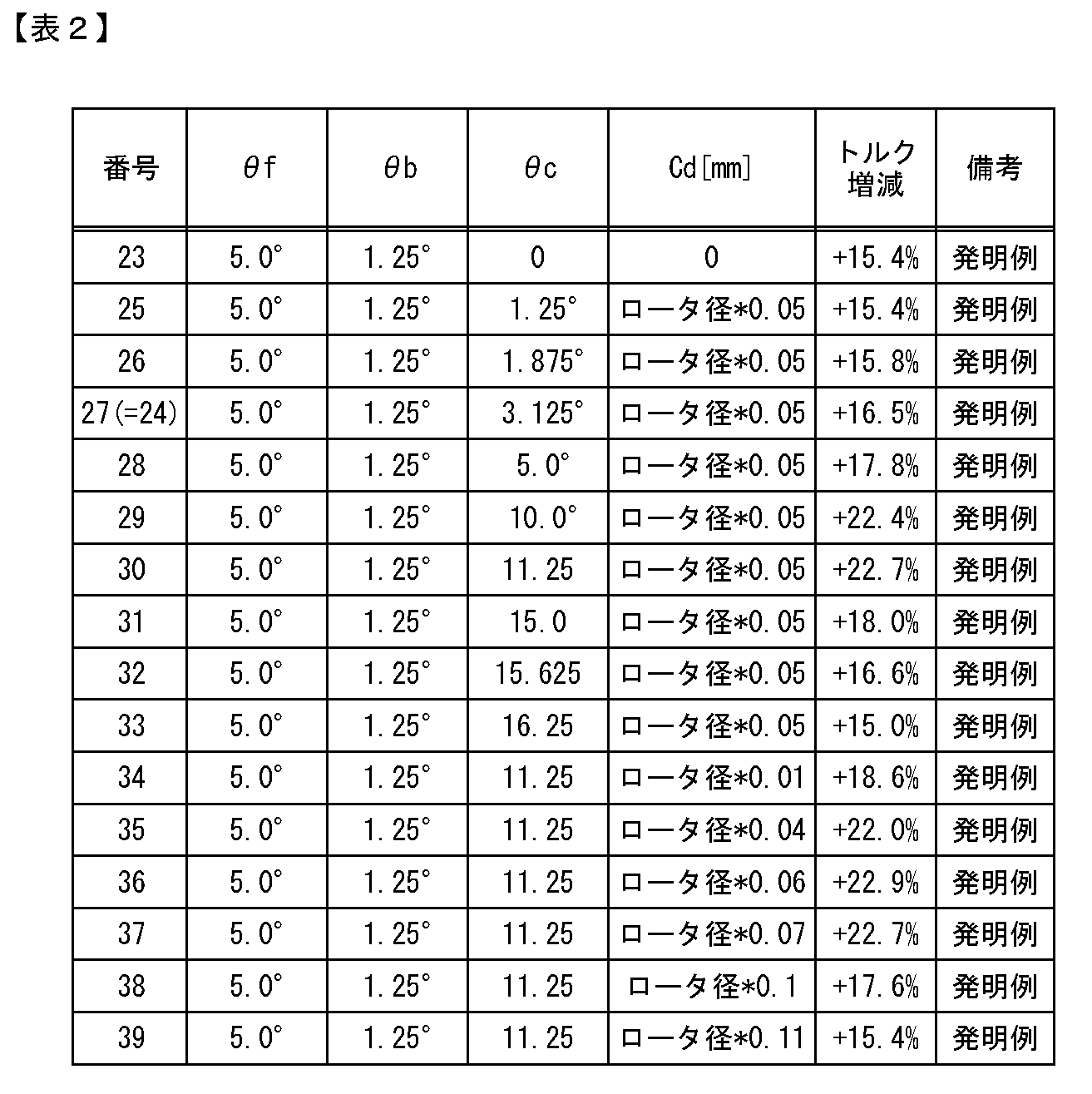
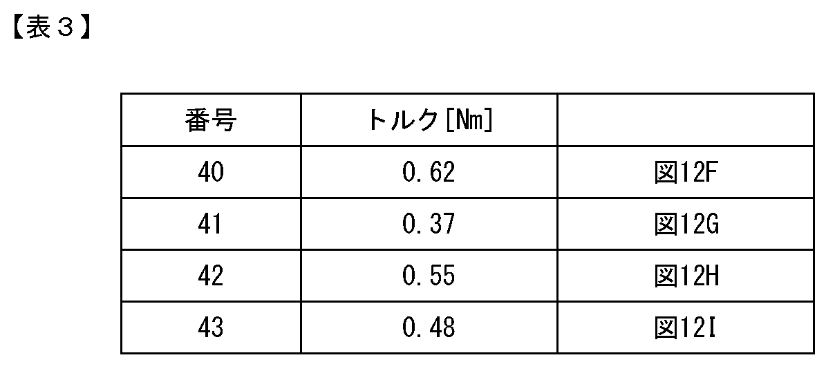
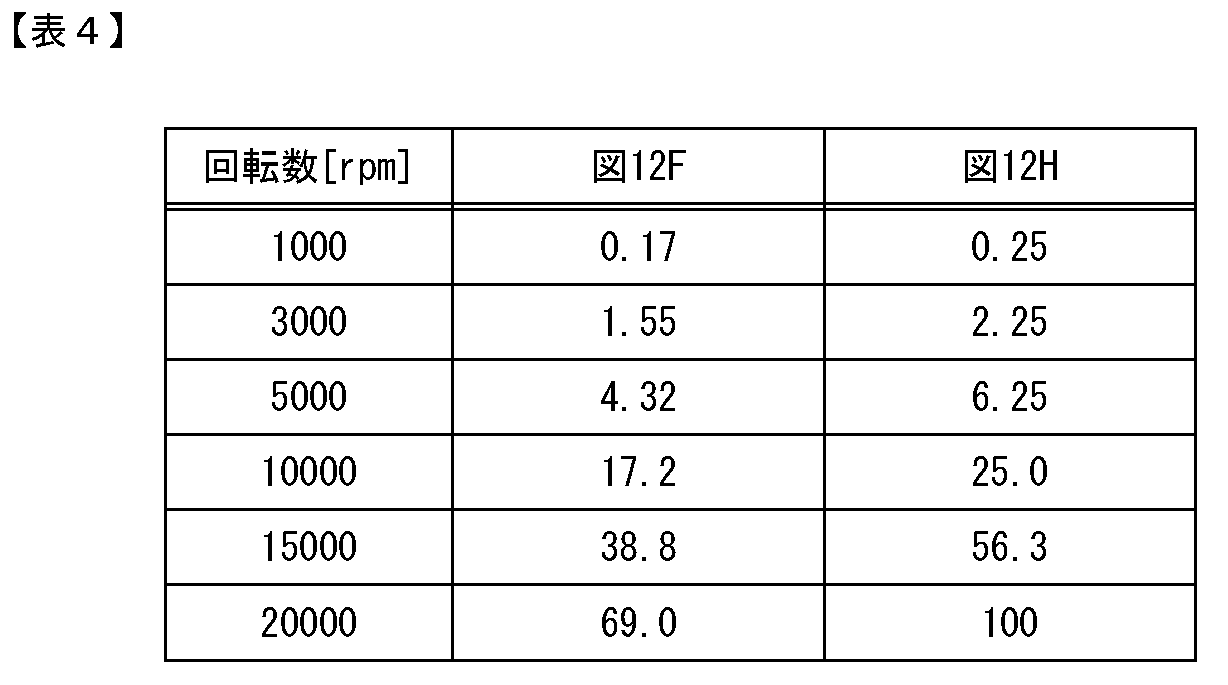
以上のように、図12Fに示すロータ(ロータコア)は、図12G~図12Iに示すロータ(ロータコア)に比べて、力学的および電磁気的に優位な形状であると言える。
以上のように本実施形態では、ロータコア断面において、開放端部前方側コーナ部1131a、1131cの位置が、基準位置831a~831bよりも、ロータコア811の回転方向の後方側にある。ここで、開放端部前方側コーナ部1131a、1131cは、ロータコア断面において、同一の極に設置される少なくとも一つの開放端部1111a~1111bの、ロータコア811の周方向における2つのコーナ部1131a~1131b、1131c~1131dのうち、ロータコア811の回転方向における前方側のコーナ部である。また、基準位置831a、831bは、それぞれ、当該開放端部1111a、1111bを有する磁石穴817a、817bに対する基準位置である。したがって、ロータ810のトルクを増加させることができる。
本実施形態では、1極当たり2個の永久磁石812a~812bを設ける場合を例示した。しかしながら、1極当たりの永久磁石の数は、1個であっても3個以上であっても良い。
[開示1]
軟磁性材料を用いて形成され、1極当たり少なくとも一つの磁石穴を有する軟磁性体部を備えたロータコアであって、
前記磁石穴は、当該磁石穴に設置される永久磁石に対し、当該永久磁石の磁化方向と回転の中心となる回転軸線に平行な方向とに垂直な左右方向の両側に、前方側フラックスバリアとなる空間および後方側フラックスバリアとなる空間を有し、
前記前方側フラックスバリアとなる空間および前記後方側フラックスバリアとなる空間のうち、少なくとも一つのフラックスバリアとなる空間は、前記ロータコアの外周面において開放されている開放端部を有し、
前記回転軸線に対して垂直な断面において、ロータの同一の極に設置される少なくとも一つの前記開放端部の開放端部前方側コーナ部の位置は、当該開放端部を有する前記磁石穴に対する基準位置よりも、前記ロータコアの回転方向の後方側にあり、
前記断面において、前記開放端部前方側コーナ部は、ロータの同一の極に設置される少なくとも一つの前記開放端部の、前記ロータコアの周方向における2つのコーナ部のうち、前記ロータコアの回転方向における前方側のコーナ部であり、
前記断面において、前記開放端部を有する前記磁石穴に対する基準位置は、当該磁石穴に設置される前記永久磁石のうち、当該開放端部に最も近い位置にある前記永久磁石の端部の一つである永久磁石基準端部と前記回転軸線とを通る直線と、前記ロータコアの外周面と、の交点の位置であり、
前記断面において、前記開放端部に最も近い位置にある前記永久磁石の前記永久磁石基準端部は、当該永久磁石の端部のうち、当該永久磁石を含む一つの極の領域の前記周方向における中心の位置と、前記回転軸線と、を通る直線からの前記周方向における距離が最も遠い位置にある端部であり、前記開放端部に最も近い位置にある前記永久磁石を含む一つの極の領域の前記周方向における中心の位置と、前記回転軸線と、を通る直線からの前記周方向における距離は、前記ロータコアの回転方向における前方側および後方側のうち、当該開放端部が存在する側において定められる距離である、ロータコア。
[開示2]
前記断面において、ロータの同一の極に設置される全ての前記開放端部の前記開放端部前方側コーナ部の位置は、当該開放端部を有する前記磁石穴に対する基準位置よりも、前記ロータコアの回転方向の後方側にある、開示1に記載のロータコア。
[開示3]
前記ロータコアは、1極当たり複数の磁極穴を有し、
前記複数の磁石穴は、前記回転方向の前方側に位置する前方側磁石穴と、前記回転方向の後方側に位置する後方側磁石穴と、を有し、
前記前方側磁石穴が有する前記前方側フラックスバリアとなる空間は、前記前方側磁石穴が有する前記後方側フラックスバリアとなる空間よりも前記回転方向の前方側且つ前記ロータコアの外周側にある外周側フラックスバリアであり、
前記後方側磁石穴が有する前記後方側フラックスバリアとなる空間は、前記後方側磁石穴が有する前記前方側フラックスバリアとなる空間よりも前記回転方向の後方側且つ前記ロータコアの外周側にある外周側フラックスバリアであり、
前記前方側磁石穴が有する前記前方側フラックスバリアとなる空間と、前記後方側磁石穴が有する前記後方側フラックスバリアとなる空間と、のうち、少なくとも一方のフラックスバリアとなる空間は、前記開放端部を有し、
前記断面において、前記開放端部前方側コーナ部は、前方側開放端部前方側コーナ部と、後方側開放端部前方側コーナ部と、のうちの少なくとも一方を有し、
前記断面において、前記前方側開放端部前方側コーナ部は、前方側開放端部の、前記ロータコアの周方向における2つのコーナ部のうち、前記回転方向の前方側のコーナ部であり、
前記断面において、前記前方側開放端部は、前記前方側磁石穴が有する前記前方側フラックスバリアとなる空間の前記開放端部であり、
前記断面において、前記後方側開放端部は、後方側開放端部の、前記ロータコアの周方向における2つのコーナ部のうち、前記回転方向の前方側のコーナ部であり、
前記断面において、前記後方側開放端部前方側コーナ部は、前記後方側磁石穴が有する前記後方側フラックスバリアとなる空間の前記開放端部であり、
前記断面において、前記永久磁石基準端部は、前方側永久磁石端部と、後方側永久磁石端部と、のうちの少なくとも一方を有し、
前記断面において、前記前方側永久磁石端部は、前記前方側磁石穴に設置される前記永久磁石の端部のうち、最も前記回転方向の前方側の位置の端部であり、
前記断面において、前記後方側永久磁石端部は、前記後方側磁石穴に設置される前記永久磁石の端部のうち、最も前記回転方向の後方側の位置の端部であり、
前記断面において、前記基準位置は、前方側基準位置と、後方側基準位置と、のうちの少なくとも一方を有し、
前記断面において、前記前方側基準位置は、前記前方側永久磁石端部と前記回転軸線とを通る直線と、前記ロータコアの外周面と、の交点の位置であり、
前記断面において、前記後方側基準位置は、前記後方側永久磁石端部と前記回転軸線とを通る直線と、前記ロータコアの外周面との交点の位置である、開示1または2に記載のロータコア。
[開示4]
前記開放端部前方側コーナ部は、前記前方側開放端部前方側コーナ部と、前記後方側開放端部前方側コーナ部と、を有し、
前記永久磁石基準端部は、前記前方側永久磁石端部と、前記後方側永久磁石端部と、を有し、
前記基準位置は、前記前方側基準位置と、前記後方側基準位置と、を有し、
前記前方側磁石穴が有する前記前方側フラックスバリアとなる空間と、前記後方側磁石穴が有する前記後方側フラックスバリアとなる空間と、のそれぞれが、前記開放端部を有する、開示3に記載のロータコア。
[開示5]
前記断面において、前記開放端部前方側コーナ部のうち、同一の極における前記周方向の中心よりも前記回転方向の前方側に位置する前記開放端部前方側コーナ部と前記回転軸線とを通る直線と、当該開放端部前方側コーナ部をコーナ部の一つとする前記開放端部を有する前記磁石穴に対する前記基準位置と前記回転軸線とを通る直線と、のなす角度は、θa/24以上15θa/24以下であり、
θaは、前記基準位置からの前記回転軸線周りの角度である移動角度(rad)であり、
θaは、2π/Nslotで算出され、
Nslotは、前記ロータコアの外周面と間隔を有して対向する位置に設置されるステータコアのスロット数(個)である、開示1~4のいずれか一つに記載のロータコア。
[開示6]
前記断面において、前記開放端部前方側コーナ部のうち、同一の極における前記周方向の中心よりも前記回転方向の後方側に位置する前記開放端部前方側コーナ部と前記回転軸線とを通る直線と、当該開放端部前方側コーナ部をコーナ部の一つとする前記開放端部を有する前記磁石穴に対する前記基準位置と前記回転軸線とを通る直線と、のなす角度は、θa/24以上θa/8以下であり、
θaは、前記基準位置からの前記回転軸線周りの角度である移動角度(rad)であり、
θaは、2π/Nslotで算出され、
Nslotは、前記ロータコアの外周面と間隔を有して対向する位置に設置されるステータコアのスロット数(個)である、開示1~5のいずれか一つに記載のロータコア。
[開示7]
前記開放端部の前記周方向の長さは、当該開放端部を有する前記磁石穴に設置される前記永久磁石の磁化方向の長さの0.1倍以上、1.0倍以下である、開示1~6のいずれか一つに記載のロータコア。
[開示8]
前記軟磁性体部は、前記フラックスバリアとなる空間とは異なる窪み部として、前記ロータコアの外周面において開放されている開放端部を有する窪み部をさらに有し、
前記窪み部は、前記ロータコアの外周面と間隔を有して対向する位置に設置されるステータコアのティースのうち磁束密度が最低となるティースとは異なるティースと間隔を有して対向する位置にある、開示1~7のいずれか一つに記載のロータコア。
[開示9]
前記断面において、前記窪み部の開放端部における2つのコーナ部のうち、前記回転方向の後方側のコーナ部である窪み部後方側コーナ部と前記回転軸線とを通る直線と、当該窪み部が設置される極と同一の極において当該窪み部よりも前記回転方向の後方側に位置する前記開放端部前方側コーナ部と前記回転軸線とを通る直線と、のなす角度は、θaであり、
前記窪み部の開放端部における2つのコーナ部のうち、前記回転方向の前方側のコーナ部である窪み部前方側コーナ部と前記回転軸線とを通る直線と、前記窪み部後方側コーナ部と前記回転軸線とを通る直線と、のなす角度は、θa/8以上、25θa/24θa以下であり、
θaは、前記断面において、後方側永久磁石端部と前記回転軸線とを通る直線と、前記ロータコアの外周面と、の交点の位置である後方側基準位置からの前記回転軸線周りの角度である移動角度(rad)であり、
前記後方側永久磁石端部は、同一の極に設置される前記永久磁石の端部のうち、前記周方向の最も後方側に位置する端部であり、
θaは、2π/Nslotで算出され、
Nslotは、前記ロータコアの外周面と間隔を有して対向する位置に設置されるステータコアのスロット数(個)である、開示8に記載のロータコア。
[開示10]
前記窪み部の深さの最大値は、前記ロータコアの直径の0.01倍以上0.1倍以下の範囲内である、開示8または9に記載のロータコア。
[開示11]
前記ロータコアは、1極当たり複数の磁極穴を有し、
前記複数の磁石穴は、前記回転方向の前方側に位置する前方側磁石穴と、前記回転方向の後方側に位置する後方側磁石穴と、を有し、
前記前方側磁石穴が有する前記前方側フラックスバリアとなる空間は、前記前方側磁石穴が有する前記後方側フラックスバリアとなる空間よりも前記回転方向の前方側にあり、
前記後方側磁石穴が有する前記前方側フラックスバリアとなる空間は、前記後方側磁石穴が有する前記後方側フラックスバリアとなる空間よりも前記回転方向の後方側にあり、
前記軟磁性体部は、前記前方側磁石穴が有する前記後方側フラックスバリアとなる空間と、前記後方側磁石穴が有する前記後方側フラックスバリアとなる空間との間の領域に配置された磁石間ブリッジ部を有し、
前記前方側磁石穴は、当該前方側磁石穴に設置される前記永久磁石に対し前記回転方向の前方側に前記開放端部となる第1端部を有し、
前記前方側磁石穴は、当該前方側磁石穴に設置される前記永久磁石に対し前記回転方向の後方側に第2端部を有し、
前記後方側磁石穴は、当該後方側磁石穴に設置される前記永久磁石に対し前記回転方向の後方側に前記開放端部となる第1端部を有し、
前記後方側磁石穴は、当該後方側磁石穴に設置される前記永久磁石に対し前記回転方向の前方側に第2端部を有し、
前記前方側磁石穴および前記後方側磁石穴の各々の前記第2端部は、フラックスバリアとなる空間の端部と一致し、且つ、閉鎖されている、開示1~10のいずれか一つに記載のロータコア。
[開示12]
前記断面において、ブリッジ幅規定線の、前記軟磁性材料と重なる部分の長さは、前記ロータコアの直径の0.02倍以下であり、
前記ブリッジ幅規定線は、前記前方側磁石穴および前記後方側磁石穴の前記第2端部同士を、前記軟磁性材料と重なる長さが最短になるように結ぶ直線である、開示11に記載のロータコア。
[開示13]
前記断面において、前記前方側磁石穴および前記後方側磁石穴の各々は、当該前方側磁石穴および当該後方側磁石穴に設置される前記永久磁石の磁化方向で外周側に位置する第3端部と、前記第3端部よりも当該永久磁石の磁化方向で内周側に位置する第4端部と、をさらに有し、
前記断面において、ブリッジ幅規定線の、前記軟磁性材料と重なる部分の長さは、wminを上回り、
前記ブリッジ幅規定線は、前記前方側磁石穴および前記後方側磁石穴の前記第2端部同士を、前記軟磁性材料と重なる長さが最短になるように結ぶ直線であり、
wminは、ρ×S×rg×ω÷Ysで算出され、
ρは、前記軟磁性材料の密度(kg/m3)であり、
Ysは、前記軟磁性材料の常温における降伏応力(Pa)であり、
Sは、外力影響部の面積(m2)であり、
前記外力影響部は、前記断面において、前記ブリッジ幅規定線の一方の端に位置する前記前方側磁石穴の前記第3端部と、前記ブリッジ幅規定線の他方の端に位置する前記後方側磁石穴の前記第3端部と、前記軟磁性体部の外周面と、前記ブリッジ幅規定線と、により囲まれる前記軟磁性材料の領域であり、
rgは、前記断面における前記外力影響部の重心の位置と前記回転の中心との半径方向における距離(m)であり、
ωは、最高回転数で回転するときのロータの角速度(rad/sec)である、開示11または12に記載のロータコア。
[開示14]
軟磁性材料を用いて形成され、1極当たり少なくとも一つの磁石穴を有する軟磁性体部を備えたロータコアであって、
前記軟磁性体部は、外周面に窪み部を有し、
前記磁石穴は、当該磁石穴に設置される永久磁石の磁化方向と回転の中心となる回転軸線に平行な方向とに垂直な左右方向に第1端部および第2端部を有し、
前記第1端部および前記第2端部のうち、少なくとも一方の端部は開放されている開放端部であり、
前記窪み部は、前記開放端部とは異なる位置にあり、
前記窪み部は、前記ロータコアの外周面と間隔を有して対向する位置に設置されるステータコアのティースのうち磁束密度が最低となるティースとは異なるティースと間隔を有して対向する位置にある、ロータコア。
[開示15]
前記断面において、前記窪み部の開放端部における2つのコーナ部のうち、前記ロータコアの回転方向の後方側のコーナ部である窪み部後方側コーナ部と前記回転軸線とを通る直線と、当該窪み部が設置される極と同一の極において当該窪み部よりも前記回転方向の後方側に位置する開放端部前方側コーナ部と前記回転軸線とを通る直線と、のなす角度は、θaであり、
前記断面において、前記開放端部前方側コーナ部は、ロータの同一の極に設置される少なくとも一つの前記開放端部の、前記ロータコアの周方向における2つのコーナ部のうち、前記ロータコアの回転方向における前方側のコーナ部であり、
前記窪み部の開放端部における2つのコーナ部のうち、前記回転方向の前方側のコーナ部である窪み部前方側コーナ部と前記回転軸線とを通る直線と、前記窪み部後方側コーナ部と前記回転軸線とを通る直線と、のなす角度は、θa/8以上、25θa/24θa以下であり、
θaは、前記断面において、後方側永久磁石端部と前記回転軸線とを通る直線と、前記ロータコアの外周面と、の交点の位置である後方側基準位置からの前記回転軸線周りの角度である移動角度(rad)であり、
前記後方側永久磁石端部は、同一の極に設置される前記永久磁石の端部のうち、前記周方向の最も後方側に位置する端部であり、
θaは、2π/Nslotで算出され、
Nslotは、前記ロータコアの外周面と間隔を有して対向する位置に設置されるステータコアのスロット数(個)である、開示14に記載のロータコア。
[開示16]
前記窪み部の深さの最大値は、前記ロータコアの直径の0.01倍以上0.1倍以下の範囲内である、開示14または15に記載のロータコア。
[開示17]
開示1~16のいずれか一つに記載のロータコアと、
前記ロータコアに設置される複数の永久磁石と、
を備える、ロータ。
[開示18]
前記永久磁石の常温における残留磁束密度は、0.8T以下である、開示17に記載のロータ。
[開示19]
前記永久磁石は、レアアースを含有しない、開示17または18に記載のロータ。
[開示20]
開示17~19のいずれか一つに記載のロータと、
ステータと、
を備える、回転電機。
Claims (18)
- 軟磁性材料を用いて形成され、1極当たり少なくとも一つの磁石穴を有する軟磁性体部を備えたロータコアであって、
前記磁石穴は、当該磁石穴に設置される永久磁石に対し、当該永久磁石の磁化方向と回転の中心となる回転軸線に平行な方向とに垂直な左右方向の両側に、前方側フラックスバリアとなる空間および後方側フラックスバリアとなる空間を有し、
前記前方側フラックスバリアとなる空間および前記後方側フラックスバリアとなる空間のうち、少なくとも一つのフラックスバリアとなる空間は、前記ロータコアの外周面において開放されている開放端部を有し、
前記回転軸線に対して垂直な断面において、ロータの同一の極に設置される少なくとも一つの前記開放端部の開放端部前方側コーナ部の位置は、当該開放端部を有する前記磁石穴に対する基準位置よりも、前記ロータコアの回転方向の後方側にあり、
前記断面において、前記開放端部前方側コーナ部は、ロータの同一の極に設置される少なくとも一つの前記開放端部の、前記ロータコアの周方向における2つのコーナ部のうち、前記ロータコアの回転方向における前方側のコーナ部であり、
前記断面において、前記開放端部を有する前記磁石穴に対する基準位置は、当該磁石穴に設置される前記永久磁石のうち、当該開放端部に最も近い位置にある前記永久磁石の端部の一つである永久磁石基準端部と前記回転軸線とを通る直線と、前記ロータコアの外周面と、の交点の位置であり、
前記断面において、前記開放端部に最も近い位置にある前記永久磁石の前記永久磁石基準端部は、当該永久磁石の端部のうち、当該永久磁石を含む一つの極の領域の前記周方向における中心の位置と、前記回転軸線と、を通る直線からの前記周方向における距離が最も遠い位置にある端部であり、
前記開放端部に最も近い位置にある前記永久磁石を含む一つの極の領域の前記周方向における中心の位置と、前記回転軸線と、を通る直線からの前記周方向における距離は、前記ロータコアの回転方向における前方側および後方側のうち、当該開放端部が存在する側において定められる距離である、ロータコア。 - 前記断面において、ロータの同一の極に設置される全ての前記開放端部の前記開放端部前方側コーナ部の位置は、当該開放端部を有する前記磁石穴に対する基準位置よりも、前記ロータコアの回転方向の後方側にある、請求項1に記載のロータコア。
- 前記ロータコアは、1極当たり複数の磁極穴を有し、
前記複数の磁石穴は、前記回転方向の前方側に位置する前方側磁石穴と、前記回転方向の後方側に位置する後方側磁石穴と、を有し、
前記前方側磁石穴が有する前記前方側フラックスバリアとなる空間は、前記前方側磁石穴が有する前記後方側フラックスバリアとなる空間よりも前記回転方向の前方側且つ前記ロータコアの外周側にある外周側フラックスバリアであり、
前記後方側磁石穴が有する前記後方側フラックスバリアとなる空間は、前記後方側磁石穴が有する前記前方側フラックスバリアとなる空間よりも前記回転方向の後方側且つ前記ロータコアの外周側にある外周側フラックスバリアであり、
前記前方側磁石穴が有する前記前方側フラックスバリアとなる空間と、前記後方側磁石穴が有する前記後方側フラックスバリアとなる空間と、のうち、少なくとも一方のフラックスバリアとなる空間は、前記開放端部を有し、
前記断面において、前記開放端部前方側コーナ部は、前方側開放端部前方側コーナ部と、後方側開放端部前方側コーナ部と、のうちの少なくとも一方を有し、
前記断面において、前記前方側開放端部前方側コーナ部は、前方側開放端部の、前記ロータコアの周方向における2つのコーナ部のうち、前記回転方向の前方側のコーナ部であり、
前記断面において、前記前方側開放端部は、前記前方側磁石穴が有する前記前方側フラックスバリアとなる空間の前記開放端部であり、
前記断面において、前記後方側開放端部は、後方側開放端部の、前記ロータコアの周方向における2つのコーナ部のうち、前記回転方向の前方側のコーナ部であり、
前記断面において、前記後方側開放端部前方側コーナ部は、前記後方側磁石穴が有する前記後方側フラックスバリアとなる空間の前記開放端部であり、
前記断面において、前記永久磁石基準端部は、前方側永久磁石端部と、後方側永久磁石端部と、のうちの少なくとも一方を有し、
前記断面において、前記前方側永久磁石端部は、前記前方側磁石穴に設置される前記永久磁石の端部のうち、最も前記回転方向の前方側の位置の端部であり、
前記断面において、前記後方側永久磁石端部は、前記後方側磁石穴に設置される前記永久磁石の端部のうち、最も前記回転方向の後方側の位置の端部であり、
前記断面において、前記基準位置は、前方側基準位置と、後方側基準位置と、のうちの少なくとも一方を有し、
前記断面において、前記前方側基準位置は、前記前方側永久磁石端部と前記回転軸線とを通る直線と、前記ロータコアの外周面と、の交点の位置であり、
前記断面において、前記後方側基準位置は、前記後方側永久磁石端部と前記回転軸線とを通る直線と、前記ロータコアの外周面との交点の位置である、請求項1または2に記載のロータコア。 - 前記開放端部前方側コーナ部は、前記前方側開放端部前方側コーナ部と、前記後方側開放端部前方側コーナ部と、を有し、
前記永久磁石基準端部は、前記前方側永久磁石端部と、前記後方側永久磁石端部と、を有し、
前記基準位置は、前記前方側基準位置と、前記後方側基準位置と、を有し、
前記前方側磁石穴が有する前記前方側フラックスバリアとなる空間と、前記後方側磁石穴が有する前記後方側フラックスバリアとなる空間と、のそれぞれが、前記開放端部を有する、請求項3に記載のロータコア。 - 前記断面において、前記開放端部前方側コーナ部のうち、同一の極における前記周方向の中心よりも前記回転方向の前方側に位置する前記開放端部前方側コーナ部と前記回転軸線とを通る直線と、当該開放端部前方側コーナ部をコーナ部の一つとする前記開放端部を有する前記磁石穴に対する前記基準位置と前記回転軸線とを通る直線と、のなす角度は、θa/24以上15θa/24以下であり、
θaは、前記基準位置からの前記回転軸線周りの角度である移動角度(rad)であり、
θaは、2π/Nslotで算出され、
Nslotは、前記ロータコアの外周面と間隔を有して対向する位置に設置されるステータコアのスロット数(個)である、請求項1~4のいずれか1項に記載のロータコア。 - 前記断面において、前記開放端部前方側コーナ部のうち、同一の極における前記周方向の中心よりも前記回転方向の後方側に位置する前記開放端部前方側コーナ部と前記回転軸線とを通る直線と、当該開放端部前方側コーナ部をコーナ部の一つとする前記開放端部を有する前記磁石穴に対する前記基準位置と前記回転軸線とを通る直線と、のなす角度は、θa/24以上θa/8以下であり、
θaは、前記基準位置からの前記回転軸線周りの角度である移動角度(rad)であり、
θaは、2π/Nslotで算出され、
Nslotは、前記ロータコアの外周面と間隔を有して対向する位置に設置されるステータコアのスロット数(個)である、請求項1~5のいずれか1項に記載のロータコア。 - 前記開放端部の前記周方向の長さは、当該開放端部を有する前記磁石穴に設置される前記永久磁石の磁化方向の長さの0.1倍以上、1.0倍以下である、請求項1~6のいずれか1項に記載のロータコア。
- 前記軟磁性体部は、前記フラックスバリアとなる空間とは異なる窪み部として、前記ロータコアの外周面において開放されている開放端部を有する窪み部をさらに有し、
前記窪み部は、前記ロータコアの外周面と間隔を有して対向する位置に設置されるステータコアのティースのうち磁束密度が最低となるティースとは異なるティースと間隔を有して対向する位置にある、請求項1~7のいずれか1項に記載のロータコア。 - 前記断面において、前記窪み部の開放端部における2つのコーナ部のうち、前記回転方向の後方側のコーナ部である窪み部後方側コーナ部と前記回転軸線とを通る直線と、当該窪み部が設置される極と同一の極において当該窪み部よりも前記回転方向の後方側に位置する前記開放端部前方側コーナ部と前記回転軸線とを通る直線と、のなす角度は、θaであり、
前記窪み部の開放端部における2つのコーナ部のうち、前記回転方向の前方側のコーナ部である窪み部前方側コーナ部と前記回転軸線とを通る直線と、前記窪み部後方側コーナ部と前記回転軸線とを通る直線と、のなす角度は、θa/8以上、25θa/24θa以下であり、
θaは、前記断面において、後方側永久磁石端部と前記回転軸線とを通る直線と、前記ロータコアの外周面と、の交点の位置である後方側基準位置からの前記回転軸線周りの角度である移動角度(rad)であり、
前記後方側永久磁石端部は、同一の極に設置される前記永久磁石の端部のうち、前記周方向の最も後方側に位置する端部であり、
θaは、2π/Nslotで算出され、
Nslotは、前記ロータコアの外周面と間隔を有して対向する位置に設置されるステータコアのスロット数(個)である、請求項8に記載のロータコア。 - 前記窪み部の深さの最大値は、前記ロータコアの直径の0.01倍以上0.1倍以下の範囲内である、請求項8または9に記載のロータコア。
- 前記ロータコアは、1極当たり複数の磁極穴を有し、
前記複数の磁石穴は、前記回転方向の前方側に位置する前方側磁石穴と、前記回転方向の後方側に位置する後方側磁石穴と、を有し、
前記前方側磁石穴が有する前記前方側フラックスバリアとなる空間は、前記前方側磁石穴が有する前記後方側フラックスバリアとなる空間よりも前記回転方向の前方側にあり、
前記後方側磁石穴が有する前記前方側フラックスバリアとなる空間は、前記後方側磁石穴が有する前記後方側フラックスバリアとなる空間よりも前記回転方向の後方側にあり、
前記軟磁性体部は、前記前方側磁石穴が有する前記後方側フラックスバリアとなる空間と、前記後方側磁石穴が有する前記後方側フラックスバリアとなる空間との間の領域に配置された磁石間ブリッジ部を有し、
前記前方側磁石穴は、当該前方側磁石穴に設置される前記永久磁石に対し前記回転方向の前方側に前記開放端部となる第1端部を有し、
前記前方側磁石穴は、当該前方側磁石穴に設置される前記永久磁石に対し前記回転方向の後方側に第2端部を有し、
前記後方側磁石穴は、当該後方側磁石穴に設置される前記永久磁石に対し前記回転方向の後方側に前記開放端部となる第1端部を有し、
前記後方側磁石穴は、当該後方側磁石穴に設置される前記永久磁石に対し前記回転方向の前方側に第2端部を有し、
前記前方側磁石穴および前記後方側磁石穴の各々の前記第2端部は、フラックスバリアとなる空間の端部と一致し、且つ、閉鎖されている、請求項1~10のいずれか1項に記載のロータコア。 - 前記断面において、ブリッジ幅規定線の、前記軟磁性材料と重なる部分の長さは、前記ロータコアの直径の0.02倍以下であり、
前記ブリッジ幅規定線は、前記前方側磁石穴および前記後方側磁石穴の前記第2端部同士を、前記軟磁性材料と重なる長さが最短になるように結ぶ直線である、請求項11に記載のロータコア。 - 前記断面において、前記前方側磁石穴および前記後方側磁石穴の各々は、当該前方側磁石穴および当該後方側磁石穴に設置される前記永久磁石の磁化方向で外周側に位置する第3端部と、前記第3端部よりも当該永久磁石の磁化方向で内周側に位置する第4端部と、をさらに有し、
前記断面において、ブリッジ幅規定線の、前記軟磁性材料と重なる部分の長さは、wminを上回り、
前記ブリッジ幅規定線は、前記前方側磁石穴および前記後方側磁石穴の前記第2端部同士を、前記軟磁性材料と重なる長さが最短になるように結ぶ直線であり、
wminは、ρ×S×rg×ω÷Ysで算出され、
ρは、前記軟磁性材料の密度(kg/m3)であり、
Ysは、前記軟磁性材料の常温における降伏応力(Pa)であり、
Sは、外力影響部の面積(m2)であり、
前記外力影響部は、前記断面において、前記ブリッジ幅規定線の一方の端に位置する前記前方側磁石穴の前記第3端部と、前記ブリッジ幅規定線の他方の端に位置する前記後方側磁石穴の前記第3端部と、前記軟磁性体部の外周面と、前記ブリッジ幅規定線と、により囲まれる前記軟磁性材料の領域であり、
rgは、前記断面における前記外力影響部の重心の位置と前記回転の中心との半径方向における距離(m)であり、
ωは、最高回転数で回転するときのロータの角速度(rad/sec)である、請求項11または12に記載のロータコア。 - 軟磁性材料を用いて形成され、1極当たり少なくとも一つの磁石穴を有する軟磁性体部を備えたロータコアであって、
前記軟磁性体部は、外周面に窪み部を有し、
前記磁石穴は、当該磁石穴に設置される永久磁石の磁化方向と回転の中心となる回転軸線に平行な方向とに垂直な左右方向に第1端部および第2端部を有し、
前記第1端部および前記第2端部のうち、少なくとも一方の端部は開放されている開放端部であり、
前記窪み部は、前記開放端部とは異なる位置にあり、
前記窪み部は、前記ロータコアの外周面と間隔を有して対向する位置に設置されるステータコアのティースのうち磁束密度が最低となるティースとは異なるティースと間隔を有して対向する位置にある、ロータコア。 - 請求項1~14のいずれか1項に記載のロータコアと、
前記ロータコアに設置される複数の永久磁石と、
を備える、ロータ。 - 前記永久磁石の常温における残留磁束密度は、0.8T以下である、請求項15に記載のロータ。
- 前記永久磁石は、レアアースを含有しない、請求項15または16に記載のロータ。
- 請求項15~17のいずれか1項に記載のロータと、
ステータと、
を備える、回転電機。
Priority Applications (7)
| Application Number | Priority Date | Filing Date | Title |
|---|---|---|---|
| JP2023559464A JP7667496B2 (ja) | 2021-11-15 | 2022-09-29 | ロータコア、ロータ、および回転電機 |
| US18/689,719 US20250132619A1 (en) | 2021-11-15 | 2022-09-29 | Rotor core, rotor, and rotary electric machine |
| MX2024004348A MX2024004348A (es) | 2021-11-15 | 2022-09-29 | Nucleo de rotor, rotor y maquina electrica giratoria. |
| KR1020247013925A KR102960030B1 (ko) | 2021-11-15 | 2022-09-29 | 로터 코어, 로터 및 회전 전기 기기 |
| CA3229772A CA3229772A1 (en) | 2021-11-15 | 2022-09-29 | Rotor core, rotor, and rotary electric machine |
| EP22892438.7A EP4436011A4 (en) | 2021-11-15 | 2022-09-29 | Rotor core, rotor, and rotating electrical machine |
| CN202280074505.5A CN118251825A (zh) | 2021-11-15 | 2022-09-29 | 转子铁芯、转子以及旋转电机 |
Applications Claiming Priority (2)
| Application Number | Priority Date | Filing Date | Title |
|---|---|---|---|
| JP2021-185697 | 2021-11-15 | ||
| JP2021185697 | 2021-11-15 |
Publications (1)
| Publication Number | Publication Date |
|---|---|
| WO2023084937A1 true WO2023084937A1 (ja) | 2023-05-19 |
Family
ID=86335491
Family Applications (1)
| Application Number | Title | Priority Date | Filing Date |
|---|---|---|---|
| PCT/JP2022/036391 Ceased WO2023084937A1 (ja) | 2021-11-15 | 2022-09-29 | ロータコア、ロータ、および回転電機 |
Country Status (8)
| Country | Link |
|---|---|
| US (1) | US20250132619A1 (ja) |
| EP (1) | EP4436011A4 (ja) |
| JP (1) | JP7667496B2 (ja) |
| CN (1) | CN118251825A (ja) |
| CA (1) | CA3229772A1 (ja) |
| MX (1) | MX2024004348A (ja) |
| TW (1) | TWI818755B (ja) |
| WO (1) | WO2023084937A1 (ja) |
Cited By (2)
| Publication number | Priority date | Publication date | Assignee | Title |
|---|---|---|---|---|
| WO2025094273A1 (ja) * | 2023-10-31 | 2025-05-08 | 株式会社 東芝 | 回転子および回転電機 |
| RU2856076C1 (ru) * | 2025-08-05 | 2026-02-10 | Общество С Ограниченной Ответственностью "Амт" | Ротор синхронной электрической машины и способ управления его характеристиками |
Families Citing this family (1)
| Publication number | Priority date | Publication date | Assignee | Title |
|---|---|---|---|---|
| US12592597B2 (en) * | 2023-11-15 | 2026-03-31 | GM Global Technology Operations LLC | Selective permeability rotor structure for interior permanent magnet machine |
Citations (11)
| Publication number | Priority date | Publication date | Assignee | Title |
|---|---|---|---|---|
| JP2011217602A (ja) * | 2010-03-31 | 2011-10-27 | Valeo Equipments Electriques Moteur | 永久磁石を備える、磁束収束タイプの同期回転電気機械 |
| JP2012050274A (ja) * | 2010-08-28 | 2012-03-08 | Mitsubishi Electric Corp | 同期電動機の回転子 |
| JP2012060773A (ja) * | 2010-09-08 | 2012-03-22 | Mitsubishi Electric Corp | 同期電動機の回転子 |
| JP2012205472A (ja) * | 2011-03-28 | 2012-10-22 | Toyota Industries Corp | 回転電機の永久磁石埋設型回転子及び回転電機 |
| JP2012228072A (ja) * | 2011-04-20 | 2012-11-15 | Mitsubishi Electric Corp | 永久磁石型回転電機およびその製造方法 |
| JP2013046421A (ja) * | 2011-08-21 | 2013-03-04 | Toyota Industries Corp | 永久磁石埋設型電動モータ |
| JP2014128116A (ja) * | 2012-12-26 | 2014-07-07 | Toyota Industries Corp | 永久磁石埋設型回転電機 |
| WO2015076045A1 (ja) * | 2013-11-20 | 2015-05-28 | 日立オートモティブシステムズ株式会社 | 回転電機、およびその回転電機を備えた電動車両 |
| JP2019057984A (ja) | 2017-09-20 | 2019-04-11 | 株式会社豊田自動織機 | 永久磁石式回転電機のロータ |
| JP2021114099A (ja) | 2020-01-17 | 2021-08-05 | 日本製鉄株式会社 | コア設計装置、コア設計方法、およびプログラム |
| JP2021185697A (ja) | 2016-06-20 | 2021-12-09 | オッポ広東移動通信有限公司Guangdong Oppo Mobile Telecommunications Corp., Ltd. | 情報伝送方法及び装置 |
Family Cites Families (10)
| Publication number | Priority date | Publication date | Assignee | Title |
|---|---|---|---|---|
| JP2007097387A (ja) * | 2005-08-31 | 2007-04-12 | Toshiba Corp | 回転電機 |
| JP5806073B2 (ja) * | 2010-10-19 | 2015-11-10 | アスモ株式会社 | ブラシレスモータ |
| JP5488625B2 (ja) * | 2012-02-13 | 2014-05-14 | 株式会社デンソー | ダブルステータ型同期モータ |
| JP5958305B2 (ja) * | 2012-11-29 | 2016-07-27 | スズキ株式会社 | Ipm型電動回転機 |
| JP6894663B2 (ja) * | 2015-10-29 | 2021-06-30 | 株式会社富士通ゼネラル | 回転子および永久磁石電動機 |
| TW201728768A (zh) * | 2016-02-10 | 2017-08-16 | 日新製鋼股份有限公司 | 永久磁鐵內嵌式馬達的轉子鐵芯用鋼板及其製造方法、永久磁鐵內嵌式馬達的轉子鐵芯以及永久磁鐵內嵌式馬達 |
| KR20180136524A (ko) * | 2016-06-22 | 2018-12-24 | 미쓰비시덴키 가부시키가이샤 | 컨시퀀트폴형의 회전자, 전동기 및 공기 조화기 |
| CN113994569B (zh) * | 2019-09-24 | 2024-07-30 | 株式会社东芝 | 旋转电机的转子 |
| KR102726810B1 (ko) * | 2020-02-24 | 2024-11-05 | 현대자동차주식회사 | 모터의 회전자 |
| TWM617436U (zh) * | 2021-06-04 | 2021-09-21 | 士林電機廠股份有限公司 | 馬達之磁石固定結構 |
-
2022
- 2022-09-29 EP EP22892438.7A patent/EP4436011A4/en active Pending
- 2022-09-29 MX MX2024004348A patent/MX2024004348A/es unknown
- 2022-09-29 CN CN202280074505.5A patent/CN118251825A/zh active Pending
- 2022-09-29 US US18/689,719 patent/US20250132619A1/en active Pending
- 2022-09-29 CA CA3229772A patent/CA3229772A1/en active Pending
- 2022-09-29 JP JP2023559464A patent/JP7667496B2/ja active Active
- 2022-09-29 WO PCT/JP2022/036391 patent/WO2023084937A1/ja not_active Ceased
- 2022-10-03 TW TW111137556A patent/TWI818755B/zh active
Patent Citations (11)
| Publication number | Priority date | Publication date | Assignee | Title |
|---|---|---|---|---|
| JP2011217602A (ja) * | 2010-03-31 | 2011-10-27 | Valeo Equipments Electriques Moteur | 永久磁石を備える、磁束収束タイプの同期回転電気機械 |
| JP2012050274A (ja) * | 2010-08-28 | 2012-03-08 | Mitsubishi Electric Corp | 同期電動機の回転子 |
| JP2012060773A (ja) * | 2010-09-08 | 2012-03-22 | Mitsubishi Electric Corp | 同期電動機の回転子 |
| JP2012205472A (ja) * | 2011-03-28 | 2012-10-22 | Toyota Industries Corp | 回転電機の永久磁石埋設型回転子及び回転電機 |
| JP2012228072A (ja) * | 2011-04-20 | 2012-11-15 | Mitsubishi Electric Corp | 永久磁石型回転電機およびその製造方法 |
| JP2013046421A (ja) * | 2011-08-21 | 2013-03-04 | Toyota Industries Corp | 永久磁石埋設型電動モータ |
| JP2014128116A (ja) * | 2012-12-26 | 2014-07-07 | Toyota Industries Corp | 永久磁石埋設型回転電機 |
| WO2015076045A1 (ja) * | 2013-11-20 | 2015-05-28 | 日立オートモティブシステムズ株式会社 | 回転電機、およびその回転電機を備えた電動車両 |
| JP2021185697A (ja) | 2016-06-20 | 2021-12-09 | オッポ広東移動通信有限公司Guangdong Oppo Mobile Telecommunications Corp., Ltd. | 情報伝送方法及び装置 |
| JP2019057984A (ja) | 2017-09-20 | 2019-04-11 | 株式会社豊田自動織機 | 永久磁石式回転電機のロータ |
| JP2021114099A (ja) | 2020-01-17 | 2021-08-05 | 日本製鉄株式会社 | コア設計装置、コア設計方法、およびプログラム |
Cited By (2)
| Publication number | Priority date | Publication date | Assignee | Title |
|---|---|---|---|---|
| WO2025094273A1 (ja) * | 2023-10-31 | 2025-05-08 | 株式会社 東芝 | 回転子および回転電機 |
| RU2856076C1 (ru) * | 2025-08-05 | 2026-02-10 | Общество С Ограниченной Ответственностью "Амт" | Ротор синхронной электрической машины и способ управления его характеристиками |
Also Published As
| Publication number | Publication date |
|---|---|
| JPWO2023084937A1 (ja) | 2023-05-19 |
| US20250132619A1 (en) | 2025-04-24 |
| CA3229772A1 (en) | 2023-05-19 |
| MX2024004348A (es) | 2024-04-25 |
| TW202322520A (zh) | 2023-06-01 |
| JP7667496B2 (ja) | 2025-04-23 |
| TWI818755B (zh) | 2023-10-11 |
| EP4436011A1 (en) | 2024-09-25 |
| CN118251825A (zh) | 2024-06-25 |
| EP4436011A4 (en) | 2025-03-05 |
| KR20240067956A (ko) | 2024-05-17 |
Similar Documents
| Publication | Publication Date | Title |
|---|---|---|
| JP5714189B2 (ja) | 回転子およびその回転子を備えた回転電機 | |
| US10256708B2 (en) | Electric machine | |
| WO2023084937A1 (ja) | ロータコア、ロータ、および回転電機 | |
| US11264849B2 (en) | Rotor for an electric machine | |
| JPWO2019064801A1 (ja) | 永久磁石式回転電機 | |
| JP5360219B2 (ja) | 回転子、永久磁石形同期回転電機、車両、昇降機、流体機械、および加工機 | |
| JP7758062B2 (ja) | 電気回転機械のロータ、及び当該ロータを備える電気回転機械 | |
| WO2007026802A1 (ja) | 回転電機 | |
| JP6821022B2 (ja) | 回転電機の回転子 | |
| JP2013128384A (ja) | 永久磁石同期電動機の回転子、電動機および工作機械 | |
| US9369016B2 (en) | Rotor for an electric machine comprising recesses in magnet pockets | |
| JP4027591B2 (ja) | 同期リラクタンスモータ | |
| JP4964291B2 (ja) | 永久磁石埋込型モータの回転子及び送風機及び圧縮機 | |
| JP6785522B1 (ja) | 回転電機 | |
| JP2001069701A (ja) | 磁石モータ | |
| JPWO2023084937A5 (ja) | ||
| JP7007651B2 (ja) | 回転子およびそれを備えた回転電気機械 | |
| KR102960030B1 (ko) | 로터 코어, 로터 및 회전 전기 기기 | |
| RU2840350C9 (ru) | Сердечник ротора, ротор и вращающаяся электрическая машина | |
| RU2840350C2 (ru) | Сердечник ротора, ротор и вращающаяся электрическая машина | |
| JP2013128405A (ja) | 永久磁石同期電動機の回転子、電動機および工作機械 | |
| US12218549B2 (en) | Rotary electric machine | |
| JP6492951B2 (ja) | ロータ、および、それを用いたモータ | |
| RU2853108C2 (ru) | Сердечник ротора, ротор и вращающаяся электрическая машина | |
| CN212486223U (zh) | 转子及马达 |
Legal Events
| Date | Code | Title | Description |
|---|---|---|---|
| 121 | Ep: the epo has been informed by wipo that ep was designated in this application |
Ref document number: 22892438 Country of ref document: EP Kind code of ref document: A1 |
|
| WWE | Wipo information: entry into national phase |
Ref document number: 2023559464 Country of ref document: JP |
|
| WWE | Wipo information: entry into national phase |
Ref document number: 3229772 Country of ref document: CA |
|
| WWE | Wipo information: entry into national phase |
Ref document number: 18689719 Country of ref document: US |
|
| WWE | Wipo information: entry into national phase |
Ref document number: 202417018604 Country of ref document: IN |
|
| REG | Reference to national code |
Ref country code: BR Ref legal event code: B01A Ref document number: 112024005085 Country of ref document: BR |
|
| WWE | Wipo information: entry into national phase |
Ref document number: 11202401312T Country of ref document: SG |
|
| WWE | Wipo information: entry into national phase |
Ref document number: MX/A/2024/004348 Country of ref document: MX |
|
| ENP | Entry into the national phase |
Ref document number: 20247013925 Country of ref document: KR Kind code of ref document: A |
|
| WWE | Wipo information: entry into national phase |
Ref document number: 2401002837 Country of ref document: TH |
|
| WWE | Wipo information: entry into national phase |
Ref document number: 202280074505.5 Country of ref document: CN |
|
| WWE | Wipo information: entry into national phase |
Ref document number: 2022892438 Country of ref document: EP |
|
| ENP | Entry into the national phase |
Ref document number: 2022892438 Country of ref document: EP Effective date: 20240617 |
|
| ENP | Entry into the national phase |
Ref document number: 112024005085 Country of ref document: BR Kind code of ref document: A2 Effective date: 20240314 |
|
| WWP | Wipo information: published in national office |
Ref document number: 18689719 Country of ref document: US |
|
| WWG | Wipo information: grant in national office |
Ref document number: 2024112221 Country of ref document: RU |