WO2023085268A1 - 異形ダイスおよび異形線を製作する方法 - Google Patents
異形ダイスおよび異形線を製作する方法 Download PDFInfo
- Publication number
- WO2023085268A1 WO2023085268A1 PCT/JP2022/041556 JP2022041556W WO2023085268A1 WO 2023085268 A1 WO2023085268 A1 WO 2023085268A1 JP 2022041556 W JP2022041556 W JP 2022041556W WO 2023085268 A1 WO2023085268 A1 WO 2023085268A1
- Authority
- WO
- WIPO (PCT)
- Prior art keywords
- wire
- reduction
- deformed
- die
- diamond
- Prior art date
- Legal status (The legal status is an assumption and is not a legal conclusion. Google has not performed a legal analysis and makes no representation as to the accuracy of the status listed.)
- Ceased
Links
Images




Classifications
-
- B—PERFORMING OPERATIONS; TRANSPORTING
- B21—MECHANICAL METAL-WORKING WITHOUT ESSENTIALLY REMOVING MATERIAL; PUNCHING METAL
- B21F—WORKING OR PROCESSING OF METAL WIRE
- B21F1/00—Bending wire other than coiling; Straightening wire
- B21F1/004—Bending wire other than coiling; Straightening wire by means of press-type tooling
-
- B—PERFORMING OPERATIONS; TRANSPORTING
- B21—MECHANICAL METAL-WORKING WITHOUT ESSENTIALLY REMOVING MATERIAL; PUNCHING METAL
- B21C—MANUFACTURE OF METAL SHEETS, WIRE, RODS, TUBES, PROFILES OR LIKE SEMI-MANUFACTURED PRODUCTS OTHERWISE THAN BY ROLLING; AUXILIARY OPERATIONS USED IN CONNECTION WITH METAL-WORKING WITHOUT ESSENTIALLY REMOVING MATERIAL
- B21C3/00—Profiling tools for metal drawing; Combinations of dies and mandrels for metal drawing
- B21C3/02—Dies; Selection of material therefor; Cleaning thereof
- B21C3/04—Dies; Selection of material therefor; Cleaning thereof with non-adjustable section
-
- B—PERFORMING OPERATIONS; TRANSPORTING
- B21—MECHANICAL METAL-WORKING WITHOUT ESSENTIALLY REMOVING MATERIAL; PUNCHING METAL
- B21C—MANUFACTURE OF METAL SHEETS, WIRE, RODS, TUBES, PROFILES OR LIKE SEMI-MANUFACTURED PRODUCTS OTHERWISE THAN BY ROLLING; AUXILIARY OPERATIONS USED IN CONNECTION WITH METAL-WORKING WITHOUT ESSENTIALLY REMOVING MATERIAL
- B21C37/00—Manufacture of metal sheets, rods, wire, tubes, profiles or like semi-manufactured products, not otherwise provided for; Manufacture of tubes of special shape
- B21C37/04—Manufacture of metal sheets, rods, wire, tubes, profiles or like semi-manufactured products, not otherwise provided for; Manufacture of tubes of special shape of rods or wire
- B21C37/045—Manufacture of wire or rods with particular section or properties
-
- B—PERFORMING OPERATIONS; TRANSPORTING
- B21—MECHANICAL METAL-WORKING WITHOUT ESSENTIALLY REMOVING MATERIAL; PUNCHING METAL
- B21C—MANUFACTURE OF METAL SHEETS, WIRE, RODS, TUBES, PROFILES OR LIKE SEMI-MANUFACTURED PRODUCTS OTHERWISE THAN BY ROLLING; AUXILIARY OPERATIONS USED IN CONNECTION WITH METAL-WORKING WITHOUT ESSENTIALLY REMOVING MATERIAL
- B21C37/00—Manufacture of metal sheets, rods, wire, tubes, profiles or like semi-manufactured products, not otherwise provided for; Manufacture of tubes of special shape
- B21C37/04—Manufacture of metal sheets, rods, wire, tubes, profiles or like semi-manufactured products, not otherwise provided for; Manufacture of tubes of special shape of rods or wire
- B21C37/047—Manufacture of metal sheets, rods, wire, tubes, profiles or like semi-manufactured products, not otherwise provided for; Manufacture of tubes of special shape of rods or wire of fine wires
Definitions
- the present invention relates to a deformed die and a method for manufacturing a deformed wire using it.
- This application claims priority from Japanese Patent Application No. 2021-184040 filed on November 11, 2021. All the contents described in the Japanese patent application are incorporated herein by reference.
- a deformed die according to the present disclosure is a deformed die for manufacturing a deformed wire, and is provided with a processing hole having a bearing portion, and in the bearing cross section of the bearing portion perpendicular to the wire drawing direction, first A side and a second side are provided, and the first side and the second side have a convex shape toward the center side of the machined hole in the cross section of the bearing.
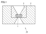
- FIG. 1 is a sectional view of a deformed diamond die 10 according to an embodiment, a diamond 1 forming the deformed diamond die 10, a case 2 containing the diamond 1, and a sintered alloy 3 interposed therebetween.
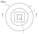
- FIG. 2 is a front view of diamond 1 in FIG.
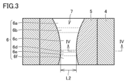
- FIG. 3 is a cross-sectional view taken along line III-III in FIG.
- FIG. 4 is an enlarged cross-sectional view of the bearing portion 6d taken along line IV-IV in FIG.
- FIG. 5 is an enlarged sectional view showing the bearing portion 6d of the machined hole 7 according to the embodiment.
- FIG. 6 is an enlarged sectional view showing the bearing portion 6d of the machined hole 7 according to the embodiment.
- FIG. 1 is a sectional view of a deformed diamond die 10 according to an embodiment, a diamond 1 forming the deformed diamond die 10, a case 2 containing the diamond 1, and a sintered alloy 3 interposed therebetween.
- FIG. 2 is a front view of diamond 1 in FIG.
- FIG. 7 is an enlarged sectional view showing the bearing portion 6d of the machined hole 7 according to the embodiment.
- FIG. 8 is an enlarged sectional view showing the bearing portion 6d of the machined hole 7 according to the embodiment.
- FIG. 9 is an enlarged sectional view showing the bearing portion 6d of the machined hole 7 according to the embodiment.
- FIG. 10 is an enlarged sectional view showing the bearing portion 6d of the machined hole 7 according to the embodiment.
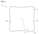
- FIG. 11 is a cross-sectional view of the reduction portion 6c of the machined hole 7 according to the embodiment, and is a cross-sectional view corresponding to FIG.
- FIG. 12 is a cross-sectional view of the machined hole 7 in the drawing direction for explaining the opening angle.
- FIG. 13 is a plan view of machined holes of three diamond dies for explaining the method of manufacturing a deformed wire according to the embodiment.
- FIG. 1 is a sectional view of a deformed diamond die 10 according to an embodiment, a diamond 1 forming the deformed diamond die 10, a case 2 containing the diamond 1, and a sintered alloy 3 interposed therebetween.
- FIG. 1 is a cross-sectional view of a state in which it can be used by being housed in a die case.
- a diamond 1 is housed in a case 2.
- a diamond 1 is attached to the case 2 using a sintered alloy 3 .
- a portion for processing a wire is composed of diamond 1, for example.
- FIG. 2 is a front view of diamond 1 in FIG.
- FIG. 3 is a cross-sectional view taken along line III-III in FIG.
- FIG. 4 is an enlarged cross-sectional view of the bearing portion 6d taken along line IV-IV in FIG.
- diamond 1 comprises a polycrystalline diamond 5 surrounded by a cemented carbide support ring 4 .
- the central portion is composed of a hole inner surface 6 and a processed hole 7 through which the wire to be drawn passes while being in contact with each other.
- the bore inner surface 6 is further subdivided and is shown in detail in FIG.
- the hole inner surface 6 is divided into a bell portion 6a, an approach portion 6b, a reduction portion 6c, a bearing portion 6d, a back relief portion 6e, and an exit portion 6f in order. It has a shape.
- the bearing portion 6d is a region including the portion with the smallest diameter in the machined hole 7. As shown in FIG.
- At least the surface from the bell portion 6a to the bearing portion 6d of the hole inner surface 6 formed by the processed hole 7 is formed as a smooth curved surface in the thickness direction of the diamond. That is, each of the bell portion 6a, the approach portion 6b, the reduction portion 6c, and the bearing portion 6d is formed linearly, and the entirety of each portion is formed with a smooth curved surface, unlike the case where each boundary portion is rounded. be.
- This curved surface is formed by a curved surface of a single R or a curved surface of a compound R, and has a shape in which the boundary between them is not clearly known.
- the wire diameter of the wire after wire drawing with the irregular diamond die 10 is less than 0.1 mm, which is a fine wire diameter.
- the polycrystalline diamond 5 around the processed hole 7 is a single polycrystalline diamond continuous in the circumferential direction of the processed hole 7 . Since the polycrystalline diamond 5 around the machined hole 7 is a single polycrystalline diamond continuous in the circumferential direction of the machined hole, it has a higher strength than a split diamond. As a result, the accuracy of the machined holes is high, and the surface roughness of the wire rod after wire drawing can be reduced.
- the length in the wire drawing direction is 1.0L2.
- the portion with the smallest inner diameter is the center of the bearing portion 6d, and the areas of 0.5L2 above and below that portion in the drawing direction are the bearing portions 6d.
- the length of the bearing portion 6d is longer from the viewpoint of improving the life of the deformed diamond die 10, ie, preventing wear and deformation of the polycrystalline diamond 5.
- a range of 1.0L2 from the upstream end of the bearing portion 6d in the wire drawing direction (a range of more than 0.5L2 and up to 1.5L2 from the center of the bearing portion 6d to the upstream side in the wire drawing direction) is the reduction portion 6c.
- the smooth curved surface reduces the contact area, prevents the supply of lubricant from running out, and stabilizes the wire drawing resistance, so the disconnection prevention effect is extremely large. Furthermore, when the bearing portion 6d is polished, if the length of the bearing portion 6d is long, it is difficult to obtain a smooth surface with small surface roughness. This also has the effect of stabilizing the wire drawing resistance.
- the surface roughness Sa of the bearing portion 6d is, for example, 0.05 ⁇ m or less.
- Surface roughness Sa is defined in ISO 25178.
- the measurement range shall be a range with 20 or more peaks and valleys in the measurement range. Measurement is performed under the conditions that pre-measurement processing is performed, tilt correction is performed, and Gaussian filter is not performed.
- the bearing portion 6d is the portion with the smallest diameter in the machined hole 7, and the surface roughness of the bearing portion 6d is closely related to the surface roughness of the wire. When the surface roughness Sa of the bearing portion 6d exceeds 0.05 ⁇ m, the surface roughness of the wire becomes rough.
- the surface roughness Sa of the bearing portion 6d is more preferably 0.03 ⁇ m or less, most preferably 0.01 ⁇ m or less, in order to obtain a die with high precision and long life. It is preferable that the surface roughness Sa of the bearing portion 6d is as small as possible. However, in terms of industrial production and cost effectiveness, the surface roughness Sa of the bearing portion 6d is preferably 0.002 ⁇ m or more.
- the processed hole 7 of the deformed die was filled with a transfer material (for example, Repliset manufactured by Marumoto Struers Co., Ltd.), and the surface of the processed hole 7 was transferred.
- a transfer material for example, Repliset manufactured by Marumoto Struers Co., Ltd.
- the average value of the surface roughnesses Sa at the three locations is taken as the surface roughness Sa of the bearing portion 6d.
- the surface roughness Sa of the drawn wire is also measured at arbitrary three points by observing the surface with the laser microscope. Let the average value of the surface roughness Sa of the three places be the surface roughness Sa of a wire.
- the surface roughness Sa of the reduction portion 6c is 0.1 ⁇ m or less. If the surface roughness Sa of the reduction portion 6c is 0.1 ⁇ m or less, the surface roughness of the wire rod after wire drawing can be reduced because the surface roughness of the reduction portion 6c upstream of the bearing portion 6d is small.
- the surface roughness Sa of the reduction portion 6c is more preferably 0.05 ⁇ m or less, most preferably 0.03 ⁇ m or less. It is preferable that the surface roughness Sa of the reduction portion 6c is as small as possible. However, in terms of industrial production and cost effectiveness, the surface roughness Sa of the reduction portion 6c is preferably 0.01 ⁇ m or more.
- the surface roughness of the reduction portion 6c is measured in the same manner as the surface roughness of the bearing portion 6d.
- the drawn wire is used for motor windings and the like. In such applications, it is necessary to wind the wire at a high density, so the smaller the R of the corner portion of the wire, the better. Therefore, the square corner portion 7a of the bearing portion has a radius of 20 ⁇ m or less. The smaller the radius of curvature of the corner portion, the better. However, in view of industrial production and cost effectiveness, it is preferable that the radius of the corner portion 7a is 1 ⁇ m or more.
- the machined hole 7 has a quadrangular shape
- the machined hole 7 is not limited to a quadrangle, and may be other polygons such as triangles and hexagons. It is preferable that a straight portion is included in the multi-section orthogonal to the longitudinal direction of the wire.
- the length of the longest side is 100 ⁇ m or less. There is no lower limit to the length of the longest side. However, if the longest side is too short, the manufacturing cost will be high in terms of industrial production. Therefore, considering the cost effectiveness, the length of the longest side is preferably 5 ⁇ m or more.
- the first side 7b1 and the second side 7b2 are arranged to face each other.
- the distance between the first side 7b1 and the second side 7b2 varies depending on the location.
- the maximum distance is L1 and the minimum distance is L2.
- the first side 7b1 and the second side 7b2 are curved so as to protrude toward the center 7c. In this embodiment, all four sides protrude toward the center 7c. It does not have to be convex toward the center 7c.
- 5 to 10 are sectional views showing enlarged bearing portions 6d of machined holes 7 according to the embodiment.
- 5 to 10 show machined holes 7 with different maximum distance L1 and minimum distance L2.
- FIG. 10 shows the shape with the largest value of maximum distance L1/minimum distance L2, and in FIG. 10, maximum distance L1/minimum distance L2 is 150%.
- 5 to 10 show bearing cross sections.
- the wire rod is strongly processed by the straight portion of the processed hole 7 .
- the metal forming the processed wire moves to the corner portion 7a, a sufficient amount of the metal does not move, making it difficult to fill the corner portion 7a with the metal, and the shape of the wire after processing does not become a square.
- the first side 7b1 and the second side 7b2 are formed so as to have the maximum distance L1 at the corner portion 7a. Easy to move. As a result, there is an effect that the shape of the wire after processing tends to be square.
- the deformed diamond die 10 is a deformed die for manufacturing a deformed wire, and is provided with a processing hole 7 having a bearing portion 6d.
- a side 7b1 and a second side 7b2 are provided, and the first side 7b1 and the second side 7b2 have a convex shape toward the center 7c of the processing hole 7 in the cross section.
- the shape of the processed hole 7 is a shape similar to a quadrangle, but it is not limited to this, and may be a track shape in which a straight line and a semicircle are connected. In this case, the linear portion becomes convex toward the center.
- FIG. 11 is a cross-sectional view of the reduction portion 6c of the machined hole 7 according to the embodiment, and is a cross-sectional view corresponding to FIG.
- FIG. 12 is a cross-sectional view of the machined hole 7 in the drawing direction for explaining the opening angle.
- the cross-sectional shape (reduction cross-section) of the reduction portion 6c is substantially similar to the cross-sectional shape of the bearing portion 6d.
- the angle ⁇ formed by the tangent line 6c1 of the wall surface and the center line 7d in the reduction portion 6c is the opening angle (hereinafter referred to as the reduction angle) in the reduction portion 6c.
- the tangent line 6c1 and the reduction portion 6c are in contact with each other at the center position in the drawing direction.
- the reduction angle of the corner portion 7a may be different from the reduction angle of the portions of the first side 7b1 and the second side 7b2.
- the reduction angle of the corner portion 7a may be larger than the reduction angle of the portions of the first side 7b1 and the second side 7b2.
- the reduction angle of the corner portion 7a is made larger than the reduction angle of the portion of the first side 7b1 and the second side 7b2 in this manner, the area reduction rate of the corner portion 7a is reduced to that of the first side 7b1 and the second side 7b2. can be set larger than the area reduction rate of the portion.
- the wire rod to be drawn is more sharply drawn at the corner portion 7a than at the first side 7b1 and the second side 7b2. In this way, even if the corner portion 7a of the ultra-thin wire rod targeted by the deformed die of the present disclosure has a very small R, the wire rod can be easily processed to every corner of the corner portion 7a. This improves the shape accuracy of the drawn wire.
- the resistance during wire drawing increases when the area reduction rate is increased, the increase in resistance during wire drawing is suppressed by shortening the length of the bearing portion 6d or reducing the surface roughness as described above. and the problem of wire breakage is less likely to occur.
- the reduction angle of the corner portion 7a may be set to increase as the distance from the first side 7b1 and the second side 7b2 approaches the tip 7a1 of the corner portion 7a.
- the front end 7a1 of the corner portion 7a refers to a portion of the corner portion 7a that is farthest from the center 7c.
- the front end 7a1 of the corner portion 7a has the largest area reduction rate, and the wire rod can be easily processed up to the front end 7a1 of the corner portion 7a.
- the corner portions 7a can be easily processed, and the accuracy of the corner portions 7a can be easily improved.
- the grain size of the diamond forming the polycrystalline diamond 5 In order to reduce the radius R of the corner portion 7a and to reduce the surface roughness Sa of the bearing portion 6d, the grain size of the diamond forming the polycrystalline diamond 5 must be small. Polycrystalline diamond (sintered diamond) 5 having an average grain size of 500 nm or less is used. Furthermore, the average grain size of diamond is related to the surface roughness of the wire, and if the average grain size of diamond exceeds 500 nm, the surface roughness of the wire becomes rough.
- the average grain size of diamond is more preferably 300 nm or less, and most preferably 100 nm or less.
- the average particle size of diamond is preferably 5 nm or more.
- the polycrystalline diamond 5 is photographed with a scanning electron microscope at three arbitrary locations within a range of 5 ⁇ m ⁇ 5 ⁇ m. Individual diamond grains are extracted from the photographed image, the extracted diamond grains are binarized, and the area of each diamond grain is calculated. A circle having the same area as each diamond particle is assumed, and the diameter of this circle is taken as the diameter of the diamond particle. The arithmetic mean value of each diamond particle size (circle diameter) is taken as the average particle size.
- the polycrystalline diamond 5 may contain a binder.
- the proportion of binder in polycrystalline diamond is preferably 5% by volume or less.
- the ratio of the binder is more preferably 3% by volume or less, and most preferably no binder is contained.
- polycrystalline diamond 5 was examined by scanning electron microscopy at any three locations within a range of 5 ⁇ m ⁇ 5 ⁇ m, as described in the paragraph “(diamond grain size)” above. take pictures. Read the photographed image with Adobe Photoshop, etc., calculate the threshold that matches the original image from the trace of the contour, and convert it to two gradations using that threshold. It is possible to calculate the area of the binder appearing white by this two-gradation. Diamond grains appear gray and grain boundaries appear black. Let the area ratio of the binder be the volume ratio of the binder.
- diamond 1 is used to process a wire rod.
- the bearing portion 6d may be made of a hard material other than the diamond 1 in the deformed die.
- Examples of the material forming the bearing portion 6d include cubic boron nitride (CBN) and cemented carbide.
- the material of the bearing portion 6d can be determined according to the material of the wire to be processed.
- Sintered diamond is prepared as a material for the irregular-shaped diamond die 10 . After processing this sintered diamond into a cylindrical shape, a pilot hole is made by a laser processing method. Next, rough machining is performed by an electric discharge machining method. Next, finishing is performed by lapping. The details of the lapping method are as follows.
- a stainless steel wire having a rectangular cross-sectional shape smaller than the processing hole and rounded at each corner is produced by a rolling method or the like.
- FIG. 13 is a plan view of machined holes of three diamond dies for explaining the method of manufacturing a deformed wire according to the embodiment.
- the wire rod 100 is processed in the processing hole 107 .
- the wire rod 100 is processed into a nearly rectangular shape.
- the second step wire drawing is performed using the processing hole 7.
- the vicinity of the center of the side portion is deformed and processed so as to extend toward the corner portion 7a.
- the shape of the wire rod 100 becomes a shape that tapers toward the corner portion 7a.
- the wire rod 100 is processed through the processing hole 207 of the deformed die for finishing.
- the portion closer to the corner portion 7a than the side portion of the cross section of the wire rod 100 is largely deformed and processed, and the wire rod 100 is also processed into a shape such that the wire rod 100 is in contact with the processing hole 207 even at the small R corner portion 7a. .
- each stage from the first stage to the third stage one or more odd-shaped dies may be used.
- the number of sheets can be increased according to the wire rod system and the size of R of the corner portion 7a.
- Wires to be drawn can be made of various metals such as copper, silver, iron, gold, and aluminum.
- Example 2 The wire drawing was evaluated by combinations 1 to 3 of irregular-shaped dies.
- wire drawing is performed using three odd-shaped dies.
- Material of Diamond Dice The material of the odd-shaped die is common in any of the combinations 1 to 3.
- the deformed die is substantially made of diamond only, and is made of polycrystalline diamond having an average grain size of 50 nm.
- the side of the first odd-shaped die is not provided with a projection directed toward the center of the side, as shown in FIGS. 4 to 11, and the specifications are as follows.
- Reduction angle 16 degrees
- Bearing length 10 ⁇ m
- Bearing surface roughness Sa0.021 ⁇ m
- Distance between facing sides of bearing part 109 ⁇ m
- Corner radius R 30 ⁇ m
- Second die (2-2-1)
- the specifications of the second odd-shaped die in combination 1 are as follows (Fig. 5).
- Reduction angle 15 degrees (same for sides and R)
- Bearing portion 6d length 10 ⁇ m
- Surface roughness of bearing portion 6d Sa 0.025 ⁇ m
- Distance L1 of bearing portion 6d 90 ⁇ m
- Distance L2 of bearing portion 6d 98 ⁇ m
- Radius R of corner portion 7a 10 ⁇ m (2-2-2)
- the specifications of the second odd-shaped die in combination 2 are as follows (Figs. 5 and 11).
- Reduction angle 15 degrees (parts of sides 7b1 and 7b2)
- Reduction angle 15 to 18 degrees (R portion of corner portion 7a).
- the reduction angle is 15 degrees at the boundary between the sides 7b1 and 7b2 and the corner 7a, and the angle gradually increases toward the tip 7a1 until the angle at the tip 7a1 is 18 degrees.
- Reduction angle 17 degrees
- Bearing part length 10 ⁇ m
- Surface roughness of bearing part Sa0.020 ⁇ m
- Distance between facing sides of bearing part 91 ⁇ m Corner radius R: 7 ⁇ m
- Third die In combinations 1 to 3, the sides of the third odd-shaped die are not provided with protrusions directed toward the center on the sides, as shown in FIGS. is as follows.
- Bearing part length 10 ⁇ m
- Surface roughness of bearing part Sa0.018 ⁇ m
- Distance between facing sides of bearing part 80 ⁇ m Corner radius R: 7 ⁇ m
- Wire before drawing The specifications of the wire to be drawn are as follows.
- the size of the corner R is measured by cutting the drawn wire at any three locations and observing the cut cross section with a laser microscope (Keyence Corporation, shape analysis laser microscope, VK-X series) to measure the size of the R. bottom.
- a laser microscope Keyence Corporation, shape analysis laser microscope, VK-X series
- the surface roughness of the wire rod was measured by observing arbitrary three points of the drawn wire rod with a laser microscope (Keyence Corporation, shape analysis laser microscope, VK-X series) and measuring the surface roughness Sa at arbitrary three points.
Landscapes
- Engineering & Computer Science (AREA)
- Mechanical Engineering (AREA)
- Metal Extraction Processes (AREA)
Abstract
Description
従来の異形ダイスを用いて作製された異形線の精度が低いという問題があった。
[本開示の効果]
本開示に従えば、異形線の加工精度を高めることができる。
(全体の構成)
異形線伸線用ダイヤモンドダイスについて図面を用いてその概要を説明する。図1は、実施の形態に従った異形ダイヤモンドダイス10、異形ダイヤモンドダイス10を構成するダイヤモンド1、ダイヤモンド1を収納するケース2およびそれらの間に介在する焼結合金3の断面図である。図1は、ダイスケースに収めて使用できる状態の断面図である。ダイヤモンド1はケース2に収納される。ダイヤモンド1は焼結合金3を用いてケース2に取り付けられている。異形ダイスとしての異形ダイヤモンドダイス10において、線材を加工する部分は、たとえばダイヤモンド1によって構成される。
ベアリング部6dの正面形状が四角形でその四角形の相対する面の距離(第1の辺7b1および第2の辺7b2間の最小距離)をL2とした場合に、伸線方向の長さ1.0L2の範囲をベアリング部6dとする。内径が最も小さい部分がベアリング部6dの中心であり、その部分に対して伸線方向の上下に0.5L2ずつの領域がベアリング部6dである。一般に、ベアリング部6dの長さは、異形ダイヤモンドダイス10の寿命向上すなわち多結晶ダイヤモンド5の摩耗防止や形状変化防止の点からは長い方が好ましい。さらに、ベアリング部6dの伸線方向の上流端から1.0L2の範囲(ベアリング部6dの中心から伸線方向上流側に0.5L2を超え1.5L2までの範囲)がリダクション部6cである。
ベアリング部6dの表面粗さSaがたとえば0.05μm以下である。表面粗さSaは、ISO 25178で定義される。測定範囲は、測定範囲中の山、谷が20山以上ある範囲とする。測定前処理は有り、傾き補正は有り、ガウシアンフィルタは無しの条件で測定する。ベアリング部6dは加工孔7において最も径の小さい部分であり、ベアリング部6dの表面粗さが線材の表面粗さと深く関連する。ベアリング部6dの表面粗さSaが0.05μmを超えると線材の表面粗さが粗くなる。高精度で長寿命のダイスとするには、ベアリング部6dの表面粗さSaが0.03μm以下であることがより好ましく、0.01μm以下であることが最も好ましい。ベアリング部6dの表面粗さSaは小さければ小さいほど好ましい。ただし、工業生産上、費用対効果を考慮すれば、ベアリング部6dの表面粗さSaは0.002μm以上であることが好ましい。
好ましくは、リダクション部6cの表面粗さSaは0.1μm以下である。リダクション部6cの表面粗さSaが0.1μm以下であれば、ベアリング部6d上流のリダクション部6cの表面粗さが小さいため、伸線後の線材の表面粗さを小さくすることができる。
伸線された線材は、モータの巻線などに使用する。このような用途では、高密度に巻く必要があるため、線材のコーナー部のRは小さいほど好ましい。そのため、ベアリング部の四角形のコーナー部7aのRは、20μm以下としている。コーナー部のRは小さければ小さいほど好ましい。ただし、工業生産上、費用対効果を考慮すれば、コーナー部7aのRは1μm以上であることが好ましい。
図11は、実施の形態に従った加工孔7のリダクション部6cの断面図であって、図5に対応する断面図である。図12は開き角度を説明するために示す加工孔7の伸線方向の断面図である。本開示において、図11に示すように、リダクション部6cにおける断面形状(リダクション断面)は、ベアリング部6dにおける断面形状とほぼ相似形である。リダクション部6cにおいて壁面の接線6c1と中心線7dとのなす角度θがリダクション部6cにおける開き角度(以下、リダクション角度という)である。リダクション部6cにおいて伸線方向の中心位置において接線6c1とリダクション部6cとが接触する。
コーナー部7aのRを小さくするため、さらにベアリング部6dの表面粗さSaを小さくするためには、多結晶ダイヤモンド5を構成するダイヤモンドの粒径が小さくなければならない。ダイヤモンドの平均粒径が500nm以下の多結晶ダイヤモンド(焼結ダイヤモンド)5を用いる。さらに、ダイヤモンドの平均粒径は線材の表面粗さとも関係し、ダイヤモンドの平均粒径が500nmを超えると、線材の表面粗さが粗くなる。
多結晶ダイヤモンド5には、バインダが含まれていてもよい。多結晶ダイヤモンドにおけるバインダの割合は5体積%以下であることが好ましい。高精度で長寿命のダイスとするには、バインダの割合は、3体積%以下であることがより好ましく、バインダが含まれないのが最も好ましい。
上記の例においては、ダイヤモンド1により線材を加工する例を示した。しかしながら、異形ダイスにおいてダイヤモンド1以外の硬質材料によってベアリング部6dが構成されていてもよい。
異形ダイヤモンドダイス10の材料として、焼結ダイヤモンドを準備する。この焼結ダイヤモンドを円柱形状に加工した後、レーザー加工法によって下穴を開ける。次に、放電加工法によって粗加工を行う。次に、ラッピング加工により、仕上げ加工を行う。ラッピング加工法の詳細は以下の通りである。
図13は、実施の形態に従った異形線の製作方法を説明するために示す3枚のダイヤモンドダイスの加工孔の平面図である。
異形ダイスの組み合わせ1から3により伸線の評価を行った。
(1)ダイヤモンドダイスの素材
組み合わせ1から3のいずれであっても、異形ダイスの素材は共通である。異形ダイスは実質的にダイヤモンドのみからなり、ダイヤモンドの平均粒径が50nmの多結晶ダイヤモンドからなる。
組み合わせ1から3において、1枚目から3枚目の異形ダイスは以下の諸元を有する。
組み合わせ1から3において1枚目の異形ダイスは共通である。
リダクション角度:16度
ベアリング長さ:10μm
ベアリング表面あらさ:Sa0.021μm
ベアリング部の辺の対向する距離:109μm
コーナー部の半径R:30μm
(2-2)2枚目
(2-2-1)組み合わせ1において2枚目の異形ダイスの諸元は以下の通りである(図5)。
リダクション角度:15度(辺の部分、Rの部分とも同じ)
ベアリング部6d長さ:10μm
ベアリング部6d表面あらさ:Sa0.025μm
ベアリング部6dの距離L1:90μm
ベアリング部6dの距離L2:98μm
コーナー部7aの半径R:10μm
(2-2-2)組み合わせ2において2枚目の異形ダイスの諸元は以下の通りである(図5,11)。
リダクション角度:15度(辺7b1,7b2の部分)
リダクション角度:15~18度(コーナー部7aのRの部分)。リダクション角度は辺7b1,7b2とコーナー部7aの境界部が15度で、先端7a1に向かい、徐々に角度が大きくなり、先端7a1の角度が18度
ベアリング部6dの長さ:10μm
ベアリング部6dの表面あらさ:Sa0.025μm
ベアリング部6dの距離L1:90μm
ベアリング部6dの距離L2:98μm
コーナー部7aの半径R:10μm
(2-2-3)組み合わせ3において、2枚目の異形ダイスの辺には、図4から11で示すような、辺において中心に向かう凸部が設けられておらず、諸元は、以下の通りである。
リダクション角度:17度
ベアリング部の長さ:10μm
ベアリング部の表面あらさ:Sa0.020μm
ベアリング部の辺の対向する距離:91μm
コーナー部の半径R:7μm
(2-3)3枚目
組み合わせ1から3において、3枚目の異形ダイスの辺には、図4から11で示すような、辺において中心に向かう凸部が設けられておらず、諸元は、以下の通りである。
リダクション角度:16度
ベアリング部の長さ:10μm
ベアリング部の表面あらさ:Sa0.018μm
ベアリング部の辺の対向する距離:80μm
コーナー部の半径R:7μm
(3)伸線加工前の線材
伸線加工する線材の仕様は以下である。
線径(伸線前):Φ130μm
(4)伸線加工後の線材
伸線加工した後の線材の状態は以下のようであった。
(4-1-1)線径
測定点1から3における線径は以下の通りである。
測定点1…縦80.1μm、横80.0μm
測定点2…縦80.0μm、横80.2μm
測定点3…縦80.2μm、横80.1μm
平均値…80.1μm
(4-1-2)伸線時の抵抗の大きさ:1.7N
(4-1-3)コーナRの大きさ:R7μm
(4-1-4)線材の表面あらさ
測定点1…Sa0.030μm
測定点2…Sa0.033μm
測定点3…Sa0.035μm
平均値…Sa0.033μm
(4-2)組み合わせ2
(4-2-1)線径
測定点1…縦79.8μm、横80.1μm
測定点2…縦79.9μm、横79.8μm
測定点3…縦80.1μm、横79.9μm
平均値…79.9μm
(4-2-2)伸線時の抵抗の大きさ:1.75N
(4-2-3)コーナRの大きさ:R7μm
(4-2-4)線材の表面あらさ
測定点1…Sa0.033μm
測定点2…Sa0.027μm
測定点3…Sa0.032μm
平均値…Sa0.031μm
(4-3)組み合わせ3
(4-3-1)線径
測定点1…縦79.6μm、横79.8μm
測定点2…縦79.6μm、横79.5μm
測定点3…縦79.8μm、横79.6μm
平均値…79.7μm
(4-3-2)伸線時の抵抗の大きさ:2.0N
(4-3-3)コーナRの大きさ:R12μm
(4-3-4)線材の表面あらさ
測定点1…Sa0.026μm
測定点2…Sa0.036μm
測定点3…Sa0.034μm
平均値…Sa0.032μm
(5)伸線加工した線材の測定方法
線径は、伸線した線材の任意の3点(測定点1から3)の縦・横の寸法を、電子マイクロメータで測定した。
これらの測定結果から、組み合わせ2において最もよい結果が得られた。次に組み合わせ1においてよい結果が得られた。組み合わせ3は従来品であるため、組み合わせ1および2よりも線材の品質が低いことが分かる。
Claims (7)
- 異形線を製作するための異形ダイスであって、
ベアリング部を有する加工孔が設けられており、
伸線方向に垂直な前記ベアリング部のベアリング断面において、互いに向かい合う第1の辺および第2の辺が設けられており、
前記第1の辺および前記第2の辺は前記ベアリング断面における前記加工孔の中心側に凸の形状を有する、異形ダイス。 - 前記第1の辺および前記第2の辺間の最大距離は最小距離の100%を超え150%以下である、請求項1に記載の異形ダイス。
- 前記ベアリング部の伸線方向の上流にリダクション部が設けられており、伸線方向に垂直な前記リダクション部のリダクション断面および前記ベアリング断面において、前記第1の辺および前記第2の辺が設けられており、前記リダクション断面において前記第1の辺および前記第2の辺の端部に前記加工孔のコーナー部が設けられており、前記コーナー部のリダクションの開き角度は、前記第1の辺および前記第2の辺の部分のリダクションの開き角度とは異なる角度である、請求項1または2に記載の異形ダイス。
- 前記コーナー部のリダクションの開き角度は、前記第1の辺および前記第2の辺の部分のリダクションの開き角度よりも大きい角度である、請求項3に記載の異形ダイス。
- 前記コーナー部のリダクションの開き角度は、前記第1の辺および前記第2の辺から遠ざかり前記コーナー部の先端に近づくほど大きい角度である、請求項4に記載の異形ダイス。
- 異形線を製作する方法であって、第1の異形ダイス、請求項1または2に記載の異形ダイス、および第2の異形ダイスの順に線材を加工する、異形線を製作する方法。
- 異形線を製作する方法であって、第1の異形ダイス、請求項3に記載の異形ダイス、および第2の異形ダイスの順に線材を加工する、異形線を製作する方法。
Priority Applications (4)
| Application Number | Priority Date | Filing Date | Title |
|---|---|---|---|
| US18/703,315 US20250235923A1 (en) | 2021-11-11 | 2022-11-08 | Irregularly-shaped die and method for producing irregularly-shaped wire |
| JP2023559640A JP7621507B2 (ja) | 2021-11-11 | 2022-11-08 | 異形ダイスおよび異形線を製作する方法 |
| CN202280074991.0A CN118234575A (zh) | 2021-11-11 | 2022-11-08 | 异形模具以及制作异形线的方法 |
| EP22892766.1A EP4431198A4 (en) | 2021-11-11 | 2022-11-08 | Irregularly Shaped Die and Method for Manufacturing an Irregularly Shaped Die Line |
Applications Claiming Priority (2)
| Application Number | Priority Date | Filing Date | Title |
|---|---|---|---|
| JP2021184040 | 2021-11-11 | ||
| JP2021-184040 | 2021-11-11 |
Publications (1)
| Publication Number | Publication Date |
|---|---|
| WO2023085268A1 true WO2023085268A1 (ja) | 2023-05-19 |
Family
ID=86335744
Family Applications (1)
| Application Number | Title | Priority Date | Filing Date |
|---|---|---|---|
| PCT/JP2022/041556 Ceased WO2023085268A1 (ja) | 2021-11-11 | 2022-11-08 | 異形ダイスおよび異形線を製作する方法 |
Country Status (5)
| Country | Link |
|---|---|
| US (1) | US20250235923A1 (ja) |
| EP (1) | EP4431198A4 (ja) |
| JP (1) | JP7621507B2 (ja) |
| CN (1) | CN118234575A (ja) |
| WO (1) | WO2023085268A1 (ja) |
Cited By (2)
| Publication number | Priority date | Publication date | Assignee | Title |
|---|---|---|---|---|
| JP7691586B1 (ja) * | 2024-01-29 | 2025-06-11 | 株式会社アライドマテリアル | 異形ダイス |
| WO2025164531A1 (ja) * | 2024-01-29 | 2025-08-07 | 株式会社アライドマテリアル | 異形ダイス |
Citations (6)
| Publication number | Priority date | Publication date | Assignee | Title |
|---|---|---|---|---|
| JPS57156215U (ja) * | 1981-03-25 | 1982-10-01 | ||
| JP2002263727A (ja) * | 2001-03-05 | 2002-09-17 | Nippon Steel Corp | 軌道レールの製造装置および軌道レールの製造方法 |
| JP2005254311A (ja) * | 2004-03-15 | 2005-09-22 | Allied Material Corp | 異形線伸線用ダイヤモンドダイス |
| JP2008149324A (ja) * | 2006-12-13 | 2008-07-03 | Sanyo Metal Co Ltd | 異形金属材料の引抜き工法 |
| WO2018123513A1 (ja) | 2016-12-26 | 2018-07-05 | 株式会社アライドマテリアル | 異形ダイヤモンドダイス |
| JP2021184040A (ja) | 2020-05-22 | 2021-12-02 | 株式会社タツミ楽器 | 減音作用を有するマウスピース |
Family Cites Families (3)
| Publication number | Priority date | Publication date | Assignee | Title |
|---|---|---|---|---|
| US2846056A (en) * | 1953-05-26 | 1958-08-05 | Patents And Invest Ltd | Drawing dies |
| JP2020199531A (ja) * | 2019-06-11 | 2020-12-17 | 愛知製鋼株式会社 | 引抜ダイス、引抜加工方法、および引抜ダイスの設計方法 |
| KR102250707B1 (ko) * | 2020-12-11 | 2021-05-11 | 송기수 | 직사각형 가공 소재 인발용 인발 다이 |
-
2022
- 2022-11-08 WO PCT/JP2022/041556 patent/WO2023085268A1/ja not_active Ceased
- 2022-11-08 EP EP22892766.1A patent/EP4431198A4/en active Pending
- 2022-11-08 JP JP2023559640A patent/JP7621507B2/ja active Active
- 2022-11-08 CN CN202280074991.0A patent/CN118234575A/zh active Pending
- 2022-11-08 US US18/703,315 patent/US20250235923A1/en active Pending
Patent Citations (6)
| Publication number | Priority date | Publication date | Assignee | Title |
|---|---|---|---|---|
| JPS57156215U (ja) * | 1981-03-25 | 1982-10-01 | ||
| JP2002263727A (ja) * | 2001-03-05 | 2002-09-17 | Nippon Steel Corp | 軌道レールの製造装置および軌道レールの製造方法 |
| JP2005254311A (ja) * | 2004-03-15 | 2005-09-22 | Allied Material Corp | 異形線伸線用ダイヤモンドダイス |
| JP2008149324A (ja) * | 2006-12-13 | 2008-07-03 | Sanyo Metal Co Ltd | 異形金属材料の引抜き工法 |
| WO2018123513A1 (ja) | 2016-12-26 | 2018-07-05 | 株式会社アライドマテリアル | 異形ダイヤモンドダイス |
| JP2021184040A (ja) | 2020-05-22 | 2021-12-02 | 株式会社タツミ楽器 | 減音作用を有するマウスピース |
Non-Patent Citations (1)
| Title |
|---|
| See also references of EP4431198A4 |
Cited By (2)
| Publication number | Priority date | Publication date | Assignee | Title |
|---|---|---|---|---|
| JP7691586B1 (ja) * | 2024-01-29 | 2025-06-11 | 株式会社アライドマテリアル | 異形ダイス |
| WO2025164531A1 (ja) * | 2024-01-29 | 2025-08-07 | 株式会社アライドマテリアル | 異形ダイス |
Also Published As
| Publication number | Publication date |
|---|---|
| CN118234575A (zh) | 2024-06-21 |
| US20250235923A1 (en) | 2025-07-24 |
| JPWO2023085268A1 (ja) | 2023-05-19 |
| EP4431198A4 (en) | 2025-11-12 |
| JP7621507B2 (ja) | 2025-01-24 |
| EP4431198A1 (en) | 2024-09-18 |
Similar Documents
| Publication | Publication Date | Title |
|---|---|---|
| JP7621507B2 (ja) | 異形ダイスおよび異形線を製作する方法 | |
| KR101026648B1 (ko) | 심공 가공용 소경 드릴 및 미세 심공 가공 방법 | |
| JP6805270B2 (ja) | 異形ダイヤモンドダイス | |
| CN101547757A (zh) | 金刚石拉丝模以及使用其进行的线材的制造方法 | |
| JP3352279B2 (ja) | スパイラルエンドミルおよびその製造方法 | |
| CN1942277A (zh) | 球头立铣刀 | |
| JP2016112678A (ja) | ダイヤモンド焼結体ボールエンドミルとその製造方法 | |
| WO2020090372A1 (ja) | 回転工具 | |
| Gao et al. | Generation method and antifriction performance evaluation of discrete micro-pit surface texture based on high speed ball-end milling process | |
| Li et al. | Design of micro square endmills for hard milling applications | |
| JP7634722B2 (ja) | 異形ダイス | |
| KR101062584B1 (ko) | 관의 드로잉 가공용 플러그 및 이것을 이용한 관의 제조 방법 | |
| EP4169643A1 (en) | Tool and tool production method | |
| JP3840661B2 (ja) | ボールエンドミル | |
| US20090245948A1 (en) | Cutting tool | |
| JP7691586B1 (ja) | 異形ダイス | |
| JP7630050B1 (ja) | 伸線ダイス | |
| JP7678835B2 (ja) | 回転切削工具 | |
| JP7764435B2 (ja) | ボールエンドミル | |
| Davidson | Microfinishing and surface textures | |
| WO2025164531A1 (ja) | 異形ダイス | |
| US20220288728A1 (en) | Method of surface texturing for a writing instrument tip | |
| JPH0615348A (ja) | 超硬ダイス | |
| JP2005014202A (ja) | 多刃ボールエンドミル | |
| JP2007269090A (ja) | ハブユニット及びハブユニットの製造方法 |
Legal Events
| Date | Code | Title | Description |
|---|---|---|---|
| 121 | Ep: the epo has been informed by wipo that ep was designated in this application |
Ref document number: 22892766 Country of ref document: EP Kind code of ref document: A1 |
|
| WWE | Wipo information: entry into national phase |
Ref document number: 2023559640 Country of ref document: JP |
|
| WWE | Wipo information: entry into national phase |
Ref document number: 18703315 Country of ref document: US |
|
| WWE | Wipo information: entry into national phase |
Ref document number: 2401002984 Country of ref document: TH |
|
| WWE | Wipo information: entry into national phase |
Ref document number: 202280074991.0 Country of ref document: CN |
|
| WWE | Wipo information: entry into national phase |
Ref document number: 202417043316 Country of ref document: IN |
|
| WWE | Wipo information: entry into national phase |
Ref document number: 2022892766 Country of ref document: EP |
|
| NENP | Non-entry into the national phase |
Ref country code: DE |
|
| ENP | Entry into the national phase |
Ref document number: 2022892766 Country of ref document: EP Effective date: 20240611 |
|
| WWP | Wipo information: published in national office |
Ref document number: 18703315 Country of ref document: US |