WO2023089763A1 - エアロゾル生成装置の回路ユニット、エアロゾル生成装置及びプログラム - Google Patents
エアロゾル生成装置の回路ユニット、エアロゾル生成装置及びプログラム Download PDFInfo
- Publication number
- WO2023089763A1 WO2023089763A1 PCT/JP2021/042555 JP2021042555W WO2023089763A1 WO 2023089763 A1 WO2023089763 A1 WO 2023089763A1 JP 2021042555 W JP2021042555 W JP 2021042555W WO 2023089763 A1 WO2023089763 A1 WO 2023089763A1
- Authority
- WO
- WIPO (PCT)
- Prior art keywords
- time
- aerosol
- control
- puff
- load
- Prior art date
- Legal status (The legal status is an assumption and is not a legal conclusion. Google has not performed a legal analysis and makes no representation as to the accuracy of the status listed.)
- Ceased
Links
Images















Classifications
-
- A—HUMAN NECESSITIES
- A24—TOBACCO; CIGARS; CIGARETTES; SIMULATED SMOKING DEVICES; SMOKERS' REQUISITES
- A24F—SMOKERS' REQUISITES; MATCH BOXES; SIMULATED SMOKING DEVICES
- A24F40/00—Electrically operated smoking devices; Component parts thereof; Manufacture thereof; Maintenance or testing thereof; Charging means specially adapted therefor
- A24F40/50—Control or monitoring
- A24F40/53—Monitoring, e.g. fault detection
-
- A—HUMAN NECESSITIES
- A24—TOBACCO; CIGARS; CIGARETTES; SIMULATED SMOKING DEVICES; SMOKERS' REQUISITES
- A24F—SMOKERS' REQUISITES; MATCH BOXES; SIMULATED SMOKING DEVICES
- A24F40/00—Electrically operated smoking devices; Component parts thereof; Manufacture thereof; Maintenance or testing thereof; Charging means specially adapted therefor
- A24F40/20—Devices using solid inhalable precursors
-
- A—HUMAN NECESSITIES
- A24—TOBACCO; CIGARS; CIGARETTES; SIMULATED SMOKING DEVICES; SMOKERS' REQUISITES
- A24F—SMOKERS' REQUISITES; MATCH BOXES; SIMULATED SMOKING DEVICES
- A24F40/00—Electrically operated smoking devices; Component parts thereof; Manufacture thereof; Maintenance or testing thereof; Charging means specially adapted therefor
- A24F40/50—Control or monitoring
-
- A—HUMAN NECESSITIES
- A24—TOBACCO; CIGARS; CIGARETTES; SIMULATED SMOKING DEVICES; SMOKERS' REQUISITES
- A24F—SMOKERS' REQUISITES; MATCH BOXES; SIMULATED SMOKING DEVICES
- A24F40/00—Electrically operated smoking devices; Component parts thereof; Manufacture thereof; Maintenance or testing thereof; Charging means specially adapted therefor
- A24F40/50—Control or monitoring
- A24F40/51—Arrangement of sensors
-
- A—HUMAN NECESSITIES
- A24—TOBACCO; CIGARS; CIGARETTES; SIMULATED SMOKING DEVICES; SMOKERS' REQUISITES
- A24F—SMOKERS' REQUISITES; MATCH BOXES; SIMULATED SMOKING DEVICES
- A24F40/00—Electrically operated smoking devices; Component parts thereof; Manufacture thereof; Maintenance or testing thereof; Charging means specially adapted therefor
- A24F40/50—Control or monitoring
- A24F40/57—Temperature control
-
- A—HUMAN NECESSITIES
- A24—TOBACCO; CIGARS; CIGARETTES; SIMULATED SMOKING DEVICES; SMOKERS' REQUISITES
- A24F—SMOKERS' REQUISITES; MATCH BOXES; SIMULATED SMOKING DEVICES
- A24F47/00—Smokers' requisites not otherwise provided for
-
- H—ELECTRICITY
- H05—ELECTRIC TECHNIQUES NOT OTHERWISE PROVIDED FOR
- H05B—ELECTRIC HEATING; ELECTRIC LIGHT SOURCES NOT OTHERWISE PROVIDED FOR; CIRCUIT ARRANGEMENTS FOR ELECTRIC LIGHT SOURCES, IN GENERAL
- H05B1/00—Details of electric heating devices
- H05B1/02—Automatic switching arrangements specially adapted to apparatus ; Control of heating devices
- H05B1/0227—Applications
-
- H—ELECTRICITY
- H05—ELECTRIC TECHNIQUES NOT OTHERWISE PROVIDED FOR
- H05B—ELECTRIC HEATING; ELECTRIC LIGHT SOURCES NOT OTHERWISE PROVIDED FOR; CIRCUIT ARRANGEMENTS FOR ELECTRIC LIGHT SOURCES, IN GENERAL
- H05B1/00—Details of electric heating devices
- H05B1/02—Automatic switching arrangements specially adapted to apparatus ; Control of heating devices
- H05B1/0227—Applications
- H05B1/0252—Domestic applications
Definitions
- the present invention relates to a circuit unit of an aerosol generator, an aerosol generator, and a program.
- aerosol generators that generate aerosol by heating a liquid containing fragrance
- the heater is energized when the user's inhalation action is detected, and the liquid inside the glass fiber called a wick is atomized (aerosolized). be done.
- an aerosol is generated when the temperature of the liquid in the weck reaches its boiling point.
- Some recent aerosol generators are provided with a function of preliminarily heating the liquid temperature at the start of suction by energizing the heater even during non-suction.
- This function is called “preheating” in the sense of distinguishing from heating accompanied by generation of aerosol (hereinafter referred to as “main heating”).
- Preheating does not heat to the temperature at which aerosols are generated.
- the preheating function is activated, the liquid temperature at the start of suction is higher than when preheating is not used, so the power supplied to the heater can be efficiently used to generate aerosol. Therefore, it is possible to generate a high-concentration aerosol from the start of suction.
- the supply of liquid to the wick relies on capillary effects.
- the present invention is a technique for suppressing liquid depletion during suction regardless of how the user uses the aerosol generating device when performing the second control that does not generate aerosol prior to the first control that generates aerosol. I will provide a.
- the invention according to claim 1 has a control unit that controls supply of electric power to a load that heats an aerosol source, and the control unit heats the load to a first temperature at which the aerosol is generated. Before the control of, when performing the second control of heating the load to a second temperature lower than the first temperature, when the interval between aerosol suctions is shorter than the first period and a circuit unit of an aerosol generating device that controls at least one of the amount of power supplied to the load in the first control and the amount of power supplied to the load in the second control to be lower than a reference value.
- the invention according to claim 2 further includes a first sensor that detects the inhalation of the aerosol by the user, and the controller controls the current inhalation start from the end of the previous inhalation detected by the first sensor. is shorter than the first period, at least one of the time during which power is supplied to the load in the first control and the time during which power is supplied to the load in the second control is set to the first period.
- the control unit controls the above-described 2.
- the invention according to claim 4 further includes a first sensor for detecting inhalation of aerosol by the user, and the control unit controls the first sensor from the end of heating immediately before the end of generation of aerosol from the aerosol source. If the time until the current suction start detected by the sensor is shorter than the first period, the time to supply power to the load in the first control and the power to the load in the second control 2.
- the invention according to claim 5 has an operation unit that receives a user's operation related to supply and stop of power supply to the load, and the control unit is configured to stop the supply of power immediately before according to the user's operation on the operation unit.
- the circuit unit of an aerosol generating device according to claim 1, wherein at least one is shorter than the second period.
- the invention according to claim 6 further comprises a first sensor for detecting inhalation of the aerosol by the user and a second sensor for detecting the temperature of the load, wherein the control unit detects the temperature of the first sensor. If the temperature detected by the second sensor at the start of suction of the aerosol detected in is higher than the first temperature reference, the time to supply power to the load in the first control and the second control 2.
- the circuit unit of an aerosol generating device wherein at least one of the times during which the load is supplied with power in is shorter than the second period.
- the invention according to claim 7 further includes a first sensor that detects the inhalation of aerosol by the user, and the control unit detects the resistance of the load at the start of inhalation of the aerosol detected by the first sensor. When the value is higher than the first resistance value, at least one of the time during which power is supplied to the load in the first control and the time during which power is supplied to the load in the second control is set longer than the second period.
- a circuit unit of an aerosol generating device for shortening.
- the invention according to claim 8 further comprises a first sensor for detecting inhalation of the aerosol by the user and a third sensor for detecting the temperature of the aerosol source, wherein the control unit detects the temperature of the first sensor If the temperature detected by the third sensor at the start of suction of the aerosol detected in is higher than the second temperature reference, the time to supply power to the load in the first control and the second control in the 2.
- the circuit unit of an aerosol generating device according to claim 1, wherein at least one of the times during which the load is powered is shorter than the second period.
- the control unit predicts the next interval based on the tendency of the past plural times of intervals between suctions of the aerosol, and the predicted interval is shorter than the first period.
- At least one of the power supply time to the load in the first control and the power supply time to the load in the second control of the next suction time is set shorter than the second period,
- a circuit unit of the aerosol generating device according to claim 1.
- the control unit obtains a plurality of past measured values of intervals between aerosol inhalations, and the number of consecutive occurrences of measured values shorter than the first period is the first. When the number of times exceeds 1, the time of power supply to the load in the first control and the time of power supply to the load in the second control in the next and subsequent suction times as the number of times increases. 2.
- the control unit includes it in the calculation of the number of times.
- the control unit controls the amount of electric power supplied to the load in the first control and the The circuit unit of the aerosol generator according to any one of claims 1 to 8, wherein at least one of the amount of electric power supplied to the load is controlled to be small in the second control.
- the invention according to claim 14 further includes a second sensor that detects the temperature of the load, and the control unit detects that the temperature detected by the second sensor during the period of the first control is The circuit unit of an aerosol generating device according to any one of the preceding claims, wherein the heating of the load is forced to end at that point if a third temperature criterion is reached.
- the invention according to claim 15 further includes a third sensor that detects the temperature of the aerosol source, and the controller controls the temperature detected by the third sensor during the period of the first control.
- the circuit unit of an aerosol generating device according to any one of the preceding claims, wherein the heating of the load is forced to end at that point if a fourth temperature criterion is reached.
- the controller controls the first maximum voltage to be supplied to the load to generate the aerosol when the interval between suctions of the aerosol is shorter than the first period. value is controlled to a value smaller than the second maximum voltage value supplied to the load when the interval between aerosol inhalations is longer than the first period. or a circuit unit of the aerosol generator according to item 1.
- the invention according to claim 17 has a control unit for controlling supply of electric power to a load that heats an aerosol source, and the control unit heats the load to a first temperature at which the aerosol is generated.
- the control unit heats the load to a first temperature at which the aerosol is generated.
- a computer for controlling power supply to a load that heats an aerosol source is provided with the first
- the first control for heating the load to a second temperature lower than the first temperature, if the interval between aerosol inhalations is shorter than the first period, in the first control
- Liquid drying can be suppressed.
- the second aspect of the invention when performing the second control, it is possible to suppress liquid drying even when the user's suction interval is short.
- the third aspect of the invention when performing the second control, it is possible to suppress liquid drying even when the user's suction interval is short.
- the fourth aspect of the present invention when the second control is performed, even if the user's suction interval is short, it is possible to suppress liquid drying.
- the second control when the second control is performed, even if the user's suction interval is short, it is possible to suppress liquid drying.
- the second control when the second control is performed, even if the user's suction interval is short, it is possible to suppress the liquid drying up.
- the second control when the second control is performed, even if the user's suction interval is short, it is possible to suppress liquid drying.
- the eighth aspect of the invention even when the user's suction interval is short when performing the second control, it is possible to suppress liquid drying.
- the control for preventing liquid drying can be performed.
- the control for preventing liquid drying when the second control is performed and it is confirmed that the user's suction interval tends to be short, the control for preventing liquid drying can be performed.
- the control for preventing the liquid from drying up can be executed.
- the second control when the second control is performed, even if the user's suction interval is short, it is possible to suppress liquid drying.
- the second control when the second control is performed, even if the user's suction interval is short, it is possible to suppress liquid drying.
- the fourteenth aspect of the invention it is possible to suppress liquid drying even when an environment in which liquid drying is likely to occur is detected when performing the second control.
- the fifteenth aspect of the present invention it is possible to suppress liquid drying even when an environment in which liquid drying is likely to occur is detected when performing the second control.
- the sixteenth aspect of the invention even when the user's suction interval is short when performing the second control, it is possible to suppress liquid drying.
- the seventeenth aspect of the invention it is possible to suppress drying up of liquid during suction regardless of how the user uses the aerosol generating device when the second control is performed.
- the eighteenth aspect of the invention it is possible to suppress drying up of the liquid during suction regardless of how the user uses the aerosol generating device when performing the second control.
- FIG. 1 is a diagram for explaining an example of the external configuration of an aerosol generating device assumed in Embodiment 1;
- FIG. 1 is a diagram schematically showing the internal configuration of an aerosol generator assumed in Embodiment 1.
- FIG. It is a figure explaining preheating time and main heating time.
- (A) shows the arrangement of the preheating time and the main heating time, and
- (B) shows the temperature change of the aerosol source.
- 4 is a flowchart for explaining an example of control of main heating time by a control unit used in Embodiment 1.
- FIG. FIG. 10 is a diagram illustrating an example of setting the main heating time depending on the presence or absence of preheating and the length of the puff interval.
- FIG. (A) shows a setting example of the main heating time without preheating
- (B) shows a setting example of the main heating time with preheating
- 4 is a diagram for explaining the relationship between the puff interval and the setting of the main heating time in Embodiment 1.
- FIG. (A) shows an example of suction timing
- (B) shows an example of setting the main heating time without preheating
- (C) shows an example of setting the main heating time with preheating.
- 9 is a flowchart for explaining an example of control of main heating time by a control unit used in Embodiment 2.
- FIG. 10 is a diagram for explaining the relationship between the puff interval and the setting of the main heating time in Embodiment 2; (A) shows an example of suction timing, (B) shows an example of setting the main heating time without preheating, and (C) shows an example of setting the main heating time with preheating.
- 10 is a flowchart for explaining an example of control of main heating time by a control unit used in Embodiment 3.
- FIG. FIG. 11 is a diagram for explaining the relationship between the puff interval and the setting of the main heating time in Embodiment 3; (A) shows an example of suction timing, (B) shows an example of setting the main heating time without preheating, and (C) shows an example of setting the main heating time with preheating.
- FIG. 12 is a flowchart for explaining an example of control of main heating time by a control unit used in Embodiment 4.
- FIG. FIG. 13 is a diagram for explaining the relationship between the puff interval and the setting of the main heating time in Embodiment 4; (A) shows an example of suction timing, (B) shows an example of setting the main heating time without preheating, and (C) shows an example of setting the main heating time with preheating.
- FIG. 10 is a diagram schematically showing the internal configuration of an aerosol generating device assumed in Embodiment 5; 14 is a flowchart for explaining an example of control of main heating time by a control unit used in Embodiment 5.
- FIG. 12 is a diagram for explaining the relationship between the puff interval and the setting of the main heating time in Embodiment 5.
- FIG. (A) shows an example of the timing of suction
- (B) shows the temperature change of the heating part without preheating
- (C) shows an example of setting the main heating time without preheating
- (D ) shows the temperature change of the heating part with preheating
- (E) shows a setting example of the main heating time with preheating.
- FIG. 12 is a diagram schematically showing the internal configuration of an aerosol generating device assumed in Embodiment 6
- 14 is a flowchart for explaining an example of control of main heating time by a control unit used in Embodiment 6.
- FIG. 14 is a diagram for explaining the relationship between the puff interval and the setting of the main heating time in Embodiment 6.
- FIG. (A) shows an example of suction timing
- (B) shows a change in the resistance value of the heating part without preheating
- (C) shows an example of setting the main heating time without preheating
- (D) shows a change in the resistance value of the heating portion with preheating
- (E) shows an example of setting the main heating time with preheating.
- FIG. 12 is a diagram schematically showing the internal configuration of an aerosol generating device assumed in Embodiment 7;
- FIG. 12 is a flowchart for explaining an example of control of main heating time by a control unit used in Embodiment 7;
- FIG. 14 is a diagram for explaining the relationship between the puff interval and the setting of the main heating time in Embodiment 7.
- FIG. (A) shows an example of suction timing
- (B) shows a change in the temperature of the liquid induction part without preheating
- (C) shows an example of setting the main heating time without preheating
- (D) shows the change in the temperature of the liquid guide section with preheating
- (E) shows an example of setting the main heating time with preheating.
- FIG. 20 is a diagram schematically showing the internal configuration of an aerosol generating device assumed in Embodiment 8
- FIG. 13 is a flowchart for explaining an example of control of main heating time by a control unit used in Embodiment 8.
- FIG. 20 is a diagram for explaining the relationship between the puff interval and the setting of the main heating time in Embodiment 8.
- FIG. (A) shows an example of suction timing
- (B) shows changes in ambient temperature
- (C) shows an example of setting the main heating time without preheating
- (D) shows an example of setting with preheating.
- An example of the setting of the main heating time is shown.
- FIG. 20 is a flowchart for explaining an example of control of main heating time by a control unit used in Embodiment 9.
- FIG. FIG. 22 is a diagram for explaining the relationship between the puff interval and the setting of the main heating time in Embodiment 9.
- FIG. 20 is a flowchart for explaining an example of control of main heating time by a control unit used in Embodiment 10.
- FIG. 22 is a diagram for explaining the relationship between the puff interval and the setting of the main heating time in Embodiment 10.
- FIG. 13 is a flow chart for explaining an example of control of the main heating time by a control unit used in Embodiment 11;
- FIG. 22 is a flowchart for explaining an example of control of the main heating time by a control unit used in Embodiment 12;
- FIG. 20 is a diagram schematically showing the internal configuration of an aerosol generating device assumed in Embodiment 13;
- FIG. 22 is a flowchart for explaining an example of control of main heating time by a control unit used in Embodiment 13;
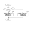
- FIG. 7 is a flow chart illustrating an example of setting processing of the main heating time for no preheating and an example of setting processing of the main heating time for with preheating.
- FIG. 10 is a diagram illustrating an example of setting the main heating time according to the amount of residual liquid when preheating is not performed and when preheating is performed; (A) is a setting example of the main heating time without preheating, and (B) is a setting example of the main heating time with preheating.
- FIG. 20 is a flowchart for explaining an example of control of the main heating time by a control unit used in Embodiment 14; FIG.
- FIG. 29 is a flowchart for explaining an example of control of the main heating time by a control unit used in Embodiment 15.
- FIG. FIG. 22 is a flowchart for explaining an example of control of main heating time by a control unit used in Embodiment 16;
- FIG. FIG. 20 is a diagram for explaining an example of the external configuration of an aerosol generating device assumed in Embodiment 17;
- FIG. 20 is a diagram schematically showing an internal configuration example of an aerosol generating device assumed in Embodiment 18;
- FIG. 1 is a diagram illustrating an example of the external configuration of an aerosol generating device 1 assumed in Embodiment 1.
- FIG. 1 The aerosol generator 1 shown in FIG. 1 is one form of electronic cigarette, and generates flavored aerosol without combustion.
- the electronic cigarette shown in FIG. 1 has a generally cylindrical shape.
- the aerosol generator 1 shown in FIG. 1 is composed of a plurality of units. In the case of FIG. 1, the multiple units are composed of a power supply unit 10, a cartridge 20 containing an aerosol source, and a cartridge 30 containing a flavor source.
- the cartridge 20 can be attached to and detached from the power supply unit 10, and the cartridge 30 can be attached to and detached from the cartridge 20.
- FIG. In other words, both the cartridge 20 and the cartridge 30 are replaceable.
- the power supply unit 10 incorporates an electronic circuit and the like.
- the power supply unit 10 is one form of a circuit unit.
- a power button 11 is provided on the side surface of the power supply unit 10 .
- the power button 11 is an example of an operation unit that is used to input user instructions to the power supply unit 10 .
- the cartridge 20 includes a liquid storage portion for storing the liquid that is the aerosol source, a liquid guide portion for drawing the liquid from the liquid storage portion by capillary action, and a heating portion for heating and vaporizing the liquid held in the liquid guide portion. and are built-in.
- a side surface of the cartridge 20 is provided with an air inlet (hereinafter referred to as an “air inlet”) 21 .
- the air that has flowed in through the air inlet holes 21 passes through the cartridge 20 and is discharged from the cartridge 30 .
- Cartridge 20 is also called an atomizer.
- the cartridge 30 incorporates a flavor unit that adds flavor to the aerosol.
- a mouthpiece 31 is provided in the cartridge 30 .
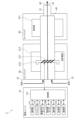
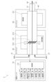
- FIG. 2 is a diagram schematically showing the internal configuration of the aerosol generator 1 assumed in the first embodiment.
- the aerosol generator 1 is composed of a power supply unit 10 and cartridges 20 and 30 .
- the power supply unit 10 incorporates a power supply unit 111, a puff sensor 112, a power button sensor 113, a notification unit 114, a storage unit 115, a communication unit 116, and a control unit 117.
- the cartridge 20 incorporates a heating portion 211 , a liquid guiding portion 212 and a liquid storing portion 213 .
- a flavor source 311 is built in the cartridge 30 .
- One end of cartridge 30 is used as mouthpiece 31 .
- An air flow path 40 connected to the air inlet 21 is formed inside the cartridges 20 and 30 .
- the power supply unit 111 is a device that stores power necessary for operation.
- the power supply unit 111 supplies electric power to each unit constituting the aerosol generation device 1 through control by the control unit 117 .
- the power supply unit 111 is composed of a rechargeable battery such as a lithium ion secondary battery, for example.
- the puff sensor 112 is a sensor that detects inhalation of aerosol by the user, and is configured by, for example, a flow rate sensor. Puff sensor 112 is an example of a first sensor.
- the power button sensor 113 is a sensor that detects an operation on the power button 11 (see FIG. 1), and is composed of, for example, a pressure sensor. In addition to the puff sensor 112 and the power button sensor 113, the power supply unit 10 is provided with various sensors.
- the notification unit 114 is a device used to notify the user of information.
- the notification unit 114 includes, for example, a light emitting device, a display device, a sound output device, and a vibration device.
- the storage unit 115 is a device that stores various information necessary for the operation of the aerosol generator 1 .
- a nonvolatile storage medium such as a flash memory is used for the storage unit 115 .
- the communication unit 116 is a communication interface conforming to a wired or wireless communication standard. Wi-Fi (registered trademark) and Bluetooth (registered trademark), for example, are used as communication standards.
- the control unit 117 is a device that functions as an arithmetic processing unit and a control unit, and controls overall operations in the aerosol generation device 1 through execution of various programs.
- the liquid storage unit 213 is a tank that stores the aerosol source. Aerosol is generated by atomization of an aerosol source stored in liquid reservoir 213 . Liquids such as water and polyhydric alcohols such as glycerin and propylene glycol are used as aerosol sources.
- the aerosol source may include tobacco-derived or non-tobacco-derived flavoring ingredients. If the aerosol-generating device 1 is a medical inhaler such as a nebulizer, the aerosol source may contain a medicament.
- the liquid guide section 212 is a member that guides and holds the liquid aerosol source from the liquid storage section 213 to the heating area.
- a member called a wick made by twisting a fiber material such as glass fiber or a porous material such as porous ceramic is used for the liquid guide portion 212 .
- the liquid guiding part 212 is composed of a wick, the aerosol source stored in the liquid storing part 213 is guided to the heating area by capillary action of the wick.
- the heating unit 211 is a member that heats the aerosol source held in the heating region to atomize the aerosol source and generate an aerosol.
- the heating part 211 is a coil and is wound around the liquid guiding part 212 .
- the area around which the coil is wound in the liquid guide portion 212 serves as a heating area. Due to the heat generated by the heating unit 211, the temperature of the aerosol source held in the heating area rises to the boiling point to generate an aerosol. A boiling point is an example of a first temperature.
- the heating unit 211 generates heat by power supply from the power supply unit 111 . Power supply to the heating unit 211 is started when a predetermined condition is satisfied. Predetermined conditions include, for example, the user's start of suction, pressing of the power button 11 a predetermined number of times, and input of predetermined information. However, in the case of the present embodiment, power supply to heating unit 211 is started upon detection of suction.
- Power supply to heating unit 211 is stopped when a predetermined condition is satisfied.
- Predetermined conditions include, for example, the end of suction by the user, the end of the main heating time described later, the long press of the power button 11, and the input of predetermined information.
- the power supply to the heating unit 211 stops when the suction ends.
- the heating unit 211 here is an example of a load that consumes power.
- Flavor source 311 is a component that imparts a flavor component to the aerosol generated within cartridge 20 .
- the flavor source 311 includes tobacco-derived or non-tobacco-derived flavor components.
- An air flow path 40 penetrating through the cartridges 20 and 30 is a flow path for air and aerosol inhaled by the user.
- the air flow path 40 has a tubular structure with the air inflow hole 21 as an air inlet and the air outflow hole 42 as an air outlet.
- a liquid guide portion 212 is arranged on the upstream side of the air channel 40, and a flavor source 311 is arranged on the downstream side thereof.
- the air that has flowed in through the air inflow hole 21 is mixed with the aerosol generated by the heating section 211 .
- the mixed gas passes through the flavor source 311 and is transported to the air outlet holes 42 as indicated by arrows 41 .
- the gas in which the aerosol and air are mixed is imparted with the flavor component of the flavor source 311 when passing through the flavor source 311 . It is also possible to use the flavor source 311 without attaching it to the cartridge 30 .
- the mouthpiece 31 is a member held by the user when inhaling.
- the mouthpiece 31 is provided with an air outlet hole 42 .
- the user can take in the gas in which the aerosol and the air are mixed into the oral cavity.
- An example of the internal configuration of the aerosol generator 1 has been described above, but the configuration shown in FIG. 2 is just one form.
- the aerosol generator 1 can be configured without the cartridge 30 . In that case, the cartridge 20 is provided with a mouthpiece 31 .
- the aerosol generator 1 can also include multiple types of aerosol sources.
- a plurality of types of aerosol generated from a plurality of types of aerosol sources may be mixed in the air flow path 40 to cause a chemical reaction, thereby generating another type of aerosol.
- the means for atomizing the aerosol source is not limited to heating by the heating unit 211 .
- induction heating techniques may be used to atomize the aerosol source.
- FIG. 3 is a diagram for explaining the preheating time LT0 and the main heating time LT11.
- A shows the arrangement of the preheating time LT0 and the main heating time LT11
- B shows the temperature change of the aerosol source.
- the vertical axis in FIG. 3A is puff intensity
- the vertical axis in FIG. 3B is temperature
- the horizontal axis in FIGS. 3A and 3B is time.
- the puff intensity is detected by a puff sensor.
- the strength of the puff is detected by the presence or absence of the puff, but it may be defined as the amount of air sucked.
- the main heating times LT1 and LT11 are times for heating the aerosol source held in the liquid guide section 212 (see FIG. 2) to the vaporization temperature.
- the main heating times LT1 and LT11 are an example of the first control.
- the preheating time LT0 is the time immediately before the main heating time LT11, as shown in FIG. 3A, and is the time for preliminarily heating the aerosol source.
- the preheating is heating for preheating the liquid temperature of the aerosol source in the liquid guide section 212 to room temperature or higher and lower than the boiling point.
- the preheating time LT0 is an example of second control.
- the main heating time when preheating is used is indicated as LT11
- the main heating time when preheating is not used is indicated as LT1 for distinction.
- the liquid temperature of the aerosol source in preheating is maintained at a target temperature near the boiling point.
- the target temperature here is an example of the second temperature.
- a predetermined fixed value is used for the preheating time LT0.
- aerosol can be generated immediately after the main heating time LT11 starts, and as a result, the total amount of aerosol generated during the main heating time LT11 can be increased.
- the time from the start of the main heating time LT11 until the temperature of the aerosol source reaches the boiling point is TD1 when preheating is not used, but is TD1 when preheating is used. It can be shortened to TD2 ( ⁇ TD1). Therefore, if the length of the main heating time LT11 is the same as when preheating is not used, more aerosol can be generated when preheating is used.
- the temperature of the heating unit 211 rises when power supply is started, and decreases when power supply is stopped.
- the temperature of the heating unit 211 during this heating time rises above the boiling point of the aerosol when power supply is started, and drops below the boiling point of the aerosol when power supply is stopped.
- the main heating time LT11 is interlocked with the suction of the aerosol generator 1 (see FIG. 1) by the user. That is, the main heating times LT1 and LT11 start when the aerosol suction is started, and the main heating times LT1 and LT11 end when the aerosol suction ends.
- the power feeding time to the heating part 211 and the aerosol generation time from the liquid guiding part 212 are substantially the same. Strictly speaking, however, the power immediately after the start of supply is consumed to raise the temperature of the aerosol source held in the liquid guide section 212 . Therefore, there is a time lag between when the liquid temperature of the aerosol source reaches the boiling point and when the aerosol starts to be generated.
- the main heating time LT11 when preheating is used is shorter than the main heating time LT1 when preheating is not used. This is to equalize the amount of aerosol generated during the main heating time LT1 and the amount of aerosol generated during the main heating time LT11. In other words, when controlling the amount of aerosol generated to be the same as in the case without preheating, the main heating time LT11 with preheating should be shorter than the main heating time LT1 without preheating. becomes possible.
- preheating accelerates the generation of aerosol is that the viscosity of the aerosol source at the start of the main heating time LT11 is lower than when preheating is not used.
- the lower the viscosity of the aerosol source the higher the liquid feeding speed to the liquid guide section 212, resulting in an increase in the amount of liquid supplied.
- the preheating time LT0 becomes longer, the amount of power consumed also increases accordingly. Therefore, it is necessary to set the length of the preheating time LT0 in consideration of the balance with the amount of power consumed during the main heating time LT11.
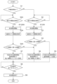
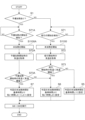
- FIG. 4 is a flowchart for explaining an example of control of the main heating time by the controller 117 (see FIG. 2) used in the first embodiment. Control by the control unit 117 is realized through execution of a program. Therefore, the control unit 117 is a form of computer. In FIG. 4, the symbol S is used to mean step.
- control unit 117 determines whether or not there is preheating (step 1). That is, control unit 117 determines whether the preheating mode is on or off.
- the aerosol generator 1 in the present embodiment is provided with a preheating mode, and whether to use the preheating mode in an ON state or an OFF state is determined by the user.
- the aerosol generator 1 may be provided with a dedicated button for turning on/off the preheating mode.
- step 1 determines whether or not the start of suction has been detected by the puff sensor 112 (see FIG. 2) (step 2). If the user's start of aerosol inhalation is not detected, the control unit 117 obtains a negative result in step 2 . While a negative result is obtained in step 2, the control unit 117 repeats the determination in step 2. On the other hand, when the user's start of aerosol inhalation is detected, the control unit 117 obtains a positive result in step 2 . If a positive result is obtained in step 2, the controller 117 starts main heating (step 1100), and then obtains the last puff interval (step 3).
- the last puff interval is given by the time from the end of the previous suction (puff) to the start of the current suction (puff).
- the puff interval may be measured, for example, by a timer, or may be calculated as the difference between the last suction end time and the current suction start time.
- the time is acquired, for example, from a timer built into the control unit 117 or an integrated circuit that realizes the timer function.
- the control unit 117 determines whether the puff interval is shorter than the first period (step 4).
- the first period is set in consideration of the ability to supply the aerosol source by the liquid guide section 212 and the time when the liquid may dry up. In the case of this embodiment, the first period is set to 10 seconds, for example. Of course, this value is an example.
- the control section 117 obtains a negative result in step 4 .
- the controller 117 sets the current main heating time LT1 to the reference time L1 (step 5).
- the reference time L1 here is an example of the second period. In this embodiment, for example, 2.4 seconds is used as the reference time. Of course, this value is an example of the reference time L1.
- the reference time L1 is set to a time during which liquid drying does not occur due to inhalation of aerosol by an assumed standard user when the puff interval is longer than the threshold.
- the control section 117 obtains a positive result in step 4. This case is called a "short puff".
- a short puff is a state in which the puff interval is shorter than the first period.
- the controller 117 sets the current main heating time LT1 to a time L2 shorter than the reference time (step 6).
- the main heating time LT1 is shortened, and the voltage value and current value supplied to the heating unit 211 are the same regardless of the difference in the puff interval.
- 1.7 seconds for example, is used as the time L2.
- this value is an example of the main heating time LT1 for short puffs. The shorter the time L2, the more difficult it is for the liquid drying phenomenon, in which no aerosol is generated even if the aerosol source is heated, to occur.
- the controller 117 determines whether or not it is time to finish the main heating (step 8).
- the main heating is ended by, for example, the end of the set main heating time LT1, the end of aerosol suction by the user, or a forced end operation. Therefore, even if the set main heating time LT1 remains, the power supply to the heating unit 211 is finished when it is determined that the main heating is finished.
- the elapse of the main heating time LT1 is monitored by the elapsed time from the start of power supply to the heating unit 211 . It should be noted that, for example, a long press of the power button 11 (see FIG. 1) is used for the forced termination operation.
- Pressing the power button 11 for a long time means that the power button 11 is continuously pressed for a predetermined time or longer. For example, when the power button 11 is pressed for three seconds or more, the control unit 117 determines that a long press operation has been performed.
- step 8 While a negative result is obtained in step 8, the control unit 117 repeats the determination in step 8. During this time, power supply to the heating unit 211 is continued. On the other hand, if a positive result is obtained in step 8, the controller 117 terminates the main heating (step 9). That is, power supply to the heating unit 211 is stopped. Thus, one cycle of suction is completed. Note that when a short puff is detected when preheating is used, the main heating time LT11 becomes shorter than the reference time L1. is smaller than the amount of electric power (reference value) supplied in the case of
- step 1 determines whether or not the last puff interval is a short puff, and to set the main heating time LT11.
- the controller 117 determines whether or not the puff sensor 112 has detected the start of suction (step 2A). If the user's start of aerosol inhalation is not detected, the control unit 117 obtains a negative result in step 2A. While a negative result is obtained in step 2A, the control section 117 repeats the determination in step 2A.
- control unit 117 obtains a positive result in step 2A. If a positive result is obtained in step 2A, control unit 117 starts main heating after completion of preheating (step 1100A), and then acquires the last puff interval (step 3A). Preheating may be started, for example, when a predetermined operation or the like on the power button 11 is detected. After obtaining the puff interval, the control unit 117 determines whether the puff interval is shorter than the first period (step 4A). However, the threshold used for determination in step 4A may be different from that in step 4. For example, the threshold used for the determination of step 4A may be smaller than the threshold used for the determination of step 4.
- the control section 117 obtains a negative result in step 4A.
- the controller 117 sets the current main heating time LT11 to a time L2 shorter than the reference time (step 6). That is, the main heating time LT11 when preheating is used is shorter than the main heating time LT1 when preheating is not used, even with the same puff interval. This prevents the drying of the liquid peculiar to preheating.
- the main heating time when a negative result is obtained in step 4A should be shorter than the reference time L1, and does not necessarily have to be L2.
- the main heating time LT11 when the short puff is not detected when preheating is used (that is, when the result is negative in step 4A), and the short puff is detected when preheating is not used.
- the main heating time LT1 is set to the same time L2 in the case of (that is, the positive result in step 4), but it does not have to be the same time.
- the length of the main heating time LT11 when a negative result is obtained in step 4A may be set to a value shorter than the length of the main heating time LT1 when a positive result is obtained in step 4A.
- step 4A the controller 117 sets the current main heating time LT11 to a time L3 ( ⁇ L2) shorter than the reference time L1 (step 7).
- the control unit 117 After setting the main heating time LT11 in step 6 or step 7, the control unit 117 sequentially executes the processing in steps 8 and 9, and completes one cycle of suction.
- FIG. 5 is a diagram illustrating an example of setting the main heating time depending on the presence or absence of preheating and the length of the puff interval.
- (A) shows a setting example of the main heating time LT1 without preheating
- (B) shows a setting example of the main heating time LT11 with preheating.
- the main heating time LT1 that is, L1 when the puff interval is long is 2.4 seconds
- the main heating time LT1 that is, L1
- L2 is 1.7 seconds.
- the main heating time LT11 (that is, L2) when the puff interval is long is 1.7 seconds
- the main heating time LT11 (that is, L2) is 1.7 seconds when the puff interval is short.
- L3 is 1.2 seconds.
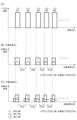
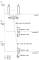
- FIG. 6 is a diagram for explaining the relationship between the puff interval and the setting of the main heating time in the first embodiment.
- A shows an example of the timing of suction (puff)
- B shows an example of setting the main heating time without preheating
- C shows an example of setting the main heating time with preheating.
- the vertical axis in FIG. 6A is puff intensity
- the vertical axis in FIGS. 6B and 6C is heating intensity
- the horizontal axis in FIGS. 6A to 6C is time.
- the intensity of heating is the amount of electric power and is given by the product of the voltage value and the current value supplied to the heating unit 211 .
- the number of suctions (puffs) in FIG. 6A is five. In the case of FIG.
- the interval between the first and second puffs is IT1
- the interval between the second and third puffs is IT2
- the interval between the third and fourth puffs is IT1.
- the interval is IT3 and the interval between the 4th and 5th puffs is IT4.
- the third and fourth puff intervals IT3 and IT4 are shorter than the first period. That is, the third and fourth puff intervals are determined as short puffs. Therefore, the first and second puff intervals IT1 and IT2 are not short puffs.
- the main heating time of the first puff, the second puff, and the third puff is set to the reference time L1, while the fourth puff is set to the reference time L1.
- the main heating time for the first puff and the fifth puff is set to a time L2 shorter than the reference time L1.
- the main heating time LT11 of the first puff, the second puff, and the third puff is set to L2, which is shorter than the reference time L1.
- the main heating time LT11 of the fourth and fifth puffs is set to a time L3 ( ⁇ L2) shorter than the reference time L1.
- the user's aerosol inhalation period and the heating time of the heating unit 211 are matched within the preset main heating time. (Refer to FIG. 1) may start the main heating, or may continue the main heating until the main heating time elapses even after the user has finished inhaling. Although the puff interval in these cases does not coincide with the time during which the main heating is stopped, it is possible to effectively suppress liquid drying during short puffs, as in the control example described above.
- the puff interval is defined as a period during which power supply to heating unit 211 (see FIG. 2) is stopped.
- power supply to the heating unit 211 is started by a predetermined operation of the power button 11 (see FIG. 1), and heating is performed when a preset main heating time elapses or when the user forcibly terminates power supply.
- Power supply to the unit 211 ends.
- the power supply to the heating unit 211 may be executed in accordance with the inhalation of the aerosol by the user.
- FIG. 7 is a flowchart for explaining an example of control of the main heating time by the controller 117 (see FIG. 2) used in the second embodiment. In FIG. 7, parts corresponding to those in FIG. Control by the control unit 117 is realized through execution of a program.
- the control unit 117 first determines whether or not there is preheating (step 1). When a negative result is obtained in step 1 (that is, when the preheating mode is off), the control unit 117 determines whether or not the start of heating by the heating unit 211 has been detected (step 11). That is, it is determined whether or not the main heating has started.
- the start of heating by the heating unit 211 is detected, for example, by an ON operation of the power button 11 (see FIG. 1), the start of suction by the user, or the like.
- the ON operation here is an operation for instructing the start of power supply to the heating unit 211, and means, for example, pressing the power button 11 for a long time.
- the start of heating of the aerosol source by the heating part 211 is detected by detection of current for main heating, detection of voltage for main heating, change in resistance value of the heating part 211, temperature rise of the liquid guide part 212, and the like.
- the control unit 117 obtains a negative result in step 11 . While a negative result is obtained in step 11, the control unit 117 repeats the determination of step 11. On the other hand, when the start of heating by the heating unit 211 is detected, the control unit 117 obtains a positive result in step 11 . If a positive result is obtained in step 11, the controller 117 acquires the last heating stop time (step 12).
- the immediately preceding heating stop time is given by the elapsed time from the end of heating in the previous suction cycle to the start of heating in the current suction cycle.
- the heating stop time refers to a period other than the main heating. Therefore, even during preheating is included in the heating stop time.
- the heating stop time may be measured, for example, by a timer, or may be calculated as the difference between the time when the previous heating was finished and the time when the current heating was started.
- the controller 117 determines whether or not the heating stop time is shorter than the first period (step 13).
- the first period here is set in consideration of the ability to supply the aerosol source by the liquid guide section 212 and the time when the liquid may dry up.
- the first period is, for example, 10 seconds. Of course, this value is an example. Note that the first period is not an absolute value.
- the controller 117 obtains a negative result in step 13 . In this case, the controller 117 sets the current main heating time to the reference time L1 (step 5). On the other hand, if the heating stop time is shorter than the first period, that is, if the short puff condition is satisfied, the controller 117 sets the current main heating time to a time L2 shorter than the reference time (step 6). After setting the main heating time LT1 in step 5 or step 6, the control unit 117 executes steps 8 and 9 in order to complete one suction cycle.
- step 11A determines whether or not the start of heating by the heating unit 211 has been detected. . That is, it is determined whether or not preheating has ended and main heating has started. If the start of heating by the heating unit 211 is not detected, the control unit 117 obtains a negative result in step 11A. While a negative result is obtained in step 11A, the control section 117 repeats the determination of step 11A. On the other hand, when the start of heating by the heating unit 211 is detected, the control unit 117 obtains a positive result in step 11A. If a positive result is obtained in step 11A, the controller 117 acquires the last heating stop time (step 12A).
- the controller 117 determines whether or not the heating stop time is shorter than the first period (step 13A).
- the threshold used for determination in step 13A may be different from that in step 13.
- the threshold used for the determination of step 13A may be smaller than the threshold used for the determination of step 13. If the heating stop time is longer than or equal to the first period, the controller 117 obtains a negative result in step 13A. In this case, the controller 117 sets the current main heating time to a time L2 shorter than the reference time L1 (step 6).
- the main heating time when a negative result is obtained in step 3A should be shorter than the reference time L1, and does not necessarily have to be L2.
- the controller 117 sets the current main heating time to a time L3 ( ⁇ L2) shorter than the reference time (step 7). ). After setting the main heating time LT11 in step 6 or step 7, the control unit 117 sequentially executes steps 8 and 9, and completes one cycle of suction.
- control unit 117 in the present embodiment detects the occurrence of short puffs that cause liquid drying, focusing on the heating stop time, which is the period during which aerosol generation is stopped. Therefore, it is possible to effectively suppress the occurrence of dryness. Also in the present embodiment, when a short puff is detected when preheating is used, the main heating time LT11 becomes shorter than the reference time L1. is smaller than the power amount (reference value) supplied for the reference time L1.
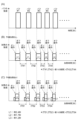
- FIG. 8 is a diagram for explaining the relationship between the puff interval and the setting of the main heating time in the second embodiment.
- (A) shows an example of the suction (puff) timing
- (B) shows an example of setting the main heating time LT1 without preheating
- (C) shows the setting of the main heating time LT11 with preheating.
- the vertical axis in FIG. 8(A) is puff intensity
- the vertical axis in FIGS. 8(B) and (C) is heating intensity
- the horizontal axis in FIGS. 8(A) to (C) is time.
- FIG. 8A shows a case where the period during which the heating unit 211 is heated does not match the period during which the user sucks.
- heating of the heating unit 211 is started by an ON operation of the power button 11 or the like, and the heating is finished after a pre-set main heating time elapses.
- the number of times of suction (puff) is five.
- the heating stop time that gives the interval between the first puff and the second puff is IT11
- the heating stop that gives the interval between the second puff and the third puff is IT12
- the heating stop time that provides the interval between the third and fourth puffs is IT13
- the heating stop time that provides the interval between the fourth and fifth puffs is IT14.
- the third and fourth puff intervals are shorter than the first period. That is, the third and fourth puff intervals are determined as short puffs.
- the main heating time LT1 of the first puff, the second puff, and the third puff is set to the reference time L1, while the fourth puff and the fifth puff are set to the reference time L1.
- the main heating time LT1 is set to a time L2 shorter than the reference time L1.
- IT21 is the heating stop time that gives the interval between the first puff and the second puff, giving the interval between the second puff and the third puff.
- the heating stop time is IT22
- the heating stop time that gives the interval between the third puff and the fourth puff is IT23
- the heating stop time that gives the interval between the fourth puff and the fifth puff is IT24.
- the third and fourth puff intervals are shorter than the first period. That is, the third and fourth puff intervals are determined as short puffs.
- the main heating time LT11 for the first puff, the second puff, and the third puff is set to L2, which is shorter than the reference time L1.
- the time LT11 is set to a time L3 ( ⁇ L2) shorter than the reference time L1.
- the puff interval is defined as the elapsed time from the stoppage of power supply to heating unit 211 (see FIG. 2) immediately before to the start of current suction. In other words, it corresponds to the combined control of the first embodiment and the second embodiment.
- Other configurations of the aerosol generator 1 (see FIG. 1) in the present embodiment are the same as in the first embodiment. That is, the external configuration and internal configuration of the aerosol generator 1 are the same as those of the first embodiment.
- FIG. 9 is a flowchart for explaining an example of control of the main heating time by the controller 117 (see FIG. 2) used in the third embodiment. In FIG. 9, parts corresponding to those in FIG. Control by the control unit 117 is realized through execution of a program.
- the control unit 117 first determines whether or not there is preheating (step 1). When a negative result is obtained in step 1 (that is, when the preheating mode is off), the control unit 117 determines whether or not the start of heating by the heating unit 211 has been detected (step 21). That is, it is determined whether or not the main heating has started. If the start of heating by the heating unit 211 is not detected, the control unit 117 obtains a negative result in step 21 . While a negative result is obtained in step 21, the control unit 117 repeats the determination of step 21.
- the control unit 117 obtains a positive result in step 21 .
- the control unit 117 acquires the last heating end time (step 22).
- the heating end time refers to the time when the main heating is completed.
- the controller 117 determines whether or not the puff sensor 112 has detected the start of suction (step 23). If the start of inhaling the aerosol by the user is not detected, the control unit 117 obtains a negative result in step 23 . While a negative result is obtained in step 23, the control unit 117 repeats the determination of step 23. Note that even when a negative result is obtained in step 23, the control unit 117 forcibly ends the heating when the predetermined condition is satisfied.
- Predetermined conditions include, for example, no puffs detected within a predetermined period of time.
- the control unit 117 obtains a positive result in step 23 . If a positive result is obtained in step 23, the control section 117 acquires the current puff start time (step 24). The current puff start time is the time when a positive result was obtained in step 23 . Subsequently, the control unit 117 calculates the elapsed time from the last heating end time to the current puff start time (step 25). After the elapsed time is calculated, the controller 117 determines whether the elapsed time is shorter than the first period (step 26).
- the control section 117 obtains a negative result in step 26 . In this case, the controller 117 sets the current main heating time to the reference time L1 (step 5). On the other hand, if the elapsed time is shorter than the threshold, the control section 117 obtains a positive result in step 26 . In this case, the controller 117 sets the current main heating time to a time L2 shorter than the reference time (step 6). After setting the main heating time LT1 in step 5 or step 6, the control unit 117 executes steps 8 and 9 in order to complete one suction cycle.
- step 21A determines whether or not the start of heating by the heating unit 211 has been detected. . That is, it is determined whether or not preheating has ended and main heating has started. If the start of heating by heating unit 211 is not detected, control unit 117 obtains a negative result in step 21A. While a negative result is obtained in step 21A, the control section 117 repeats the determination of step 21A. On the other hand, when the start of heating by heating unit 211 is detected, control unit 117 obtains a positive result in step 21A. If a positive result is obtained in step 21A, the controller 117 acquires the last heating end time (step 22A).
- the controller 117 determines whether or not the puff sensor 112 has detected the start of suction (step 23A). If the start of inhalation of aerosol by the user is not detected, control unit 117 obtains a negative result in step 23A. While a negative result is obtained in step 23A, the control section 117 repeats the determination of step 23A. On the other hand, when the start of inhalation of aerosol by the user is detected, the control section 117 obtains a positive result in step 23A. If a positive result is obtained in step 23A, the control section 117 acquires the current puff start time (step 24A). The current puff start time is the time when a positive result was obtained in step 23A.
- control unit 117 calculates the elapsed time from the last heating end time to the current puff start time (step 25A). After calculating the elapsed time, the control unit 117 determines whether the elapsed time is shorter than the first period (step 26A). However, the threshold used for the determination of step 26A may be different from step 26. For example, the threshold used for the determination of step 26A may be smaller than the threshold used for the determination of step 26. If the elapsed time is greater than or equal to the first period, control section 117 obtains a negative result in step 26A. In this case, the controller 117 sets the current main heating time to a time L2 shorter than the reference time (step 6). However, the main heating time when a negative result is obtained in step 26A should be shorter than the reference time L1, and does not necessarily have to be L2.
- the controller 117 sets the current main heating time to a time L3 ( ⁇ L2) shorter than the reference time (step 7). .
- the control unit 117 executes steps 8 and 9 in order to complete one cycle of suction.
- the control unit 117 in the present embodiment focuses on the elapsed time from the end of the previous heating to the start of the current suction of the aerosol, and the short puff that causes the liquid to dry up. Detect occurrence. Therefore, it is possible to effectively suppress the occurrence of dryness.
- the main heating time LT11 is shorter than the reference time L1. is smaller than the power amount (reference value) supplied for the reference time L1.
- FIG. 10 is a diagram for explaining the relationship between the puff interval and the setting of the main heating time in the third embodiment.
- A shows an example of the timing of suction (puff)
- B shows an example of setting the main heating time without preheating
- C shows an example of setting the main heating time with preheating.
- the vertical axis in FIG. 10(A) is puff intensity
- the vertical axis in FIGS. 10(B) and (C) is heating intensity
- the horizontal axis in FIGS. 10(A) to (C) is time.
- FIGS. 10A to 10C also show a case where the period during which the heating unit 211 is heated does not match the period during which the user sucks.
- the number of times of suction is five.
- the elapsed time giving the interval between the first puff and the second puff is IT21
- the elapsed time giving the interval between the second puff and the third puff is IT21
- IT22 the elapsed time giving the interval between the third and fourth puffs
- IT24 the elapsed time giving the interval between the fourth and fifth puffs.
- the third and fourth puff intervals are shorter than the first period. That is, the third and fourth puff intervals are determined as short puffs.
- the main heating time LT1 for the first puff, the second puff, and the third puff is set to the reference time L1, while the main heating time LT1 for the fourth puff and the fifth puff is , is set to a time L2 shorter than the reference time L1.
- the main heating time LT1 is shortened from the reference time L1. Therefore, liquid drying does not occur during the fourth puff.
- the fifth puff It should be noted that in the sixth and subsequent puffs, if the immediately preceding puff interval is longer than the threshold, the main heating time LT1 for that suction time is again set to the reference time L1.
- the elapsed time giving the interval between the first puff and the second puff is IT31
- the elapsed time giving the interval between the second puff and the third puff is IT31
- the time is IT32
- the elapsed time giving the interval between the third and fourth puffs is IT33
- the elapsed time giving the interval between the fourth and fifth puffs is IT34.
- the third and fourth puff intervals are shorter than the first period. That is, the third and fourth puff intervals are determined as short puffs.
- the main heating time LT11 for the first puff, the second puff, and the third puff is set to L2, which is shorter than the reference time L1.
- the time LT11 is set to a time L3 ( ⁇ L2) shorter than the reference time L1.
- the puff interval is defined as a period from when the power button 11 (see FIG. 1) is turned on to when it is turned off.
- power supply to the heating unit 211 starts when the power button 11 is turned on, and power supply to the heating unit 211 ends when the preset main heating time elapses or the user turns off the power button 11 .
- the termination of power supply due to the lapse of the preset main heating time is regarded as the termination of power supply due to the user's turning off operation.
- FIG. 11 is a flowchart for explaining an example of control of the main heating time by the controller 117 (see FIG. 2) used in the fourth embodiment.
- the control unit 117 first determines whether or not there is preheating (step 1). When a negative result is obtained in step 1 (that is, when the preheating mode is off), the control unit 117 determines whether or not the ON operation of the power button 11 has been detected (step 31). That is, it is determined whether or not the main heating has started.
- control unit 117 obtains a negative result in step 31 . While a negative result is obtained in step 31 , the control section 117 repeats the determination of step 31 . On the other hand, when the ON operation of the power button 11 is detected, the control unit 117 obtains a positive result in step 31 . When a positive result is obtained in step 31, the control unit 117 acquires the time of the current ON operation (step 32). When the time of the ON operation is acquired, the control unit 117 acquires the time of the previous OFF operation (step 33).
- control unit 117 calculates the elapsed time from the previous OFF operation to the current ON operation (step 34). After the elapsed time is calculated, the controller 117 determines whether the elapsed time is shorter than the first period (step 35). If the elapsed time is longer than or equal to the first period, the control section 117 obtains a negative result in step 35 . In this case, the controller 117 sets the current main heating time to the reference time L1 (step 5).
- the control unit 117 gets a positive result in step 35 .
- the controller 117 sets the current main heating time to a time L2 shorter than the reference time (step 6). After setting the main heating time in step 5 or step 6, the control section 117 executes steps 8 and 9 in order to complete one cycle.
- control unit 117 determines whether or not the ON operation of power button 11 has been detected (step 31A). That is, it is determined whether or not preheating has ended and main heating has started. If the ON operation of the power button 11 is not detected, the controller 117 obtains a negative result in step 31A. While a negative result is obtained in step 31A, the control section 117 repeats the determination of step 31A. On the other hand, when the ON operation of power button 11 is detected, control unit 117 obtains a positive result in step 31A. If a positive result is obtained in step 31A, control unit 117 acquires the time of the current ON operation (step 32A).
- the control unit 117 acquires the time of the previous OFF operation (step 33A). Next, the control unit 117 calculates the elapsed time from the previous OFF operation to the current ON operation (step 34A). After the elapsed time is calculated, the controller 117 determines whether the elapsed time is shorter than the first period (step 35A). However, the threshold used for determination in step 35A may be different from step 35. For example, the threshold used for the determination of step 35A may be smaller than the threshold used for the determination of step 35.
- control section 117 obtains a negative result in step 35A.
- the controller 117 sets the current main heating time to a time L2 shorter than the reference time (step 6).
- the main heating time when a negative result is obtained in step 35A may be shorter than the reference time L1, and does not necessarily have to be L2.
- control unit 117 obtains a positive result at step 35A.
- the controller 117 sets the current main heating time to a time L3 ( ⁇ L2) shorter than the reference time (step 7). After setting the main heating time in step 6 or step 7, the control unit 117 executes steps 8 and 9 in order to complete one cycle of suction.
- the control unit 117 detects the occurrence of short puffs that cause liquid drying, based on the relationship between the first period and the elapsed time from the OFF operation to the ON operation of the power button 11. . Therefore, it is possible to effectively suppress the occurrence of dryness. Also in the present embodiment, when a short puff is detected when preheating is used, the main heating time is shorter than the reference time L1, so the amount of power supplied to heating unit 211 during one suction cycle is , the amount of electric power (reference value) supplied in the case of the reference time L1.
- FIG. 12 is a diagram for explaining the relationship between the puff interval and the setting of the main heating time in the fourth embodiment.
- (A) shows an example of the timing of suction (puff)
- (B) shows an example of setting the main heating time without preheating
- (C) shows an example of setting the main heating time with preheating. show.
- the vertical axis in FIG. 12(A) is puff intensity
- the vertical axis in FIGS. 12(B) and (C) is heating intensity
- the horizontal axis in FIGS. 12(A) to (C) is time.
- FIGS. 12A to 12C also show a case where the period during which the heating unit 211 is heated does not match the period during which the user sucks. That is, it represents the case where the user inhales the aerosol during an arbitrary period within the main heating period started by turning on the power button 11 .
- the number of times of suction is five.
- the elapsed time giving the interval between the first puff and the second puff is IT41
- the elapsed time giving the interval between the second puff and the third puff is IT41
- IT42 the elapsed time giving the interval between the third and fourth puffs
- IT44 the elapsed time giving the interval between the fourth and fifth puffs.
- the third and fourth puff intervals are shorter than the first period. That is, the third and fourth puff intervals are determined as short puffs.
- the main heating time LT1 for the first puff, the second puff, and the third puff is set to the reference time L1, while the main heating time LT1 for the fourth puff and the fifth puff is , is set to a time L2 shorter than the reference time L1.
- the main heating time LT1 is shortened from the reference time L1. Therefore, liquid drying does not occur during the fourth puff.
- the fifth puff It should be noted that in the sixth and subsequent puffs, if the immediately preceding puff interval is longer than the threshold, the main heating time LT1 for that suction time is again set to the reference time L1.
- the elapsed time giving the interval between the first puff and the second puff is IT51
- the elapsed time giving the interval between the second puff and the third puff is IT52
- the elapsed time giving the interval between the third and fourth puffs is IT53
- the elapsed time giving the interval between the fourth and fifth puffs is IT54.
- the third and fourth puff intervals are shorter than the first period. That is, the third and fourth puff intervals are determined as short puffs.
- the main heating time LT11 for the first puff, the second puff, and the third puff is set to L2, which is shorter than the reference time L1.
- the time LT11 is set to a time L3 ( ⁇ L2) shorter than the reference time L1.
- Embodiment 5 will explain an example of a technique for indirectly detecting the occurrence of a short puff.
- reheating of the aerosol source is started before the liquid temperature of the aerosol source in the liquid guide section 212 has fully decreased.
- This embodiment focuses on this phenomenon.
- the external configuration of the aerosol generator 1 is the same as that of the first embodiment.
- the internal configuration of the aerosol generator 1 assumed in this embodiment is partially different from that in the first embodiment.
- FIG. 13 is a diagram schematically showing the internal configuration of the aerosol generating device 1 assumed in Embodiment 5. As shown in FIG. In FIG. 13, parts corresponding to those in FIG. 2 are shown with reference numerals corresponding thereto.
- the aerosol generator 1 shown in FIG. 13 is different from the aerosol generator 1 shown in FIG. 2 in that a coil temperature sensor 113A is provided.
- the heating unit 211 is a coil.
- a thermistor for example, is used for the coil temperature sensor 113A.
- a thermistor is placed near the coil.
- Coil temperature sensor 113A is an example of a second sensor.
- the current value flowing through the heating unit 211 may be measured, or the voltage appearing in the resistor connected in series to the heating unit 211 may be measured.
- the puff interval is short, the temperature of the heating unit 211 at the start of suction becomes higher than when the puff interval is long, and the resistance value of the heating unit 211 becomes large. Therefore, when the puff interval is short, the current is less likely to flow than when the puff interval is long.
- Sensing of the temperature of the part 211 is possible. For example, if a table that associates the current value or voltage value with the temperature of the heating unit 211 is prepared, the control unit 117 reads the temperature corresponding to the measured current value or voltage value from the table. Further, for example, if a conversion formula for the current value or voltage value and the temperature of the heating unit 211 is prepared, the control unit 117 substitutes the measured current value or voltage value for variables to calculate the corresponding temperature. .
- FIG. 14 is a flowchart for explaining an example of control of the main heating time by the controller 117 (see FIG. 2) used in the fifth embodiment.
- the control unit 117 first determines whether or not there is preheating (step 1).
- step 41 determines whether or not the puff sensor 112 has detected the start of suction. If the start of aerosol inhalation by the user is not detected, the control unit 117 obtains a negative result in step 41 . While a negative result is obtained in step 41 , the control section 117 repeats the determination of step 41 .
- the control unit 117 obtains a positive result in step 41 .
- the control unit 117 starts main heating (step 1100), and then acquires the temperature of the coil at the start of suction (step 42).
- the temperature of the coil is the temperature of the heating unit 211 .
- the control unit 117 determines whether the temperature of the coil at the start of suction is higher than the first temperature reference (step 43).
- a first temperature reference is set to an intermediate value between the temperature encountered for short puffs and the temperature encountered for non-short puffs.
- the control unit 117 obtains a negative result in step 43 . In this case, the controller 117 sets the current main heating time to the reference time L1 (step 5). On the other hand, if the temperature of the coil is higher than the first temperature criterion, the controller 117 obtains a positive result in step 43 . In this case, the controller 117 sets the current main heating time to a time L2 shorter than the reference time (step 6). After setting the main heating time in step 5 or step 6, the control unit 117 executes steps 8 and 9 in order to complete one cycle of suction.
- step 41A determines whether or not the start of preheating has been detected. If the start of preheating is not detected, control unit 117 obtains a negative result in step 41A. While a negative result is obtained in step 41A, the control section 117 repeats the determination of step 41A.
- control unit 117 obtains a positive result in step 41A. If a positive result is obtained in step 41A, control unit 117 starts main heating after preheating ends (step 1100A), and then obtains the temperature of the coil at the start of preheating (step 42A). When the coil temperature is obtained, the control unit 117 determines whether the coil temperature at the start of preheating is higher than the first temperature reference (step 43A). However, the threshold used for the determination in step 43A may be different from that in step 43. For example, the threshold used for the determination of step 43A may be smaller than the threshold used for the determination of step 43.
- control unit 117 obtains a negative result in step 43A.
- the controller 117 sets the current main heating time to a time L2 shorter than the reference time (step 6).
- the main heating time when a negative result is obtained in step 43A should be shorter than the reference time L1, and does not necessarily have to be L2.
- control unit 117 obtains a positive result at step 43A.
- the controller 117 sets the current main heating time to a time L3 ( ⁇ L2) shorter than the reference time (step 7). After setting the main heating time in step 6 or step 7, the control unit 117 executes steps 8 and 9 in order to complete one cycle of suction.
- control unit 117 focuses on the temperature of the heating unit 211 that generates the aerosol, and detects the occurrence of short puffs that cause liquid drying. Therefore, it is possible to effectively suppress the occurrence of dryness.
- the main heating time LT11 is shorter than the reference time L1. is smaller than the power amount (reference value) supplied for the reference time L1.
- FIG. 15 is a diagram for explaining the relationship between the puff interval and the setting of the main heating time in the fifth embodiment.
- A shows an example of the suction (puff) timing
- B shows the temperature change of the heating unit 211 without preheating
- C shows an example of setting the main heating time without preheating
- D shows the temperature change of the heating unit 211 with preheating
- E shows a setting example of the main heating time with preheating.
- the vertical axis in FIG. 15(A) is puff intensity
- the vertical axis in FIGS. 15(B) and (D) is temperature
- the vertical axis in FIGS. 15(C) and (E) is heating intensity.
- the horizontal axis of FIGS. 15A to 15E is time.
- the number of times of suction (puff) is five.
- the temperature TA of the heating unit 211 at the start of the first puff, the second puff, the third puff, and the fifth puff is the first temperature. Lower than temperature standard.
- the temperature TB of the heating unit 211 at the start of the fourth puff is higher than the first temperature reference. This is because the puff interval is short and the cooling of the heating unit 211 is not in time.
- the main heating time LT1 of the first puff, the second puff, the third puff, and the fifth puff is set to the reference time L1.
- the main heating time LT1 of the fourth puff is set to a time L2 shorter than the reference time L1.
- the temperature TA of the heating unit 211 at the start of the first puff, the second puff, the third puff, and the fifth puff is Lower than the first temperature reference.
- the temperature TB of the heating unit 211 at the start of the fourth puff is higher than the first temperature reference. Therefore, in the example shown in FIG. 15(E) , the main heating time LT11 of the first puff, the second puff, the third puff, and the fifth puff is set to the time L2, The main heating time for the fourth puff is set to time L3.
- the main heating time LT11 is shortened from the reference time L1. Therefore, liquid drying does not occur during the fourth puff.
- Embodiment 6 also describes an example of a technique for indirectly detecting the occurrence of short puffs. In the present embodiment, it is detected through a change in resistance that the heating portion 211 is in a high temperature state at the start of suction.
- the external configuration of the aerosol generator 1 is the same as that of the first embodiment. However, the internal configuration of the aerosol generator 1 assumed in this embodiment is partially different from that in the first embodiment.
- FIG. 16 is a diagram schematically showing the internal configuration of the aerosol generator 1 assumed in Embodiment 6. As shown in FIG. In FIG. 16, parts corresponding to those in FIG. 2 are shown with reference numerals corresponding thereto.
- the aerosol generator 1 shown in FIG. 16 is different from the aerosol generator 1 shown in FIG. 2 in that a resistance value sensor 113B is provided. Note that the resistance value sensor 113B measures the resistance value of the heating unit 211 .
- the resistance value sensor 113B detects the resistance value of the heating unit 211 by measuring the value of current flowing through the heating unit 211, for example. This method detects changes in the resistance value due to temperature changes in the heating unit 211 as changes in the current value.
- the resistance value sensor 113B detects a change in the resistance value of the heating unit 211 by measuring the voltage value appearing across the resistor connected in series with the heating unit 211, for example. This method detects changes in the resistance value of the heating unit 211 due to temperature changes through changes in voltage appearing across a resistor connected in series to the heating unit 211 .
- FIG. 17 is a flowchart for explaining an example of control of the main heating time by the controller 117 (see FIG. 2) used in the sixth embodiment.
- Control by the control unit 117 is realized through execution of a program.
- Control unit 117 in the present embodiment also first determines whether or not there is preheating (step 1). When a negative result is obtained in step 1 (that is, when the preheating mode is off), the control unit 117 determines whether or not the puff sensor 112 has detected the start of suction (step 51). This determination is performed when main heating is initiated by the user's initiation of suction.
- step 51 it may be determined whether or not the heating of the heating unit 211 has started as in the case of the second embodiment. It may be determined whether or not an ON operation has been performed. If the start of aerosol inhalation by the user is not detected, the control unit 117 obtains a negative result in step 51 . While a negative result is obtained in step 51 , the control section 117 repeats the determination of step 51 .
- the control unit 117 obtains a positive result in step 51 .
- the controller 117 starts main heating (step 1100), and then acquires the resistance value of the coil at the start of suction (step 52).
- the resistance value of the coil is the resistance value of the heating unit 211 .
- the control unit 117 determines whether the resistance value of the coil at the start of suction is greater than the first resistance value (step 53).
- the first resistance value is determined according to the actual measurement value of the change in the resistance value according to the elapsed time from the end of the power supply to the heating unit 211 .
- the first resistance value is set to an intermediate value between the resistance value that appears for short puffs and the resistance value that appears for non-short puffs.
- the controller 117 obtains a negative result in step 53 . In this case, the controller 117 sets the current main heating time to the reference time L1 (step 5). On the other hand, if the resistance value of the coil is greater than the first resistance value, the controller 117 obtains a positive result in step 53 . In this case, the controller 117 sets the current main heating time to a time L2 shorter than the reference time (step 6). After setting the main heating time in step 5 or step 6, the control unit 117 executes steps 8 and 9 in order to complete one cycle of suction.
- control unit 117 determines whether or not the start of preheating has been detected (step 51A). If the start of preheating is not detected, control unit 117 obtains a negative result in step 51A. While a negative result is obtained in step 51A, the control section 117 repeats the determination of step 51A. On the other hand, if the start of preheating is detected, control unit 117 obtains a positive result in step 51A. If a positive result is obtained in step 51A, the control unit 117 starts main heating after the end of preheating (step 1100A), and then acquires the resistance value of the coil at the start of preheating (step 52A). .
- control unit 117 determines whether the resistance value of the coil at the start of preheating is greater than the first resistance value (step 53A).
- the threshold used for the determination in step 53A may be different from that in step 53.
- the threshold used for the determination of step 53A may be smaller than the threshold used for the determination of step 53.
- control section 117 obtains a negative result in step 53A.
- the controller 117 sets the current main heating time to a time L2 shorter than the reference time (step 6).
- the main heating time when a negative result is obtained in step 53A should be shorter than the reference time L1, and does not necessarily have to be L2.
- control section 117 obtains a positive result in step 53A.
- the controller 117 sets the current main heating time to a time L3 ( ⁇ L2) shorter than the reference time (step 7). After setting the main heating time in step 6 or step 7, the control unit 117 executes steps 8 and 9 in order to complete one cycle of suction.
- control unit 117 focuses on the resistance value of the heating unit 211 that generates the aerosol, and detects the occurrence of short puffs that cause liquid drying. Therefore, it is possible to effectively suppress the occurrence of dryness. Also in the present embodiment, when a short puff is detected during preheating, the main heating time LT11 is shorter than the reference time L1. It is smaller than the electric energy (reference value) supplied in the case of the reference time L1.
- FIG. 18 is a diagram explaining the relationship between the puff interval and the setting of the main heating time in the sixth embodiment.
- A shows an example of the suction (puff) timing
- B shows the change in the resistance value of the heating unit 211 without preheating
- C shows the main heating time setting without preheating
- D shows a change in the resistance value of the heating unit 211 with preheating
- E shows a setting example of the main heating time with preheating.
- the vertical axis in FIG. 18(A) is puff intensity
- the vertical axis in FIGS. 18(B) and (D) is resistance value
- the vertical axis in FIGS. 18(C) and (E) is heating intensity.
- the horizontal axis of FIGS. 18A to 18E is time.
- the number of times of suction (puff) is five.
- the interval between the first puff and the second puff and the interval between the second puff and the third puff are relatively long, and the interval between the third and fourth puffs and the fourth puff are relatively long. It is assumed that the interval between the first puff and the fifth puff is relatively short. Therefore, in the example of FIG. 18B, the coil resistance value RA at the start of the second puff, at the start of the third puff, and at the start of the fifth puff is higher than the first resistance value. is also at a low level. This is because the temperature of the coil has decreased and the resistance value has also decreased as a result of the passage of time since the end of the previous heating.
- the resistance value RB of the coil at the start of the fourth puff is higher than the first resistance value. This is because the interval between the third and fourth puffs is short, and the temperature of the heating unit 211 has not sufficiently decreased. Therefore, in the example shown in FIG. 18C, the main heating time LT1 for the first, second, third, and fifth puffs is set to the reference time L1, while the main heating time for the fourth puff is set to the reference time L1. LT1 is set to a time L2 shorter than the reference time L1. As a result, even when the puff interval until the start of the fourth puff is short and the supply amount of the aerosol source supplied to the heating unit 211 before the start of suction is small, the main heating time LT1 is shortened from the reference time L1. Therefore, liquid drying does not occur during the fourth puff.
- the resistance value RA of the coil at the start of preheating is lower than the first resistance value. This is because the temperature of the coil has decreased and the resistance value has also decreased as a result of the passage of time since the end of the previous heating.
- the resistance value RB of the coil at the start of the fourth preheating is higher than the first resistance value. This is because the interval between the third and fourth puffs is short, and the temperature of the heating unit 211 has not sufficiently decreased. Therefore, in the example shown in FIG. 18E, the main heating time LT11 for the first, second, third, and fifth puffs is set to time L2, while the main heating time LT11 for the fourth puff is set to L2. It is set at time L3. As a result, even if the puff interval until the start of the fourth puff is short and the supply amount of the aerosol source supplied to the heating unit 211 before the start of suction is small, the main heating time LT11 is shortened from the reference time L1. Therefore, liquid drying does not occur during the fourth puff.
- Embodiment 7 also describes an example of a technique for indirectly detecting the occurrence of short puffs.
- it is detected through the temperature change of the liquid guide portion 212 that the heating portion 211 is in a high temperature state at the start of suction.
- the external configuration of the aerosol generator 1 is the same as that of the first embodiment.
- the internal configuration of the aerosol generator 1 assumed in this embodiment is partially different from that in the first embodiment.
- FIG. 19 is a diagram schematically showing the internal configuration of the aerosol generator 1 assumed in Embodiment 7. As shown in FIG. In FIG. 19, parts corresponding to those in FIG. 2 are shown with reference numerals corresponding thereto.
- the aerosol generator 1 shown in FIG. 19 is different from the aerosol generator 1 shown in FIG. 2 in that a liquid temperature sensor 113C is provided.
- the temperature of the liquid guide portion 212 is measured by the liquid temperature sensor 113C. Therefore, the liquid temperature sensor 113 ⁇ /b>C is arranged near the liquid guide section 212 .
- a temperature sensor or a thermistor, for example, is used as the liquid temperature sensor 113C.
- Liquid temperature sensor 113C is an example of a third sensor.
- FIG. 20 is a flowchart for explaining an example of control of the main heating time by the controller 117 (see FIG. 2) used in the seventh embodiment.
- Control by the control unit 117 is realized through execution of a program.
- Control unit 117 in the present embodiment also first determines whether or not there is preheating (step 1). If a negative result is obtained in step 1 (that is, if the preheating mode is off), the controller 117 determines whether or not the puff sensor 112 has detected the start of suction (step 61). If the start of inhalation of the aerosol by the user is not detected, the control unit 117 obtains a negative result in step 61 . While a negative result is obtained in step 61 , the control section 117 repeats the determination of step 61 .
- the control unit 117 obtains a positive result in step 61 . If a positive result is obtained in step 61, the controller 117 starts main heating (step 1100), and then obtains the liquid temperature at the start of suction (step 62).
- the liquid temperature is the temperature of the liquid guide section 212 .
- the control section 117 determines whether or not the liquid temperature at the start of suction is higher than the second temperature reference (step 63).
- the second temperature reference is determined according to the measured value of the liquid temperature change according to the elapsed time from the end of power supply to the heating unit 211 .
- step 63 If the liquid temperature is equal to or lower than the second temperature reference, the control section 117 obtains a negative result in step 63 . In this case, the controller 117 sets the current main heating time to the reference time L1 (step 5). On the other hand, if the liquid temperature is higher than the second temperature reference, the controller 117 obtains a positive result in step 63 . In this case, the controller 117 sets the current main heating time to a time L2 shorter than the reference time (step 6). After setting the main heating time in step 5 or step 6, the control unit 117 executes steps 8 and 9 in order to complete one cycle of suction.
- control unit 117 determines whether or not the start of preheating has been detected (step 61A). If the start of preheating is not detected, control unit 117 obtains a negative result in step 61A. While a negative result is obtained in step 61A, the control section 117 repeats the determination of step 61A.
- control unit 117 obtains a positive result in step 61A. If a positive result is obtained in step 61A, the controller 117 starts main heating after preheating (step 1100A), and then obtains the liquid temperature at the start of preheating (step 62A).
- the liquid temperature is the temperature of the liquid guide section 212 .
- the control section 117 determines whether or not the liquid temperature at the start of preheating is higher than the second temperature reference (step 63A). However, the threshold used for determination in step 63A may be different from that in step 63.
- the threshold used for the determination of step 63A may be smaller than the threshold used for the determination of step 63. If the liquid temperature is less than or equal to the second temperature reference, control unit 117 obtains a negative result in step 63A. In this case, the controller 117 sets the current main heating time to a time L2 shorter than the reference time (step 6). However, the main heating time when a negative result is obtained in step 63A may be shorter than the reference time L1, and does not necessarily have to be L2. On the other hand, if the liquid temperature is higher than the second temperature reference, control unit 117 obtains a positive result in step 63A. In this case, the controller 117 sets the current main heating time to a time L3 ( ⁇ L2) shorter than the reference time (step 7). After setting the main heating time in step 6 or step 7, the control unit 117 executes steps 8 and 9 in order to complete one cycle of suction.
- control unit 117 focuses on the temperature of the liquid in the heating unit 211 that generates the aerosol, and detects the occurrence of short puffs that cause the liquid to dry up. Therefore, it is possible to effectively suppress the occurrence of dryness.
- the main heating time LT11 is shorter than the reference time L1. is smaller than the power amount (reference value) supplied for the reference time L1.
- FIG. 21 is a diagram explaining the relationship between the puff interval and the setting of the main heating time in the seventh embodiment.
- A shows an example of the suction (puff) timing
- B shows the change in temperature of the liquid guide section 212 without preheating
- C shows the main heating time setting without preheating
- D shows a change in the temperature of the liquid guide section 212 with preheating
- E shows a setting example of the main heating time with preheating.
- the vertical axis in FIG. 21(A) is puff intensity
- the vertical axis in FIGS. 21(B) and (D) is temperature
- the vertical axis in FIGS. 21(C) and (E) is heating intensity.
- the horizontal axis of FIGS. 21A to 21E is time.
- the number of times of suction (puff) is five.
- the interval between the first and second puffs and the interval between the second and third puffs are relatively long, and the interval between the third and fourth puffs is 4.
- the interval between the first puff and the fifth puff is relatively short. Therefore, in the example of FIG. 21B corresponding to no preheating, at the start of the first puff, at the start of the second puff, at the start of the third puff, and at the start of the fifth puff, The fluid temperature TA at the start is lower than the second temperature reference. This is because heating is started in a state where the liquid temperature has dropped to or near room temperature as a result of the passage of time since the end of the previous heating.
- the liquid temperature TB at the start of the fourth puff is higher than the second temperature reference. This is because the interval between the third puff and the fourth puff is short, and the temperature of the liquid guide portion 212 has not sufficiently decreased. Therefore, in the example shown in FIG. 21C, the main heating time LT1 of the first puff, the second puff, the third puff, and the fifth puff is set to the reference time L1. , the main heating time LT1 of the fourth puff is set to a time L2 shorter than the reference time L1. As a result, even if the puff interval until the start of the fourth puff is short and the supply amount of the aerosol source supplied to the heating unit 211 before the start of suction is small, the main heating time LT1 is shortened from the reference time L1. Therefore, liquid drying does not occur during the fourth puff.
- Liquid temperature TA is lower than the second temperature reference. This is because, as a result of the passage of time since the end of the previous heating, heating is started in a state where the liquid temperature has dropped to or near room temperature. However, the liquid temperature TB at the start of the fourth puff is higher than the second temperature reference. This is because the interval between the third puff and the fourth puff is short, and the temperature of the liquid guide portion 212 has not sufficiently decreased.
- the main heating time LT11 of the first puff, the second puff, the third puff, and the fifth puff is set to the time L2, while the main heating time LT11 is set to the time L2.
- the main heating time LT11 of the first puff is set to time L3.
- the main heating time LT11 corresponding to the fourth puff is shortened, even if the interval between the fourth puff and the fifth puff is short, the heating stop time of the heating unit 211 is lengthened. Therefore, the liquid temperature can be lowered below the second temperature reference by the time the fifth puff is started. Therefore, the main heating time LT11 corresponding to the fifth puff returns to time L2 again.
- FIG. 22 is a diagram schematically showing the internal configuration of the aerosol generator 1 assumed in the eighth embodiment. In FIG. 22, parts corresponding to those in FIG. 2 are shown with reference numerals.
- the aerosol generator 1 shown in FIG. 22 is different from the aerosol generator 1 shown in FIG. 2 in that an air temperature sensor 113D is provided. Air temperature sensor 113D is intended for measuring ambient temperature. Therefore, it is desirable to place the air temperature sensor 113D as far away from the heat source in the device as possible. Since the viscosity of the aerosol source depends on the liquid temperature of the aerosol source stored in the liquid reservoir 213 , a liquid temperature sensor may be arranged near the liquid reservoir 213 .
- FIG. 23 is a flowchart for explaining an example of control of the main heating time by the controller 117 (see FIG. 2) used in the eighth embodiment.
- Control by the control unit 117 is realized through execution of a program.
- Control unit 117 in the present embodiment also first determines whether or not there is preheating (step 1). When a negative result is obtained in step 1 (that is, when the preheating mode is off), the control unit 117 determines whether or not the puff sensor 112 has detected the start of suction (step 71). This determination is performed when main heating is initiated by the user's initiation of suction.
- step 71 If the start of inhalation of the aerosol by the user is not detected, the controller 117 obtains a negative result in step 71 . While a negative result is obtained in step 71 , the control section 117 repeats the determination of step 71 . On the other hand, when the start of inhalation of aerosol by the user is detected, the control unit 117 obtains a positive result in step 71 . If a positive result is obtained in step 71, the controller 117 starts main heating (step 1100), and then obtains the air temperature at the start of suction (step 72). The air temperature is the air temperature around the aerosol generator 1 .
- the control unit 117 determines whether or not the temperature at the start of suctioning is lower than a temperature determination threshold (hereinafter referred to as "temperature threshold”) (step 73).
- the air temperature threshold is determined according to the relationship between the viscosity of the aerosol source and air temperature.
- the controller 117 obtains a negative result in step 73 . In this case, the controller 117 sets the current main heating time to the reference time L1 (step 5). On the other hand, if the temperature is lower than the temperature threshold, the controller 117 obtains a positive result in step 73 . In this case, the controller 117 sets the current main heating time to a time L2 shorter than the reference time (step 6). After setting the main heating time LT1 in step 5 or step 6, the control unit 117 executes steps 8 and 9 in order to complete one suction cycle.
- step 71A determines whether or not the start of preheating has been detected. If the start of preheating is not detected, control unit 117 obtains a negative result in step 71A. While a negative result is obtained in step 71A, the control section 117 repeats the determination of step 71A. On the other hand, if the start of preheating is detected, control unit 117 obtains a positive result in step 71A. If a positive result is obtained in step 71A, control unit 117 starts main heating after preheating is completed (step 1100A), and then acquires the temperature at the start of preheating (step 72A).
- the control unit 117 determines whether or not the temperature at the start of preheating is lower than the temperature threshold for temperature determination (step 73A).
- the threshold used for the determination in step 73A may be different from that in step 73.
- the threshold used for the determination of step 73A may be smaller than the threshold used for the determination of step 73.
- control unit 117 obtains a negative result in step 73A.
- the controller 117 sets the current main heating time to a time L2 shorter than the reference time (step 6).
- the main heating time when a negative result is obtained in step 73A should be shorter than the reference time L1 and does not necessarily have to be L2.
- the controller 117 obtains a positive result in step 73A.
- the controller 117 sets the current main heating time to a time L3 ( ⁇ L2) shorter than the reference time (step 7). After setting the main heating time LT11 in step 6 or step 7, the control unit 117 sequentially executes steps 8 and 9, and completes one cycle of suction.
- FIG. 24 is a diagram for explaining the relationship between the puff interval and the setting of the main heating time in the eighth embodiment.
- (A) shows an example of the timing of suction (puff)
- (B) shows changes in ambient temperature
- (C) shows an example of setting the main heating time without preheating
- (D) shows a preliminary An example of setting the main heating time with heating is shown.
- the vertical axis in FIG. 24(A) is puff intensity
- the vertical axis in FIG. 24(B) is temperature
- the vertical axis in FIGS. 24(C) and (D) is heating intensity
- the horizontal axis in A) to (D) is time.
- FIG. 24(B) shows changes in ambient temperature around which the aerosol generator 1 is used.
- the temperature drops enough to affect the viscosity of the aerosol source as a result of moving from a heated room to the outdoors in winter.
- the number of times of suction (puff) is five.
- the interval between the first puff and the second puff, the interval between the second puff and the third puff, the interval between the third puff and the fourth puff, the fourth puff and 5 None of the intervals between the puffs of the second round are short puffs.
- the 1st, 2nd and 3rd puffs were performed indoors, while the 4th and 5th puffs were performed outdoors. Therefore, in FIG. 24B, the temperature drops between the third puff and the fourth puff.
- the main heating time LT1 of the first puff, the second puff, and the third puff is set to the reference time L1, while the fourth puff and the main heating time LT1 are set to the reference time L1.
- the main heating time LT1 of the fifth puff is set to a time L2 shorter than the reference time L1.
- the main heating time LT11 for the first puff, the second puff, and the third puff is set to the time L2, while the fourth puff and the fifth puff puff main heating time LT11 is set to time L3.
- the main heating time LT11 is equal to the reference time L1. Since the time is further shortened, drying of the liquid does not occur.
- FIG. 25 is a flowchart for explaining an example of control of the main heating time by the controller 117 (see FIG. 2) used in the ninth embodiment. In FIG. 25, parts corresponding to those in FIG. 4 are shown with reference numerals. Control by the control unit 117 is realized through execution of a program. Control unit 117 in the present embodiment first determines whether or not there is preheating (step 1).
- step 81 determines whether or not the puff sensor 112 has detected the start of suction. If the start of aerosol inhalation by the user is not detected, the control unit 117 obtains a negative result in step 81 . While a negative result is obtained in step 81 , the control section 117 repeats the determination of step 81 . On the other hand, when the start of inhalation of aerosol by the user is detected, the control unit 117 obtains a positive result in step 81 . If a positive result is obtained in step 81, the control unit 117 starts main heating (step 1100), and then acquires a history of past puff intervals (step 82).
- the number of puff interval histories to be acquired is preset. For example, a history of 3 to 5 times is acquired. Since the purpose is to prevent the liquid from drying up in the next suction session, even if the number of samples to be acquired is increased too much, the latest suction tendency cannot be determined. On the other hand, if the number of histories to be acquired is increased, it becomes possible to analyze the user's long-term inhalation tendency.
- the control unit 117 predicts the next puff interval (step 83). In the above-described embodiment, the latest puff interval is obtained each time a new suction cycle is started, but in the present embodiment, the puff interval is predicted before the next suction cycle is started. .
- control unit 117 determines whether or not the predicted next puff interval is shorter than the first period (step 84). If the predicted next puff interval is greater than or equal to the first period, control section 117 obtains a negative result in step 84 . In this case, the controller 117 sets the current main heating time to the reference time L1 (step 5). On the other hand, if the predicted next puff interval is shorter than the first period, the controller 117 gets a positive result at step 84 . In this case, the controller 117 sets the current main heating time to a time L2 shorter than the reference time (step 6). After setting the main heating time LT1 in step 5 or step 6, the control section 117 executes steps 8 and 9 in order to complete one suction cycle.
- step 81A determines whether or not the puff sensor 112 has detected the start of suction. If the start of inhalation of aerosol by the user is not detected, control unit 117 obtains a negative result in step 81A. While a negative result is obtained in step 81A, the control section 117 repeats the determination of step 81A. On the other hand, when the start of inhalation of aerosol by the user is detected, the control unit 117 obtains a positive result in step 81A.
- step 81A If a positive result is obtained in step 81A, the control section 117 starts main heating after the end of preheating (step 1100A), and then obtains a history of past puff intervals (step 82A). After acquiring the history of the puff intervals of a plurality of times in the past, the control section 117 predicts the next puff interval (step 83A). Subsequently, the control unit 117 determines whether or not the predicted next puff interval is shorter than the first period (step 84A). However, the threshold used for the determination of step 84A may be different from step 84. For example, the threshold used for the determination of step 84A may be less than the threshold used for the determination of step 84.
- control section 117 obtains a negative result in step 84A.
- the controller 117 sets the current main heating time to a time L2 shorter than the reference time L1 (step 6).
- the main heating time when a negative result is obtained in step 84A should be shorter than the reference time L1, and does not necessarily have to be L2.
- control unit 117 obtains a positive result at step 84A.
- the controller 117 sets the current main heating time to a time L3 ( ⁇ L2) shorter than the reference time (step 7). After setting the main heating time LT11 in step 6 or step 7, the control unit 117 sequentially executes steps 8 and 9, and completes one cycle of suction.
- control unit 117 preemptively shortens the main heating time when the predicted value satisfies the short puff condition.
- the next main heating time is the same as in the above-described other embodiments.
- the main heating time is shorter than in the above-described other embodiments.
- the puff interval until the next suction time is substantially longer, and drying up of the liquid is less likely to occur.
- the main heating time LT11 is shorter than the reference time L1. less than the amount of power (reference value) supplied to the
- FIG. 26 is a diagram for explaining the relationship between the puff interval and the setting of the main heating time in the ninth embodiment.
- (A) shows an example of the timing of suction (puff)
- (B) shows an example of setting the main heating time when the predicted puff interval is longer than or equal to the first period
- (C) shows the predicted puff interval. is shorter than the first period.
- the vertical axis in FIG. 26(A) is puff intensity
- the vertical axis in FIGS. 26(B) and (C) is heating intensity
- the horizontal axis in FIGS. 26(A) to (C) is time.
- the next puff interval is predicted from N puff intervals before the M+1 puff starts.
- FIG. 26A shows an example of the timing of suction (puff)
- (B) shows an example of setting the main heating time when the predicted puff interval is longer than or equal to the first period
- (C) shows the predicted puff interval. is shorter than the first period.
- the vertical axis in FIG. 26(A) is puff
- the predicted puff interval is not a short puff, so the main heating time LT1 is set to the reference time L1 when preheating is not performed, and the main heating time LT11 is set to the reference time L1 when preheating is performed. It is set to L2.
- the main heating time LT1 is set to time L2 when preheating is not performed, and the main heating time LT11 is set to time L3 when preheating is performed. is set.
- the main heating time is set using the puff intervals of a plurality of times in the past.
- the actual heating time of the ongoing suction is set after the start of the current suction, as in the first to seventh embodiments, instead of prediction.
- Other configurations of the aerosol generator 1 (see FIG. 1) in the present embodiment are the same as in the first embodiment. That is, the external configuration and internal configuration of the aerosol generator 1 are the same as those of the first embodiment.
- FIG. 27 is a flowchart for explaining an example of control of the main heating time by the controller 117 (see FIG. 2) used in the tenth embodiment.
- Control by the control unit 117 is realized through execution of a program.
- Control unit 117 in the present embodiment first determines whether or not there is preheating (step 1). If a negative result is obtained in step 1 (that is, if the preheating mode is off), the controller 117 determines whether or not the puff sensor 112 has detected the start of suction (step 91). The determination of step 91 is repeated while step 91 yields a negative result.
- the control unit 117 starts main heating (step 1100), and then acquires a history of past puff intervals including the current puff interval (step 92).
- a history of past puff intervals including the current puff interval In the case of the present embodiment, actual measurements are used instead of predictions, so the current puff interval is also measured.
- the number of puff interval histories to be acquired is preset. For example, a history of 3 to 5 times is acquired. The number of puff interval histories to be acquired is set within a range in which the most recent inhalation tendency can be detected.
- the control unit 117 obtains the number of consecutive puff intervals shorter than the threshold up to the present time (step 93).
- the higher the number of consecutive times the higher the possibility that the liquid temperature of the aerosol source at the start of suction is, and the higher the possibility that the aerosol source will not be supplied in time during the main heating. Note that instead of the number of consecutive times up to this time, the maximum number of consecutive times in the acquired history may be obtained. It can be seen that the liquid temperature may have increased even if it is not a continuous number of times up to this time.
- the control unit 117 determines whether or not the number of consecutive times is greater than the first number (step 94). If the number of consecutive times is equal to or less than the first number of times, the control section 117 obtains a negative result in step 94 . In this case, the controller 117 sets the current main heating time to the reference time L1 (step 5). The reference time L1 is a fixed value. On the other hand, if the consecutive number of times is greater than the first number of times, the control section 117 obtains a positive result in step 94 . In this case, the controller 117 sets the current main heating time to L2A ( ⁇ L1), which is shorter as the number of times of continuous heating increases (step 95). The time L2A is a variable value shorter than the reference time L1.
- the control unit 117 sets the time L2A to a shorter value step by step as the number of consecutive times increases.
- the main heating time LT1 is shortened by 0.2 seconds ⁇ the number of consecutive times.
- This example is an example in which the time L2A is linearly shortened according to the number of consecutive times.
- the time L2A may be shortened non-linearly according to a quadratic curve or the like.
- step 91A determines whether or not the puff sensor 112 has detected the start of suction. The determination of step 91A is repeated while step 91A yields a negative result.
- control unit 117 starts main heating after preheating (step 1100A), and then acquires the history of past puff intervals including the current puff interval. (step 92A).
- the control unit 117 acquires the number of consecutive puff intervals shorter than the threshold up to the present time (step 93A).
- control unit 117 determines whether or not the number of consecutive times is greater than the first number (step 94A).
- the threshold used for the determination of step 94A may be different from step 94.
- the threshold used for the determination of step 94A may be less than the threshold used for the determination of step 94.
- control section 117 obtains a negative result in step 94A.
- the controller 117 sets the current main heating time to a time L2 shorter than the reference time (step 6).
- Time L2 is a fixed value.
- the main heating time when a negative result is obtained in step 94A should be shorter than the reference time L1, and does not necessarily have to be L2.
- control section 117 obtains a positive result in step 94A.
- the controller 117 sets the current main heating time to L3A, which is shorter as the number of continuous times increases (step 96).
- the time L3A here is a variable value shorter than the time L2.
- control unit 117 shortens the main heating time as the number of times short puffs appear in succession increases. This is because, as the number of consecutive short puffs increases, the main heating continues in a state where the temperature of the liquid in the aerosol source is high, and the increase in the amount of generated aerosol tends to cause the liquid to dry up.
- the more the number of consecutive short puffs increases the shorter the main heating time, so the drying up of the liquid is effectively suppressed.
- FIG. 28 is a diagram for explaining the relationship between the puff interval and the setting of the main heating time in the tenth embodiment.
- A shows an example of the timing of suction (puff)
- B shows an example of setting the main heating time when the number of consecutive short puffs is the first number or less
- C shows a continuous short puff.
- An example of setting the main heating time when the number of times of heating is greater than the first number of times is shown.
- the vertical axis in FIG. 28(A) is puff intensity
- the vertical axis in FIGS. 28(B) and (C) is heating intensity
- the horizontal axis in FIGS. 28(A) to (C) is time. .
- 28(A) depicts how the number of consecutive short puffs up to the current time is acquired among the N puff intervals up to the Mth puff.
- the continuous number of times is equal to or less than the first number of times, so the main heating time LT1 without preheating is set to the reference time L1, and the main heating time LT11 with preheating is set to the reference time L1. It is set to L2.
- the main heating time LT1 without preheating is set to a time L2A shorter than the reference time, and the main heating time with preheating is set to L2A.
- Time LT11 is set to time L3A, which is shorter than time L2.
- Embodiment 11 a modification of the tenth embodiment will be described.
- the number of consecutive short puffs is counted, but if the puff interval even slightly exceeds the threshold value, the number is once reset.
- step 93 For these users, even if the number of times obtained in step 93 (see FIG. 27) is small, the liquid temperature at the start of main heating is likely to be high, as in the case of a large number of short puffs in succession. In this embodiment, countermeasures against this type of phenomenon will be described.
- Other configurations of the aerosol generator 1 (see FIG. 1) in the present embodiment are the same as in the first embodiment. That is, the external configuration and internal configuration of the aerosol generator 1 are the same as those of the first embodiment.
- FIG. 29 is a flowchart for explaining an example of control of the main heating time by the controller 117 (see FIG. 2) used in the eleventh embodiment.
- Control by the control unit 117 is realized through execution of a program.
- Control unit 117 in the present embodiment first determines whether or not there is preheating (step 1). If a negative result is obtained in step 1 (that is, if the preheating mode is off), the controller 117 determines whether or not the puff sensor 112 has detected the start of suction (step 91). The determination of step 91 is repeated while step 91 yields a negative result.
- the control unit 117 starts main heating (step 1100), and then acquires a history of past puff intervals including the current puff interval (step 92). In the case of the present embodiment, actual measurements are used instead of predictions, so the current puff interval is also measured.
- the control unit 117 determines the puff intervals shorter than the value obtained by adding the margin ⁇ to the first number of times for judging short puffs (shown as “threshold value + ⁇ ” in FIG. 29). obtains the number of consecutive times up to this time (step 101).
- a value obtained by adding the margin value ⁇ to the first number of times for judging short puffs is a judgment threshold for pseudo short puffs.
- the margin value ⁇ is given in advance through an empirical rule or the like.
- the margin value ⁇ is an example of the third period.
- the number of times acquired by step 101 is likely to be greater than the number of times acquired by step 93 (see FIG. 27).
- the control unit 117 determines whether or not the number of consecutive times is greater than the first number (step 94).
- step 94 the controller 117 sets the current main heating time to the reference time L1 (step 5).
- the controller 117 sets the current main heating time to L2A ( ⁇ L1), which is shorter as the number of times of continuous heating increases (step 95).
- step 91A determines whether or not the puff sensor 112 has detected the start of suction. The determination of step 91A is repeated while step 91A yields a negative result. If a positive result is obtained in step 91A, control unit 117 starts main heating after preheating (step 1100A), and subsequently acquires the history of past puff intervals including the current puff interval. (step 92A). In the case of the present embodiment, actual measurements are used instead of predictions, so the current puff interval is also measured.
- the control unit 117 determines the number of consecutive puff intervals that are shorter than the value obtained by adding the margin to the threshold value for judging short puffs (that is, the first number of times + ⁇ ). (step 101A).
- the number of times acquired by step 101A is likely to be greater than the number of times acquired by step 93A (see FIG. 27).
- the control unit 117 determines whether or not the number of consecutive times is greater than the first number (step 94A).
- the threshold used for the determination of step 94A may be different from step 94.
- the threshold used for the determination of step 94A may be less than the threshold used for the determination of step 94.
- control section 117 obtains a negative result in step 94A.
- the controller 117 sets the current main heating time to a time L2 shorter than the reference time (step 6).
- the main heating time when a negative result is obtained in step 94A should be shorter than the reference time L1, and does not necessarily have to be L2.
- control section 117 obtains a positive result in step 94A.
- the controller 117 sets the current main heating time to L3A ( ⁇ L2), which is shorter as the number of continuous times increases (step 96).
- control unit 117 After setting the main heating time in step 6 or step 96, the control unit 117 sequentially executes steps 8 and 9, and completes one cycle of suction. In the case of the present embodiment, the control unit 117 counts the number of continuous puffs including pseudo short puffs, so even if the pseudo short puffs are continuous, dryness of the liquid is effectively suppressed.
- Embodiment 12 modified examples of the first to seventh embodiments will be described.
- the main heating times LT1 and LT11 when the puff is determined to be a short puff are fixed values. That is, the time was L2 without preheating, and the time L3 with preheating. In other words, the amount of power supplied to the heating unit 211 (see FIG. 2) during short puffs was always constant. In the present embodiment, the amount of electric power supplied to the heating unit 211 during short puffs is made smaller as the immediately preceding puff interval is shorter.
- Other configurations of the aerosol generator 1 (see FIG. 1) in the present embodiment are the same as in the first embodiment. That is, the external configuration and internal configuration of the aerosol generator 1 are the same as those of the first embodiment.
- FIG. 30 is a flowchart for explaining an example of control of the main heating time by the controller 117 (see FIG. 2) used in the twelfth embodiment.
- Control by the control unit 117 is realized through execution of a program. That is, FIG. 30 describes a modification of the first embodiment.
- the control unit 117 first determines whether or not there is preheating (step 1). When a negative result is obtained in step 1 (that is, when the preheating mode is off), the control unit 117 determines whether or not the puff sensor 112 has detected the start of suction (step 2).
- the control unit 117 obtains a negative result in step 2 . While a negative result is obtained in step 2, the control unit 117 repeats the determination in step 2. On the other hand, when the user's start of aerosol inhalation is detected, the control unit 117 obtains a positive result in step 2 . If a positive result is obtained in step 2, the controller 117 starts main heating (step 1100), and then obtains the last puff interval (step 3). After obtaining the puff interval, the control unit 117 determines whether the puff interval is shorter than the first period (step 4).
- the control section 117 obtains a negative result in step 4 .
- the controller 117 sets the current main heating time to the reference time L1 (step 5).
- the control section 117 obtains a positive result in step 4.
- the controller 117 sets the current main heating time to L2A ( ⁇ L1), which is shorter as the previous puff interval is shorter (step 111).
- the time L2A may be shortened linearly according to the number of consecutive times, or may be shortened non-linearly such as by a quadratic curve.
- step 2A determines whether or not the puff sensor 112 has detected the start of suction. If the user's start of aerosol inhalation is not detected, the control unit 117 obtains a negative result in step 2A. While a negative result is obtained in step 2A, the control section 117 repeats the determination in step 2A.
- control unit 117 obtains a positive result in step 2A. If a positive result is obtained in step 2A, control unit 117 starts main heating after completion of preheating (step 1100A), and then acquires the last puff interval (step 3A). After obtaining the puff interval, the control unit 117 determines whether the puff interval is shorter than the first period (step 4A). However, the threshold used for determination in step 4A may be different from that in step 4. For example, the threshold used for the determination of step 4A may be smaller than the threshold used for the determination of step 4. If the puff interval is longer than or equal to the first period, the control section 117 obtains a negative result in step 4A. In this case, the controller 117 sets the current main heating time to L2, which is shorter than the reference time (step 112).
- control section 117 obtains a positive result in step 4A.
- the controller 117 sets the current main heating time to L3A, which is shorter as the previous puff interval is shorter (step 113).
- the control unit 117 sequentially executes steps 8 and 9, and completes one cycle of suction.
- the shorter the immediately preceding puff interval the less the amount of electric power supplied to the heating unit 211 during the main heating time.
- the shorter the time from the end of the previous heating to the start of the current heating the shorter the main heating time.
- the method of the present embodiment is applied to the method of the third embodiment, the shorter the time from the end of the previous heating to the start of suction this time, the shorter the main heating time.
- the length of the main heating time is shortened as the time from the last power button 11 off operation to the current on operation is shorter.
- the technique of this embodiment is applied to the technique of Embodiment 5
- the length of the main heating time is shortened as the temperature of the heating unit 211 at the start of suction is higher.
- the length of the main heating time is shortened as the resistance value of the heating unit 211 at the start of suction is lower.
- the length of the main heating time is shortened as the temperature of the liquid guide portion 212 at the start of suction is higher.
- a control method focusing on the amount of liquid remaining in the aerosol source at the start of main heating will be described.
- the supply of the aerosol source to the liquid guide portion 212 is based on capillary action.
- a control method will be described in which the speed of liquid transfer by capillarity depends on the amount of residual liquid. For example, in a situation where the liquid supply rate is decreasing due to a decrease in the remaining liquid amount, the amount of liquid in the aerosol source that can be supplied during one suction is less than when the remaining liquid amount is large. explain. In this case, not enough aerosol is generated during one inhalation. Therefore, if the main heating time is the same regardless of the remaining liquid amount, the aerosol source may not be supplied in time and a phenomenon similar to liquid drying may occur. Therefore, in the present embodiment, the length of the main heating time is controlled in consideration of the remaining liquid amount.
- FIG. 31 is a diagram schematically showing the internal configuration of the aerosol generator 1 assumed in the thirteenth embodiment. In FIG. 31, parts corresponding to those in FIG. 2 are shown with reference numerals corresponding thereto.
- the aerosol generating device 1 shown in FIG. 31 is different from the aerosol generating device 1 shown in FIG. 2 in that a remaining liquid amount sensor 113E is provided.
- the remaining liquid amount sensor 113E for example, a level switch, a level meter, a capacitance sensor, or a sensor that measures the distance to the liquid surface is used.
- the distance to the liquid surface can be measured by, for example, the time it takes for an ultrasonic wave, an electromagnetic wave, or a laser to return after being reflected by the liquid surface.
- the control unit 117 corrects the remaining liquid amount to be finally used using the information on the orientation of the aerosol generating device 1 .
- the attitude information for example, an output signal of a gyro sensor is used.
- the remaining liquid amount sensor 113E is used, but it is also possible to calculate the remaining liquid amount by calculation. For example, since the amount of liquid consumed for each suction cycle can be calculated as a function of the amount of power supplied to the heating unit 211, by subtracting the integrated value from the initial value, the remaining amount of liquid at each time can be calculated. .
- FIG. 32 is a flowchart for explaining an example of control of the main heating time by the controller 117 (see FIG. 2) used in the thirteenth embodiment.
- Control by the control unit 117 is realized through execution of a program.
- the control unit 117 first determines whether or not there is preheating (step 1). If a negative result is obtained in step 1 (that is, if the preheating mode is off), the control unit 117 sets the main heating time without preheating according to the remaining liquid amount and the puff interval (step 121 ). On the other hand, if a positive result is obtained in step 1 (that is, if the preheating mode is ON), the control unit 117 sets the main heating time with preheating according to the remaining liquid amount and the puff interval ( step 122).
- FIG. 33 is a flow chart for explaining an example of a main heating time setting process without preheating and an example of a main heating time setting process with preheating.
- parts corresponding to those in FIG. 4 are shown with reference numerals.
- the reference numerals without parentheses indicate the setting processing example of the main heating time without preheating
- the reference numerals with parentheses indicate the setting example of the main heating time with preheating.
- control unit 117 obtains a negative result in step 2 . While a negative result is obtained in step 2, the control unit 117 repeats the determination in step 2. On the other hand, when the user's start of aerosol inhalation is detected, the control unit 117 obtains a positive result in step 2 . If a positive result is obtained in step 2, the control unit 117 starts main heating (step 1100), then acquires the last puff interval (step 3), and then acquires the remaining liquid amount ( step 131).
- the control unit 117 determines whether or not the remaining liquid amount is less than the first remaining liquid amount (step 132).
- the first remaining amount is determined, for example, by the relationship between the liquid transfer rate corresponding to the remaining liquid amount and the liquid amount required when the main heating time is the reference time L1. If the remaining liquid amount is greater than or equal to the first remaining amount, the controller 117 obtains a negative result in step 132 . In this case, the controller 117 determines whether the puff interval is shorter than the first period (step 133).
- control section 117 obtains a negative result in step 133 . If a negative result is obtained in step 133, the controller 117 sets the current main heating time LT1 to the reference time L1 (step 5). On the other hand, if the puff interval is shorter than the first period, the controller 117 obtains a positive result at step 133 . In this case, the controller 117 sets the current main heating time to a time L2 shorter than the reference time (step 6).
- the control section 117 determines whether or not the puff interval is shorter than the first period (step 134).
- the threshold used for determination in step 134 may be different from that in step 133 .
- the threshold used for determination of step 134 may be smaller than the threshold used for determination of step 133 . If the puff interval is greater than or equal to the first period, control section 117 obtains a negative result in step 134 . If a negative result is obtained in step 134, the controller 117 sets the current main heating time to a time L2 shorter than the reference time (step 6). However, the main heating time when a negative result is obtained in step 134 may be shorter than the reference time L1, and does not necessarily have to be L2.
- control unit 117 obtains a positive result at step 134 .
- the controller 117 sets the current main heating time to L3 ( ⁇ L2), which is shorter as the remaining liquid amount is smaller (step 135).
- the main heating time is shortened stepwise, for example. However, it may be shortened non-linearly according to a binary curve or the like.
- the control unit 117 sequentially executes steps 8 and 9 to complete one suction cycle. The above is an example of setting the main heating time without preheating.
- the controller 117 determines whether or not the puff sensor 112 (see FIG. 2) has detected the start of suction (step 2A). If the user's start of aerosol inhalation is not detected, the control unit 117 obtains a negative result in step 2A. While a negative result is obtained in step 2A, the control section 117 repeats the determination in step 2A. On the other hand, when the start of inhalation of aerosol by the user is detected, the control unit 117 obtains a positive result in step 2A. If a positive result is obtained in step 2A, control unit 117 starts main heating after preheating (step 1100A), acquires the last puff interval (step 3A), A liquid volume is obtained (step 131A).
- the control unit 117 determines whether or not the remaining liquid amount is less than the first remaining liquid amount (step 132A). If the remaining liquid amount is greater than or equal to the first remaining amount, the controller 117 obtains a negative result in step 132A. In this case, the controller 117 determines whether the puff interval is shorter than the first period (step 133A). If the puff interval is greater than or equal to the first period, control section 117 obtains a negative result in step 133A. If a negative result is obtained in step 133A, the controller 117 sets the current main heating time to the reference time L1A (step 5A).
- control section 117 obtains a positive result in step 133A.
- the controller 117 sets the current main heating time to L2A, which is shorter than the reference time (step 6A). If a positive result is obtained in step 132A, control section 117 determines whether the puff interval is shorter than the first period (step 134A).
- the threshold used for determination in step 134A may be different from step 133A. For example, the threshold used for the determination of step 134A may be smaller than the threshold used for the determination of step 133A.
- control section 117 obtains a negative result in step 134A. If a negative result is obtained in step 134A, the controller 117 sets the current main heating time to a time L2A shorter than the reference time (step 6A). However, the main heating time when a negative result is obtained in step 134A may be shorter than the reference time L1, and does not necessarily have to be L2. On the other hand, if the puff interval is shorter than the first period, control unit 117 obtains a positive result in step 134A. In this case, the controller 117 sets the current main heating time to L3A ( ⁇ L2A), which is shorter as the remaining liquid amount is smaller (step 135A). After setting the main heating time LT11 in step 5A, step 6A, or step 135A, the control unit 117 sequentially executes steps 8 and 9 to complete one suction cycle.
- FIG. 34 is a diagram for explaining an example of setting the main heating time according to the remaining liquid amount when preheating is not performed and when preheating is performed.
- (A) is a setting example of the main heating time LT1 without preheating
- (B) is a setting example of the main heating time LT11 with preheating.
- the main heating time LT1 is set to 2.4 seconds (that is, L1).
- the main heating time LT1 is set to 1.7 seconds (that is, L2).
- the main heating time LT1 is set to 1.7 seconds (that is, L2). This is because even if the amount of residual liquid is small, the risk of liquid drying up is reduced if the puff interval is long.
- the main heating time LT1 is set to a variable value of 1.7 seconds (that is, L3) or less.
- the main heating time LT11 is set to 1.7 seconds (that is, L1A). .
- the remaining liquid amount is equal to or greater than the first remaining amount, but when the short puff is applied, the main heating time LT11 is set to 1.2 seconds (that is, L2A).
- the main heating time LT11 is set to 1.2 seconds (that is, L2A) when the remaining liquid amount is less than the first remaining amount and the puff interval is long. This is because even if the amount of residual liquid is small, the risk of liquid drying up is reduced if the puff interval is long.
- the main heating time LT11 is set to a variable value of 1.2 seconds (that is, L3A) or less.
- the time from the end of the previous heating to the start of the current heating may be used as the puff interval.
- the time from the end of the previous heating to the start of current suction may be used as the puff interval.
- the time from the previous power button 11 off operation to the current on operation may be used as the puff interval.
- the temperature of the heating unit 211 at the start of suction and the determination step may be used for the puff interval and the determination step.
- the resistance value of the heating unit 211 at the start of suction and the determination step thereof may be used for the puff interval and the determination step thereof.
- the temperature of the liquid guide portion 212 at the start of suction and the determination step may be used for the puff interval and the determination step.
- FIG. 35 is a flowchart for explaining an example of control of the main heating time by the controller 117 (see FIG. 2) used in the fourteenth embodiment.
- the parts corresponding to those in FIG. 14 are indicated by the reference numerals.
- Control by the control unit 117 is realized through execution of a program. The processing operations in this embodiment are executed regardless of whether or not preheating is performed.
- the controller 117 determines whether or not the puff sensor 112 has detected the start of suction (step 41). While a negative result is obtained in step 41 , the control section 117 repeats the determination of step 41 . On the other hand, when the start of inhalation of aerosol by the user is detected, the control unit 117 obtains a positive result in step 41 . When a positive result is obtained in step 41, the control unit 117 starts main heating (step 1100), and then acquires the temperature of the coil at the start of suction (step 42). When the temperature of the coil is obtained, the control unit 117 determines whether the temperature of the coil at the start of suction is higher than the third temperature reference (step 141). The third temperature criterion is the threshold for judging overheating.
- the controller 117 obtains a positive result in step 141 . In this case, the controller 117 forcibly terminates the main heating (step 142). That is, the control unit 117 ends the power supply to the heating unit 211 even if the set main heating time remains. Note that the temperature of the heating unit 211 remains high for a while even after the power supply is stopped. Therefore, aerosol generation continues for a while.
- step 143 the controller 117 continues heating according to the set main heating time (step 143).
- FIG. 36 is a flowchart for explaining an example of control of the main heating time by the controller 117 (see FIG. 2) used in the fifteenth embodiment. In FIG. 36, parts corresponding to those in FIG. 20 are shown with reference numerals. Control by the control unit 117 is realized through execution of a program. The controller 117 in the present embodiment also determines whether or not the puff sensor 112 has detected the start of suction (step 61).
- step 61 While a negative result is obtained in step 61 , the control section 117 repeats the determination of step 61 . If a positive result is obtained in step 61, the controller 117 starts main heating (step 1100), and then obtains the liquid temperature at the start of suction (step 62).
- the liquid temperature here is the temperature of the liquid guide portion 212 .
- the control unit 117 determines whether or not the liquid temperature at the start of suction is higher than the fourth temperature reference (step 151).
- a fourth temperature criterion is a threshold for judging overheating.
- the controller 117 obtains a positive result in step 151 . In this case, the controller 117 forcibly terminates the main heating (step 152). That is, the control unit 117 ends the power supply to the heating unit 211 even if the set main heating time remains. Note that the temperature of the heating unit 211 remains high for a while even after the power supply is terminated. Therefore, aerosol generation continues for a while.
- step 153 the controller 117 continues heating according to the set main heating time (step 153).
- FIG. 37 is a flowchart for explaining an example of control of the main heating time by the controller 117 (see FIG. 2) used in the sixteenth embodiment. In FIG. 37, parts corresponding to those in FIG. 4 are shown with reference numerals. Control by the control unit 117 is realized through execution of a program.
- Control unit 117 in the present embodiment also first determines whether or not there is preheating (step 1). If a negative result is obtained in step 1 (that is, if the preheating mode is off), the control unit 117 determines whether or not the start of suction has been detected by the puff sensor 112 (see FIG. 2) (step 2). If the user's start of aerosol inhalation is not detected, the control unit 117 obtains a negative result in step 2 . While a negative result is obtained in step 2, the control unit 117 repeats the determination in step 2. On the other hand, when the user's start of aerosol inhalation is detected, the control unit 117 obtains a positive result in step 2 . If a positive result is obtained in step 2, the controller 117 starts main heating (step 1100), and then obtains the last puff interval (step 3).
- the control unit 117 determines whether the puff interval is shorter than the first period (step 4). If the puff interval is longer than or equal to the first period, the control section 117 obtains a negative result in step 4 . In this case, the control unit 117 sets the maximum voltage value to be applied during the current main heating time as the reference voltage value V1 (step 161).
- the reference voltage value here is the same as the voltage value used in the first embodiment and the like.
- the reference voltage value V1 here is an example of the second maximum voltage value. In addition, as described above, it is also possible to specify the current value. If a positive result is obtained in step 4, the control section 117 sets the maximum voltage value to be applied during the current main heating time to a value V2 smaller than the reference voltage value (step 162). After setting the main heating time LT1 in step 161 or step 162, the controller 117 executes steps 8 and 9 in order.
- step 2A determines whether or not the start of suction has been detected by the puff sensor 112 (see FIG. 2). If the user's start of aerosol inhalation is not detected, the control unit 117 obtains a negative result in step 2A. While a negative result is obtained in step 2A, the control section 117 repeats the determination in step 2A. On the other hand, when the start of inhalation of aerosol by the user is detected, the control unit 117 obtains a positive result in step 2A. If a positive result is obtained in step 2A, control unit 117 starts main heating after completion of preheating (step 1100A), and then acquires the last puff interval (step 3A).
- the control unit 117 determines whether the puff interval is shorter than the first period (step 4A). However, the threshold used for determination in step 4A may be different from that in step 4. For example, the threshold used for the determination of step 4A may be smaller than the threshold used for the determination of step 4. If the puff interval is longer than or equal to the first period, the control section 117 obtains a negative result in step 4A. In this case, the controller 117 sets the maximum voltage value to be applied during the current main heating time to a value V2 that is smaller than the reference voltage value (step 162). However, the main heating time when a negative result is obtained in step 4A should be shorter than the reference voltage value V1, and does not necessarily have to be V2.
- step 4A If a positive result is obtained in step 4A, the control unit 117 sets the maximum voltage value to be applied during the current main heating time to a value V3 ( ⁇ V2) smaller than the reference voltage value (step 163). After setting the main heating time LT11 in step 162 or step 163, the control section 117 executes steps 8 and 9 in order.
- the maximum voltage value is set to a low value instead of shortening the main heating time.
- the maximum voltage value set in step 163 is an example of a first maximum voltage value.
- the power supplied to the heating unit 211 during the main heating time is smaller than when the puff interval is not short. That is, it becomes smaller than the reference value.
- the lower the maximum voltage value is set than the reference voltage value the smaller the power supplied to the heating unit 211 during the main heating time.
- FIG. 38 is a diagram for explaining an example of the external configuration of the aerosol generating device 1 assumed in the seventeenth embodiment.
- parts corresponding to those in FIG. 1 are denoted by reference numerals.
- power supply to the heating unit 211 is started.
- FIG. 39 is a diagram schematically showing an internal configuration example of the aerosol generating device 1 assumed in the eighteenth embodiment.
- the aerosol generating device 1 shown in FIG. 39 includes a power supply unit 111, a puff sensor 112, a power button sensor 113, a notification unit 114, a storage unit 115, a communication unit 116, a control unit 117, a heating unit 211, a liquid induction unit 212, and a liquid storage unit.
- a holding portion 301 used to hold the stick-shaped substrate 400, a heating portion 302 arranged on the outer periphery of the holding portion 301, and a heat insulating portion 303 arranged on the outer periphery of the heating portion 302 are provided.
- FIG. 39 shows a state in which the stick-shaped substrate 400 is attached to the holding portion 301 .
- the user performs a suction operation while inserting the stick-shaped substrate 400 into the holding portion 301 .
- the aerosol generator 1 is formed with an air flow path 40 that transports the air introduced from the air inlet 21 to the bottom 301 ⁇ /b>C of the holding section 301 via the liquid guide section 212 . Therefore, the air that has flowed in from the air inflow hole 21 flows along the arrow 500 in the air flow path 40 as the user sucks.
- the aerosol generated by the heating unit 211 and the aerosol generated by the heating unit 302 are mixed with this airflow.
- control unit 117 in the present embodiment controls the heating operation of heating unit 302 in addition to the heating operation of heating unit 211 . At that time, the control unit 117 acquires information such as the temperature of the heating unit 302 by a sensor (not shown).
- the holding portion 301 has a substantially cylindrical shape. Therefore, the inside of the holding portion 301 is hollow. This cavity is called internal space 301A.
- the internal space 301A has approximately the same diameter as the stick-shaped substrate 400, and accommodates the tip portion of the stick-shaped substrate 400 inserted from the opening 301B while being in contact therewith. That is, stick-type substrate 400 is held in internal space 301A.
- the holding portion 301 has a bottom portion 301C on the opposite side of the opening 301B. The bottom portion 301C is connected to the air flow path 40 .
- the inner diameter of the holding portion 301 is configured to be smaller than the outer diameter of the stick-shaped base material 400 at least in part in the height direction of the cylindrical body. Therefore, the outer peripheral surface of stick-shaped base material 400 inserted into internal space 301A through opening 301B is pressed by the inner wall of holding portion 301 .
- the stick-type base material 400 is held by the holding part 301 by this compression.
- the holding portion 301 also functions to define air flow paths through the stick-shaped substrate 400 .
- the bottom portion 301C is an air inflow hole for the holding portion 301
- the opening 301B is an air outflow hole from the holding portion 301. As shown in FIG.
- the stick-type base material 400 is a substantially cylindrical member.
- a stick-shaped base material 400 assumed in the present embodiment is composed of a base material portion 401 and a mouthpiece portion 402 .
- the base portion 401 houses an aerosol source.
- An aerosol source is a substance that is atomized by heating to form an aerosol.
- the aerosol source accommodated in the base member 401 includes tobacco-derived substances, such as cut tobacco or tobacco raw materials that have been formed into granules, sheets, or powder.
- the aerosol source housed in the substrate portion 401 may also include non-tobacco-derived substances made from plants other than tobacco, such as mints and herbs.
- the aerosol source may contain a perfume ingredient such as menthol.
- the aerosol source of the stick-type substrate 400 may contain a drug for patient inhalation.
- the aerosol source is not limited to solids, and may be polyhydric alcohols such as glycerin and propylene glycol, or liquids such as water.
- At least part of the base material part 401 is housed in the internal space 301A of the holding part 301 while the stick-shaped base material 400 is held by the holding part 301 .
- the mouthpiece 402 is a member held by the user when inhaling. At least part of the mouthpiece 402 protrudes from the opening 301B when the stick-shaped base material 400 is held by the holding part 301 .
- air flows into the bottom 301C of the holding part 301 through the air inlet 21 as described above.
- the inflowing air passes through the inner space 301A of the holding portion 301 and the base portion 401 and reaches the user's mouth.
- the aerosol generated from the base member 401 is mixed with the gas passing through the inner space 301A of the holding member 301 and the base member 401 .
- the heating unit 302 heats the aerosol source included in the base member 401 to atomize the aerosol source and generate an aerosol.
- the heating part 302 is made of any material such as metal or polyimide.
- the heating part 302 is configured in a film shape and arranged so as to cover the outer periphery of the holding part 301 .
- the heating part 302 generates heat, the aerosol source contained in the stick-shaped base material 400 is heated from the outer periphery of the stick-shaped base material 400 and atomized to generate an aerosol.
- the heating unit 302 generates heat by power supply from the power supply unit 111 .
- a predetermined user input is detected by a sensor or the like (not shown)
- power supply to the heating unit 302 is started and aerosol is generated.
- the temperature of the stick-shaped base material 400 reaches a predetermined temperature due to the heating by the heating unit 302
- the aerosol starts to be generated and the user can inhale the aerosol.
- a sensor or the like not shown
- power supply to the heating unit 302 is stopped. It should be noted that while the puff sensor 112 detects the user's inhalation, power supply to the heating unit 302 may be continued to generate aerosol.
- the heating stop time is acquired after the start of preheating (step 12A (see FIG. 7)) has been described, but the heating stop time may be acquired before preheating is started. good.
- the length of the main heating time is controlled according to the length of the heating stop time.
- the length of both the main heating time and the preheating time may be controlled. That is, when preheating is performed before main heating, the amount of electric power supplied to heating unit 211 during preheating may be controlled to be lower than the reference value. Controlling the preheating time includes shortening the length of the preheating time from the reference length and setting the preheating time to zero.
- the amount of electric power supplied to heating unit 211 during preheating and main heating may be controlled to be smaller than the reference value.
- the method of reducing the amount of electric power may be the same as the method of controlling the amount of electric power supplied to the heating unit 211 during main heating to be small.
Landscapes
- Devices For Medical Bathing And Washing (AREA)
- Thermotherapy And Cooling Therapy Devices (AREA)
- Medicinal Preparation (AREA)
- Containers And Packaging Bodies Having A Special Means To Remove Contents (AREA)
Abstract
Description
予備加熱の機能を動作させる場合、吸引開始時の液温が予備加熱を用いない場合よりも高いため、ヒータに供給する電力をエアロゾルの発生に効率的に使用できる。このため、吸引開始時から高濃度のエアロゾルの発生が可能になる。
ただし、ウィックへの液体の供給は毛管効果に依存する。このため、予備加熱後の本加熱の時間が長いと、ウィックへの液体の供給が間に合わず、ヒータへの通電が継続していてもエアロゾルの発生が停止してしまう。この現象は、液枯れと呼ばれる。
そこで、予備加熱の機能を動作させる場合には、液枯れ対策として、本加熱の時間を予備加熱の機能を動作させない場合よりも短縮する制御を採用する。
ところが、液枯れ対策のために本加熱の時間を短縮する場合でも、標準的な吸引行動に比して吸引と吸引の間隔(以下「パフ間隔」ともいう)が短い吸引行動が繰り返される場合、本加熱の停止後も、ウィックの液温が下がり難くなる。その結果、パフ間隔が短い吸引行動が繰り返される場合、液枯れが発生してしまう。
請求項2に記載の発明は、ユーザによるエアロゾルの吸引を検知する第1のセンサを更に有し、前記制御部は、前記第1のセンサで検知された直前回の吸引終了から今回の吸引開始までの時間が前記第1の期間に比して短い場合、前記第1の制御において前記負荷に電力を供給する時間及び前記第2の制御において当該負荷に電力を供給する時間の少なくとも一方を第2の期間よりも短縮する、請求項1に記載のエアロゾル生成装置の回路ユニットである。
請求項3に記載の発明は、前記制御部は、エアロゾルの発生が終了する直前回の加熱終了から今回の加熱開始までの時間が前記第1の期間より短い場合、前記第1の制御において前記負荷に電力を供給する時間及び前記第2の制御において当該負荷に電力を供給する時間の少なくとも一方を第2の期間よりも短縮する、請求項1に記載のエアロゾル生成装置の回路ユニットである。
請求項4に記載の発明は、ユーザによるエアロゾルの吸引を検知する第1のセンサを更に有し、前記制御部は、エアロゾル源からのエアロゾルの発生が終了する直前回の加熱終了から前記第1のセンサで検知された今回の吸引開始までの時間が前記第1の期間より短い場合、前記第1の制御において前記負荷に電力を供給する時間及び前記第2の制御において当該負荷に電力を供給する時間の少なくとも一方を第2の期間よりも短縮する、請求項1に記載のエアロゾル生成装置の回路ユニットである。
請求項5に記載の発明は、前記負荷に対する電力の供給と供給停止に関するユーザの操作を受け付ける操作部を有し、前記制御部は、前記操作部に対するユーザの操作による直前回の電力の供給停止から今回の電力の供給開始までの時間が前記第1の期間より短い場合、前記第1の制御において前記負荷に電力を供給する時間及び前記第2の制御において当該負荷に電力を供給する時間の少なくとも一方を第2の期間よりも短縮する、請求項1に記載のエアロゾル生成装置の回路ユニットである。
請求項6に記載の発明は、ユーザによるエアロゾルの吸引を検知する第1のセンサと、前記負荷の温度を検知する第2のセンサとを更に有し、前記制御部は、前記第1のセンサで検知されたエアロゾルの吸引開始時に前記第2のセンサで検知された温度が第1の温度基準よりも高い場合、前記第1の制御において前記負荷に電力を供給する時間及び前記第2の制御において当該負荷に電力を供給する時間の少なくとも一方を第2の期間よりも短縮する、請求項1に記載のエアロゾル生成装置の回路ユニットである。
請求項7に記載の発明は、ユーザによるエアロゾルの吸引を検知する第1のセンサを更に有し、前記制御部は、前記第1のセンサで検知されたエアロゾルの吸引開始時について前記負荷の抵抗値が第1の抵抗値より高い場合、前記第1の制御において前記負荷に電力を供給する時間及び前記第2の制御において当該負荷に電力を供給する時間の少なくとも一方を第2の期間よりも短縮する、請求項1に記載のエアロゾル生成装置の回路ユニットである。
請求項8に記載の発明は、ユーザによるエアロゾルの吸引を検知する第1のセンサと、エアロゾル源の温度を検知する第3のセンサとを更に有し、前記制御部は、前記第1のセンサで検知されたエアロゾルの吸引開始時に前記第3のセンサで検知された温度が第2の温度基準より高い場合、前記第1の制御において前記負荷に電力を供給する時間及び前記第2の制御において当該負荷に電力を供給する時間の少なくとも一方を第2の期間よりも短縮する、請求項1に記載のエアロゾル生成装置の回路ユニットである。
請求項9に記載の発明は、前記制御部は、エアロゾルの吸引と吸引の間隔の過去複数回の傾向から次回の間隔を予測し、予測された間隔が前記第1の期間に比して短い場合、次の吸引回の前記第1の制御における前記負荷への電力の供給時間及び前記第2の制御における当該負荷への電力の供給時間の少なくとも一方を第2の期間よりも短く設定する、請求項1に記載のエアロゾル生成装置の回路ユニットである。
請求項10に記載の発明は、前記制御部は、エアロゾルの吸引と吸引の間隔の過去複数回の測定値を取得し、前記第1の期間より短い測定値が連続して出現する回数が第1の回数を超える場合、当該回数の増加に伴って次回以降の吸引回の前記第1の制御における前記負荷への電力の供給時間及び前記第2の制御における当該負荷への電力の供給時間の少なくとも一方を第2の期間よりも段階的に短く制御する、請求項1に記載のエアロゾル生成装置の回路ユニットである。
請求項11に記載の発明は、前記制御部は、前記測定値が前記第1の期間より長い場合でも、超過する時間が第3の期間未満のときは、前記回数に含めて計算する、請求項10に記載のエアロゾル生成装置の回路ユニットである。
請求項12に記載の発明は、前記制御部は、エアロゾルの吸引と吸引の間隔が前記第1の期間よりも短い場合、間隔が短いほど、前記第1の制御において前記負荷に供給する電力量及び前記第2の制御において当該負荷に供給する電力量の少なくとも一方を小さく制御する、請求項1~8のうちいずれか1項に記載のエアロゾル生成装置の回路ユニットである。
請求項13に記載の発明は、前記制御部は、エアロゾル源の残量が第1の残量より少ない場合、残量が少ないほど、前記第1の制御において前記負荷に供給する電力量及び前記第2の制御において当該負荷に供給する電力量の少なくとも一方を小さく制御する、請求項1~8のうちいずれか1項に記載のエアロゾル生成装置の回路ユニットである。
請求項14に記載の発明は、前記負荷の温度を検知する第2のセンサを更に有し、前記制御部は、前記第1の制御の期間中に前記第2のセンサで検知された温度が第3の温度基準に達した場合、その時点で、前記負荷の加熱を強制的に終了する、請求項1~8のうちいずれか1項に記載のエアロゾル生成装置の回路ユニットである。
請求項15に記載の発明は、エアロゾル源の温度を検知する第3のセンサを更に有し、前記制御部は、前記第1の制御の期間中に前記第3のセンサで検知された温度が第4の温度基準に達した場合、その時点で、前記負荷の加熱を強制的に終了する、請求項1~8のうちいずれか1項に記載のエアロゾル生成装置の回路ユニットである。
請求項16に記載の発明は、前記制御部は、エアロゾルの吸引と吸引の間隔が前記第1の期間に比して短い場合、エアロゾルを発生するために前記負荷に供給する第1の最大電圧値を、エアロゾルの吸引と吸引の間隔が当該第1の期間に比して長いときに当該負荷に供給する第2の最大電圧値よりも小さい値に制御する、請求項1~8のうちいずれか1項に記載のエアロゾル生成装置の回路ユニットである。
請求項17に記載の発明は、エアロゾル源を加熱する負荷への電力の供給を制御する制御部を有し、前記制御部は、エアロゾルが発生する第1の温度に前記負荷を加熱する第1の制御の前に、当該第1の温度より低い第2の温度に当該負荷を加熱する第2の制御を行う場合において、エアロゾルの吸引と吸引の間隔が第1の期間に比して短い場合、当該第1の制御において当該負荷に供給する電力量及び前記第2の制御において当該負荷に供給する電力量の少なくとも一方を基準値よりも小さく制御する、エアロゾル生成装置である。
請求項18に記載の発明は、エアロゾル源を加熱する負荷への電力の供給を制御するコンピュータに、エアロゾルが発生する第1の温度に前記負荷を加熱する第1の制御の前に、当該第1の温度より低い第2の温度に当該負荷を加熱する第2の制御を行う場合において、エアロゾルの吸引と吸引の間隔が第1の期間に比して短い場合、当該第1の制御において当該負荷に供給する電力量及び前記第2の制御において当該負荷に供給する電力量の少なくとも一方を基準値よりも小さく制御する機能を実現させるためのプログラムである。
請求項2記載の発明によれば、第2の制御を行う場合にユーザの吸引間隔が短い場合でも液枯れを抑制できる。
請求項3記載の発明によれば、第2の制御を行う場合にユーザの吸引間隔が短い場合でも液枯れを抑制できる。
請求項4記載の発明によれば、第2の制御を行う場合にユーザの吸引間隔が短い場合でも液枯れを抑制できる。
請求項5記載の発明によれば、第2の制御を行う場合にユーザの吸引間隔が短い場合でも液枯れを抑制できる。
請求項6記載の発明によれば、第2の制御を行う場合にユーザの吸引間隔が短い場合でも液枯れを抑制できる。
請求項7記載の発明によれば、第2の制御を行う場合にユーザの吸引間隔が短い場合でも液枯れを抑制できる。
請求項8記載の発明によれば、第2の制御を行う場合にユーザの吸引間隔が短い場合でも液枯れを抑制できる。
請求項9記載の発明によれば、第2の制御を行う場合にユーザの吸引間隔が短い傾向が検知された場合には液枯れを予防する制御を実行できる。
請求項10記載の発明によれば、第2の制御を行う場合にユーザの吸引間隔が短い傾向が確認された場合には液枯れを予防する制御を実行できる。
請求項11記載の発明によれば、第2の制御を行う場合にユーザの吸引間隔が短い傾向が確認された場合には液枯れを予防する制御を実行できる。
請求項12記載の発明によれば、第2の制御を行う場合にユーザの吸引間隔が短い場合でも液枯れを抑制できる。
請求項13記載の発明によれば、第2の制御を行う場合にユーザの吸引間隔が短い場合でも液枯れを抑制できる。
請求項14記載の発明によれば、第2の制御を行う場合に液枯れが発生しやすい環境が検知された場合にも、液枯れを抑制できる。
請求項15記載の発明によれば、第2の制御を行う場合に液枯れが発生しやすい環境が検知された場合にも、液枯れを抑制できる。
請求項16記載の発明によれば、第2の制御を行う場合にユーザの吸引間隔が短い場合でも液枯れを抑制できる。
請求項17記載の発明によれば、第2の制御を行う場合におけるエアロゾル生成装置のユーザの使用方法によらず吸引中の液枯れを抑制できる。
請求項18記載の発明によれば、第2の制御を行う場合におけるエアロゾル生成装置のユーザの使用方法によらず吸引中の液枯れを抑制できる。
<外観構成>
図1は、実施の形態1で想定するエアロゾル生成装置1の外観構成例を説明する図である。
図1に示すエアロゾル生成装置1は、電子たばこの一形態であり、燃焼を伴わずに、香味を付加したエアロゾルを生成する。図1に示す電子たばこは、概略円筒型の形状を有している。
図1に示すエアロゾル生成装置1は、複数のユニットにより構成されている。図1の場合、複数のユニットは、電源ユニット10と、エアロゾル源を内蔵するカートリッジ20と、香味源を内蔵するカートリッジ30とで構成される。
電源ユニット10には、電子回路等が内蔵されている。電源ユニット10は、回路ユニットの一形態である。因みに、電源ユニット10の側面には、電源ボタン11が設けられている。電源ボタン11は、電源ユニット10に対するユーザの指示の入力に使用される操作部の一例である。
カートリッジ20の側面には、空気の流入孔(以下「空気流入孔」という)21が設けられている。空気流入孔21から流入した空気が、カートリッジ20内を通過し、カートリッジ30から排出される。カートリッジ20は、アトマイザとも呼ばれる。
カートリッジ30には、エアロゾルに香味を加える香味ユニットが内蔵される。カートリッジ30には、吸い口31が設けられている。
図2は、実施の形態1で想定するエアロゾル生成装置1の内部構成を模式的に示す図である。
エアロゾル生成装置1は、電源ユニット10とカートリッジ20及び30により構成される。
電源ユニット10には、電源部111、パフセンサ112、電源ボタンセンサ113、通知部114、記憶部115、通信部116、及び、制御部117が内蔵されている。
カートリッジ20には、加熱部211、液誘導部212、及び、液貯蔵部213が内蔵されている。
カートリッジ20及び30の内部には、空気流入孔21に接続される空気流路40が形成されている。
電源部111は、動作に必要な電力を蓄積するデバイスである。電源部111は、制御部117による制御を通じ、エアロゾル生成装置1を構成する各部に電力を供給する。電源部111は、例えばリチウムイオン二次電池等の充電式バッテリにより構成される。
電源ボタンセンサ113は、電源ボタン11(図1参照)に対する操作を検知するセンサであり、例えば圧力センサで構成される。なお、電源ユニット10には、パフセンサ112や電源ボタンセンサ113以外にも各種のセンサが設けられる。
通知部114は、ユーザに対する情報の通知に用いられるデバイスである。通知部114には、例えば発光装置、表示装置、音出力装置、振動装置がある。
通信部116は、有線方式又は無線方式の通信規格に準拠した通信インタフェースである。通信規格には、例えばWi-Fi(登録商標)、Bluetooth(登録商標)を使用する。
制御部117は、演算処理装置や制御装置として機能するデバイスであり、各種のプログラムの実行を通じてエアロゾル生成装置1内の動作全般を制御する。制御部117は、CPU(=Central Processing Unit)、MPU(=Micro Processing Unit)等の電子回路により実現される。
エアロゾル源には、グリセリンやプロピレングリコール等の多価アルコール、水等の液体が使用される。エアロゾル源は、たばこ由来又は非たばこ由来の香味成分を含んでもよい。
エアロゾル生成装置1がネブライザー等の医療用吸入器である場合、エアロゾル源は、薬剤を含んでもよい。
図2の場合、加熱部211はコイルであり、液誘導部212に巻き付けられている。液誘導部212のうちコイルが巻き付けられている領域が加熱領域となる。加熱部211の発熱により、加熱領域に保持されているエアロゾル源の温度が沸点まで上昇し、エアロゾルが生成される。沸点は、第1の温度の一例である。
加熱部211は、電源部111からの給電により発熱する。加熱部211への給電は、予め定めた条件が満たされることで開始される。予め定めた条件には、例えばユーザの吸引開始、電源ボタン11の所定回数の押下、予め定めた所定の情報の入力がある。もっとも、本実施の形態の場合、加熱部211への給電は、吸引の検知により開始される。
ここでの加熱部211は、電力を消費する負荷の一例である。
カートリッジ20とカートリッジ30の内部を貫通する空気流路40は、ユーザが吸引する空気とエアロゾルの流路である。空気流路40は、空気流入孔21を空気の入り口とし、空気流出孔42を空気の出口とする管状構造を有している。
空気流路40の上流側には液誘導部212が配置され、下流側には香味源311が配置される。
なお、香味源311をカートリッジ30に装着せずに使用することも可能である。
以上、エアロゾル生成装置1の内部構成の一例を説明したが、図2に示す構成は、あくまでも一つの形態である。
例えばエアロゾル生成装置1は、カートリッジ30を含まない構成も可能である。その場合、カートリッジ20に吸い口31が設けられる。
また、エアロゾル源を霧化する手段は、加熱部211による加熱に限定されない。例えば、エアロゾル源の霧化には誘導加熱の技術を使用してもよい。
<予備加熱と本加熱>
本実施の形態では、本加熱に先立って予備的に加熱部211(図2参照)を加熱する機能を有する場合を想定する。
図3は、予備加熱時間LT0と本加熱時間LT11を説明する図である。(A)は予備加熱時間LT0と本加熱時間LT11の配置を示し、(B)はエアロゾル源の温度変化を示す。図3(A)における縦軸はパフの強度であり、図3(B)における縦軸は温度であり、図3(A)及び(B)における横軸は時間である。パフの強度は、パフセンサで検出される。本実施の形態の場合、パフの強度は、パフの有無で検出されるが、吸引される空気量として規定してもよい。
本加熱時間LT1及びLT11は、液誘導部212(図2参照)に保持されているエアロゾル源を気化温度に加熱する時間である。本加熱時間LT1及びLT11は、第1の制御の一例である。
図3(A)では、予備加熱を使用する場合の本加熱時間をLT11と表記し、予備加熱を使用しない場合の本加熱時間をLT1と表記して区別している。
その結果、本加熱時間LT11の開始直後からエアロゾルの発生が可能になり、結果的に、本加熱時間LT11内に発生するエアロゾルの総量を増やすことが可能になる。
このため、本加熱時間LT11の長さが予備加熱を用いない場合と同じであれば、予備加熱を使用する方が、より多くのエアロゾルを発生することが可能である。
本実施の形態の場合、本加熱時間LT11は、ユーザによるエアロゾル生成装置1(図1参照)の吸引に連動する。すなわち、エアロゾルの吸引の開始により本加熱時間LT1及びLT11が開始し、エアロゾルの吸引の終了により本加熱時間LT1及びLT11が終了する。
もっとも、厳密には、供給開始直後の電力は、液誘導部212に保持されているエアロゾル源の温度上昇のために消費される。このため、エアロゾル源の液温が沸点に達してエアロゾルの生成が開始されるまでには、時間差が存在する。
換言すると、エアロゾルの発生量を予備加熱なしの場合と同じに制御する場合には、予備加熱を使用する場合の本加熱時間LT11を、予備加熱なしの場合の本加熱時間LT1よりも短くすることが可能になる。
もっとも、予備加熱時間LT0が長くなると、その分だけ消費される電力量も増える。このため、予備加熱時間LT0の長さは、本加熱時間LT11に消費される電力量とのバランスを考慮して設定する必要がある。
図4は、実施の形態1で使用する制御部117(図2参照)による本加熱時間の制御例を説明するフローチャートである。制御部117による制御は、プログラムの実行を通じて実現される。従って、制御部117は、コンピュータの一形態である。図4では、ステップの意味で記号のSを使用する。
換言すると、本実施の形態におけるエアロゾル生成装置1には、予備加熱モードが用意されているが、予備加熱モードをオンの状態で使用するかオフの状態で使用するかはユーザの選択による。例えば予備加熱モードのオン又はオフは、電源ボタン11(図1参照)に対する特定の操作により実行可能としてもよいし、Bluetooth(登録商標)やUSB(=Universal Serial Bus)で接続されたスマートフォン等の外部装置からの指示により実行可能としてもよい。
また、予備加熱モードのオンオフ専用のボタンをエアロゾル生成装置1に設けてもよい。
ユーザによるエアロゾルの吸引の開始が検知されない場合、制御部117は、ステップ2で否定結果を得る。ステップ2で否定結果が得られている間、制御部117は、ステップ2の判定を繰り返す。
一方、ユーザによるエアロゾルの吸引の開始が検知された場合、制御部117は、ステップ2で肯定結果を得る。ステップ2で肯定結果が得られた場合、制御部117は、本加熱を開始し(ステップ1100)、その後、直前のパフ間隔を取得する(ステップ3)。
パフ間隔が取得されると、制御部117は、パフ間隔が第1の期間より短いか否かを判定する(ステップ4)。
第1の期間は、液誘導部212によるエアロゾル源の供給能力と、液枯れの可能性が生じる時間との兼ね合いで設定される。本実施の形態の場合、第1の期間は、例えば10秒とする。勿論、この値は一例である。
一方、パフ間隔が第1の期間より短い場合、制御部117は、ステップ4で肯定結果を得る。この場合を、「短パフ」という。
本実施の形態の場合、時間L2として、例えば1.7秒を使用する。勿論、この値は、短パフ用の本加熱時間LT1の一例である。時間L2が短いほど、エアロゾル源を加熱してもエアロゾルが発生しない液枯れ現象は発生され難くなる。
本実施の形態の場合、本加熱は、例えば設定された本加熱時間LT1の終了、ユーザによるエアロゾルの吸引終了、強制終了の操作により終了する。従って、設定された本加熱時間LT1が残っていても、本加熱の終了と判定されると、加熱部211への給電が終了する。本加熱時間LT1の経過は、加熱部211への給電の開始からの経過時間により監視される。
なお、強制終了の操作には、例えば電源ボタン11(図1参照)の長押しが用いられる。電源ボタン11の長押しとは、予め定めた時間以上、電源ボタン11の押下が継続することをいう。例えば3秒以上、電源ボタン11が押下された場合、制御部117は、長押し操作があったと判定する。
一方、ステップ8で肯定結果が得られると、制御部117は、本加熱を終了する(ステップ9)。すなわち、加熱部211への給電を停止する。
以上により、吸引の1サイクルが終了する。
なお、予備加熱の使用時に短パフが検知される場合には、本加熱時間LT11が基準時間L1より短くなるので、吸引の1サイクル中に加熱部211に供給される電力量は、基準時間L1の場合に供給される電力量(基準値)より小さくなる。
まず、制御部117は、パフセンサ112により、吸引の開始を検知したか否かを判定する(ステップ2A)。
ユーザによるエアロゾルの吸引の開始が検知されない場合、制御部117は、ステップ2Aで否定結果を得る。ステップ2Aで否定結果が得られている間、制御部117は、ステップ2Aの判定を繰り返す。
パフ間隔が取得されると、制御部117は、パフ間隔が第1の期間より短いか否かを判定する(ステップ4A)。もっとも、ステップ4Aの判定に使用する閾値は、ステップ4と異なってもよい。例えばステップ4Aの判定に使用する閾値は、ステップ4の判定に使用する閾値より小さくてもよい。
パフ間隔が第1の期間以上の場合、制御部117は、ステップ4Aで否定結果を得る。この場合、制御部117は、今回の本加熱時間LT11を基準時間より短い時間L2に設定する(ステップ6)。すなわち、予備加熱を使用する場合の本加熱時間LT11は、同じパフ間隔でも、予備加熱を使用しない場合の本加熱時間LT1よりも短縮する。これにより、予備加熱に特有の液枯れを予防する。もっとも、ステップ4Aで否定結果が得られた場合における本加熱時間は、基準時間L1より短ければよく、必ずしもL2である必要はない。
例えばステップ4Aで否定結果が得られる場合の本加熱時間LT11の長さを、ステップ4で肯定結果が得られる場合の本加熱時間LT1の長さより短い値に設定してもよい。
ステップ6又はステップ7による本加熱時間LT11の設定後、制御部117は、ステップ8及びステップ9の処理を順番に実行し、吸引の1サイクルを終了する。
図5(A)に示すように、予備加熱なしの場合、パフ間隔が長い場合の本加熱時間LT1(すなわちL1)は2.4秒であり、パフ間隔が短い場合の本加熱時間LT1(すなわちL2)は1.7秒である。
図5(B)に示すように、予備加熱を用いる場合、パフ間隔が長い場合の本加熱時間LT11(すなわちL2)は1.7秒であり、パフ間隔が短い場合の本加熱時間LT11(すなわちL3)は1.2秒である。
図6(A)における吸引(パフ)の回数は5回である。
図6(A)の場合、1回目のパフと2回目のパフの間隔はIT1であり、2回目のパフと3回目のパフの間隔はIT2であり、3回目のパフと4回目のパフの間隔はIT3であり、4回目のパフと5回目のパフの間隔はIT4である。この例では、3番目と4番目のパフ間隔IT3及びIT4が第1の期間より短い。すなわち、3番目と4番目のパフ間隔は、短パフと判定される。従って、1番目と2番目のパフ間隔IT1及びIT2は、短パフではない。
その結果、4回目のパフが開始するまでのパフ間隔が短く、吸引開始までに加熱部211に供給されるエアロゾル源の供給量が少ない場合でも、本加熱時間LT1が基準時間L1より短縮されるので4回目のパフ中に液枯れが生じることはない。5回目のパフも同様である。
なお、6回目以降のパフにおいて、直前のパフ間隔が閾値より長くなった場合には、その吸引回の本加熱時間LT1は、再び基準時間L1に設定される。
その結果、4回目のパフが開始するまでのパフ間隔が短く、吸引開始までに加熱部211に供給されるエアロゾル源の供給量が少ない場合でも、本加熱時間LT11が一層短縮されるので4回目のパフ中に液枯れが生じることはない。5回目のパフも同様である。なお、予備加熱を使用する場合、エアロゾル源の発生効率が高いため、本加熱時間LT11を短縮しても、エアロゾルの不足をユーザが認識することはない。
これらの場合のパフ間隔は、本加熱が停止している時間と一致しないが、前述した制御例と同様に、短パフ時における液枯れを効果的に抑制できる。
実施の形態2では、パフ間隔を、加熱部211(図2参照)に対する電力の供給が停止している期間として規定する。
本実施の形態の場合、電源ボタン11(図1参照)に対する所定の操作により加熱部211への給電が開始し、予め設定した本加熱時間の経過又はユーザによる給電の強制終了の操作等により加熱部211への給電が終了する。
もっとも、実施の形態1の場合と同じく、ユーザによるエアロゾルの吸引に合わせて加熱部211への給電を実行してもよい。
図7は、実施の形態2で使用する制御部117(図2参照)による本加熱時間の制御例を説明するフローチャートである。図7には、図4との対応部分に対応する符号を付して示す。制御部117による制御は、プログラムの実行を通じて実現される。
ステップ1で否定結果が得られた場合(すなわち、予備加熱モードがオフの場合)、制御部117は、加熱部211の加熱の開始を検知したか否かを判定する(ステップ11)。すなわち、本加熱が開始したか否かが判定される。
加熱部211の加熱の開始は、例えば電源ボタン11(図1参照)のオン操作、ユーザによる吸引の開始等により検知される。
ここでのオン操作は、加熱部211への給電の開始を指示する操作であり、例えば電源ボタン11を長押しすることをいう。
なお、加熱部211によるエアロゾル源の加熱の開始は、本加熱用の電流の検知、本加熱用の電圧の検知、加熱部211の抵抗値の変化、液誘導部212の温度上昇等によって検知してもよい。
一方、加熱部211の加熱の開始が検知された場合、制御部117は、ステップ11で肯定結果を得る。ステップ11で肯定結果が得られた場合、制御部117は、直前の加熱停止時間を取得する(ステップ12)。直前の加熱停止時間は、前吸引回における加熱の終了から現吸引回における加熱が開始するまでの経過時間で与えられる。因みに、加熱停止時間は、本加熱以外の期間をいう。従って、予備加熱中も加熱停止時間に含まれる。
加熱停止時間は、例えばタイマーにより計測してもよいし、直前回の加熱が終了した時刻と、今回の加熱が開始した時刻との差分として計算してもよい。
ここでの第1の期間は、実施の形態1と同じく、液誘導部212によるエアロゾル源の供給能力と、液枯れの可能性が生じる時間との兼ね合いで設定される。本実施の形態の場合も、第1の期間は、例えば10秒とする。勿論、この値は一例である。なお、第1の期間は、絶対的な値ではない。
一方、加熱停止時間が第1の期間より短い場合、すなわち短パフの条件を満たす場合、制御部117は、今回の本加熱時間を基準時間より短い時間L2に設定する(ステップ6)。
ステップ5又はステップ6による本加熱時間LT1の設定後、制御部117は、ステップ8及びステップ9を順番に実行し、吸引の1サイクルを終了する。
加熱部211の加熱の開始が検知されない場合、制御部117は、ステップ11Aで否定結果を得る。ステップ11Aで否定結果が得られている間、制御部117は、ステップ11Aの判定を繰り返す。
一方、加熱部211の加熱の開始が検知された場合、制御部117は、ステップ11Aで肯定結果を得る。ステップ11Aで肯定結果が得られた場合、制御部117は、直前の加熱停止時間を取得する(ステップ12A)。
加熱停止時間が第1の期間以上の場合、制御部117は、ステップ13Aで否定結果を得る。この場合、制御部117は、今回の本加熱時間を基準時間L1より短い時間L2に設定する(ステップ6)。もっとも、ステップ3Aで否定結果が得られた場合における本加熱時間は、基準時間L1より短ければよく、必ずしもL2である必要はない。
一方、加熱停止時間が第1の期間より短い場合、すなわち短パフの条件を満たす場合、制御部117は、今回の本加熱時間を基準時間より短い時間L3(<L2)に設定する(ステップ7)。
ステップ6又はステップ7による本加熱時間LT11の設定後、制御部117は、ステップ8及びステップ9を順番に実行し、吸引の1サイクルを終了する。
本実施の形態においても、予備加熱の使用時に短パフが検知される場合には、本加熱時間LT11が基準時間L1より短くなるので、吸引の1サイクル中に加熱部211に供給される電力量は、基準時間L1の場合に供給される電力量(基準値)より小さくなる。
図8(A)では、加熱部211が加熱される期間とユーザの吸引の期間が一致しない場合について表している。すなわち、電源ボタン11のオン操作等によって加熱部211の加熱が開始し、事前に設定された本加熱時間の経過後に加熱が終了する場合について表している。もっとも、前述したように、加熱部211が加熱される時間とユーザがエアロゾルを吸引する時間を一致させることも可能である。
予備加熱なしに対応する図8(B)の場合、1回目のパフと2回目のパフの間隔を与える加熱停止時間はIT11であり、2回目のパフと3回目のパフの間隔を与える加熱停止時間はIT12であり、3回目のパフと4回目のパフの間隔を与える加熱停止時間はIT13であり、4回目のパフと5回目のパフの間隔を与える加熱停止時間はIT14である。この例では、3番目と4番目のパフ間隔は第1の期間より短い。すなわち、3番目と4番目のパフ間隔は短パフと判定される。
その結果、4回目のパフが開始するまでのパフ間隔が短く、吸引開始までに加熱部211に供給されるエアロゾル源の供給量が少ない場合でも、本加熱時間LT1が基準時間L1より短縮されるので4回目のパフ中に液枯れが生じることはない。5回目のパフも同様である。
なお、6回目以降のパフにおいて、直前のパフ間隔が閾値より長くなった場合には、その吸引回の本加熱時間LT1は、再び基準時間L1に設定される。
その結果、4回目のパフが開始するまでのパフ間隔が短く、吸引開始までに加熱部211に供給されるエアロゾル源の供給量が少ない場合でも、本加熱時間LT11が一層短縮されるので4回目のパフ中に液枯れが生じることはない。5回目のパフも同様である。
実施の形態3では、パフ間隔を、加熱部211(図2参照)に対する直前回の給電の停止から今回の吸引が開始されるまでの経過時間として規定する。換言すると、実施の形態1と実施の形態2の組み合わせ制御に相当する。
本実施の形態におけるエアロゾル生成装置1(図1参照)のその他の構成は、実施の形態1と同じである。すなわち、エアロゾル生成装置1の外観構成及び内部構成は、実施の形態1と同じである。
図9は、実施の形態3で使用する制御部117(図2参照)による本加熱時間の制御例を説明するフローチャートである。図9には、図4との対応部分に対応する符号を付して示す。制御部117による制御は、プログラムの実行を通じて実現される。
ステップ1で否定結果が得られた場合(すなわち、予備加熱モードがオフの場合)、制御部117は、加熱部211の加熱の開始を検知したか否かを判定する(ステップ21)。すなわち、本加熱が開始されたか否かが判定される。
加熱部211の加熱の開始が検知されない場合、制御部117は、ステップ21で否定結果を得る。ステップ21で否定結果が得られている間、制御部117は、ステップ21の判定を繰り返す。
次に、制御部117は、パフセンサ112により、吸引の開始を検知したか否かを判定する(ステップ23)。
ユーザによるエアロゾルの吸引の開始が検知されない場合、制御部117は、ステップ23で否定結果を得る。ステップ23で否定結果が得られている間、制御部117は、ステップ23の判定を繰り返す。なお、制御部117は、ステップ23で否定結果が得られている場合でも、予め定めた条件を満たすときは、加熱を強制的に終了する。予め定めた条件には、例えば予め定めた時間内にパフが検知されないことがある。
続いて、制御部117は、直前回の加熱終了時刻から今回のパフ開始時刻までの経過時間を算出する(ステップ25)。
経過時間が算出されると、制御部117は、経過時間が第1の期間より短いか否かを判定する(ステップ26)。
一方、経過時間が閾値より短い場合、制御部117は、ステップ26で肯定結果を得る。この場合、制御部117は、今回の本加熱時間を基準時間より短い時間L2に設定する(ステップ6)。
ステップ5又はステップ6による本加熱時間LT1の設定後、制御部117は、ステップ8及びステップ9を順番に実行し、吸引の1サイクルを終了する。
加熱部211の加熱の開始が検知されない場合、制御部117は、ステップ21Aで否定結果を得る。ステップ21Aで否定結果が得られている間、制御部117は、ステップ21Aの判定を繰り返す。
一方、加熱部211の加熱の開始が検知された場合、制御部117は、ステップ21Aで肯定結果を得る。ステップ21Aで肯定結果が得られた場合、制御部117は、直前の加熱終了時刻を取得する(ステップ22A)。
ユーザによるエアロゾルの吸引の開始が検知されない場合、制御部117は、ステップ23Aで否定結果を得る。ステップ23Aで否定結果が得られている間、制御部117は、ステップ23Aの判定を繰り返す。
一方、ユーザによるエアロゾルの吸引の開始が検知された場合、制御部117は、ステップ23Aで肯定結果を得る。ステップ23Aで肯定結果が得られた場合、制御部117は、今回のパフ開始時刻を取得する(ステップ24A)。今回のパフ開始時刻は、ステップ23Aで肯定結果が得られた時刻である。
経過時間が算出されると、制御部117は、経過時間が第1の期間より短いか否かを判定する(ステップ26A)。もっとも、ステップ26Aの判定に使用する閾値は、ステップ26と異なってもよい。例えばステップ26Aの判定に使用する閾値は、ステップ26の判定に使用する閾値より小さくてもよい。
経過時間が第1の期間以上の場合、制御部117は、ステップ26Aで否定結果を得る。この場合、制御部117は、今回の本加熱時間を基準時間より短い時間L2に設定する(ステップ6)。もっとも、ステップ26Aで否定結果が得られた場合における本加熱時間は、基準時間L1より短ければよく、必ずしもL2である必要はない。
ステップ6又はステップ7による本加熱時間の設定後、制御部117は、ステップ8及びステップ9を順番に実行し、吸引の1サイクルを終了する。
本実施の形態においても、予備加熱の使用時に短パフが検知される場合には、本加熱時間LT11が基準時間L1より短くなるので、吸引の1サイクル中に加熱部211に供給される電力量は、基準時間L1の場合に供給される電力量(基準値)より小さくなる。
図10(A)~(C)も、加熱部211が加熱される期間とユーザの吸引の期間とが一致しない場合について表している。すなわち、電源ボタン11のオン操作によって加熱部211の加熱が開始し、事前に設定された本加熱時間の経過後に加熱が終了する場合について表している。もっとも、前述したように、加熱部211が加熱される時間とユーザがエアロゾルを吸引する時間を一致させることも可能である。
予備加熱なしに対応する図10(B)の場合、1回目のパフと2回目のパフの間隔を与える経過時間はIT21であり、2回目のパフと3回目のパフの間隔を与える経過時間はIT22であり、3回目のパフと4回目のパフの間隔を与える経過時間はIT23であり、4回目のパフと5回目のパフの間隔を与える経過時間はIT24である。この例では、3番目と4番目のパフ間隔は第1の期間より短い。すなわち、3番目と4番目のパフ間隔は短パフと判定される。
その結果、4回目のパフが開始するまでのパフ間隔が短く、吸引開始までに加熱部211に供給されるエアロゾル源の供給量が少ない場合でも、本加熱時間LT1が基準時間L1より短縮されるので4回目のパフ中に液枯れが生じることはない。5回目のパフも同様である。
なお、6回目以降のパフにおいて、直前のパフ間隔が閾値より長くなった場合には、その吸引回の本加熱時間LT1は、再び基準時間L1に設定される。
その結果、4回目のパフが開始するまでのパフ間隔が短く、吸引開始までに加熱部211に供給されるエアロゾル源の供給量が少ない場合でも、本加熱時間LT11が一層短縮されるので4回目のパフ中に液枯れが生じることはない。5回目のパフも同様である。
実施の形態4では、パフ間隔を、電源ボタン11(図1参照)に対するオン操作からオフ操作までの期間として規定する。本実施の形態の場合も、電源ボタン11に対するオン操作により加熱部211への給電が開始し、予め設定した本加熱時間の経過又はユーザによるオフ操作により加熱部211への給電が終了する。
本実施の形態の場合、予め設定した本加熱時間の経過による給電の終了は、ユーザによるオフ操作による給電の終了とみなす。
図11は、実施の形態4で使用する制御部117(図2参照)による本加熱時間の制御例を説明するフローチャートである。図11には、図4との対応部分に対応する符号を付して示す。制御部117による制御は、プログラムの実行を通じて実現される。
本実施の形態の場合も、制御部117は、まず、予備加熱ありか否かを判定する(ステップ1)。
ステップ1で否定結果が得られた場合(すなわち、予備加熱モードがオフの場合)、制御部117は、電源ボタン11のオン操作を検知したか否かを判定する(ステップ31)。すなわち、本加熱が開始したか否かが判定される。
一方、電源ボタン11のオン操作が検知された場合、制御部117は、ステップ31で肯定結果を得る。ステップ31で肯定結果が得られた場合、制御部117は、今回のオン操作の時刻を取得する(ステップ32)。
オン操作の時刻が取得されると、制御部117は、直前回のオフ操作の時刻を取得する(ステップ33)。
経過時間が算出されると、制御部117は、経過時間が第1の期間より短いか否かを判定する(ステップ35)。
経過時間が第1の期間以上の場合、制御部117は、ステップ35で否定結果を得る。この場合、制御部117は、今回の本加熱時間を基準時間L1に設定する(ステップ5)。
ステップ5又はステップ6による本加熱時間の設定後、制御部117は、ステップ8及びステップ9を順番に実行し、1サイクルを終了する。
電源ボタン11のオン操作が検知されない場合、制御部117は、ステップ31Aで否定結果を得る。ステップ31Aで否定結果が得られている間、制御部117は、ステップ31Aの判定を繰り返す。
一方、電源ボタン11のオン操作が検知された場合、制御部117は、ステップ31Aで肯定結果を得る。ステップ31Aで肯定結果が得られた場合、制御部117は、今回のオン操作の時刻を取得する(ステップ32A)。
次に、制御部117は、直前回のオフ操作から今回のオン操作までの経過時間を算出する(ステップ34A)。
経過時間が算出されると、制御部117は、経過時間が第1の期間より短いか否かを判定する(ステップ35A)。もっとも、ステップ35Aの判定に使用する閾値は、ステップ35と異なってもよい。例えばステップ35Aの判定に使用する閾値は、ステップ35の判定に使用する閾値より小さくてもよい。
経過時間が第1の期間より短い場合、制御部117は、ステップ35Aで肯定結果を得る。この場合、制御部117は、今回の本加熱時間を基準時間より短い時間L3(<L2)に設定する(ステップ7)。
ステップ6又はステップ7による本加熱時間の設定後、制御部117は、ステップ8及びステップ9を順番に実行し、吸引の1サイクルを終了する。
本実施の形態においても、予備加熱の使用時に短パフが検知される場合には、本加熱時間が基準時間L1より短くなるので、吸引の1サイクル中に加熱部211に供給される電力量は、基準時間L1の場合に供給される電力量(基準値)より小さくなる。
図12(A)~(C)も、加熱部211が加熱される期間とユーザの吸引の期間とが一致しない場合について表している。すなわち、電源ボタン11のオン操作によって開始した本加熱期間内の任意の期間にユーザがエアロゾルを吸引する場合について表している。
予備加熱なしに対応する図12(B)の場合、1回目のパフと2回目のパフの間隔を与える経過時間はIT41であり、2回目のパフと3回目のパフの間隔を与える経過時間はIT42であり、3回目のパフと4回目のパフの間隔を与える経過時間はIT43であり、4回目のパフと5回目のパフの間隔を与える経過時間はIT44である。この例では、3番目と4番目のパフ間隔は第1の期間より短い。すなわち、3番目と4番目のパフ間隔は短パフと判定される。
その結果、4回目のパフが開始するまでのパフ間隔が短く、吸引開始までに加熱部211に供給されるエアロゾル源の供給量が少ない場合でも、本加熱時間LT1が基準時間L1より短縮されるので4回目のパフ中に液枯れが生じることはない。5回目のパフも同様である。
なお、6回目以降のパフにおいて、直前のパフ間隔が閾値より長くなった場合には、その吸引回の本加熱時間LT1は、再び基準時間L1に設定される。
その結果、4回目のパフが開始するまでのパフ間隔が短く、吸引開始までに加熱部211に供給されるエアロゾル源の供給量が少ない場合でも、本加熱時間LT11が一層短縮されるので4回目のパフ中に液枯れが生じることはない。5回目のパフも同様である。
本実施の形態では、電源ボタン11のオン操作とオフ操作を検知の対象としているが、加熱部211への電力の供給が別のボタンやGUIの操作を通じて実行される場合には、それらの操作の検知により、本実施の形態で説明した制御動作を実行すればよい。
実施の形態5では、短パフの発生を間接的に検知する手法の一例を説明する。前述したように、パフ間隔が短い場合、液誘導部212内のエアロゾル源の液温が十分に下がり切る前にエアロゾル源の再加熱が開始される。本実施の形態では、この現象に着目する。
本実施の形態の場合も、エアロゾル生成装置1の外観構成は実施の形態1と同じである。ただし、本実施の形態で想定するエアロゾル生成装置1の内部構成は実施の形態1と一部で相違する。
図13は、実施の形態5で想定するエアロゾル生成装置1の内部構成を模式的に示す図である。図13には、図2との対応部分に対応する符号を付して示している。
コイル温度センサ113Aには、例えばサーミスタを使用する。サーミスタは、コイルの近傍に配置される。コイル温度センサ113Aは、第2のセンサの一例である。
もっとも、コイル温度センサ113Aの代わりに、加熱部211に流れる電流値を計測してもよいし、加熱部211に対して直列に接続された抵抗に現れる電圧を計測してもよい。
パフ間隔が短い場合、パフ間隔が長い場合よりも、吸引開始時における加熱部211の温度が高くなり、加熱部211の抵抗値が大きくなる。このため、パフ間隔が短い場合には、パフ間隔が長い場合よりも電流が流れ難くなる。
例えば電流値や電圧値と加熱部211の温度との関係を対応付けたテーブルを用意されている場合、制御部117は、測定された電流値や電圧値に対応する温度をテーブルから読み出す。
また例えば電流値や電圧値と加熱部211の温度との換算式が用意されている場合、制御部117は、測定された電流値や電圧値を変数に代入して、対応する温度を算出する。
本実施の形態の場合も、制御部117は、まず、予備加熱ありか否かを判定する(ステップ1)。
ユーザによるエアロゾルの吸引の開始が検知されない場合、制御部117は、ステップ41で否定結果を得る。ステップ41で否定結果が得られている間、制御部117は、ステップ41の判定を繰り返す。
コイルの温度が取得されると、制御部117は、吸引開始時のコイルの温度が第1の温度基準より高いか否かを判定する(ステップ43)。第1の温度基準は、短パフの場合に現れる温度と、短パフでない場合に現れる温度との中間値に設定される。
一方、コイルの温度が第1の温度基準より高い場合、制御部117は、ステップ43で肯定結果を得る。この場合、制御部117は、今回の本加熱時間を基準時間より短い時間L2に設定する(ステップ6)。
ステップ5又はステップ6による本加熱時間の設定後、制御部117は、ステップ8及びステップ9を順番に実行し、吸引の1サイクルを終了する。
予備加熱の開始が検知されない場合、制御部117は、ステップ41Aで否定結果を得る。ステップ41Aで否定結果が得られている間、制御部117は、ステップ41Aの判定を繰り返す。
コイルの温度が取得されると、制御部117は、予備加熱開始時のコイルの温度が第1の温度基準より高いか否かを判定する(ステップ43A)。もっとも、ステップ43Aの判定に使用する閾値は、ステップ43と異なってもよい。例えばステップ43Aの判定に使用する閾値は、ステップ43の判定に使用する閾値より小さくてもよい。
一方、コイルの温度が第1の温度基準より高い場合、制御部117は、ステップ43Aで肯定結果を得る。この場合、制御部117は、今回の本加熱時間を基準時間より短い時間L3(<L2)に設定する(ステップ7)。
ステップ6又はステップ7による本加熱時間の設定後、制御部117は、ステップ8及びステップ9を順番に実行し、吸引の1サイクルを終了する。
本実施の形態においても、予備加熱の使用時に短パフが検知される場合には、本加熱時間LT11が基準時間L1より短くなるので、吸引の1サイクル中に加熱部211に供給される電力量は、基準時間L1の場合に供給される電力量(基準値)より小さくなる。
予備加熱なしに対応する図15(B)の場合、1回目のパフと、2回目のパフと、3回目のパフと、5回目のパフの開始時における加熱部211の温度TAは第1の温度基準よりも低い。しかし、4回目のパフの開始時における加熱部211の温度TBは、第1の温度基準よりも高い状態にある。パフ間隔が短く、加熱部211の冷却が間に合わないためである。
その結果、4回目のパフが開始するまでのパフ間隔が短く、吸引開始までに加熱部211に供給されるエアロゾル源の供給量が少ない場合でも、本加熱時間LT1が基準時間L1より短縮されるので4回目のパフ中に液枯れが生じることはない。
このため、図15(E)に示す例では、1回目のパフと、2回目のパフと、3回目のパフと、5回目のパフの本加熱時間LT11は、時間L2に設定される一方、4回目のパフの本加熱時間は、時間L3に設定されている。
その結果、4回目のパフが開始するまでのパフ間隔が短く、吸引開始までに加熱部211に供給されるエアロゾル源の供給量が少ない場合でも、本加熱時間LT11が基準時間L1より短縮されるので4回目のパフ中に液枯れが生じることはない。
実施の形態6も、短パフの発生を間接的に検知する手法の一例を説明する。本実施の形態では、吸引の開始時に加熱部211が高温状態にあることを抵抗値の変化を通じて検知する。
本実施の形態の場合も、エアロゾル生成装置1の外観構成は実施の形態1と同じである。ただし、本実施の形態で想定するエアロゾル生成装置1の内部構成は実施の形態1と一部で相違する。
図16に示すエアロゾル生成装置1には、抵抗値センサ113Bが設けられる点で、図2に示すエアロゾル生成装置1と相違する。なお、抵抗値センサ113Bは、加熱部211の抵抗値を測定の対象とする。
抵抗値センサ113Bは、例えば加熱部211に流れる電流値の計測を通じ、加熱部211の抵抗値を検知する。この手法は、加熱部211の温度変化に起因する抵抗値の変化を電流値の変化として検知する。
本実施の形態における制御部117も、まず、予備加熱ありか否かを判定する(ステップ1)。
ステップ1で否定結果が得られた場合(すなわち、予備加熱モードがオフの場合)、制御部117は、パフセンサ112により、吸引の開始を検知したか否かを判定する(ステップ51)。この判定は、本加熱がユーザの吸引の開始により開始される場合に実行する。
ユーザによるエアロゾルの吸引の開始が検知されない場合、制御部117は、ステップ51で否定結果を得る。ステップ51で否定結果が得られている間、制御部117は、ステップ51の判定を繰り返す。
コイルの抵抗値が取得されると、制御部117は、吸引開始時のコイルの抵抗値が第1の抵抗値より大きいか否かを判定する(ステップ53)。第1の抵抗値は、加熱部211への給電の終了からの経過時間に応じた抵抗値の変化の実測値に応じて定められる。第1の抵抗値は、短パフの場合に現れる抵抗値と、短パフでない場合に現れる抵抗値との中間値に設定される。
一方、コイルの抵抗値が第1の抵抗値より大きい場合、制御部117は、ステップ53で肯定結果を得る。この場合、制御部117は、今回の本加熱時間を基準時間より短い時間L2に設定する(ステップ6)。
ステップ5又はステップ6による本加熱時間の設定後、制御部117は、ステップ8及びステップ9を順番に実行し、吸引の1サイクルを終了する。
予備加熱の開始が検知されない場合、制御部117は、ステップ51Aで否定結果を得る。ステップ51Aで否定結果が得られている間、制御部117は、ステップ51Aの判定を繰り返す。
一方、予備加熱の開始が検知された場合、制御部117は、ステップ51Aで肯定結果を得る。ステップ51Aで肯定結果が得られた場合、制御部117は、予備加熱の終了後に本加熱を開始し(ステップ1100A)、続いて、予備加熱開始時のコイルの抵抗値を取得する(ステップ52A)。
コイルの抵抗値が第1の抵抗値以下の場合、制御部117は、ステップ53Aで否定結果を得る。この場合、制御部117は、今回の本加熱時間を基準時間より短い時間L2に設定する(ステップ6)。もっとも、ステップ53Aで否定結果が得られた場合における本加熱時間は、基準時間L1より短ければよく、必ずしもL2である必要はない。
一方、コイルの抵抗値が第1の抵抗値より大きい場合、制御部117は、ステップ53Aで肯定結果を得る。この場合、制御部117は、今回の本加熱時間を基準時間より短い時間L3(<L2)に設定する(ステップ7)。
ステップ6又はステップ7による本加熱時間の設定後、制御部117は、ステップ8及びステップ9を順番に実行し、吸引の1サイクルを終了する。
本実施の形態においても、予備加熱時に短パフが検知される場合には、本加熱時間LT11が基準時間L1より短くなるので、吸引の1サイクル中に加熱部211に供給される電力量は、基準時間L1の場合に供給される電力量(基準値)より小さくなる。
このため、図18(B)の例では、2回目のパフの開始時と、3回目のパフの開始時と、5回目のパフの開始時におけるコイルの抵抗値RAが第1の抵抗値よりも低い状態にある。直前回の加熱の終了から時間が経過した結果、コイルの温度が低下し、抵抗値も低下したためである。
このため、図18(C)に示す例では、1回目、2回目、3回目及び5回目のパフの本加熱時間LT1は、基準時間L1に設定される一方、4回目のパフの本加熱時間LT1は、基準時間L1よりも短い時間L2に設定されている。
その結果、4回目のパフが開始するまでのパフ間隔が短く、吸引開始までに加熱部211に供給されるエアロゾル源の供給量が少ない場合でも、本加熱時間LT1が基準時間L1より短縮されるので4回目のパフ中に液枯れが生じることはない。
このため、図18(E)に示す例では、1回目、2回目、3回目及び5回目のパフの本加熱時間LT11は時間L2に設定される一方、4回目のパフの本加熱時間LT11は時間L3に設定されている。
その結果、4回目のパフが開始するまでのパフ間隔が短く、吸引開始までに加熱部211に供給されるエアロゾル源の供給量が少ない場合でも、本加熱時間LT11が基準時間L1より短縮されるので4回目のパフ中に液枯れが生じることはない。
実施の形態7も、短パフの発生を間接的に検知する手法の一例を説明する。本実施の形態では、吸引の開始時に加熱部211が高温状態にあることを液誘導部212の温度変化を通じて検知する。
本実施の形態の場合も、エアロゾル生成装置1の外観構成は実施の形態1と同じである。ただし、本実施の形態で想定するエアロゾル生成装置1の内部構成は実施の形態1と一部で相違する。
図19に示すエアロゾル生成装置1には、液温センサ113Cが設けられる点で、図2に示すエアロゾル生成装置1と相違する。なお、液温センサ113Cは、液誘導部212の温度を測定の対象とする。このため、液温センサ113Cは、液誘導部212の近傍に配置される。液温センサ113Cには、例えば温度センサ、サーミスタを使用する。液温センサ113Cは、第3のセンサの一例である。
本実施の形態における制御部117も、まず、予備加熱ありか否かを判定する(ステップ1)。
ステップ1で否定結果が得られた場合(すなわち、予備加熱モードがオフの場合)、制御部117は、パフセンサ112により、吸引の開始を検知したか否かを判定する(ステップ61)。
ユーザによるエアロゾルの吸引の開始が検知されない場合、制御部117は、ステップ61で否定結果を得る。ステップ61で否定結果が得られている間、制御部117は、ステップ61の判定を繰り返す。
液誘導部212の温度が取得されると、制御部117は、吸引開始時の液温が第2の温度基準より大きいか否かを判定する(ステップ63)。第2の温度基準は、加熱部211への給電の終了からの経過時間に応じた液温の変化の実測値に応じて定められる。
一方、液温が第2の温度基準より高い場合、制御部117は、ステップ63で肯定結果を得る。この場合、制御部117は、今回の本加熱時間を基準時間より短い時間L2に設定する(ステップ6)。
ステップ5又はステップ6による本加熱時間の設定後、制御部117は、ステップ8及びステップ9を順番に実行し、吸引の1サイクルを終了する。
予備加熱の開始が検知されない場合、制御部117は、ステップ61Aで否定結果を得る。ステップ61Aで否定結果が得られている間、制御部117は、ステップ61Aの判定を繰り返す。
液誘導部212の温度が取得されると、制御部117は、予備加熱開始時の液温が第2の温度基準より大きいか否かを判定する(ステップ63A)。もっとも、ステップ63Aの判定に使用する閾値は、ステップ63と異なってもよい。例えばステップ63Aの判定に使用する閾値は、ステップ63の判定に使用する閾値より小さくてもよい。
液温が第2の温度基準以下の場合、制御部117は、ステップ63Aで否定結果を得る。この場合、制御部117は、今回の本加熱時間を基準時間より短い時間L2に設定する(ステップ6)。もっとも、ステップ63Aで否定結果が得られた場合における本加熱時間は、基準時間L1より短ければよく、必ずしもL2である必要はない。
一方、液温が第2の温度基準より高い場合、制御部117は、ステップ63Aで肯定結果を得る。この場合、制御部117は、今回の本加熱時間を基準時間より短い時間L3(<L2に設定する(ステップ7)。
ステップ6又はステップ7による本加熱時間の設定後、制御部117は、ステップ8及びステップ9を順番に実行し、吸引の1サイクルを終了する。
本実施の形態においても、予備加熱の使用時に短パフが検知される場合には、本加熱時間LT11が基準時間L1より短くなるので、吸引の1サイクル中に加熱部211に供給される電力量は、基準時間L1の場合に供給される電力量(基準値)より小さくなる。
このため、予備加熱なしに対応する図21(B)の例では、1回目のパフの開始時と、2回目のパフの開始時と、3回目のパフの開始時と、5回目のパフの開始時における液温TAが第2の温度基準よりも低い状態にある。直前回の加熱の終了から時間が経過した結果、液温が室温又は室温近くに下がった状態から加熱が開始されるためである。
このため、図21(C)に示す例では、1回目のパフと、2回目のパフと、3回目のパフと、5回目のパフの本加熱時間LT1は、基準時間L1に設定される一方、4回目のパフの本加熱時間LT1は、基準時間L1よりも短い時間L2に設定されている。
その結果、4回目のパフが開始するまでのパフ間隔が短く、吸引開始までに加熱部211に供給されるエアロゾル源の供給量が少ない場合でも、本加熱時間LT1が基準時間L1より短縮されるので4回目のパフ中に液枯れが生じることはない。
しかし、4回目のパフの開始時における液温TBは、第2の温度基準よりも高い状態にある。3回目のパフと4回目のパフの間隔が短く、液誘導部212の温度が十分に下がり切っていないためである。
その結果、4回目のパフが開始するまでのパフ間隔が短く、吸引開始までに加熱部211に供給されるエアロゾル源の供給量が少ない場合でも、本加熱時間LT11が基準時間L1より短縮されるので4回目のパフ中に液枯れが生じることはない。
なお、4回目のパフに対応する本加熱時間LT11が短縮されるので、4回目のパフと5回目のパフの間隔が短くても、加熱部211の加熱停止時間は長くなる。このため、5回目のパフが開始するまでには液温を第2の温度基準より下げることができている。そのため、5回目のパフに対応する本加熱時間LT11は、再び、時間L2に戻っている。
本実施の形態では、エアロゾル生成装置1を使用する環境の気温が低い場合を想定する。緯度が高い国や地域の場合、冬季の外気温が低い。外気温が低いと、エアロゾル生成装置1の液貯蔵部213に貯蔵されているエアロゾル源の液温も低くなり、同時に粘度が増加する。粘度が増加すると、パフ間隔が短い場合は勿論、パフ間隔が長い場合でも、エアロゾルの送液速度が、気温が高い場合に比して低下する。その結果として、吸引開始までに加熱部211に供給されるエアロゾル源の供給量が、エアロゾルの生成に必要な液量を下回ると、液枯れと同じ現象が発生することになる。
そこで、本実施の形態では、エアロゾル生成装置1が使用される環境又は雰囲気の気温に着目する。
図22は、実施の形態8で想定するエアロゾル生成装置1の内部構成を模式的に示す図である。図22には、図2との対応部分に対応する符号を付して示している。
図22に示すエアロゾル生成装置1には、気温センサ113Dが設けられる点で、図2に示すエアロゾル生成装置1と相違する。気温センサ113Dは、周囲の気温の測定を対象とする。このため、気温センサ113Dは、装置内の熱源から可能な限り離して配置することが望ましい。もっとも、エアロゾル源の粘度は液貯蔵部213に貯蔵されているエアロゾル源の液温に依存するので、液貯蔵部213の近傍に液温センサを配置してもよい。
本実施の形態における制御部117も、まず、予備加熱ありか否かを判定する(ステップ1)。
ステップ1で否定結果が得られた場合(すなわち、予備加熱モードがオフの場合)、制御部117は、パフセンサ112により、吸引の開始を検知したか否かを判定する(ステップ71)。この判定は、本加熱がユーザの吸引の開始により開始される場合に実行する。
一方、ユーザによるエアロゾルの吸引の開始が検知された場合、制御部117は、ステップ71で肯定結果を得る。ステップ71で肯定結果が得られた場合、制御部117は、本加熱を開始し(ステップ1100)、その後、吸引開始時の気温を取得する(ステップ72)。気温は、エアロゾル生成装置1の周囲の気温である。
周囲の気温が取得されると、制御部117は、吸引開始時の気温が気温判定用の閾値(以下「気温閾値」という)より低いか否かを判定する(ステップ73)。気温閾値は、エアロゾル源の粘度と気温との関係に応じて定められる。
一方、気温が気温閾値より低い場合、制御部117は、ステップ73で肯定結果を得る。この場合、制御部117は、今回の本加熱時間を基準時間より短い時間L2に設定する(ステップ6)。
ステップ5又はステップ6による本加熱時間LT1の設定後、制御部117は、ステップ8及びステップ9を順番に実行し、吸引の1サイクルを終了する。
予備加熱の開始が検知されない場合、制御部117は、ステップ71Aで否定結果を得る。ステップ71Aで否定結果が得られている間、制御部117は、ステップ71Aの判定を繰り返す。
一方、予備加熱の開始が検知された場合、制御部117は、ステップ71Aで肯定結果を得る。ステップ71Aで肯定結果が得られた場合、制御部117は、予備加熱の終了後に本加熱を開始し(ステップ1100A)、続いて、予備加熱開始時の気温を取得する(ステップ72A)。
周囲の気温が取得されると、制御部117は、予備加熱開始時の気温が気温判定用の気温閾値より低いか否かを判定する(ステップ73A)。もっとも、ステップ73Aの判定に使用する閾値は、ステップ73と異なってもよい。例えばステップ73Aの判定に使用する閾値は、ステップ73の判定に使用する閾値より小さくてもよい。
一方、気温が気温閾値より低い場合、制御部117は、ステップ73Aで肯定結果を得る。この場合、制御部117は、今回の本加熱時間を基準時間より短い時間L3(<L2)に設定する(ステップ7)。
ステップ6又はステップ7による本加熱時間LT11の設定後、制御部117は、ステップ8及びステップ9を順番に実行し、吸引の1サイクルを終了する。
図24は、実施の形態8におけるパフ間隔と本加熱時間の設定との関係を説明する図である。(A)は吸引(パフ)のタイミング例を示し、(B)は周囲の気温の変化を示し、(C)は予備加熱なしの場合の本加熱時間の設定例を示し、(D)は予備加熱ありの場合の本加熱時間の設定例を示す。図24(A)における縦軸はパフの強度であり、図24(B)における縦軸は気温であり、図24(C)及び(D)における縦軸は加熱の強度であり、図24(A)~(D)における横軸は時間である。
図24(A)の場合も、吸引(パフ)の回数は5回である。図24(A)の場合、1回目のパフと2回目のパフの間隔、2回目のパフと3回目のパフの間隔、3回目のパフと4回目のパフの間隔、4回目のパフと5回目のパフの間隔はいずれも短パフでない。
ただし、1回目のパフと、2回目のパフと、3回目のパフは屋内で実行されているが、4回目のパフと、5回目のパフは屋外で実行されている。このため、図24(B)では、3回目のパフと4回目のパフの間に気温が低下している。
このため、図24(C)に示す例では、1回目のパフと、2回目のパフと、3回目のパフの本加熱時間LT1は、基準時間L1に設定される一方、4回目のパフと5回目のパフの本加熱時間LT1は、基準時間L1よりも短い時間L2に設定されている。
その結果、4回目のパフと5回目のパフでは、周囲の気温が低いために吸引開始までに加熱部211に供給されるエアロゾル源の供給量が少ない場合でも、本加熱時間LT11が基準時間L1より短縮されるので液枯れが生じずに済む。
本実施の形態では、液枯れの発生を予測して本加熱時間を制御する場合について説明する。本実施の形態におけるエアロゾル生成装置1(図1参照)のその他の構成は、実施の形態1と同じである。すなわち、エアロゾル生成装置1の外観構成及び内部構成は、実施の形態1と同じである。
図25は、実施の形態9で使用する制御部117(図2参照)による本加熱時間の制御例を説明するフローチャートである。図25には、図4との対応部分に対応する符号を付して示す。制御部117による制御は、プログラムの実行を通じて実現される。
本実施の形態における制御部117は、まず、予備加熱ありか否かを判定する(ステップ1)。
ユーザによるエアロゾルの吸引の開始が検知されない場合、制御部117は、ステップ81で否定結果を得る。ステップ81で否定結果が得られている間、制御部117は、ステップ81の判定を繰り返す。
一方、ユーザによるエアロゾルの吸引の開始が検知された場合、制御部117は、ステップ81で肯定結果を得る。ステップ81で肯定結果が得られた場合、制御部117は、本加熱を開始し(ステップ1100)、その後、過去複数回のパフ間隔の履歴を取得する(ステップ82)。取得するパフ間隔の履歴の数は予め設定されている。例えば3~5回分の履歴が取得される。
次の吸引回における液枯れの予防が目的であるので、取得する数を増やし過ぎても直近の吸引傾向は分からない。一方で、取得する履歴の数を増やせば、ユーザの長期間の吸引傾向の分析が可能になる。
過去複数回のパフ間隔の履歴が取得されると、制御部117は、次回のパフ間隔を予測する(ステップ83)。前述の実施の形態では、新たな吸引回が開始されるたびに最新のパフ間隔が取得されているが、本実施の形態では、次回の吸引回が開始される前にパフ間隔が予測される。
予測された次回のパフ間隔が第1の期間以上の場合、制御部117は、ステップ84で否定結果を得る。この場合、制御部117は、今回の本加熱時間を基準時間L1に設定する(ステップ5)。
一方、予測された次回のパフ間隔が第1の期間より短い場合、制御部117は、ステップ84で肯定結果を得る。この場合、制御部117は、今回の本加熱時間を基準時間より短い時間L2に設定する(ステップ6)。
ステップ5又はステップ6による本加熱時間LT1の設定後、制御部117は、ステップ8及びステップ9を順番に実行し、吸引の1サイクルを終了する。
ユーザによるエアロゾルの吸引の開始が検知されない場合、制御部117は、ステップ81Aで否定結果を得る。ステップ81Aで否定結果が得られている間、制御部117は、ステップ81Aの判定を繰り返す。
一方、ユーザによるエアロゾルの吸引の開始が検知された場合、制御部117は、ステップ81Aで肯定結果を得る。ステップ81Aで肯定結果が得られた場合、制御部117は、予備加熱の終了後に本加熱を開始し(ステップ1100A)、続いて、過去複数回のパフ間隔の履歴を取得する(ステップ82A)。
過去複数回のパフ間隔の履歴が取得されると、制御部117は、次回のパフ間隔を予測する(ステップ83A)。
続いて、制御部117は、予測された次回のパフ間隔が第1の期間より短いか否かを判定する(ステップ84A)。もっとも、ステップ84Aの判定に使用する閾値は、ステップ84と異なってもよい。例えばステップ84Aの判定に使用する閾値は、ステップ84の判定に使用する閾値より小さくてもよい。
一方、予測された次回のパフ間隔が第1の期間より短い場合、制御部117は、ステップ84Aで肯定結果を得る。この場合、制御部117は、今回の本加熱時間を基準時間より短い時間L3(<L2)に設定する(ステップ7)。
ステップ6又はステップ7による本加熱時間LT11の設定後、制御部117は、ステップ8及びステップ9を順番に実行し、吸引の1サイクルを終了する。
一方で、次回の吸引が開始する直前のパフ間隔が短パフでない場合には、前述した他の実施の形態よりも、本加熱時間が短くなる。その分、更に次の吸引回までのパフ間隔が実質的に長くなり、液枯れが起こり難くなる。
本実施の形態においても、予測値が短パフの場合、本加熱時間LT11が基準時間L1より短くなるので、吸引の1サイクル中に加熱部211に供給される電力量は、基準時間L1の場合に供給される電力量(基準値)より小さくなる。
図26(A)では、M+1回目のパフが開始する前に、N回分のパフ間隔から次回のパフ間隔を予測している。
図26(B)の例では、予測されたパフ間隔が短パフでないので、予備加熱なしの場合は本加熱時間LT1が基準時間L1に設定され、予備加熱ありの場合は本加熱時間LT11が時間L2に設定されている。
図26(C)の例では、予測されたパフ間隔が短パフなので、予備加熱なしの場合は本加熱時間LT1が時間L2に設定され、予備加熱ありの場合は本加熱時間LT11が時間L3に設定されている。
本実施の形態でも、過去複数回のパフ間隔を使用して本加熱時間を設定する。ただし、本実施の形態の場合には、予測ではなく、実施の形態1~7と同様、今回の吸引の開始後に、進行中の吸引回の本加熱時間を設定する。
本実施の形態におけるエアロゾル生成装置1(図1参照)のその他の構成は、実施の形態1と同じである。すなわち、エアロゾル生成装置1の外観構成及び内部構成は、実施の形態1と同じである。
本実施の形態における制御部117は、まず、予備加熱ありか否かを判定する(ステップ1)。
ステップ1で否定結果が得られた場合(すなわち、予備加熱モードがオフの場合)、制御部117は、パフセンサ112により、吸引の開始を検知したか否かを判定する(ステップ91)。ステップ91の判定は、ステップ91で否定結果が得られている間、繰り返される。
取得するパフ間隔の履歴の数は予め設定されている。例えば3~5回分の履歴が取得される。取得するパフ間隔の履歴の数は、直近の吸引傾向を検出できる範囲で設定する。
過去複数回のパフ間隔の履歴が取得されると、制御部117は、閾値より短いパフ間隔が今回までに連続した回数を取得する(ステップ93)。連続する回数が多いほど、吸引開始時におけるエアロゾル源の液温が高くなっている可能性が高く、本加熱中にエアロゾル源の供給が間に合わなくなる可能性も高くなる。
なお、今回までに連続した回数ではなく、取得した履歴内での連続数の最大値を求めてもよい。今回までに連続した回数でなくても、液温が高くなっている可能性が分かる。
連続する回数が第1の回数以下の場合、制御部117は、ステップ94で否定結果を得る。この場合、制御部117は、今回の本加熱時間を基準時間L1に設定する(ステップ5)。基準時間L1は固定値である。
一方、連続する回数が第1の回数より大きい場合、制御部117は、ステップ94で肯定結果を得る。この場合、制御部117は、今回の本加熱時間を、連続する回数が多いほどより短い時間L2A(<L1)に設定する(ステップ95)。時間L2Aは、基準時間L1より短い可変値である。
ステップ5又はステップ95による本加熱時間LT1の設定後、制御部117は、ステップ8及びステップ9を順番に実行し、吸引の1サイクルを終了する。
ステップ91Aで肯定結果が得られると、制御部117は、予備加熱の終了後に本加熱を開始し(ステップ1100A)、続いて、今回のパフ間隔を含め、過去複数回のパフ間隔の履歴を取得する(ステップ92A)。
過去複数回のパフ間隔の履歴が取得されると、制御部117は、閾値より短いパフ間隔が今回までに連続した回数を取得する(ステップ93A)。
続いて、制御部117は、連続する回数が第1の回数より大きいか否かを判定する(ステップ94A)。もっとも、ステップ94Aの判定に使用する閾値は、ステップ94と異なってもよい。例えばステップ94Aの判定に使用する閾値は、ステップ94の判定に使用する閾値より小さくてもよい。
一方、連続する回数が第1の回数より大きい場合、制御部117は、ステップ94Aで肯定結果を得る。この場合、制御部117は、今回の本加熱時間を、連続する回数が多いほどより短い時間L3Aに設定する(ステップ96)。ここでの時間L3Aは、時間L2より短い可変値である。
ステップ6又はステップ96による本加熱時間の設定後、制御部117は、ステップ8及びステップ9を順番に実行し、吸引の1サイクルを終了する。
ただし、本実施の形態では、短パフの連続回数が増えるほど本加熱時間も短くなるので、液枯れが効果的に抑制される。
図28(A)における縦軸はパフの強度であり、図28(B)及び(C)における縦軸は加熱の強度であり、図28(A)~(C)における横軸は時間である。
図28(A)では、M回目のパフまでのN回分のパフ間隔のうち今回までに連続した短パフの回数が取得される様子が描かれている。
図28(B)の例では、連続した回数が第1の回数以下なので、予備加熱なしの場合の本加熱時間LT1は基準時間L1に設定され、予備加熱ありの場合の本加熱時間LT11は時間L2に設定されている。
図28(C)の例では、連続した回数が第1の回数より多いので、予備加熱なしの場合の本加熱時間LT1は基準時間より短い時間L2Aに設定され、予備加熱ありの場合の本加熱時間LT11は時間L2より短い時間L3Aに設定されている。
本実施の形態では、実施の形態10の変形例を説明する。実施の形態10では、短パフが連続する回数を計数しているが、パフ間隔が少しでも閾値を超過すると、回数が一旦リセットされる。
しかし、閾値を超過した吸引回でも実質的には短パフとみなす方が、液枯れの抑制には望ましい場合もある。例えばパフ間隔が閾値を僅かに上回るユーザやパフ間隔が閾値を挟んで僅かに変動するユーザの場合である。
本実施の形態では、この種の現象への対策について説明する。
本実施の形態におけるエアロゾル生成装置1(図1参照)のその他の構成は、実施の形態1と同じである。すなわち、エアロゾル生成装置1の外観構成及び内部構成は、実施の形態1と同じである。
本実施の形態における制御部117は、まず、予備加熱ありか否かを判定する(ステップ1)。
ステップ1で否定結果が得られた場合(すなわち、予備加熱モードがオフの場合)、制御部117は、パフセンサ112により、吸引の開始を検知したか否かを判定する(ステップ91)。ステップ91の判定は、ステップ91で否定結果が得られている間、繰り返される。
過去複数回のパフ間隔の履歴が取得されると、制御部117は、短パフ判定用の第1の回数にマージンαを加算した値(図29では「閾値+α」と示す)より短いパフ間隔が今回までに連続した回数を取得する(ステップ101)。
短パフ判定用の第1の回数にマージンの値αを加算した値は、疑似的な短パフの判定閾値である。マージンの値αは、経験則等を通じて事前に与えられる。マージンの値αは、第3の期間の一例である。
ステップ101により取得される回数は、ステップ93(図27参照)により取得される回数より大きくなり易い。
続いて、制御部117は、連続する回数が第1の回数より大きいか否かを判定する(ステップ94)。
一方、連続する回数が第1の回数より多い場合、制御部117は、ステップ94で肯定結果を得る。この場合、制御部117は、今回の本加熱時間を、連続する回数が多いほどより短い時間L2A(<L1)に設定する(ステップ95)。
ステップ5又はステップ95による本加熱時間の設定後、制御部117は、ステップ8及びステップ9を順番に実行し、吸引の1サイクルを終了する。
ステップ91Aで肯定結果が得られると、制御部117は、予備加熱の終了後に本加熱を開始し(ステップ1100A)、続いて、今回のパフ間隔も含め、過去複数回のパフ間隔の履歴を取得する(ステップ92A)。本実施の形態の場合、予測ではなく実測値を用いるので、今回のパフ間隔も測定する。
ステップ101Aにより取得される回数は、ステップ93A(図27参照)により取得される回数より大きくなり易い。
続いて、制御部117は、連続する回数が第1の回数より大きいか否かを判定する(ステップ94A)。もっとも、ステップ94Aの判定に使用する閾値は、ステップ94と異なってもよい。例えばステップ94Aの判定に使用する閾値は、ステップ94の判定に使用する閾値より小さくてもよい。
一方、連続する回数が第1の回数より多い場合、制御部117は、ステップ94Aで肯定結果を得る。この場合、制御部117は、今回の本加熱時間を、連続する回数が多いほどより短い時間L3A(<L2)に設定する(ステップ96)。
ステップ6又はステップ96による本加熱時間の設定後、制御部117は、ステップ8及びステップ9を順番に実行し、吸引の1サイクルを終了する。
本実施の形態の場合、制御部117は、擬似的な短パフも含めた連続回数が計数されるので、擬似的な短パフが連続しても、液枯れが効果的に抑制される。
本実施の形態では、実施の形態1~7に対する変形例について説明する。実施の形態1では、短パフと判定された場合における本加熱時間LT1及びLT11が固定値であった。すなわち、予備加熱なしの場合は時間L2、予備加熱ありの場合は時間L3であった。換言すると、短パフ時に加熱部211(図2参照)に供給される電力量は常に一定であった。
本実施の形態では、短パフ時に加熱部211に供給される電力量を、直前のパフ間隔が短いほど小さくする。
本実施の形態におけるエアロゾル生成装置1(図1参照)のその他の構成は、実施の形態1と同じである。すなわち、エアロゾル生成装置1の外観構成及び内部構成は、実施の形態1と同じである。
本実施の形態の場合も、制御部117は、まず、予備加熱ありか否かを判定する(ステップ1)。
ステップ1で否定結果が得られた場合(すなわち、予備加熱モードがオフの場合)、制御部117は、パフセンサ112により、吸引の開始を検知したか否かを判定する(ステップ2)。
一方、ユーザによるエアロゾルの吸引の開始が検知された場合、制御部117は、ステップ2で肯定結果を得る。ステップ2で肯定結果が得られた場合、制御部117は、本加熱を開始し(ステップ1100)、その後、直前のパフ間隔を取得する(ステップ3)。
パフ間隔が取得されると、制御部117は、パフ間隔が第1の期間より短いか否かを判定する(ステップ4)。
一方、パフ間隔が第1の期間より短い場合、制御部117は、ステップ4で肯定結果を得る。この場合、制御部117は、今回の本加熱時間を、直前のパフ間隔が短いほど短い時間L2A(<L1)に設定する(ステップ111)。なお、時間L2Aは、連続する回数に応じて線形的に短縮してもよいし、二次曲線等の非線形的に短縮してもよい。
ステップ5又はステップ111による本加熱時間の設定後、制御部117は、ステップ8及びステップ9を順番に実行し、吸引の1サイクルを終了する。
ユーザによるエアロゾルの吸引の開始が検知されない場合、制御部117は、ステップ2Aで否定結果を得る。ステップ2Aで否定結果が得られている間、制御部117は、ステップ2Aの判定を繰り返す。
パフ間隔が取得されると、制御部117は、パフ間隔が第1の期間より短いか否かを判定する(ステップ4A)。もっとも、ステップ4Aの判定に使用する閾値は、ステップ4と異なってもよい。例えばステップ4Aの判定に使用する閾値は、ステップ4の判定に使用する閾値より小さくてもよい。
パフ間隔が第1の期間以上の場合、制御部117は、ステップ4Aで否定結果を得る。この場合、制御部117は、今回の本加熱時間を基準時間より短いL2に設定する(ステップ112)。
ステップ112又はステップ113による本加熱時間の設定後、制御部117は、ステップ8及びステップ9を順番に実行し、吸引の1サイクルを終了する。
本実施の形態の場合、直前のパフ間隔が短いほど、本加熱時間に加熱部211に供給される電力量は低減されるので、液枯れが発生する可能性が抑制される。
本実施の形態の手法を実施の形態3の手法に応用する場合には、直前回の加熱終了から今回の吸引開始までの時間が短いほど、本加熱時間の長さを短くする。
本実施の形態の手法を実施の形態4の手法に応用する場合には、直前回の電源ボタン11のオフ操作から今回のオン操作までの時間が短いほど、本加熱時間の長さを短くする。
本実施の形態の手法を実施の形態5の手法に応用する場合には、吸引開始時における加熱部211の温度が高いほど、本加熱時間の長さを短くする。
本実施の形態の手法を実施の形態6の手法に応用する場合には、吸引開始時における加熱部211の抵抗値が低いほど、本加熱時間の長さを短くする。
本実施の形態の手法を実施の形態7の手法に応用する場合には、吸引開始時における液誘導部212の温度が高いほど、本加熱時間の長さを短くする。
本実施の形態では、本加熱開始時におけるエアロゾル源の残液量に着目する制御手法について説明する。
前述したように、液誘導部212へのエアロゾル源の供給は毛管現象による。本実施の形態では、毛管現象による送液の速度は残液量に依存する場合の制御手法について説明する。例えば残液量の減少により給液速度が低下している状況下では、1回の吸引中に供給可能なエアロゾル源の液量が、残液量が多い場合よりも少なくなる場合の制御例を説明する。この場合、1回の吸引中に十分なエアロゾルが発生されなくなる。
このため、残液量によらず本加熱時間が同じであると、エアロゾル源の供給が間に合わずに液枯れと同様の現象が生じる可能性がある。
そこで、本実施の形態では、残液量も考慮して本加熱時間の長さを制御する。
図31は、実施の形態13で想定するエアロゾル生成装置1の内部構成を模式的に示す図である。図31には、図2との対応部分に対応する符号を付して示している。
図31に示すエアロゾル生成装置1には、残液量センサ113Eが設けられる点で、図2に示すエアロゾル生成装置1と相違する。
もっとも、最終的に使用する残液量は、制御部117が、エアロゾル生成装置1の姿勢の情報を用いて補正する。姿勢の情報には、例えばジャイロセンサの出力信号を使用する。
本実施の形態では、残液量センサ113Eを使用するが、計算によって残液量を算出することも可能である。例えば吸引回毎の液消費量は、加熱部211への供給電力量の関数として計算することが可能であるので、その積分値を初期値から減算すれば、各時点における残液量を算出できる。
本実施の形態の場合も、制御部117は、まず、予備加熱ありか否かを判定する(ステップ1)。
ステップ1で否定結果が得られた場合(すなわち、予備加熱モードがオフの場合)、制御部117は、残液量とパフ間隔に応じて予備加熱なし用の本加熱時間を設定する(ステップ121)。
一方、ステップ1で肯定結果が得られた場合(すなわち、予備加熱モードがオンの場合)、制御部117は、残液量とパフ間隔に応じて予備加熱あり用の本加熱時間を設定する(ステップ122)。
まず、予備加熱なし用の本加熱時間LT1の設定処理例を説明する。
制御部117は、パフセンサ112(図2参照)により、吸引の開始を検知したか否かを判定する(ステップ2)。
ユーザによるエアロゾルの吸引の開始が検知されない場合、制御部117は、ステップ2で否定結果を得る。ステップ2で否定結果が得られている間、制御部117は、ステップ2の判定を繰り返す。
一方、ユーザによるエアロゾルの吸引の開始が検知された場合、制御部117は、ステップ2で肯定結果を得る。ステップ2で肯定結果が得られた場合、制御部117は、本加熱を開始し(ステップ1100)、その後、直前のパフ間隔を取得し(ステップ3)、続いて、残液量を取得する(ステップ131)。
残液量が第1の残量以上の場合、制御部117は、ステップ132で否定結果を得る。この場合、制御部117は、パフ間隔が第1の期間より短いか否かを判定する(ステップ133)。
一方、パフ間隔が第1の期間より短い場合、制御部117は、ステップ133で肯定結果を得る。この場合、制御部117は、今回の本加熱時間を基準時間より短い時間L2に設定する(ステップ6)。
パフ間隔が第1の期間以上の場合、制御部117は、ステップ134で否定結果を得る。ステップ134で否定結果が得られた場合、制御部117は、今回の本加熱時間を基準時間より短い時間L2に設定する(ステップ6)。もっとも、ステップ134で否定結果が得られた場合における本加熱時間は、基準時間L1より短ければよく、必ずしもL2である必要はない。
一方、パフ間隔が第1の期間より短い場合、制御部117は、ステップ134で肯定結果を得る。この場合、制御部117は、今回の本加熱時間を、残液量が少ないほど短い時間L3(<L2)に設定する(ステップ135)。ここでも、本加熱時間は、例えば段階的に短縮する。もっとも、二元曲線等に従って非線形に短縮してもよい。
ステップ5、又は、ステップ6、又は、ステップ135による本加熱時間LT1の設定後、制御部117は、ステップ8及びステップ9を順番に実行し、吸引の1サイクルを終了する。
以上が、予備加熱なしの場合の本加熱時間の設定例である。
制御部117は、パフセンサ112(図2参照)により、吸引の開始を検知したか否かを判定する(ステップ2A)。
ユーザによるエアロゾルの吸引の開始が検知されない場合、制御部117は、ステップ2Aで否定結果を得る。ステップ2Aで否定結果が得られている間、制御部117は、ステップ2Aの判定を繰り返す。
一方、ユーザによるエアロゾルの吸引の開始が検知された場合、制御部117は、ステップ2Aで肯定結果を得る。ステップ2Aで肯定結果が得られた場合、制御部117は、予備加熱の終了後に本加熱を開始し(ステップ1100A)、続いて、直前のパフ間隔を取得し(ステップ3A)、続いて、残液量を取得する(ステップ131A)。
残液量が第1の残量以上の場合、制御部117は、ステップ132Aで否定結果を得る。この場合、制御部117は、パフ間隔が第1の期間より短いか否かを判定する(ステップ133A)。
パフ間隔が第1の期間以上の場合、制御部117は、ステップ133Aで否定結果を得る。ステップ133Aで否定結果が得られた場合、制御部117は、今回の本加熱時間を基準時間L1Aに設定する(ステップ5A)。
なお、ステップ132Aで肯定結果が得られた場合、制御部117は、パフ間隔が第1の期間より短いか否かを判定する(ステップ134A)。もっとも、ステップ134Aの判定に使用する閾値は、ステップ133Aと異なってもよい。例えばステップ134Aの判定に使用する閾値は、ステップ133Aの判定に使用する閾値より小さくてもよい。
一方、パフ間隔が第1の期間より短い場合、制御部117は、ステップ134Aで肯定結果を得る。この場合、制御部117は、今回の本加熱時間を、残液量が少ないほど短い時間L3A(<L2A)に設定する(ステップ135A)。
ステップ5A、又は、ステップ6A、又は、ステップ135Aによる本加熱時間LT11の設定後、制御部117は、ステップ8及びステップ9を順番に実行し、吸引の1サイクルを終了する。
まず、予備加熱を使用しない場合であって、残液量が第1の残量以上であり、かつ、パフ間隔が長いとき、本加熱時間LT1は2.4秒(すなわちL1)に設定される。一方、残液量は第1の残量より少なく、かつ、短パフに該当するとき、本加熱時間LT1は1.7秒(すなわちL2)に設定される。
同じく、予備加熱を使用しない場合であって、残液量が第1の残量より少なく、かつ、パフ間隔が長いとき、本加熱時間LT1は1.7秒(すなわちL2)に設定される。残液量が少なくても、パフ間隔が長いと液枯れのリスクは少なくなるためである。一方、残液量は第1の残量より少なく、かつ、短パフに該当するとき、本加熱時間LT1は1.7秒(すなわちL3)以下の可変値に設定される。
同じく、予備加熱を使用する場合であって、残液量が第1の残量より少なく、かつ、パフ間隔が長いとき、本加熱時間LT11は1.2秒(すなわちL2A)に設定される。残液量が少なくても、パフ間隔が長いと液枯れのリスクは少なくなるためである。一方、残液量は第1の残量より少なく、かつ、短パフに該当するとき、本加熱時間LT11は1.2秒(すなわちL3A)以下の可変値に設定される。
本実施の形態の手法を実施の形態3の手法に応用する場合には、パフ間隔として、直前回の加熱終了から今回の吸引開始までの時間を使用すればよい。
本実施の形態の手法を実施の形態4の手法に応用する場合には、パフ間隔として、直前回の電源ボタン11のオフ操作から今回のオン操作までの時間を使用すればよい。
本実施の形態の手法を実施の形態5の手法に応用する場合には、パフ間隔とその判定ステップに、吸引開始時における加熱部211の温度とその判定ステップを使用すればよい。
本実施の形態の手法を実施の形態6の手法に応用する場合には、パフ間隔とその判定ステップに、吸引開始時における加熱部211の抵抗値とその判定ステップを使用すればよい。
本実施の形態の手法を実施の形態7の手法に応用する場合には、パフ間隔とその判定ステップに、吸引開始時における液誘導部212の温度とその判定ステップを使用すればよい。
本実施の形態では、本加熱時間中に過加熱が検知された場合の制御動作について説明する。本実施の形態の場合も、エアロゾル生成装置1の外観構成は実施の形態1と同じである。なお、本実施の形態の場合、コイル温度センサ113A(図13参照)を設ける点を除き、実施の形態1~7のいずれに対しても組み合わせが可能である。
図35は、実施の形態14で使用する制御部117(図2参照)による本加熱時間の制御例を説明するフローチャートである。図35には、図14との対応部分に対応する符号を付して示す。制御部117による制御は、プログラムの実行を通じて実現される。
本実施の形態における処理動作は、予備加熱ありか否かに関係なく実行される。
一方、ユーザによるエアロゾルの吸引の開始が検知された場合、制御部117は、ステップ41で肯定結果を得る。ステップ41で肯定結果が得られた場合、制御部117は、本加熱を開始し(ステップ1100)、その後、吸引開始時のコイルの温度を取得する(ステップ42)。
コイルの温度が取得されると、制御部117は、吸引開始時のコイルの温度が第3の温度基準より高いか否かを判定する(ステップ141)。第3の温度基準は、過加熱の判定用閾値である。
なお、電力の供給を終了しても、加熱部211の温度はしばらくの間、高い状態を維持する。このため、エアロゾルの発生はしばらく継続する。
一方、ステップ141で否定結果が得られた場合、制御部117は、設定された本加熱時間に応じた加熱を継続する(ステップ143)。
本実施の形態では、本加熱時間中に過加熱が検知された場合の他の制御動作を説明する。本実施の形態の場合も、エアロゾル生成装置1の外観構成は実施の形態1と同じである。なお、本実施の形態の場合、液温センサ113C(図19参照)を設ける点を除き、実施の形態1~7のいずれに対しても組み合わせが可能である。
図36は、実施の形態15で使用する制御部117(図2参照)による本加熱時間の制御例を説明するフローチャートである。図36には、図20との対応部分に対応する符号を付して示す。制御部117による制御は、プログラムの実行を通じて実現される。
本実施の形態における制御部117も、パフセンサ112により、吸引の開始を検知したか否かを判定する(ステップ61)。
ステップ61で肯定結果が得られた場合、制御部117は、本加熱を開始し(ステップ1100)、その後、吸引開始時の液温を取得する(ステップ62)。ここでの液温は、液誘導部212の温度である。
液温が取得されると、制御部117は、吸引開始時の液温が第4の温度基準より高いか否かを判定する(ステップ151)。第4の温度基準は、過加熱の判定用閾値である。
なお、電力の供給を終了しても、加熱部211の温度はしばらくの間、高い状態を維持する。このため、エアロゾルの発生はしばらく継続する。
一方、ステップ151で否定結果が得られた場合、制御部117は、設定された本加熱時間に応じた加熱を継続する(ステップ153)。
本実施の形態では、短パフの検出時に、本加熱時間を短縮するのではなく、加熱部211に与える電圧値又は電流値を低い値に設定することにより、液枯れの発生を抑制する。
本実施の形態におけるエアロゾル生成装置1(図1参照)のその他の構成は、実施の形態1と同じである。すなわち、エアロゾル生成装置1の外観構成及び内部構成は、実施の形態1と同じである。
図37は、実施の形態16で使用する制御部117(図2参照)による本加熱時間の制御例を説明するフローチャートである。図37には、図4との対応部分に対応する符号を付して示す。制御部117による制御は、プログラムの実行を通じて実現される。
ステップ1で否定結果が得られた場合(すなわち、予備加熱モードがオフの場合)、制御部117は、パフセンサ112(図2参照)により、吸引の開始を検知したか否かを判定する(ステップ2)。
ユーザによるエアロゾルの吸引の開始が検知されない場合、制御部117は、ステップ2で否定結果を得る。ステップ2で否定結果が得られている間、制御部117は、ステップ2の判定を繰り返す。
一方、ユーザによるエアロゾルの吸引の開始が検知された場合、制御部117は、ステップ2で肯定結果を得る。ステップ2で肯定結果が得られた場合、制御部117は、本加熱を開始し(ステップ1100)、その後、直前のパフ間隔を取得する(ステップ3)。
パフ間隔が第1の期間以上の場合、制御部117は、ステップ4で否定結果を得る。この場合、制御部117は、今回の本加熱時間に印加する最大電圧値を基準電圧値V1に設定する(ステップ161)。ここでの基準電圧値は、実施の形態1等で使用される電圧値と同じである。ここでの基準電圧値V1は、第2の最大電圧値の一例である。なお、前述したように、電流値を指定することも可能である。
ステップ4で肯定結果が得られた場合、制御部117は、今回の本加熱時間に印加する最大電圧値を基準電圧値よりも小さい値V2に設定する(ステップ162)。
なお、ステップ161又はステップ162による本加熱時間LT1の設定後、制御部117は、ステップ8及びステップ9を順番に実行する。
ユーザによるエアロゾルの吸引の開始が検知されない場合、制御部117は、ステップ2Aで否定結果を得る。ステップ2Aで否定結果が得られている間、制御部117は、ステップ2Aの判定を繰り返す。
一方、ユーザによるエアロゾルの吸引の開始が検知された場合、制御部117は、ステップ2Aで肯定結果を得る。ステップ2Aで肯定結果が得られた場合、制御部117は、予備加熱の終了後に本加熱を開始し(ステップ1100A)、続いて、直前のパフ間隔を取得する(ステップ3A)。
パフ間隔が第1の期間以上の場合、制御部117は、ステップ4Aで否定結果を得る。この場合、制御部117は、今回の本加熱時間に印加する最大電圧値を基準電圧値よりも小さい値V2に設定する(ステップ162)。もっとも、ステップ4Aで否定結果が得られた場合における本加熱時間は、基準電圧値V1より短ければよく、必ずしもV2である必要はない。
ステップ4Aで肯定結果が得られた場合、制御部117は、今回の本加熱時間に印加する最大電圧値を基準電圧値よりも小さい値V3(<V2)に設定する(ステップ163)。
なお、ステップ162又はステップ163による本加熱時間LT11の設定後、制御部117は、ステップ8及びステップ9を順番に実行する。
前述の実施の形態では、電源ボタン11(図1参照)を有するエアロゾル生成装置1について説明したが、電源ボタン11を有しないエアロゾル生成装置1にも応用が可能である。
図38は、実施の形態17で想定するエアロゾル生成装置1の外観構成例を説明する図である。図38には、図1との対応部分に対応する符号を付して示す。
本実施の形態の場合、ユーザによる吸引の開始を検知すると、加熱部211(図2参照)に対する電力の供給が開始される。
本実施の形態では、液体としてのエアロゾル源を加熱する機構に加え、エアロゾルを含む基材を加熱する機構を有するエアロゾル生成装置1について説明する。
図39は、実施の形態18で想定するエアロゾル生成装置1の内部構成例を模式的に示す図である。図39には、図2との対応部分に対応する符号を付して示す。
図39に示すエアロゾル生成装置1は、電源部111、パフセンサ112、電源ボタンセンサ113、通知部114、記憶部115、通信部116、制御部117、加熱部211、液誘導部212、液貯蔵部213に加え、スティック型基材400の保持に用いる保持部301と、保持部301の外周に配置される加熱部302と、加熱部302の外周に配置される断熱部303が設けられている。
エアロゾル生成装置1には、空気流入孔21から流入された空気を、液誘導部212を経て保持部301の底部301Cに輸送する空気流路40が形成されている。このため、ユーザの吸引行動に伴い、空気流入孔21から流入した空気は、矢印500に沿って空気流路40内を流れる。この空気流に、加熱部211で生成されたエアロゾルと、加熱部302で生成されたエアロゾルとが混合される。
なお、本実施の形態における制御部117は、加熱部211の加熱動作に加え、加熱部302の加熱動作も制御する。その際、制御部117は、不図示のセンサによって加熱部302の温度等の情報を取得する。
保持部301には、開口301Bの反対側に底部301Cを有する。底部301Cは、空気流路40に連結されている。
保持部301は、スティック型基材400を通る空気の流路を画定する機能も有する。ここでの底部301Cは、保持部301に対する空気の流入孔であり、開口301Bは、保持部301からの空気の流出孔である。
基材部401には、エアロゾル源が収容されている。エアロゾル源は、加熱されることで霧化され、エアロゾルを生成する物質である。基材部401に収容されるエアロゾル源には、例えば刻みたばこ又はたばこ原料を粒状、シート状、又は粉末状に成形した加工物等の、たばこ由来の物質がある。もっとも、基材部401に収容されるエアロゾル源として、たばこ以外の植物(例えばミント及びハーブ等)から作られた、非たばこ由来の物質を含めてもよい。例えばエアロゾル源は、メントール等の香料成分を含んでもよい。
基材部401の少なくとも一部は、スティック型基材400が保持部301に保持された状態において、保持部301の内部空間301Aに収容される。
開口301Bから突出した吸口部402をユーザが咥えて吸引すると、前述したように、空気流入孔21から保持部301の底部301Cに空気が流入する。流入した空気は、保持部301の内部空間301Aと基材部401を通過してユーザの口内に到達する。なお、保持部301の内部空間301Aと基材部401を通過する気体には、基材部401から発生するエアロゾルが混合される。
加熱部302が発熱すると、スティック型基材400に含まれるエアロゾル源がスティック型基材400の外周から加熱されて霧化され、エアロゾルが生成される。
加熱部302の加熱によりスティック型基材400の温度が所定の温度に達した場合に、エアロゾルの生成が開始され、ユーザによる吸引が可能となる。
その後、所定のユーザ入力が行われたことが不図示のセンサ等により検出された場合、加熱部302に対する給電が停止される。
なお、ユーザによる吸引がパフセンサ112で検出されている間、加熱部302に対する給電が継続され、エアロゾルが生成されるようにしてもよい。
以上、本発明の実施の形態について説明したが、本発明の技術的範囲は前述した実施の形態に記載の範囲に限定されない。前述した実施の形態に、種々の変更又は改良を加えたものも、本発明の技術的範囲に含まれることは、特許請求の範囲の記載から明らかである。
また例えば前述の実施の形態では、加熱停止時間の長さに応じ、本加熱時間の長さを制御しているが、加熱停止時間の長さに応じて予備加熱時間の長さを制御してもよいし、本加熱時間と予備加熱時間の両方の長さを制御してもよい。すなわち、本加熱の前に予備加熱を実行する場合には、予備加熱中に加熱部211に供給する電力量を基準値よりも小さく制御してもよい。予備加熱時間の制御には、予備加熱時間の長さを基準長より短縮すること、予備加熱時間をゼロにすることを含む。
または、本加熱の前に予備加熱を実行する場合には、予備加熱中と本加熱中に加熱部211に供給する電力量を基準値よりも小さく制御してもよい。電力量を小さくする方法は、本加熱中に加熱部211に供給する電力量を小さく制御する方法と同様でよい。
Claims (18)
- エアロゾル源を加熱する負荷への電力の供給を制御する制御部を有し、
前記制御部は、エアロゾルが発生する第1の温度に前記負荷を加熱する第1の制御の前に、当該第1の温度より低い第2の温度に当該負荷を加熱する第2の制御を行う場合において、エアロゾルの吸引と吸引の間隔が第1の期間に比して短い場合、当該第1の制御において当該負荷に供給する電力量及び前記第2の制御において当該負荷に電力を供給する電力量の少なくとも一方を基準値よりも小さく制御する、
エアロゾル生成装置の回路ユニット。 - ユーザによるエアロゾルの吸引を検知する第1のセンサを更に有し、
前記制御部は、前記第1のセンサで検知された直前回の吸引終了から今回の吸引開始までの時間が前記第1の期間に比して短い場合、前記第1の制御において前記負荷に電力を供給する時間及び前記第2の制御において当該負荷に電力を供給する時間の少なくとも一方を第2の期間よりも短縮する、
請求項1に記載のエアロゾル生成装置の回路ユニット。 - 前記制御部は、エアロゾルの発生が終了する直前回の加熱終了から今回の加熱開始までの時間が前記第1の期間より短い場合、前記第1の制御において前記負荷に電力を供給する時間及び前記第2の制御において当該負荷に電力を供給する時間の少なくとも一方を第2の期間よりも短縮する、
請求項1に記載のエアロゾル生成装置の回路ユニット。 - ユーザによるエアロゾルの吸引を検知する第1のセンサを更に有し、
前記制御部は、エアロゾル源からのエアロゾルの発生が終了する直前回の加熱終了から前記第1のセンサで検知された今回の吸引開始までの時間が前記第1の期間より短い場合、前記第1の制御において前記負荷に電力を供給する時間及び前記第2の制御において当該負荷に電力を供給する時間の少なくとも一方を第2の期間よりも短縮する、
請求項1に記載のエアロゾル生成装置の回路ユニット。 - 前記負荷に対する電力の供給と供給停止に関するユーザの操作を受け付ける操作部を有し、
前記制御部は、前記操作部に対するユーザの操作による直前回の電力の供給停止から今回の電力の供給開始までの時間が前記第1の期間より短い場合、前記第1の制御において前記負荷に電力を供給する時間及び前記第2の制御において当該負荷に電力を供給する時間の少なくとも一方を第2の期間よりも短縮する、
請求項1に記載のエアロゾル生成装置の回路ユニット。 - ユーザによるエアロゾルの吸引を検知する第1のセンサと、前記負荷の温度を検知する第2のセンサとを更に有し、
前記制御部は、前記第1のセンサで検知されたエアロゾルの吸引開始時に前記第2のセンサで検知された温度が第1の温度基準よりも高い場合、前記第1の制御において前記負荷に電力を供給する時間及び前記第2の制御において当該負荷に電力を供給する時間の少なくとも一方を第2の期間よりも短縮する、
請求項1に記載のエアロゾル生成装置の回路ユニット。 - ユーザによるエアロゾルの吸引を検知する第1のセンサを更に有し、
前記制御部は、前記第1のセンサで検知されたエアロゾルの吸引開始時について前記負荷の抵抗値が第1の抵抗値より高い場合、前記第1の制御において前記負荷に電力を供給する時間及び前記第2の制御において当該負荷に電力を供給する時間の少なくとも一方を第2の期間よりも短縮する、
請求項1に記載のエアロゾル生成装置の回路ユニット。 - ユーザによるエアロゾルの吸引を検知する第1のセンサと、エアロゾル源の温度を検知する第3のセンサとを更に有し、
前記制御部は、前記第1のセンサで検知されたエアロゾルの吸引開始時に前記第3のセンサで検知された温度が第2の温度基準より高い場合、前記第1の制御において前記負荷に電力を供給する時間及び前記第2の制御において当該負荷に電力を供給する時間の少なくとも一方を第2の期間よりも短縮する、
請求項1に記載のエアロゾル生成装置の回路ユニット。 - 前記制御部は、エアロゾルの吸引と吸引の間隔の過去複数回の傾向から次回の間隔を予測し、予測された間隔が前記第1の期間に比して短い場合、次の吸引回の前記第1の制御における前記負荷への電力の供給時間及び前記第2の制御における当該負荷への電力の供給時間の少なくとも一方を第2の期間よりも短く設定する、
請求項1に記載のエアロゾル生成装置の回路ユニット。 - 前記制御部は、エアロゾルの吸引と吸引の間隔の過去複数回の測定値を取得し、前記第1の期間より短い測定値が連続して出現する回数が第1の回数を超える場合、当該回数の増加に伴って次回以降の吸引回の前記第1の制御における前記負荷への電力の供給時間及び前記第2の制御における当該負荷への電力の供給時間の少なくとも一方を第2の期間よりも段階的に短く制御する、
請求項1に記載のエアロゾル生成装置の回路ユニット。 - 前記制御部は、前記測定値が前記第1の期間より長い場合でも、超過する時間が第3の期間未満のときは、前記回数に含めて計算する、請求項10に記載のエアロゾル生成装置の回路ユニット。
- 前記制御部は、エアロゾルの吸引と吸引の間隔が前記第1の期間よりも短い場合、間隔が短いほど、前記第1の制御において前記負荷に供給する電力量及び前記第2の制御において当該負荷に供給する電力量の少なくとも一方を小さく制御する、
請求項1~8のうちいずれか1項に記載のエアロゾル生成装置の回路ユニット。 - 前記制御部は、エアロゾル源の残量が第1の残量より少ない場合、残量が少ないほど、前記第1の制御において前記負荷に供給する電力量及び前記第2の制御において当該負荷に供給する電力量の少なくとも一方を小さく制御する、
請求項1~8のうちいずれか1項に記載のエアロゾル生成装置の回路ユニット。 - 前記負荷の温度を検知する第2のセンサを更に有し、
前記制御部は、前記第1の制御の期間中に前記第2のセンサで検知された温度が第3の温度基準に達した場合、その時点で、前記負荷の加熱を強制的に終了する、
請求項1~8のうちいずれか1項に記載のエアロゾル生成装置の回路ユニット。 - エアロゾル源の温度を検知する第3のセンサを更に有し、
前記制御部は、前記第1の制御の期間中に前記第3のセンサで検知された温度が第4の温度基準に達した場合、その時点で、前記負荷の加熱を強制的に終了する、
請求項1~8のうちいずれか1項に記載のエアロゾル生成装置の回路ユニット。 - 前記制御部は、エアロゾルの吸引と吸引の間隔が前記第1の期間に比して短い場合、エアロゾルを発生するために前記負荷に供給する第1の最大電圧値を、エアロゾルの吸引と吸引の間隔が当該第1の期間に比して長いときに当該負荷に供給する第2の最大電圧値よりも小さい値に制御する、
請求項1~8のうちいずれか1項に記載のエアロゾル生成装置の回路ユニット。 - エアロゾル源を加熱する負荷への電力の供給を制御する制御部を有し、
前記制御部は、エアロゾルが発生する第1の温度に前記負荷を加熱する第1の制御の前に、当該第1の温度より低い第2の温度に当該負荷を加熱する第2の制御を行う場合において、エアロゾルの吸引と吸引の間隔が第1の期間に比して短い場合、当該第1の制御において当該負荷に供給する電力量及び前記第2の制御において当該負荷に供給する電力量の少なくとも一方を基準値よりも小さく制御する、
エアロゾル生成装置。 - エアロゾル源を加熱する負荷への電力の供給を制御するコンピュータに、
エアロゾルが発生する第1の温度に前記負荷を加熱する第1の制御の前に、当該第1の温度より低い第2の温度に当該負荷を加熱する第2の制御を行う場合において、エアロゾルの吸引と吸引の間隔が第1の期間に比して短い場合、当該第1の制御において当該負荷に供給する電力量及び前記第2の制御において当該負荷に供給する電力量の少なくとも一方を基準値よりも小さく制御する機能
を実現させるためのプログラム。
Priority Applications (7)
| Application Number | Priority Date | Filing Date | Title |
|---|---|---|---|
| PCT/JP2021/042555 WO2023089763A1 (ja) | 2021-11-19 | 2021-11-19 | エアロゾル生成装置の回路ユニット、エアロゾル生成装置及びプログラム |
| JP2023562042A JP7802094B2 (ja) | 2021-11-19 | 2021-11-19 | エアロゾル生成装置の回路ユニット、エアロゾル生成装置及びプログラム |
| CN202180104308.9A CN118251145A (zh) | 2021-11-19 | 2021-11-19 | 气溶胶生成装置的电路单元、气溶胶生成装置以及程序 |
| EP21964778.1A EP4434372A4 (en) | 2021-11-19 | 2021-11-19 | CIRCUIT UNIT FOR AEROSOL GENERATING DEVICE, AEROSOL GENERATING DEVICE AND PROGRAM |
| KR1020247015796A KR20240100368A (ko) | 2021-11-19 | 2021-11-19 | 에어로졸 생성 장치의 회로 유닛, 에어로졸 생성 장치 및 프로그램 |
| US18/664,317 US20240306730A1 (en) | 2021-11-19 | 2024-05-15 | Circuit unit for aerosol generation device, and device and program for aerosol generation |
| JP2025241858A JP2026041940A (ja) | 2021-11-19 | 2025-12-08 | エアロゾル生成装置の回路ユニット、エアロゾル生成装置及びプログラム |
Applications Claiming Priority (1)
| Application Number | Priority Date | Filing Date | Title |
|---|---|---|---|
| PCT/JP2021/042555 WO2023089763A1 (ja) | 2021-11-19 | 2021-11-19 | エアロゾル生成装置の回路ユニット、エアロゾル生成装置及びプログラム |
Related Child Applications (1)
| Application Number | Title | Priority Date | Filing Date |
|---|---|---|---|
| US18/664,317 Continuation US20240306730A1 (en) | 2021-11-19 | 2024-05-15 | Circuit unit for aerosol generation device, and device and program for aerosol generation |
Publications (1)
| Publication Number | Publication Date |
|---|---|
| WO2023089763A1 true WO2023089763A1 (ja) | 2023-05-25 |
Family
ID=86396506
Family Applications (1)
| Application Number | Title | Priority Date | Filing Date |
|---|---|---|---|
| PCT/JP2021/042555 Ceased WO2023089763A1 (ja) | 2021-11-19 | 2021-11-19 | エアロゾル生成装置の回路ユニット、エアロゾル生成装置及びプログラム |
Country Status (6)
| Country | Link |
|---|---|
| US (1) | US20240306730A1 (ja) |
| EP (1) | EP4434372A4 (ja) |
| JP (2) | JP7802094B2 (ja) |
| KR (1) | KR20240100368A (ja) |
| CN (1) | CN118251145A (ja) |
| WO (1) | WO2023089763A1 (ja) |
Cited By (2)
| Publication number | Priority date | Publication date | Assignee | Title |
|---|---|---|---|---|
| US12520880B2 (en) | 2021-01-18 | 2026-01-13 | Altria Client Services Llc | Heat-not-burn (HNB) aerosol-generating devices including energy based heater control, and methods of controlling a heater |
| US12550942B2 (en) | 2022-09-19 | 2026-02-17 | Altria Client Services Llc | Session control system |
Families Citing this family (1)
| Publication number | Priority date | Publication date | Assignee | Title |
|---|---|---|---|---|
| CN121264722A (zh) * | 2024-07-05 | 2026-01-06 | 深圳市合元科技有限公司 | 气溶胶生成装置及其控制方法 |
Citations (4)
| Publication number | Priority date | Publication date | Assignee | Title |
|---|---|---|---|---|
| JP2019509732A (ja) * | 2016-02-25 | 2019-04-11 | フィリップ・モーリス・プロダクツ・ソシエテ・アノニム | 温度センサーを備えた電気的に作動するエアロゾル発生システム |
| US20200329776A1 (en) | 2018-11-16 | 2020-10-22 | Kt&G Corporation | Aerosol generating device, and method and device for controlling aerosol generating device |
| JP2021525061A (ja) * | 2019-04-30 | 2021-09-24 | ケーティー・アンド・ジー・コーポレーション | エアロゾル生成装置及びその動作方法 |
| JP2021151244A (ja) * | 2017-10-24 | 2021-09-30 | 日本たばこ産業株式会社 | エアロゾル生成装置、エアロゾル生成装置の制御方法及び当該方法をプロセッサに実行させるためのプログラム |
Family Cites Families (3)
| Publication number | Priority date | Publication date | Assignee | Title |
|---|---|---|---|---|
| CN113243567B (zh) * | 2016-05-31 | 2024-11-26 | 菲利普莫里斯生产公司 | 电加热气溶胶生成系统和套组 |
| KR102252458B1 (ko) * | 2019-04-30 | 2021-05-14 | 주식회사 케이티앤지 | 에어로졸 생성 장치 및 그의 동작 방법 |
| WO2020222497A1 (en) * | 2019-04-30 | 2020-11-05 | Kt&G Corporation | Aerosol generating device and operation method thereof |
-
2021
- 2021-11-19 CN CN202180104308.9A patent/CN118251145A/zh active Pending
- 2021-11-19 JP JP2023562042A patent/JP7802094B2/ja active Active
- 2021-11-19 WO PCT/JP2021/042555 patent/WO2023089763A1/ja not_active Ceased
- 2021-11-19 EP EP21964778.1A patent/EP4434372A4/en active Pending
- 2021-11-19 KR KR1020247015796A patent/KR20240100368A/ko active Pending
-
2024
- 2024-05-15 US US18/664,317 patent/US20240306730A1/en active Pending
-
2025
- 2025-12-08 JP JP2025241858A patent/JP2026041940A/ja active Pending
Patent Citations (5)
| Publication number | Priority date | Publication date | Assignee | Title |
|---|---|---|---|---|
| JP2019509732A (ja) * | 2016-02-25 | 2019-04-11 | フィリップ・モーリス・プロダクツ・ソシエテ・アノニム | 温度センサーを備えた電気的に作動するエアロゾル発生システム |
| JP2021151244A (ja) * | 2017-10-24 | 2021-09-30 | 日本たばこ産業株式会社 | エアロゾル生成装置、エアロゾル生成装置の制御方法及び当該方法をプロセッサに実行させるためのプログラム |
| US20200329776A1 (en) | 2018-11-16 | 2020-10-22 | Kt&G Corporation | Aerosol generating device, and method and device for controlling aerosol generating device |
| JP2021509276A (ja) * | 2018-11-16 | 2021-03-25 | ケイティー アンド ジー コーポレイション | エアロゾルを発生装置及びエアロゾルを発生装置の制御方法及びその装置 |
| JP2021525061A (ja) * | 2019-04-30 | 2021-09-24 | ケーティー・アンド・ジー・コーポレーション | エアロゾル生成装置及びその動作方法 |
Non-Patent Citations (1)
| Title |
|---|
| See also references of EP4434372A4 |
Cited By (2)
| Publication number | Priority date | Publication date | Assignee | Title |
|---|---|---|---|---|
| US12520880B2 (en) | 2021-01-18 | 2026-01-13 | Altria Client Services Llc | Heat-not-burn (HNB) aerosol-generating devices including energy based heater control, and methods of controlling a heater |
| US12550942B2 (en) | 2022-09-19 | 2026-02-17 | Altria Client Services Llc | Session control system |
Also Published As
| Publication number | Publication date |
|---|---|
| JPWO2023089763A1 (ja) | 2023-05-25 |
| CN118251145A (zh) | 2024-06-25 |
| JP7802094B2 (ja) | 2026-01-19 |
| KR20240100368A (ko) | 2024-07-01 |
| JP2026041940A (ja) | 2026-03-10 |
| EP4434372A4 (en) | 2025-09-17 |
| US20240306730A1 (en) | 2024-09-19 |
| EP4434372A1 (en) | 2024-09-25 |
Similar Documents
| Publication | Publication Date | Title |
|---|---|---|
| US20240306730A1 (en) | Circuit unit for aerosol generation device, and device and program for aerosol generation | |
| EP4101321A1 (en) | Inhaling device, control method, and program | |
| RS62384B1 (sr) | Inhalacioni uređaj uključujući kontrole upotrebe supstance | |
| JP2026032291A (ja) | エアロゾル生成装置の回路ユニット、エアロゾル生成装置及びプログラム | |
| US20230000152A1 (en) | Inhaling device, control method, and non-transitory computer readable medium | |
| US20240298715A1 (en) | Circuit unit for aerosol generation device, aerosol generation device, and non-transitory computer readable medium storing program | |
| US20240299676A1 (en) | Inhalation device | |
| JP2023522277A (ja) | エアロゾル発生装置を動作させる方法 | |
| US20240292888A1 (en) | Inhalation device | |
| JP7705957B2 (ja) | 吸引装置 | |
| EP4434375A1 (en) | Inhalation device | |
| EP4635344A1 (en) | Power supply unit for inhalation device, control method, and control program | |
| EP4613138A1 (en) | Information processing device, inhalation system, and information presentation method | |
| US20240324696A1 (en) | Aerosol generation device and information display device | |
| EP4666888A1 (en) | Aerosol generation system, control method, and non-transitory recording medium | |
| WO2026074538A1 (en) | A nicotine inhaler | |
| WO2024127658A1 (ja) | 吸引装置の電源ユニット、制御方法、及び制御プログラム | |
| WO2022190211A1 (ja) | 吸引装置、及びプログラム |
Legal Events
| Date | Code | Title | Description |
|---|---|---|---|
| 121 | Ep: the epo has been informed by wipo that ep was designated in this application |
Ref document number: 21964778 Country of ref document: EP Kind code of ref document: A1 |
|
| ENP | Entry into the national phase |
Ref document number: 2023562042 Country of ref document: JP Kind code of ref document: A |
|
| WWE | Wipo information: entry into national phase |
Ref document number: 202180104308.9 Country of ref document: CN |
|
| WWE | Wipo information: entry into national phase |
Ref document number: 2021964778 Country of ref document: EP |
|
| NENP | Non-entry into the national phase |
Ref country code: DE |
|
| ENP | Entry into the national phase |
Ref document number: 2021964778 Country of ref document: EP Effective date: 20240619 |