WO2023089869A1 - 電池 - Google Patents
電池 Download PDFInfo
- Publication number
- WO2023089869A1 WO2023089869A1 PCT/JP2022/028253 JP2022028253W WO2023089869A1 WO 2023089869 A1 WO2023089869 A1 WO 2023089869A1 JP 2022028253 W JP2022028253 W JP 2022028253W WO 2023089869 A1 WO2023089869 A1 WO 2023089869A1
- Authority
- WO
- WIPO (PCT)
- Prior art keywords
- battery
- sealing member
- gasket
- intermediate member
- metal
- Prior art date
- Legal status (The legal status is an assumption and is not a legal conclusion. Google has not performed a legal analysis and makes no representation as to the accuracy of the status listed.)
- Ceased
Links
Images


Classifications
-
- H—ELECTRICITY
- H01—ELECTRIC ELEMENTS
- H01M—PROCESSES OR MEANS, e.g. BATTERIES, FOR THE DIRECT CONVERSION OF CHEMICAL ENERGY INTO ELECTRICAL ENERGY
- H01M50/00—Constructional details or processes of manufacture of the non-active parts of electrochemical cells other than fuel cells, e.g. hybrid cells
- H01M50/10—Primary casings; Jackets or wrappings
- H01M50/183—Sealing members
- H01M50/184—Sealing members characterised by their shape or structure
-
- H—ELECTRICITY
- H01—ELECTRIC ELEMENTS
- H01M—PROCESSES OR MEANS, e.g. BATTERIES, FOR THE DIRECT CONVERSION OF CHEMICAL ENERGY INTO ELECTRICAL ENERGY
- H01M50/00—Constructional details or processes of manufacture of the non-active parts of electrochemical cells other than fuel cells, e.g. hybrid cells
- H01M50/10—Primary casings; Jackets or wrappings
- H01M50/102—Primary casings; Jackets or wrappings characterised by their shape or physical structure
- H01M50/107—Primary casings; Jackets or wrappings characterised by their shape or physical structure having curved cross-section, e.g. round or elliptic
-
- H—ELECTRICITY
- H01—ELECTRIC ELEMENTS
- H01M—PROCESSES OR MEANS, e.g. BATTERIES, FOR THE DIRECT CONVERSION OF CHEMICAL ENERGY INTO ELECTRICAL ENERGY
- H01M50/00—Constructional details or processes of manufacture of the non-active parts of electrochemical cells other than fuel cells, e.g. hybrid cells
- H01M50/10—Primary casings; Jackets or wrappings
- H01M50/116—Primary casings; Jackets or wrappings characterised by the material
- H01M50/117—Inorganic material
- H01M50/119—Metals
-
- H—ELECTRICITY
- H01—ELECTRIC ELEMENTS
- H01M—PROCESSES OR MEANS, e.g. BATTERIES, FOR THE DIRECT CONVERSION OF CHEMICAL ENERGY INTO ELECTRICAL ENERGY
- H01M50/00—Constructional details or processes of manufacture of the non-active parts of electrochemical cells other than fuel cells, e.g. hybrid cells
- H01M50/10—Primary casings; Jackets or wrappings
- H01M50/147—Lids or covers
- H01M50/148—Lids or covers characterised by their shape
- H01M50/152—Lids or covers characterised by their shape for cells having curved cross-section, e.g. round or elliptic
-
- H—ELECTRICITY
- H01—ELECTRIC ELEMENTS
- H01M—PROCESSES OR MEANS, e.g. BATTERIES, FOR THE DIRECT CONVERSION OF CHEMICAL ENERGY INTO ELECTRICAL ENERGY
- H01M50/00—Constructional details or processes of manufacture of the non-active parts of electrochemical cells other than fuel cells, e.g. hybrid cells
- H01M50/10—Primary casings; Jackets or wrappings
- H01M50/147—Lids or covers
- H01M50/166—Lids or covers characterised by the methods of assembling casings with lids
- H01M50/167—Lids or covers characterised by the methods of assembling casings with lids by crimping
-
- H—ELECTRICITY
- H01—ELECTRIC ELEMENTS
- H01M—PROCESSES OR MEANS, e.g. BATTERIES, FOR THE DIRECT CONVERSION OF CHEMICAL ENERGY INTO ELECTRICAL ENERGY
- H01M50/00—Constructional details or processes of manufacture of the non-active parts of electrochemical cells other than fuel cells, e.g. hybrid cells
- H01M50/10—Primary casings; Jackets or wrappings
- H01M50/147—Lids or covers
- H01M50/166—Lids or covers characterised by the methods of assembling casings with lids
- H01M50/169—Lids or covers characterised by the methods of assembling casings with lids by welding, brazing or soldering
-
- H—ELECTRICITY
- H01—ELECTRIC ELEMENTS
- H01M—PROCESSES OR MEANS, e.g. BATTERIES, FOR THE DIRECT CONVERSION OF CHEMICAL ENERGY INTO ELECTRICAL ENERGY
- H01M50/00—Constructional details or processes of manufacture of the non-active parts of electrochemical cells other than fuel cells, e.g. hybrid cells
- H01M50/10—Primary casings; Jackets or wrappings
- H01M50/147—Lids or covers
- H01M50/166—Lids or covers characterised by the methods of assembling casings with lids
- H01M50/171—Lids or covers characterised by the methods of assembling casings with lids using adhesives or sealing agents
-
- H—ELECTRICITY
- H01—ELECTRIC ELEMENTS
- H01M—PROCESSES OR MEANS, e.g. BATTERIES, FOR THE DIRECT CONVERSION OF CHEMICAL ENERGY INTO ELECTRICAL ENERGY
- H01M50/00—Constructional details or processes of manufacture of the non-active parts of electrochemical cells other than fuel cells, e.g. hybrid cells
- H01M50/10—Primary casings; Jackets or wrappings
- H01M50/183—Sealing members
- H01M50/186—Sealing members characterised by the disposition of the sealing members
-
- H—ELECTRICITY
- H01—ELECTRIC ELEMENTS
- H01M—PROCESSES OR MEANS, e.g. BATTERIES, FOR THE DIRECT CONVERSION OF CHEMICAL ENERGY INTO ELECTRICAL ENERGY
- H01M50/00—Constructional details or processes of manufacture of the non-active parts of electrochemical cells other than fuel cells, e.g. hybrid cells
- H01M50/10—Primary casings; Jackets or wrappings
- H01M50/183—Sealing members
- H01M50/19—Sealing members characterised by the material
- H01M50/191—Inorganic material
-
- H—ELECTRICITY
- H01—ELECTRIC ELEMENTS
- H01M—PROCESSES OR MEANS, e.g. BATTERIES, FOR THE DIRECT CONVERSION OF CHEMICAL ENERGY INTO ELECTRICAL ENERGY
- H01M50/00—Constructional details or processes of manufacture of the non-active parts of electrochemical cells other than fuel cells, e.g. hybrid cells
- H01M50/10—Primary casings; Jackets or wrappings
- H01M50/183—Sealing members
- H01M50/19—Sealing members characterised by the material
- H01M50/193—Organic material
-
- Y—GENERAL TAGGING OF NEW TECHNOLOGICAL DEVELOPMENTS; GENERAL TAGGING OF CROSS-SECTIONAL TECHNOLOGIES SPANNING OVER SEVERAL SECTIONS OF THE IPC; TECHNICAL SUBJECTS COVERED BY FORMER USPC CROSS-REFERENCE ART COLLECTIONS [XRACs] AND DIGESTS
- Y02—TECHNOLOGIES OR APPLICATIONS FOR MITIGATION OR ADAPTATION AGAINST CLIMATE CHANGE
- Y02E—REDUCTION OF GREENHOUSE GAS [GHG] EMISSIONS, RELATED TO ENERGY GENERATION, TRANSMISSION OR DISTRIBUTION
- Y02E60/00—Enabling technologies; Technologies with a potential or indirect contribution to GHG emissions mitigation
- Y02E60/10—Energy storage using batteries
Definitions
- This disclosure relates to batteries.
- Such conventional batteries have a battery can with an open end, and the open end of the battery can is sealed.
- the following method is known as a method of sealing an open end. For example, after the electrode body is housed in the battery can, the diameter of the battery can is reduced inward near the open end of the battery can. This diameter reduction forms an annular ridge on the inner peripheral surface of the battery can, on which the gasket and sealing member are placed. Thereafter, the open end of the battery can is crimped to the sealing member through the gasket to form a crimped portion on the sealing member. Thereby, the battery can be sealed and a sealed battery can be manufactured.
- an object of the present disclosure is to solve the above-described conventional problems and to provide a battery capable of improving energy density.
- a battery according to the present disclosure includes a metal battery can having a cylindrical portion having an opening edge at one end and a bottom closing the other end of the cylindrical portion, and an electrode housed inside the cylindrical portion. and a sealing member that is joined to the opening edge of the battery can and seals the opening of the opening edge.
- the sealing member includes a gasket portion, a metallic disk portion, a ring portion crimping the disk portion to the center through the gasket portion, and an intermediate member joined to the upper surface of the ring portion.
- the battery according to the present disclosure it is possible to improve the energy density of the battery.
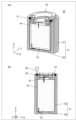
- FIG. 1(a) is a schematic perspective cross-sectional view showing a cross-sectional structure of a battery according to Embodiment 1 of the present disclosure
- FIG. 1(b) is a part of the cross-sectional structure of the sealing member in FIG. is a partial cross-sectional view showing (a) to (c) are schematic partial cross-sectional views showing each step in the method of manufacturing the sealing member.
- (a) is a schematic perspective cross-sectional view showing a cross-sectional structure of a battery according to Modification 1 of Embodiment 1 of the present disclosure, and (b) is a case where the cross-sectional view of (a) is the ZX plane; It is a schematic cross-sectional view showing the.
- (a) is a schematic perspective cross-sectional view showing a cross-sectional structure of a battery according to Modification 2 of Embodiment 1 of the present disclosure, and (b) is a case where the cross-sectional view of (a) is the ZX plane; It is a schematic cross-sectional view showing the.
- (a) is a schematic perspective cross-sectional view showing a cross-sectional structure of a battery according to Modification 3 of Embodiment 1 of the present disclosure, and (b) is a case where the cross-sectional view of (a) is the ZX plane; It is a schematic cross-sectional view showing the.
- the present inventors have investigated a sealed battery that can seal the battery can without forming a crimped portion by joining the battery can and the sealing member, for example, by welding. bottom.
- the sealing member of the battery is generally a gasket made of resin (such as polypropylene) crimped with a metal member having a thickness of several 100 ⁇ m.
- resin such as polypropylene
- the temperature rise of the gasket will be described in detail.
- the temperature of the welded portion where the end on the opening edge side and the end on the outer peripheral side of the sealing member are butt-welded is the melting point of the metal material used for the battery can and the sealing member (for example, the melting point of iron is about 1500° C.).
- the gasket is crimped with a metal member having a thickness of several hundred ⁇ m, and the distance to the welded portion is also several hundred ⁇ m.
- the gasket is made of polypropylene, the melting point is 140° C., which is about 1400° C. different from that of the welded portion, so the gasket may melt during welding.
- the sealing member is formed by caulking the gasket with a metal member having a thickness of several 100 ⁇ m.
- a metal member having a thickness of several 100 ⁇ m In the caulking process, two kinds of metal parts having different potentials in a battery are insulated and hermetically sealed. Therefore, resin is crushed by a metal member and hermetically sealed by the repulsive force of the resin. If the gasket melts due to welding, the gasket melts while being crushed by the metal member, so the melted resin may squirt out, preventing the resin from maintaining a sealed state and reducing the airtightness. There is If the airtightness of the sealing member deteriorates, the safety of the battery also deteriorates, so it is necessary to avoid melting of the gasket in sealing the battery.
- the present inventors examined the following battery according to the present disclosure as a battery capable of solving such problems.
- a battery in one aspect of the present disclosure includes a metal battery can, an electrode body, an electrolytic solution, and a sealing member.
- the battery can has a cylindrical portion with an opening edge at one end and a bottom closing the other end of the cylindrical portion.
- An electrode body is accommodated in the battery can.
- the battery can is filled with an electrolyte.
- the sealing member seals the opening edge of the cylindrical portion of the battery can.
- the sealing member is fixed such that the outer peripheral surface of the sealing member faces the inner peripheral surface of the opening edge. Specifically, a portion of the inner peripheral surface of the opening edge and a portion of the outer peripheral surface of the sealing member are fixed by being joined by the fusion zone. Further, an intermediate member made of a metal material having a melting point equal to or lower than the melting point of the metal material of the sealing member is provided on the upper surface of the sealing member.
- the intermediate member can suppress heat conduction to the gasket portion when the battery can and the sealing member are joined.
- the temperature rise of the gasket portion due to the heat transferred to the gasket portion side of the sealing member is suppressed.
- the temperature rise of the gasket portion due to the heat transferred to the gasket portion side of the sealing member is suppressed.
- the melting of the gasket portion can be suppressed. Therefore, it is possible to reduce airtightness failure of the sealing member due to heat during welding.
- the battery can can be sealed by welding, and the sealing member can be fixed to the battery can.
- annular protrusion also referred to as a diameter-reduced portion
- reduction can be achieved.
- the volume of the battery can can be reduced, and the energy density of the battery, which is the ratio of the battery energy to the volume of the battery can, is improved.
- a battery according to a first aspect includes a metal battery can having a cylindrical portion having an opening edge at one end and a bottom closing the other end of the cylindrical portion, and and a sealing member that is joined to the opening edge of the battery can and seals the opening of the opening edge.
- a ring portion and an intermediate member bonded to the top surface of the ring portion are included.
- the intermediate member may be made of a metal material having a melting point lower than that of the metal of the disc portion and the metal of the battery can.
- the sealing member may have the ring portion and the intermediate member joined by the first melting portion.
- a battery according to a fourth aspect is the battery according to the third aspect, wherein the first melted portion has a melted area on a surface where the ring portion and the gasket portion are in contact with each other at an interface between the ring portion and the intermediate member. It may be larger than the melting area.
- a battery according to a fifth aspect is the battery according to the third or fourth aspect, wherein the first fusion zone protrudes in the direction of the gasket part on the surface where the ring part and the gasket part are in contact. good.
- a battery according to a sixth aspect is the battery in any one of the first to fifth aspects, wherein the ring portion has a recess on an upper surface, and the intermediate member is joined to the ring portion so as to engage with the recess.
- the intermediate member may have an annular shape, and the diameter of the annular shape may be the same as the diameter of the battery can. .
- the thickness of the outer periphery of the intermediate member in the annular shape may be thinner than the thickness of the inner periphery.
- FIG. 1(a) is a schematic perspective cross-sectional view showing the cross-sectional structure of battery 10 according to Embodiment 1.
- FIG. FIG. 1(b) shows a cross-sectional view of the battery 10 according to Embodiment 1.
- the opening side of the battery can 11 is defined as the Z direction
- the direction perpendicular to the Z axis in the cross section including the Z axis is defined as the X direction
- the direction perpendicular to the Z and X axes is defined as the Y direction.
- the battery 10 includes a battery can 11 , a sealing member 12 , an electrolytic solution 14 and an electrode body 15 .
- the battery can 11 has a cylindrical portion 31 having an opening edge at one end and a bottom portion 32 closing the other end of the cylindrical portion 31 .
- the cylindrical portion 31 is, for example, a cylindrical portion
- the battery can 11 is a bottomed container having a cylindrical shape with an open upper end in the drawing.
- the battery can 11 is made of metal.
- the battery can 11 accommodates an electrode assembly 15 , and the battery can 11 is filled with an electrolytic solution 14 .
- the battery can 11 is sealed with a sealing member 12 .
- the space in which the electrode body 15 and the electrolytic solution 14 are housed inside the battery can 11 is a sealed space. Therefore, battery 10 according to Embodiment 1 is a sealed battery.
- the sealing member 12 forms a positive electrode portion by crimping a disc portion to the central portion through a gasket portion.
- the sealing member 12 has a disk shape, and has a shape in which the central portion is raised above the outer peripheral portion due to the presence of an intermediate member 20 to be described later.
- the sealing member 12 has an outer peripheral surface arranged to face the inner peripheral surface of the battery can 11 . The sealing member 12 is inserted into the battery can 11 so that the height of the upper end of the sealing member 12 in the drawing and the height of the upper end of the battery can 11 in the drawing are approximately the same.
- the electrode body 15 emits or absorbs electrons or ions into the battery can 11 depending on its material.
- the electrode body 15 has two types, a positive electrode and a negative electrode, and has a three-layer structure in which a separator is sandwiched between them to block the movement of electrons or ions.
- the electrode body 15 has positive and negative electrode tab portions through which electrons or ions flow respectively for the positive electrode and the negative electrode, but they are omitted in this drawing.
- the electrolytic solution 14 is a medium through which electrons or ions emitted from the electrode body 15 can move.
- the battery 10 of the present disclosure is manufactured through the following steps. (1) First, the electrode body 15 is inserted into the battery can 11, and the electrolytic solution 14 is injected. (2) Subsequently, as shown in FIG. 1(b), the battery is assembled so that the upper end of the inner peripheral surface of the battery can 11 and the upper end of the outer peripheral surface of the sealing member 12 are substantially aligned with each other. A sealing member 12 is inserted into the can 11 . (3) Subsequently, for example, the battery can 11 and part of the sealing member 12 are irradiated with a melting laser 16 . Also, the melting laser 16 is scanned along the circumferential direction of the outer periphery of the sealing member 12 .
- the battery 10 of the present disclosure is manufactured through the above steps.
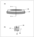
- FIG. 2A is a schematic perspective view showing the appearance of the sealing member 12 in the battery 10 according to Embodiment 1
- FIG. 2B is a cross section of the sealing member 12 in FIG.
- FIG. 4 is a schematic partial cross-sectional view showing part of the structure
- the sealing member 12 includes an intermediate member 20, a ring portion 21, a gasket portion 22, and a disk portion 23.
- the ring portion 21 and the disk portion 23 are made of a metal material
- the gasket portion 22 is made of a resin material.
- the sealing member 12 is ring-shaped, for example.
- the disc portion 23 is crimped by the ring portion 21 through the gasket portion 22 . That is, as shown in FIG. 2B, the ring portion 21 has a disk portion 23 crimped to the central portion of the ring portion 21 via a gasket portion 22 .
- the sealing member 12 is electrically insulated from the disc portion 23 by the gasket portion 22 .
- An intermediate member 20 made of a metal material having a melting point lower than that of other metal materials of the sealing member is provided on the upper surface of the sealing member 12 .
- the metal material forming the ring portion 21 is the same as that of the battery can 11 .
- the metal material forming the intermediate member 20 is made of a metal material having a melting point lower than that of the metal material forming the ring portion 21 .
- the intermediate member 20 can suppress heat conduction to the gasket portion 22 when the battery can 11 and the sealing member 12 are joined.
- the intermediate member 20 and the ring portion 21 are superimposed and heated from the ring portion 21 side by, for example, a laser beam for bonding. Specifically, the intermediate member 20 is attached to the upper surface side of the ring portion 21 and welding is performed from the lower surface side with a welding laser 25 to form a dissimilar material fusion portion 26 .
- the melting point of the ring portion 21 is higher than the melting point of the intermediate member 20 as described above, the high melting point metal material side is heated. As a result, the amount of heat transmitted to the low melting point side can be suppressed, so the generation of intermetallic compounds due to mixing with the low melting point metal material can be suppressed, and the bonding strength can be maintained.
- the relationship between the surface fusion width 27 and the interface fusion width 28 at the interface between the sealing member 12 and the intermediate member 20 is surface fusion width 27 > interface fusion width 28 .
- the irradiation conditions are a wavelength of 1070 nm, an output of 250 W, a scanning speed of 500 mm/s, and a spot diameter of 20 ⁇ m. becomes.
- the dissimilar material melted portion 26 is in a state of protruding by several tens of ⁇ m in the melting direction compared to the surface before welding due to a change in crystal structure due to heat during welding.
- the sealing member 12 of the battery 10 is manufactured by crimping the disc portion 23 with the ring portion 21 via the gasket portion 22 .
- the sealing member 12 shown in FIG. 1 has a shape in which the central portion protrudes higher than the outer peripheral portion due to the presence of the intermediate member 20 . That is, battery 10 has a convex portion on the upper surface. However, it is desirable that the cell have flat surfaces.
- FIG. 4(a) is a schematic perspective cross-sectional view showing a cross-sectional structure of a battery 10a according to Modification 1 of Embodiment 1.
- FIG. 4(b) is a schematic cross-sectional view showing the case where the cross-sectional view of (a) is the ZX plane.
- the battery 10a includes a sealing member 12a.
- the sealing member 12a is manufactured so that the upper surface of the ring portion has unevenness, and the intermediate member 20 is fitted into the concave portion of the ring portion.
- the upper surface of the sealing member 12a can be flattened, so that the shape stability of the battery is high.
- the caulking structure of the sealing member 12a is complicated, and the cost is increased.
- FIG. 5(a) is a schematic perspective cross-sectional view showing a cross-sectional structure of a battery 10b according to Modification 2 of Embodiment 1
- FIG. 5(b) is a cross-sectional view of (a) taken along the ZX plane. It is a schematic sectional drawing which shows a certain case.
- the battery 10b includes a sealing member 12b.
- the sealing member 12b is manufactured so that the ring portion 21 has the same shape as in FIG.
- Modification 2 it is possible to achieve both simplification of the caulking structure and flattening of the upper surface of the sealing member 12b. Further, the intermediate member 20a stops at the edge of the battery can 11 when the sealing member 12b is inserted, thereby facilitating positioning. On the other hand, as a demerit, since the melted portion 18 of the same kind of material, which is the welded portion between the battery can 11 and the sealing member 12b in FIG. It is necessary.
- the intermediate member and the battery can do not necessarily need to be joined, and the sealing member 12b and the battery can only need to be joined.
- FIG. 6(a) is a schematic perspective cross-sectional view showing the cross-sectional structure of a battery 10c according to Modification 3 of Embodiment 1, and (b) shows the cross-sectional view of (a) taken along the ZX plane. It is a schematic cross-sectional view showing the.
- the battery 10c includes a sealing member 12c.
- the ring portion 21 of the sealing member 12c has the same shape as that of FIG. Manufactured in As a result, the same merits as those of the battery 10b can be obtained.
- the sealing member 12 is used to improve the melting efficiency because the laser-irradiated portion of the intermediate member 20b becomes thin when joining the ring portion 21, the intermediate member 20b, and the battery can 11 together. can be improved more.
- the intermediate member and the battery can are not necessarily joined, and the sealing member 12c and the battery can 11 only need to be joined.
- the shape of the battery can 11 is cylindrical in the present disclosure, the shape of the battery can 11 is not limited to this. For example, it may be an elliptical cylinder or a polygonal cylinder.
- the shape of the sealing member 12 is a disk shape in which the outer peripheral portion protrudes upward from the central portion, but the shape of the sealing member 12 is not limited to such a shape, and the outer peripheral surface of the sealing member 12 is a battery can. Any shape may be used as long as it can be inserted inside the opening edge so as to face the inner peripheral surface of the opening edge of 11 and can close the opening edge 17 .
- the configuration of the present disclosure may work effectively even when a battery module is manufactured by electrically connecting a plurality of batteries with current collector plates or the like.
- the battery module has a configuration in which the positive electrode of the battery is electrically connected to the sealing member and the negative electrode is electrically connected to the bottom of the can, so current collector plates are required above and below the battery.
- Japanese Patent Application Laid-Open No. 2021-93381 there are some efforts to reduce the required volume of the battery module and improve the volumetric energy density by collecting the current collectors on the upper side.
- An intermetallic compound layer is generally generated when metals with different melting points are mixed together.
- a metal material is joined to a sealing member, for example, when welding is performed, generally, the metal material and the sealing member are brought into close contact with each other, and heat is applied from the metal material side for welding.
- heat is applied from the low-melting-point metal side, most of the low-melting-point metal first melts during welding.
- the high-melting-point metal material melts with a time lag, it mixes with the metal on the low-melting-point side, so an intermetallic compound is generated and the joint strength of the weld is reduced.
- the present configuration proposes a construction method in which dissimilar materials are joined in the process of producing the sealing member.
- the battery according to the present disclosure can be used for various can-type batteries, and is useful for application as a power source for mobile devices, hybrid vehicles, electric vehicles, and the like.
Landscapes
- Chemical & Material Sciences (AREA)
- Chemical Kinetics & Catalysis (AREA)
- Electrochemistry (AREA)
- General Chemical & Material Sciences (AREA)
- Inorganic Chemistry (AREA)
- Sealing Battery Cases Or Jackets (AREA)
Abstract
Description
従来における電池の封口方法では、かしめ部を形成した結果、封口部材近傍における電池の長手方向の寸法が増加し、電池のエネルギ密度は低下する。そこで、本発明者らは、従来の課題を解決するため、電池缶と封口部材とを、例えば、溶接により接合することで、かしめ部を形成せずに電池缶を封口できる密閉型電池を検討した。
以下、本開示の電池について、図面を参照しながら具体的に説明する。
電池缶11は、一方の端部に開口縁部を有する筒部31、および、筒部31の他方の端部を閉じる底部32を有する。実施の形態1において、筒部31は、例えば、円筒部であり、電池缶11は、図面上の上端が開口した円筒形状を有する有底容器である。電池缶11は金属製である。電池缶11には電極体15が収容され、電池缶11内に電解液14が充填されている。電池缶11は、封口部材12によって封口されている。電池缶11の内部における電極体15と電解液14とが収容された空間は、密閉された空間となっている。よって、実施の形態1に係る電池10は密閉型電池である。
封口部材12は、ガスケット部を介して中心部に円盤部をかしめることで、正極部を形成している。封口部材12は、円盤形状を有し、後述する中間部材20があることで、外周部分よりも中央部分が上方に隆起した形状を有する。封口部材12は、電池缶11の内周面と対向するように配置された外周面を有する。封口部材12の図面上の上端の高さと電池缶11の図面上の上端の高さとがおおむね一致するように、封口部材12は電池缶11内に挿入されている。
電極体15は、その材質によって、電池缶11内に電子またはイオンを放出または吸収させる。電極体15は正極と負極との2種類を有し、その間に電子またはイオンの移動を遮るセパレータを挟んだ3層構造を有する。また、電極体15には正極、負極それぞれに対して電子、またはイオンの流れる正極・負極タブ部が存在しているが、本図面では割愛する。
電解液14は、電極体15より放出された電子またはイオンが移動できる媒体である。
本開示の電池10は、次の工程を経て製造される。
(1)まず、電池缶11に電極体15を挿入し、電解液14が注入される。
(2)続いて、図1(b)に示すように、電池缶11の内周面の図面上の上端と、封口部材12の外周面の図面上の上端とがおおむね一致するように、電池缶11に封口部材12を挿入する。
(3)続いて、例えば、溶解用レーザ16を用いて、電池缶11と封口部材12の一部とに照射する。また、封口部材12の外周の周方向に沿って、溶解用レーザ16を走査させる。この照射によって、同種材溶融部18が形成され、封口部材12の外周は、筒部31の内周に接合される。その結果、電池缶11は封口され、封口部材12は電池缶11に固定される。
次に、電池缶11の封口部材12の詳細について、図2を用いて説明する。図2(a)は、実施の形態1に係る電池10における封口部材12の外観を示す概略斜視図であり、(b)は、(a)の封口部材12のA-Aの方向からみた断面構造の一部を示す概略部分断面図である。
次に、封口部材12の製造方法について、図3を用いて説明する。
また、本実施の形態1の変形例1に係る封口部材を以下のように製造することができる。図4(a)は、実施の形態1の変形例1に係る電池10aの断面構造を示す概略斜視断面図である。図4(b)は、(a)の断面図がZ-X面である場合を示す概略断面図である。
また、本実施の形態1の変形例2に係る封口部材12bをさらに以下のように製造してもよい。図5(a)は、実施の形態1の変形例2に係る電池10bの断面構造を示す概略斜視断面図であり、図5(b)は、(a)の断面図がZ-X面である場合を示す概略断面図である。
さらに、本実施の形態1の変形例3に係る封口部材を以下のように製造してもよい。図6(a)は、実施の形態1の変形例3に係る電池10cの断面構造を示す概略斜視断面図であり、(b)は、(a)の断面図がZ-X面である場合を示す概略断面図である。
11 電池缶
12、12a、12b、12c 封口部材
14 電解液
15 電極体
16 溶解用レーザ
17 開口縁部
18 同種材溶融部
20、20a、20b 中間部材
21 リング部
22 ガスケット部
23 円盤部
25 溶接用レーザ
26 異種材溶融部
27 表面溶融幅
28 界面溶融幅
29 ガスケット圧縮長さ
31 筒部
32 底部
Claims (8)
- 一方の端部に開口縁部を有する筒部、および、前記筒部の他方の端部を閉じる底部を有する金属製の電池缶と、
前記筒部の内部に収容された電極体と、
前記電池缶の前記開口縁部と接合され、前記開口縁部の開口を封口する封口部材と、を備え、
前記封口部材は、
ガスケット部と、
金属製の円盤部と、
前記ガスケット部を介して中心部に前記円盤部をかしめたリング部と、
前記リング部の上面に接合された中間部材と、を含む、
電池。 - 前記中間部材は、前記円盤部の金属および前記電池缶の金属の融点より低い融点を持つ金属材料で構成されている、
請求項1に記載の電池。 - 前記封口部材は、前記リング部と前記中間部材とを第一溶融部により接合されている、
請求項1または2に記載の電池。 - 前記第一溶融部は、前記リング部と前記ガスケット部との接する面における溶融面積が、前記リング部と前記中間部材との界面における溶融面積より大きい、
請求項3に記載の電池。 - 前記第一溶融部は、前記リング部と前記ガスケット部との接する面において、前記ガスケット部の方向に隆起している、
請求項3または4に記載の電池。 - 前記リング部は、上面に凹部を有し、前記中間部材は前記凹部に係合するよう前記リング部と接合される、
請求項1から5のいずれか1項に記載の電池。 - 前記中間部材は円環形状であり、前記円環形状の直径は前記電池缶の直径と同じである、
請求項1から5のいずれか1項に記載の電池。 - 前記中間部材は、前記円環形状における外周の厚さが内周の厚さより薄い、
請求項7に記載の電池。
Priority Applications (4)
| Application Number | Priority Date | Filing Date | Title |
|---|---|---|---|
| JP2023562126A JPWO2023089869A1 (ja) | 2021-11-16 | 2022-07-20 | |
| CN202280072719.9A CN118176618A (zh) | 2021-11-16 | 2022-07-20 | 电池 |
| EP22895158.8A EP4435941A4 (en) | 2021-11-16 | 2022-07-20 | BATTERY |
| US18/658,352 US20240304914A1 (en) | 2021-11-16 | 2024-05-08 | Battery |
Applications Claiming Priority (2)
| Application Number | Priority Date | Filing Date | Title |
|---|---|---|---|
| JP2021186345 | 2021-11-16 | ||
| JP2021-186345 | 2021-11-16 |
Related Child Applications (1)
| Application Number | Title | Priority Date | Filing Date |
|---|---|---|---|
| US18/658,352 Continuation US20240304914A1 (en) | 2021-11-16 | 2024-05-08 | Battery |
Publications (1)
| Publication Number | Publication Date |
|---|---|
| WO2023089869A1 true WO2023089869A1 (ja) | 2023-05-25 |
Family
ID=86396585
Family Applications (1)
| Application Number | Title | Priority Date | Filing Date |
|---|---|---|---|
| PCT/JP2022/028253 Ceased WO2023089869A1 (ja) | 2021-11-16 | 2022-07-20 | 電池 |
Country Status (5)
| Country | Link |
|---|---|
| US (1) | US20240304914A1 (ja) |
| EP (1) | EP4435941A4 (ja) |
| JP (1) | JPWO2023089869A1 (ja) |
| CN (1) | CN118176618A (ja) |
| WO (1) | WO2023089869A1 (ja) |
Citations (6)
| Publication number | Priority date | Publication date | Assignee | Title |
|---|---|---|---|---|
| JPH07105933A (ja) | 1993-10-06 | 1995-04-21 | Hitachi Maxell Ltd | 防爆形密閉電池 |
| JPH07183011A (ja) * | 1993-12-22 | 1995-07-21 | Furukawa Battery Co Ltd:The | 角形密閉電池の製造方法 |
| JPH117922A (ja) * | 1997-06-18 | 1999-01-12 | Mitsubishi Cable Ind Ltd | 密閉型電池の密閉構造 |
| JP2013542567A (ja) * | 2010-12-07 | 2013-11-21 | エルジー・ケム・リミテッド | キャップアッセンブリー及びこれを用いた二次電池 |
| JP2015099681A (ja) * | 2013-11-19 | 2015-05-28 | 日立マクセル株式会社 | 密閉型電池 |
| JP2021093381A (ja) | 2017-02-23 | 2021-06-17 | パナソニックIpマネジメント株式会社 | 電池モジュール |
Family Cites Families (2)
| Publication number | Priority date | Publication date | Assignee | Title |
|---|---|---|---|---|
| JPS60249241A (ja) * | 1984-05-24 | 1985-12-09 | Matsushita Electric Ind Co Ltd | 密閉形電池 |
| CN115004461B (zh) * | 2020-02-28 | 2024-08-20 | 松下知识产权经营株式会社 | 蓄电设备 |
-
2022
- 2022-07-20 WO PCT/JP2022/028253 patent/WO2023089869A1/ja not_active Ceased
- 2022-07-20 CN CN202280072719.9A patent/CN118176618A/zh active Pending
- 2022-07-20 EP EP22895158.8A patent/EP4435941A4/en active Pending
- 2022-07-20 JP JP2023562126A patent/JPWO2023089869A1/ja active Pending
-
2024
- 2024-05-08 US US18/658,352 patent/US20240304914A1/en active Pending
Patent Citations (6)
| Publication number | Priority date | Publication date | Assignee | Title |
|---|---|---|---|---|
| JPH07105933A (ja) | 1993-10-06 | 1995-04-21 | Hitachi Maxell Ltd | 防爆形密閉電池 |
| JPH07183011A (ja) * | 1993-12-22 | 1995-07-21 | Furukawa Battery Co Ltd:The | 角形密閉電池の製造方法 |
| JPH117922A (ja) * | 1997-06-18 | 1999-01-12 | Mitsubishi Cable Ind Ltd | 密閉型電池の密閉構造 |
| JP2013542567A (ja) * | 2010-12-07 | 2013-11-21 | エルジー・ケム・リミテッド | キャップアッセンブリー及びこれを用いた二次電池 |
| JP2015099681A (ja) * | 2013-11-19 | 2015-05-28 | 日立マクセル株式会社 | 密閉型電池 |
| JP2021093381A (ja) | 2017-02-23 | 2021-06-17 | パナソニックIpマネジメント株式会社 | 電池モジュール |
Non-Patent Citations (1)
| Title |
|---|
| See also references of EP4435941A4 |
Also Published As
| Publication number | Publication date |
|---|---|
| JPWO2023089869A1 (ja) | 2023-05-25 |
| CN118176618A (zh) | 2024-06-11 |
| EP4435941A1 (en) | 2024-09-25 |
| US20240304914A1 (en) | 2024-09-12 |
| EP4435941A4 (en) | 2025-02-26 |
Similar Documents
| Publication | Publication Date | Title |
|---|---|---|
| JP5481178B2 (ja) | 組電池および単電池 | |
| JP6093874B2 (ja) | 角形二次電池 | |
| CN105849939B (zh) | 二次电池 | |
| JP6427460B2 (ja) | 角形二次電池 | |
| JP5862682B2 (ja) | 電池容器、及びその製造方法 | |
| US20120248076A1 (en) | Laser welding method and battery made by the same | |
| KR20100087374A (ko) | 용접 구조체 제조 방법 및 전지 제조 방법 | |
| KR20090032997A (ko) | 밀폐전지 및 그 제조방법 | |
| JP2016207510A (ja) | 角形二次電池 | |
| JP2010093178A (ja) | 電気化学キャパシタ及びその製造方法 | |
| US20160254565A1 (en) | Second battery and method of producing the same | |
| CN115642373A (zh) | 二次电池 | |
| US20210167455A1 (en) | Battery module and method for manufacturing same | |
| JP2005216825A (ja) | 角形電池とその製造方法 | |
| KR20240045988A (ko) | 전지 캔의 캡 조립 구조 및 조립 방법 | |
| JP2005183360A (ja) | 角形電池とその製造方法 | |
| US20060127759A1 (en) | Lactobacillus casei bd-II strain and used to reduce blood | |
| US20240413440A1 (en) | Seam Welding Structure of Battery Can, Current Collecting Plate, and Cap and Battery Cell Using the Same | |
| WO2010041461A1 (ja) | 蓄電装置と、蓄電装置を備えた蓄電装置ユニット、及び蓄電装置の製造方法 | |
| KR102610475B1 (ko) | 이차전지 캡 어셈블리의 이종 금속 레이저 용접방법 | |
| JP2010010166A (ja) | コンデンサの製造方法 | |
| KR20240144310A (ko) | 에너지 저장용 배터리의 제조방법 | |
| WO2023089869A1 (ja) | 電池 | |
| CN115708252A (zh) | 电池组及其制造方法 | |
| JP2023015619A (ja) | 二次電池、その電極部品及び組電池 |
Legal Events
| Date | Code | Title | Description |
|---|---|---|---|
| 121 | Ep: the epo has been informed by wipo that ep was designated in this application |
Ref document number: 22895158 Country of ref document: EP Kind code of ref document: A1 |
|
| WWE | Wipo information: entry into national phase |
Ref document number: 202280072719.9 Country of ref document: CN |
|
| ENP | Entry into the national phase |
Ref document number: 2023562126 Country of ref document: JP Kind code of ref document: A |
|
| WWE | Wipo information: entry into national phase |
Ref document number: 2022895158 Country of ref document: EP |
|
| ENP | Entry into the national phase |
Ref document number: 2022895158 Country of ref document: EP Effective date: 20240617 |