WO2023090003A1 - ヘルメット - Google Patents
ヘルメット Download PDFInfo
- Publication number
- WO2023090003A1 WO2023090003A1 PCT/JP2022/038226 JP2022038226W WO2023090003A1 WO 2023090003 A1 WO2023090003 A1 WO 2023090003A1 JP 2022038226 W JP2022038226 W JP 2022038226W WO 2023090003 A1 WO2023090003 A1 WO 2023090003A1
- Authority
- WO
- WIPO (PCT)
- Prior art keywords
- wing
- shell
- gap
- flap
- rear side
- Prior art date
- Legal status (The legal status is an assumption and is not a legal conclusion. Google has not performed a legal analysis and makes no representation as to the accuracy of the status listed.)
- Ceased
Links
Images







Classifications
-
- A—HUMAN NECESSITIES
- A42—HEADWEAR
- A42B—HATS; HEAD COVERINGS
- A42B3/00—Helmets; Helmet covers ; Other protective head coverings
- A42B3/04—Parts, details or accessories of helmets
- A42B3/28—Ventilating arrangements
-
- A—HUMAN NECESSITIES
- A42—HEADWEAR
- A42B—HATS; HEAD COVERINGS
- A42B3/00—Helmets; Helmet covers ; Other protective head coverings
- A42B3/04—Parts, details or accessories of helmets
- A42B3/0493—Aerodynamic helmets; Air guiding means therefor
-
- A—HUMAN NECESSITIES
- A42—HEADWEAR
- A42B—HATS; HEAD COVERINGS
- A42B3/00—Helmets; Helmet covers ; Other protective head coverings
- A42B3/04—Parts, details or accessories of helmets
- A42B3/28—Ventilating arrangements
- A42B3/281—Air ducting systems
- A42B3/283—Air inlets or outlets, with or without closure shutters
Definitions
- the present disclosure relates to a helmet provided with an airflow control section on the outer surface of the cap body.
- the helmet worn by the driver generates an air current that flows along the outer surface of the cap and an air current that separates from the outer surface of the cap.
- the difference in airflow around the helmet makes a big difference in the comfort of the driver.
- the airflow that flows from the front of the helmet through the inside of the helmet to the outside of the helmet enhances the ventilation performance inside the helmet (see Patent Documents 1 to 3, for example).
- Suppression of airflow fluctuations around the helmet reduces noise such as wind noise and enhances quiet performance.
- Suppression of turbulence in the airflow separated from the helmet enhances the stability performance of the driving posture during straight running (see Patent Document 4, for example).
- the change in the external shape of the outer surface of the cap creates a new airflow around the helmet that enhances the wearing comfort.
- the cap itself which is required to have high mechanical strength, high impact resistance, and high penetration resistance, limits the addition of a new structure to improve wearing comfort.
- a helmet includes a cap body and an airflow control section attached to the outer surface of the cap body.
- the airflow control section has two wing sections that sandwich the rear portion of the outer surface of the cap body in the left-right direction.
- Each of the two wing portions is connected to the rear side portion so as to extend from a portion of the rear side portion in the outer surface of the cap body, and is opposed to the wing portion in the rear side portion.
- a gap is defined between the rear side portion and the wing portion to penetrate from the front to the rear, and the air entering the gap from the front is directed downward to the rear. configured to emit
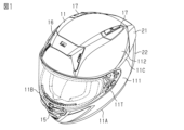
- FIG. 1 is a perspective view showing the front upper left side structure of the helmet.
- FIG. 2 is a perspective view showing the rear lower right side structure of the helmet.
- FIG. 3 is a rear view showing the rear structure of the helmet.
- FIG. 4 is an exploded left side view showing the rear spoiler and shell separately.
- FIG. 5 is a perspective view showing the perspective structure of the fixing member.
- FIG. 6 is a top view showing the top structure of the rear spoiler.
- FIG. 7 is a front view of the lower surface structure of the rear spoiler as seen from the front.
- FIG. 8 is a perspective view of the current plate of the rear spoiler as seen from the front upper side.
- FIG. 9 is a perspective view of the shell and rear spoiler viewed from the front upper side.
- FIG. 1 is a perspective view showing the front upper left side structure of the helmet.
- FIG. 2 is a perspective view showing the rear lower right side structure of the helmet.
- FIG. 3 is a rear view showing the rear structure of the
- FIG. 10 is a perspective view of the shell and rear spoiler as seen from the rear lower side.
- FIG. 11 is a side view showing the outer surface structure of the rear flap.
- FIG. 12 is a side view showing the inner surface structure of the rear flap.
- FIG. 13 is a perspective view of the shell and rear flap as seen from the rear lower side.
- FIG. 14 is a perspective view of each airflow control member viewed from the front left side.
- FIG. 15 is a partial cross-sectional view showing the shell and each airflow control member.
- FIG. 16 is a partially enlarged view showing the shell and each airflow control member.
- FIG. 17 is a diagram showing a fluid analysis result of running wind around the helmet.
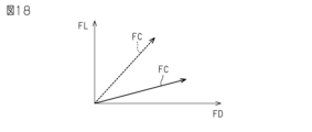
- FIG. 18 is a graph showing the force components that the shell receives.
- the virtual vertical plane passing through the center of the helmet in the left-right direction is the left-right center plane.
- the left side of the center plane is also called the left side
- the right side of the center plane is called the right side.
- the virtual vertical plane passing through the center of the helmet in the front-back direction is the front-back center plane.
- the front side of the front-rear center plane is also simply referred to as the front side
- the back side of the front-rear center plane is simply referred to as the rear side.
- the helmet includes a shell 11, which is an example of a cap body, and a rear spoiler 21, which is an example of a first airflow control member.
- the helmet may comprise two rear flaps 22.
- Each of the two rear flaps 22 is an example of a second airflow control member.
- the rear spoiler 21 and the two rear flaps 22 may constitute an airflow control section.
- Shell 11 may comprise front lower inlet 15 , front upper inlet 16 and top outlet 17 .
- the shell 11 is a resin molding that constitutes the outermost shell of the helmet.
- the shell 11 has a hemispherical shape that is substantially symmetrical with respect to the left-right central plane.
- the shell 11 has a hemispherical shape that protrudes slightly toward the rear.
- An example of the material forming the shell 11 is one selected from the group consisting of acrylonitrile-butadiene-styrene copolymer, polycarbonate, and thermosetting resin impregnated with reinforcing fibers.
- the lower end of the shell 11 is provided with a mounting opening 11A that is an opening.
- the mounting opening 11 ⁇ /b>A is an opening for the user to insert the head inside the shell 11 and for the wearer to pull out the head from the inside of the shell 11 .
- the mounting opening 11A is an opening for arranging the shock absorber 11B inside the shell 11 .
- the front portion of the shell 11 is provided with a shielding opening 11T that is an opening.
- the shield opening 11T is an opening for the wearer to visually recognize the forward environment from the inside of the shell 11 .
- the front lower inlet 15 is located at the lower front portion of the shell 11 .
- the front lower inlet 15 introduces running wind from the front lower side of the shell 11 toward the inside of the shell 11 .
- Running wind introduced into the interior of the shell 11 from the front lower inlet 15 is blown to interior members such as the shock absorber 11B housed inside the shell 11 .
- the running wind blown to the interior member suppresses heat build-up in the interior member.
- the front upper inlet 16 is located in the front upper part of the shell 11 .
- the front upper inlet 16 introduces running wind from the front upper side of the shell 11 toward the inside of the shell 11 .
- Running wind introduced into the shell 11 from the front upper inlet 16 flows through the vicinity of the top of the head inside the shell 11 and is discharged from the two top outlets 17 .
- One of the two top outlets 17 is located on the right side of the rear upper side of the shell 11 .
- the other of the two top outlets 17 is located on the left side of the rear upper side of the shell 11 .
- Running wind flowing from the front upper inlet 16 to the two top outlets 17 ventilates the inside of the shell 11 .
- the left portion of the outer surface of the shell 11 comprises a shell lower side 111 and a shell upper side 112 .
- the right portion of the outer surface of shell 11 comprises a shell lower surface 111 and a shell upper surface 112 .
- the shell 11 may be provided with an inflow guide surface 11C at the boundary between the shell lower surface 111 and the shell upper surface 112 .
- the shell 11 may include one inflow guide surface 11C on each of the left and right portions.
- the inflow guide surface 11C is a curved surface that rises small and gently in the outer surface of the shell 11.
- the inflow guide surface 11 ⁇ /b>C has an arc shape that follows the outer surface of the shell 11 from the front side of the shell 11 toward the upper rear side of the shell 11 .
- the inflow guide surface 11C continues from the rear end of the shield opening 11T toward the rear portion 113 (see FIG. 2) of the shell 11 where the rear spoiler 21 is located.
- the amount of swelling of the inflow guide surface 11C gradually increases from the front end to the rear end of the inflow guide surface 11C.
- a surface that rises in a smooth surface, such as the inflow guide surface 11C slows down the flow of air in front of the raised surface and increases the flow behind the raised surface.
- the inflow guide surface 11C makes the direction of the airflow follow the direction in which the inflow guide surfaces 11C are connected in the airflow flowing along the outer surface of the shell 11, and the direction of the airflow flowing along the inflow guide surface 11C.
- the outer surface of the shell 11 has a rear portion 113 located rearward of the front-rear center plane.
- a rear end of the inflow guide surface 11C constitutes a rear portion 113 in the outer surface of the shell 11.
- the rear spoiler 21 protrudes rearward from the rear portion 113 of the shell 11 so as to be continuous with the rear portion 113 at the upper end of the rear portion 113 of the shell 11 .
- the rear spoiler 21 protrudes rearward from the shell 11 from the rear portion 113 so as to be continuous with the rear end of the inflow guide surface 11C.
- the rear spoiler 21 is arranged on the rear side portion 113 of the shell 11 from the right side portion of the shell 11 to the left side portion of the shell 11 .
- Each of the two rear flaps 22 protrudes from the rear portion 113 toward the rear of the shell 11 so as to be continuous with the rear portion 113 at the lower portion of the rear portion 113 of the shell 11 .
- the two rear flaps 22 are arranged on the right side portion of the shell 11 and the left side portion of the shell 11, respectively.
- the rear spoiler 21 is located on the shell upper surface 112 in the rear portion 113 of the shell 11 .
- the rear spoiler 21 connects the rear ends of the two inflow guide surfaces 11C at the rear portion 113 of the shell 11 .
- the rear flap 22 is positioned on the shell lower side surface 111 and protrudes from the shell upper side surface 112 in the rear portion 113 of the shell 11 .
- the portion of the rear flap 22 that protrudes from the shell upper side surface 112 is the upper end portion of the rear flap 22 .
- the upper end of the rear flap 22 is located on the shell 11 side of the rear spoiler 21 and in the gap between the rear spoiler 21 and the shell 11 .
- the outer surface of the shell 11 is provided with wing connections 11D.
- the outer surface of shell 11 may comprise a flap connection 11E.
- the outer surface of shell 11 may be provided with fixing members 18 .
- the fixing member 18 is positioned at the rear upper end of the rear portion 113 of the shell 11 and is fixed to the shell 11 .
- the wing connecting portion 11D is located on the outer surface of the shell 11 behind the inflow guide surface 11C. Left-right ends of the rear spoiler 21 are joined to the wing connection portions 11D.
- the wing connection portion 11D is formed on the outer surface of the shell 11 by the thickness of the rear spoiler 21 so that the lateral end of the rear spoiler 21 and the inflow guide surface 11C are connected as a smooth curved surface. more recessed than
- the flap connecting portion 11E is positioned on the outer surface of the shell 11 at the rear end of the shell lower surface 111 and below the wing connecting portion 11D. An end portion of the rear flap 22 in the front-rear direction is joined to the flap connecting portion 11E.
- the flap connecting portion 11E is recessed from the wing connecting portion 11D by the thickness of the rear flap 22 on the shell lower side surface 111 so that the outer surface of the rear flap 22 and the shell lower side surface 111 are connected as a smooth curved surface. .
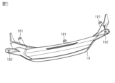
- the fixing member 18 has a bent plate shape extending laterally along the outer surface of the shell 11 .
- the fixed member 18 has a spoiler support portion 181 and a flap support portion 182 .
- the spoiler support portion 181 has a tubular shape extending toward the outer surface of the shell 11 .
- the spoiler support portion 181 is fitted into the fitting portion 21L (see FIG. 7) of the rear spoiler 21, thereby positioning the rear spoiler 21.
- the spoiler support portion 181 is screwed and fixed to the outer surface of the shell 11 so that the fixing member 18 presses the rear spoiler 21 against the outer surface of the shell 11 .
- the flap support part 182 has a plate shape with a fitting hole penetrating vertically.
- the fitting portion 22L (see FIG. 11) of the rear flap 22 is fitted into the flap support portion 182, thereby positioning the upper end portion of the rear flap 22 with respect to the outer surface of the shell 11 and the rear spoiler 21. .
- the rear spoiler 21 is a plate-like member extending in the left-right direction.
- the rear spoiler 21 has a spoiler portion 211 and two wing portions 212 .
- the two wing portions 212 are provided at both ends of the spoiler portion 211 in the left-right direction.
- the rear spoiler 21 may be a resin molding in which the spoiler portion 211 and the two wing portions 212 are integrated.
- An example of the material forming the rear spoiler 21 is one selected from the group consisting of acrylonitrile-butadiene-styrene copolymer, polycarbonate, and thermosetting resin impregnated with reinforcing fibers.
- the outer surface of the spoiler portion 211 has a curved surface that is smoothly connected in the left-right direction at the rear portion 113 of the shell 11 and smoothly extends rearward from the rear portion 113 of the shell 11 .
- the spoiler portion 211 has a spoiler front side edge 211E that is the front side edge of the spoiler portion 211 .
- the spoiler front edge 211 ⁇ /b>E has a gently curved shape that follows the upper edge of the rear portion 113 of the shell 11 .
- the spoiler portion 211 protrudes rearward from the rear portion 113 of the shell 11 so as to press the spoiler front side edge 211E against the rear portion 113 of the shell 11 and continue from the rear portion 113 .
- the inner surface of the spoiler portion 211 has one fitting portion 21L (see FIG. 7), and is positioned on the outer surface of the shell 11 by fitting the spoiler support portion 181 and the fitting portion 21L.
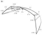
- the wing portion 212 has a curved shape that smoothly extends rearward along the rear end portion of the shell upper surface 112 and tapers rearward (see FIG. 8).
- the rear end of the shell upper surface 112 has a portion facing the wing portion 212 .
- the wing portion 212 has a curved shape that follows the portion facing the wing portion 212 (see FIG. 9).
- the wing portion 212 has a wing front side edge 212E as a lower end portion of the front side edge of the wing portion 212 .
- the wing portion 212 has a wing inlet end surface 212A positioned above the wing front side edge 212E as the upper end portion of the front end surface of the wing portion 212 .
- the wing front side edge 212E is smoothly connected to the rear end of the inflow guide surface 11C in the rear portion 113 of the shell 11 and has a linear shape that follows the rear end of the inflow guide surface 11C.
- the wing portion 212 protrudes from the inflow guide surface 11C toward the rear of the shell 11 so as to press the wing front side edge 212E against the rear end portion of the inflow guide surface 11C and continue from the inflow guide surface 11C.
- the wing inflow end surface 212A is an example of the front end surface of the wing portion 212.
- the wing inflow end surface 212A is an inclined surface that inclines toward the lower front side of the wing portion 212 (see FIG. 8).
- the wing inflow end surface 212A is inclined so that the front side portion of the wing inflow end surface 212A is positioned closer to the outer surface of the shell 11 .
- the wing inflow end face 212A has a wing gap 21H (see FIG. 9), which is a gap between the rear side portion 113 of the rear portion 113 of the shell upper side surface 112 and the wing portion 212, from the front to the rear. It is slanted so that it spreads out.
- each of the two wing portions 212 has one fitting portion 21L on its inner surface.
- Each of the two wing portions 212 has one first wing straightening vane 212B and one second wing straightening vane 212C on the inner surface.
- the first wing straightening vanes 212B and the second wing straightening vanes 212C are examples of straightening vanes provided in the wing portions 212, respectively.
- the wing part 212 has one fitting part 21L at the upper end of the wing part 212 .
- a lower portion of the wing portion 212 includes a wing front side edge 212E.
- the lower portion of the wing portion 212 is positioned on the outer surface of the shell 11 by joining with the wing connection portion 11D described above.
- the upper end portion of the wing portion 212 is positioned on the outer surface of the shell 11 by fitting the spoiler support portion 181 and the fitting portion 21L.
- the wing portion 212 is connected to the wing connection portion 11D and the spoiler portion 211 so as to extend from the inflow guide surface 11C.
- the first wing current plate 212B is erected on the inner surface of the wing portion 212.
- the first wing current plate 212B is positioned between the upper end and the lower end of the wing portion 212. As shown in FIG.
- the first wing straightening plate 212B is located slightly above the wing front side edge 212E in the vertical direction of the wing portion 212 and slightly above the rear end portion of the inflow guide surface 11C.
- the first wing current plate 212B has a triangular plate piece shape extending rearward and downward on the inner surface of the wing portion 212 (see FIG. 8). A front end portion of the first wing straightening plate 212B is positioned rearward of the wing inflow end surface 212A. The first wing straightening plate 212B extends further rearward than the second wing straightening plate 212C in the front-rear direction of the wing portion 212 .
- the second wing current plate 212C is erected on the inner surface of the wing portion 212.
- the second wing current plate 212C is positioned between the upper end of the wing portion 212 and the first wing current plate 212B.
- the second wing current plate 212 ⁇ /b>C is positioned substantially at the upper end of the wing portion 212 on the inner surface of the wing portion 212 .
- the second wing flow straightening plate 212C is positioned slightly above the first wing straightening plate 212B in the vertical direction of the wing portion 212 and above the rear end portion of the inflow guide surface 11C.
- the second wing current plate 212C has a trapezoidal plate piece shape extending rearward and downward on the inner surface of the wing portion 212 (see FIG. 8).
- the second wing straightening plate 212C is located above the first wing straightening plate 212B.
- the second wing current plate 212C extends from the wing inflow end surface 212A along the direction in which the first wing current plate 212B extends.
- FIG. 9 is a perspective view of the shell 11 and the rear spoiler 21 as viewed from the front upper side, with the rear flap 22 omitted for convenience in explaining the arrangement of the wing portions 212.
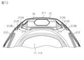
- FIG. 10 is a perspective view of the shell 11 and the rear spoiler 21 as seen from the lower rear side, with the rear flap 22 omitted for convenience of explaining the arrangement of the wing portions 212. As shown in FIG.
- a portion of the wing portion 212 is spaced from the rear end of the shell upper surface 112 .
- the wing portion 212 defines a wing gap 21H between the inner surface of the wing portion 212 and the rear side of the shell 11 .
- the wing gap 21H has a tunnel shape penetrating from the front to the rear (see FIGS. 10 and 16).
- the wing gap 21H has a thin layer shape along the outer surface of the shell 11 defined by the rear side portion of the outer surface of the shell 11 and the curved wing portion 212 following the rear side portion.
- the wing gap 21H has an opening so as to face a portion slightly above the rear end portion of the inflow guide surface 11C in the front-rear direction.
- the first wing straightening plate 212B and the second wing straightening plate 212C are positioned inside the wing gap 21H.
- the first wing straightening plate 212B and the second wing straightening plate 212C are arranged in the wing gap 21H so as to face the opening of the wing gap 21H.
- the inflow guide surface 11C causes the direction of the air flow to follow the direction in which the inflow guide surfaces 11C are connected. increase the velocity of the airflow flowing through (see Figure 4).
- the wing inflow end face 212A is inclined so that the wing gap 21H widens from the front to the rear.
- the wing inflow end face 212A increases the velocity of the airflow entering the wing gap 21H and suppresses turbulence of the airflow near the outer surface of the wing portion 212 (see FIG. 9).
- a wing gap 21H defined by the outer surface of the shell 11 and the wing portion 212 receives a high-speed airflow flowing along the inflow guide surface 11C.
- the direction of the airflow flowing through the wing gap 21H is changed rearward and downward in the wing gap 21H by the first wing straightening plate 212B and the second wing straightening plate 212C.
- the airflow flowing through the wing gap 21H is directed toward the lower rear side of the wing portion 212 by the straightening of the first wing straightening plate 212B and the second wing straightening plate 212C (see FIGS. 10 and 16).
- the rear flap 22 is a plate-like member extending vertically.
- An example of the material forming the rear flap 22 is one selected from the group consisting of acrylonitrile-butadiene-styrene copolymer, polycarbonate, and thermosetting resin impregnated with reinforcing fibers.
- the outer surface of the rear flap 22 has a curved shape that is smoothly connected in the vertical direction and extends smoothly rearward at the rear portion 113 of the shell 11 .
- the rear flap 22 has a flap front edge 22E, which is the front edge of the rear flap 22 .
- the flap front edge 22E has a gently curved shape that follows the lower side of the rear portion 113 of the shell 11. As shown in FIG. The rear flap 22 protrudes rearward from the rear portion 113 of the shell 11 so as to press the flap front edge 22E against the rear portion 113 of the shell 11 and continue from the rear portion 113 .
- the outer surface of the upper end of the rear flap 22 is provided with a flap current plate 22A.
- the flap current plate 22A is an example of a current plate included in the rear flap 22 .
- the flap current plate 22A is erected on the outer surface of the rear flap 22. As shown in FIG.
- the flap current plate 22 ⁇ /b>A has a flat plate shape rising from the outer surface of the rear flap 22 toward the inner surface of the wing portion 212 .
- the flap straightening portion 22T which is the upper end portion of the rear flap 22, includes a fitting portion 22L projecting upward and a fitting portion 22L projecting downward.
- the lower portion of the rear flap 22 includes a flap front edge 22E (see FIG. 11).
- the lower portion of the rear flap 22 is positioned on the outer surface of the shell 11 by joining with the flap connecting portion 11E described above.
- the upper end portion of the rear flap 22 is positioned on the outer surface of the shell 11 by fitting the flap support portion 182 and the fitting portion 22L.
- the inner surface of the rear flap 22 is provided with a flap connection plate 222 and gap ribs 22B.
- the flap connection portion 11E to which the rear flap 22 is joined is formed on the outer surface of the shell 11 so that the outer surface of the rear flap 22 and the shell lower surface 111 are continuously connected as a smooth curved surface. More recessed than 11D.
- the flap connecting plate 222 protrudes from the inner surface of the rear flap 22 by the depth of the flap connecting portion 11E.
- the flap connecting plate 222 of the rear flap 22 fills the depth of the flap connecting portion 11E, so that the outer surface of the rear flap 22 and the shell lower surface 111 are smoothly curved surfaces.
- the clearance rib 22B is erected on the inner surface of the rear flap 22.
- the gap ridge rib 22B is located below the flap straightening portion 22T, which is the upper end portion of the rear flap 22.
- the clearance rib 22B is a reinforcing rib rising from the inner surface of the rear flap 22 toward the flap connecting portion 11E along the direction in which the rear flap 22 extends.
- FIG. 13 is a perspective view of the shell 11 and the rear flap 22 as seen from the lower rear side, with the rear spoiler 21 omitted for convenience of explaining the arrangement of the rear flap 22.
- FIG. 13 the flap straightening portion 22T, which is the upper end portion of the rear flap 22, is separated from the outer surface of the shell 11.
- the flap straightening portion 22T of the rear flap 22 defines a flap gap 22H that is a gap between the inner surface of the rear flap 22 and the rear side portion of the shell 11 .
- the flap gap 22H has a tunnel shape penetrating from the front to the rear.
- the flap gap 22H has a thin layer shape along the outer surface of the shell 11 defined by the rear side portion of the outer surface of the shell 11 and the curved rear flap 22 following the rear side portion.
- the clearance rib 22B is arranged so as to substantially abut against the outer surface of the shell 11 .
- the flap straightening portion 22T and the clearance rib 22B divide the rear flap 22 into an upper portion and a lower portion in the vertical direction.
- the lower end of the flap gap 22H in the vertical direction is located at the upper end of the gap projection rib 22B.
- the flap straightening section 22T which is the upper end of the rear flap 22, is arranged below the wing section 212.
- the flap straightening portion 22T of the rear flap 22 is arranged behind the first wing straightening plate 212B and the second wing straightening plate 212C.
- the flap straightening plate 22A is arranged behind the first wing straightening plate 212B and the second wing straightening plate 212C.
- the flap straightening portion 22T which is the upper end portion of the rear flap 22, is located in the wing gap 21H between the rear side portion of the shell 11 and the wing portion 212. As shown in FIG. The flap straightening portion 22T of the rear flap 22 divides the longitudinal rear space in the wing gap 21H into two layers along the outer surface of the shell 11 .
- the space below the wing gap 21H divided into two layers constitutes the flap gap 22H.
- the flap current plate 22A is arranged in the space above the wing gap 21H divided into two layers.
- the flap current plate 22A extends rearward and downward in the upper space of the wing gap 21H.
- the apex in the outer surface of shell 11 allows air to flow smoothly along the apex.
- the spoiler portion 211 of the rear spoiler 21 directs the air that flows along the top of the outer surface of the shell 11 toward the rear of the shell 11 .
- the air flowing out rearward of the spoiler portion 211 is separated from the helmet further rearward than the shell 11 by the amount that flows along the spoiler portion 211 .
- the sides within the outer surface of the shell 11 allow air to flow smoothly along the sides.
- the rear flap 22 directs the air flowing along the sides of the outer surface of the shell 11 further toward the rear of the cap body.
- the air that flows behind the rear flap 22 is separated from the helmet further behind the shell 11 by the amount that flows along the rear flap 22 .
- the sides within the outer surface of the shell 11 allow air to flow smoothly along the sides.
- the wing portions 212 of the rear spoiler 21 experience air resistance from air flowing along the sides within the outer surface of the shell 11, pulling the shell 11 rearward.
- the first wing straightening plate 212B and the second wing straightening plate 212C are positioned in the wing gap 21H between the outer surface of the shell 11 and the wing portion 212 .
- the first wing straightening plate 212B and the second wing straightening plate 212C direct the flow of air entering the wing gap 21H from the front end of the wing gap 21H toward the rear and downward, so that the air flows from the rear end of the wing gap 21H. out.
- the wing portion 212 of the rear spoiler 21 changes the direction of the force received from the air flowing along the side portion of the shell 11 from the rearward direction that pulls the shell 11 rearward to the rear lower side.
- Fig. 17 shows the fluid analysis results of the running wind around the helmet.
- the fluid analysis result of running wind is the analysis result using CFD simulation, and in FIG. 17, the darker the part, the higher the flow velocity.
- the inflow guide surface 11C Like the inflow guide surface 11C described above, a surface that rises in a smooth surface reduces the flow velocity of air in front of the raised surface, while increasing the flow speed behind the raised surface. As a result, as shown in FIG. 17, the inflow guide surface 11C follows the direction of the relatively high-speed airflow in the airflow along the outer surface of the shell 11 in the direction in which the inflow guide surfaces 11C are connected. Let As a result, a relatively high-speed airflow flows into the wing gap 21H between the rear side portion of the outer surface of the shell 11 and the wing portion 212 .
- the resultant force FC received by the shell 11 as a result of running wind is a combination of the component FL that lifts the shell 11 and the component FD that pulls the shell 11 rearward.
- the air flowing along the sides of the outer surface of the shell 11 is rectified by the wings 212 of the rear spoiler 21, and the direction of the force acting on the shell 11 is changed rearward and downward.
- This change in direction of one component by the wing portion 212 causes the resultant force FC to change from the dashed line to the solid line in FIG. A component FL that pulls up the shell 11 is reduced.
- the helmet suppresses the force that pulls up the wearer's head, and thus enhances the wearer's feeling of wearing the helmet while driving.
- the rectification by the inflow guide surface 11C substantially suppresses an increase in the component FD that pulls the shell 11 rearward, and enhances the effectiveness of changing the direction of the force acting on the shell 11 rearward and downward.
- the following effects can be obtained. (1) When the air that has flowed along the top of the outer surface of the shell 11 is separated from the helmet, it flows along the spoiler portion 211 further behind the helmet so that it can be prevented from rotating. to form In addition, the air that has flowed along the sides of the outer surface of the shell 11 is further behind the helmet by the amount that it has flowed along the rear flap 22 when it is peeled off from the helmet, so that it is prevented from rotating. to form As a result, the helmet suppresses the formation of vortices behind the helmet and gives the wearer a sense of stability.
- a change in the direction of one component by the wing portion 212 substantially suppresses an increase in the component FD that pulls the shell 11 rearward, while reducing the component FL that pulls the shell 11 up in the resultant force FC.
- the helmet suppresses the force that pulls up the wearer's head, and thus enhances the wearer's feeling of wearing the helmet while driving.
- each wing portion 212 may be provided with two straightening vanes. Two rectifying plates provided in each wing portion 212 enhance the effectiveness of changing the direction of one component by the wing portion 212 .
- the upper end of the rear flap 22 divides the wing gap 21H into a flap gap 22H and another space in layers.
- the division of the wing gap 21H by the upper end of the rear flap 22 encourages the air flowing through the wing gap 21H to flow in layers along the rear sides.
- the rectification by the upper end of the rear flap 22 enhances the effectiveness of the effect according to the above (2).
- the rectification by the upper end of the rear flap 22 allows more detailed control of the direction of the force received from the air flowing along the sides than rectification by the wing portion 212 alone.
- the air that has flowed into the wing gap 21H is first rectified so as to descend from the front end of the wing gap 21H by the first wing straightening plate 212B and the second wing straightening plate 212C provided in the wing portion 212.
- the rectified air is then guided by the upper end of the rear flap 22 into a laminar flow along the rear side, and is further induced rearward and downward by the flap rectifying plate 22A of the rear flap 22. .
- Such rectification by the flap rectification plate 22A enhances the effectiveness of the effect according to the above (2).
- the wing inflow end face 212A is inclined so that the wing gap 21H widens from the front to the rear. As a result, the flow of air is accelerated in the wing gap 21 ⁇ /b>H, and turbulence of the air flow is suppressed near the outer surface of the wing portion 212 .
- the above embodiment can also be implemented with the following modifications.
- the spoiler portion 211 and the two wing portions 212 may be configured as separate resin moldings. It should be noted that, like the rear spoiler 21, a resin molded body in which the spoiler portion 211 and the two wing portions 212 are integrally formed facilitates increasing the mechanical strength of the two wing portions 212 themselves. In addition, the sense of unity between the spoiler portion 211 and the two wing portions 212 is created to enhance the design.
- wing portion 212 makes it easier to equip one wing portion 212 with a plurality of straightening vanes.
- Equipping one wing portion 212 with a plurality of straightening vanes enhances the effectiveness of directing the direction of the force that the wing portion 212 receives from the air toward the rear and downward.
- the configuration in which one wing portion 212 is provided with a plurality of rectifying plates having mutually different shapes enhances the accuracy related to the control of the direction of the combined component.
- the rear spoiler 21 and the two rear flaps 22 can constitute an airflow control section.
- the helmet may have a configuration in which the two rear flaps 22 are omitted.
- the helmet having the wing portions 212 changes the direction of the force that the wing portions 212 receive from the air backward and downward. Therefore, even if the helmet provided with the wing portion 212 does not have the rear flap 22, it is possible to obtain the effect according to the above (2).
- the configuration in which the wing gap 21H is divided into two layers by the flap straightening section 22T, which is the upper end of the rear flap 22, contributes to the straightening in the wing gap 21H and the increase in the flow velocity of the air flow, thereby contributing to the air flow control section. Improve the effectiveness of improving the feeling of wearing.
- the front end surface of the wing portion 212 may have a shape that follows the outer surface of the shell 11 . That is, the front end surface of the wing portion 212 may have a shape that makes the thickness of the wing gap 21H substantially uniform from the front to the rear. If the front end surface of the wing portion 212 is an inclined surface that widens the wing gap 21H from the front to the rear, the effect according to the above (6) can be obtained.
- the number of straightening vanes included in the wing portion 212 may be one, or may be three or more.
- the rectifying plate provided in the wing portion 212 may be only the first wing rectifying plate 212B, or may be only the second wing rectifying plate 212C.
- the first wing straightening vanes 212B, the second wing straightening vanes 212C, and the flap straightening vanes 22A only need to have a shape extending rearward and downward. may have shapes extending in different directions.
- the first wing straightening plate 212B, the second wing straightening plate 212C, and the flap straightening plate 22A may each have a shape extending inward in the left-right direction, or a shape extending outward in the left-right direction. It's okay.
- the wing part 212 may omit the straightening plate. At this time, the wing part 212 is configured to change the force that the wing part 212 receives from the air toward the rear and downward.
- the wing portion 212 may define the wing gap 21H extending from the front toward the rear and lower side by the shape of the wing portion 212 itself.
- the outer surface of the shell 11 has a recess extending from the front to the rear and downward
- the wing portion 212 has a wing gap 21H extending from the front to the rear and downward to the shape of the recess on the outer surface of the shell 11.
- the wing portion 212 may include a channel extending from the front to the rear and downward.
- the helmet may have a configuration in which the rear spoiler 21 is omitted, or a configuration in which the wing portion 212 is omitted.
- the wing portion 212 has a curved surface shape that follows the portion of the rear side portion of the shell 11 that faces the wing portion 212, and a gap penetrating from the front to the rear between the rear side portion and the wing portion 212. are arranged to define The function of the wing portion 212 may be combined with the rear flap 22 .
- the flap straightening portion 22T of the rear flap 22 may configure the flap gap 22H so as to shift the force that the rear flap 22 receives from the air downward and rearward. In such a configuration, the flap straightening portion 22T of the rear flap 22 constitutes a wing portion.
- the shell 11 may be provided with a hole 11H (see FIG. 16) for discharging air entering the shell 11 to the outside of the shell 11 in at least one of the wing gap 21H and the flap gap 22H. That is, the shell 11 may be provided with holes 11H for allowing air to flow out from the inside of the shell 11 in the portion facing the wing portion 212 and/or the rear flap 22 in the rear side portion. Such a hole 11H may be an outlet of another flow path branched from the middle of the flow path leading to the top outlet 17 or an outlet of another flow path independent of the flow path leading to the top outlet 17 .
- the wing gap 21H and the flap gap 22H are passageways for air having a high flow velocity.
- a configuration that allows air to flow through such a gap that is, a configuration in which at least one of the wing gap 21H and the flap gap 22H is provided with holes 11H functioning as air outlets increases the exhaust efficiency required for the air outlets. That is, the efficiency of expelling air from the inside of the shell 11 is enhanced.
- the helmet is not limited to a full-face helmet, and can be changed to various types of helmets, such as a flip-up helmet with a raised chin and an open-face helmet without a chin.
Landscapes
- Physics & Mathematics (AREA)
- Fluid Mechanics (AREA)
- Helmets And Other Head Coverings (AREA)
- Structures Of Non-Positive Displacement Pumps (AREA)
Abstract
Description
まず、(i)ヘルメットの全体構成を説明し、次に(ii)第1空気流制御部材の構成を説明し、(iii)第2空気流制御部材の構成を説明し、次に(iv)各空気流制御部材の相対的な関係と、ヘルメットの作用とを説明する。
また、ヘルメットにおける前後方向の中央を通る仮想的な鉛直面は、前後中心面である。前後中心面よりも前側を単に前側、前後中心面よりも後側を単に後側ともいう。
(i)ヘルメットの全体構成
図1が示すように、ヘルメットは、帽体の一例であるシェル11と、第1空気流制御部材の一例であるリアスポイラー21とを備える。ヘルメットは、2つのリアフラップ22を備えてもよい。2つのリアフラップ22の各々は、第2空気流制御部材の一例である。このように、リアスポイラー21と、2つのリアフラップ22とが、空気流制御部を構成してもよい。シェル11は、フロントロアインレット15、フロントアッパーインレット16、およびトップアウトレット17を備えてもよい。
図6が示すように、リアスポイラー21は、左右方向に広がる板状部材である。リアスポイラー21は、スポイラー部211と、2つのウイング部212とを備える。2つのウイング部212は、それぞれ、スポイラー部211の左右方向における両端部に設けられている。
図11が示すように、リアフラップ22は、上下方向に延びる板状部材である。リアフラップ22を構成する材料の一例は、アクリロニトリル・ブタジエン・スチレン共重合体、ポリカーボネート、および、強化繊維を含浸させた熱硬化性樹脂からなる群から選択される1つである。
図13が示すように、リアフラップ22の上端部であるフラップ整流部22Tは、シェル11の外表面から離間している。リアフラップ22のフラップ整流部22Tは、リアフラップ22の内面とシェル11の後方側部との間の隙間であるフラップ隙間22Hを画定する。フラップ隙間22Hは、前方から後方に向けて貫通するトンネル状を有する。フラップ隙間22Hは、シェル11の外表面における後方側部と、当該後方側部に追従する曲面状を有したリアフラップ22とに画定された、シェル11の外表面に沿う薄い層状を有する。隙間用突条リブ22Bは、シェル11の外表面とほぼ当接するように配置される。フラップ整流部22Tと隙間用突条リブ22Bとは、上下方向において、リアフラップ22を上側部分と下側部分とに分割する。フラップ隙間22Hの上下方向における下端は、隙間用突条リブ22Bの上端に位置する。
シェル11の外表面のなかの頂部は、当該頂部に沿って円滑に空気を流す。リアスポイラー21のスポイラー部211は、シェル11の外表面のなかの頂部に沿って流れる空気を、さらにシェル11の後方に向けて流す。スポイラー部211の後方に流れ出る空気は、スポイラー部211に沿って流れた分だけシェル11よりもさらに後方で、ヘルメットから剥がれる。
(1)シェル11の外表面のなかの頂部に沿って流れた空気は、ヘルメットから剥がれる際、スポイラー部211に沿って流れた分だけヘルメットのさらに後方で、回転を抑えられるように、小さい渦流を形成する。また、シェル11の外表面のなかの側部に沿って流れた空気は、ヘルメットから剥がれる際、リアフラップ22に沿って流れた分だけヘルメットのさらに後方で、回転の抑えられるように、小さい渦流を形成する。これらによって、ヘルメットは、ヘルメットの後方における渦流の形成を抑えて装着者に安定感を与える。
[空気流制御部]
・スポイラー部211と2つのウイング部212とは、互いに別体の樹脂成形体として構成されてもよい。なお、リアスポイラー21のように、スポイラー部211と2つのウイング部212とを一体とする樹脂成形体は、2つのウイング部212そのものの機械的な強度を高めることを容易にする。また、スポイラー部211と2つのウイング部212との一体感を醸し出して意匠性を高める。
・ヘルメットは、フルフェイス型ヘルメットに限らず、アゴ部が上昇可能なフリップアップ型ヘルメット、アゴ部の無いオープンフェイス型ヘルメットなどの各種のヘルメットに変更可能である。
Claims (8)
- 帽体と、
前記帽体の外表面に取り付けられる空気流制御部と、
を備えるヘルメットであって、
前記空気流制御部は、
前記帽体の外表面のなかの後側部分を左右方向に挟む2つのウイング部を備え、
前記2つのウイング部の各々は、
前記帽体の外表面のなかの後方側部の一部から連なるように前記後方側部に接続され、かつ、前記後方側部のなかで前記ウイング部と対向する部分に追従する曲面状を有すると共に、前記後方側部と前記ウイング部との間に前方から後方に向けて貫通する隙間を画定し、前記隙間に前方から入る空気を後方下側に向けて出すように構成される
ヘルメット。 - 前記空気流制御部は
前記隙間のなかで後方下側に向けて延びる整流板をさらに備える
請求項1に記載のヘルメット。 - 前記帽体は、
前記後方側部のなかで前記2つのウイング部のうちの1つと対向する部分に前記帽体の内部からの空気の流出を許容する孔を備える
請求項1または2に記載のヘルメット。 - 前記空気流制御部は、前記帽体の外表面のなかの前記後側部分から連なるように前記後側部分から前記帽体の後方に向けて突き出るスポイラー部をさらに備え、
前記スポイラー部は、前記2つのウイング部によって左右方向に挟まれており、
前記2つのウイング部の各々は、
前記帽体の外表面のなかの前記後方側部の前記一部から連なるように前記後方側部と前記スポイラー部とに接続され、かつ、前記後方側部と前記スポイラー部との間に前記隙間を画定し、
前記空気流制御部は、前記スポイラー部と前記2つのウイング部とが一体に成形された樹脂成形体であり、
前記2つのウイング部の各々は、前記隙間のなかで後方下側に向けて延びる複数の整流板を備える
請求項1から3のいずれか一項に記載のヘルメット。 - 前記帽体の外表面のなかの前記後方側部の前記一部は、ウイング接続部であり、
前記帽体の外表面のなかの前記後方側部は、前記ウイング接続部の後方下側にフラップ接続部を備え、
前記空気流制御部は、
前記2つのウイング部を備える第1空気流制御部材と、
前記第1空気流制御部材の下方後側に位置するフラップである第2空気流制御部材と、を備え、
前記第2空気流制御部材は、
前記フラップ接続部から連なるように前記後方側部から前記帽体の後方に向けて突き出る板状を有し、
前記第2空気流制御部材の上端部は、
前記後方側部と前記2つのウイング部の1つとの間の前記隙間を前記帽体の外表面に沿う2層に分割するように、前記隙間に位置する
請求項1から4のいずれか一項に記載のヘルメット。 - 前記第2空気流制御部材の前記上端部は、前記第2空気流制御部材の前記上端部と前記第1空気流制御部材との隙間のなかで後方下側に向けて延びる整流板を備える
請求項5に記載のヘルメット。 - 前記2つのウイング部のうちの1つは前側端面を有し、前記前側端面は、前記後方側部と前記ウイング部との間の前記隙間が前方から後方に向けて広がるように、傾斜している
請求項1から6のいずれか一項に記載のヘルメット。 - 前記帽体の外表面のなかの側部は、流入誘導面を備え、
前記流入誘導面は、前記帽体の外表面のなかの前記側部において盛り上がる曲面であり、前記後方側部と前記2つのウイング部のうちの1つとの間の前記隙間に向けて前記隙間の前方から走行風を流入させるように、前記帽体の前側部分から前記隙間の前方に向けて連なる
請求項1から7のいずれか一項に記載のヘルメット。
Priority Applications (3)
| Application Number | Priority Date | Filing Date | Title |
|---|---|---|---|
| US18/710,033 US20250000197A1 (en) | 2021-11-17 | 2022-10-13 | Helmet |
| CN202280072795.XA CN118175942A (zh) | 2021-11-17 | 2022-10-13 | 头盔 |
| EP22895289.1A EP4434385A4 (en) | 2021-11-17 | 2022-10-13 | HELMET |
Applications Claiming Priority (2)
| Application Number | Priority Date | Filing Date | Title |
|---|---|---|---|
| JP2021-187263 | 2021-11-17 | ||
| JP2021187263A JP7762547B2 (ja) | 2021-11-17 | 2021-11-17 | ヘルメット |
Publications (1)
| Publication Number | Publication Date |
|---|---|
| WO2023090003A1 true WO2023090003A1 (ja) | 2023-05-25 |
Family
ID=86396589
Family Applications (1)
| Application Number | Title | Priority Date | Filing Date |
|---|---|---|---|
| PCT/JP2022/038226 Ceased WO2023090003A1 (ja) | 2021-11-17 | 2022-10-13 | ヘルメット |
Country Status (5)
| Country | Link |
|---|---|
| US (1) | US20250000197A1 (ja) |
| EP (1) | EP4434385A4 (ja) |
| JP (1) | JP7762547B2 (ja) |
| CN (1) | CN118175942A (ja) |
| WO (1) | WO2023090003A1 (ja) |
Families Citing this family (5)
| Publication number | Priority date | Publication date | Assignee | Title |
|---|---|---|---|---|
| USD1066814S1 (en) * | 2021-11-08 | 2025-03-11 | Liding Tang | Motorcycle helmet |
| USD1066815S1 (en) * | 2021-12-03 | 2025-03-11 | Liding Tang | Motorcycle helmet |
| USD1122566S1 (en) * | 2023-03-31 | 2026-04-21 | Alpinestars Research S.p.A. | Helmet part |
| USD1073193S1 (en) * | 2024-04-18 | 2025-04-29 | Shark | Motorcycle helmet |
| USD1111320S1 (en) * | 2024-07-24 | 2026-02-10 | Henry Tedjakusuma | Helmet |
Citations (5)
| Publication number | Priority date | Publication date | Assignee | Title |
|---|---|---|---|---|
| JPH0226908A (ja) | 1987-12-15 | 1990-01-29 | Nolan Spa | 防護ヘルメット |
| JPH073516A (ja) | 1993-06-11 | 1995-01-06 | Shoei Kako Kk | 乗車用ヘルメットの換気装置 |
| JP2000328343A (ja) | 1999-05-25 | 2000-11-28 | Ogk Hanbai Kk | 換気機能を有するヘルメット及び換気用シャッター装置 |
| WO2007144937A1 (ja) | 2006-06-13 | 2007-12-21 | Ogk Kabuto Co., Ltd. | ヘルメット用ウエイクスタビライザ及びヘルメット |
| JP2020133065A (ja) * | 2019-02-22 | 2020-08-31 | 株式会社Shoei | ヘルメット用気流制御部材、および、ヘルメット |
Family Cites Families (2)
| Publication number | Priority date | Publication date | Assignee | Title |
|---|---|---|---|---|
| JP4222933B2 (ja) * | 2001-06-12 | 2009-02-12 | 株式会社Shoei | ヘルメット |
| JP4533922B2 (ja) * | 2007-10-04 | 2010-09-01 | 株式会社アライヘルメット | ヘルメット |
-
2021
- 2021-11-17 JP JP2021187263A patent/JP7762547B2/ja active Active
-
2022
- 2022-10-13 CN CN202280072795.XA patent/CN118175942A/zh active Pending
- 2022-10-13 WO PCT/JP2022/038226 patent/WO2023090003A1/ja not_active Ceased
- 2022-10-13 EP EP22895289.1A patent/EP4434385A4/en active Pending
- 2022-10-13 US US18/710,033 patent/US20250000197A1/en active Pending
Patent Citations (5)
| Publication number | Priority date | Publication date | Assignee | Title |
|---|---|---|---|---|
| JPH0226908A (ja) | 1987-12-15 | 1990-01-29 | Nolan Spa | 防護ヘルメット |
| JPH073516A (ja) | 1993-06-11 | 1995-01-06 | Shoei Kako Kk | 乗車用ヘルメットの換気装置 |
| JP2000328343A (ja) | 1999-05-25 | 2000-11-28 | Ogk Hanbai Kk | 換気機能を有するヘルメット及び換気用シャッター装置 |
| WO2007144937A1 (ja) | 2006-06-13 | 2007-12-21 | Ogk Kabuto Co., Ltd. | ヘルメット用ウエイクスタビライザ及びヘルメット |
| JP2020133065A (ja) * | 2019-02-22 | 2020-08-31 | 株式会社Shoei | ヘルメット用気流制御部材、および、ヘルメット |
Non-Patent Citations (1)
| Title |
|---|
| See also references of EP4434385A4 |
Also Published As
| Publication number | Publication date |
|---|---|
| US20250000197A1 (en) | 2025-01-02 |
| EP4434385A4 (en) | 2025-10-29 |
| EP4434385A1 (en) | 2024-09-25 |
| CN118175942A (zh) | 2024-06-11 |
| JP7762547B2 (ja) | 2025-10-30 |
| JP2023074347A (ja) | 2023-05-29 |
Similar Documents
| Publication | Publication Date | Title |
|---|---|---|
| WO2023090003A1 (ja) | ヘルメット | |
| JP3046820B1 (ja) | 換気機能を有するヘルメット及び換気用シャッター装置 | |
| EP0320622B1 (en) | Safety helmet for motor-cyclists provided with manually-adjustable ventilation means | |
| JP5983568B2 (ja) | 車両下部構造 | |
| EP2574529B1 (en) | Tank shroud structure | |
| US11000089B2 (en) | Helmet | |
| EP2156760B1 (en) | Shield for helmet, and helmet including such shield | |
| JP2016020132A (ja) | 車両用スポイラ装置 | |
| EP3698665B1 (en) | Helmet airflow control member and helmet | |
| JP2022162800A (ja) | 車両の前部構造 | |
| CN101448419B (zh) | 头盔用尾流稳定器及头盔 | |
| CN110542136B (zh) | 吸油烟机 | |
| US20130340151A1 (en) | Bicycle helmet with vent | |
| JP2012126326A (ja) | 車両の側部車体構造 | |
| JP6549820B2 (ja) | シールド及びヘルメット | |
| US12275477B2 (en) | Straddled vehicle | |
| US11639206B2 (en) | Airflow deflector | |
| JP2002308154A (ja) | 車両のフロント下部構造 | |
| JP5879056B2 (ja) | 車体構造 | |
| WO2013065176A1 (ja) | ヘルメット | |
| JP7155941B2 (ja) | 車両の前部構造 | |
| JP2001089926A (ja) | ヘルメットの通風構造 | |
| CN222611090U (zh) | 用于车辆的下护板组件及车辆 | |
| KR20260053709A (ko) | 헬멧 | |
| TH2401002939A (th) | หมวกนิรภัย |
Legal Events
| Date | Code | Title | Description |
|---|---|---|---|
| 121 | Ep: the epo has been informed by wipo that ep was designated in this application |
Ref document number: 22895289 Country of ref document: EP Kind code of ref document: A1 |
|
| WWE | Wipo information: entry into national phase |
Ref document number: 202280072795.X Country of ref document: CN |
|
| WWE | Wipo information: entry into national phase |
Ref document number: 2401002939 Country of ref document: TH |
|
| WWE | Wipo information: entry into national phase |
Ref document number: 18710033 Country of ref document: US |
|
| WWE | Wipo information: entry into national phase |
Ref document number: 2022895289 Country of ref document: EP |
|
| ENP | Entry into the national phase |
Ref document number: 2022895289 Country of ref document: EP Effective date: 20240617 |