WO2023090138A1 - 無方向性電磁鋼板とその製造方法並びにモータコアの製造方法 - Google Patents
無方向性電磁鋼板とその製造方法並びにモータコアの製造方法 Download PDFInfo
- Publication number
- WO2023090138A1 WO2023090138A1 PCT/JP2022/040677 JP2022040677W WO2023090138A1 WO 2023090138 A1 WO2023090138 A1 WO 2023090138A1 JP 2022040677 W JP2022040677 W JP 2022040677W WO 2023090138 A1 WO2023090138 A1 WO 2023090138A1
- Authority
- WO
- WIPO (PCT)
- Prior art keywords
- steel sheet
- less
- oriented electrical
- electrical steel
- rolling
- Prior art date
- Legal status (The legal status is an assumption and is not a legal conclusion. Google has not performed a legal analysis and makes no representation as to the accuracy of the status listed.)
- Ceased
Links
Classifications
-
- H—ELECTRICITY
- H01—ELECTRIC ELEMENTS
- H01F—MAGNETS; INDUCTANCES; TRANSFORMERS; SELECTION OF MATERIALS FOR THEIR MAGNETIC PROPERTIES
- H01F1/00—Magnets or magnetic bodies characterised by the magnetic materials therefor; Selection of materials for their magnetic properties
- H01F1/01—Magnets or magnetic bodies characterised by the magnetic materials therefor; Selection of materials for their magnetic properties of inorganic materials
- H01F1/03—Magnets or magnetic bodies characterised by the magnetic materials therefor; Selection of materials for their magnetic properties of inorganic materials characterised by their coercivity
- H01F1/12—Magnets or magnetic bodies characterised by the magnetic materials therefor; Selection of materials for their magnetic properties of inorganic materials characterised by their coercivity of soft-magnetic materials
- H01F1/14—Magnets or magnetic bodies characterised by the magnetic materials therefor; Selection of materials for their magnetic properties of inorganic materials characterised by their coercivity of soft-magnetic materials metals or alloys
- H01F1/147—Alloys characterised by their composition
- H01F1/14766—Fe-Si based alloys
- H01F1/14775—Fe-Si based alloys in the form of sheets
- H01F1/14783—Fe-Si based alloys in the form of sheets with insulating coating
-
- C—CHEMISTRY; METALLURGY
- C21—METALLURGY OF IRON
- C21D—MODIFYING THE PHYSICAL STRUCTURE OF FERROUS METALS; GENERAL DEVICES FOR HEAT TREATMENT OF FERROUS OR NON-FERROUS METALS OR ALLOYS; MAKING METAL MALLEABLE, e.g. BY DECARBURISATION OR TEMPERING
- C21D6/00—Heat treatment of ferrous alloys
- C21D6/001—Heat treatment of ferrous alloys containing Ni
-
- C—CHEMISTRY; METALLURGY
- C21—METALLURGY OF IRON
- C21D—MODIFYING THE PHYSICAL STRUCTURE OF FERROUS METALS; GENERAL DEVICES FOR HEAT TREATMENT OF FERROUS OR NON-FERROUS METALS OR ALLOYS; MAKING METAL MALLEABLE, e.g. BY DECARBURISATION OR TEMPERING
- C21D6/00—Heat treatment of ferrous alloys
- C21D6/002—Heat treatment of ferrous alloys containing Cr
-
- C—CHEMISTRY; METALLURGY
- C21—METALLURGY OF IRON
- C21D—MODIFYING THE PHYSICAL STRUCTURE OF FERROUS METALS; GENERAL DEVICES FOR HEAT TREATMENT OF FERROUS OR NON-FERROUS METALS OR ALLOYS; MAKING METAL MALLEABLE, e.g. BY DECARBURISATION OR TEMPERING
- C21D6/00—Heat treatment of ferrous alloys
- C21D6/005—Heat treatment of ferrous alloys containing Mn
-
- C—CHEMISTRY; METALLURGY
- C21—METALLURGY OF IRON
- C21D—MODIFYING THE PHYSICAL STRUCTURE OF FERROUS METALS; GENERAL DEVICES FOR HEAT TREATMENT OF FERROUS OR NON-FERROUS METALS OR ALLOYS; MAKING METAL MALLEABLE, e.g. BY DECARBURISATION OR TEMPERING
- C21D6/00—Heat treatment of ferrous alloys
- C21D6/007—Heat treatment of ferrous alloys containing Co
-
- C—CHEMISTRY; METALLURGY
- C21—METALLURGY OF IRON
- C21D—MODIFYING THE PHYSICAL STRUCTURE OF FERROUS METALS; GENERAL DEVICES FOR HEAT TREATMENT OF FERROUS OR NON-FERROUS METALS OR ALLOYS; MAKING METAL MALLEABLE, e.g. BY DECARBURISATION OR TEMPERING
- C21D6/00—Heat treatment of ferrous alloys
- C21D6/008—Heat treatment of ferrous alloys containing Si
-
- C—CHEMISTRY; METALLURGY
- C21—METALLURGY OF IRON
- C21D—MODIFYING THE PHYSICAL STRUCTURE OF FERROUS METALS; GENERAL DEVICES FOR HEAT TREATMENT OF FERROUS OR NON-FERROUS METALS OR ALLOYS; MAKING METAL MALLEABLE, e.g. BY DECARBURISATION OR TEMPERING
- C21D8/00—Modifying the physical properties of ferrous metals or ferrous alloys by deformation combined with, or followed by, heat treatment
- C21D8/12—Modifying the physical properties of ferrous metals or ferrous alloys by deformation combined with, or followed by, heat treatment during manufacturing of articles with special electromagnetic properties
- C21D8/1216—Modifying the physical properties of ferrous metals or ferrous alloys by deformation combined with, or followed by, heat treatment during manufacturing of articles with special electromagnetic properties characterised by the working steps
- C21D8/1222—Hot rolling
-
- C—CHEMISTRY; METALLURGY
- C21—METALLURGY OF IRON
- C21D—MODIFYING THE PHYSICAL STRUCTURE OF FERROUS METALS; GENERAL DEVICES FOR HEAT TREATMENT OF FERROUS OR NON-FERROUS METALS OR ALLOYS; MAKING METAL MALLEABLE, e.g. BY DECARBURISATION OR TEMPERING
- C21D8/00—Modifying the physical properties of ferrous metals or ferrous alloys by deformation combined with, or followed by, heat treatment
- C21D8/12—Modifying the physical properties of ferrous metals or ferrous alloys by deformation combined with, or followed by, heat treatment during manufacturing of articles with special electromagnetic properties
- C21D8/1216—Modifying the physical properties of ferrous metals or ferrous alloys by deformation combined with, or followed by, heat treatment during manufacturing of articles with special electromagnetic properties characterised by the working steps
- C21D8/1233—Cold rolling
-
- C—CHEMISTRY; METALLURGY
- C21—METALLURGY OF IRON
- C21D—MODIFYING THE PHYSICAL STRUCTURE OF FERROUS METALS; GENERAL DEVICES FOR HEAT TREATMENT OF FERROUS OR NON-FERROUS METALS OR ALLOYS; MAKING METAL MALLEABLE, e.g. BY DECARBURISATION OR TEMPERING
- C21D8/00—Modifying the physical properties of ferrous metals or ferrous alloys by deformation combined with, or followed by, heat treatment
- C21D8/12—Modifying the physical properties of ferrous metals or ferrous alloys by deformation combined with, or followed by, heat treatment during manufacturing of articles with special electromagnetic properties
- C21D8/1244—Modifying the physical properties of ferrous metals or ferrous alloys by deformation combined with, or followed by, heat treatment during manufacturing of articles with special electromagnetic properties characterised by the heat treatment
- C21D8/1255—Modifying the physical properties of ferrous metals or ferrous alloys by deformation combined with, or followed by, heat treatment during manufacturing of articles with special electromagnetic properties characterised by the heat treatment with diffusion of elements, e.g. decarburising, nitriding
-
- C—CHEMISTRY; METALLURGY
- C21—METALLURGY OF IRON
- C21D—MODIFYING THE PHYSICAL STRUCTURE OF FERROUS METALS; GENERAL DEVICES FOR HEAT TREATMENT OF FERROUS OR NON-FERROUS METALS OR ALLOYS; MAKING METAL MALLEABLE, e.g. BY DECARBURISATION OR TEMPERING
- C21D8/00—Modifying the physical properties of ferrous metals or ferrous alloys by deformation combined with, or followed by, heat treatment
- C21D8/12—Modifying the physical properties of ferrous metals or ferrous alloys by deformation combined with, or followed by, heat treatment during manufacturing of articles with special electromagnetic properties
- C21D8/1244—Modifying the physical properties of ferrous metals or ferrous alloys by deformation combined with, or followed by, heat treatment during manufacturing of articles with special electromagnetic properties characterised by the heat treatment
- C21D8/1261—Modifying the physical properties of ferrous metals or ferrous alloys by deformation combined with, or followed by, heat treatment during manufacturing of articles with special electromagnetic properties characterised by the heat treatment following hot rolling
-
- C—CHEMISTRY; METALLURGY
- C21—METALLURGY OF IRON
- C21D—MODIFYING THE PHYSICAL STRUCTURE OF FERROUS METALS; GENERAL DEVICES FOR HEAT TREATMENT OF FERROUS OR NON-FERROUS METALS OR ALLOYS; MAKING METAL MALLEABLE, e.g. BY DECARBURISATION OR TEMPERING
- C21D8/00—Modifying the physical properties of ferrous metals or ferrous alloys by deformation combined with, or followed by, heat treatment
- C21D8/12—Modifying the physical properties of ferrous metals or ferrous alloys by deformation combined with, or followed by, heat treatment during manufacturing of articles with special electromagnetic properties
- C21D8/1244—Modifying the physical properties of ferrous metals or ferrous alloys by deformation combined with, or followed by, heat treatment during manufacturing of articles with special electromagnetic properties characterised by the heat treatment
- C21D8/1266—Modifying the physical properties of ferrous metals or ferrous alloys by deformation combined with, or followed by, heat treatment during manufacturing of articles with special electromagnetic properties characterised by the heat treatment between cold rolling steps
-
- C—CHEMISTRY; METALLURGY
- C21—METALLURGY OF IRON
- C21D—MODIFYING THE PHYSICAL STRUCTURE OF FERROUS METALS; GENERAL DEVICES FOR HEAT TREATMENT OF FERROUS OR NON-FERROUS METALS OR ALLOYS; MAKING METAL MALLEABLE, e.g. BY DECARBURISATION OR TEMPERING
- C21D8/00—Modifying the physical properties of ferrous metals or ferrous alloys by deformation combined with, or followed by, heat treatment
- C21D8/12—Modifying the physical properties of ferrous metals or ferrous alloys by deformation combined with, or followed by, heat treatment during manufacturing of articles with special electromagnetic properties
- C21D8/1244—Modifying the physical properties of ferrous metals or ferrous alloys by deformation combined with, or followed by, heat treatment during manufacturing of articles with special electromagnetic properties characterised by the heat treatment
- C21D8/1272—Final recrystallisation annealing
-
- C—CHEMISTRY; METALLURGY
- C21—METALLURGY OF IRON
- C21D—MODIFYING THE PHYSICAL STRUCTURE OF FERROUS METALS; GENERAL DEVICES FOR HEAT TREATMENT OF FERROUS OR NON-FERROUS METALS OR ALLOYS; MAKING METAL MALLEABLE, e.g. BY DECARBURISATION OR TEMPERING
- C21D9/00—Heat treatment, e.g. annealing, hardening, quenching or tempering, adapted for particular articles; Furnaces therefor
- C21D9/46—Heat treatment, e.g. annealing, hardening, quenching or tempering, adapted for particular articles; Furnaces therefor for sheet metals
-
- C—CHEMISTRY; METALLURGY
- C22—METALLURGY; FERROUS OR NON-FERROUS ALLOYS; TREATMENT OF ALLOYS OR NON-FERROUS METALS
- C22C—ALLOYS
- C22C38/00—Ferrous alloys, e.g. steel alloys
- C22C38/001—Ferrous alloys, e.g. steel alloys containing N
-
- C—CHEMISTRY; METALLURGY
- C22—METALLURGY; FERROUS OR NON-FERROUS ALLOYS; TREATMENT OF ALLOYS OR NON-FERROUS METALS
- C22C—ALLOYS
- C22C38/00—Ferrous alloys, e.g. steel alloys
- C22C38/002—Ferrous alloys, e.g. steel alloys containing In, Mg, or other elements not provided for in one single group C22C38/001 - C22C38/60
-
- C—CHEMISTRY; METALLURGY
- C22—METALLURGY; FERROUS OR NON-FERROUS ALLOYS; TREATMENT OF ALLOYS OR NON-FERROUS METALS
- C22C—ALLOYS
- C22C38/00—Ferrous alloys, e.g. steel alloys
- C22C38/004—Very low carbon steels, i.e. having a carbon content of less than 0,01%
-
- C—CHEMISTRY; METALLURGY
- C22—METALLURGY; FERROUS OR NON-FERROUS ALLOYS; TREATMENT OF ALLOYS OR NON-FERROUS METALS
- C22C—ALLOYS
- C22C38/00—Ferrous alloys, e.g. steel alloys
- C22C38/005—Ferrous alloys, e.g. steel alloys containing rare earths, i.e. Sc, Y, Lanthanides
-
- C—CHEMISTRY; METALLURGY
- C22—METALLURGY; FERROUS OR NON-FERROUS ALLOYS; TREATMENT OF ALLOYS OR NON-FERROUS METALS
- C22C—ALLOYS
- C22C38/00—Ferrous alloys, e.g. steel alloys
- C22C38/008—Ferrous alloys, e.g. steel alloys containing tin
-
- C—CHEMISTRY; METALLURGY
- C22—METALLURGY; FERROUS OR NON-FERROUS ALLOYS; TREATMENT OF ALLOYS OR NON-FERROUS METALS
- C22C—ALLOYS
- C22C38/00—Ferrous alloys, e.g. steel alloys
- C22C38/02—Ferrous alloys, e.g. steel alloys containing silicon
-
- C—CHEMISTRY; METALLURGY
- C22—METALLURGY; FERROUS OR NON-FERROUS ALLOYS; TREATMENT OF ALLOYS OR NON-FERROUS METALS
- C22C—ALLOYS
- C22C38/00—Ferrous alloys, e.g. steel alloys
- C22C38/04—Ferrous alloys, e.g. steel alloys containing manganese
-
- C—CHEMISTRY; METALLURGY
- C22—METALLURGY; FERROUS OR NON-FERROUS ALLOYS; TREATMENT OF ALLOYS OR NON-FERROUS METALS
- C22C—ALLOYS
- C22C38/00—Ferrous alloys, e.g. steel alloys
- C22C38/06—Ferrous alloys, e.g. steel alloys containing aluminium
-
- C—CHEMISTRY; METALLURGY
- C22—METALLURGY; FERROUS OR NON-FERROUS ALLOYS; TREATMENT OF ALLOYS OR NON-FERROUS METALS
- C22C—ALLOYS
- C22C38/00—Ferrous alloys, e.g. steel alloys
- C22C38/08—Ferrous alloys, e.g. steel alloys containing nickel
-
- C—CHEMISTRY; METALLURGY
- C22—METALLURGY; FERROUS OR NON-FERROUS ALLOYS; TREATMENT OF ALLOYS OR NON-FERROUS METALS
- C22C—ALLOYS
- C22C38/00—Ferrous alloys, e.g. steel alloys
- C22C38/10—Ferrous alloys, e.g. steel alloys containing cobalt
-
- C—CHEMISTRY; METALLURGY
- C22—METALLURGY; FERROUS OR NON-FERROUS ALLOYS; TREATMENT OF ALLOYS OR NON-FERROUS METALS
- C22C—ALLOYS
- C22C38/00—Ferrous alloys, e.g. steel alloys
- C22C38/12—Ferrous alloys, e.g. steel alloys containing tungsten, tantalum, molybdenum, vanadium, or niobium
-
- C—CHEMISTRY; METALLURGY
- C22—METALLURGY; FERROUS OR NON-FERROUS ALLOYS; TREATMENT OF ALLOYS OR NON-FERROUS METALS
- C22C—ALLOYS
- C22C38/00—Ferrous alloys, e.g. steel alloys
- C22C38/14—Ferrous alloys, e.g. steel alloys containing titanium or zirconium
-
- C—CHEMISTRY; METALLURGY
- C22—METALLURGY; FERROUS OR NON-FERROUS ALLOYS; TREATMENT OF ALLOYS OR NON-FERROUS METALS
- C22C—ALLOYS
- C22C38/00—Ferrous alloys, e.g. steel alloys
- C22C38/16—Ferrous alloys, e.g. steel alloys containing copper
-
- C—CHEMISTRY; METALLURGY
- C22—METALLURGY; FERROUS OR NON-FERROUS ALLOYS; TREATMENT OF ALLOYS OR NON-FERROUS METALS
- C22C—ALLOYS
- C22C38/00—Ferrous alloys, e.g. steel alloys
- C22C38/18—Ferrous alloys, e.g. steel alloys containing chromium
- C22C38/20—Ferrous alloys, e.g. steel alloys containing chromium with copper
-
- C—CHEMISTRY; METALLURGY
- C22—METALLURGY; FERROUS OR NON-FERROUS ALLOYS; TREATMENT OF ALLOYS OR NON-FERROUS METALS
- C22C—ALLOYS
- C22C38/00—Ferrous alloys, e.g. steel alloys
- C22C38/18—Ferrous alloys, e.g. steel alloys containing chromium
- C22C38/32—Ferrous alloys, e.g. steel alloys containing chromium with boron
-
- C—CHEMISTRY; METALLURGY
- C22—METALLURGY; FERROUS OR NON-FERROUS ALLOYS; TREATMENT OF ALLOYS OR NON-FERROUS METALS
- C22C—ALLOYS
- C22C38/00—Ferrous alloys, e.g. steel alloys
- C22C38/18—Ferrous alloys, e.g. steel alloys containing chromium
- C22C38/34—Ferrous alloys, e.g. steel alloys containing chromium with more than 1.5% by weight of silicon
-
- C—CHEMISTRY; METALLURGY
- C22—METALLURGY; FERROUS OR NON-FERROUS ALLOYS; TREATMENT OF ALLOYS OR NON-FERROUS METALS
- C22C—ALLOYS
- C22C38/00—Ferrous alloys, e.g. steel alloys
- C22C38/60—Ferrous alloys, e.g. steel alloys containing lead, selenium, tellurium, or antimony, or more than 0.04% by weight of sulfur
-
- H—ELECTRICITY
- H01—ELECTRIC ELEMENTS
- H01F—MAGNETS; INDUCTANCES; TRANSFORMERS; SELECTION OF MATERIALS FOR THEIR MAGNETIC PROPERTIES
- H01F1/00—Magnets or magnetic bodies characterised by the magnetic materials therefor; Selection of materials for their magnetic properties
- H01F1/01—Magnets or magnetic bodies characterised by the magnetic materials therefor; Selection of materials for their magnetic properties of inorganic materials
- H01F1/03—Magnets or magnetic bodies characterised by the magnetic materials therefor; Selection of materials for their magnetic properties of inorganic materials characterised by their coercivity
- H01F1/12—Magnets or magnetic bodies characterised by the magnetic materials therefor; Selection of materials for their magnetic properties of inorganic materials characterised by their coercivity of soft-magnetic materials
- H01F1/14—Magnets or magnetic bodies characterised by the magnetic materials therefor; Selection of materials for their magnetic properties of inorganic materials characterised by their coercivity of soft-magnetic materials metals or alloys
- H01F1/147—Alloys characterised by their composition
- H01F1/14766—Fe-Si based alloys
-
- H—ELECTRICITY
- H01—ELECTRIC ELEMENTS
- H01F—MAGNETS; INDUCTANCES; TRANSFORMERS; SELECTION OF MATERIALS FOR THEIR MAGNETIC PROPERTIES
- H01F1/00—Magnets or magnetic bodies characterised by the magnetic materials therefor; Selection of materials for their magnetic properties
- H01F1/01—Magnets or magnetic bodies characterised by the magnetic materials therefor; Selection of materials for their magnetic properties of inorganic materials
- H01F1/03—Magnets or magnetic bodies characterised by the magnetic materials therefor; Selection of materials for their magnetic properties of inorganic materials characterised by their coercivity
- H01F1/12—Magnets or magnetic bodies characterised by the magnetic materials therefor; Selection of materials for their magnetic properties of inorganic materials characterised by their coercivity of soft-magnetic materials
- H01F1/14—Magnets or magnetic bodies characterised by the magnetic materials therefor; Selection of materials for their magnetic properties of inorganic materials characterised by their coercivity of soft-magnetic materials metals or alloys
- H01F1/147—Alloys characterised by their composition
- H01F1/14766—Fe-Si based alloys
- H01F1/14775—Fe-Si based alloys in the form of sheets
-
- H—ELECTRICITY
- H01—ELECTRIC ELEMENTS
- H01F—MAGNETS; INDUCTANCES; TRANSFORMERS; SELECTION OF MATERIALS FOR THEIR MAGNETIC PROPERTIES
- H01F41/00—Apparatus or processes specially adapted for manufacturing or assembling magnets, inductances or transformers; Apparatus or processes specially adapted for manufacturing materials characterised by their magnetic properties
- H01F41/02—Apparatus or processes specially adapted for manufacturing or assembling magnets, inductances or transformers; Apparatus or processes specially adapted for manufacturing materials characterised by their magnetic properties for manufacturing cores, coils, or magnets
- H01F41/0206—Manufacturing of magnetic cores by mechanical means
- H01F41/0233—Manufacturing of magnetic circuits made from sheets
- H01F41/024—Manufacturing of magnetic circuits made from deformed sheets
-
- C—CHEMISTRY; METALLURGY
- C22—METALLURGY; FERROUS OR NON-FERROUS ALLOYS; TREATMENT OF ALLOYS OR NON-FERROUS METALS
- C22C—ALLOYS
- C22C2202/00—Physical properties
- C22C2202/02—Magnetic
-
- Y—GENERAL TAGGING OF NEW TECHNOLOGICAL DEVELOPMENTS; GENERAL TAGGING OF CROSS-SECTIONAL TECHNOLOGIES SPANNING OVER SEVERAL SECTIONS OF THE IPC; TECHNICAL SUBJECTS COVERED BY FORMER USPC CROSS-REFERENCE ART COLLECTIONS [XRACs] AND DIGESTS
- Y02—TECHNOLOGIES OR APPLICATIONS FOR MITIGATION OR ADAPTATION AGAINST CLIMATE CHANGE
- Y02P—CLIMATE CHANGE MITIGATION TECHNOLOGIES IN THE PRODUCTION OR PROCESSING OF GOODS
- Y02P10/00—Technologies related to metal processing
- Y02P10/20—Recycling
Definitions
- the present invention relates to a non-oriented electrical steel sheet with excellent magnetic properties used as an iron core material for motors, a method for manufacturing the same, and a method for manufacturing a motor core.
- Non-oriented electrical steel sheets which are mainly used as core materials for electric vehicle drive motors and home appliance motors.
- Magnetic flux density is required. Since these magnetic properties vary greatly depending on the thickness and resistivity of the steel sheet, high-performance materials, such as high-Si electrical steel sheets, are required to be made thinner and higher alloyed by increasing the content of elements that increase resistivity, such as Si and Al. progressing. However, excessive thinning and addition of alloying elements increase the rolling load and embrittle the steel, which significantly impairs the manufacturability and increases the manufacturing cost.
- a hot-rolled steel sheet with a thickness of 2 mm to 3 mm is cold-rolled to about 0.2 mm and then recrystallized and annealed.
- ⁇ 111 ⁇ planes which are not preferable, are preferentially formed. Since the ⁇ 111 ⁇ planes are formed near the grain boundaries of the crystal grains before cold rolling, there is also a technique to anneal the hot-rolled steel sheet to reduce the frequency of grain boundaries before cold rolling and improve the magnetic properties. established, but still the ⁇ 111 ⁇ faces are predominantly formed.
- Patent Document 1 in a low-pressure atmosphere, crystal grains having low surface energy ⁇ 100 ⁇ plane orientation and ⁇ 110 ⁇ plane orientation eat and grow crystal grains having other high surface energy orientations.
- a technique using the mechanism is disclosed. Since this method does not rely on high alloying of Si, Al, etc., it has the advantage of being able to produce non-oriented electrical steel sheets having good magnetic properties without being affected by trends in alloy raw material costs.
- Patent Document 2 discloses a technique of reducing the crystal grain size to several mm and preferentially forming a ⁇ 100 ⁇ texture by combining high-purification steel and annealing in a reduced-pressure atmosphere.
- Recrystallization includes primary recrystallization, secondary recrystallization, and tertiary recrystallization, and strain energy, grain boundary energy, and surface energy are considered to be driving forces for manifestation of recrystallization, respectively.
- Patent Document 3 a technique for forming ⁇ 100 ⁇ by secondary recrystallization is disclosed in Patent Document 3.
- tertiary recrystallization it has not been sufficiently verified whether it has been realized, but it is shown in Patent Document 2, Non-Patent Document 1, and the like.
- the inventors have repeatedly studied a method for manufacturing a non-oriented electrical steel sheet in which the ⁇ 100 ⁇ plane orientation is preferentially formed in the sheet surface, including a follow-up test of the conventional technique.
- magnetic properties in the commercial frequency range such as magnetic flux density B 50 and iron loss W 15/100 are excellent by annealing in a reduced pressure atmosphere, but iron loss W 10
- the iron loss in the high frequency range such as /400 was not reduced more than expected.
- the obtained steel sheet structure was observed, and the variation in grain size was extremely large.
- the average crystal grain size was coarsened to 20 mm or more. Since the iron loss in the high frequency region is strongly affected by the magnetic domain structure, the increase in the iron loss is considered to be due to the increase in the size of the magnetic domain due to the coarsening of the crystal grains.
- Patent Document 3 requires long-term batch annealing, does not provide high productivity, and tends to coarsen the recrystallized structure, so it is not suitable for high-frequency applications. I understand.
- Non-Patent Document 1 and Patent Document 2 require a high-purity steel material in order to effectively utilize the surface energy. This requires advanced production technology, such as the need to create a reduced-pressure atmosphere during annealing. In addition, the method using tertiary recrystallization requires a long annealing time of several tens of minutes or longer, which poses a problem in terms of productivity.
- the present invention provides a non-oriented electrical steel sheet with low iron loss not only in the low frequency range but also in the high frequency range, proposes an advantageous manufacturing method thereof, and provides the above steel sheet.
- the purpose is to propose a method for manufacturing a motor core using
- the inventors have made intensive studies to solve the above problems. As a result, a double cold rolling method is adopted for cold rolling, the first cold rolling is a high reduction rate, the rolling temperature is appropriately controlled, and the texture of the steel sheet after final annealing is optimized. The inventors have found that a non-oriented electrical steel sheet with low core loss can be obtained not only in the low-frequency range but also in the high-frequency range, and have developed the present invention.
- the present invention based on the above findings is configured as follows.
- [1] In mass%, C: 0.0050% or less, Si: 1.0 to 4.5%, Mn: 2.00% or less, P: 0.10% or less, S: 0.0040% or less 0 ⁇ ⁇ 1 ⁇ 90°, ⁇ 2 45°, 0 ⁇ ⁇ ⁇
- the average crystal grain size in the rolling direction is preferably 0.20 mm or less.
- a total of one or more selected from Zn, Co, Mo, Ni and W in mass% It can be contained in the range of 0.001 to 0.1 mass%.
- O, Mg, REM, Ti, Nb, V, Ta, Ge, Pb, As and Ga 1 or 2 or more selected from can be contained in a total range of 0.001 to 0.05 mass%.
- C 0.0050% or less
- Si 1.0 to 4.5%
- Mn 2.00% or less
- P 0.10% or less
- S 0.0040% or less and optionally, Al: 0.0001-2.0%
- N 0.003% or less
- Ca 0.0005-0.010%
- Cr 0.001-0.05%
- Cu 0.001-0.5 %
- Sb 0.001 to 0.05%
- Sn 0.001 to 0.05%
- B at least one selected from 0.0001 to 0.005%, the balance being Fe and unavoidable impurities.
- hot-rolled sheet annealing can be performed between the hot rolling and the first cold rolling.
- the rolling temperature of the first cold rolling is 150 to 300 ° C.
- the rolling temperature of the second cold rolling is 50 to It can be 150°C.
- a siliconizing treatment can be performed after the cold rolling, and Si can be contained up to a maximum of 7.5% on average for the entire plate thickness.
- a method for manufacturing a motor core in which a motor core comprising a rotor core and a stator core is manufactured from the non-oriented electrical steel sheet manufactured by the method according to any one of the above [7] to [9], and then stress relief annealing is performed on the stator core. is.
- a non-oriented electrical steel sheet having high magnetic flux density and low core loss not only in the low frequency range but also in the high frequency range can be manufactured without requiring advanced production equipment. It is suitable for manufacturing high-efficiency motors and is industrially useful.
- a steel ingot with a thickness of 100 mm having a chemical composition was prepared. Next, the steel ingot was heated to 1020° C., hot rolled at a finishing temperature of 800° C. to finish a hot-rolled sheet with a thickness of 5 mm, and then subjected to hot-rolled sheet annealing at 950° C. for 30 seconds.
- the steel sheet after the hot-rolled sheet annealing is cold-rolled into a cold-rolled sheet having a thickness of 1.8 mm, 0.5 mm, 0.2 mm, 0.1 mm and 0.08 mm, and from this cold-rolled sheet , 30 mm wide ⁇ 280 mm long test pieces were cut out.
- a total of four specimens were collected, two specimens having the longitudinal direction in the rolling direction and two specimens having the longitudinal direction in the direction of 90° from the rolling direction.
- the test pieces were annealed at 800° C. for 15 seconds in an Ar atmosphere, and the average value of the magnetic flux densities B50 in the rolling direction and the direction perpendicular to the rolling direction was obtained by the Epstein test.
- the texture of the plate thickness center layer was measured using the X-ray diffraction method.
- the incomplete pole figures of ⁇ 200 ⁇ , ⁇ 110 ⁇ and ⁇ 211 ⁇ were experimentally obtained, and the orientation distribution function (ODF) was calculated from the incomplete pole figures by the ADC method.
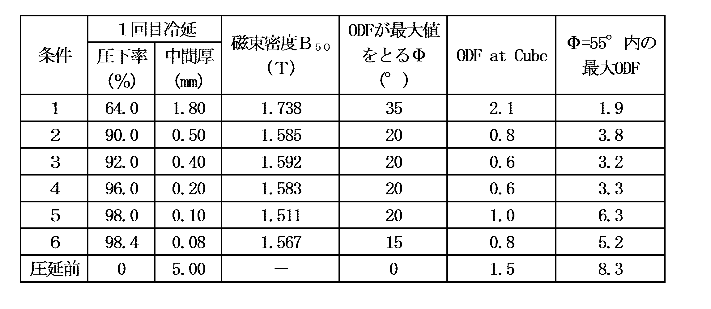
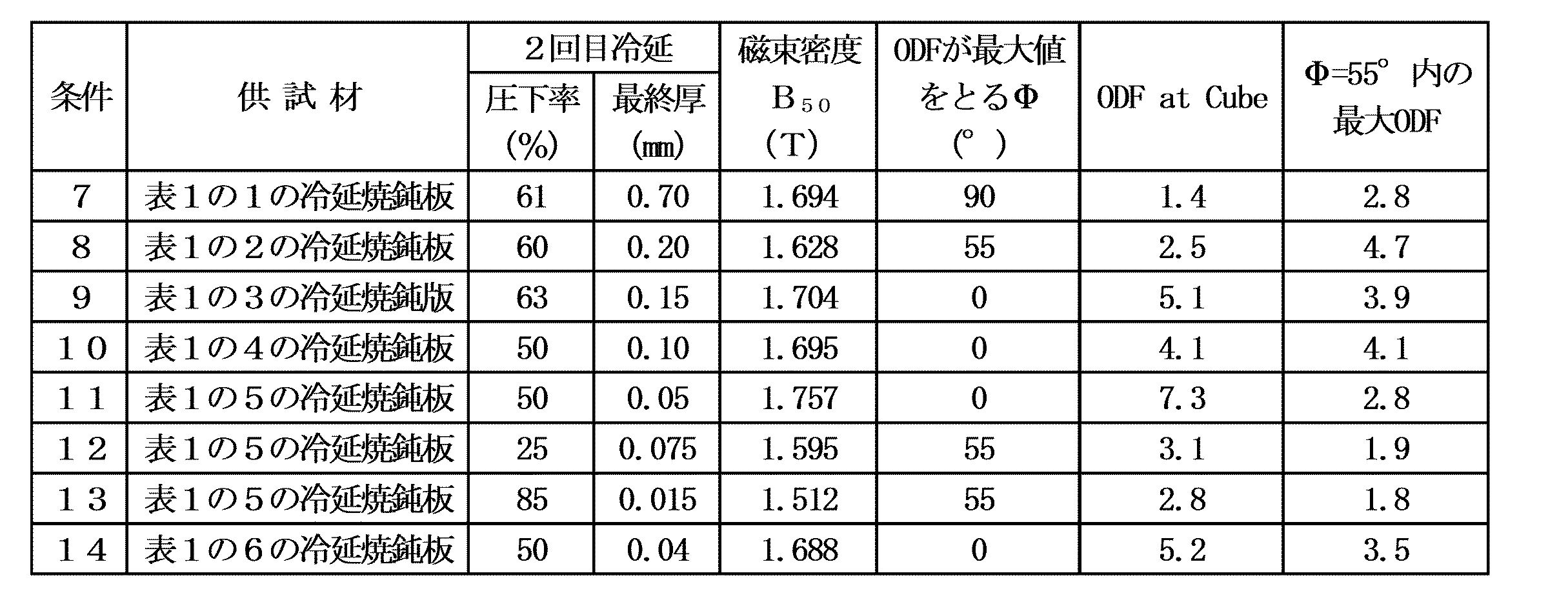
- Table 1 shows the results of the above measurements.
- the magnetic flux density decreased as the cold rolling reduction increased. This is probably because ⁇ 111 ⁇ , which adversely affects the magnetic properties, increased.
- a cold-rolled annealed sheet under conditions 3 to 6 (the first cold rolling reduction is 92% or more) in Table 1 is used as a base material (starting material), and conditions 9 to 11 and 14 in Table 2 (under the second cold rolling reduction 50, 63%), the steel sheet subjected to the second cold rolling and annealing has a maximum ODF value of ⁇ of 0 °, and a high frequency of 4.0 or more in the Cube orientation, which is preferable for improving the magnetic flux density. It was found that it was generated in
- % in the steel composition described below means % by mass.
- the C content in the product sheet is high, magnetic aging will occur and the magnetic properties will deteriorate, so the C content in the steel material is limited to 0.0050% or less. . Preferably, it is 0.0030% or less.
- Si 1.0-4.5% Si is an element that increases resistivity and is effective in reducing eddy current loss, so it is added in an amount of 1.0% or more. On the other hand, excessive addition embrittles the steel and impairs manufacturability (rollability), so the content is made 4.5% or less. Preferably, it is 2.0% or more and 4.0% or less.
- the Si content in the steel material is lower than the above range. 1.0 to 7.5% after siliconizing.
- the reason why the upper limit is set to 7.5% is that even if the steel becomes brittle due to the Si content, there is no subsequent rolling process in which plate cracks are likely to occur.
- the preferable upper limit is 7.0%.
- Mn 2.00% or less
- Mn is an element that increases specific resistance, but if added excessively, raw material costs increase, so the content is limited to 2.00% or less. From the viewpoint of reducing the adverse effect of MnS precipitation on iron loss, it is preferable to set Mn to 0.5% or less.
- P 0.10% or less While P has the effect of increasing the strength of the steel sheet and improving the punchability, it embrittles the steel sheet, so the upper limit is made 0.10%. Preferably, it is 0.05% or less.
- S 0.0040% or less S is 0.0040% or less because it forms MnS and adversely affects the magnetic properties. Preferably, it is 0.0030% or less.
- the steel material used for manufacturing the non-oriented electrical steel sheet of the present invention may further contain the following components in addition to the above components.
- Al 0.0001-2.0%
- Al is an element that increases resistivity and is an element that is effective in reducing iron loss.
- the upper limit is preferably 2.0% because the magnetic flux density decreases when the content is excessive. More preferably, it is 1.5% or less.
- N 0.003% or less N forms nitrides with Al and Si and degrades the magnetic properties, so the content is preferably 0.003% or less. More preferably, it is 0.002% or less. More preferably, it is 0.0009% or less.
- Ca 0.0005-0.010% Ca may be added in the range of 0.0005% to 0.010% because Ca fixes S by performing an appropriate heat treatment and suppresses the formation of fine S precipitates that are disadvantageous to magnetic properties.
- Cr 0.001-0.05% Cr increases the specific resistance and is advantageous in reducing iron loss, so it may be added in the range of 0.001% to 0.05%. However, excessive addition will lower the magnetic flux density.
- Cu 0.001-0.5%
- Cu may be added in the range of 0.001% to 0.5% because it fixes S by performing an appropriate heat treatment and suppresses the formation of fine S precipitates that are disadvantageous to magnetic properties.
- Sb 0.001-0.05% Like Sn, Sb segregates on the surface of the steel sheet during annealing, suppresses the penetration of nitrogen into the steel sheet, and suppresses the formation of nitrides that cause deterioration of magnetic properties. may be included. However, excessive addition increases raw material costs, so the content is preferably 0.05% or less. More preferably, it is 0.01% or less.
- Sn segregates on the surface of the steel sheet during annealing, suppresses the intrusion of nitrogen into the steel sheet, and suppresses the formation of nitrides that cause deterioration of magnetic properties.
- the content is preferably 0.05% or less. More preferably, it is 0.01% or less.
- B 0.0001 to 0.005% B forms nitrides by performing an appropriate heat treatment, and suppresses the formation of fine nitrides that are disadvantageous to magnetic properties.
- Zn 0.001-0.1%
- Zn has the effect of suppressing nitridation during final annealing, so when Zn is added, it is made 0.001% or more.
- Zn if added in excess of 0.1%, it forms sulfides and increases iron loss, so the content is limited to 0.1% or less. It is preferably 0.002% or more and 0.05% or less.
- Co 0.001-0.1%
- Co has the effect of improving the crystal orientation of steel, so when Co is added, it is made 0.001% or more. On the other hand, if added over 0.1%, the effect saturates and the addition cost increases, so the content is limited to 0.1% or less. It is preferably 0.002% or more and 0.05% or less.
- Mo, W 0.001-0.1% Both Mo and W are elements effective in suppressing surface defects (scouring) of the non-oriented electrical steel sheet of the present embodiment. Since the non-oriented electrical steel sheet of the present embodiment is a high-alloy steel and the surface is easily oxidized, the incidence of scabs due to surface cracks is high. Thus, the cracks can be suppressed. The above effect is not sufficient when the total content of Mo and W is less than 0.001%. be. Therefore, when Mo and W are added, the total content of Mo and W should be 0.001% or more and 0.1% or less. The total content of Mo and W is preferably in the range of 0.0050% to 0.050%. When Mo or W is contained alone, the content of Mo or W is 0.001% or more and 0.1% or less for the same reason as above.
- Ni 0.001-0.1% Since Ni increases the specific resistance and is advantageous in reducing iron loss, when Ni is added, the Ni content is set to 0.001% or more and 0.1% or less. However, excessive addition will lower the magnetic flux density.
- O Ti, Nb, V, Ta, Pb, As: 0.001-0.05% O, Ti, Nb, V, Ta, Pb, and As form carbonitrides, sulfides, and oxides that cause deterioration of magnetic properties, so when added, the content of each is 0.001% 0.05% or less.
- Mg, REM 0.001-0.05%
- Mg and REM have the effect of forming stable sulfides and improving grain growth.
- the total content of Mg and REM should be 0.001% or more.
- the total content is 0.001% or more and 0.05% or less.
- the content of Mg or REM is 0.001% or more and 0.05% or less for the same reason as above.
- Ge, Ga: 0.001-0.05% Ge and Ga have the effect of improving texture.
- the above effects are not sufficient when the total content of Ge and Ga is less than 0.001%.
- the total content exceeds 0.05%, the above effects are saturated and the alloy cost only increases. Therefore, when Ge and Ga are added, the total content should be 0.001% or more and 0.05% or less.
- the total content is 0.005% or more and 0.05% or less.
- the content of Ge or Ga is 0.001% or more and 0.05% or less for the same reason as above.
- each addition be less than 0.001%.
- the non-oriented electrical steel sheet of the present invention is characterized in that its crystal orientation preferentially has a plane orientation of ⁇ 100 ⁇ .
- ODF In the Orientation Distribution Function
- This ODF is obtained by analyzing by the EBSD method or the X-ray diffraction method after revealing the thickness center layer. In the case of the EBSD method, the ODF is calculated after including a sufficient number of crystal grains of at least 5000 or more in the analysis.
- the incomplete pole figures of the three surfaces ⁇ 110 ⁇ , ⁇ 200 ⁇ , and ⁇ 211 ⁇ are first measured, and based on these, the ADC method and the method using spherical harmonics are used.
- Calculate the ODF by The ODF is obtained on the Euler space represented by three angles ⁇ 1, ⁇ 2, and ⁇ (Bunge method). That is, it is possible to know the abundance of crystals having orientations of the Euler angles ( ⁇ 1, ⁇ , ⁇ 2) from the ODF.
- the ODF is originally defined in the space of ⁇ 1: 0 to 360°, ⁇ 2: 0 to 360°, ⁇ : 0 to 180°, but the crystal grains of the non-oriented electrical steel sheet of the present invention are Since it is a cubic crystal with high symmetry, ⁇ 1, ⁇ 2, and ⁇ can express the orientation space in the range of 0 to 90°.
- the preferred Cube orientation ODF intensity is 5.0 or more.
- the texture indicating the abundance of the crystals having the orientation of the Euler angles ( ⁇ 1, ⁇ , ⁇ 2) is displayed as the density in a three-dimensional space with the Euler angles ( ⁇ 1, ⁇ , ⁇ 2) taken as rectangular coordinates.
- the ODF intensity means the abundance of crystals having orientations of the Euler angles ( ⁇ 1, ⁇ , ⁇ 2), that is, the crystal orientation density.
- the intensity of is 4.0 or more.
- the crystal grain size of the present invention is calculated by, for example, the line segment method (JIS G0551) by EBSD method or optical microscopic observation from the surface of the sample that has been polished and etched after revealing the plate thickness center layer.
- the crystal grain size affects the magnetic domain structure, and if it is coarse, the high-frequency iron loss increases, so it is preferable that the crystal grain size is small.
- the average grain size of the primary recrystallized grains is generally 0.5 mm or less, but preferably 0.20 mm or less in the present invention.
- the slab adjusted to the chemical composition suitable for the present invention described above in the steelmaking process is preferably heated to a temperature of 1200° C. or less prior to hot rolling. If the temperature is higher than 1200° C., fine dispersion of MnS and AlN occurs in the process after hot rolling, which causes suppression of grain growth. More preferably, it is 1150° C. or less.
- the finish rolling temperature is preferably 700 to 900°C, and the coiling temperature is preferably 600°C or less. If the finishing temperature is lower than 700°C, the rolling load during hot rolling increases, while if it exceeds 900°C, it becomes difficult to control the shape of the steel sheet during hot rolling, which is not preferable. Further, if the coiling temperature exceeds 600° C. and is excessively high, fine AlN is dispersed and precipitated, which may impede grain growth during hot-rolled sheet annealing and finish annealing, which is not preferable.
- a preferable finished plate thickness is 3.8 mm or more. This is because if it is too thin, it will not be possible to apply a desired high reduction in the subsequent cold rolling process. Although there is no upper limit, it is preferable to set the thickness to 6 mm, because an excessively large thickness causes problems in manufacturability such as weldability.
- hot-rolled steel sheet is then cold-rolled, but prior to that, hot-rolled sheet annealing may be performed.
- hot-rolled sheet annealing By performing hot-rolled sheet annealing, better values are obtained in terms of magnetic properties than in the case of not performing hot-rolled sheet annealing, but there is also the demerit that the production cost increases.
- the first cold rolling must have a high rolling reduction, but when the rolling reduction is 95% or more, hot-rolled sheet annealing is performed to reduce the rolling load. Softening is preferred.
- the hot-rolled sheet annealing atmosphere may be a nitrogen atmosphere, but is preferably a hydrogen atmosphere or an Ar atmosphere. This is because when annealing is performed in a nitrogen atmosphere, nitrogen penetrates into the base iron and precipitates silicon nitride, which causes deterioration of magnetic properties.
- the soaking temperature for hot-rolled sheet annealing is preferably 750°C or higher, and the upper limit is preferably 1200°C.
- the hot-rolled sheet after hot-rolling or after hot-rolled sheet annealing is descaled by a method such as pickling with hydrochloric acid, and then cold-rolled twice by a cold-rolling method.
- the double cold rolling method is a cold rolling method in which an intermediate annealing step is interposed between two cold rollings.
- the rolling reduction of the first cold rolling must be 92% or more. If it is less than 92%, ⁇ 100 ⁇ oriented grains are not sufficiently formed after final annealing, which will be described later. Although there is no particular restriction on the upper limit of the rolling reduction, it is preferably 98% in order to avoid an excessive rolling load.
- the rolling temperature of the steel sheet in the first cold rolling is preferably 150°C or higher and 300°C or lower.
- the temperature is set to 150° C. or higher, deformation bands are formed in the steel sheet during cold rolling under high pressure. After subsequent intermediate annealing, more ⁇ 100 ⁇ oriented grains are formed from this deformation band.
- the intermediate annealing following the first cold rolling is preferably soaked at a temperature of 600°C or higher to recrystallize the rolling structure. More preferably, it is 900° C. or higher. The upper limit is preferably 1200°C.
- the atmosphere for the intermediate annealing is preferably a hydrogen atmosphere or an Ar atmosphere as in the hot-rolled sheet annealing.
- the rolling reduction of the second cold rolling following the intermediate annealing must be 30% or more and 80% or less. If it is less than 30%, the strain, which is the driving force for recrystallization, is not sufficiently accumulated, and crystal grains become excessively coarse due to strain-induced grain growth during annealing, increasing high-frequency iron loss. Preferably it is 40% or more. On the other hand, if it exceeds 80%, ⁇ 111 ⁇ oriented grains which are disadvantageous to the magnetic properties preferentially recrystallize from the vicinity of the grain boundary increase. Preferably, it is 65% or less.
- the rolling temperature of the steel sheet in the second cold rolling is preferably 50°C or higher and 150°C or lower.
- the temperature is preferably 50°C or higher and 150°C or lower.
- diffusion of C in the steel sheet is facilitated, and dislocations are fixed by C during cold rolling, thereby promoting the development of deformation bands in the steel strip. 100 ⁇ orientation grains are formed more.
- rolling at 150° C. or higher saturates the above effects and causes an excessive rolling load, so the rolling temperature is preferably 150° C. or lower.
- the final plate thickness after cold rolling that is, the plate thickness after the second cold rolling is preferably 0.20 mm or less. Since high-frequency iron loss increases when the plate thickness increases, the thinner the plate, the better. More preferably, it is 0.10 mm or less. On the other hand, if the thickness is excessively thin, not only will the cold rolling load increase and the productivity will decrease, but also the handling property of the steel sheet will be impaired, deformation such as bending will easily occur, and the magnetic properties will deteriorate.
- the lower limit is preferably 0.05 mm.
- the steel plate that has been cold-rolled to the final thickness is finally annealed, and an insulating coating is applied and baked to form it.
- the soaking temperature in the final annealing is preferably 700° C. or higher in order to recrystallize the rolled structure and obtain an average crystal grain size in the rolling direction of 0.20 mm or less.
- the upper limit temperature of the final annealing is preferably 1200°C. This is because if the temperature exceeds 1200° C., the equipment cost increases.
- the atmosphere for the final annealing is preferably a reducing atmosphere such as a hydrogen atmosphere or an Ar atmosphere, or a reduced pressure atmosphere of 10 kPa or less.
- the final annealing after the second cold rolling is set to less than 700 ° C., leaving a non-recrystallized structure to increase strength.
- the stator core may be subjected to stress relief annealing, which will be described later, to completely recrystallize and reduce iron loss.
- stress relief annealing which will be described later
- the definition of the crystal texture of the present invention is applied to the steel sheet after stress relief annealing.
- the formation of the coating may be performed separately from the final annealing, but in the present invention, the step of forming the insulating coating is also included in the final annealing step.
- the steel in the final annealing step, may be siliconized using a known method such as the CVD method or the PVD method to contain Si in the steel.
- a motor core is usually composed of a rotor core and a stator core. It is desirable that the magnetic steel sheet used for the rotor core have high strength in order to withstand centrifugal force due to high-speed rotation. On the other hand, the magnetic steel sheet used for the stator core desirably has high magnetic flux density and low core loss in order to achieve miniaturization and high output of the motor. Therefore, in the present invention, a rotor core material and a stator core material are obtained by processing the non-oriented electrical steel sheet obtained by the manufacturing method of the present invention described above into an iron core shape, and the rotor core is manufactured by laminating the above rotor core materials. The stator core is produced by stacking the above stator core materials and then performing strain relief annealing. A motor in which the rotor core and the stator core manufactured by the above method are incorporated into the motor core has excellent characteristics of high torque and high efficiency.
- the stress relief annealing is preferably performed at a temperature of 700°C or higher. If the temperature is less than 700° C., if a non-recrystallized structure remains in the steel sheet after finish annealing, it will be difficult to completely recrystallize it, and the strain during punching will not be removed. Moreover, the atmosphere for this stress relief annealing is preferably a non-oxidizing atmosphere.
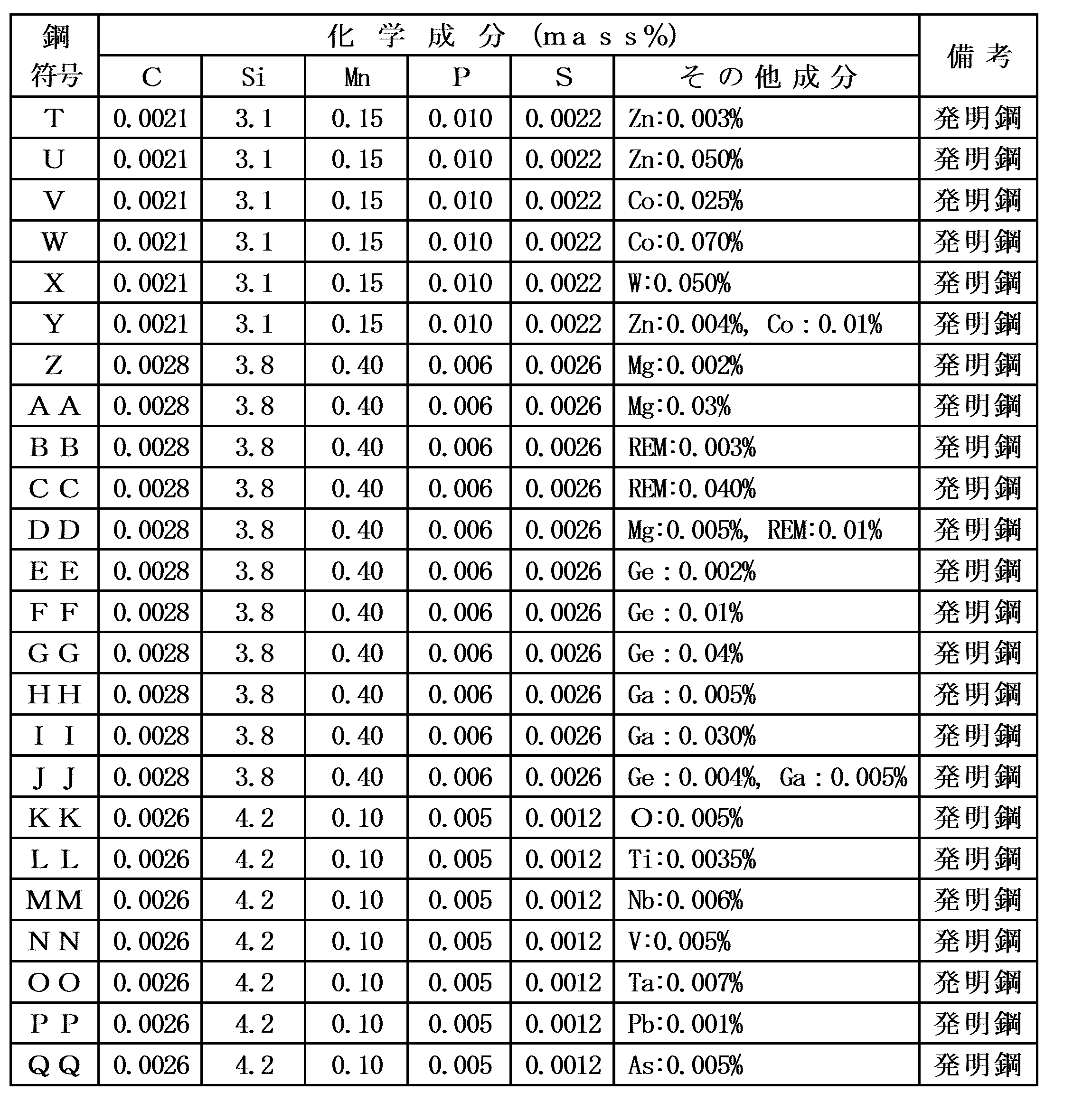
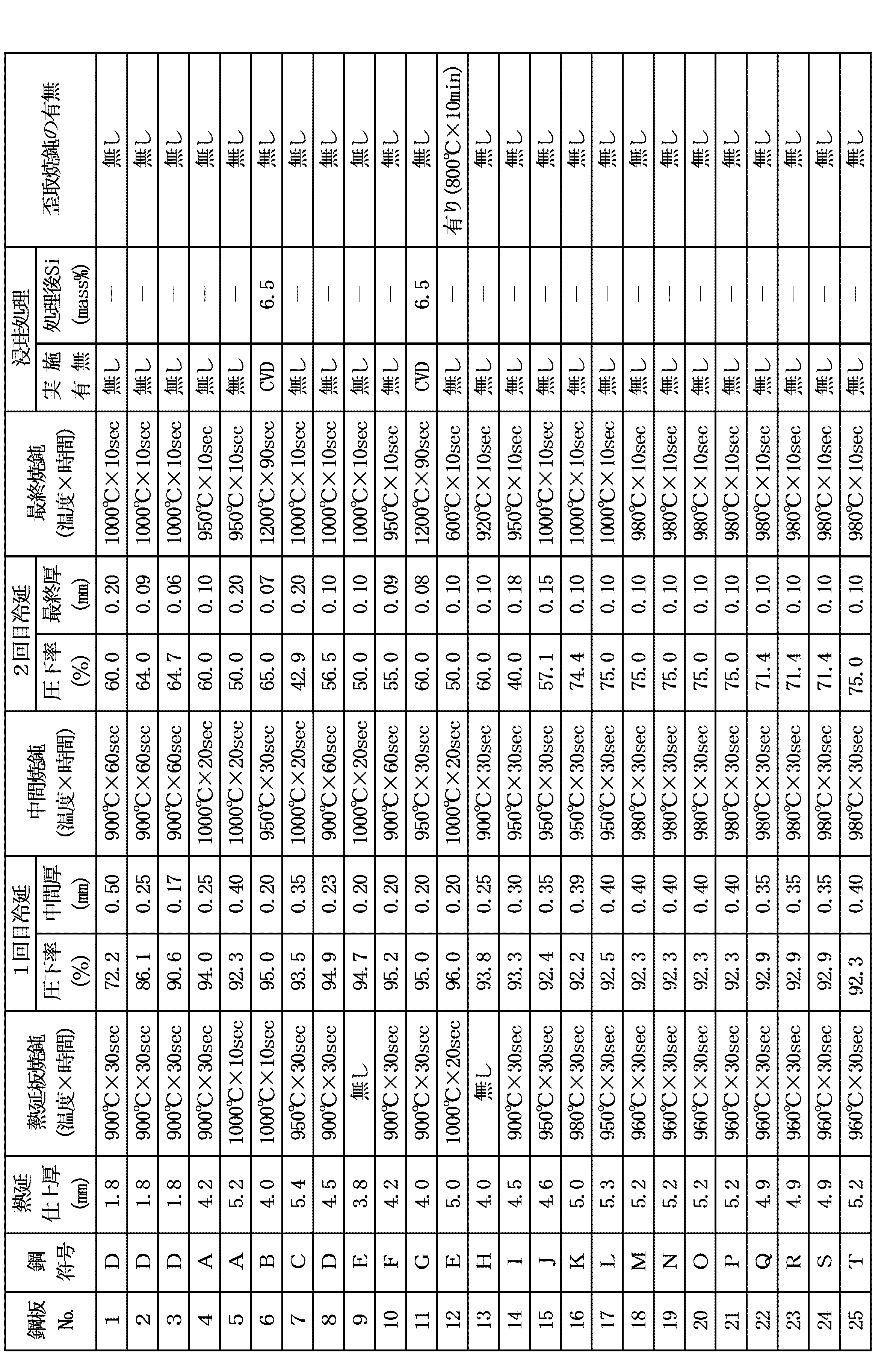
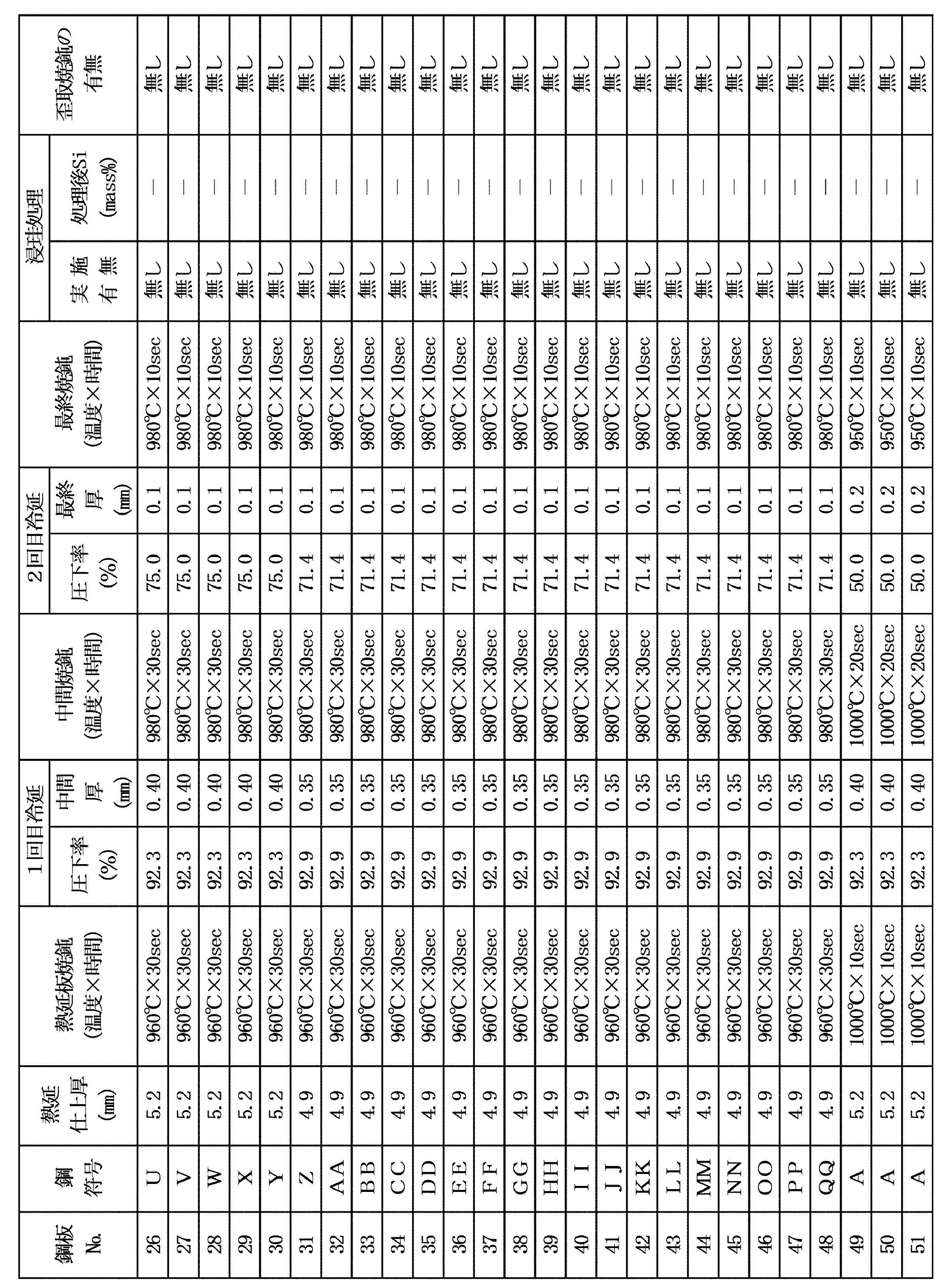
- the above slabs were heated to 1100°C and hot-rolled into hot-rolled sheets having the thicknesses shown in Tables 4-1 to 4-3.
- the finishing temperature for hot rolling was 1000°C to 900°C, and the coiling temperature was 600°C to 550°C.
- the hot-rolled sheet was subjected to hot-rolled sheet annealing under the conditions shown in Tables 4-1 to 4-3, then cold-rolled twice with intermediate annealing intervening, and finally annealed.
- Steel plate Some of the steel sheets were subjected to siliconizing treatment by the CVD method and diffusion annealing as the final annealing. At this time, hot-rolled sheet annealing was performed in a nitrogen atmosphere, and all other annealing was performed in an Ar atmosphere.
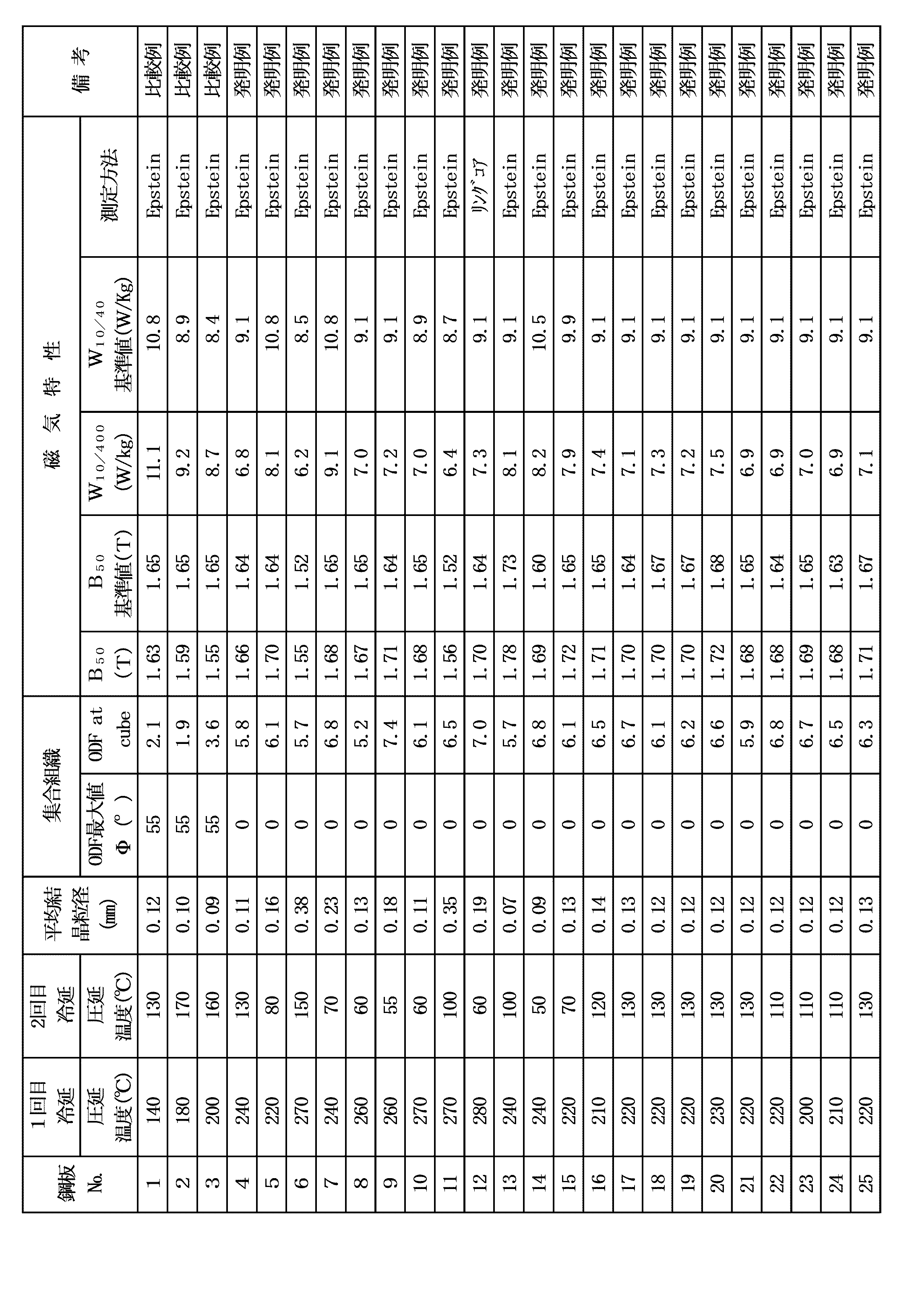
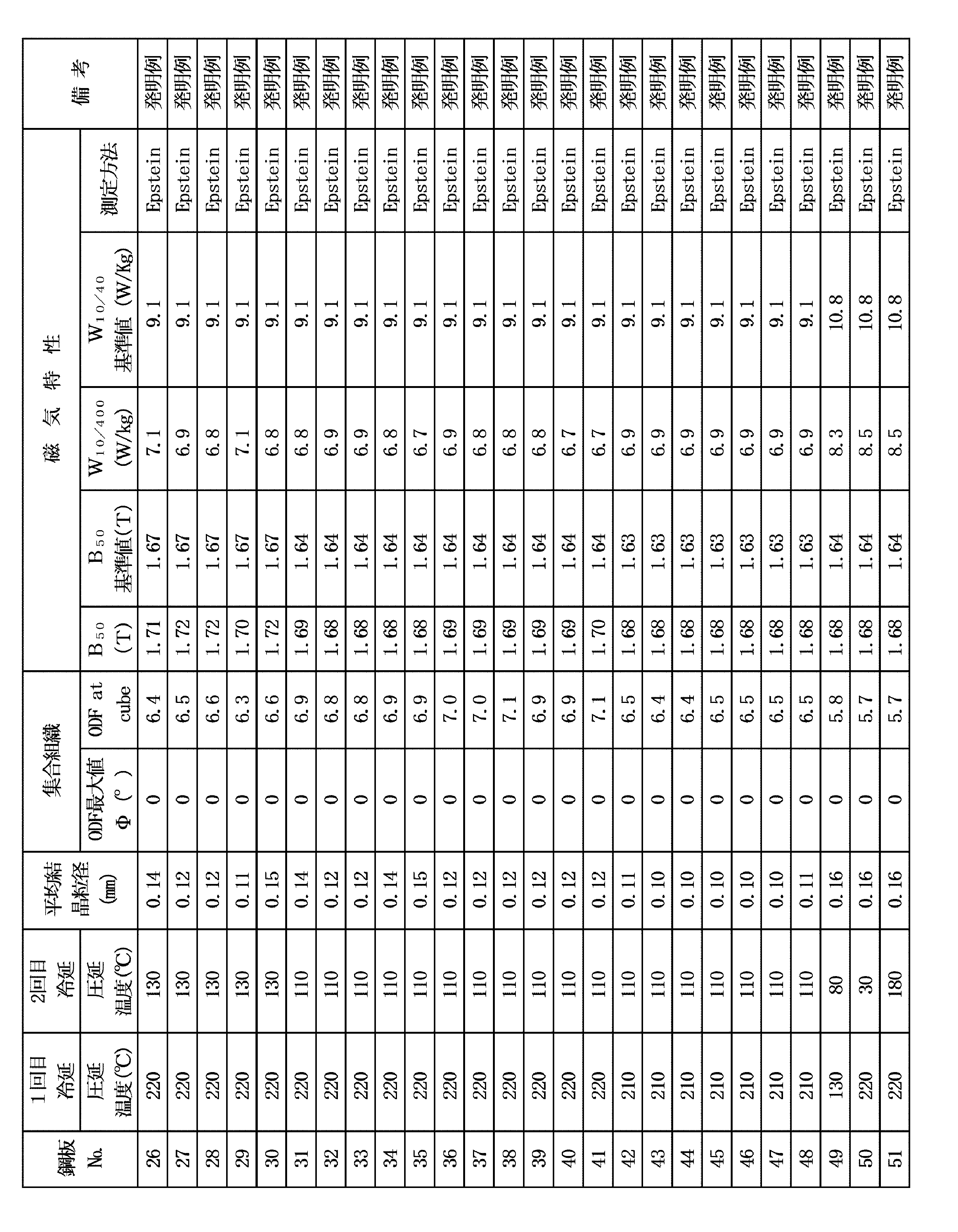
- the magnetic properties, average grain size and texture of the steel sheets after the final annealing were measured under the conditions described below.
- a test piece of 280 mm in length x 30 mm in width was cut out from each steel plate after the final annealing.
- the magnetic flux density B 50 and iron loss W 10/400 were measured by the Epstein test, and their average values were obtained.
- a ring with an outer diameter of 100 mm ⁇ and an inner diameter of 60 mm ⁇ was punched from the final annealed plate, laminated with an acrylic adhesive until the thickness reached 10 mm, and a ring core was produced. After applying stress relief annealing for ⁇ 10 min, the magnetic properties were measured.
- a test piece is cut from each steel plate after final annealing, chemically polished to reveal the thickness center layer, and the texture of the center layer surface is measured using X-rays.
- the crystal grain size was measured by the line segment method from the microscopic structure.
- non-oriented electrical steel sheet with high magnetic flux density and low high-frequency iron loss, and there is a possibility that this non-oriented electrical steel sheet can be applied to electrical equipment etc. that require small and high-speed rotating motors.
Landscapes
- Chemical & Material Sciences (AREA)
- Engineering & Computer Science (AREA)
- Materials Engineering (AREA)
- Mechanical Engineering (AREA)
- Metallurgy (AREA)
- Organic Chemistry (AREA)
- Physics & Mathematics (AREA)
- Thermal Sciences (AREA)
- Crystallography & Structural Chemistry (AREA)
- Electromagnetism (AREA)
- Manufacturing & Machinery (AREA)
- Power Engineering (AREA)
- Dispersion Chemistry (AREA)
- Soft Magnetic Materials (AREA)
- Manufacturing Of Steel Electrode Plates (AREA)
Abstract
Description
その結果、上記特許文献1に開示の技術では、減圧雰囲気での焼鈍によって、磁束密度B50や鉄損W15/100等、商用周波数域での磁気特性は優れているが、鉄損W10/400などの高周波域での鉄損は予期した以上に低減されないことがわかった。この原因を調査するため、得られた鋼板組織を観察した結果、結晶粒径のばらつきが非常に大きく、例えば、圧延方向の粒径で最小数mmから最大40mmの超粗大結晶粒まで混在し、平均結晶粒径が20mm以上にまで粗大化していた。高周波域での鉄損は、磁区構造の影響を強く受けることから、上記鉄損の上昇は、結晶粒の粗大化により、磁区サイズが大きくなったためであると考えられる。
[1]質量%で、C:0.0050%以下、Si:1.0~4.5%、Mn:2.00%以下、P:0.10%以下、S:0.0040%以下を含有し、残部がFeおよび不可避的不純物からなる成分組成を有し、板厚が0.20mm以下で、結晶集合組織を表現する、0≦φ1≦90°、φ2=45°、0≦Φ≦90°のオイラー空間内に示された板厚中心層の方位分布関数ODFにおいて、最大の強度がΦ=0°内にあり、φ1=45°、φ2=45°、Φ=0°である方位の強度が4.0以上の無方向性電磁鋼板である。
[2]上記の[1]において圧延方向の平均結晶粒径が0.20mm以下であることが好ましい。
[3]上記の[1]または[2]において、前記成分組成に加えてさらに、質量%で、
Al:0.0001~2.0%、N:0.003%以下、Ca:0.0005~0.010%、Cr:0.001~0.05%、Cu:0.001~0.5%、Sb:0.001~0.05%、Sn:0.001~0.05%、及びB:0.0001~0.005%のうちから選ばれる少なくとも1種を含有することができる。
[4]上記の[1]から[3]のいずれかにおいて、Siを1.0~7.5%の範囲で含有することができる。
[5]上記の[1]から[4]のいずれかにおいて、前記成分組成に加えてさらに、質量%で、Zn、Co、Mo、NiおよびWから選ばれる1種または2種以上を合計で0.001~0.1mass%の範囲で含有することができる。
[6] 上記の[1]から[5]のいずれかにおいて、前記成分組成に加えてさらに、質量%で、O、Mg、REM、Ti、Nb、V、Ta、Ge、Pb、AsおよびGaから選ばれる1種または2種以上を合計で0.001~0.05mass%の範囲で含有することができる。
Al:0.0001~2.0%、N:0.003%以下、Ca:0.0005~0.010%、Cr:0.001~0.05%、Cu:0.001~0.5%、Sb:0.001~0.05%、Sn:0.001~0.05%、及びB:0.0001~0.005%のうちから選ばれる少なくとも1種を含有し、残部がFeおよび不可避的不純物からなる成分組成を有する鋼素材を熱間圧延し、中間焼鈍を挟む2回の冷間圧延をした後、最終焼鈍を施す無方向性電磁鋼板の製造方法であって、1回目の冷間圧延の圧下率を92%以上とし、2回目の冷間圧延の圧下率を30%以上80%以下とする無方向性電磁鋼板の製造方法である。
[8]上記の[7]において、前記熱間圧延から前記1回目の冷間圧延の間に、熱延板焼鈍を施すことができる。
[9]上記の[7]又は[8]において、前記冷間圧延時において、前記1回目の冷間圧延の圧延温度を150~300℃、前記2回目の冷間圧延の圧延温度を50~150℃とすることができる。
[10]上記の[7]から[9]のいずれかにおいて、前記冷間圧延後に浸珪処理を施し、Siを全板厚平均で最大7.5%まで含有させることができる。
しかし、上記実験結果では、1回目の冷間圧延で強圧下し、2回目の冷間圧延で軽圧下の圧延をして製品厚に仕上げる新たなプロセスを採用することで、従来に無い磁気特性、特に高周波域での鉄損低減に有利な集合組織が得られることを知見した。
製品板中に含まれるCの含有量が高いと、磁気時効を起こし、磁気特性が劣化することから、鋼素材中に含まれるCは0.0050%以下に制限する。好ましくは、0.0030%以下である。
Siは、比抵抗増大元素であり、渦電流損を低減するのに有効であるため、1.0%以上添加する。一方、過度に添加すると鋼を脆化し、製造性(圧延性)を損なうため、4.5%以下とする。好ましくは、2.0%以上4.0%以下である。
Mnは、比抵抗増大元素であるが、過度に添加すると原料コストが増大するため2.00%以下に制限する。なお、MnS析出による鉄損への悪影響を低減する観点からは、Mnを0.5%以下とするのが好ましい。
Pは、鋼板を高強度化し、打ち抜き性を改善する効果がある一方、鋼板を脆化するため、上限を0.10%とする。好ましくは、0.05%以下である。
Sは、MnSを形成して磁気特性に悪影響を及ぼすことから0.0040%以下とする。好ましくは、0.0030%以下である。
Al:0.0001~2.0%
Alは、比抵抗増大元素であり、低鉄損化に有効な元素である。一方、過度に含有させると磁束密度が低下するため、上限は2.0%とするのが好ましい。より好ましくは、1.5%以下である。
Nは、Al、Siと窒化物を形成し、磁気特性を劣化させるため、0.003%以下とするのが好ましい。より好ましくは、0.002%以下である。さらに好ましくは、0.0009%以下である。
Caは、適切な熱処理を施すことによってSを固定し、磁気特性に不利な微細S析出物の形成を抑制することから、0.0005%から0.010%の範囲で添加してもよい。
Crは、比抵抗を増大し、鉄損低減に有利であることから、0.001%から0.05%の範囲で添加してもよい。ただし、過度の添加は磁束密度が低下する。
Cuは、適切な熱処理を施すことによってSを固定し、磁気特性に不利な微細S析出物の形成を抑制することから、0.001%から0.5%の範囲で添加してもよい。
Sbは、Snと同様に焼鈍時に鋼板表面に偏析して、窒素が鋼板内部へ侵入するのを抑制し、磁気特性の劣化の原因となる窒化物の形成を抑制することから0.001%以上含有させてもよい。ただし、過度に添加すると、原料コストが増大するため、0.05%以下とするのが好ましい。より好ましくは、0.01%以下である。
Snは、焼鈍中に鋼板の表面に偏析して、窒素が鋼板内部へ侵入するのを抑制し、磁気特性の劣化の原因となる窒化物の形成を抑制することから0.001%以上含有させてもよい。ただし、過度に添加すると、原料コストが増大するため、0.05%以下とするのが好ましい。より好ましくは、0.01%以下である。
Bは、適切な熱処理を施すことによって窒化物を形成し、磁気特性に不利な微細窒化物の形成を抑制することから、0.0001%以上0.005%以下で添加してもよい。
Znは、仕上焼鈍時の窒化を抑制する効果があるため、Znを添加する場合0.001%以上とする。一方、0.1%を超えて添加すると、硫化物を形成して鉄損を増加させるため、0.1%以下に制限する。好ましくは0.002%以上0.05%以下である。
Coは、鋼の結晶方位を改善する効果があるため、Coを添加する場合、0.001%以上とする。一方、0.1%を超えて添加すると、効果が飽和し、かつ添加コストも増大するため、0.1%以下に制限する。好ましくは0.002%以上0.05%以下である。
Mo、Wは、いずれも本実施形態の無方向性電磁鋼板の表面欠陥(ヘゲ)を抑制するのに有効な元素である。本実施形態の無方向性電磁鋼板は、高合金鋼で表面が酸化され易いため、表面割れに起因するヘゲの発生率が高いが、高温強度を高める元素であるMo、Wを微量添加することで、上記割れを抑制することができる。上記効果は、Mo、Wの合計含有量が0.001%を下回ると十分ではなく、一方、0.1%を超えて添加しても、上記効果が飽和し、合金コストが上昇するだけである。よって、Mo、Wを添加する場合はMoとWの合計含有量は0.001%以上0.1%以下とする。好ましくはMoとWの合計含有量は0.0050%以上0.050%以下の範囲である。なお、Mo又はWを単独で含有する場合は、上記と同様な理由で、Mo又はWの含有量は0.001%以上0.1%以下である。
Niは、比抵抗を増大し、鉄損低減に有利であることから、Niを添加する場合、Ni含有量は0.001%以上0.1%以下とする。ただし、過度の添加は磁束密度が低下する。
O、Ti、Nb、V、Ta、Pb、およびAsは、磁気特性劣化の原因となる炭窒化物、硫化物、酸化物を形成するため、添加する場合、それぞれの含有量は0.001%以上0.05%以下とする。
MgおよびREMは、安定な硫化物を形成し、粒成長性を改善する効果がある。上記効果を得るためには、MgおよびREMは合計で0.001%以上とする。しかし、0.05%を超えて添加しても、上記効果は飽和する。よって、MgおよびREMを添加する場合は、合計で0.001%以上0.05%以下とする。なお、Mg又はREMを単独で含有する場合は、上記と同様な理由で、Mg又はREMの含有量は0.001%以上0.05%以下である。
GeおよびGaは、集合組織を改善する効果がある。上記効果は、Ge、Gaの合計含有量が0.001%を下回ると十分ではなく、一方、0.05%を超えても、上記効果が飽和し、合金コストが上昇するだけである。よって、GeおよびGaを添加する場合、合計含有量は0.001%以上0.05%以下とする。好ましくは、合計含有量は0.005%以上0.05%以下である。なお、Ge又はGaを単独で含有する場合は、上記と同様な理由で、Ge又はGaの含有量は0.001%以上0.05%以下である。
<結晶方位>
本発明の無方向性電磁鋼板は、その結晶方位が{100}の面方位を優先的に有することを特徴とする。ここで、上記{100}の面方位を優先的に有するとは、0≦φ1≦90°、φ2=45°、0≦Φ≦90°のオイラー空間内に示された方位分布関数(ODF:Orientation Distribution Function)において、最大の強度がΦ=0°内にあることと定義する。このODFは、板厚中心層を現出した後、EBSD法やX線回折法によって解析することで得られる。EBSD法の場合には、少なくとも5000個以上の十分な数の結晶粒を解析に含んだ上でODFを計算する。X線回折法の場合には、初めに{110}、{200}、{211}の3面の不完全極点図を測定し、これらをもとに、ADC法や球面調和関数を使った方法によってODFを計算する。ODFは、φ1、φ2、Φの3つの角度(Bunge法)で表されるオイラー空間上に求める。すなわち、ODFからオイラー角(φ1、Φ、φ2)の方位を持つ結晶の存在量を知ることができる。
上記のBunge法では、本来、φ1:0~360°、φ2:0~360°、Φ:0~180°の空間でODFを定義するが、本発明の無方向性電磁鋼板の結晶粒は、対称性の高い立方晶であることから、φ1、φ2、Φとも0~90°で方位空間を表現することができる。
最大の強度がΦ=0°内とは、φ2=45°におけるφ1-Φの集合組織図において、Φ=0°で最大のODF強度を有する場合をいう。また、φ1=45°、φ2=45°、Φ=0°におけるODF強度が4以上とは、φ2=45°におけるφ1-Φの集合組織図において、φ1=45°、Φ=0°における方位の強度が4.0以上であることをいう。
本発明の結晶粒径は、板厚中心層を現出し、研磨・エッチングした試料表面からEBSD法や光学顕微鏡観察により、例えば線分法(JIS G0551)で算出する。結晶粒径は、磁区構造に影響を及ぼし、粗大であると高周波鉄損が増大するため、小さい方が好ましい。1次再結晶粒の平均結晶粒径は一般的に0.5mm以下であるが、本発明では0.20mm以下であることが好ましい。
製鋼工程において上記に説明した本発明に適合する成分組成に調整したスラブは、熱間圧延に先立って1200℃以下の温度に加熱するのが好ましい。1200℃より高いと、熱延後の工程でMnSやAlNの微細分散が生じて、粒成長を抑制する原因となる。より好ましくは、1150℃以下である。
ここで、本発明においては、上記1回目の冷間圧延の圧下率は92%以上とする必要がある。92%未満では、後述する最終焼鈍後で{100}の方位粒が十分に形成されない。なお、圧下率の上限については、特に制約は無いが、過度な圧延負荷となるのを避けるため、98%とするのが好ましい。

磁気特性は、最終焼鈍後の各鋼板から長さ280mm×幅30mmの試験片を、長さ方向が、圧延方向のものと、圧延直交方向のものをそれぞれ各2枚切り出して4枚1セットを採取し、エプスタイン試験で磁束密度B50と鉄損W10/400を測定し、それらの平均値を求めた。なお、一部の鋼板については、最終焼鈍板から、外径100mmφ、内径60mmφのリングを打抜き、厚さが10mmになるまでアクリル系接着剤で接着して積層し、リングコアを作製し、800℃×10minの歪取焼鈍を施した後、磁気特性を測定した。
集合組織及び平均結晶粒径は、最終焼鈍後の各鋼板から試験片を切り出し、化学研磨して板厚中心層を現出し、上記中心層面について、集合組織はX線を用いて、また、平均結晶粒径は顕微鏡の組織から線分法にて測定した。

B50基準値=1.78-(Si×0.04+Mn×0.15)
W10/400基準値=17.6×t+7.3
ここで、上記式中のSi,Mnはそれぞれの成分の含有量(mass%)、tは鋼板板厚(mm)である。
2回冷延法を採用し、1回目の冷延圧下率を92%以上とした発明例(No.4~51)は、1回目の冷延圧下率が72.2~90.6%の比較例(No.1~3)と比べ、良好な高周波鉄損が得られた。これは、ODF解析値より、発明例(No.4~51)ではCube方位が発達し、比較例(No.1~3)では、Cube方位よりも磁気特性上不利な{111}方位が発達したためと考えられる。
また、平均結晶粒径が0.20mm以下の発明例(No.4、5、8、9、10、13~51)の高周波鉄損W10/400は6.8~8.5W/kgであるのに対して、平均結晶粒径が0.23mmの発明例(No.7)の高周波鉄損W10/400は9.1W/kgであることから、平均結晶粒径を0.20mm以下とすることにより高周波鉄損がさらに改善されることがわかる。

Claims (11)
- 質量%で、
C:0.0050%以下、
Si:1.0~4.5%、
Mn:2.00%以下、
P:0.10%以下、
S:0.0040%以下を含有し、
残部がFeおよび不可避的不純物からなる成分組成を有し、
板厚が0.20mm以下で、
結晶集合組織を表現する、0≦φ1≦90°、φ2=45°、0≦Φ≦90°のオイラー空間内に示された板厚中心層の方位分布関数ODFにおいて、最大の強度がΦ=0°内にあり、φ1=45°、φ2=45°、Φ=0°である方位の強度が4.0以上である無方向性電磁鋼板。 - 圧延方向の平均結晶粒径が0.20mm以下であることを特徴とする請求項1に記載の無方向性電磁鋼板。
- 前記成分組成に加えてさらに、質量%で、
Al:0.0001~2.0%、N:0.003%以下、Ca:0.0005~0.010%、Cr:0.001~0.05%、Cu:0.001~0.5%、Sb:0.001~0.05%、Sn:0.001~0.05%、及びB:0.0001~0.005%のうちから選ばれる少なくとも1種を含有することを特徴とする請求項1又は2に記載の無方向性電磁鋼板。 - Siを1.0~7.5%の範囲で含有することを特徴とする請求項1から3のいずれか1項に記載の無方向性電磁鋼板。
- 前記成分組成に加えてさらに、質量%で、Zn、Co、Mo、NiおよびWから選ばれる1種または2種以上を合計で0.001~0.1mass%の範囲で含有することを特徴とする請求項1から4のいずれか1項に記載の無方向性電磁鋼板。
- 前記成分組成に加えてさらに、質量%で、O、Mg、REM、Ti、Nb、V、Ta、Ge、Pb、AsおよびGaから選ばれる1種または2種以上を合計で0.001~0.05mass%の範囲で含有することを特徴とする請求項1から5のいずれか1項に記載の無方向性電磁鋼板。
- 質量%で、
C:0.0050%以下、
Si:1.0~4.5%、
Mn:2.00%以下、
P:0.10%以下、
S:0.0040%以下を含有し、
さらに、任意選択的に、
Al:0.0001~2.0%、N:0.003%以下、Ca:0.0005~0.010%、Cr:0.001~0.05%、Cu:0.001~0.5%、Sb:0.001~0.05%、Sn:0.001~0.05%、及びB:0.0001~0.005%のうちから選ばれる少なくとも1種を含有し、
残部がFeおよび不可避的不純物からなる成分組成を有する
鋼素材を熱間圧延し、中間焼鈍を挟む2回の冷間圧延をした後、最終焼鈍を施す無方向性電磁鋼板の製造方法であって、
1回目の冷間圧延の圧下率を92%以上とし、2回目の冷間圧延の圧下率を30%以上80%以下とする無方向性電磁鋼板の製造方法。 - 前記熱間圧延から前記1回目の冷間圧延の間に、熱延板焼鈍を施すことを特徴とする請求項7に記載の無方向性電磁鋼板の製造方法。
- 前記冷間圧延時において、前記1回目の冷間圧延の圧延温度を150~300℃、前記2回目の冷間圧延の圧延温度を50~150℃とすることを特徴とする請求項7または8に記載の無方向性電磁鋼板の製造方法。
- 前記冷間圧延後に浸珪処理を施し、Siを全板厚平均で最大7.5%まで含有させることを特徴とする請求項7から9のいずれか1項に記載の無方向性電磁鋼板の製造方法。
- 請求項7から9のいずれか1項に記載の方法で製造した無方向性電磁鋼板からロータコアとステータコアからなるモータコアを作製した後、ステータコアに歪取焼鈍を施すことを特徴とするモータコアの製造方法。
Priority Applications (6)
| Application Number | Priority Date | Filing Date | Title |
|---|---|---|---|
| CN202280074304.5A CN118159677A (zh) | 2021-11-17 | 2022-10-31 | 无取向性电磁钢板及其制造方法以及电动机铁芯的制造方法 |
| MX2024005824A MX2024005824A (es) | 2021-11-17 | 2022-10-31 | Lamina de acero electrico no orientado y metodo para producirla, y metodo para producir el nucleo de un motor. |
| KR1020247016063A KR20240074010A (ko) | 2021-11-17 | 2022-10-31 | 무방향성 전자 강판과 그의 제조 방법 그리고 모터 코어의 제조 방법 |
| JP2023506199A JP7614572B2 (ja) | 2021-11-17 | 2022-10-31 | 無方向性電磁鋼板とその製造方法並びにモータコアの製造方法 |
| US18/709,957 US20250014793A1 (en) | 2021-11-17 | 2022-10-31 | Non-oriented electrical steel sheet and method for producing same, and method for producing motor core |
| EP22895421.0A EP4400622A4 (en) | 2021-11-17 | 2022-10-31 | NON-ORIENTED ELECTRICAL STEEL SHEET AND PRODUCTION METHOD THEREOF, AND PRODUCTION METHOD FOR MOTOR CORES |
Applications Claiming Priority (2)
| Application Number | Priority Date | Filing Date | Title |
|---|---|---|---|
| JP2021186845 | 2021-11-17 | ||
| JP2021-186845 | 2021-11-17 |
Publications (1)
| Publication Number | Publication Date |
|---|---|
| WO2023090138A1 true WO2023090138A1 (ja) | 2023-05-25 |
Family
ID=86396865
Family Applications (1)
| Application Number | Title | Priority Date | Filing Date |
|---|---|---|---|
| PCT/JP2022/040677 Ceased WO2023090138A1 (ja) | 2021-11-17 | 2022-10-31 | 無方向性電磁鋼板とその製造方法並びにモータコアの製造方法 |
Country Status (8)
| Country | Link |
|---|---|
| US (1) | US20250014793A1 (ja) |
| EP (1) | EP4400622A4 (ja) |
| JP (1) | JP7614572B2 (ja) |
| KR (1) | KR20240074010A (ja) |
| CN (1) | CN118159677A (ja) |
| MX (1) | MX2024005824A (ja) |
| TW (1) | TWI830492B (ja) |
| WO (1) | WO2023090138A1 (ja) |
Cited By (3)
| Publication number | Priority date | Publication date | Assignee | Title |
|---|---|---|---|---|
| CN116790999A (zh) * | 2023-07-05 | 2023-09-22 | 张家港扬子江冷轧板有限公司 | 一种磁各向异性低的高牌号无取向硅钢及其制备方法 |
| WO2026034003A1 (ja) * | 2024-08-09 | 2026-02-12 | Jfeスチール株式会社 | 無方向性電磁鋼板 |
| WO2026034002A1 (ja) * | 2024-08-09 | 2026-02-12 | Jfeスチール株式会社 | 無方向性電磁鋼板 |
Families Citing this family (2)
| Publication number | Priority date | Publication date | Assignee | Title |
|---|---|---|---|---|
| WO2025230003A1 (ja) | 2024-05-02 | 2025-11-06 | 日本製鉄株式会社 | 無方向性電磁鋼板、モータコアおよびモータ |
| KR20260037677A (ko) * | 2024-09-09 | 2026-03-18 | 현대제철 주식회사 | 무방향성 전기강판 및 무방향성 전기강판 제조 방법 |
Citations (9)
| Publication number | Priority date | Publication date | Assignee | Title |
|---|---|---|---|---|
| JP2001131642A (ja) | 1999-11-02 | 2001-05-15 | Nkk Corp | 磁気特性に優れた無方向性電磁鋼板の製造方法及び磁気特性に優れた無方向性電磁鋼板 |
| JP2008106367A (ja) | 2007-11-19 | 2008-05-08 | Jfe Steel Kk | 二方向性電磁鋼板 |
| JP2012036454A (ja) * | 2010-08-09 | 2012-02-23 | Sumitomo Metal Ind Ltd | 無方向性電磁鋼板およびその製造方法 |
| CN104480386A (zh) * | 2014-11-27 | 2015-04-01 | 武汉钢铁(集团)公司 | 高速电机用0.2mm厚无取向硅钢及生产方法 |
| JP2017106101A (ja) | 2015-12-04 | 2017-06-15 | Jfeスチール株式会社 | 無方向性電磁鋼板およびその製造方法 |
| CN107245644A (zh) * | 2017-05-10 | 2017-10-13 | 东北大学 | 基于薄带连铸高磁感、低铁损薄规格无取向硅钢制备方法 |
| WO2020204107A1 (ja) * | 2019-04-03 | 2020-10-08 | 日本製鉄株式会社 | 電磁鋼板およびその製造方法 |
| JP6767687B1 (ja) * | 2019-01-24 | 2020-10-14 | Jfeスチール株式会社 | 無方向性電磁鋼板とその製造方法 |
| JP2020180347A (ja) * | 2019-04-25 | 2020-11-05 | Jfeスチール株式会社 | 電磁鋼板およびその製造方法 |
Family Cites Families (10)
| Publication number | Priority date | Publication date | Assignee | Title |
|---|---|---|---|---|
| JPH03120316A (ja) * | 1989-10-02 | 1991-05-22 | Sumitomo Metal Ind Ltd | 無方向性電磁鋼板の製造方法 |
| JP4258050B2 (ja) * | 1998-12-09 | 2009-04-30 | Jfeスチール株式会社 | 高珪素鋼板の製造方法 |
| JP6432173B2 (ja) * | 2014-06-17 | 2018-12-05 | 新日鐵住金株式会社 | 全周の磁気特性が良好な無方向性電磁鋼板 |
| JP2017040002A (ja) * | 2015-08-21 | 2017-02-23 | 日本金属株式会社 | 高周波用無方向性電磁鋼板およびその製造方法 |
| JP6658338B2 (ja) * | 2016-06-28 | 2020-03-04 | 日本製鉄株式会社 | 占積率に優れる電磁鋼板およびその製造方法 |
| JP6866935B2 (ja) * | 2018-10-31 | 2021-04-28 | Jfeスチール株式会社 | 無方向性電磁鋼板の製造方法 |
| KR102751545B1 (ko) * | 2019-11-15 | 2025-01-10 | 닛폰세이테츠 가부시키가이샤 | 무방향성 전자 강판의 제조 방법 |
| WO2021117325A1 (ja) * | 2019-12-09 | 2021-06-17 | Jfeスチール株式会社 | 無方向性電磁鋼板とモータコアならびにそれらの製造方法 |
| US12348079B2 (en) * | 2019-12-16 | 2025-07-01 | Jfe Steel Corporation | Motor core and method of manufacturing the same |
| US20230106818A1 (en) * | 2020-04-10 | 2023-04-06 | Nippon Steel Corporation | Non-oriented electrical steel sheet, core, cold-rolled steel sheet, method for manufacturing non-oriented electrical steel sheet, and method for manufacturing cold-rolled steel sheet |
-
2022
- 2022-10-31 US US18/709,957 patent/US20250014793A1/en active Pending
- 2022-10-31 EP EP22895421.0A patent/EP4400622A4/en active Pending
- 2022-10-31 MX MX2024005824A patent/MX2024005824A/es unknown
- 2022-10-31 KR KR1020247016063A patent/KR20240074010A/ko active Pending
- 2022-10-31 JP JP2023506199A patent/JP7614572B2/ja active Active
- 2022-10-31 CN CN202280074304.5A patent/CN118159677A/zh active Pending
- 2022-10-31 WO PCT/JP2022/040677 patent/WO2023090138A1/ja not_active Ceased
- 2022-11-10 TW TW111142876A patent/TWI830492B/zh active
Patent Citations (9)
| Publication number | Priority date | Publication date | Assignee | Title |
|---|---|---|---|---|
| JP2001131642A (ja) | 1999-11-02 | 2001-05-15 | Nkk Corp | 磁気特性に優れた無方向性電磁鋼板の製造方法及び磁気特性に優れた無方向性電磁鋼板 |
| JP2008106367A (ja) | 2007-11-19 | 2008-05-08 | Jfe Steel Kk | 二方向性電磁鋼板 |
| JP2012036454A (ja) * | 2010-08-09 | 2012-02-23 | Sumitomo Metal Ind Ltd | 無方向性電磁鋼板およびその製造方法 |
| CN104480386A (zh) * | 2014-11-27 | 2015-04-01 | 武汉钢铁(集团)公司 | 高速电机用0.2mm厚无取向硅钢及生产方法 |
| JP2017106101A (ja) | 2015-12-04 | 2017-06-15 | Jfeスチール株式会社 | 無方向性電磁鋼板およびその製造方法 |
| CN107245644A (zh) * | 2017-05-10 | 2017-10-13 | 东北大学 | 基于薄带连铸高磁感、低铁损薄规格无取向硅钢制备方法 |
| JP6767687B1 (ja) * | 2019-01-24 | 2020-10-14 | Jfeスチール株式会社 | 無方向性電磁鋼板とその製造方法 |
| WO2020204107A1 (ja) * | 2019-04-03 | 2020-10-08 | 日本製鉄株式会社 | 電磁鋼板およびその製造方法 |
| JP2020180347A (ja) * | 2019-04-25 | 2020-11-05 | Jfeスチール株式会社 | 電磁鋼板およびその製造方法 |
Non-Patent Citations (2)
| Title |
|---|
| GEORGE W. WIENER: "Metallurgy of oriented silicon steels", JOURNAL OF APPLIED PHYSICS, vol. 35, no. 3, 1964, pages 856 - 860 |
| See also references of EP4400622A4 |
Cited By (4)
| Publication number | Priority date | Publication date | Assignee | Title |
|---|---|---|---|---|
| CN116790999A (zh) * | 2023-07-05 | 2023-09-22 | 张家港扬子江冷轧板有限公司 | 一种磁各向异性低的高牌号无取向硅钢及其制备方法 |
| WO2026034003A1 (ja) * | 2024-08-09 | 2026-02-12 | Jfeスチール株式会社 | 無方向性電磁鋼板 |
| WO2026034002A1 (ja) * | 2024-08-09 | 2026-02-12 | Jfeスチール株式会社 | 無方向性電磁鋼板 |
| JP7831711B1 (ja) * | 2024-08-09 | 2026-03-17 | Jfeスチール株式会社 | 無方向性電磁鋼板 |
Also Published As
| Publication number | Publication date |
|---|---|
| US20250014793A1 (en) | 2025-01-09 |
| KR20240074010A (ko) | 2024-05-27 |
| EP4400622A4 (en) | 2025-01-08 |
| TW202321477A (zh) | 2023-06-01 |
| MX2024005824A (es) | 2024-05-28 |
| CN118159677A (zh) | 2024-06-07 |
| EP4400622A1 (en) | 2024-07-17 |
| JPWO2023090138A1 (ja) | 2023-05-25 |
| TWI830492B (zh) | 2024-01-21 |
| JP7614572B2 (ja) | 2025-01-16 |
Similar Documents
| Publication | Publication Date | Title |
|---|---|---|
| TWI820337B (zh) | 無方向性電磁鋼板的製造方法與馬達鐵芯的製造方法、以及馬達鐵芯 | |
| EP3859032B1 (en) | Non-oriented electrical steel sheet and method for producing same, and motor core and method for producing same | |
| JP7614572B2 (ja) | 無方向性電磁鋼板とその製造方法並びにモータコアの製造方法 | |
| EP3358027B1 (en) | Non-oriented electromagnetic steel sheet and manufacturing method of same | |
| WO2018221126A1 (ja) | 無方向性電磁鋼板とその製造方法 | |
| EP3533890A1 (en) | Nonoriented electromagnetic steel sheet and method for producing same | |
| WO2018135414A1 (ja) | 無方向性電磁鋼板およびその製造方法 | |
| WO2013058239A1 (ja) | 方向性電磁鋼板およびその製造方法 | |
| WO2013080891A1 (ja) | 無方向性電磁鋼板の製造方法 | |
| WO2004013365A1 (ja) | 無方向性電磁鋼板、回転機用部材および回転機 | |
| JP2020509184A (ja) | 無方向性電磁鋼板およびその製造方法 | |
| JPH0888114A (ja) | 無方向性電磁鋼板の製造方法 | |
| JP4810777B2 (ja) | 方向性電磁鋼板およびその製造方法 | |
| JP4568999B2 (ja) | 無方向性電磁鋼板およびその製造方法 | |
| JPH0860311A (ja) | 鉄損の低い薄物無方向性電磁鋼板およびその製造方法 | |
| CN116323990B (zh) | 旋转电机、定子的铁芯及转子的铁芯的套装及其制造方法 | |
| JP2560579B2 (ja) | 高透磁率を有する高珪素鋼板の製造方法 | |
| JP2001316778A (ja) | 加工性に優れた無方向性電磁鋼板およびその製造方法 | |
| JP4157364B2 (ja) | らせんコア用の無方向性電磁鋼板の製造方法 | |
| JP4258163B2 (ja) | 歪取焼鈍後の磁気特性に優れた無方向性電磁鋼板 | |
| JP7816516B2 (ja) | 無方向性電磁鋼板 | |
| JP7816515B2 (ja) | 無方向性電磁鋼板 | |
| JP3178270B2 (ja) | 無方向性電磁鋼板の製造方法 | |
| JPH0657332A (ja) | 磁束密度が高くかつ鉄損が低い無方向性電磁鋼板の製造方法 | |
| JP2002115034A (ja) | 無方向性電磁鋼板とその冷延用素材ならびにその製造方法 |
Legal Events
| Date | Code | Title | Description |
|---|---|---|---|
| WWE | Wipo information: entry into national phase |
Ref document number: 2023506199 Country of ref document: JP |
|
| 121 | Ep: the epo has been informed by wipo that ep was designated in this application |
Ref document number: 22895421 Country of ref document: EP Kind code of ref document: A1 |
|
| WWE | Wipo information: entry into national phase |
Ref document number: 2022895421 Country of ref document: EP |
|
| ENP | Entry into the national phase |
Ref document number: 2022895421 Country of ref document: EP Effective date: 20240412 |
|
| WWE | Wipo information: entry into national phase |
Ref document number: 202280074304.5 Country of ref document: CN Ref document number: 2401002960 Country of ref document: TH |
|
| ENP | Entry into the national phase |
Ref document number: 20247016063 Country of ref document: KR Kind code of ref document: A |
|
| WWE | Wipo information: entry into national phase |
Ref document number: 18709957 Country of ref document: US |
|
| WWE | Wipo information: entry into national phase |
Ref document number: 202417039583 Country of ref document: IN |