WO2023090142A1 - 撮像装置 - Google Patents
撮像装置 Download PDFInfo
- Publication number
- WO2023090142A1 WO2023090142A1 PCT/JP2022/040790 JP2022040790W WO2023090142A1 WO 2023090142 A1 WO2023090142 A1 WO 2023090142A1 JP 2022040790 W JP2022040790 W JP 2022040790W WO 2023090142 A1 WO2023090142 A1 WO 2023090142A1
- Authority
- WO
- WIPO (PCT)
- Prior art keywords
- imaging
- light
- output
- amount
- lighting device
- Prior art date
- Legal status (The legal status is an assumption and is not a legal conclusion. Google has not performed a legal analysis and makes no representation as to the accuracy of the status listed.)
- Ceased
Links
Images


Classifications
-
- H—ELECTRICITY
- H04—ELECTRIC COMMUNICATION TECHNIQUE
- H04N—PICTORIAL COMMUNICATION, e.g. TELEVISION
- H04N23/00—Cameras or camera modules comprising electronic image sensors; Control thereof
- H04N23/70—Circuitry for compensating brightness variation in the scene
- H04N23/74—Circuitry for compensating brightness variation in the scene by influencing the scene brightness using illuminating means
-
- F—MECHANICAL ENGINEERING; LIGHTING; HEATING; WEAPONS; BLASTING
- F24—HEATING; RANGES; VENTILATING
- F24C—DOMESTIC STOVES OR RANGES ; DETAILS OF DOMESTIC STOVES OR RANGES, OF GENERAL APPLICATION
- F24C7/00—Stoves or ranges heated by electric energy
- F24C7/08—Arrangement or mounting of control or safety devices
- F24C7/082—Arrangement or mounting of control or safety devices on ranges, e.g. control panels, illumination
- F24C7/085—Arrangement or mounting of control or safety devices on ranges, e.g. control panels, illumination on baking ovens
-
- G—PHYSICS
- G03—PHOTOGRAPHY; CINEMATOGRAPHY; ANALOGOUS TECHNIQUES USING WAVES OTHER THAN OPTICAL WAVES; ELECTROGRAPHY; HOLOGRAPHY
- G03B—APPARATUS OR ARRANGEMENTS FOR TAKING PHOTOGRAPHS OR FOR PROJECTING OR VIEWING THEM; APPARATUS OR ARRANGEMENTS EMPLOYING ANALOGOUS TECHNIQUES USING WAVES OTHER THAN OPTICAL WAVES; ACCESSORIES THEREFOR
- G03B15/00—Special procedures for taking photographs; Apparatus therefor
- G03B15/02—Illuminating scene
-
- G—PHYSICS
- G03—PHOTOGRAPHY; CINEMATOGRAPHY; ANALOGOUS TECHNIQUES USING WAVES OTHER THAN OPTICAL WAVES; ELECTROGRAPHY; HOLOGRAPHY
- G03B—APPARATUS OR ARRANGEMENTS FOR TAKING PHOTOGRAPHS OR FOR PROJECTING OR VIEWING THEM; APPARATUS OR ARRANGEMENTS EMPLOYING ANALOGOUS TECHNIQUES USING WAVES OTHER THAN OPTICAL WAVES; ACCESSORIES THEREFOR
- G03B29/00—Combinations of cameras, projectors or photographic printing apparatus with non-photographic non-optical apparatus, e.g. clocks or weapons; Cameras having the shape of other objects
-
- H—ELECTRICITY
- H04—ELECTRIC COMMUNICATION TECHNIQUE
- H04N—PICTORIAL COMMUNICATION, e.g. TELEVISION
- H04N23/00—Cameras or camera modules comprising electronic image sensors; Control thereof
- H04N23/56—Cameras or camera modules comprising electronic image sensors; Control thereof provided with illuminating means
-
- H—ELECTRICITY
- H04—ELECTRIC COMMUNICATION TECHNIQUE
- H04N—PICTORIAL COMMUNICATION, e.g. TELEVISION
- H04N23/00—Cameras or camera modules comprising electronic image sensors; Control thereof
- H04N23/60—Control of cameras or camera modules
- H04N23/62—Control of parameters via user interfaces
-
- H—ELECTRICITY
- H04—ELECTRIC COMMUNICATION TECHNIQUE
- H04N—PICTORIAL COMMUNICATION, e.g. TELEVISION
- H04N23/00—Cameras or camera modules comprising electronic image sensors; Control thereof
- H04N23/70—Circuitry for compensating brightness variation in the scene
- H04N23/71—Circuitry for evaluating the brightness variation
-
- H—ELECTRICITY
- H04—ELECTRIC COMMUNICATION TECHNIQUE
- H04N—PICTORIAL COMMUNICATION, e.g. TELEVISION
- H04N7/00—Television systems
- H04N7/18—Closed-circuit television [CCTV] systems, i.e. systems in which the video signal is not broadcast
-
- Y—GENERAL TAGGING OF NEW TECHNOLOGICAL DEVELOPMENTS; GENERAL TAGGING OF CROSS-SECTIONAL TECHNOLOGIES SPANNING OVER SEVERAL SECTIONS OF THE IPC; TECHNICAL SUBJECTS COVERED BY FORMER USPC CROSS-REFERENCE ART COLLECTIONS [XRACs] AND DIGESTS
- Y02—TECHNOLOGIES OR APPLICATIONS FOR MITIGATION OR ADAPTATION AGAINST CLIMATE CHANGE
- Y02B—CLIMATE CHANGE MITIGATION TECHNOLOGIES RELATED TO BUILDINGS, e.g. HOUSING, HOUSE APPLIANCES OR RELATED END-USER APPLICATIONS
- Y02B20/00—Energy efficient lighting technologies, e.g. halogen lamps or gas discharge lamps
- Y02B20/40—Control techniques providing energy savings, e.g. smart controller or presence detection
Definitions
- the present invention relates to imaging devices.
- cookers such as toasters, ovens, and microwave ovens that are mainly used at home
- cookers equipped with an imaging unit are widely known (Patent Document 1).
- the image captured by the imaging unit is transmitted to, for example, a smartphone, so that the user can check the cooking progress of the object even if the user is away from the cooker.
- the cooker equipped with an imaging unit as described in Patent Document 1 if an existing model of cooker is to be equipped with an imaging device, the cooker must be redesigned, which is a burden on the designer. increases.
- the output of the lighting device is increased or decreased according to the user's operation. Adjust the output of the illuminator until the desired amount of light is achieved. In other words, since the user had to manually adjust the output of the lighting device, it was difficult to adjust the output of the lighting device to obtain the desired amount of light.
- the present invention has been made in view of the above problems, and an object of the present invention is to provide an imaging device that can easily adjust the output of the lighting device.
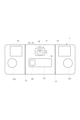
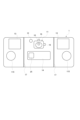
- FIG. 1 is a front view of the imaging device 1.
- FIG. FIG. 2 is a cross-sectional view of the right side of the imaging device 1.
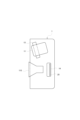
- FIG. 3 is a left side cross-sectional view showing the cooker 100 to which the imaging device 1 is temporarily fixed.
- the imaging device 1 has an imaging device 11, two lighting devices 13, and a control device .
- the control device 14 is provided inside the imaging device 1 .
- the controller 14 has a processor such as a CPU, for example.
- the control device 14 has, for example, a storage unit.
- the storage unit is, for example, semiconductor memory such as RAM (Random Access Memory) and ROM (Read Only Memory).
- the control device 14 adjusts the output of the illumination device 13 based on the light quantity F ⁇ b>1 transmitted from the light quantity detection sensor 12 so that the light quantity is suitable for imaging by the imaging device 11 . Specifically, when the amount of light F1 detected by the light amount detection sensor 12 is smaller than the threshold TH1, the control device 14 controls to increase the output of the lighting device 13 . On the other hand, when the light amount F1 detected by the light amount detection sensor 12 is equal to or greater than the threshold value TH1, control is performed to reduce the output of the lighting device 13 .
- the light amount detection sensor 12 detects the light amount F1 in the imaging direction 500 of the imaging device 11, and the control device 14 makes the output of the lighting device 13 suitable for imaging based on the light amount F1 detected by the light amount detection sensor 12.
- the control device 14 adjusts the output to be suitable for imaging, a good image can be easily captured.
- Two angle adjustment mechanisms 16 are provided to adjust the imaging angle of the imaging device 11 vertically and horizontally.
- a wireless communication device 25 provided in the control device 14 performs wireless communication with, for example, a smartphone.
- the wireless communication device 25 the user can view the video captured by the imaging device 11 of the imaging apparatus 1 using a smartphone or the like owned by the user.
- the light amount adjustment button 20 manually instructs to change the amount of light emitted from the lighting device 13 .
- the light amount adjustment button 20 further instructs the lighting device 13 to start and end lighting. Specifically, when the user presses the light amount adjustment button 20 when the illumination device 13 is not lit, the illumination device 13 projects a predetermined amount of light. After that, the control device 14 adjusts the output of the lighting device 13 so that the output is suitable for imaging. After the output of the lighting device 13 is adjusted by the control device 14, when the user presses the light amount increase button 201, the light amount emitted from the lighting device 13 increases. Further, when the user presses the light amount decrease button 202 after the control device 14 adjusts the output of the lighting device 13, the light amount emitted from the lighting device 13 decreases. When the light amount decrease button 202 is pressed after the light amount emitted from the lighting device 13 has decreased to a predetermined minimum light amount, the lighting device 13 is turned off.
- the control device 14 shown in FIGS. 1 and 2 has a function of stopping the output of the lighting device 13.
- the user takes an image of the cooking chamber 105 of the cooker 100 with the imaging device 1 , and after finishing the imaging, removes the imaging device 1 from the cooker 100 .
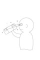
- the output of the lighting device 13 is stopped in order to prevent the user from directly looking at the light emitted from the lighting device 13 of the imaging device 1 (the high-output light that illuminated the cooking chamber 105).
- the light amount detection sensor 12 detects the surrounding light amount.
- the control device 14 acquires the ambient light intensity F ⁇ b>2 detected by the light intensity detection sensor 12 .
- the control device 14 compares the acquired light intensity F2 with the light intensity F1 stored in the storage unit. Specifically, the control device 14 calculates the difference between the light amount F2 and the light amount F1 as the change amount of the light amount. If the amount of change to the increasing side is equal to or greater than the threshold TH2, the control device 14 stops outputting the lighting device 13 .
- the threshold TH2 is an example of a first threshold.
- the control device 14 may adjust the output of the lighting device 13 to the lowest adjustable level instead of stopping the output of the lighting device 13. good.
- the user takes an image of the cooking chamber 105 of the cooker 100 with the imaging device 1 , and after finishing the imaging, removes the imaging device 1 from the cooker 100 .
- the output of the lighting device 13 is set to the lowest adjustable level. adjust the
- the control device 14 adjusts the output of the lighting device 13 so that the light quantity detected by the light quantity detection sensor 12 maintains a constant value. 6.
- FIG. 5 is a front view showing a state in which the imaging device 1 is attached and fixed to the observation window 102 of the cooker 100.
- FIG. 6 is a diagram showing a state in which the user has removed the imaging device 1 from the viewing window 102 of the cooker 100. As shown in FIG.
- the control device 14 adjusts the output of the lighting device 13 so that the light quantity detected by the light quantity detection sensor 12 maintains a constant value.
- the output of the illumination device 13 is increased so that the amount of light detected by the light amount detection sensor 12 is maintained at a constant value.
- the output of the lighting device 13 is reduced so that the amount of light detected by the light amount detection sensor 12 is maintained at a constant value.
- control device 14 detects when the amount of change to the increasing side, which is the difference between the two light amounts detected by the light amount detection sensor 12, is less than the threshold TH3, or when the amount of change to the decreasing side is less than the threshold TH3. does not adjust the output of the illumination device 13 .
- the threshold TH3 is an example of a second threshold. This assumes that the output of the illumination device 13 is not adjusted when the surrounding environment (light intensity) where the imaging device 1 is used changes only slightly. By doing so, it is possible to prevent frequent adjustment of the output of the lighting device 13 . As a result, it is possible to prevent flickering due to frequent adjustment of the light intensity of the illumination device 13 .
- the imaging of the cooking chamber 105 When the imaging of the cooking chamber 105 is finished and the user removes the imaging device 1 from the viewing window 102 of the cooking device 100 as shown in FIG. Since it is lowered, the output of the lighting device 13 that has illuminated the cooking chamber 105 is reduced. Therefore, it is possible to provide the user with the imaging device 1 that allows the output of the illumination device 13 to be easily adjusted. In addition, since the output of the lighting device 13 is small in a bright environment, it is possible to prevent the user from looking directly at the light 50 with a large output emitted from the lighting device 13, thereby preventing the user from hurting his/her eyes. can do.
- the control device 14 when the amount of change in the decreasing direction, which is the difference between the two amounts of light detected by the light amount detection sensor 12, when the output of the lighting device 13 is stopped, the control device 14 becomes equal to or greater than the threshold TH4.
- the illumination device 13 is caused to emit light.
- the threshold TH4 is an example of a third threshold. This assumes that the illumination device 13 is caused to emit light when the output of the illumination device 13 is stopped, for example, when the user attaches the imaging device 1 to the cooker 100 (when the environment is dark). are doing. By doing so, even when the output of the lighting device 13 is stopped, the cooking chamber 105 of the cooking device 100 can be illuminated when the imaging device 1 is attached to the cooking device 100 by the user. As a result, it is possible to provide the user with the imaging device 1 that allows the output of the illumination device 13 to be easily adjusted.
- control device 14 when the control device 14 has adjusted the output of the lighting device 13 but cannot reach the target light amount (a constant value or a value with a range), the control device 14 adjusts the output of the lighting device 13 within the adjustable range. Then, adjust the amount of light so that it approaches the target amount of light. [Embodiment 2]
- the light amount detection sensor 12 is provided, for example, in the vicinity of the imaging device 11 in front of the imaging device 1 as shown in FIG.
- the imaging device 1 preferably has an attachment detection device that detects whether the imaging device 1 is attached and fixed to the cooking appliance 100 .
- the attachment detection device can be configured by, for example, a proximity sensor provided in front of the imaging device 1 .
- the control device 14 controls to adjust the output of the lighting device 13 when the mounting is detected by the mounting detection device. More specifically, when the user uses the imaging device 1 detached from the cooker 100 , the user manually adjusts the output of the lighting device 13 . After that, when the imaging device 1 is attached to the cooker 100 (when the attachment is detected by the attachment detection device), the output of the lighting device 13 manually adjusted by the user has achieved its purpose, and therefore it is necessary to maintain the output. do not have. Therefore, when attachment is detected by the attachment detection device, even after the user manually adjusts the light amount of the illumination device 13, the control device 14 sets the output of the illumination device 13 as an output suitable for imaging. Adjust so that By doing so, a good image can always be obtained.
- the imaging device 1 is temporarily fixed to the cooker 100.
- attachment objects to which the imaging device 1 is temporarily fixed include aquariums, insect cages, trains, passenger cars, and airplanes.
- the imaging device 1 when the imaging device 1 is temporarily fixed to a water tank, the imaging device 1 may image the inside of the water tank from the outside through the transparent case of the water tank.
- the imaging device 1 When the imaging device 1 is temporarily fixed to the insect cage, the imaging device 1 may image the inside of the insect cage from the outside through the transparent case of the insect cage or the window of the insect cage.
- the imaging device 1 When the imaging device 1 is temporarily fixed to a train, a passenger car, or an airplane, the imaging device 1 images the outside from the inside of the train, the passenger car, or the airplane through the window of the train, the passenger car, or the airplane. good too.
- the imaging device 1 can perform imaging even when it is removed from the object to which it is attached. For example, it is possible to take an image of an object to be imaged, such as food, with the amount of light suitable for imaging with the imaging device 1 placed on a desk.
- the imaging device of the present invention is particularly useful for attaching to the viewing window of a cooker and imaging an object being cooked.
- Imaging device 11 imaging unit (imaging device) 12 sensor unit (light intensity detection sensor) 13 Lighting device 18 Power button 19 Recording button 20 Light amount adjustment button 21 Imaging range adjustment button 22 Lighting unit 23 Interface unit 24 Power supply terminal 25 Wireless communication device 60 Operation unit 100 Cooker 102 Peephole 105 Cooking room 115 Suction cup 400 Imaging range 500 Imaging Direction F1, F2 Light intensity TH1, TH2, TH3, TH4 Threshold
Landscapes
- Engineering & Computer Science (AREA)
- Multimedia (AREA)
- Signal Processing (AREA)
- Physics & Mathematics (AREA)
- General Physics & Mathematics (AREA)
- Human Computer Interaction (AREA)
- Chemical & Material Sciences (AREA)
- Combustion & Propulsion (AREA)
- Mechanical Engineering (AREA)
- General Engineering & Computer Science (AREA)
- Circuit Arrangement For Electric Light Sources In General (AREA)
Abstract
Description
図1は、撮像装置1の正面図である。図2は、撮像装置1の右側面の断面図である。図3は、撮像装置1が一時的に固定されている調理器100を示す左側断面図である。
[実施の形態2]
[他の実施の形態]
11 撮像部(撮像デバイス)
12 センサー部(光量検知センサー)
13 照明装置
18 電源ボタン
19 録画ボタン
20 光量調節ボタン
21 撮像範囲調節ボタン
22 点灯部
23 インターフェース部
24 電源端子
25 無線通信装置
60 操作部
100 調理器
102 のぞき窓
105 調理室
115 吸盤
400 撮像範囲
500 撮像方向
F1、F2 光量
TH1、TH2、TH3、TH4 閾値
Claims (7)
- 調理器ののぞき窓の外側に一時的に取り付けて前記調理器の調理室を撮像する装置であって、
撮像データを生成する撮像部と、
前記撮像部の撮像方向に投光する照明装置と、
前記撮像方向の光量を検知するセンサー部と、
前記センサー部によって検知された前記光量に基づいて、前記照明装置の出力を調節する制御装置とを有する、撮像装置。 - 前記撮像部は、前記センサー部として機能する、請求項1に記載の撮像装置。
- 前記制御装置は、前記光量が一定の値を維持するように前記照明装置の出力を調節する、請求項1又は請求項2に記載の撮像装置。
- 前記制御装置は、前記光量の増大側への変化量が第1閾値以上である場合に、前記照明装置の前記出力を停止するか、又は調節可能な最低レベルに前記出力を調節する、請求項1から請求項3のいずれか1項に記載の撮像装置。
- 前記制御装置は、前記光量の増大側への変化量が第2閾値未満である場合、又は、前記光量の減少側への変化量が前記第2閾値未満である場合は、前記照明装置の前記出力の調節を行わない、請求項1から請求項3のいずれか1項に記載の撮像装置。
- 前記制御装置は、前記照明装置の前記出力の停止状態において、前記光量の減少側への変化量が第3閾値以上になったときに、前記照明装置を投光させる、請求項1から請求項5のいずれか1項に記載の撮像装置。
- ユーザーの操作を受け付ける操作部を更に備え、
前記照明装置の出力の調節後又は前記照明装置の出力の停止後に、前記操作部が前記操作を受け付けると、前記制御装置は、前記操作に基づいて、前記出力を調節する、請求項1から請求項6のいずれか1項に記載の撮像装置。
Priority Applications (3)
| Application Number | Priority Date | Filing Date | Title |
|---|---|---|---|
| US18/709,789 US20250016457A1 (en) | 2021-11-19 | 2022-10-31 | Imaging apparatus |
| JP2023561511A JPWO2023090142A1 (ja) | 2021-11-19 | 2022-10-31 | |
| EP22895425.1A EP4435511A4 (en) | 2021-11-19 | 2022-10-31 | IMAGING DEVICE |
Applications Claiming Priority (2)
| Application Number | Priority Date | Filing Date | Title |
|---|---|---|---|
| JP2021-188639 | 2021-11-19 | ||
| JP2021188639 | 2021-11-19 |
Publications (1)
| Publication Number | Publication Date |
|---|---|
| WO2023090142A1 true WO2023090142A1 (ja) | 2023-05-25 |
Family
ID=86396798
Family Applications (1)
| Application Number | Title | Priority Date | Filing Date |
|---|---|---|---|
| PCT/JP2022/040790 Ceased WO2023090142A1 (ja) | 2021-11-19 | 2022-10-31 | 撮像装置 |
Country Status (5)
| Country | Link |
|---|---|
| US (1) | US20250016457A1 (ja) |
| EP (1) | EP4435511A4 (ja) |
| JP (1) | JPWO2023090142A1 (ja) |
| TW (1) | TW202321624A (ja) |
| WO (1) | WO2023090142A1 (ja) |
Citations (5)
| Publication number | Priority date | Publication date | Assignee | Title |
|---|---|---|---|---|
| JP2013223038A (ja) * | 2012-04-13 | 2013-10-28 | Olympus Imaging Corp | 撮像装置及び撮像のための照明方法 |
| JP2016080210A (ja) | 2014-10-10 | 2016-05-16 | パナソニックIpマネジメント株式会社 | 加熱調理器 |
| US20170134652A1 (en) * | 2015-11-06 | 2017-05-11 | L-3 Communications Corporation | Viewport for imaging in an rf/microwave environment |
| CN209593569U (zh) * | 2018-12-28 | 2019-11-05 | 上海达显智能科技有限公司 | 一种具有图像采集的智能设备 |
| WO2020170568A1 (ja) * | 2019-02-22 | 2020-08-27 | パナソニックIpマネジメント株式会社 | 加熱調理器 |
Family Cites Families (9)
| Publication number | Priority date | Publication date | Assignee | Title |
|---|---|---|---|---|
| US7646971B2 (en) * | 2006-11-07 | 2010-01-12 | Sony Ericsson Mobile Communications Ab | Assist light illuminance control |
| WO2009138359A2 (de) * | 2008-05-13 | 2009-11-19 | BSH Bosch und Siemens Hausgeräte GmbH | Haushaltsgerät mit bilderfassungsvorrichtung |
| DE102008055949B4 (de) * | 2008-11-05 | 2010-12-23 | Siemens Aktiengesellschaft | Optische Erfassungseinheit für Objekte |
| DE102011002187A1 (de) * | 2011-04-20 | 2012-10-25 | Miele & Cie. Kg | Haushaltsgerät |
| CA3199520A1 (en) * | 2014-06-05 | 2015-12-10 | Ingo Stork Genannt Wersborg | Heat treatment monitoring system |
| KR102362654B1 (ko) * | 2015-07-03 | 2022-02-15 | 삼성전자주식회사 | 오븐 |
| EP3321591B1 (en) * | 2016-11-15 | 2022-11-09 | Electrolux Appliances Aktiebolag | Monitoring device for household appliances and holding device |
| DE102017203305A1 (de) * | 2017-03-01 | 2018-09-06 | BSH Hausgeräte GmbH | Gargerät mit Sensorsystem |
| EP3879182A1 (en) * | 2020-03-10 | 2021-09-15 | Electrolux Appliances Aktiebolag | Camera module |
-
2022
- 2022-10-31 WO PCT/JP2022/040790 patent/WO2023090142A1/ja not_active Ceased
- 2022-10-31 US US18/709,789 patent/US20250016457A1/en active Pending
- 2022-10-31 JP JP2023561511A patent/JPWO2023090142A1/ja active Pending
- 2022-10-31 EP EP22895425.1A patent/EP4435511A4/en not_active Withdrawn
- 2022-11-17 TW TW111143941A patent/TW202321624A/zh unknown
Patent Citations (5)
| Publication number | Priority date | Publication date | Assignee | Title |
|---|---|---|---|---|
| JP2013223038A (ja) * | 2012-04-13 | 2013-10-28 | Olympus Imaging Corp | 撮像装置及び撮像のための照明方法 |
| JP2016080210A (ja) | 2014-10-10 | 2016-05-16 | パナソニックIpマネジメント株式会社 | 加熱調理器 |
| US20170134652A1 (en) * | 2015-11-06 | 2017-05-11 | L-3 Communications Corporation | Viewport for imaging in an rf/microwave environment |
| CN209593569U (zh) * | 2018-12-28 | 2019-11-05 | 上海达显智能科技有限公司 | 一种具有图像采集的智能设备 |
| WO2020170568A1 (ja) * | 2019-02-22 | 2020-08-27 | パナソニックIpマネジメント株式会社 | 加熱調理器 |
Non-Patent Citations (1)
| Title |
|---|
| See also references of EP4435511A4 |
Also Published As
| Publication number | Publication date |
|---|---|
| EP4435511A4 (en) | 2025-02-26 |
| US20250016457A1 (en) | 2025-01-09 |
| JPWO2023090142A1 (ja) | 2023-05-25 |
| TW202321624A (zh) | 2023-06-01 |
| EP4435511A1 (en) | 2024-09-25 |
Similar Documents
| Publication | Publication Date | Title |
|---|---|---|
| US9799232B2 (en) | Information processing apparatus and storage medium | |
| CN106874895A (zh) | 一种视线追踪装置及头戴式显示设备 | |
| JP6108150B2 (ja) | 照明制御システム | |
| JP6692799B2 (ja) | 照明の制御 | |
| US8496330B2 (en) | Ophthalmologic imaging apparatus and method for controlling the same | |
| EP3198992B1 (en) | Control of lighting | |
| US20160249805A1 (en) | Auxiliary flash assembly for a medical instrument | |
| JP2014017114A (ja) | 照明システム | |
| CN106575349A (zh) | 控制成像读取器的目标照明的系统及方法 | |
| CN102740761B (zh) | 电子内窥镜系统 | |
| CA3213560A1 (en) | Imaging apparatus | |
| CN110381806A (zh) | 电子内窥镜系统 | |
| WO2023090142A1 (ja) | 撮像装置 | |
| CN110169202B (zh) | 照明控制 | |
| EP3481261B1 (en) | An apparatus for providing semantic information and a method of operating the same | |
| KR101591084B1 (ko) | 카메라용 자동제어 led 플래쉬 | |
| JP2008235116A (ja) | 照明装置 | |
| TW201419936A (zh) | 智慧型動態調整發光參數之燈具 | |
| CN211409015U (zh) | 一种可自动调整灯板亮度的视力筛查仪 | |
| JP6939274B2 (ja) | 照明装置 | |
| WO2024168431A1 (en) | System and method for automatically controlling a dental instrument having integrated light sources | |
| JP2022102646A (ja) | 肌測定装置 | |
| JP2006352735A (ja) | 撮影装置及び撮影方法 |
Legal Events
| Date | Code | Title | Description |
|---|---|---|---|
| 121 | Ep: the epo has been informed by wipo that ep was designated in this application |
Ref document number: 22895425 Country of ref document: EP Kind code of ref document: A1 |
|
| ENP | Entry into the national phase |
Ref document number: 2023561511 Country of ref document: JP Kind code of ref document: A |
|
| WWE | Wipo information: entry into national phase |
Ref document number: 18709789 Country of ref document: US |
|
| WWE | Wipo information: entry into national phase |
Ref document number: 2022895425 Country of ref document: EP |
|
| NENP | Non-entry into the national phase |
Ref country code: DE |
|
| ENP | Entry into the national phase |
Ref document number: 2022895425 Country of ref document: EP Effective date: 20240619 |
|
| WWW | Wipo information: withdrawn in national office |
Ref document number: 2022895425 Country of ref document: EP |