WO2023090430A1 - セラミックスボール収納トレイおよびそれを用いたセラミックスボールの収納方法 - Google Patents
セラミックスボール収納トレイおよびそれを用いたセラミックスボールの収納方法 Download PDFInfo
- Publication number
- WO2023090430A1 WO2023090430A1 PCT/JP2022/042901 JP2022042901W WO2023090430A1 WO 2023090430 A1 WO2023090430 A1 WO 2023090430A1 JP 2022042901 W JP2022042901 W JP 2022042901W WO 2023090430 A1 WO2023090430 A1 WO 2023090430A1
- Authority
- WO
- WIPO (PCT)
- Prior art keywords
- ceramic
- ceramic ball
- diameter
- storage
- ball storage
- Prior art date
- Legal status (The legal status is an assumption and is not a legal conclusion. Google has not performed a legal analysis and makes no representation as to the accuracy of the status listed.)
- Ceased
Links
Images


Classifications
-
- B—PERFORMING OPERATIONS; TRANSPORTING
- B65—CONVEYING; PACKING; STORING; HANDLING THIN OR FILAMENTARY MATERIAL
- B65D—CONTAINERS FOR STORAGE OR TRANSPORT OF ARTICLES OR MATERIALS, e.g. BAGS, BARRELS, BOTTLES, BOXES, CANS, CARTONS, CRATES, DRUMS, JARS, TANKS, HOPPERS, FORWARDING CONTAINERS; ACCESSORIES, CLOSURES, OR FITTINGS THEREFOR; PACKAGING ELEMENTS; PACKAGES
- B65D1/00—Rigid or semi-rigid containers having bodies formed in one piece, e.g. by casting metallic material, by moulding plastics, by blowing vitreous material, by throwing ceramic material, by moulding pulped fibrous material or by deep-drawing operations performed on sheet material
- B65D1/34—Trays or like shallow containers
- B65D1/36—Trays or like shallow containers with moulded compartments or partitions
-
- B—PERFORMING OPERATIONS; TRANSPORTING
- B65—CONVEYING; PACKING; STORING; HANDLING THIN OR FILAMENTARY MATERIAL
- B65D—CONTAINERS FOR STORAGE OR TRANSPORT OF ARTICLES OR MATERIALS, e.g. BAGS, BARRELS, BOTTLES, BOXES, CANS, CARTONS, CRATES, DRUMS, JARS, TANKS, HOPPERS, FORWARDING CONTAINERS; ACCESSORIES, CLOSURES, OR FITTINGS THEREFOR; PACKAGING ELEMENTS; PACKAGES
- B65D71/00—Bundles of articles held together by packaging elements for convenience of storage or transport, e.g. portable segregating carrier for plural receptacles such as beer cans or pop bottles; Bales of material
- B65D71/70—Trays provided with projections or recesses in order to assemble multiple articles, e.g. intermediate elements for stacking
-
- B—PERFORMING OPERATIONS; TRANSPORTING
- B65—CONVEYING; PACKING; STORING; HANDLING THIN OR FILAMENTARY MATERIAL
- B65B—MACHINES, APPARATUS OR DEVICES FOR, OR METHODS OF, PACKAGING ARTICLES OR MATERIALS; UNPACKING
- B65B5/00—Packaging individual articles in containers or receptacles, e.g. bags, sacks, boxes, cartons, cans, jars
- B65B5/08—Packaging groups of articles, the articles being individually gripped or guided for transfer to the containers or receptacles
-
- B—PERFORMING OPERATIONS; TRANSPORTING
- B65—CONVEYING; PACKING; STORING; HANDLING THIN OR FILAMENTARY MATERIAL
- B65D—CONTAINERS FOR STORAGE OR TRANSPORT OF ARTICLES OR MATERIALS, e.g. BAGS, BARRELS, BOTTLES, BOXES, CANS, CARTONS, CRATES, DRUMS, JARS, TANKS, HOPPERS, FORWARDING CONTAINERS; ACCESSORIES, CLOSURES, OR FITTINGS THEREFOR; PACKAGING ELEMENTS; PACKAGES
- B65D85/00—Containers, packaging elements or packages, specially adapted for particular articles or materials
- B65D85/58—Containers, packaging elements or packages, specially adapted for particular articles or materials for ball bearings, washers, buttons or like spherical or disc-shaped articles
-
- F—MECHANICAL ENGINEERING; LIGHTING; HEATING; WEAPONS; BLASTING
- F16—ENGINEERING ELEMENTS AND UNITS; GENERAL MEASURES FOR PRODUCING AND MAINTAINING EFFECTIVE FUNCTIONING OF MACHINES OR INSTALLATIONS; THERMAL INSULATION IN GENERAL
- F16C—SHAFTS; FLEXIBLE SHAFTS; ELEMENTS OR CRANKSHAFT MECHANISMS; ROTARY BODIES OTHER THAN GEARING ELEMENTS; BEARINGS
- F16C41/00—Other accessories, e.g. devices integrated in the bearing not relating to the bearing function as such
- F16C41/04—Preventing damage to bearings during storage or transport thereof or when otherwise out of use
-
- C—CHEMISTRY; METALLURGY
- C04—CEMENTS; CONCRETE; ARTIFICIAL STONE; CERAMICS; REFRACTORIES
- C04B—LIME, MAGNESIA; SLAG; CEMENTS; COMPOSITIONS THEREOF, e.g. MORTARS, CONCRETE OR LIKE BUILDING MATERIALS; ARTIFICIAL STONE; CERAMICS; REFRACTORIES; TREATMENT OF NATURAL STONE
- C04B2235/00—Aspects relating to ceramic starting mixtures or sintered ceramic products
- C04B2235/70—Aspects relating to sintered or melt-casted ceramic products
- C04B2235/94—Products characterised by their shape
-
- C—CHEMISTRY; METALLURGY
- C04—CEMENTS; CONCRETE; ARTIFICIAL STONE; CERAMICS; REFRACTORIES
- C04B—LIME, MAGNESIA; SLAG; CEMENTS; COMPOSITIONS THEREOF, e.g. MORTARS, CONCRETE OR LIKE BUILDING MATERIALS; ARTIFICIAL STONE; CERAMICS; REFRACTORIES; TREATMENT OF NATURAL STONE
- C04B2235/00—Aspects relating to ceramic starting mixtures or sintered ceramic products
- C04B2235/70—Aspects relating to sintered or melt-casted ceramic products
- C04B2235/96—Properties of ceramic products, e.g. mechanical properties such as strength, toughness, wear resistance
-
- C—CHEMISTRY; METALLURGY
- C04—CEMENTS; CONCRETE; ARTIFICIAL STONE; CERAMICS; REFRACTORIES
- C04B—LIME, MAGNESIA; SLAG; CEMENTS; COMPOSITIONS THEREOF, e.g. MORTARS, CONCRETE OR LIKE BUILDING MATERIALS; ARTIFICIAL STONE; CERAMICS; REFRACTORIES; TREATMENT OF NATURAL STONE
- C04B35/00—Shaped ceramic products characterised by their composition; Ceramics compositions; Processing powders of inorganic compounds preparatory to the manufacturing of ceramic products
- C04B35/01—Shaped ceramic products characterised by their composition; Ceramics compositions; Processing powders of inorganic compounds preparatory to the manufacturing of ceramic products based on oxide ceramics
- C04B35/10—Shaped ceramic products characterised by their composition; Ceramics compositions; Processing powders of inorganic compounds preparatory to the manufacturing of ceramic products based on oxide ceramics based on aluminium oxide
-
- C—CHEMISTRY; METALLURGY
- C04—CEMENTS; CONCRETE; ARTIFICIAL STONE; CERAMICS; REFRACTORIES
- C04B—LIME, MAGNESIA; SLAG; CEMENTS; COMPOSITIONS THEREOF, e.g. MORTARS, CONCRETE OR LIKE BUILDING MATERIALS; ARTIFICIAL STONE; CERAMICS; REFRACTORIES; TREATMENT OF NATURAL STONE
- C04B35/00—Shaped ceramic products characterised by their composition; Ceramics compositions; Processing powders of inorganic compounds preparatory to the manufacturing of ceramic products
- C04B35/515—Shaped ceramic products characterised by their composition; Ceramics compositions; Processing powders of inorganic compounds preparatory to the manufacturing of ceramic products based on non-oxide ceramics
- C04B35/58—Shaped ceramic products characterised by their composition; Ceramics compositions; Processing powders of inorganic compounds preparatory to the manufacturing of ceramic products based on non-oxide ceramics based on borides, nitrides, i.e. nitrides, oxynitrides, carbonitrides or oxycarbonitrides or silicides
- C04B35/584—Shaped ceramic products characterised by their composition; Ceramics compositions; Processing powders of inorganic compounds preparatory to the manufacturing of ceramic products based on non-oxide ceramics based on borides, nitrides, i.e. nitrides, oxynitrides, carbonitrides or oxycarbonitrides or silicides based on silicon nitride
-
- F—MECHANICAL ENGINEERING; LIGHTING; HEATING; WEAPONS; BLASTING
- F16—ENGINEERING ELEMENTS AND UNITS; GENERAL MEASURES FOR PRODUCING AND MAINTAINING EFFECTIVE FUNCTIONING OF MACHINES OR INSTALLATIONS; THERMAL INSULATION IN GENERAL
- F16C—SHAFTS; FLEXIBLE SHAFTS; ELEMENTS OR CRANKSHAFT MECHANISMS; ROTARY BODIES OTHER THAN GEARING ELEMENTS; BEARINGS
- F16C43/00—Assembling bearings
- F16C43/04—Assembling rolling-contact bearings
Definitions
- the embodiments described later relate to a ceramic ball storage tray and a ceramic ball storage method using the same.
- Ceramic balls are used in fields such as bearings.
- Various materials such as silicon nitride, aluminum oxide, and zirconium oxide are used as ceramics.
- Patent Document 1 discloses a bearing ball made of a silicon nitride sintered body.
- the ceramic ball of Patent Document 1 has excellent wear resistance even if it is as large as 20 mm in diameter.
- the bearing has a structure in which multiple bearing balls are installed between the outer ring and the inner ring. In other words, a plurality of bearing balls are required to manufacture one bearing. Along with this, it has become necessary to transport a plurality of ceramic balls.
- Patent Document 2 discloses a paper container for containing bearing balls.
- Patent Literature 2 discloses a container using cardboard in which at least two corrugated cardboard liners are laminated and interleaved. The paper container of Patent Document 2 shows that even if a plurality of bearing balls are accommodated, the container will not be damaged.
- Patent Document 3 discloses a ceramic ball having a belt-like portion. When a plurality of ceramic balls having band-shaped portions were put into one container, many cracks and chips were generated. This is because the banding portions are likely to be damaged when they collide with each other.
- the problem to be solved by the ceramic ball storage tray and the ceramic ball storage method using the same according to the embodiment is to reduce the breakage of the ceramic balls stored in the ceramic ball storage tray in order to deal with such problems. It is to be.
- the ceramic ball storage tray according to the embodiment has a storage section for storing ceramic balls.
- the storage portion of the ceramic ball storage tray has a convex portion in which the center of the bottom surface of the storage portion is hollow. Also, the height of the outer peripheral surface of the projection with respect to the diameter of the ceramic ball is within the range of 0.05 or more and 0.30 or less.
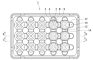
- FIG. 1 is a top view showing an example of a ceramic ball storage tray according to an embodiment
- FIG. (A) is a side view showing an example of the ceramic ball storage tray according to the embodiment
- (B) is a BB cross-sectional view showing an example of the ceramic ball storage tray according to the embodiment
- (C) is the ceramic according to the embodiment.
- FIG. 2 is an enlarged view showing the BB cross section of the storage portion of the ceramic ball storage tray according to the embodiment
- FIG. 4 is an enlarged view showing the BB cross section of the storage unit in which the ceramic ball storage trays according to the embodiment are vertically stacked.
- the ceramic ball storage tray according to the embodiment has a storage section for storing ceramic balls.
- the storage portion of the ceramic ball storage tray has a convex portion in which the center of the bottom surface of the storage portion is hollow. Also, the height of the outer peripheral surface of the projection with respect to the diameter of the ceramic ball is within the range of 0.05 or more and 0.30 or less.
- FIG. 1 is a top view showing an example of the ceramic ball storage tray according to the embodiment.
- FIG. 2A is a side view showing an example of the ceramic ball storage tray according to the embodiment.
- FIG. 2B is a BB cross-sectional view showing an example of the ceramic ball storage tray according to the embodiment.
- FIG. 2(C) is a CC sectional view showing an example of the ceramic ball storage tray according to the embodiment.
- FIG. 3 is an enlarged view showing the BB cross section of the storage portion of the ceramic ball storage tray according to the embodiment.
- FIG. 4 is an enlarged view showing the BB cross section of the storage portion in which the ceramic ball storage trays according to the embodiment are vertically stacked.
- reference numeral 1 is a ceramic ball storage tray
- reference numeral 2 is a storage portion
- reference numeral 3 is ceramic balls
- reference numeral 4 is a convex portion
- reference numeral 5 is the height of the outer peripheral surface of the convex portion 4
- reference numeral 6 is the inside of the convex portion 4.
- FIG. 7 is the diameter of the ceramic ball 3; 8 is the height of the storage portion 2; 9 is the diameter of the outer peripheral surface of the convex portion 4; 10 is the diameter of the inner peripheral surface of the convex portion 4; Reference numeral 11 denotes a bottom portion, reference numeral 12 denotes a peripheral portion of the storage portion 2, reference numeral 13 denotes a diameter of the storage portion 2, and reference numeral 14 denotes a recess of the peripheral portion 12.
- FIG. FIG. 1 illustrates that the ceramic ball storage tray 1 has 15 storage portions 2 .
- the tray 1 is not limited to this, and the number of storage units 2 can be increased or decreased.
- FIG. 1 illustrates that the ceramic ball storage tray 1 has 15 storage portions 2 .
- the tray 1 is not limited to this, and the number of storage units 2 can be increased or decreased.
- FIG. 1 illustrates that the ceramic ball storage tray 1 has 15 storage portions 2 .
- the tray 1 is not limited to this, and the number of storage units 2 can be increased or decreased.
- the ceramic ball storage tray 1 is exemplified by arranging 3 storage units in the vertical direction and 5 storage units in the horizontal direction, but the number of storage units can also be increased or decreased as appropriate.
- the ceramic ball storage tray 1 may also be called storage tray 1 or tray 1 .
- the ceramic balls 3 are sometimes simply called balls 3 .
- FIG. 1 two rows of storage portions 2 on the right side show a state in which ceramic balls 3 are stored therein.
- the storage tray 1 has a storage section 2.
- the storage part 2 can store the ceramic balls 3 .
- the storage portion 2 has a convex portion 4 in which the center C of the bottom portion 11 is hollow.
- a bottom portion 11 of the storage portion 2 is designed so that the ceramic balls 3 do not fall off.
- the opposite side of the bottom portion 11 that is, the ceiling side
- the convex portion 4 of the bottom portion 11 of the storage portion 2 has a shape that protrudes downward from the bottom portion 11 .
- the presence of the projections 4 makes it possible to absorb the impact during transportation of the tray 1 (that is, during transportation of the ceramic balls 3). Further, as will be described later, by having the projections 4 in the storage portion 2, when the storage trays 1 are vertically stacked, it is possible to prevent the vertically adjacent ceramic balls 3 from coming into direct contact with each other.
- the convex portion 4 has a hollow cylindrical shape in which the center C of the bottom portion 11 is hollow. Since the projection 4 is a hollow cylinder, the strength of the projection 4 can be improved.
- the convex portion 4 is a hollow cylinder that is circular when viewed from above will be described below, but the present invention is not limited to this case.
- the convex portion 4 may have a polygonal shape when viewed from above.
- the diameter 7 of the ceramic ball 3 is called a ball diameter 7 .
- the ceramic ball 3 may be a ceramic ball having a belt-like portion. When the ceramic ball is manufactured using mold molding, it becomes a ceramic ball having a band-shaped portion. A spherical ceramic ball is obtained by polishing a ceramic ball having a band-shaped portion.
- the storage tray 1 may store either spherical ceramic balls or ceramic balls provided with band-shaped portions. In other words, the ceramic ball 3 includes both a spherical shape and a shape having a band-like portion. Also, the ceramic ball before polishing is sometimes called a bare ball.
- a ball diameter 7 is the maximum diameter of the ceramic ball 3 . If the ceramic ball 3 is truly spherical, the maximum diameter will be any diameter. When the ceramic ball 3 has a belt-like portion, the diagonal line of the belt-like portion is the maximum diameter.
- the convex portion 4 is a hollow convex shape, it has an outer peripheral surface 41 and an inner peripheral surface 42 that rise in the height direction. Assume that the height of the outer peripheral surface 41 is 5, and the height of the inner peripheral surface 42 is 6. The height 5 of the outer peripheral surface 41 of the convex portion 4 is sometimes referred to as the outer peripheral height 5 . The height 6 of the inner peripheral surface 42 of the convex portion 4 is sometimes called the inner peripheral height 6 .
- the height 6 of the inner peripheral surface 42 is preferably lower than the height 5 of the outer peripheral surface 41 so that the ceramic balls 3 to be accommodated are held on the ceiling side of the inner peripheral surface 42 .
- the height 6 of the outer peripheral surface 41 of the convex portion 4 with respect to the ball diameter 7, that is, "peripheral height of convex portion 5/ball diameter 7" is within the range of 0.05 or more and 0.30 or less. be.
- the vertically adjacent ceramic balls 3 are in direct contact with each other when a plurality of storage trays 1 are vertically stacked. you can avoid it.
- peripheral height 5/ball diameter 7 is less than 0.05, the effect of providing the convex portion 4 cannot be obtained. Further, if the ratio of "peripheral height 5/ball diameter 7" exceeds 0.30, the projection 4 becomes too high. If the convex portion 4 is high, there is a possibility that the stability when the trays 1 are stacked one on top of the other is lowered. Therefore, it is preferable that the ratio of "peripheral height 5/ball diameter 7" is in the range of 0.05 or more and 0.30 or less, more preferably 0.10 or more and 0.25 or less.
- the height 6 of the inner peripheral surface 42 of the convex portion 4 with respect to the diameter 7 of the ceramic ball 3, ie, "the inner peripheral height of the convex portion 6/the ball diameter 7" is within the range of 0.01 or more and 0.10 or less. Preferably. Moreover, it is desirable that the height 6 of the inner peripheral surface 42 is lower than the height 5 of the outer peripheral surface 41 .
- the inner peripheral height 6 of the convex portion 4 is the height of the inner peripheral side of the hollow convex portion 4 .
- the ratio of "inner peripheral height of convex portion 6/ball diameter 7" is set to within the range of 0.01 or more and 0.10 or less, when a plurality of trays 1 are vertically stacked, the inner peripheral side of the convex portion 4
- the ceramic balls 3 stored in the lower tray 1 can be suppressed. Even if a plurality of trays 1 are stacked and transported, movement of the stored ceramic balls 3 can be suppressed. Therefore, it is possible to prevent the ceramic balls 3 from being damaged when the tray 1 is transported.
- the inner circumference height 6 of the convex portion/the ball diameter 7 is less than 0.01, the inner circumference height 6 of the convex portion 4 is small.
- the bottom portion 11 of the storage portion 2 of the upper tray 1 will come into direct contact with the ceramic balls 3 of the lower tray 1 .
- the stress applied to the ceramic balls 3 increases and the possibility of breakage increases.
- the ratio of "inner peripheral height of convex portion 6/ball diameter 7" exceeds 0.10, the convex portion 4 may be too high.
- the ratio of the height of the storage portion 2 to the diameter 7 of the ceramic ball 3, ie, "the height of the storage portion 8/the diameter of the ball 7" is within the range of 1.05 or more and 2.00 or less.
- the height 8 of the storage portion 2 is the length from the bottom surface portion 11 of the storage portion 2 to the opening on the opposite side. First, a vertical line is drawn vertically from the center of the bottom surface portion 11 of the storage portion 2 . Next, a horizontal line (perpendicular to the vertical line) is drawn so as to connect the opening of the storage unit 2 from end to end. A height 8 of the storage section 2 is defined as a length from the center of the bottom surface portion 11 of the storage section 2 to the intersection of the vertical line and the horizontal line.
- the height of the storage portion 8/the ball diameter 7 within the range of 1.05 to 2.00, it is possible to prevent the ceramic balls 3 from moving too much when the tray 1 is transported. Therefore, it is possible to prevent the ceramic balls 3 from being damaged when the tray 1 is transported. Moreover, even the ceramic ball 3 having a band-like portion can be prevented from being damaged.
- the ratio of "height of storage portion 8/ball diameter 7" is in the range of 1.05 to 2.00, more preferably in the range of 1.08 to 1.60.
- diameter 13 of the storage portion 2 to the diameter 7 of the ceramic ball 3, ie, "diameter 13 of the storage portion/ball diameter 7" is within a range of 1.05 or more and 1.70 or less. If the ratio of "diameter of storage portion 13/ball diameter 7" is less than 1.05, it may be difficult for the ball 3 to enter during storage. Also, if the "diameter of storage portion/ball diameter" exceeds 1.70, there is a possibility that the balls 3 will move too much when the tray 1 is transported.
- FIG. 1 An example of stacking storage trays 1 is shown in FIG.
- the structure is such that when a plurality of storage trays 1 are stacked vertically, the balls stored in the lower tray 1 are held down by the projections 4 of the upper tray 1. ⁇ Thereby, movement of the balls 3 can be suppressed when the tray 1 is conveyed.
- the outer peripheral height 5 of the convex portion 4 is greater than the inner peripheral height 6 of the convex portion 4 .
- the fact that the outer peripheral height 5 of the protrusion 4 is greater than the inner peripheral height 6 of the protrusion indicates that the bottom surface portion 11 of the storage portion 2 has a step. Thereby, one ceramics ball 3 can be supported at a plurality of locations. As a result, movement of the ceramic balls 3 during transportation of the tray 1 can be suppressed.
- the outer peripheral height 5 of the projection 4 is 3 mm or more. By setting the outer peripheral height 5 of the protrusion 4 to 3 mm or more, it becomes easy to form a step on the bottom surface portion 11 of the storage portion 2 .
- the projections 4 play a role of preventing misalignment.
- the inner peripheral surface of the storage portion 2 can take various shapes such as a spherical shape and a stepped shape.
- the inner peripheral surface of the storage portion 2 may be spherical, and the convex portion 4 may be hollow. The hollow part becomes a step.
- the projections 4 hollow it is possible to enhance the cushioning property to the ceramic balls 3 when a plurality of trays 1 are vertically stacked. Also, the weight of the tray 1 can be reduced.
- the diameter 9 of the outer peripheral surface 41 of the protrusion 4 with respect to the diameter 7 of the ceramic ball 3 is within the range of 0.3 or more and 0.8 or less.
- the diameter 10 of the inner peripheral surface 42 of the convex portion 4 with respect to the diameter 7 of the ceramic ball 3, ie, "the inner peripheral diameter of the convex portion 10/the ball diameter 7" is within the range of 0.1 or more and 0.6 or less. is preferred. It goes without saying that the inner diameter 10 is smaller than the outer diameter 9 .
- the outer diameter 9 of the convex portion 4 is the outer diameter based on the tip portion (that is, the lower end portion) of the convex portion 4 .
- the inner circumference diameter 10 of the convex portion 4 is the inner diameter based on the tip portion (that is, the lower end portion) of the convex portion.
- the ratio of "peripheral diameter 9 of convex portion/ball diameter 7" is less than 0.3, the outer peripheral diameter 9 of convex portion 4 may become too small. If the outer diameter 9 of the protrusion 4 is small, the difference between the outer diameter 9 and the inner diameter 10 may become small. As the difference between the outer diameter 9 and the inner diameter 10 becomes smaller, the area of the projections 4 contacting the ceramic balls 3 stored in the lower tray 1 becomes smaller when the trays 1 are vertically stacked. Vibration during transportation of the tray 1 sharply contacts the protrusions 4 with the ceramic balls 3, which may cause damage. Further, if the ratio of "peripheral diameter of convex portion 9/ball diameter 7" exceeds 0.8, the outer diameter of convex portion 4 may become too large.
- the inner circumference diameter of the convex portion 10/the ball diameter 7 when “the inner circumference diameter of the convex portion 10/the ball diameter 7" is within the range of 0.1 or more and 0.6 or less, the plurality of trays 1 are stored in the lower tray 1 when stacked vertically. The effect of suppressing the ceramic balls 3 can be further obtained. Also, if the ratio of "inner peripheral diameter of convex portion 10/ball diameter 7" is less than 0.1, inner peripheral diameter 10 may become too small. Further, if the ratio of "inner peripheral diameter of convex portion 10/ball diameter 7" exceeds 0.6, the width of the convex portion 4 may become too narrow. If the width of the protrusions 4 is too narrow, when the plurality of trays 1 are stacked vertically, the protrusions 4 sharply hit the ceramic balls 3 stored in the lower tray 1, causing damage. there is a possibility.
- both the ratio of "peripheral diameter of convex portion 9/ball diameter 7" of 0.3 to 0.8 and the ratio of "internal diameter of convex portion 10/ball diameter 7" of 0.1 to 0.6 are required. preferably fulfilled.
- a peripheral portion 12 is provided around the storage portion 2 .
- the peripheral portion 12 connects adjacent storage portions 2 .
- the peripheral portion 12 may be a housing that covers the side surface of the storage portion 2 .
- the surrounding portions 12 may be provided further outside the storage portions 2 at the ends of the plurality of storage portions 2 (for example, the upper end, the lower bridge, and the right end in FIG. 1).
- the storage tray 1 is preferably made of plastic.
- Plastic is also called synthetic resin.
- a plastic is a plastic material whose main raw material is a polymer material derived from petroleum or the like. Plastics can be molded by applying heat and pressure. Since plastic can be molded, it is suitable for forming the housing portion 2 as described above.
- Materials for the tray 1 include plastic, rubber, paper, glass, and ceramics. Of these, plastic is suitable from the viewpoint of strength and weight reduction. Plastics include polyethylene terephthalate (PET), polypropylene (PP), polyethylene (PE), and the like. Among these, polyethylene terephthalate is preferred. This is because polyethylene terephthalate has good recyclability.
- the diameter 7 of the ceramic balls 3 stored in the storage tray 1 is 10 mm or more. That is, the storage portion 2 has a size and shape that can store the ceramic balls 3 having a diameter of 10 mm or more. As the diameter of the ceramic balls 3 increases, the area of contact with the storage tray 1 due to vibration during transportation also increases. Further, as the diameter of the ceramic ball 3 increases, the weight also increases. As the weight increases, so does the stress it encounters due to vibration. By using the storage tray 1 according to the embodiment, the influence of vibration during transportation can be suppressed. In other words, it can be said that the storage tray 1 is a tray effective for storing the ceramic balls 3 having a diameter of 10 mm or more. Although the upper limit of the diameter of the ceramic ball 3 is not particularly limited, it is preferably 100 mm or less. Moreover, the storage tray 1 according to the embodiment may also be applied to the ceramic balls 3 having a diameter of less than 10 mm.
- the ceramic balls 3 may be one or more selected from silicon nitride sintered bodies, sialon sintered bodies, aluminum oxide sintered bodies, zirconium oxide sintered bodies, and algyl sintered bodies.
- An algyl sintered body is a sintered body obtained by mixing aluminum oxide and zirconium oxide.
- the silicon nitride sintered body includes a sintered body containing 85% by mass or more of silicon nitride.
- the ceramic ball 3 is preferably a silicon nitride sintered body.
- a silicon nitride sintered body is more expensive than an aluminum oxide sintered body. If the ceramic balls 3 are damaged during transportation of the tray 1, the economic loss is large. Therefore, it is preferable to apply the storage tray 1 of the embodiment to the ceramic balls 3 made of a silicon nitride sintered body.
- silicon nitride sintered bodies, sialon sintered bodies, zirconium oxide sintered bodies, and algyl sintered bodies have a three-point bending strength of 800 MPa or more.
- the aluminum oxide sintered body has a three-point bending strength of about 300 to 500 MPa. Even if the ceramic balls 3 stored in the storage tray 1 of the embodiment are low-strength aluminum oxide ceramic balls, breakage can be suppressed.
- the storage tray 1 as described above is used for storing the ceramic balls 3, and the ceramic balls 3 are stored in the storage process.
- the storing step includes a step of inserting a finger or a robot arm holding the ceramic balls 3 from the opening of the storage tray 1 toward the storage portion 2, and setting and storing the balls 3 in the storage portion 2. and a step of vertically stacking a plurality of storage trays 1 in which ceramic balls 3 are stored.
- a plurality of storage trays 1 are transported in a state of being vertically stacked. Due to the configuration of the storage tray 1, it is possible to suppress damage to the ceramic balls 3 due to vibration during transportation of the storage tray 1.
- the storage tray 1 when the storage tray 1 is provided with a plurality of storage portions 2 , the storage tray 1 does not have to store the ceramic balls 3 in all the storage portions 2 .
- the ceramic ball 3 having a belt-like portion is polished to become a true spherical ceramic ball 3 .
- the spherical ceramic balls 3 can be used as bearing balls.
- a plurality of bearing balls are used to assemble the bearing. In completing the bearing, a process of transporting the tray 1 occurs. It is important to prevent damage to the ceramic balls 3 during transportation of the tray 1 .
- a plurality of storage trays 1 storing balls 3 may be vertically stacked.
- the vertically adjacent ceramic balls 3 can be prevented from coming into contact with each other.
- vertically adjacent ceramic balls 3 may be in contact with each other via convex portions 4 . If a plurality of storage trays 1 can be piled up, the work of transporting the trays 1 can be carried out efficiently. Further, by providing the convex portion 4 as described above, it is possible to adopt a structure in which the upper and lower trays 1 are fitted. When a plurality of trays 1 are stacked and transported, it is possible to prevent the upper and lower trays 1 from being misaligned.
- the storage tray 1 as described above can prevent the ceramic balls 3 from being damaged due to vibration or dropping. Performance evaluation of the storage tray 1 can be performed by a vibration test and a drop test according to JIS-Z-0200 (2013). JIS-Z-0200 corresponds to ISO4180.
- level 1 of the JIS-Z-0200 vibration test and level 1 of the drop test 1 are performed, breakage of the ceramic balls 3 can be suppressed.
- the vibration test has levels, and level 1 is the most severe condition.
- the drop test has levels, and level 1 is the most severe condition.
- the storage tray 1 has no damage to the tray itself even when subjected to level 1 vibration test and level 1 drop test. Further, even if the level 1 vibration test is performed on the tray 1 containing the ceramic balls 3, the breakage of the ceramic balls 3 can be reduced to 0% or more and 1% or less. Similarly, even if the level 1 drop test is performed using the tray 1 containing the ceramic balls 3, the breakage of the ceramic balls 3 can be reduced to 0% or more and 1% or less. Therefore, it is possible to prevent the ceramic balls 3 from being damaged during transportation.
- Example 1 (Examples 1 to 10, Comparative Examples 1 to 4)
- Storage trays 1 according to Examples 1 to 10 and storage trays according to Comparative Examples 1 to 4 were made of plastic and had a width of 523 mm and a length of 415 mm.
- a storage portion 2 is provided in the storage tray 1 according to Examples 1 to 10.
- FIG. On the other hand, the storage trays according to Comparative Examples 1 and 4 were not provided with the storage portion 2 , and the storage trays according to Comparative Examples 2 and 3 were provided with storage portions outside the range of the storage portion 2 .
- Table 1 shows the shapes of the ceramic balls to be stored and the shape of the storage portion.
- the ceramic balls stored in the storage trays according to Examples 1 to 8 and Comparative Examples 1 to 3 were made of silicon nitride sintered bodies. Further, the ceramic balls stored in the storage trays according to Examples 9 to 10 and Comparative Example 4 were made of sintered aluminum oxide.
- the silicon nitride sintered ceramic balls used had a three-point bending strength of 950 MPa. Also, the aluminum oxide ceramic balls used had a three-point bending strength of 400 MPa.
- Comparative Examples 1 and 4 a square-shaped container with a width of 523 mm and a length of 415 mm was used. For this reason, Comparative Example 1 does not have a storage portion. Moreover, Comparative Example 2 was the same as Example 1 except that no convex portion was provided. In Comparative Example 3, the outer peripheral height/ball diameter was 0.5.
- the outer circumference height of the convex part/ball diameter, the inner circumference height of the convex part/ball diameter, the outer circumference diameter of the convex part/ball diameter, and the inner circumference diameter of the convex part/ball diameter , the height of the container/ball diameter, and the number of the containers in one container tray are shown in Table 2.
- Ceramic balls were stored in all the storage portions of the storage trays according to Examples and Comparative Examples. Also, in Comparative Examples 1 and 4, 20 ceramic balls were stored in one storage portion.
- a vibration test and a drop test were performed on each of the storage trays according to the example and the comparative example. The test was carried out by vertically stacking storage trays storing ceramic balls in three stages. A sample was prepared by packing storage trays stacked in three stages with corrugated cardboard and fixing them with binding bands. The binding band was fixed at two locations in the vertical direction and at two locations in the horizontal direction.
- the vibration test was conducted according to level 1 of random vibration test of JIS-Z-0200 (2013).
- the vibration frequency was 6 Hz
- the vibration direction was vertical
- the vibration was performed for 180 minutes.
- the drop test was conducted in accordance with JIS-Z-0200 (2013) Level 1.
- the drop height was 60 cm.
- the falling order is 2-3-5 corners, 3-5 corners, 2-3 corners, 2-5 corners, 2-3-6 corners, 3-6 corners, 2-6 corners, 5 sides, 6 sides , 2nd, 3rd, and 1st.
- the test was conducted by preparing 10 samples for each.
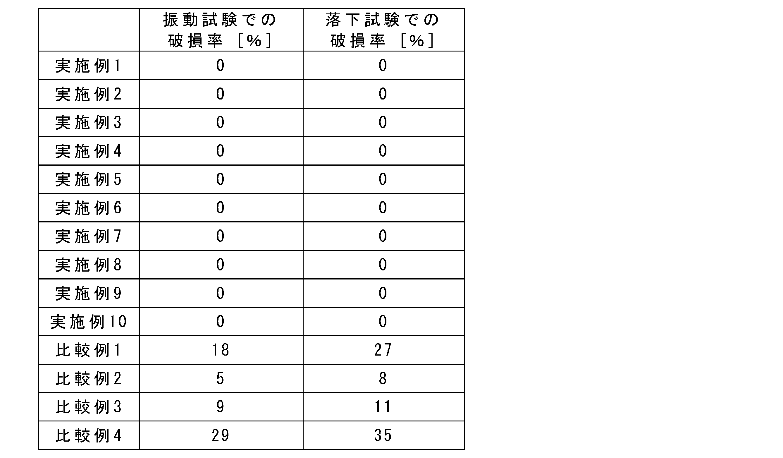
- the proportion of ceramic balls damaged in the vibration test and drop test was determined as the damage rate (%).
- a square box without a storage section, such as Comparative Examples 1 and 4 had a high breakage rate.
- the breakage rate increased significantly.
- Comparative Example 2 in which there is no convex portion in the storage portion, the breakage rate was high because the ball was not sufficiently restrained by the convex portion when the trays were stacked one on top of the other.
- Comparative Example 3 when the trays were stacked one on top of the other, the stress on the balls accommodated in the lower tray increased, resulting in an increased breakage rate.
Landscapes
- Engineering & Computer Science (AREA)
- Mechanical Engineering (AREA)
- General Engineering & Computer Science (AREA)
- Ceramic Engineering (AREA)
- Packaging Of Annular Or Rod-Shaped Articles, Wearing Apparel, Cassettes, Or The Like (AREA)
- Packaging Frangible Articles (AREA)
Abstract
Description
例えば、特開2004-18050号公報(特許文献2)には、ベアリングボールを収納する紙製容器が開示されている。特許文献2では、段ボール用ライナを少なくとも二枚以上積層合紙した厚紙を用いた容器である。特許文献2の紙製容器は、ベアリングボールを複数個収納したとしても、容器が破損しないことを示している。
また、ボール直径7はセラミックスボール3の最大径である。セラミックスボール3が真球状であれば、最大径は任意の直径となる。セラミックスボール3が帯状部を具備する場合は、帯状部の対角線が最大径となる。
また、凸部4は中空の凸状であるため、高さ方向にせり立つ外周面41および内周面42を有している。外周面41の高さを5、内周面42の高さを6とする。凸部4の外周面41の高さ5のことを、外周高さ5と呼ぶこともある。凸部4の内周面42の高さ6を、内周高さ6と呼ぶこともある。収容されるセラミックスボール3を内周面42の天井側で保持するようにするため、内周面42の高さ6は、外周面41の高さ5より低いことが望ましい。
また、セラミックスボール3の直径7に対する収納部2の高さである「収納部の高さ8/ボール直径7」が1.05以上2.00以下の範囲内であることが好ましい。収納部2の高さ8とは、収納部2の底面部11から、反対側の開口部までの長さである。
まず、収納部2の底面部11の中心から上下に鉛直線を引く。次に、収納部2の開口部を端から端につながるように水平線(鉛直線の直交線)を引く。収納部2の底面部11の中心から、前記垂直線と前記水平線が交点までの長さを収納部2の高さ8とする。
また、セラミックスボール3の直径7に対する収納部2の直径13である「収納部の直径13/ボール直径7」は1.05以上1.70以下の範囲内であることが好ましい。「収納部の直径13/ボール直径7」が1.05未満であると、収納時にボール3が入り難くなる可能性がある。また、「収納部の直径/ボール直径」が1.70を超えると、トレイ1の搬送時にボール3が動き過ぎる可能性がある。
セラミックスボール3の直径7に対する凸部4の外周面41の直径9である「凸部の外周直径9/ボール直径7」が0.3以上0.8以下の範囲内であることが好ましい。また、セラミックスボール3の直径7に対する凸部4の内周面42の直径10である「凸部の内周直径10/ボール直径7」が0.1以上0.6以下の範囲内であることが好ましい。なお、内周直径10が外周直径9より小さいことは言うまでもない。凸部4の外周直径9は凸部4の先端部(すなわち、下端部)を基準とする外径とする。また、凸部4の内周直径10は凸部の先端部(すなわち、下端部)を基準とする内径とする。
また、「凸部の外周直径9/ボール直径7」が0.8を超えると、凸部4の外径が大きくなる過ぎる可能性がある。凸部4の外径が大きくしたとしても、それ以上の効果が得られない。また、「凸部の外周直径9/ボール直径7」が0.8以下であると収納トレイ1を軽量化する効果がある。
また、「凸部の内周直径10/ボール直径7」が0.1未満であると、内周直径10が小さくなり過ぎる可能性がある。また、「凸部の内周直径10/ボール直径7」が0.6を超えると、凸部4の幅が狭くなり過ぎる可能性がある。凸部4の幅が狭くなり過ぎると、複数のトレイ1を上下に重ねたときに下側のトレイ1に収納したセラミックスボール3への凸部4の当たり方が鋭くなり、破損の原因となる可能性がある。
収納部2の周囲には周囲部12がある。この周囲部12は隣り合う収納部2同士をつないでいる。周囲部12は収納部2の側面を覆うような筐体であってもよい。なお、複数の収納部2のうち端(例えば、図1では上端、下橋および右端)の収納部2のさらに外側にも周囲部12を設けてもよい。また、収納部2の周囲の周囲部12にトレイ1の開口部側から底面部11側に向かってくぼみ14を設けることが好ましい。くぼみ14を介してボール3を保持した指またはロボットアームをトレイ1の開口部から収納部2に向かって挿入し易くなるため、収納部2にボール3をセットし易くすることができる。また、くぼみ14を介して指またはロボットアームで収納部2に収納されたボール3を掴みやすくなるので、収納部2に収納されたボール3をトレイ1から取り出し易くすることができる。
収納トレイ1はプラスチックからなることが好ましい。プラスチックは合成樹脂とも呼ばれている。プラスチックは、石油などに由来する高分子材料を主原料とした可塑性を有する物質のことである。プラスチックは、熱や圧力を加えることにより成形加工を行うことができる。プラスチックは成形加工が可能なため、前述のような収納部2を形成するのに適している。トレイ1の材質としては、プラスチック、ゴム、紙、ガラス、セラミックスなどが挙げられる。この中ではプラスチックが強度と軽量化の観点から適している。また、プラスチックとしては、ポリエチレンテレフタレート(PET)、ポリプロピレン(PP)、ポリエチレン(PE)などが挙げられる。この中では、ポリエチレンテレフタレートが好ましい。ポリエチレンテレフタレートはリサイクル性が良いためである。
収納トレイ1に収納されるセラミックスボール3の直径7は10mm以上であることが好ましい。つまり、収納部2は、直径が10mm以上であるセラミックスボール3を収納可能なサイズ及び形状を備える。セラミックスボール3は直径が大きくなると、収納トレイ1の搬送時の振動で接触する面積も大きくなる。また、セラミックスボール3の直径が大きくなると重量も増えていく。重量が増えると、振動でぶつかる応力も増える。実施形態にかかる収納トレイ1を用いることにより、搬送時の振動の影響を抑制できる。言い換えると、収納トレイ1は、直径10mm以上のセラミックスボール3を収納することに効果的なトレイであると言える。なお、セラミックスボール3の直径の上限は特に限定されるものではないが、100mm以下が好ましい。また、実施形態にかかる収納トレイ1は直径が10mm未満のセラミックスボール3にも適用してもよいものである。
セラミックスボール3の収納方法は、以上のような収納トレイ1を用い、収納工程において、セラミックスボール3を収納する。具体的には、収納工程は、セラミックスボール3を保持した指またはロボットアームを収納トレイ1の開口部から収納部2に向かって挿入し、収納部2にボール3をセットして収納する工程と、セラミックスボール3が収納された複数の収納トレイ1を上下に重ねる工程とを含む。次いで、セラミックスボール3の収納方法は、搬送工程おいて、複数の収納トレイ1を上下に重ねた状態で搬送する。収納トレイ1の構成により、収納トレイ1の搬送時の振動によりセラミックスボール3が破損するのを抑制することができる。
実施形態にかかる収納トレイ1は、ボール3を収納した複数の収納トレイ1を上下に重ねてもよいものとする。収納部2が上記構成を具備することにより、複数の収納トレイ1を上下に重ねたとき、上下で隣り合うセラミックスボール3が接触しないようにすることができる。また、複数の収納トレイ1を上下に重ねたとき、凸部4を介して、上下で隣り合うセラミックスボール3同士が接触していてもよい。複数の収納トレイ1を重ねることができると、トレイ1の搬送作業を効率的に行うことができる。また、前述のように凸部4を設けることにより、上下のトレイ1をはめ合わせる構造を取ることができる。複数のトレイ1を重ねて搬送する際に、上下のトレイ1が位置ずれを起こすことを抑制することができる。
(実施例1~10、比較例1~4)
実施例1~10にかかる収納トレイ1と、比較例1~4に係る収納トレイは、横523mm×縦415mmのプラスチック製のものを用意した。実施例1~10にかかる収納トレイ1には収納部2を設けた。一方で、比較例1、4に係る収納トレイには収納部2を設けず、比較例2、3に係る収納トレイには収納部2の範囲外の収納部を設けた。収納されるセラミックスボールと収納部の形状は表1に示したものとした。

また、比較例2は凸部を設けない以外は実施例1と同じものとした。また、比較例3は外周高さ/ボール直径が0.5になるものとした。

実施例および比較例にかかるそれぞれの収納トレイに対して、振動試験および落下試験を行った。試験は、セラミックスボールを収納した収納トレイを上下方向に3段重ねて行った。3段重ねた収納トレイをダンボールで梱包し、結束バンドで固定したものを供試品とした。結束バンドの固定は、縦方向に2か所、横方向に2か所行った。
落下試験はJIS-Z-0200(2013)のレベル1に準拠して行った。落下高さは60cmとした。また、落下順序は、2-3-5角、3-5りょう、2-3りょう、2-5りょう、2-3-6角、3-6角、2-6りょう、5面、6面、2面、3面、1面、の順とした。
振動試験後と、落下試験後とでそれぞれセラミックスボールの破損の有無を調べた。試験は供試品をそれぞれ10個ずつ用意して行った。
破損率(%)=(破損した個数/収納部に収納した個数)×100
その結果を表3に示す。
Claims (15)
- セラミックスボールを収納する収納部を有するセラミックスボール収納トレイであって、
前記収納部は、前記収納部の底面部の中央が中空で形成される凸部を有し、
前記セラミックスボールの直径に対する前記凸部の外周面の高さが0.05以上0.30以下の範囲内であることを特徴とするセラミックスボール収納トレイ。 - 前記セラミックスボールの直径に対する前記収納部の高さが1.05以上2.00以下の範囲内であることを特徴とする請求項1に記載のセラミックスボール収納トレイ。
- 前記セラミックスボールの直径に対する前記凸部の内周面の高さが0.01以上0.10以下の範囲内であることを特徴とする請求項1ないし請求項2のいずれか1項に記載のセラミックスボール収納トレイ。
- 前記セラミックスボールの直径に対する前記凸部の外周面の直径が0.3以上0.8以下の範囲内であることを特徴とする請求項1ないし請求項3のいずれか1項に記載のセラミックスボール収納トレイ。
- 前記セラミックスボールの直径に対する前記凸部の内周面の直径が0.1以上0.6以下の範囲内であることを特徴とする請求項1ないし請求項4のいずれか1項に記載のセラミックスボール収納トレイ。
- 前記収納部は、直径が10mm以上である前記セラミックスボールを収納可能なサイズ及び形状を備えることを特徴とする請求項1ないし請求項5のいずれか1項に記載のセラミックスボール収納トレイ。
- 前記凸部の外周面の高さは3mm以上であることを特徴とする請求項1ないし請求項6のいずれか1項に記載のセラミックスボール収納トレイ。
- 前記セラミックスボール収納トレイはプラスチックからなることを特徴とする請求項1ないし請求項7のいずれか1項に記載のセラミックスボール収納トレイ。
- 前記凸部は、前記底面部の前記中央が中空で形成される中空円筒形状であることを特徴とする請求項1ないし請求項8のいずれか1項に記載のセラミックスボール収納トレイ。
- 請求項1ないし請求項9のいずれか1項に記載のセラミックスボール収納トレイを用いて、前記セラミックスボールを収納した複数の前記セラミックスボール収納トレイを上下に重ねることを特徴とするセラミックスボールの収納方法。
- 前記複数のセラミックスボール収納トレイを上下に重ねたとき、上下で隣り合うセラミックスボール同士が接触しないことを特徴とする請求項10に記載のセラミックスボールの収納方法。
- 前記複数のセラミックスボール収納トレイを上下に重ねたとき、前記凸部を介して、上下で隣り合うセラミックスボール同士が接触していることを特徴とする請求項10に記載のセラミックスボールの収納方法。
- 前記複数のセラミックスボール収納トレイのそれぞれに帯状部を具備する前記セラミックスボールを収納し、前記複数のセラミックスボール収納トレイを上下に重ねることを特徴とする請求項10ないし請求項12のいずれか1項に記載のセラミックスボールの収納方法。
- 前記複数のセラミックスボール収納トレイのそれぞれに窒化珪素焼結体からなる前記セラミックスボールを収納し、前記複数のセラミックスボール収納トレイを上下に重ねることを特徴とする請求項10ないし請求項13のいずれか1項に記載のセラミックスボールの収納方法。
- 前記セラミックスボールが収納された前記複数のセラミックスボール収納トレイを上下に重ねた状態で搬送を行うことを特徴とする請求項10ないし請求項14のいずれか1項に記載のセラミックスボールの収納方法。
Priority Applications (4)
| Application Number | Priority Date | Filing Date | Title |
|---|---|---|---|
| EP22895711.4A EP4438525A4 (en) | 2021-11-22 | 2022-11-18 | CERAMIC BALL STORAGE TRAY AND CERAMIC BALL STORAGE METHOD USING SAME |
| JP2023562425A JPWO2023090430A1 (ja) | 2021-11-22 | 2022-11-18 | |
| CN202280075235.XA CN118302369A (zh) | 2021-11-22 | 2022-11-18 | 陶瓷球收纳托盘及使用了其的陶瓷球的收纳方法 |
| US18/668,367 US20240317449A1 (en) | 2021-11-22 | 2024-05-20 | Ceramic ball storage tray and method of storing ceramic balls using the same |
Applications Claiming Priority (2)
| Application Number | Priority Date | Filing Date | Title |
|---|---|---|---|
| JP2021-189250 | 2021-11-22 | ||
| JP2021189250 | 2021-11-22 |
Related Child Applications (1)
| Application Number | Title | Priority Date | Filing Date |
|---|---|---|---|
| US18/668,367 Continuation US20240317449A1 (en) | 2021-11-22 | 2024-05-20 | Ceramic ball storage tray and method of storing ceramic balls using the same |
Publications (1)
| Publication Number | Publication Date |
|---|---|
| WO2023090430A1 true WO2023090430A1 (ja) | 2023-05-25 |
Family
ID=86397023
Family Applications (1)
| Application Number | Title | Priority Date | Filing Date |
|---|---|---|---|
| PCT/JP2022/042901 Ceased WO2023090430A1 (ja) | 2021-11-22 | 2022-11-18 | セラミックスボール収納トレイおよびそれを用いたセラミックスボールの収納方法 |
Country Status (5)
| Country | Link |
|---|---|
| US (1) | US20240317449A1 (ja) |
| EP (1) | EP4438525A4 (ja) |
| JP (1) | JPWO2023090430A1 (ja) |
| CN (1) | CN118302369A (ja) |
| WO (1) | WO2023090430A1 (ja) |
Citations (8)
| Publication number | Priority date | Publication date | Assignee | Title |
|---|---|---|---|---|
| JP2001114283A (ja) * | 1999-10-14 | 2001-04-24 | Kurihara Seisakusho:Kk | プラスチック製卵容器 |
| JP2004018050A (ja) | 2002-06-18 | 2004-01-22 | Dainippon Printing Co Ltd | 厚紙製容器 |
| JP2006062702A (ja) * | 2004-08-26 | 2006-03-09 | Matsushita Electric Ind Co Ltd | モータ用包装トレー容器 |
| US20070138177A1 (en) * | 2005-12-16 | 2007-06-21 | Terry Vovan | Fruit container |
| JP2007161309A (ja) * | 2005-12-14 | 2007-06-28 | Sekisui Plastics Co Ltd | 果実用トレー |
| JP4761613B2 (ja) | 1999-09-30 | 2011-08-31 | 株式会社東芝 | セラミックスボールの製造方法 |
| US20110233092A1 (en) * | 2008-12-02 | 2011-09-29 | Slattery Group Holdings Pty. Ltd. | Drink holder |
| JP5487099B2 (ja) | 2008-04-18 | 2014-05-07 | 株式会社東芝 | 耐摩耗性部材、耐摩耗性機器および耐摩耗性部材の製造方法 |
Family Cites Families (17)
| Publication number | Priority date | Publication date | Assignee | Title |
|---|---|---|---|---|
| US3568830A (en) * | 1969-04-04 | 1971-03-09 | Plastofilm Inc | Ship-display tray and packaging |
| BE756617A (fr) * | 1969-09-30 | 1971-03-01 | Nest Pack Spa | Plateau a structure cellulaire, en particulier en mousse de matiere plastique, pour l'emballage et le transport de |
| JPS4938621U (ja) * | 1972-07-11 | 1974-04-05 | ||
| NL7513021A (nl) * | 1975-11-06 | 1977-05-10 | Staalkat Bv | Inrichting voor het verplaatsen van met eieren of dergelijke voorwerpen gevulde trays. |
| CA1107250A (en) * | 1979-06-13 | 1981-08-18 | Roy W. Emery | Packing tray |
| JPS59156731A (ja) * | 1983-02-25 | 1984-09-06 | Sumitomo Rubber Ind Ltd | ゴム成形品の自動整列装置 |
| JPH0712185U (ja) * | 1993-07-30 | 1995-02-28 | 藤倉工業株式会社 | パチンコ球容器 |
| JP2004018028A (ja) * | 2002-06-17 | 2004-01-22 | Sony Corp | 電子部品用トレイ |
| JP4471642B2 (ja) * | 2003-12-16 | 2010-06-02 | エスアイ精工株式会社 | 被測定物処理装置 |
| US20050145533A1 (en) * | 2004-06-15 | 2005-07-07 | New England Pottery Co., Inc. | Packaging for decorative frangible ornaments |
| JP4922676B2 (ja) * | 2006-06-23 | 2012-04-25 | カンタツ株式会社 | 収納用トレー |
| WO2011152847A1 (en) * | 2010-06-03 | 2011-12-08 | Taggart Enterprises, Inc., | Billiard ball tray and case |
| CN201884486U (zh) * | 2010-11-29 | 2011-06-29 | 新昌县双菱汽车轴承有限公司 | 轴承防护垫 |
| CN203581644U (zh) * | 2013-12-03 | 2014-05-07 | 周汉武 | 水果托盘 |
| DE102016204496B4 (de) * | 2016-03-18 | 2021-10-28 | Schaeffler Technologies AG & Co. KG | Haltevorrichtung für mindestens einen sphärischen Körper |
| JP2018020828A (ja) * | 2016-08-05 | 2018-02-08 | 日本航空電子工業株式会社 | 収納用トレイ |
| WO2019004198A1 (ja) * | 2017-06-29 | 2019-01-03 | 株式会社ナベル | 移載装置および卵の箱詰めシステム |
-
2022
- 2022-11-18 EP EP22895711.4A patent/EP4438525A4/en active Pending
- 2022-11-18 WO PCT/JP2022/042901 patent/WO2023090430A1/ja not_active Ceased
- 2022-11-18 JP JP2023562425A patent/JPWO2023090430A1/ja active Pending
- 2022-11-18 CN CN202280075235.XA patent/CN118302369A/zh active Pending
-
2024
- 2024-05-20 US US18/668,367 patent/US20240317449A1/en active Pending
Patent Citations (8)
| Publication number | Priority date | Publication date | Assignee | Title |
|---|---|---|---|---|
| JP4761613B2 (ja) | 1999-09-30 | 2011-08-31 | 株式会社東芝 | セラミックスボールの製造方法 |
| JP2001114283A (ja) * | 1999-10-14 | 2001-04-24 | Kurihara Seisakusho:Kk | プラスチック製卵容器 |
| JP2004018050A (ja) | 2002-06-18 | 2004-01-22 | Dainippon Printing Co Ltd | 厚紙製容器 |
| JP2006062702A (ja) * | 2004-08-26 | 2006-03-09 | Matsushita Electric Ind Co Ltd | モータ用包装トレー容器 |
| JP2007161309A (ja) * | 2005-12-14 | 2007-06-28 | Sekisui Plastics Co Ltd | 果実用トレー |
| US20070138177A1 (en) * | 2005-12-16 | 2007-06-21 | Terry Vovan | Fruit container |
| JP5487099B2 (ja) | 2008-04-18 | 2014-05-07 | 株式会社東芝 | 耐摩耗性部材、耐摩耗性機器および耐摩耗性部材の製造方法 |
| US20110233092A1 (en) * | 2008-12-02 | 2011-09-29 | Slattery Group Holdings Pty. Ltd. | Drink holder |
Non-Patent Citations (1)
| Title |
|---|
| See also references of EP4438525A4 |
Also Published As
| Publication number | Publication date |
|---|---|
| US20240317449A1 (en) | 2024-09-26 |
| JPWO2023090430A1 (ja) | 2023-05-25 |
| CN118302369A (zh) | 2024-07-05 |
| EP4438525A1 (en) | 2024-10-02 |
| EP4438525A4 (en) | 2025-10-08 |
Similar Documents
| Publication | Publication Date | Title |
|---|---|---|
| US7789239B2 (en) | Insert trays for packages, packages including such trays, and methods for packaging articles of manufacture | |
| US10005612B2 (en) | Tube lamp packaging assembly | |
| TWI733648B (zh) | 具有堆疊支撐環之晶圓運送器 | |
| US20180162624A1 (en) | Packing tray for stack of hollow conical objects | |
| EP2285705B1 (en) | Pallet for transporting and storing preforms of plastic containers | |
| CN1312764A (zh) | 可堆垛的低深度储瓶容器 | |
| US7425362B2 (en) | Plastic packaging cushion | |
| JP2005191419A (ja) | 半導体ウェハーの収納具 | |
| EP1820741B1 (en) | Package | |
| JP5986733B2 (ja) | ボトル | |
| US20240317449A1 (en) | Ceramic ball storage tray and method of storing ceramic balls using the same | |
| JP5053753B2 (ja) | 梱包用緩衝部材 | |
| KR20200132339A (ko) | 계란 포장박스 | |
| JP6186162B2 (ja) | 包装トレイ | |
| JP2005239224A (ja) | コンテナ収納台 | |
| US20050072121A1 (en) | Method and system for shipping semiconductor wafers | |
| US8113351B2 (en) | Box and pallet assembly | |
| KR102527882B1 (ko) | 식품 포장용 트레이 | |
| KR102460548B1 (ko) | 식품 포장용 트레이 | |
| JP6154927B1 (ja) | 梱包箱用緩衝材、梱包箱用緩衝材セット及び梱包方法 | |
| JP3798148B2 (ja) | 包装構造 | |
| KR200316003Y1 (ko) | 램프 조립체의 포장용 트레이 | |
| KR200337703Y1 (ko) | 포장용 패드 | |
| KR100698233B1 (ko) | 이중완충수단을 갖는 파렛트 | |
| JP6938255B2 (ja) | 収納トレイ |
Legal Events
| Date | Code | Title | Description |
|---|---|---|---|
| 121 | Ep: the epo has been informed by wipo that ep was designated in this application |
Ref document number: 22895711 Country of ref document: EP Kind code of ref document: A1 |
|
| ENP | Entry into the national phase |
Ref document number: 2023562425 Country of ref document: JP Kind code of ref document: A |
|
| WWE | Wipo information: entry into national phase |
Ref document number: 202280075235.X Country of ref document: CN |
|
| WWE | Wipo information: entry into national phase |
Ref document number: 2022895711 Country of ref document: EP |
|
| NENP | Non-entry into the national phase |
Ref country code: DE |
|
| ENP | Entry into the national phase |
Ref document number: 2022895711 Country of ref document: EP Effective date: 20240624 |