WO2023095260A1 - 空気調和機 - Google Patents
空気調和機 Download PDFInfo
- Publication number
- WO2023095260A1 WO2023095260A1 PCT/JP2021/043245 JP2021043245W WO2023095260A1 WO 2023095260 A1 WO2023095260 A1 WO 2023095260A1 JP 2021043245 W JP2021043245 W JP 2021043245W WO 2023095260 A1 WO2023095260 A1 WO 2023095260A1
- Authority
- WO
- WIPO (PCT)
- Prior art keywords
- heat exchanger
- azeotropic
- air conditioner
- refrigerant
- refrigerant mixture
- Prior art date
- Legal status (The legal status is an assumption and is not a legal conclusion. Google has not performed a legal analysis and makes no representation as to the accuracy of the status listed.)
- Ceased
Links
Images

Classifications
-
- F—MECHANICAL ENGINEERING; LIGHTING; HEATING; WEAPONS; BLASTING
- F25—REFRIGERATION OR COOLING; COMBINED HEATING AND REFRIGERATION SYSTEMS; HEAT PUMP SYSTEMS; MANUFACTURE OR STORAGE OF ICE; LIQUEFACTION SOLIDIFICATION OF GASES
- F25B—REFRIGERATION MACHINES, PLANTS OR SYSTEMS; COMBINED HEATING AND REFRIGERATION SYSTEMS; HEAT PUMP SYSTEMS
- F25B13/00—Compression machines, plants or systems, with reversible cycle
-
- F—MECHANICAL ENGINEERING; LIGHTING; HEATING; WEAPONS; BLASTING
- F25—REFRIGERATION OR COOLING; COMBINED HEATING AND REFRIGERATION SYSTEMS; HEAT PUMP SYSTEMS; MANUFACTURE OR STORAGE OF ICE; LIQUEFACTION SOLIDIFICATION OF GASES
- F25B—REFRIGERATION MACHINES, PLANTS OR SYSTEMS; COMBINED HEATING AND REFRIGERATION SYSTEMS; HEAT PUMP SYSTEMS
- F25B41/00—Fluid-circulation arrangements
- F25B41/30—Expansion means; Dispositions thereof
- F25B41/31—Expansion valves
-
- C—CHEMISTRY; METALLURGY
- C09—DYES; PAINTS; POLISHES; NATURAL RESINS; ADHESIVES; COMPOSITIONS NOT OTHERWISE PROVIDED FOR; APPLICATIONS OF MATERIALS NOT OTHERWISE PROVIDED FOR
- C09K—MATERIALS FOR MISCELLANEOUS APPLICATIONS, NOT PROVIDED FOR ELSEWHERE
- C09K5/00—Heat-transfer, heat-exchange or heat-storage materials, e.g. refrigerants; Materials for the production of heat or cold by chemical reactions other than by combustion
- C09K5/02—Materials undergoing a change of physical state when used
- C09K5/04—Materials undergoing a change of physical state when used the change of state being from liquid to vapour or vice versa
- C09K5/041—Materials undergoing a change of physical state when used the change of state being from liquid to vapour or vice versa for compression-type refrigeration systems
- C09K5/044—Materials undergoing a change of physical state when used the change of state being from liquid to vapour or vice versa for compression-type refrigeration systems comprising halogenated compounds
- C09K5/045—Materials undergoing a change of physical state when used the change of state being from liquid to vapour or vice versa for compression-type refrigeration systems comprising halogenated compounds containing only fluorine as halogen
-
- F—MECHANICAL ENGINEERING; LIGHTING; HEATING; WEAPONS; BLASTING
- F25—REFRIGERATION OR COOLING; COMBINED HEATING AND REFRIGERATION SYSTEMS; HEAT PUMP SYSTEMS; MANUFACTURE OR STORAGE OF ICE; LIQUEFACTION SOLIDIFICATION OF GASES
- F25B—REFRIGERATION MACHINES, PLANTS OR SYSTEMS; COMBINED HEATING AND REFRIGERATION SYSTEMS; HEAT PUMP SYSTEMS
- F25B40/00—Subcoolers, desuperheaters or superheaters
-
- F—MECHANICAL ENGINEERING; LIGHTING; HEATING; WEAPONS; BLASTING
- F25—REFRIGERATION OR COOLING; COMBINED HEATING AND REFRIGERATION SYSTEMS; HEAT PUMP SYSTEMS; MANUFACTURE OR STORAGE OF ICE; LIQUEFACTION SOLIDIFICATION OF GASES
- F25B—REFRIGERATION MACHINES, PLANTS OR SYSTEMS; COMBINED HEATING AND REFRIGERATION SYSTEMS; HEAT PUMP SYSTEMS
- F25B41/00—Fluid-circulation arrangements
- F25B41/20—Disposition of valves, e.g. of on-off valves or flow control valves
-
- F—MECHANICAL ENGINEERING; LIGHTING; HEATING; WEAPONS; BLASTING
- F25—REFRIGERATION OR COOLING; COMBINED HEATING AND REFRIGERATION SYSTEMS; HEAT PUMP SYSTEMS; MANUFACTURE OR STORAGE OF ICE; LIQUEFACTION SOLIDIFICATION OF GASES
- F25B—REFRIGERATION MACHINES, PLANTS OR SYSTEMS; COMBINED HEATING AND REFRIGERATION SYSTEMS; HEAT PUMP SYSTEMS
- F25B9/00—Compression machines, plants or systems, in which the refrigerant is air or other gas of low boiling point
- F25B9/002—Compression machines, plants or systems, in which the refrigerant is air or other gas of low boiling point characterised by the refrigerant
-
- F—MECHANICAL ENGINEERING; LIGHTING; HEATING; WEAPONS; BLASTING
- F25—REFRIGERATION OR COOLING; COMBINED HEATING AND REFRIGERATION SYSTEMS; HEAT PUMP SYSTEMS; MANUFACTURE OR STORAGE OF ICE; LIQUEFACTION SOLIDIFICATION OF GASES
- F25B—REFRIGERATION MACHINES, PLANTS OR SYSTEMS; COMBINED HEATING AND REFRIGERATION SYSTEMS; HEAT PUMP SYSTEMS
- F25B2313/00—Compression machines, plants or systems with reversible cycle not otherwise provided for
-
- F—MECHANICAL ENGINEERING; LIGHTING; HEATING; WEAPONS; BLASTING
- F25—REFRIGERATION OR COOLING; COMBINED HEATING AND REFRIGERATION SYSTEMS; HEAT PUMP SYSTEMS; MANUFACTURE OR STORAGE OF ICE; LIQUEFACTION SOLIDIFICATION OF GASES
- F25B—REFRIGERATION MACHINES, PLANTS OR SYSTEMS; COMBINED HEATING AND REFRIGERATION SYSTEMS; HEAT PUMP SYSTEMS
- F25B2313/00—Compression machines, plants or systems with reversible cycle not otherwise provided for
- F25B2313/027—Compression machines, plants or systems with reversible cycle not otherwise provided for characterised by the reversing means
- F25B2313/02741—Compression machines, plants or systems with reversible cycle not otherwise provided for characterised by the reversing means using one four-way valve
-
- F—MECHANICAL ENGINEERING; LIGHTING; HEATING; WEAPONS; BLASTING
- F25—REFRIGERATION OR COOLING; COMBINED HEATING AND REFRIGERATION SYSTEMS; HEAT PUMP SYSTEMS; MANUFACTURE OR STORAGE OF ICE; LIQUEFACTION SOLIDIFICATION OF GASES
- F25B—REFRIGERATION MACHINES, PLANTS OR SYSTEMS; COMBINED HEATING AND REFRIGERATION SYSTEMS; HEAT PUMP SYSTEMS
- F25B2400/00—Component parts or details not otherwise provided for in this subclass
- F25B2400/05—Compression system with heat exchange between particular parts of the system
- F25B2400/051—Compression system with heat exchange between particular parts of the system between the accumulator and another part of the cycle
-
- F—MECHANICAL ENGINEERING; LIGHTING; HEATING; WEAPONS; BLASTING
- F25—REFRIGERATION OR COOLING; COMBINED HEATING AND REFRIGERATION SYSTEMS; HEAT PUMP SYSTEMS; MANUFACTURE OR STORAGE OF ICE; LIQUEFACTION SOLIDIFICATION OF GASES
- F25B—REFRIGERATION MACHINES, PLANTS OR SYSTEMS; COMBINED HEATING AND REFRIGERATION SYSTEMS; HEAT PUMP SYSTEMS
- F25B2400/00—Component parts or details not otherwise provided for in this subclass
- F25B2400/05—Compression system with heat exchange between particular parts of the system
- F25B2400/054—Compression system with heat exchange between particular parts of the system between the suction tube of the compressor and another part of the cycle
-
- F—MECHANICAL ENGINEERING; LIGHTING; HEATING; WEAPONS; BLASTING
- F25—REFRIGERATION OR COOLING; COMBINED HEATING AND REFRIGERATION SYSTEMS; HEAT PUMP SYSTEMS; MANUFACTURE OR STORAGE OF ICE; LIQUEFACTION SOLIDIFICATION OF GASES
- F25B—REFRIGERATION MACHINES, PLANTS OR SYSTEMS; COMBINED HEATING AND REFRIGERATION SYSTEMS; HEAT PUMP SYSTEMS
- F25B2400/00—Component parts or details not otherwise provided for in this subclass
- F25B2400/12—Inflammable refrigerants
- F25B2400/121—Inflammable refrigerants using R1234
-
- F—MECHANICAL ENGINEERING; LIGHTING; HEATING; WEAPONS; BLASTING
- F25—REFRIGERATION OR COOLING; COMBINED HEATING AND REFRIGERATION SYSTEMS; HEAT PUMP SYSTEMS; MANUFACTURE OR STORAGE OF ICE; LIQUEFACTION SOLIDIFICATION OF GASES
- F25B—REFRIGERATION MACHINES, PLANTS OR SYSTEMS; COMBINED HEATING AND REFRIGERATION SYSTEMS; HEAT PUMP SYSTEMS
- F25B2400/00—Component parts or details not otherwise provided for in this subclass
- F25B2400/13—Economisers
Definitions
- the present disclosure relates to air conditioners.
- a non-azeotropic refrigerant mixture contains a relatively high pressure refrigerant and a relatively low pressure refrigerant
- the non-azeotropic refrigerant mixture has a temperature gradient between the temperature of the saturated liquid and the temperature of the saturated vapor at the same pressure. may occur.
- the temperature of the non-azeotropic refrigerant mixture flowing through the evaporator approaches the temperature of the air compared to a non-azeotropic refrigerant mixture with a small temperature gradient. It is necessary to reduce the temperature of the non-azeotropic refrigerant mixture that is throttled and flows into the evaporator. However, if the temperature is sufficiently reduced, frost formation is likely to occur in the evaporator, and performance is likely to be reduced.
- the inventors came up with the air conditioner according to the present disclosure in order to improve the performance compared to the air conditioner described above.
- An air conditioner includes a refrigerant circuit in which a non-azeotropic refrigerant mixture circulates, the refrigerant circuit including a compressor, a four-way valve, a first heat exchanger, a first expansion valve, and a first 2 heat exchangers.
- the four-way valve has a first state in which the non-azeotropic refrigerant mixture sequentially circulates through the compressor, the first heat exchanger, the first expansion valve, and the second heat exchanger; Switching between a second state in which the heat exchanger, the first expansion valve, and the first heat exchanger are sequentially circulated.
- the non-azeotropic refrigerant mixture flowing between the first heat exchanger and the first expansion valve or the non-azeotropic refrigerant mixture flowing between the first expansion valve and the second heat exchanger is connected to the four-way valve. and a third heat exchanger arranged to exchange heat with the non-azeotropic refrigerant mixture flowing between the suction of the compressor.
- the non-azeotropic refrigerant mixture is a two-kind mixture of R32 and R1234yf.
- the mass fraction of R32 in the non-azeotropic mixed refrigerant is 30% by mass or more.
- An air conditioner includes the refrigerant circuit, the non-azeotropic refrigerant mixture is a three-part refrigerant mixture containing R32, R1234yf, and R1123, and the non-azeotropic refrigerant mixture is , the mass fraction of R32 is 18 mass % or more, and the mass fraction of R1234yf is lower than the mass fraction of R1123.
- a non-azeotropic mixed refrigerant that is a two-kind mixed refrigerant containing R32 and R1234yf and has a mass fraction of R32 of 30% by mass or more is filled. Therefore, the performance is improved compared to the air conditioner filled with the non-azeotropic mixed refrigerant which is the two-kind mixed refrigerant and the mass fraction of R32 is less than 30%.
- the refrigerant mixture is a triple refrigerant mixture containing R32, R1234yf, and R1123, and the non-azeotropic refrigerant mixture has a mass fraction of R32 of 18 masses. % or more and the mass fraction of R1234yf is lower than the mass fraction of R1123.
- the performance is improved compared to an air conditioner filled with a non-azeotropic refrigerant mixture in which the mass fraction of R1234yf is higher than the mass fraction of R1123.
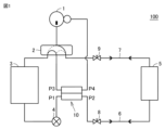
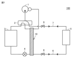
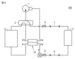
- FIG. 1 is a block diagram showing an air conditioner according to Embodiment 1;
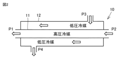
- FIG. 4 is a diagram for explaining an example of a third heat exchanger of the air conditioner according to Embodiment 1;
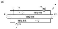
- FIG. 4 is a diagram for explaining another example of the third heat exchanger of the air conditioner according to Embodiment 1;
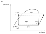
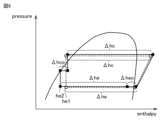
- FIG. The solid line is a Ph diagram (Mollier diagram) showing the relationship between the enthalpy and the pressure of the non-azeotropic refrigerant mixture circulating in the refrigerant circuit when the air conditioner according to Embodiment 1 is in the second state. .
- the dashed line indicates the non-azeotropic refrigerant mixture that circulates in the refrigerant circuit when the air conditioner of Comparative Example 1, which differs from the air conditioner according to Embodiment 1 only in that the third heat exchanger is not provided, is in the second state.
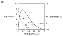
- the solid line indicates the relationship between the mass fraction of R32 (unit: mass %) and the temperature gradient of the non-azeotropic refrigerant mixture (unit: ° C.) when the non-azeotropic refrigerant mixture is a two-component refrigerant mixture containing R32 and R1234yf. It is a graph for explaining the relationship.
- the dashed line represents the mass fraction of R32 (unit: mass %) and the temperature gradient difference (unit: ° C.) of the non-azeotropic mixed refrigerant when the non-azeotropic mixed refrigerant is a two-kind mixed refrigerant containing R32 and R1234yf. It is a graph for explaining the relationship between.
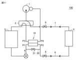
- FIG. 4 is a block diagram showing a modification of the air conditioner according to Embodiment 1.
- FIG. FIG. 11 is a block diagram showing an air conditioner according to Embodiment 3;
- the solid line is a Ph diagram of the non-azeotropic refrigerant mixture circulating in the refrigerant circuit when the air conditioner according to Embodiment 3 is in the second state.
- the dashed line indicates the non-azeotropic refrigerant mixture circulating in the refrigerant circuit when the air conditioner of Comparative Example 2, which differs from the air conditioner according to Embodiment 3 only in that the third heat exchanger is not provided, is in the second state.
- FIG. 11 is a block diagram showing an air conditioner according to Embodiment 4; 4 is a block diagram showing a modification of the air conditioner according to Embodiment 1.
- the air conditioner 100 includes a refrigerant circuit in which a non-azeotropic refrigerant mixture circulates.
- the refrigerant circuit includes a compressor 1, a four-way valve 2, a first heat exchanger 3, a first expansion valve 4, a second heat exchanger 5, a liquid extension pipe 6, a gas extension pipe 7, On-off valves 8 and 9 and a third heat exchanger 10 are provided.
- the four-way valve 2 circulates the non-azeotropic refrigerant mixture sequentially through the compressor 1, the first heat exchanger 3, the first expansion valve 4, the liquid extension pipe 6, the second heat exchanger 5, and the gas extension pipe 7.
- the first heat exchanger 3 acts as a condenser and the second heat exchanger 5 acts as an evaporator.
- the second heat exchanger 5 acts as a condenser and the first heat exchanger 3 acts as an evaporator.
- the compressor 1, the four-way valve 2, the first heat exchanger 3, the first expansion valve 4, the on-off valves 8 and 9, and the third heat exchanger 10 are included in, for example, an outdoor unit.
- the first heat exchanger 3 is an outdoor heat exchanger.
- the second heat exchanger 5 is included in the indoor unit, for example.
- the second heat exchanger 5 is an indoor heat exchanger.
- the first state is realized during cooling operation.
- the second state is realized during heating operation.
- the liquid extension pipe 6 connects between the first expansion valve 4 and the second heat exchanger 5 in the refrigerant circuit.
- the gas extension pipe 7 connects between the four-way valve 2 and the second heat exchanger 5 in the refrigerant circuit.
- the on-off valve 8 is arranged between the first expansion valve 4 and the liquid extension pipe 6 in the refrigerant circuit.
- the on-off valve 9 is arranged between the four-way valve 2 and the gas extension pipe 7 in the refrigerant circuit.
- the non-azeotropic refrigerant mixture flowing between the first expansion valve 4 and the second heat exchanger 5 flows between the four-way valve 2 and the suction port of the compressor 1. It is provided to exchange heat with the mixed refrigerant.
- the non-azeotropic refrigerant mixture flowing between the first expansion valve 4 and the on-off valve 8 flows between the four-way valve 2 and the suction port of the compressor 1. It is provided to exchange heat with the boiling mixed refrigerant.
- the third heat exchanger 10 includes a first inlet/outlet P1 connected to the first expansion valve 4 in the refrigerant circuit, a second inlet/outlet P2 connected to the on-off valve 8 in the refrigerant circuit, It has a third inlet/outlet P3 connected to the four-way valve 2, and a fourth outlet/inlet P4 connected to the suction port of the compressor 1 in the refrigerant circuit.
- the first inlet/outlet P1 and the second inlet/outlet P2 are connected in series with each other.
- the third inlet/outlet P3 and the fourth inlet/outlet P4 are connected in series with each other.
- the third heat exchanger 10 is, for example, a double circular tube heat exchanger.
- the third heat exchanger 10 includes a first pipe 11 having a first inlet P1 and a second inlet P2 and a second pipe 12 having a third inlet P3 and a fourth inlet P4.
- the first pipe 11 passes through the second pipe 12 .
- the third inlet/outlet P3 is arranged above the first pipe 11, for example.
- the fourth inlet/outlet P4 is arranged below the first pipe 11, for example.
- the flow of the non-azeotropic refrigerant mixture in the first pipe 11 of the third heat exchanger 10 and the flow of the non-azeotropic refrigerant mixture in the second pipe 12 are parallel flows.
- the third heat exchanger 10 may be the double circular tube heat exchanger shown in FIG.
- the third inlet/outlet P3 is arranged below the first pipe 11 .
- the fourth inlet/outlet P4 is arranged above the first pipe 11 . In this case, in the second state, the flow of the non-azeotropic refrigerant mixture in the first pipe 11 of the third heat exchanger 10 and the flow of the non-azeotropic refrigerant mixture in the second pipe 12 are countercurrent.
- the third heat exchanger 10 reduces the temperature of the non-azeotropic refrigerant mixture condensed in the second heat exchanger 5 and flows into the first heat exchanger 3. It is provided so as to reduce the dryness of the
- the specific enthalpy of the boiling mixture refrigerant is h2, which is smaller than h1.
- the non-azeotropic refrigerant mixture condensed in the second heat exchanger 5 exchanges heat with the non-azeotropic refrigerant mixture flowing between the four-way valve 2 and the suction port of the compressor 1. This is because it is condensed.
- the non-azeotropic refrigerant mixture flowing out of the third heat exchanger 10 flows into the first heat exchanger 3 after being decompressed and expanded by the first expansion valve 4 .
- the specific enthalpy of the non-azeotropic refrigerant mixture evaporated in the first heat exchanger 3 increases by ⁇ he from h2.
- the second heat exchanger 5 As indicated by the dashed line in FIG. 4, in the air conditioner of Comparative Example 1, which differs from the air conditioner 100 only in that the third heat exchanger 10 is not provided, in the second state, the second heat exchanger 5
- the non-azeotropic refrigerant mixture having a specific enthalpy of h1 condensed at is decompressed and expanded by the first expansion valve 4 without flowing through the third heat exchanger 10, and then flows into the first heat exchanger 3. .
- the specific enthalpy of the non-azeotropic refrigerant mixture evaporated in the first heat exchanger 3 increases by ⁇ he from h1.
- the amount of change ⁇ hc in the specific enthalpy of the non-azeotropic refrigerant mixture in the condenser is the same, and the non-azeotropic refrigerant mixture in the evaporator
- the amount of change ⁇ he in the specific enthalpy of the mixed refrigerant is also equal to each other.
- the amount of change ⁇ hco in the specific enthalpy of the high-pressure non-azeotropic refrigerant mixture in the third heat exchanger 10 is the amount of change ⁇ heo in the specific enthalpy of the low-pressure non-azeotropic refrigerant mixture in the third heat exchanger 10. is equal to Therefore, in the air conditioner 100, the Ph diagram in the second state shifts to the left (lower enthalpy side) by ⁇ hco compared to the air conditioner of Comparative Example 1.
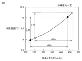
- the non-azeotropic refrigerant mixture enclosed in the refrigerant circuit of the air conditioner 100 is adjusted so that the relationship between the specific enthalpy and the refrigerant temperature shown in FIG. 5 is established. Specifically, the temperature of the non-azeotropic refrigerant mixture enclosed in the refrigerant circuit of the air conditioner 100 decreases as the specific enthalpy decreases, and the specific enthalpy increases by ⁇ he from a relatively low temperature state.
- the temperature rise width ⁇ T1 when the temperature is relatively high is smaller than the temperature rise width ⁇ T2 when the specific enthalpy rises by ⁇ he from a relatively high temperature state.
- the Ph diagram in the second state shifts to the left, and the specific enthalpy of the non-azeotropic refrigerant mixture flowing into the first heat exchanger 3 is smaller and the non-azeotropic refrigerant mixture has the characteristics shown in FIG. Therefore, the temperature of the non-azeotropic refrigerant mixture flowing into the first heat exchanger 3 (evaporator) of the air conditioner 100 is higher than the temperature of the non-azeotropic refrigerant mixture flowing into the evaporator of the air conditioner of Comparative Example 1. can also be set higher.
- the air conditioner 100 compared to the air conditioner of Comparative Example 1, it is easier to ensure the temperature difference between the non-azeotropic refrigerant mixture flowing through the first heat exchanger 3 and the air in the second state, and frost formation The occurrence of As a result, in the air conditioner 100, the performance in the second state is improved as compared with the air conditioner of Comparative Example 1.
- An example of a non-azeotropic refrigerant mixture adjusted to establish the relationship between the specific enthalpy and the refrigerant temperature shown in FIG. 5 is a two-kind refrigerant mixture of R32 and R1234yf.
- the mass fraction of R32 in this two-kind mixed refrigerant is 30% by mass or more.
- the mass fraction of R32 in this two-kind mixed refrigerant is, for example, 40% by mass or more.
- the temperature gradient of the non-azeotropic refrigerant mixture composed of R32 and R1234yf changes according to the mass fraction of R32. If the mass fraction of R32 is less than 30%, the higher the mass fraction of R32, the more the temperature gradient of the non-azeotropic refrigerant mixture exhibits an upwardly convex peak shape. If the mass fraction of R32 is 30 mass % or more, the temperature gradient of the non-azeotropic refrigerant mixture becomes smaller as the mass fraction of R32 increases.
- the temperature gradient difference of the non-azeotropic refrigerant mixture indicated by the dashed line in FIG. 6 indicates the amount of change in the temperature gradient of the non-azeotropic refrigerant mixture when the mass fraction of R32 is increased or decreased by 1%.
- the temperature gradient difference of the non-azeotropic refrigerant mixture when the mass fraction of R32 is 30% is the temperature gradient of the non-azeotropic refrigerant mixture when the mass fraction of R32 is 30% and the mass fraction of R32 2 shows the difference from the temperature gradient of the non-azeotropic refrigerant mixture when the ratio is 31%.
- the temperature gradient difference is smaller than when the mass fraction of R32 is less than 30%. Therefore, when the mass fraction of R32 in the non-azeotropic refrigerant mixture composed of R32 and R1234yf is 30% by mass or more, the amount of the non-azeotropic refrigerant mixture is lower than when the mass fraction of R32 is less than 30%.
- the temperature rise width ⁇ T1 becomes smaller.
- the third heat exchanger 10 includes a refrigerant pipe connecting the first expansion valve 4 and the second heat exchanger 5, the four-way valve 2 and the suction port of the compressor 1. It may be configured as a heat transfer member that thermally connects the refrigerant pipe line that connects between.
- a material forming the heat transfer member includes, for example, aluminum (Al) or copper (Cu).
- Embodiment 2 The air conditioner according to the second embodiment has basically the same configuration as the air conditioner 100 according to the first embodiment, but the non-azeotropic mixture refrigerants sealed in the refrigerant circuit are R32, R1234yf, and R1234yf. It differs from the air conditioner 100 in that it is a three-kind mixed refrigerant consisting of R1123.
- the non-azeotropic refrigerant mixture enclosed in the refrigerant circuit of the air conditioner according to Embodiment 2 is also adjusted so that the relationship between the specific enthalpy and the refrigerant temperature shown in FIG. 5 is established.
- the mass fraction of R32 is 18% by mass or more, and the mass fraction of R1234yf is lower than the mass fraction of R1123.
- the sum of the mass fraction of R32 and the mass fraction of R1123 is 60% by mass or more.
- an air conditioner of Comparative Example 4 consider an air conditioner that differs from the air conditioner 100 only in the mass fraction in the three-kind mixed refrigerant consisting of R32, R1234yf, and R1123.
- the mass fraction of R32 is less than 18 mass % and the mass fraction of R1234yf is higher than the mass fraction of R1123.
- Such a non-azeotropic mixed refrigerant does not satisfy the relationship between the specific enthalpy and the refrigerant temperature shown in FIG.
- the non-azeotropic refrigerant mixture contains relatively more R32 and R1123 than the air conditioner of Comparative Example 4, and the non-azeotropic refrigerant mixture has the characteristics shown in FIG. have.
- the thermophysical properties of the non-azeotropic mixed refrigerant calculated by the refrigerant physical property calculation software (REFPROP manufactured by National Institute of Standards and Technology (NIST)).
- the temperature gradient of the non-azeotropic refrigerant mixture in the second embodiment is about 52% of the temperature gradient of the non-azeotropic refrigerant mixture in the fourth comparative example.
- the air conditioner according to Embodiment 2 compared to the air conditioner in Comparative Example 4, the temperature difference between the non-azeotropic refrigerant mixture flowing through the first heat exchanger 3 and the air in the second state is ensured. It is easy to do, and the occurrence of frost formation is suppressed.
- the compressor suction density (the gas density of the non-azeotropic refrigerant mixture sucked into the compressor 1) in Embodiment 2 is higher than the compressor suction density in Comparative Example 4.
- the compressor suction density of the non-azeotropic refrigerant mixture in Embodiment 2 is about 23% higher than the compressor suction density of the non-azeotropic refrigerant mixture in Comparative Example 4. get higher
- the non-azeotropic refrigerant mixture circulation amount for exhibiting the rated capacity during cooling operation (first state) is Since they are substantially the same, the higher the compressor suction density, the slower the flow velocity of the non-azeotropic refrigerant mixture flowing through the gas extension pipe 7, so the pressure loss of the non-azeotropic refrigerant mixture in the gas extension pipe 7 becomes smaller.
- the air conditioner of Comparative Example 4 it is necessary to increase the frequency of the compressor in order to secure the capacity.
- the mass fraction of R32 is 19% by mass or more and 30% by mass or less.
- the mass fraction of R1234yf is 11% by mass or more and 25% by mass or less.
- the mass fraction of R1123 is 45% by mass or more and 70% by mass or less.
- the air conditioner 101 according to Embodiment 3 has basically the same configuration as the air conditioner 100 according to Embodiment 1, but instead of the third heat exchanger 10, It differs from the air conditioner 100 in that it includes a third heat exchanger 13 and further includes a second expansion valve 14 .
- the refrigerant circuit of the air conditioner 101 includes a receiver tank 15 that stores a portion of the non-azeotropic refrigerant mixture flowing between the first expansion valve 4 and the second heat exchanger 5, and a receiver tank A second expansion valve 14 for reducing the pressure of the non-azeotropic refrigerant mixture flowing between 15 and the second heat exchanger 5, and the four-way valve 2 and the suction port of the compressor 1 are connected and connected.
- Refrigerant line 16 which section extends into receiver tank 15 .
- the third heat exchanger 13 is configured as a receiver, and includes a receiver tank 15 and a part of the refrigerant pipe line 16 passing through the receiver tank 15 .
- the non-azeotropic refrigerant mixture enclosed in the refrigerant circuit of the air conditioner 101 is the non-azeotropic refrigerant mixture enclosed in the refrigerant circuit of the air conditioner 100 according to Embodiment 1, or the refrigerant mixture according to Embodiment 2. It may be the same as the non-azeotropic mixed refrigerant sealed in the refrigerant circuit of the air conditioner.
- the third heat exchanger 13 reduces the temperature of the non-azeotropic refrigerant mixture condensed in the second heat exchanger 5 and flows into the first heat exchanger 3. It is provided so as to reduce the dryness of the
- the third heat The specific enthalpy of the non-azeotropic refrigerant mixture flowing out of the exchanger 13 is h2, which is smaller than h1.
- the non-azeotropic refrigerant mixture condensed in the second heat exchanger 5 exchanges heat with the non-azeotropic refrigerant mixture flowing between the four-way valve 2 and the suction port of the compressor 1. This is because it is condensed.
- the non-azeotropic refrigerant mixture flowing out of the third heat exchanger 13 flows into the first heat exchanger 3 via the first expansion valve 4 .
- the specific enthalpy of the non-azeotropic refrigerant mixture evaporated in the first heat exchanger 3 increases by ⁇ he from h2.
- the air conditioner of Comparative Example 2 which differs from the air conditioner 100 only in that the third heat exchanger 13 and the second expansion valve 14 are not provided, in the second state:
- the non-azeotropic refrigerant mixture having a specific enthalpy of h1 condensed in the second heat exchanger 5 does not flow through the third heat exchanger 13, and after being decompressed and expanded in the first expansion valve 4, the first heat It flows into exchanger 3 .
- the specific enthalpy of the non-azeotropic refrigerant mixture evaporated in the first heat exchanger 3 increases by ⁇ he from h1.
- the amount of change ⁇ hc in the specific enthalpy of the non-azeotropic refrigerant mixture in the condenser is equal to each other, and the non-azeotropic refrigerant mixture in the evaporator
- the amount of change ⁇ he in the specific enthalpy of the mixed refrigerant is also equal to each other.
- the amount of change ⁇ hco in the specific enthalpy of the high-pressure non-azeotropic refrigerant mixture in the third heat exchanger 13 is the amount of change ⁇ heo in the specific enthalpy of the low-pressure non-azeotropic refrigerant mixture in the third heat exchanger 13. is equal to Therefore, in the air conditioner 101, the Ph diagram in the second state shifts to the left (lower enthalpy side) by ⁇ hco compared to the air conditioner of the second comparative example.
- the air conditioner 101 since the air conditioner 101 has basically the same configuration as the air conditioner 100 and the air conditioner according to Embodiment 2, it can exhibit the same effects.
- the air conditioner 102 according to Embodiment 4 has basically the same configuration as the air conditioner 100 according to Embodiment 1, except that the third heat exchanger 10 is the first heat exchanger.
- the non-azeotropic refrigerant mixture flowing between the heat exchanger 3 and the first expansion valve 4 exchanges heat with the non-azeotropic refrigerant mixture flowing between the four-way valve 2 and the suction port of the compressor 1. It differs from the air conditioner 100 in that
- the third heat exchanger 10 reduces the temperature of the non-azeotropic refrigerant mixture condensed in the first heat exchanger 3 in the first state, and flows into the second heat exchanger 5. It is provided so as to reduce the dryness of the non-azeotropic refrigerant mixture.
- the non-azeotropic refrigerant mixture enclosed in the refrigerant circuit of the air conditioner 102 is the non-azeotropic refrigerant mixture enclosed in the refrigerant circuit of the air conditioner 100 according to Embodiment 1, or the refrigerant mixture according to Embodiment 2. It may be the same as the non-azeotropic mixed refrigerant sealed in the refrigerant circuit of the air conditioner.
- a Ph diagram of the non-azeotropic refrigerant mixture circulating in the refrigerant circuit when the air conditioner 102 is in the first state is the same as the Ph diagram of FIG.
- the second heat exchanger 5 It is easy to ensure a temperature difference between the non-azeotropic refrigerant mixture flowing through the air and the air, and the performance in the first state is improved.
- Air conditioners 100 to 102 according to Embodiments 1 to 4 can adopt the modification shown in FIG.
- the refrigerant circuit of the air conditioners 100 and 101 includes a bypass passage 20 connecting between the first expansion valve 4 and the on-off valve 8 and bypassing the third heat exchanger 10. and an on-off valve 21 for opening and closing the bypass channel 20 may be further included.
- the on-off valve 21 is, for example, opened in the first state and closed in the second state.
- the refrigerant circuit of the air conditioner 102 includes a bypass flow path connecting between the first expansion valve 4 and the first heat exchanger 3 and bypassing the third heat exchanger 10, a bypass flow path It may further include an on-off valve that opens and closes the.
Landscapes
- Engineering & Computer Science (AREA)
- Physics & Mathematics (AREA)
- Thermal Sciences (AREA)
- Mechanical Engineering (AREA)
- General Engineering & Computer Science (AREA)
- Chemical & Material Sciences (AREA)
- Chemical Kinetics & Catalysis (AREA)
- Combustion & Propulsion (AREA)
- Materials Engineering (AREA)
- Organic Chemistry (AREA)
- Compression-Type Refrigeration Machines With Reversible Cycles (AREA)
Abstract
Description
実施の形態1.
実施の形態1に係る空気調和機100は、非共沸混合冷媒が循環する冷媒回路を備える。図1に示されるように、冷媒回路は、圧縮機1、四方弁2、第1熱交換器3、第1膨張弁4、第2熱交換器5、液延長配管6、ガス延長配管7、開閉弁8,9、および第3熱交換器10を備える。
図7に示されるように、第3熱交換器10は、第1膨張弁4と第2熱交換器5との間を接続する冷媒管路と、四方弁2と圧縮機1の吸入口との間を接続する冷媒管路とを熱的に接続する伝熱部材として構成されていてもよい。伝熱部材を構成する材料は、例えばアルミニウム(Al)または銅(Cu)を含む。
実施の形態2に係る空気調和機は、実施の形態1に係る空気調和機100と基本的に同様の構成を備えるが、冷媒回路に封入されている非共沸混合冷媒がR32、R1234yf、およびR1123からなる3種混合冷媒である点で、空気調和機100とは異なる。
図8に示されるように、実施の形態3に係る空気調和機101は、実施の形態1に係る空気調和機100と基本的に同様の構成を備えるが、第3熱交換器10に代えて第3熱交換器13を備えており、さらに第2膨張弁14を備えている点で、空気調和機100とは異なる。
図10に示されるように、実施の形態4に係る空気調和機102は、実施の形態1に係る空気調和機100と基本的に同様の構成を備えるが、第3熱交換器10が第1熱交換器3と第1膨張弁4との間を流れる非共沸混合冷媒が四方弁2と圧縮機1の吸入口との間を流れる非共沸混合冷媒と熱交換するように設けられている点で、空気調和機100とは異なる。
実施の形態1~4に係る空気調和機100~102は、図11に示される変形例を採り得る。図11に示されるように、空気調和機100,101の冷媒回路は、第1膨張弁4と開閉弁8との間を接続しておりかつ第3熱交換器10をバイパスするバイパス流路20と、バイパス流路20を開閉する開閉弁21とをさらに含んでいてもよい。この場合、開閉弁21は、例えば第1状態において開放され、第2状態において閉止される。同様に、空気調和機102の冷媒回路は、第1膨張弁4と第1熱交換器3との間を接続しておりかつ第3熱交換器10をバイパスするバイパス流路と、バイパス流路を開閉する開閉弁とをさらに含んでいてもよい。
Claims (7)
- 非共沸混合冷媒が循環する冷媒回路を備え、
前記冷媒回路は、圧縮機、四方弁、第1熱交換器、第1膨張弁、および第2熱交換器を含み、
前記四方弁は、前記非共沸混合冷媒が前記圧縮機、前記第1熱交換器、前記第1膨張弁、および前記第2熱交換器を順に循環する第1状態と、前記非共沸混合冷媒が前記圧縮機、前記第2熱交換器、前記第1膨張弁、および前記第1熱交換器を順に循環する第2状態とを切り替え、
前記冷媒回路は、
前記第1熱交換器と前記第1膨張弁との間を流れる前記非共沸混合冷媒または前記第1膨張弁と前記第2熱交換器との間を流れる前記非共沸混合冷媒が、前記四方弁と前記圧縮機の吸入口との間を流れる前記非共沸混合冷媒と熱交換するように設けられている第3熱交換器とをさらに含み、
前記非共沸混合冷媒は、R32およびR1234yfからなる2種混合冷媒であり、
前記非共沸混合冷媒中のR32の質量分率が30質量%以上である、空気調和機。 - 非共沸混合冷媒が循環する冷媒回路を備え、
前記冷媒回路は、圧縮機、四方弁、第1熱交換器、第1膨張弁、および第2熱交換器を含み、
前記四方弁は、前記非共沸混合冷媒が前記圧縮機、前記第1熱交換器、前記第1膨張弁、および前記第2熱交換器を順に循環する第1状態と、前記非共沸混合冷媒が前記圧縮機、前記第2熱交換器、前記第1膨張弁、および前記第1熱交換器を順に循環する第2状態とを切り替え、
前記冷媒回路は、
前記第1熱交換器と前記第1膨張弁との間を流れる前記非共沸混合冷媒または前記第1膨張弁と前記第2熱交換器との間を流れる前記非共沸混合冷媒が、前記四方弁と前記圧縮機の吸入口との間を流れる前記非共沸混合冷媒と熱交換するように設けられている第3熱交換器とをさらに含み、
前記非共沸混合冷媒は、R32、R1234yf、およびR1123からなる3種混合冷媒であり、
前記非共沸混合冷媒において、R32の質量分率が18質量%以上であり、R1234yfの質量分率がR1123の質量分率よりも低い、空気調和機。 - 前記非共沸混合冷媒において、R32の質量分率が、R1234yfの質量分率よりも高く、R1123の質量分率よりも低い、請求項2に記載の空気調和機。
- 前記非共沸混合冷媒において、R32の質量分率が20質量%以上であり、R1234yfの質量分率が20%未満であり、R1123の質量分率が60質量%以上である、請求項3に記載の空気調和機。
- 前記第1熱交換器は、室外熱交換器であり、
前記第2熱交換器は、室内熱交換器であり、
前記第3熱交換器は、前記第1膨張弁と前記第2熱交換器との間を流れる前記非共沸混合冷媒が、前記四方弁と前記圧縮機の前記吸入口との間を流れる前記非共沸混合冷媒と熱交換するように設けられている、請求項1~4のいずれか1項に記載の空気調和機。 - 前記冷媒回路は、
前記第1膨張弁と前記第2熱交換器との間を流れる前記非共沸混合冷媒の一部を貯留するレシーバタンクと、
前記レシーバタンクと前記第2熱交換器との間を流れる前記非共沸混合冷媒を減圧するための第2膨張弁と、
前記四方弁と前記吸入口との間を接続する冷媒管路とをさらに含み、
前記冷媒管路の一部が前記レシーバタンクの内部に渡されており、
前記第3熱交換器は、前記レシーバタンクと、前記レシーバタンク内に渡されている前記冷媒管路の一部とを含む、請求項5に記載の空気調和機。 - 前記第1熱交換器は、室外熱交換器であり、
前記第2熱交換器は、室内熱交換器であり、
前記第3熱交換器は、前記第1熱交換器と前記第1膨張弁との間を流れる前記非共沸混合冷媒が、前記四方弁と前記圧縮機の前記吸入口との間を流れる前記非共沸混合冷媒と熱交換するように設けられている、請求項1~4のいずれか1項に記載の空気調和機。
Priority Applications (5)
| Application Number | Priority Date | Filing Date | Title |
|---|---|---|---|
| US18/705,644 US20250003655A1 (en) | 2021-11-25 | 2021-11-25 | Air conditioner |
| CN202180104318.2A CN118265878A (zh) | 2021-11-25 | 2021-11-25 | 空调机 |
| EP21965632.9A EP4438974A4 (en) | 2021-11-25 | 2021-11-25 | Air conditioner |
| PCT/JP2021/043245 WO2023095260A1 (ja) | 2021-11-25 | 2021-11-25 | 空気調和機 |
| JP2023563424A JPWO2023095260A1 (ja) | 2021-11-25 | 2021-11-25 |
Applications Claiming Priority (1)
| Application Number | Priority Date | Filing Date | Title |
|---|---|---|---|
| PCT/JP2021/043245 WO2023095260A1 (ja) | 2021-11-25 | 2021-11-25 | 空気調和機 |
Publications (1)
| Publication Number | Publication Date |
|---|---|
| WO2023095260A1 true WO2023095260A1 (ja) | 2023-06-01 |
Family
ID=86539170
Family Applications (1)
| Application Number | Title | Priority Date | Filing Date |
|---|---|---|---|
| PCT/JP2021/043245 Ceased WO2023095260A1 (ja) | 2021-11-25 | 2021-11-25 | 空気調和機 |
Country Status (5)
| Country | Link |
|---|---|
| US (1) | US20250003655A1 (ja) |
| EP (1) | EP4438974A4 (ja) |
| JP (1) | JPWO2023095260A1 (ja) |
| CN (1) | CN118265878A (ja) |
| WO (1) | WO2023095260A1 (ja) |
Citations (5)
| Publication number | Priority date | Publication date | Assignee | Title |
|---|---|---|---|---|
| JPH0875290A (ja) | 1994-09-06 | 1996-03-19 | Hitachi Ltd | ヒートポンプ式空調装置 |
| WO2020003494A1 (ja) * | 2018-06-29 | 2020-01-02 | 三菱電機株式会社 | 冷凍サイクル装置 |
| JP2021102745A (ja) * | 2019-12-25 | 2021-07-15 | ダイキン工業株式会社 | 冷凍サイクル装置、冷凍機油および冷媒漏洩防止剤 |
| WO2021205536A1 (ja) * | 2020-04-07 | 2021-10-14 | 三菱電機株式会社 | 冷凍サイクル装置 |
| JP2021178884A (ja) * | 2020-05-11 | 2021-11-18 | Eneos株式会社 | 冷凍機油及び冷凍機用作動流体組成物 |
Family Cites Families (9)
| Publication number | Priority date | Publication date | Assignee | Title |
|---|---|---|---|---|
| US4030315A (en) * | 1975-09-02 | 1977-06-21 | Borg-Warner Corporation | Reverse cycle heat pump |
| JPH085204A (ja) * | 1994-06-16 | 1996-01-12 | Mitsubishi Heavy Ind Ltd | 冷凍サイクル装置 |
| EP0962725B1 (en) * | 1997-12-16 | 2017-11-08 | Panasonic Corporation | Airconditioner using inflammable refrigerant |
| JP4062129B2 (ja) * | 2003-03-05 | 2008-03-19 | 株式会社デンソー | 蒸気圧縮式冷凍機 |
| JP2009250592A (ja) * | 2008-04-11 | 2009-10-29 | Daikin Ind Ltd | 冷凍装置 |
| MY180052A (en) * | 2014-11-11 | 2020-11-20 | Trane Int Inc | Refrigerant compositions and methods of use |
| JP6418284B1 (ja) * | 2017-06-12 | 2018-11-07 | ダイキン工業株式会社 | 冷媒を含有する組成物、その使用、それを用いた冷凍方法、及びそれを含む冷凍機 |
| US11506425B2 (en) * | 2017-12-18 | 2022-11-22 | Daikin Industries, Ltd. | Refrigeration cycle apparatus |
| EP3779326B1 (en) * | 2018-04-11 | 2023-11-29 | Mitsubishi Electric Corporation | Refrigeration cycle device |
-
2021
- 2021-11-25 EP EP21965632.9A patent/EP4438974A4/en not_active Withdrawn
- 2021-11-25 WO PCT/JP2021/043245 patent/WO2023095260A1/ja not_active Ceased
- 2021-11-25 US US18/705,644 patent/US20250003655A1/en not_active Abandoned
- 2021-11-25 CN CN202180104318.2A patent/CN118265878A/zh not_active Withdrawn
- 2021-11-25 JP JP2023563424A patent/JPWO2023095260A1/ja active Pending
Patent Citations (5)
| Publication number | Priority date | Publication date | Assignee | Title |
|---|---|---|---|---|
| JPH0875290A (ja) | 1994-09-06 | 1996-03-19 | Hitachi Ltd | ヒートポンプ式空調装置 |
| WO2020003494A1 (ja) * | 2018-06-29 | 2020-01-02 | 三菱電機株式会社 | 冷凍サイクル装置 |
| JP2021102745A (ja) * | 2019-12-25 | 2021-07-15 | ダイキン工業株式会社 | 冷凍サイクル装置、冷凍機油および冷媒漏洩防止剤 |
| WO2021205536A1 (ja) * | 2020-04-07 | 2021-10-14 | 三菱電機株式会社 | 冷凍サイクル装置 |
| JP2021178884A (ja) * | 2020-05-11 | 2021-11-18 | Eneos株式会社 | 冷凍機油及び冷凍機用作動流体組成物 |
Non-Patent Citations (1)
| Title |
|---|
| See also references of EP4438974A4 |
Also Published As
| Publication number | Publication date |
|---|---|
| JPWO2023095260A1 (ja) | 2023-06-01 |
| CN118265878A (zh) | 2024-06-28 |
| EP4438974A1 (en) | 2024-10-02 |
| US20250003655A1 (en) | 2025-01-02 |
| EP4438974A4 (en) | 2024-11-27 |
Similar Documents
| Publication | Publication Date | Title |
|---|---|---|
| JP5318099B2 (ja) | 冷凍サイクル装置、並びにその制御方法 | |
| US11175080B2 (en) | Refrigeration cycle apparatus having heat exchanger switchable between parallel and series connection | |
| WO1998006983A1 (en) | Air conditioner | |
| WO2019091241A1 (zh) | 空调制冷循环系统及空调器 | |
| JP5049888B2 (ja) | 冷凍サイクル装置 | |
| WO2011092802A1 (ja) | ヒートポンプ装置及び冷媒バイパス方法 | |
| CN103765124A (zh) | 制冷装置 | |
| EP3534082B1 (en) | Air conditioner | |
| WO2011105270A1 (ja) | 冷凍サイクル装置 | |
| JP2017161182A (ja) | ヒートポンプ装置 | |
| CN101317046A (zh) | 冷冻装置 | |
| WO2020071293A1 (ja) | 冷凍サイクル装置 | |
| JP6643630B2 (ja) | 空気調和装置 | |
| CN116438413A (zh) | 制冷循环装置 | |
| JP2007240025A (ja) | 冷凍装置 | |
| JP4608303B2 (ja) | 蒸気圧縮式ヒートポンプ | |
| JP2019060545A (ja) | 空気調和機 | |
| JP3953976B2 (ja) | 空気調和装置 | |
| AU2824000A (en) | Refrigerating device | |
| JP2000146258A (ja) | 空気調和機およびその制御方法 | |
| JP7584683B2 (ja) | 空気調和機および空気調和機の制御方法 | |
| US12215897B2 (en) | Air conditioning apparatus and outdoor unit | |
| US20250003655A1 (en) | Air conditioner | |
| WO2020004125A1 (ja) | 冷凍サイクル及び温水ヒートポンプ | |
| JP7858926B2 (ja) | 冷凍サイクル装置 |
Legal Events
| Date | Code | Title | Description |
|---|---|---|---|
| 121 | Ep: the epo has been informed by wipo that ep was designated in this application |
Ref document number: 21965632 Country of ref document: EP Kind code of ref document: A1 |
|
| WWE | Wipo information: entry into national phase |
Ref document number: 18705644 Country of ref document: US |
|
| ENP | Entry into the national phase |
Ref document number: 2023563424 Country of ref document: JP Kind code of ref document: A |
|
| WWE | Wipo information: entry into national phase |
Ref document number: 202180104318.2 Country of ref document: CN |
|
| WWE | Wipo information: entry into national phase |
Ref document number: 2021965632 Country of ref document: EP |
|
| NENP | Non-entry into the national phase |
Ref country code: DE |
|
| ENP | Entry into the national phase |
Ref document number: 2021965632 Country of ref document: EP Effective date: 20240625 |
|
| WWW | Wipo information: withdrawn in national office |
Ref document number: 2021965632 Country of ref document: EP |