WO2023095300A1 - 分離部材および分離方法 - Google Patents
分離部材および分離方法 Download PDFInfo
- Publication number
- WO2023095300A1 WO2023095300A1 PCT/JP2021/043443 JP2021043443W WO2023095300A1 WO 2023095300 A1 WO2023095300 A1 WO 2023095300A1 JP 2021043443 W JP2021043443 W JP 2021043443W WO 2023095300 A1 WO2023095300 A1 WO 2023095300A1
- Authority
- WO
- WIPO (PCT)
- Prior art keywords
- separation
- layer
- zeolite
- separation member
- porous support
- Prior art date
- Legal status (The legal status is an assumption and is not a legal conclusion. Google has not performed a legal analysis and makes no representation as to the accuracy of the status listed.)
- Ceased
Links
Images


Classifications
-
- B—PERFORMING OPERATIONS; TRANSPORTING
- B01—PHYSICAL OR CHEMICAL PROCESSES OR APPARATUS IN GENERAL
- B01D—SEPARATION
- B01D53/00—Separation of gases or vapours; Recovering vapours of volatile solvents from gases; Chemical or biological purification of waste gases, e.g. engine exhaust gases, smoke, fumes, flue gases, aerosols
- B01D53/22—Separation of gases or vapours; Recovering vapours of volatile solvents from gases; Chemical or biological purification of waste gases, e.g. engine exhaust gases, smoke, fumes, flue gases, aerosols by diffusion
-
- B—PERFORMING OPERATIONS; TRANSPORTING
- B01—PHYSICAL OR CHEMICAL PROCESSES OR APPARATUS IN GENERAL
- B01D—SEPARATION
- B01D53/00—Separation of gases or vapours; Recovering vapours of volatile solvents from gases; Chemical or biological purification of waste gases, e.g. engine exhaust gases, smoke, fumes, flue gases, aerosols
- B01D53/02—Separation of gases or vapours; Recovering vapours of volatile solvents from gases; Chemical or biological purification of waste gases, e.g. engine exhaust gases, smoke, fumes, flue gases, aerosols by adsorption, e.g. preparative gas chromatography
-
- B—PERFORMING OPERATIONS; TRANSPORTING
- B01—PHYSICAL OR CHEMICAL PROCESSES OR APPARATUS IN GENERAL
- B01D—SEPARATION
- B01D53/00—Separation of gases or vapours; Recovering vapours of volatile solvents from gases; Chemical or biological purification of waste gases, e.g. engine exhaust gases, smoke, fumes, flue gases, aerosols
- B01D53/22—Separation of gases or vapours; Recovering vapours of volatile solvents from gases; Chemical or biological purification of waste gases, e.g. engine exhaust gases, smoke, fumes, flue gases, aerosols by diffusion
- B01D53/228—Separation of gases or vapours; Recovering vapours of volatile solvents from gases; Chemical or biological purification of waste gases, e.g. engine exhaust gases, smoke, fumes, flue gases, aerosols by diffusion characterised by specific membranes
-
- B—PERFORMING OPERATIONS; TRANSPORTING
- B01—PHYSICAL OR CHEMICAL PROCESSES OR APPARATUS IN GENERAL
- B01D—SEPARATION
- B01D67/00—Processes specially adapted for manufacturing semi-permeable membranes for separation processes or apparatus
- B01D67/0039—Inorganic membrane manufacture
- B01D67/0051—Inorganic membrane manufacture by controlled crystallisation, e,.g. hydrothermal growth
-
- B—PERFORMING OPERATIONS; TRANSPORTING
- B01—PHYSICAL OR CHEMICAL PROCESSES OR APPARATUS IN GENERAL
- B01D—SEPARATION
- B01D69/00—Semi-permeable membranes for separation processes or apparatus characterised by their form, structure or properties; Manufacturing processes specially adapted therefor
- B01D69/10—Supported membranes; Membrane supports
- B01D69/105—Support pretreatment
-
- B—PERFORMING OPERATIONS; TRANSPORTING
- B01—PHYSICAL OR CHEMICAL PROCESSES OR APPARATUS IN GENERAL
- B01D—SEPARATION
- B01D69/00—Semi-permeable membranes for separation processes or apparatus characterised by their form, structure or properties; Manufacturing processes specially adapted therefor
- B01D69/12—Composite membranes; Ultra-thin membranes
-
- B—PERFORMING OPERATIONS; TRANSPORTING
- B01—PHYSICAL OR CHEMICAL PROCESSES OR APPARATUS IN GENERAL
- B01D—SEPARATION
- B01D71/00—Semi-permeable membranes for separation processes or apparatus characterised by the material; Manufacturing processes specially adapted therefor
- B01D71/02—Inorganic material
- B01D71/028—Molecular sieves
- B01D71/0281—Zeolites
-
- C—CHEMISTRY; METALLURGY
- C04—CEMENTS; CONCRETE; ARTIFICIAL STONE; CERAMICS; REFRACTORIES
- C04B—LIME, MAGNESIA; SLAG; CEMENTS; COMPOSITIONS THEREOF, e.g. MORTARS, CONCRETE OR LIKE BUILDING MATERIALS; ARTIFICIAL STONE; CERAMICS; REFRACTORIES; TREATMENT OF NATURAL STONE
- C04B41/00—After-treatment of mortars, concrete, artificial stone or ceramics; Treatment of natural stone
- C04B41/009—After-treatment of mortars, concrete, artificial stone or ceramics; Treatment of natural stone characterised by the material treated
-
- C—CHEMISTRY; METALLURGY
- C04—CEMENTS; CONCRETE; ARTIFICIAL STONE; CERAMICS; REFRACTORIES
- C04B—LIME, MAGNESIA; SLAG; CEMENTS; COMPOSITIONS THEREOF, e.g. MORTARS, CONCRETE OR LIKE BUILDING MATERIALS; ARTIFICIAL STONE; CERAMICS; REFRACTORIES; TREATMENT OF NATURAL STONE
- C04B41/00—After-treatment of mortars, concrete, artificial stone or ceramics; Treatment of natural stone
- C04B41/45—Coating or impregnating, e.g. injection in masonry, partial coating of green or fired ceramics, organic coating compositions for adhering together two concrete elements
- C04B41/4505—Coating or impregnating, e.g. injection in masonry, partial coating of green or fired ceramics, organic coating compositions for adhering together two concrete elements characterised by the method of application
- C04B41/4535—Coating or impregnating, e.g. injection in masonry, partial coating of green or fired ceramics, organic coating compositions for adhering together two concrete elements characterised by the method of application applied as a solution, emulsion, dispersion or suspension
- C04B41/4539—Coating or impregnating, e.g. injection in masonry, partial coating of green or fired ceramics, organic coating compositions for adhering together two concrete elements characterised by the method of application applied as a solution, emulsion, dispersion or suspension as a emulsion, dispersion or suspension
-
- C—CHEMISTRY; METALLURGY
- C04—CEMENTS; CONCRETE; ARTIFICIAL STONE; CERAMICS; REFRACTORIES
- C04B—LIME, MAGNESIA; SLAG; CEMENTS; COMPOSITIONS THEREOF, e.g. MORTARS, CONCRETE OR LIKE BUILDING MATERIALS; ARTIFICIAL STONE; CERAMICS; REFRACTORIES; TREATMENT OF NATURAL STONE
- C04B41/00—After-treatment of mortars, concrete, artificial stone or ceramics; Treatment of natural stone
- C04B41/45—Coating or impregnating, e.g. injection in masonry, partial coating of green or fired ceramics, organic coating compositions for adhering together two concrete elements
- C04B41/50—Coating or impregnating, e.g. injection in masonry, partial coating of green or fired ceramics, organic coating compositions for adhering together two concrete elements with inorganic materials
- C04B41/5024—Silicates
-
- C—CHEMISTRY; METALLURGY
- C04—CEMENTS; CONCRETE; ARTIFICIAL STONE; CERAMICS; REFRACTORIES
- C04B—LIME, MAGNESIA; SLAG; CEMENTS; COMPOSITIONS THEREOF, e.g. MORTARS, CONCRETE OR LIKE BUILDING MATERIALS; ARTIFICIAL STONE; CERAMICS; REFRACTORIES; TREATMENT OF NATURAL STONE
- C04B2111/00—Mortars, concrete or artificial stone or mixtures to prepare them, characterised by specific function, property or use
- C04B2111/00474—Uses not provided for elsewhere in C04B2111/00
- C04B2111/00793—Uses not provided for elsewhere in C04B2111/00 as filters or diaphragms
- C04B2111/00801—Membranes; Diaphragms
-
- Y—GENERAL TAGGING OF NEW TECHNOLOGICAL DEVELOPMENTS; GENERAL TAGGING OF CROSS-SECTIONAL TECHNOLOGIES SPANNING OVER SEVERAL SECTIONS OF THE IPC; TECHNICAL SUBJECTS COVERED BY FORMER USPC CROSS-REFERENCE ART COLLECTIONS [XRACs] AND DIGESTS
- Y02—TECHNOLOGIES OR APPLICATIONS FOR MITIGATION OR ADAPTATION AGAINST CLIMATE CHANGE
- Y02C—CAPTURE, STORAGE, SEQUESTRATION OR DISPOSAL OF GREENHOUSE GASES [GHG]
- Y02C20/00—Capture or disposal of greenhouse gases
- Y02C20/40—Capture or disposal of greenhouse gases of CO2
Definitions
- the present invention relates to a separating member and a separating method.
- zeolite membranes that selectively permeate carbon dioxide to remove carbon dioxide contained in natural gas and biogas and concentrate methane.
- zeolite membranes degrade when exposed to humid gases. Therefore, in current gas separation systems, a dehumidifier is provided in front of the membrane unit containing the zeolite membrane in order to protect the zeolite membrane and maintain its performance.
- the dehumidifier allows dehumidified very low dew point gas (eg, dew point below ⁇ 70° C.) to flow into the membrane unit.
- dew point gas eg, dew point below ⁇ 70° C.
- Patent Literature 1 International Publication No. 2017/081841 describes "a porous substrate and a crystalline pure silica film formed on the surface of the porous substrate, wherein the pure silica film is , a crystalline silica membrane composite having a CHA-type crystal structure and a permeance ratio between H2 and SF6 : H2 / SF6 exceeding 10.”
- Non-Patent Document 1 also discloses a zeolite membrane with high moisture resistance.
- Zeolite membranes generally tend to be more hydrophobic and more moisture resistant as the silica content increases. Therefore, conventionally proposed zeolite membranes with high moisture resistance generally have a high Si/Al ratio. However, in order to obtain a zeolite membrane with a high Si/Al ratio (for example, 50 or more) with a high yield, the total amount of structure-directing agents used during membrane formation increases, resulting in increased manufacturing costs and environmental impact. Therefore, there is currently a need for a separation member containing a novel zeolite layer with high moisture resistance. Under such circumstances, one object of the present disclosure is to provide a separation member that includes a novel zeolite layer that has a low Si/Al ratio and high moisture resistance and that is easy to manufacture.
- the separation member includes a porous support and a separation layer disposed on the porous support, wherein the separation layer includes a zeolite layer containing an aluminosilicate, and the separation layer
- the total number of atoms Nm of the alkali metal elements and alkaline earth metal elements in the third and subsequent periods contained in is 2.0% or less of the number of atoms Nt of four-coordinated atoms contained in the separation layer.
- the separation method includes a separation step of separating the mixed gas using a separation member, and the separation member is the separation member according to the present disclosure.
- the present disclosure provides an easy-to-manufacture separation member comprising a novel zeolite layer with low Si/Al ratio and high moisture resistance. Furthermore, according to the present disclosure, it is possible to separate gases with high humidity. While the novel features of the present invention are set forth in the appended claims, the present invention, both as to construction and content, together with other objects and features of the present invention, will be further developed by the following detailed description in conjunction with the drawings. will be well understood.
- 4 is a cross-sectional image of the separation member A1 taken using a field emission scanning electron microscope.
- 2 is a graph showing an example of the relationship between acceleration voltage and detectable depth (standard) for scanning electron microscope-energy dispersive X-ray spectroscopy. It is a graph which shows a part of the result of an Example. It is a graph which shows another part of the result of an Example. It is a graph which shows another part of the result of an Example. It is a graph which shows another part of the result of an Example.
- a separation member includes a porous support and a separation layer disposed on the porous support.
- the separation member and the separation layer may be hereinafter referred to as “separation member (S)” and “separation layer (SL)", respectively.
- the separation layer (SL) comprises a zeolite layer containing aluminosilicates.
- the total number of atoms Nm of the alkali metal elements and alkaline earth metal elements (both from the third period onward) contained in the separation layer (SL) is equal to the number of atoms Nt of four-coordinated atoms contained in the separation layer (SL). 2.0% or less.
- Nm/Nt which is the ratio of the number of atoms Nm to the number of atoms Nt, satisfies Nm/Nt ⁇ 2.0% (0.020).
- metal elements (M) the alkali metal elements of the third and subsequent periods and the alkaline earth metal elements of the third and subsequent periods contained in the separation layer (SL) may be collectively referred to as "metal elements (M)".
- the metal element (M) is an alkali metal element other than Li and Be and an alkaline earth metal element. Note that Nm/Nt can also be considered as a molar ratio.
- metal elements (M) include sodium (Na), potassium (K), Rb (rubidium), Cs (cesium), Fr (francium), magnesium (Mg), calcium (Ca), Sr (strontium), Ba (barium) and Ra (radium) are included. These metal elements (M) are considered to exist as cations in the separation layer (SL).
- Examples of four-coordinated atoms contained in the separation layer (SL) include Si, Al, Ti, P, Ga, Ge, Fe, Zr, Zn, V, Sn, Pb, and the like. They can be considered to exist as four-coordinated atoms in the zeolite. Therefore, from one viewpoint, "the number of atoms (Nt) of four-coordinated atoms contained in the separation layer (SL)" is defined as "Si, Al, Ti, P, Ga, Ge, The total number of atoms of Fe, Zr, Zn, V, Sn, and Pb" can be read.
- the separation layer (SL) which is a typical example, the number of atoms other than silicon (Si) and aluminum (Al) among the four-coordinated atoms contained in the separation layer (SL) is very small. Atoms can be ignored. Therefore, in a typical example of the separation member (S) according to the present disclosure, "four-coordinated atoms contained in the separation layer (SL)" should be read as "silicon and aluminum contained in the separation layer (SL)". Is possible.
- a zeolite layer with high separation performance and moisture resistance can be obtained by setting the number of atoms Nm to 2.0% or less of the number of atoms Nt.
- the present disclosure is based on this new finding.
- the skeleton of zeolite is mainly composed of silicon dioxide (SiO 2 ), and part of the skeleton is negatively charged due to replacement of part of silicon with aluminum. Therefore, the charge is balanced by containing cations of metal atoms in the pores.
- a separation member with high moisture resistance can be obtained by the configuration of the present disclosure. It is thought that when the atomic radius of the cations contained in the pores is large, the voids in the pores become small, resulting in a decrease in gas permeability. In addition, when the amount of cations contained in the pores is large, water vapor is likely to be adsorbed in the pores due to the electrostatic interaction between the cations and water vapor. As a result, the pores are clogged, and the diffusibility of gas in the pores is considered to be greatly reduced. In the separation member (S) of the present disclosure, the number of atoms Nm is 2.0% or less of the number of atoms Nt. As a result, the separation member (S) of the present disclosure is considered to exhibit high separation performance even for gases with high humidity.
- the number of atoms Nm may be 1.8% or less, 1.4% or less, or 1.0% or less of the number of atoms Nt.
- the number of atoms Nm may be 0% or more, 0.1% or more, 0.2% or more, 0.4% or more, 0.6% or more, or 0.8% or more of the number of atoms Nt.
- These upper and lower limits can be combined arbitrarily.
- the number of atoms Nm is the number of atoms Nt in the range of 0 to 2.0%, 0 to 1.8%, 0 to 1.4%, 0 to 1.0%, 0.2 It may be in the range of -2.0%, in the range of 0.4-2.0%, in the range of 0.4-1.8%, or in the range of 0.4-1.4%.
- the fact that the number of atoms Nm is 0% of the number of atoms Nt means that the separation layer (SL) does not substantially contain the metal element (M).
- the zeolite layer contained in the separation layer (SL) is typically composed of crystalline aluminosilicate. Its structure has fine pores and can function as a molecular sieve.
- the zeolite layer includes a zeolite crystal layer.
- a typical zeolite layer consists essentially of a zeolite crystal layer.
- the number of Si atoms contained in the separation layer (SL) may be 3 times or more and less than 50 times the number of Al atoms contained in the separation layer (SL), or 5 times or more and less than 14 times the number of Al atoms contained in the separation layer (SL). good too. That is, even if the "Si/Al ratio", which is the ratio of the number of Si atoms contained in the separation layer (SL) to the number of Al atoms contained in the separation layer (SL), is 3 or more and less than 50 It may be 5 times or more and less than 14 times. That is, the Si/Al ratio (Si/Al molar ratio in another aspect) may be 3 or more, 5 or more, or 10 or more.
- the Si/Al ratio By setting the Si/Al ratio to 3 or more (preferably 5 or more), the heat resistance of the separation layer (SL) can be enhanced.
- the Si/Al ratio may be less than 50, less than 30, less than 20, less than 15, less than 14.
- the ratio of the number of atoms Nm to the number of atoms Nt and the Si/Al ratio can be obtained using SEM-EDX (scanning electron microscope-energy dispersive X-ray spectroscopy). Specifically, it can be obtained by the method shown in the examples.
- a preferred example of the separation layer (SL) satisfies (1) and (2) below.
- the number of atoms Nm is 2.0% or less of the number of atoms Nt. In this case, the number of atoms Nm may be 0% or more, 0.2% or more, or 0.4% or more of the number of atoms Nt.
- the number of Si atoms contained in the separation layer (SL) is 3 times or more and less than 15 times (preferably 5 times or more and less than 14 times) the number of Al atoms contained in the separation layer (SL). .
- the structure of the zeolite constituting the zeolite layer may be a structure having eight-membered oxygen rings (eight-membered oxygen ring pores).
- structures of zeolites with 8-membered oxygen rings include structures such as DDR-type, CHA-type, LTA-type, AEI-type, and AFX-type.
- the structure of the zeolite that constitutes the zeolite layer may be a CHA type structure.
- a zeolite layer having a CHA-type structure By using a zeolite layer having a CHA-type structure, a separation member having a large maximum pore volume and high carbon dioxide permeation performance can be obtained.
- a zeolite layer having a CHA-type structure can be formed, for example, by the method described in Examples.
- "CHA” is a code for classifying zeolites according to their structure, defined by the International Zeolite Association (IZA).
- the separation layer (SL) may further comprise seed crystals arranged between the porous support and the zeolite layer.
- seed crystals By using seed crystals, the formation of zeolite is preferentially promoted on the porous support on which the seed crystals are arranged, making it easier to obtain a dense zeolite layer.
- the seed crystals may comprise silica seed crystals (seed crystals consisting of SiO 2 ). By using silica seed crystals, it is possible to reduce the content of the metal element (M) in the zeolite layer, making it easier to make the Nm/Nt ratio 2.0% or less.
- the seed crystals may further include zeolite seed crystals containing aluminosilicate in addition to silica seed crystals. However, from the viewpoint of making the Nm/Nt ratio 2.0% or less, the mass of the zeolite seed crystals is preferably equal to or less than the mass of the silica seed crystals.
- the structure of the silica seed crystal may be a structure having oxygen eight-membered ring pores.
- the structure of the silica seed crystal may be a CHA-type structure.
- the separation layer (SL) preferably includes a silica seed crystal layer arranged on the porous support side and a zeolite crystal layer containing an aluminosilicate arranged on the surface opposite to the porous support side. .
- This configuration makes it easier to obtain a separation layer (SL) that satisfies Nm/Nt ⁇ 2.0% (0.020). This configuration can be realized by using the seed crystal described above.
- the peak intensity of the X-ray diffraction peak of the zeolite layer preferably satisfies the following conditions (1) and/or (2). good.
- the orientation of the resulting separation layer (SL) becomes random orientation, so it is easier to form a thin film than a structure with orientation, and gas permeability increases accordingly.
- 2 ⁇ is a diffraction angle.
- X-ray diffraction peaks can be measured, for example, by the method described in Examples. (1)
- the intensity ratio may be greater than or equal to 1.5 and less than 3, or greater than or equal to 1.5 and less than 2.
- the intensity ratio may be greater than or equal to 0.3 and less than 0.5, or greater than or equal to 0.4 and less than 0.5.
- the porous support is not particularly limited, and porous supports used in known separation members including zeolite layers may be used. Any porous support can be used as long as a zeolite layer, which will be described later, can be formed on the porous support.
- porous supports include porous supports made of alumina, silica, zirconia, titania, silicon carbide, stainless steel, and the like.
- molecules that pass through the zeolite layer also pass through the pores of the porous support. This provides molecular sieving. Therefore, the porous support usually has pores larger than those of the zeolite layer.
- the shape and size of the porous support are not particularly limited.
- porous shapes include tubular, flat plate, honeycomb, hollow fiber, pellet, and the like.
- an exemplary tubular porous support has a length ranging from 2 cm to 200 cm, an inner diameter ranging from 0.5 cm to 2.0 cm, and a thickness ranging from 0.5 mm to 4.0 mm. be.
- the porous support may have a cylindrical shape with an outer peripheral surface.
- a separation layer (SL) may be arranged on the outer peripheral surface and/or the inner peripheral surface of the cylindrical porous support.
- a separation layer (SL) may be arranged on the outer peripheral surface.
- a mixed gas containing a gas to be separated is caused to flow outside the cylindrical separation member (S).
- a part of the mixed gas passes through the zeolite layer (SL) and the porous support and flows through the hollow part of the porous support.
- the gas to be separated can be separated from the mixed gas.
- the separation member (SL) may be manufactured by a method other than the manufacturing method described below.
- the molar ratio between the Si element source and the Al element source may be represented as the molar ratio converted to SiO 2 and Al 2 O 3 respectively. The same applies to the composition of the separation member.
- porous support (hereinafter sometimes referred to as "support") is prepared.
- a porous support used in a separation member using zeolite can be used as the porous support.
- the porous support described above may be used.
- the average pore size and the like of the porous support are selected so as to satisfy the following conditions: (a) the zeolite layer can be supported firmly, (b) the pressure loss is small, and (c) the mechanical strength is high. preferably.
- Impurities such as dust adhering to the surface of the porous support are preferably removed by washing with water, ultrasonic cleaning, or the like.
- washing of the surface of the support may be performed by ultrasonic washing with water for 1 to 10 minutes.
- the arithmetic mean roughness Ra of the porous support is preferably 1.0 ⁇ m or more, more preferably 1.2 ⁇ m or more. If the porous support has moderate unevenness, the contact area with the fluid increases, so an increase in throughput per unit area can be expected. On the other hand, if Ra is too large, the seed crystals will not be supported uniformly, resulting in a low yield rate during production.
- the arithmetic mean roughness Ra of the porous support is preferably 2.4 ⁇ m or less, more preferably 2.0 ⁇ m or less.
- the Ra value can be evaluated based on the JIS-'94 standard by using a surface roughness measuring machine (trade name: SURFCOM1900SD) manufactured by Tokyo Seimitsu Co., Ltd. Specifically, a cut-off wavelength of 0.8 mm, a measurement speed of 0.15 mm/s, and a measurement length of about 4.0 mm are sufficient for evaluation.
- a seed crystal layer having the same structure as that of the zeolite layer to be formed is formed.
- the seed crystal layer may be formed, for example, by a method similar to the hydrothermal synthesis method used for the zeolite layer described below.
- the organic structure-directing agent and silica source those used in the formation of the zeolite layer described below may be used.
- seed crystals made of zeolite When seed crystals made of zeolite are used as seed crystals, hydrofluoric acid (hereinafter sometimes referred to as "HF") is used, and a porous support is not used, except that the zeolite layer Seed crystals may be produced by the same operation as the hydrothermal synthesis method used in the formation of.
- HF hydrofluoric acid
- HF may optionally be replaced with ammonium fluoride (NH 4 F).
- the particle size of the seed crystal may be in the range of 10 nm to 2 ⁇ m (preferably in the range of 100 nm to 1 ⁇ m). By setting the particle size of the seed crystal to 2 ⁇ m or less, it becomes easier to form a dense zeolite layer. If the particle size of the seed crystals is too large, the seed crystals may be pulverized.
- the particle size of the seed crystal can be measured, for example, by a dynamic light scattering method. For example, a dispersion is prepared by dispersing the obtained seed crystals in deionized water at an arbitrary concentration, and the prepared dispersion is analyzed with a particle size analyzer (trade name, FPAR-1000) manufactured by Otsuka Electronics Co., Ltd.
- the particle size of the seed crystal can be measured.
- silica seed crystals In the synthesis of silica seed crystals, the raw material composition (raw material gel) is placed in a pressure vessel (usually an autoclave) and hydrothermally synthesized. Thereafter, the obtained reaction product (silica seed crystal) is washed with ion-exchanged water and then dried under reduced pressure. Preliminarily prepared seed crystals may be added to the raw material composition (raw material gel). Thereby, the crystallization of the seed crystals is promoted, and the particle size of the seed crystals can be easily controlled. Silica seed crystals may be prepared according to the method described in WO2017/142056.
- a seed crystal layer is formed on the porous support.
- seed crystals may be dispersed in a solvent such as water to prepare a dispersion, and the support may be immersed in the dispersion to attach the seed crystal layer to the support (dip method).
- a seed crystal layer may be formed by mixing a solvent such as water with seed crystals to prepare a slurry and coating the slurry on the surface of the support.
- the amount of seed crystals applied may be, for example, 1 ⁇ 10 ⁇ 4 to 1 ⁇ 10 ⁇ 3 % of the mass of the porous support.
- the support coated with seed crystals may be heat treated at a temperature in the range of 450° C. to 700° C. in order to increase the adhesion between the support and the seed crystals.
- the proportion of the seed crystal powder in the dispersion may be 1% by mass or less (eg, 0.5% by mass or less, 0.1% by mass or less, or 0.05% by mass or less) of the dispersion. Also, the proportion of the seed crystal powder in the dispersion may be 0.01% by mass or more of the dispersion.
- a zeolite layer is formed on a porous support on which silica seed crystals are arranged. Specifically, the zeolite layer is hydrothermally synthesized while the porous support is immersed in a raw material composition (gel) for synthesizing the zeolite layer.
- a raw material composition gel
- the raw material composition for synthesizing the zeolite layer includes a silica source, an aluminum source, a metal element (M) source, an organic structure directing agent, HF, and water.
- silica sources include amorphous silica, colloidal silica, silica gel, sodium ketoate, tetraethylorthosilicate (TEOS), trimethylethoxysilane, and the like.
- alumina sources include alumina oxide, sodium aluminate, aluminum hydroxide, and the like.
- zeolite may be used as a material that functions as both a silica source and an alumina source. Examples of such zeolites include FAU-type zeolites and MOR-type zeolites.
- the source of the metal element (M) is not particularly limited, and for example, a hydroxide of the metal element (M) may be used. Specifically, sodium hydroxide, potassium hydroxide, rubidium hydroxide, cesium hydroxide, magnesium hydroxide, calcium hydroxide, strontium hydroxide, barium hydroxide, etc. may be used as the metal element (M) source. .
- organic structure-directing agent those having N,N,N-trialkyl-1-adamantane ammonium cations derived from 1-adamantaneamine may be used, and for example, their hydroxides are preferably used. Among them, N,N,N-trimethyladamantane ammonium hydroxide (TMAdaOH) is preferably used. Other examples include N,N,N-trialkylbenzylammonium hydroxides and the like.
- TMAdaOH N,N,N-trialkylbenzylammonium hydroxides and the like.
- a base may be added to the raw material composition in order to increase structural selectivity.
- bases include alkali hydroxides (NaOH, KOH, etc.) and the like. These also function as metal element (M) sources.
- the molar ratio of each substance in the raw material composition is preferably selected so as to satisfy the following.
- organic structure-directing agent/SiO 2 0.05 to 0.5
- SiO2 / Al2O3 10 to 100
- the raw material composition (gel) is aged before hydrothermal synthesis.
- the temperature and time for aging are, for example, normal temperature (eg, temperature of 15 to 25° C.) and 1 to 24 hours.
- the mixed raw materials are stirred and reacted while being heated, and water and ethanol produced are removed by evaporation. After that, ion-exchanged water is added to the remaining solid, and the mixture is stirred while being heated.
- Ethanol is produced by hydrolysis/condensation of alkoxysilane when alkoxysilane (such as TEOS) is used as a silica source.
- the zeolite layer is formed by hydrothermal synthesis. Specifically, first, the above raw material composition and a porous support coated with seed crystals are placed in a closed container (for example, an autoclave). In one example, the raw material composition and the porous support are placed in a polytetrafluoroethylene container, and the container is placed in a closed container. Then, hydrothermal synthesis is performed while the porous support is immersed in the raw material composition. This forms a zeolite layer on the porous support coated with the seed crystals.
- a closed container for example, an autoclave.
- hydrothermal synthesis is performed while the porous support is immersed in the raw material composition. This forms a zeolite layer on the porous support coated with the seed crystals.
- the temperature and time of hydrothermal synthesis may be in the range of 140-180°C and the time in the range of 6-48 hours.
- the pressure for hydrothermal synthesis may be pressurized or autogenous pressure.
- the pressure for hydrothermal synthesis may be, for example, the autogenous pressure in the sealed container when hydrothermal synthesis is performed at the above temperature.
- the generated zeolite layer is washed with ion-exchanged water and dried. After that, calcination is performed to remove the organic structure-directing agent remaining in the zeolite layer.
- the firing temperature may be in the range of 400-600° C., and the firing time may be in the range of 3-24 hours.
- the separation member according to the present disclosure is obtained by performing each of the above steps.
- the value of the ratio "Si/Al” can be controlled by manufacturing conditions. For example, they can be controlled by (a) the type of seed crystal, (b) the amount and ratio of the seed crystal, (c) the composition of the raw material composition (for example, the secondary growth liquid) for synthesizing the zeolite layer, and the like.
- the value of Nm/Nt can be lowered by using a seed crystal with a low metal element (M) content or by using a raw material composition with a low metal element (M) content.
- the Si/Al value of the separation layer (SL) can be lowered by using a raw material composition having a low molar ratio of Si to Al.
- a separation method according to the present disclosure includes a separation step of separating a mixed gas using a separation member (S) according to the present disclosure.
- the separation step is not particularly limited except for using the separation member (S) according to the present disclosure, and may be performed in the same manner as known separation steps.
- the separation member (S) By using the separation member (S), it is possible to separate the gas that permeates the separation member (S) from the mixed gas. As described above, the separation member (S) has high separation performance and moisture resistance. Therefore, compared with the conventional method, mixed gas with high humidity can be separated with high efficiency.
- the separation method may satisfy the following conditions (1) and/or (2). In that case, the separation method may further satisfy the following condition (3).
- the mixed gas contains carbon dioxide gas. In the separation step, carbon dioxide gas is separated from the mixed gas. That is, the carbon dioxide gas that permeates the separation member (S) is separated.
- the mixed gas contains water vapor; In the separation step, water vapor is separated from the mixed gas. That is, the water vapor transmitted through the separation member (S) is separated.
- the mixed gas further contains at least one gas selected from the group consisting of hydrocarbon gas having 1 or more carbon atoms, hydrogen gas, nitrogen gas, and hydrogen sulfide gas.
- methane gas, ethane gas, ethylene gas, propane gas, propylene gas, hydrogen gas, nitrogen gas, hydrogen sulfide, etc. can be separated together with CO 2 by the separation member (S).
- hydrocarbon gases having one or more carbon atoms include methane gas, ethane gas, ethylene gas, propane gas, propylene gas and the like.
- the dew point temperature of the mixed gas may be -70° or higher (eg -40°C or higher).
- the dew point of the mixed gas can be adjusted by dehumidifying the mixed gas.
- a silica seed crystal having a CHA type structure was produced by the following method. First, TMAdaOH (sometimes referred to as “organic structure directing agent") and colloidal silica (silica source) are mixed in a container made of polytetrafluoroethylene (hereinafter sometimes referred to as "PTFE"). A mixture was formed and hydrofluoric acid was added to the mixture. The mixture was then heated with stirring to completely remove water to obtain a solid.
- TMAdaOH sometimes referred to as "organic structure directing agent”
- colloidal silica silicon source
- the obtained solid was pulverized with an agate mortar, and deionized water was added.
- the obtained gel was transferred to an inner cylinder made of polytetrafluoroethylene in an autoclave and subjected to hydrothermal synthesis at 150° C. for 24 days. After that, the inside of the autoclave was cooled. Then, the gel in the inner cylinder was washed with deionized water, filtered, and dried under reduced pressure. Thus, silica seed crystals having a CHA type structure were obtained.
- aluminosilicate-containing zeolite seed crystal having a CHA-type structure was produced according to the method described in "Separation and Purification Technology 199 (2016), 298-303". Specifically, first, TMAdaOH, sodium hydroxide, FAU-type zeolite (manufactured by Tosoh Corporation, product numbers: HSZ-360, HSZ-390) and ion-exchanged water were added to the PTFE inner cylinder in the autoclave.
- Zeolites act as sources of silica and aluminum.
- the autoclave was closed and hydrothermal synthesis was carried out at 160° C. for 40 hours.
- the inside of the autoclave was cooled.
- the gel in the inner cylinder was washed with deionized water and dried at 100°C.
- zeolite seed crystals containing an aluminosilicate and having a CHA type structure were obtained.
- the seed crystal manufacturing method described above is an example.
- the porous support to which the seed crystals were attached was placed in the inner cylinder made of PTFE in the autoclave, and the inner cylinder was filled with the secondary growth solution (L1). Then, the autoclave was sealed and hydrothermal synthesis was carried out at 160° C. for 24 hours. By this hydrothermal synthesis, a zeolite crystal layer containing an aluminosilicate and having a CHA-type structure was formed on the surface of the porous support. The seed crystals are arranged between the porous support and the zeolite crystal layer.
- separation test 1 was performed using the separation member A1 to measure the CO 2 /CH 4 gas separation performance of the separation member A1.
- Composition ratio of mixed gas CO2 / CH4 : 50 mol%/50 mol% Mixed gas supply pressure: 0.2 MPaA (pascal absolute pressure) Mixed gas permeation side pressure: 0.1 MPaA (pascal absolute pressure) Mixed gas supply flow rate: 40 L/min Test temperature: 40°C Atmospheric dew point temperature of mixed gas: -40°, -70°
- CO 2 was selected as the pretreatment gas, but other gases may be used. Furthermore, other conditions such as supply pressure are not limited to the above conditions and can be changed as required.
- Separation member A1 includes porous support 11 and separation layer 12 . Three locations were selected from the separation layer 12 (one each from both ends in the longitudinal direction and one location near the center), and the thickness of the separation layer 12 at the three locations was measured. At this time, as shown in FIG. 1, the distance from the surface of the porous support 11 to the surface of the separation layer 12 was defined as the thickness of the separation layer 12 . The thickness of the separation layer 12 was determined by averaging the thicknesses at three locations. The layer thickness of the separation layer 12 of the separation member A1 was about 5 ⁇ m.
- SEM-EDX scanning electron microscope - energy dispersive X-ray spectroscopy: manufactured by BRUKER, model: QUANTAX200, XFlash Detector 5030.
- SEM-EDX is capable of analysis in any depth direction depending on the acceleration voltage used. Therefore, after measuring the thickness of the separation layer by FE-SEM analysis, the acceleration voltage is determined so that the entire separation layer can be analyzed in the thickness direction of the separation layer, and elemental analysis is performed throughout the thickness direction of the separation layer. did The analysis was performed on a total of three points in the same manner as the measurement by FE-SEM. At this time, the analysis was performed by selecting arbitrary 5 positions for each position. That is, elemental analysis was performed at a total of 15 points. Then, the average value of the measurement results was taken as the result of SEM-EDX analysis of the separation layer.
- the acceleration voltage was determined from the relationship between the previously obtained acceleration voltage and the detectable depth.
- FIG. 2 shows an example graph showing the relationship between the acceleration voltage and the detectable depth in the device used. Since the layer thickness of the separation layer of the separation member A1 was about 5 ⁇ m, the acceleration voltage during the SEM-EDX measurement was set to 20 kV from FIG. Here, even if the seed crystal is a seed crystal other than zeolite (for example, a silicon seed crystal), the amount of the seed crystal is so small that it can be ignored.
- zeolite for example, a silicon seed crystal
- XRD analysis X-ray diffraction analysis method
- Rigaku Corporation model: Ultima IV
- 15 points were analyzed by selecting arbitrarily selected 5 points from a total of 3 points in the same manner as in the measurement by the FE-SEM.
- the zeolite layer of the separation member A1 had a CHA type structure.
- the peak intensity ratios of the X-ray diffraction peaks obtained at this time (9.6°/20.8° and 17.9°/20.8°) were 9.6°/20.8°. was 1.5 or more and less than 4, and the intensity ratio of 17.9°/20.8° was 0.2 or more and less than 0.5.
- X-ray source CuK ⁇ ray (output: 40 kV, 40 mA)
- Scan axis ⁇ /2 ⁇ Scanning range (2 ⁇ ): 5.0-50.0°
- Measurement mode Continuous Scanning Divergence slit: 2/3°
- Divergence longitudinal restriction slit 10 mm
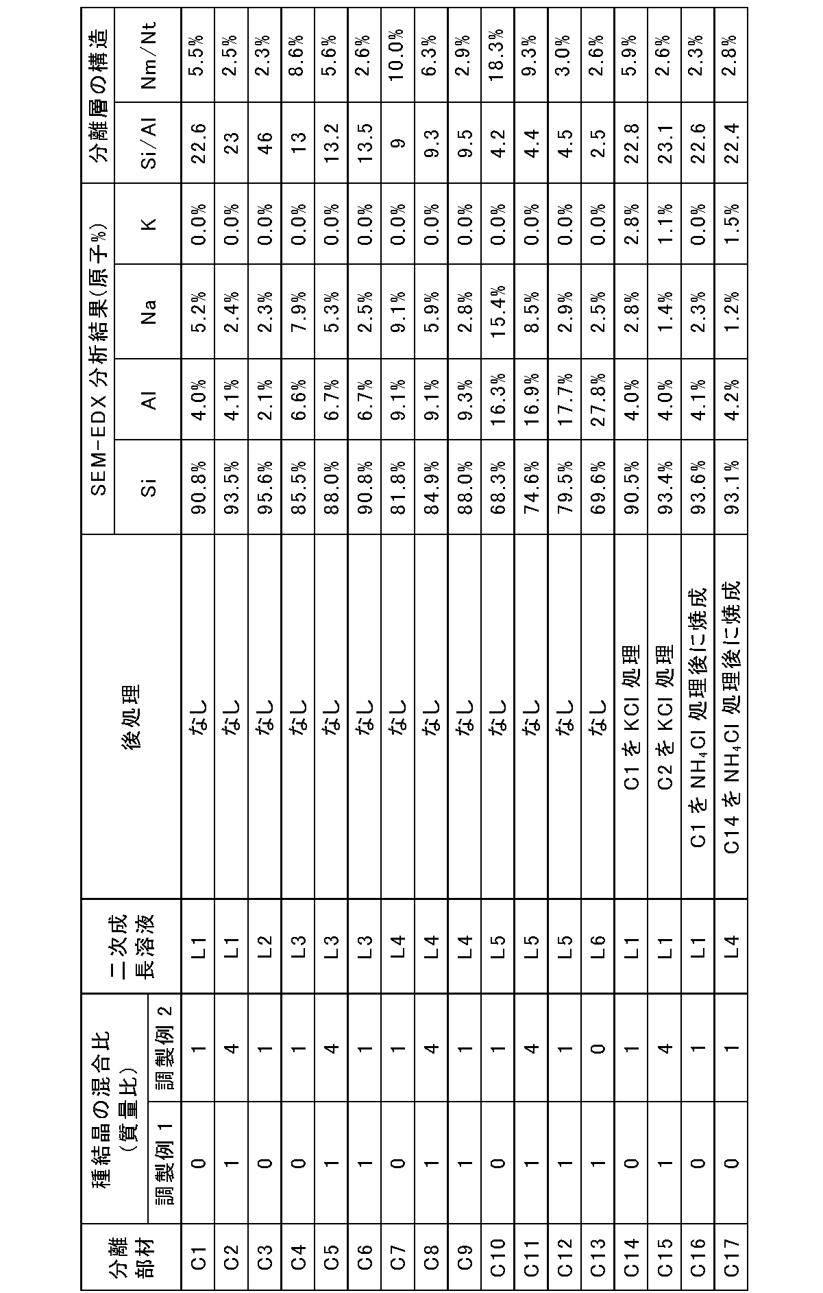
- a seed crystal dispersion liquid was prepared in the same manner as the seed crystal dispersion liquid of the separation member A1, with the mass ratio of the seed crystals shown in Tables 1 and 2.
- the seed crystal content in the dispersion was set to 0.05% by mass (the same applies to the production of the separation member below).
- Separating members A2, A3, C1, and C2 were produced under the same conditions as those for producing separating member A1, except that the obtained dispersion was used as a seed crystal dispersion.
- a seed crystal dispersion liquid was prepared in the same manner as the seed crystal dispersion liquid of the separation member A1, with the mass ratio of the seed crystals shown in Tables 1 and 2.
- seed crystals were applied to the porous support by the same dipping method as that used in the preparation of the separation member A1.
- separation members A4, A5, A6, A7, and C3 were produced in the same manner as the separation member A1 except that the secondary growth solution (L2) having the following composition was used.
- a seed crystal dispersion liquid was prepared in the same manner as the seed crystal dispersion liquid of the separation member A1, with the mass ratio of the seed crystals shown in Tables 1 and 2. Using the dispersion liquid, seed crystals were applied to the porous support by the same dipping method as that used in the preparation of the separation member A1. Thereafter, separation members A8, A9, C4, C5, and C6 were produced in the same manner as the separation member A1 except that the secondary growth solution (L3) having the following composition was used. In other words, these separation member manufacturing methods differ only in the seed crystal dispersion.
- a seed crystal dispersion liquid was prepared in the same manner as the seed crystal dispersion liquid of the separation member A1, with the mass ratio of the seed crystals shown in Tables 1 and 2.
- seed crystals were applied to the porous support by the same dipping method as that used in the preparation of the separation member A1.
- separation members A10, A11, C7, C8, and C9 were produced in the same manner as the separation member A1, except that the secondary growth solution (L4) having the following composition was used. In other words, these separation member manufacturing methods differ only in the seed crystal dispersion.
- a seed crystal dispersion liquid was prepared in the same manner as the seed crystal dispersion liquid of the separation member A1, with the mass ratio of the seed crystals shown in Tables 1 and 2.
- seed crystals were applied to the porous support by the same dipping method as that used in the preparation of the separation member A1.
- separation members A12, A13, C10, C11, and C12 were produced in the same manner as the separation member A1, except that the secondary growth solution (L5) having the following composition was used. In other words, these separation member manufacturing methods differ only in the seed crystal dispersion.
- Separating members A14, A15, A16, C14, C15 First, separation members A1, A2, A3, C1, and C2 were produced. Next, ion exchange between Na and K was performed by immersing the separation members in a 0.01 M potassium chloride aqueous solution at room temperature for 24 hours (KCl treatment). The resulting separation member was then dried overnight at 60°C. Separation members A14, A15, A16, C14 and C15 were thus obtained. Tables 1 and 2 show the relationship between the separation member before KCl treatment and the resulting separation member.
- the separation member obtained as described above was evaluated in the same manner as the separation member A1. However, the separation member C13 could not be evaluated because the supply pressure could not be increased to the conditions of the separation test 1. In general, if the Si/Al molar ratio in the separation layer is too low, the heat resistance of the zeolite layer may decrease, and the separation layer may have collapsed during firing.
- the zeolite layers of the separation members A1 to A20 and C1 to C17 had a CHA structure.
- the peak intensity ratios of the X-ray diffraction peaks (9.6°/20.8° and 17.9°/20.8° ).
- the intensity ratio of 9.6°/20.8° is 1.5 or more and less than 4
- the intensity ratio of 17.9°/20.8° is 0.5°. It was 2 or more and less than 0.5.
- the thickness of the separating layer was about 5 ⁇ m in all separating members.
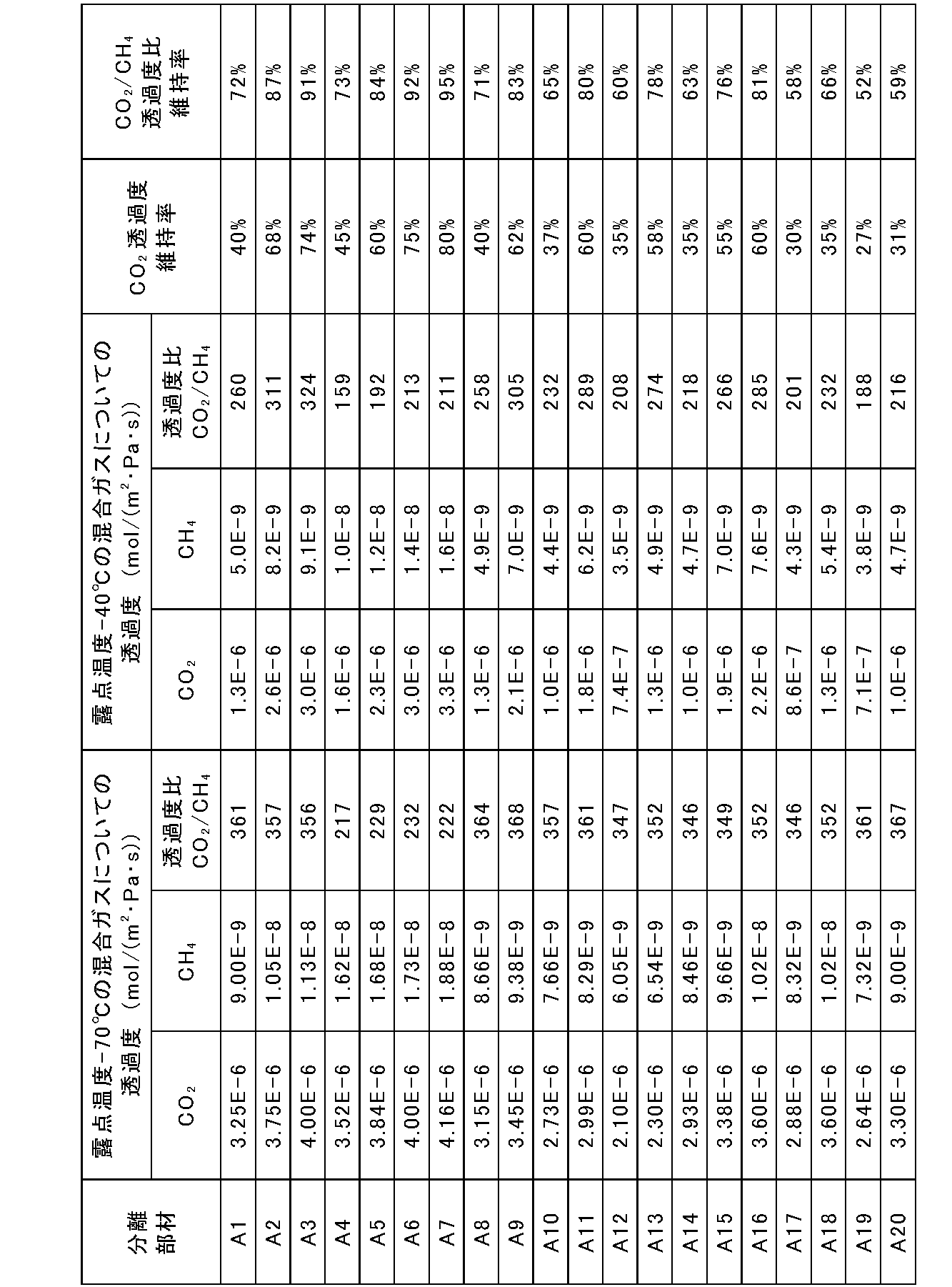
- Some of the manufacturing conditions are shown in Tables 1 and 2, and some of the evaluation results are shown in Tables 3 and 4.
- “En” (n is a natural number) in Tables 3 and 4 means “10 ⁇ n ”.
- the "CO 2 permeability retention rate” and the “CO 2 /CH 4 permeability ratio retention rate” in Tables 3 and 4 are obtained by the following equations, respectively.
- CO 2 permeability retention rate (%) 100 ⁇ (CO 2 permeability for mixed gas with dew point temperature of ⁇ 40° C.)/(CO 2 permeability for mixed gas with dew point temperature of ⁇ 70° C.)
- CO 2 / CH 4 permeability ratio maintenance rate (%) 100 ⁇ (CO 2 / CH 4 permeability ratio for mixed gas with dew point temperature of -40 ° C.) / (for mixed gas with dew point temperature of -70 ° C. CO2 / CH4 permeability ratio)
- the separation member of this embodiment can be used to separate CO2 from mixed gases. Therefore, it is preferable that the CO 2 permeability and the CO 2 /CH 4 permeability ratio are large.
- FIGS. 3 and 4 show CO 2 /CH 4 permeability ratio retention.
- FIG. 4 shows CO 2 permeability retention.
- FIGS. 5 and 6 show the separation performance maintenance ratios of all the separation members in Tables 3 and 4.
- FIG. 5 shows CO 2 /CH 4 permeability ratio retention.
- FIG. 6 shows the CO2 permeability retention.
- the CO 2 permeability and the CO 2 /CH 4 permeability ratio of the mixed gas containing a large amount of water vapor Compared to those of the mixed gas at a temperature of -70°C), it decreased greatly. It is considered that this is because the content of the metal element (M) in the separation layer is high (because the value of Nm/Nt is large).
- the metal element (M) reduces the pore volume of the zeolite crystal layer included in the separation layer. Furthermore, pore blockage is caused by water vapor adsorption due to electrostatic interactions between the cations of the metal element (M) and water vapor. As a result, it is believed that the diffusivity of CO2 in the pores was significantly reduced.
- CH4 permeates grain boundaries that are larger than the pores of CHA-type zeolite, it is less susceptible to the permeation inhibition effect of water vapor than CO2 .
- the dense zeolite crystal layer since there are few grain boundaries that become defects in the zeolite crystal layer, the effect of the grain boundaries on the separation performance is small.
- the CO2 / CH4 permeability ratio decreased significantly with increasing water vapor in the gas mixture. This is believed to be due to the fact that the decrease in permeability due to water vapor is greater for CO2 than for CH4 .
- Separation members A1 to A13 had significantly higher CO 2 permeability maintenance rate and permeability ratio maintenance rate than separation members C1 to C12. This is probably because the content of the metal element (M) in the separation layer is lower than that of the separation members C1 to C12 (because the value of Nm/Nt is small), so the deterioration of the above characteristics can be suppressed.
- Separation members C14, C15 and separation members A14 to A16 are all separation members in which part of Na ions are ion-exchanged to K ions. Comparing these separation members, the separation members A14 to A16 having a lower content of the metal element (M) had a higher separation performance for the mixed gas containing a large amount of water vapor.
- Separation members C16 and C17 and separation members A17 to A20 are all separation members in which part of Na ions are ion-exchanged to H ions. Comparing these, the separation members A17 to A20 having a lower content of the metal element (M) had a higher separation performance for the mixed gas containing a large amount of water vapor.
- the value of Nm/Nt is preferably 2.0% or less (0.020 or less), It is more preferably 1.8% or less, still more preferably 1.4% or less (eg, 1.0% or less), and particularly preferably 0.6% or less (eg, 0.4% or less).
- the method is not limited, when the value of Nm/Nt exceeds 2.0%, post-treatment such as ion exchange of cations of the metal element (M) to H ions is performed as in the separation members A17 to A20. It is possible to reduce the value of Nm/Nt to 2.0 or less. However, as shown in FIGS. 5 and 6, when the values of Nm/Nt are the same, there is a general tendency that characteristics are higher when ion exchange is not performed.
- the metal element (M) in the separation layer alkaline earth metals or alkali metals are preferred, and Na and K are particularly preferred.
- the Si/Al molar ratio in the separation layer is not particularly limited, but if it is too low, the heat resistance of the separation layer tends to be weak. Therefore, the Si/Al molar ratio is usually 3 or more, preferably 5 or more. Also, when the Si/Al molar ratio is very high or infinite, a large amount of structure-directing agent is required during the production of the separation member. Therefore, the Si/Al molar ratio is preferably less than 50, more preferably less than 30 (for example less than 20), particularly preferably less than 14. These lower limits and upper limits can be combined arbitrarily.
Landscapes
- Chemical & Material Sciences (AREA)
- Engineering & Computer Science (AREA)
- Chemical Kinetics & Catalysis (AREA)
- Ceramic Engineering (AREA)
- Inorganic Chemistry (AREA)
- Analytical Chemistry (AREA)
- Structural Engineering (AREA)
- Organic Chemistry (AREA)
- Materials Engineering (AREA)
- Oil, Petroleum & Natural Gas (AREA)
- General Chemical & Material Sciences (AREA)
- Dispersion Chemistry (AREA)
- Geology (AREA)
- Life Sciences & Earth Sciences (AREA)
- Manufacturing & Machinery (AREA)
- Crystallography & Structural Chemistry (AREA)
- Separation Using Semi-Permeable Membranes (AREA)
- Silicates, Zeolites, And Molecular Sieves (AREA)
Abstract
Description
本発明の新規な特徴を添付の請求の範囲に記述するが、本発明は、構成および内容の両方に関し、本発明の他の目的および特徴と併せ、図面を照合した以下の詳細な説明によりさらによく理解されるであろう。
本実施形態に係る分離部材は、多孔質支持体と、多孔質支持体上に配置された分離層とを含む。当該分離部材および当該分離層をそれぞれ、以下では、「分離部材(S)」および「分離層(SL)」と称する場合がある。分離層(SL)は、アルミノケイ酸塩を含むゼオライト層を含む。分離層(SL)に含まれるアルカリ金属元素およびアルカリ土類金属元素(共に第3周期以降)の合計の原子数Nmは、分離層(SL)に含まれる四配位の原子の原子数Ntの2.0%以下である。すなわち、原子数Nmと原子数Ntとの比であるNm/Ntは、Nm/Nt≦2.0%(0.020)を満たす。以下では、分離層(SL)に含まれる第3周期以降のアルカリ金属元素および第3周期以降のアルカリ土類金属元素をまとめて、「金属元素(M)」と称する場合がある。別の観点では、金属元素(M)は、LiおよびBe以外のアルカリ金属元素およびアルカリ土類金属元素である。なお、Nm/Ntは、モル比と考えることも可能である。
(1)原子数Nmは、原子数Ntの2.0%以下である。この場合、原子数Nmは、原子数Ntの0%以上、0.2%以上、または0.4%以上であってもよい。
(2)分離層(SL)に含まれるSiの原子数は、分離層(SL)に含まれるAlの原子数の3倍以上で15倍未満(好ましくは5倍以上で14倍未満)である。
(1)(2θ=9.6°付近のピークの強度)/(2θ=20.8°付近のピークの強度)で求められる強度比が、1.5以上で4未満である。当該強度比は、1.5以上で3未満、または1.5以上で2未満であってもよい。
(2)(2θ=17.9°付近のピークの強度)/(2θ=20.8°付近のピークの強度)で求められる強度比が、0.2以上で0.5未満である。当該強度比は、0.3以上で0.5未満、または0.4以上で0.5未満であってもよい。
ここで、「2θ=9.6°付近のピーク」とは、基材に由来しないピークであって9.6°±0.6°の範囲に存在するピークのうち最大のものを指す。「2θ=17.9°付近のピーク」とは、基材に由来しないピークであって17.9°±0.6°の範囲に存在するピークのうち最大のものを指す。「2θ=20.8°付近のピーク」とは、基材に由来しないピークであって20.8°±0.6°の範囲に存在するピークのうち最大のものを指す。
本開示に係る分離部材(SL)の製造方法の一例について以下に説明する。ただし、分離部材(SL)は、以下で説明する製造方法以外の方法で製造してもよい。
まず、多孔質支持体(以下では、「支持体」と称する場合がある)を準備する。多孔質支持体には、ゼオライトを用いた分離部材で利用されている多孔質支持体を用いることができる。例えば、上述した多孔質支持体を用いてもよい。
種結晶層としては、形成するゼオライト層の構造と同じ構造を有する種結晶層を形成する。種結晶層は、例えば、後述するゼオライト層で用いられる水熱合成法と同様の方法によって形成してもよい。例えば、有機構造規定剤およびシリカ源として、後述するゼオライト層の形成で用いられるものを用いてもよい。
次に、多孔質支持体上に種結晶層を形成する。多孔質支持体上に種結晶層を形成する方法に特に限定はない。例えば、水などの溶媒に種結晶を分散させて分散液を調製し、その分散液に支持体を浸漬することによって種結晶層を支持体に付着させてもよい(ディップ法)。あるいは、水などの溶媒と種結晶とを混合してスラリーを調製し、そのスラリーを支持体の表面に塗布することによって種結晶層を形成してもよい。種結晶の塗布量は、例えば、多孔質支持体の質量の1×10⁻⁴~1×10⁻³%としてもよい。種結晶を塗布した支持体は、支持体と種結晶との接着性を高めるために、450℃~700℃の範囲の温度で熱処理してもよい。
ゼオライト層は、シリカ種結晶が表面に配置された多孔質支持体上に形成される。具体的には、ゼオライト層を合成するための原料の組成物(ゲル)に多孔質支持体を浸漬した状態で、ゼオライト層を水熱合成する。
有機構造規定剤/SiO2=0.05~0.5、
塩基/SiO2=0.02~0.3、
H2O/SiO2=100~300、
SiO2/Al2O3=10~100
本開示に係る分離方法は、本開示に係る分離部材(S)を用いて混合ガスを分離する分離工程を含む。分離工程は、本開示に係る分離部材(S)を用いることを除いて特に限定はなく、公知の分離工程と同様の方法で行ってもよい。
(1)混合ガスは二酸化炭素ガスを含む。分離工程において、混合ガスから二酸化炭素ガスを分離する。すなわち、分離部材(S)を透過した二酸化炭素ガスが分離される。
(2)混合ガスは水蒸気を含む。分離工程において、混合ガスから水蒸気を分離する。すなわち、分離部材(S)を透過した水蒸気が分離される。
(3)混合ガスは、炭素数が1以上の炭化水素ガス、水素ガス、窒素ガス、および硫化水素ガスからなる群より選択される少なくとも1つのガスをさらに含む。一例では、これらのうちメタンガス、エタンガス、エチレンガス、プロパンガス、プロピレンガス、水素ガス、窒素ガス、硫化水素等を、分離部材(S)によって、CO2と共に分離することが可能である。炭素数が1以上の炭化水素ガスの例には、メタンガス、エタンガス、エチレンガス、プロパンガス、プロピレンガスなどが含まれる。
調製例1では、CHA型構造を有するシリカ種結晶を以下の方法で作製した。まず、ポリテトラフルオロエチレン製(以下では、「PTFE」と称する場合がある)の容器にTMAdaOH(「有機構造規定剤」と称する場合がある。)とコロイダルシリカ(シリカ源)とを混合して混合物とし、その混合物にフッ化水素酸を加えた。その後、混合物を撹拌しながら加熱することによって、水を完全に除去して固体を得た。
調製例2では、「Separation and Purification Technology 199(2018),298-303」に記載の方法に沿ってアルミノケイ酸塩含有のCHA型構造を有するゼオライト種結晶を作製した。具体的には、まず、オートクレーブ内のPTFE製内筒にTMAdaOH、水酸化ナトリウム、FAU型ゼオライト(東ソー株式会社製、品番:HSZ-360、HSZ-390)およびイオン交換水を加えた。HSZ-360の化学組成は、SiO2/Al2O3=14(モル比)である。HSZ-390の化学組成は、SiO2/Al2O3=400(モル比)である。ゼオライトは、シリカ源およびアルミニウム源として機能する。材料のモル比は、SiO2:TMAdaOH:NaOH:H2O:Al2O3=1:0.2:0.2:7.0:20とした。その後、オートクレーブを密閉し、160℃で40時間にわたって水熱合成を行った。その後、オートクレーブ内の内部を冷却した。そして、内筒内のゲルをイオン交換水で洗浄し、100℃で乾燥させた。このようにして、アルミノケイ酸塩を含みCHA型構造を有するゼオライト種結晶を得た。
調製例1で得た種結晶と調製例2で得た種結晶とを1:1の質量比で混合し、得られた混合物にイオン交換水を加えて、種結晶の分散液を作製した。分散液中の種結晶の含有量は、0.05質量%とした。この分散液を用いて、ディップ法によってアルミナからなる多孔質支持体(円筒状)の外面に種結晶を塗布した。円筒状の多孔質支持体には、長さが1m、厚さが2mm、内径が12mm、表面粗さ(上述した算術平均粗さRa)が1.2~2.0μmのものを用いた。
分離部材A1を用いて、CO2とCH4との混合ガスについてのガス透過試験を行った。そして、分離部材A1を透過したガスの透過度を測定した。混合ガスとしては、大気圧下における露点温度が-40℃のガス、および、大気圧下における露点温度が-70°のガスを用いた。-40°の露点温度ガスは、-70°の露点温度ガスを加湿することによって調整した。試験前の前処理として、分離層にCO2を10L/minで供給しながら、120℃で1時間にわたって乾燥させる処理を行った。試験条件は以下の通りである。
混合ガスの構成比:CO2/CH4:50mol%/50mol%
混合ガスの供給圧力:0.2MPaA(パスカル絶対圧)
混合ガスの透過側の圧力:0.1MPaA(パスカル絶対圧)
混合ガスの供給流量:40L/min
試験温度:40℃
混合ガスの大気圧露点温度:-40°、-70°
次に、分離部材A1を切断し、分離層の断面をFE-SEM(電界放出形走査電子顕微鏡:株式会社日立ハイテク製、型式:S-5500)を用いて断面を撮影することによって層厚を測定した。FE-SEMの画像を図1に示す。分離部材A1は、多孔質支持体11と分離層12とを含む。分離層12から3箇所(長手方向の両端および中央付近からそれぞれ1箇所ずつ)選択して、その3箇所の分離層12の厚さを測定した。このとき、図1に示すように、多孔質支持体11の表面から分離層12の表面までの距離を、分離層12の厚さとした。そして、3箇所の厚さの平均値を、分離層12の層厚とした。分離部材A1の分離層12の層厚は約5μmであった。
X線源:CuKα線(出力:40kV、40mA)
走査軸:θ/2θ
走査範囲(2θ):5.0-50.0°
測定モード:Continuos Scanning
発散スリット:2/3°
発散縦制限スリット:10mm
散乱スリット:開放
受光スリット:開放
種結晶の比率を表1および表2に示す質量比として、分離部材A1の種結晶の分散液と同様に、種結晶の分散液を作製した。分散液における種結晶の含有量は、0.05質量%とした(以下の分離部材の製造においても同様である)。得られた分散液を種結晶の分散液として用いることを除いて、分離部材A1の作製と同様の条件で分離部材A2、A3、C1、およびC2を作製した。
種結晶の比率を表1および表2に示す質量比として、分離部材A1の種結晶の分散液と同様に、種結晶の分散液を作製した。その分散液を用いて分離部材A1の作製時に用いたディップ法と同様のディップ法で多孔質支持体に種結晶を塗布した。その後、以下の組成の二次成長溶液(L2)を用いた以外は分離部材A1の作製と同様の方法で分離部材A4、A5、A6、A7、およびC3を作製した。すなわち、これらの分離部材の製造方法は、種結晶の分散液のみが異なる。二次成長溶液(L2)のモル比は、TMAdaOH/SiO2=0.1、NaOH/SiO2=0.167、H2O/SiO2=150、SiO2/Al2O3=100とした。
種結晶の比率を表1および表2に示す質量比として、分離部材A1の種結晶の分散液と同様に、種結晶の分散液を作製した。その分散液を用いて分離部材A1の作製時に用いたディップ法と同様のディップ法で多孔質支持体に種結晶を塗布した。その後、以下の組成の二次成長溶液(L3)を用いた以外は分離部材A1の作製と同様の方法で分離部材A8、A9、C4、C5、およびC6を作製した。すなわち、これらの分離部材の製造方法は、種結晶の分散液のみが異なる。二次成長溶液(L3)のモル比は、TMAdaOH/SiO2=0.1、NaOH/SiO2=0.167、H2O/SiO2=150、SiO2/Al2O3=30とした。
種結晶の比率を表1および表2に示す質量比として、分離部材A1の種結晶の分散液と同様に、種結晶の分散液を作製した。その分散液を用いて分離部材A1の作製時に用いたディップ法と同様のディップ法で多孔質支持体に種結晶を塗布した。その後、以下の組成の二次成長溶液(L4)を用いた以外は分離部材A1の作製と同様の方法で分離部材A10、A11、C7、C8、C9を作製した。すなわち、これらの分離部材の製造方法は、種結晶の分散液のみが異なる。二次成長溶液(L4)のモル比は、TMAdaOH/SiO2=0.1、NaOH/SiO2=0.167、H2O/SiO2=150、SiO2/Al2O3=20とした。
種結晶の比率を表1および表2に示す質量比として、分離部材A1の種結晶の分散液と同様に、種結晶の分散液を作製した。その分散液を用いて分離部材A1の作製時に用いたディップ法と同様のディップ法で多孔質支持体に種結晶を塗布した。その後、以下の組成の二次成長溶液(L5)を用いた以外は分離部材A1の作製と同様の方法で分離部材A12、A13、C10、C11、およびC12を作製した。すなわち、これらの分離部材の製造方法は、種結晶の分散液のみが異なる。二次成長溶液(L5)のモル比は、TMAdaOH/SiO2=0.1、NaOH/SiO2=0.167、H2O/SiO2=150、SiO2/Al2O3=10とした。
種結晶の比率を表2に示す質量比として、分離部材A1の種結晶の分散液と同様に、種結晶の分散液を作製した。その分散液を用いて分離部材A1の作製時に用いたディップ法と同様のディップ法で多孔質支持体に種結晶を塗布した。その後、以下の組成の二次成長溶液(L6)を用いた以外は分離部材A1の作製と同様の方法で分離部材C13を作製した。二次成長溶液(L6)のモル比は、TMAdaOH/SiO2=0.1、NaOH/SiO2=0.167、H2O/SiO2=150、SiO2/Al2O3=5とした。
まず、分離部材A1、A2、A3、C1、およびC2を作製した。次に、0.01M塩化カリウム水溶液に室温でそれらの分離部材を24時間浸漬することによって、NaとKとのイオン交換を行った(KCl処理)。その後、得られた分離部材を60℃で一晩乾燥させた。このようにして分離部材A14、A15、A16、C14、およびC15を得た。KCl処理前の分離部材と、得られた分離部材との対応関係については表1および表2に示す。
まず、分離部材C2、A3、C15、A15、C1、およびC14を作製した。次に、0.01M塩化アンモニウム水溶液に室温でそれらの分離部材を24時間浸漬することによって、アルカリ金属イオン(NaおよびK)とHイオンとのイオン交換を行った(NH4Cl処理)。その後、得られた分離部材を60℃で一晩乾燥させ、さらに、電気炉で10時間、350℃で焼成した。このようにして、分離部材A17、A18、A19、A20、C16、およびC17を得た。NH4Cl処理前の分離部材と、得られた分離部材との対応関係については表1および表2に示す。
CO2透過度維持率(%)=100×(露点温度が-40℃の混合ガスについてのCO2透過度)/(露点温度が-70℃の混合ガスについてのCO2透過度)
CO2/CH4透過度比維持率(%)=100×(露点温度が-40℃の混合ガスについてのCO2/CH4透過度比)/(露点温度が-70℃の混合ガスについてのCO2/CH4透過度比)


本発明を現時点での好ましい実施態様に関して説明したが、そのような開示を限定的に解釈してはならない。種々の変形および改変は、上記開示を読むことによって本発明に属する技術分野における当業者には間違いなく明らかになるであろう。したがって、添付の請求の範囲は、本発明の真の精神および範囲から逸脱することなく、すべての変形および改変を包含する、と解釈されるべきものである。
Claims (9)
- 多孔質支持体と、前記多孔質支持体上に配置された分離層とを含む分離部材であって、
前記分離層は、アルミノケイ酸塩を含むゼオライト層を含み、
前記分離層に含まれる第3周期以降のアルカリ金属元素およびアルカリ土類金属元素の合計の原子数Nmは、前記分離層に含まれる四配位の原子の原子数Ntの2.0%以下である、分離部材。 - 前記分離層に含まれるSiの原子数は、前記分離層に含まれるAlの原子数の5倍以上で14倍未満である、請求項1に記載の分離部材。
- 前記ゼオライト層を構成するゼオライトの構造は、CHA型構造である、請求項1または2に記載の分離部材。
- 前記分離層は、前記多孔質支持体と前記ゼオライト層との間に配置された種結晶をさらに含み、
前記種結晶は、シリカ種結晶を含む、請求項1~3のいずれか1項に記載の分離部材。 - 前記種結晶は、アルミノケイ酸塩を含むゼオライト種結晶をさらに含む、請求項4に記載の分離部材。
- 前記シリカ種結晶の構造は、CHA型構造である、請求項4または5に記載の分離部材。
- 分離部材を用いて混合ガスを分離する分離工程を含み、
前記分離部材は、請求項1~6のいずれか1項に記載の分離部材である、分離方法。 - 前記混合ガスは二酸化炭素ガスを含み、
前記分離工程において、前記混合ガスから前記二酸化炭素ガスを分離する、請求項7に記載の分離方法。 - 前記混合ガスの露点温度は-70℃以上である、請求項7または8に記載の分離方法。
Priority Applications (2)
| Application Number | Priority Date | Filing Date | Title |
|---|---|---|---|
| PCT/JP2021/043443 WO2023095300A1 (ja) | 2021-11-26 | 2021-11-26 | 分離部材および分離方法 |
| EP21965671.7A EP4438164A4 (en) | 2021-11-26 | 2021-11-26 | SEPARATION ELEMENT AND METHOD |
Applications Claiming Priority (1)
| Application Number | Priority Date | Filing Date | Title |
|---|---|---|---|
| PCT/JP2021/043443 WO2023095300A1 (ja) | 2021-11-26 | 2021-11-26 | 分離部材および分離方法 |
Publications (1)
| Publication Number | Publication Date |
|---|---|
| WO2023095300A1 true WO2023095300A1 (ja) | 2023-06-01 |
Family
ID=86539251
Family Applications (1)
| Application Number | Title | Priority Date | Filing Date |
|---|---|---|---|
| PCT/JP2021/043443 Ceased WO2023095300A1 (ja) | 2021-11-26 | 2021-11-26 | 分離部材および分離方法 |
Country Status (2)
| Country | Link |
|---|---|
| EP (1) | EP4438164A4 (ja) |
| WO (1) | WO2023095300A1 (ja) |
Citations (8)
| Publication number | Priority date | Publication date | Assignee | Title |
|---|---|---|---|---|
| JP2012066242A (ja) * | 2010-08-26 | 2012-04-05 | Mitsubishi Chemicals Corp | ガス分離用ゼオライト膜複合体 |
| JP2013226534A (ja) * | 2012-03-30 | 2013-11-07 | Mitsubishi Chemicals Corp | ゼオライト膜複合体 |
| JP2013226533A (ja) * | 2012-03-30 | 2013-11-07 | Mitsubishi Chemicals Corp | ゼオライト膜複合体 |
| JP2013226535A (ja) * | 2012-03-30 | 2013-11-07 | Mitsubishi Chemicals Corp | ゼオライト膜複合体 |
| WO2017081841A1 (ja) | 2015-11-09 | 2017-05-18 | 公益財団法人地球環境産業技術研究機構 | 結晶性シリカ膜複合体およびその製造方法、並びに流体分離方法 |
| WO2017142056A1 (ja) | 2016-02-19 | 2017-08-24 | 日立造船株式会社 | ゼオライト分離膜およびその製造方法 |
| JP2019155219A (ja) * | 2018-03-07 | 2019-09-19 | 日立造船株式会社 | Cha型チタノシリケート分離膜およびその製造方法、並びにガス分離方法 |
| US20200298187A1 (en) * | 2019-03-18 | 2020-09-24 | Korea University Research And Business Foundation | Method of preparing heterogeneous zeolite membranes |
Family Cites Families (6)
| Publication number | Priority date | Publication date | Assignee | Title |
|---|---|---|---|---|
| JP2014198308A (ja) * | 2013-03-29 | 2014-10-23 | 日本碍子株式会社 | セラミック分離フィルタ及び脱水方法 |
| EP3132842A4 (en) * | 2014-04-18 | 2017-04-05 | Mitsubishi Chemical Corporation | (porous support)-(zeolite film) complex, and method for producing (porous support)-(zeolite film) complex |
| EP3411148A1 (en) * | 2016-02-01 | 2018-12-12 | Umicore Ag & Co. Kg | Hydrothermally stable iron containing aei zeolite scr catalyst |
| JP6320658B1 (ja) * | 2016-10-25 | 2018-05-09 | 日揮触媒化成株式会社 | 基材コート用チャバザイト型ゼオライト |
| JP7167462B2 (ja) * | 2017-03-27 | 2022-11-09 | 三菱ケミカル株式会社 | アルカリ性含水有機化合物の水分離方法 |
| JP6986613B1 (ja) * | 2020-11-04 | 2021-12-22 | 日立造船株式会社 | 分離部材および分離方法 |
-
2021
- 2021-11-26 EP EP21965671.7A patent/EP4438164A4/en active Pending
- 2021-11-26 WO PCT/JP2021/043443 patent/WO2023095300A1/ja not_active Ceased
Patent Citations (8)
| Publication number | Priority date | Publication date | Assignee | Title |
|---|---|---|---|---|
| JP2012066242A (ja) * | 2010-08-26 | 2012-04-05 | Mitsubishi Chemicals Corp | ガス分離用ゼオライト膜複合体 |
| JP2013226534A (ja) * | 2012-03-30 | 2013-11-07 | Mitsubishi Chemicals Corp | ゼオライト膜複合体 |
| JP2013226533A (ja) * | 2012-03-30 | 2013-11-07 | Mitsubishi Chemicals Corp | ゼオライト膜複合体 |
| JP2013226535A (ja) * | 2012-03-30 | 2013-11-07 | Mitsubishi Chemicals Corp | ゼオライト膜複合体 |
| WO2017081841A1 (ja) | 2015-11-09 | 2017-05-18 | 公益財団法人地球環境産業技術研究機構 | 結晶性シリカ膜複合体およびその製造方法、並びに流体分離方法 |
| WO2017142056A1 (ja) | 2016-02-19 | 2017-08-24 | 日立造船株式会社 | ゼオライト分離膜およびその製造方法 |
| JP2019155219A (ja) * | 2018-03-07 | 2019-09-19 | 日立造船株式会社 | Cha型チタノシリケート分離膜およびその製造方法、並びにガス分離方法 |
| US20200298187A1 (en) * | 2019-03-18 | 2020-09-24 | Korea University Research And Business Foundation | Method of preparing heterogeneous zeolite membranes |
Non-Patent Citations (3)
| Title |
|---|
| J. MATER. CHEM. A, vol. 2, 2014, pages 13083 - 13092 |
| See also references of EP4438164A4 |
| SEPARATION AND PURIFICATION TECHNOLOGY, vol. 199, 2018, pages 298 - 303 |
Also Published As
| Publication number | Publication date |
|---|---|
| EP4438164A4 (en) | 2025-10-08 |
| EP4438164A1 (en) | 2024-10-02 |
Similar Documents
| Publication | Publication Date | Title |
|---|---|---|
| JP6986613B1 (ja) | 分離部材および分離方法 | |
| JP7060042B2 (ja) | 多孔質支持体-ゼオライト膜複合体及び多孔質支持体-ゼオライト膜複合体の製造方法 | |
| JP7163951B2 (ja) | ゼオライト膜複合体 | |
| JP6107809B2 (ja) | 多孔質支持体―ゼオライト膜複合体 | |
| US11666867B2 (en) | Zeolite separation membrane and production method therefor | |
| JP6446378B2 (ja) | 多孔性基板上にゼオライトおよび/またはゼオライト様結晶の結晶膜を製造するための方法 | |
| JP6107000B2 (ja) | ゼオライト膜複合体 | |
| JP6167489B2 (ja) | ゼオライト膜複合体 | |
| JP6163719B2 (ja) | 硫化水素の分離方法 | |
| WO2017221761A1 (ja) | Mfi型ゼオライト(シリカライト)を用いた分離膜の製造方法 | |
| JP4728122B2 (ja) | ガス分離体、及びその製造方法 | |
| JP2004344755A (ja) | ゼオライト複合薄膜 | |
| WO2023095300A1 (ja) | 分離部材および分離方法 | |
| JP6436207B2 (ja) | 気体の分離または濃縮方法、および高酸素濃度混合気体の製造方法 | |
| JP6476021B2 (ja) | ゼオライト膜およびゼオライト粉末の製造方法 | |
| WO2025078349A1 (en) | Methods for preparing a heu-type separation membrane, separation membrane thereof, and use of the separation membrane thereof as gas separator | |
| JP2026049553A (ja) | 無機分離膜の製造方法 | |
| Palomino Roca | Synthesis and Characterization of FAU membranes |
Legal Events
| Date | Code | Title | Description |
|---|---|---|---|
| 121 | Ep: the epo has been informed by wipo that ep was designated in this application |
Ref document number: 21965671 Country of ref document: EP Kind code of ref document: A1 |
|
| WWE | Wipo information: entry into national phase |
Ref document number: 202447036776 Country of ref document: IN |
|
| WWE | Wipo information: entry into national phase |
Ref document number: 2401003194 Country of ref document: TH |
|
| WWE | Wipo information: entry into national phase |
Ref document number: 2021965671 Country of ref document: EP |
|
| NENP | Non-entry into the national phase |
Ref country code: DE |
|
| ENP | Entry into the national phase |
Ref document number: 2021965671 Country of ref document: EP Effective date: 20240626 |
|
| NENP | Non-entry into the national phase |
Ref country code: JP |