WO2023095485A1 - 開閉器 - Google Patents
開閉器 Download PDFInfo
- Publication number
- WO2023095485A1 WO2023095485A1 PCT/JP2022/038412 JP2022038412W WO2023095485A1 WO 2023095485 A1 WO2023095485 A1 WO 2023095485A1 JP 2022038412 W JP2022038412 W JP 2022038412W WO 2023095485 A1 WO2023095485 A1 WO 2023095485A1
- Authority
- WO
- WIPO (PCT)
- Prior art keywords
- movable contact
- contact
- auxiliary yoke
- axis direction
- center
- Prior art date
- Legal status (The legal status is an assumption and is not a legal conclusion. Google has not performed a legal analysis and makes no representation as to the accuracy of the status listed.)
- Ceased
Links
Images











Classifications
-
- H—ELECTRICITY
- H01—ELECTRIC ELEMENTS
- H01H—ELECTRIC SWITCHES; RELAYS; SELECTORS; EMERGENCY PROTECTIVE DEVICES
- H01H50/00—Details of electromagnetic relays
- H01H50/16—Magnetic circuit arrangements
- H01H50/36—Stationary parts of magnetic circuit, e.g. yoke
-
- H—ELECTRICITY
- H01—ELECTRIC ELEMENTS
- H01H—ELECTRIC SWITCHES; RELAYS; SELECTORS; EMERGENCY PROTECTIVE DEVICES
- H01H9/00—Details of switching devices, not covered by groups H01H1/00 - H01H7/00
- H01H9/30—Means for extinguishing or preventing arc between current-carrying parts
- H01H9/44—Means for extinguishing or preventing arc between current-carrying parts using blow-out magnet
- H01H9/443—Means for extinguishing or preventing arc between current-carrying parts using blow-out magnet using permanent magnets
-
- H—ELECTRICITY
- H01—ELECTRIC ELEMENTS
- H01H—ELECTRIC SWITCHES; RELAYS; SELECTORS; EMERGENCY PROTECTIVE DEVICES
- H01H50/00—Details of electromagnetic relays
- H01H50/54—Contact arrangements
-
- H—ELECTRICITY
- H01—ELECTRIC ELEMENTS
- H01H—ELECTRIC SWITCHES; RELAYS; SELECTORS; EMERGENCY PROTECTIVE DEVICES
- H01H50/00—Details of electromagnetic relays
- H01H50/54—Contact arrangements
- H01H50/546—Contact arrangements for contactors having bridging contacts
-
- H—ELECTRICITY
- H01—ELECTRIC ELEMENTS
- H01H—ELECTRIC SWITCHES; RELAYS; SELECTORS; EMERGENCY PROTECTIVE DEVICES
- H01H50/00—Details of electromagnetic relays
- H01H50/02—Bases; Casings; Covers
- H01H50/04—Mounting complete relay or separate parts of relay on a base or inside a case
- H01H50/041—Details concerning assembly of relays
- H01H50/045—Details particular to contactors
-
- H—ELECTRICITY
- H01—ELECTRIC ELEMENTS
- H01H—ELECTRIC SWITCHES; RELAYS; SELECTORS; EMERGENCY PROTECTIVE DEVICES
- H01H50/00—Details of electromagnetic relays
- H01H50/16—Magnetic circuit arrangements
- H01H50/163—Details concerning air-gaps, e.g. anti-remanence, damping, anti-corrosion
-
- H—ELECTRICITY
- H01—ELECTRIC ELEMENTS
- H01H—ELECTRIC SWITCHES; RELAYS; SELECTORS; EMERGENCY PROTECTIVE DEVICES
- H01H9/00—Details of switching devices, not covered by groups H01H1/00 - H01H7/00
- H01H9/30—Means for extinguishing or preventing arc between current-carrying parts
- H01H9/44—Means for extinguishing or preventing arc between current-carrying parts using blow-out magnet
- H01H9/446—Means for extinguishing or preventing arc between current-carrying parts using blow-out magnet using magnetisable elements associated with the contacts
Definitions
- the present disclosure relates to a switch that extends and extinguishes an arc by electromagnetic force.
- Patent Document 1 discloses a box-shaped case, a fixed contact having a fixed contact, a movable contact having a movable contact capable of contacting and separating from the fixed contact, and a magnet for generating a magnetic field around each contact. and a yoke for inducing magnetic flux.
- a fixed contact, a movable contact, a magnet and a yoke are housed inside the case.
- each constituent element of the switch will be described with reference to the height direction, width direction, and depth direction of the case.
- the movable contact is arranged below the fixed contact and is movable in the height direction with respect to the fixed contact.
- the magnet is spaced apart from the movable contact in the width direction.
- the yoke includes a main yoke and an auxiliary yoke.
- the main yoke extends in the depth direction from the surface of the magnet that faces away from the movable contact, and then extends in the width direction until it is positioned on both sides of the magnet and the movable contact in the depth direction.
- the auxiliary yoke is arranged between the movable contact and the magnet.
- the main yoke forms a closed magnetic path inside the case, so that an arc generated between the movable contact and the fixed contact when the movable contact is separated from the fixed contact is suppressed. It can be stretched away from each contact. Further, in the switch disclosed in Patent Document 1, magnetic flux is induced toward each contact by an auxiliary yoke disposed between the movable contact and the magnet, increasing the magnetic flux density around each contact. Therefore, the arc can be driven quickly.
- the present disclosure has been made in view of the above, and an object thereof is to obtain a switch capable of extending an arc longer than before.
- a switch has a fixed contact having a fixed contact, a movable contact capable of contacting the fixed contact, and a second contact with respect to the fixed contact.
- a movable contact arranged movably in one direction and a first magnetic pole face arranged spaced apart from the movable contact in a second direction orthogonal to the first direction and facing the movable contact and a second magnetic pole face facing away from the movable contact.
- the switch according to the present disclosure is connected to the second magnetic pole surface and extends from the second magnetic pole surface in a third direction orthogonal to both the first direction and the second direction, and the magnetic field generating member and a first connecting portion projecting in one and the other direction in a third direction from each of the movable contacts; and a magnetic field extending in the second direction from both ends along the third direction of the first connecting portion
- a main yoke having a generating member and a pair of arm portions arranged on both sides along the third direction of the movable contact, and an auxiliary yoke directly connected to the first magnetic pole surface.
- the switch according to the present disclosure has the effect of being able to extend the arc longer than before.
- the perspective view which showed the switch concerning Embodiment 1 The top view which showed the switch concerning Embodiment 1 Cross-sectional view along the III-III line shown in FIG. A plan view for explaining the effect of the switch according to the comparative example. A plan view for explaining the effect of the switch according to the first embodiment.
- the top view which showed the switch concerning Embodiment 2 Sectional view along line VII-VII shown in FIG. A plan view for explaining the effect of the switch according to the second embodiment.
- the perspective view which showed the switch concerning Embodiment 3 The top view which showed the switch concerning Embodiment 3 Sectional view along line XI-XI shown in FIG.
- FIG. 11 is a plan view showing an auxiliary yoke according to Embodiment 4;
- FIG. 11 is a front view showing an auxiliary yoke according to Embodiment 4;
- FIG. 11 is a perspective view showing an auxiliary yoke according to Embodiment 4;
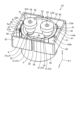
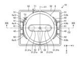
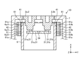
- the perspective view which showed the switch concerning Embodiment 5 The top view which showed the switch concerning Embodiment 5 Sectional view along line XX-XX shown in FIG.
- the top view which showed the switch concerning Embodiment 6 The top view which showed the switch concerning Embodiment 7
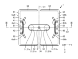
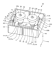
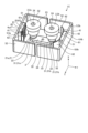
- FIG. 1 is a perspective view showing a switch 1 according to Embodiment 1.
- FIG. FIG. 2 is a plan view showing the switch 1 according to the first embodiment.
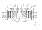
- FIG. 3 is a cross-sectional view along line III-III shown in FIG. In FIG. 2, the fixed contact 21 is illustrated with a two-dot chain line.
- the switch 1 includes two stationary contacts 2 , one movable contact 3 , two magnets 4 , two main yokes 5 and two auxiliary yokes 6 .
- the movable contact 3 is arranged so as to be movable in one direction with respect to the fixed contact 2 .
- the direction in which the movable contactor 3 moves is the X-axis direction
- the direction perpendicular to the X-axis direction is the Y-axis direction
- both the X-axis direction and the Y-axis direction are described.
- the direction orthogonal to is defined as the Z-axis direction.
- the positive direction in the X-axis direction is defined as upward
- the negative direction in the X-axis direction is defined as downward.
- the + direction of the X-axis direction is the direction from the - side to the + side of the X-axis
- the - direction of the X-axis direction is the direction from the + side to the - side of the X-axis.
- the positive direction of the Y-axis is defined as the right direction
- the negative direction of the Y-axis direction is defined as the left direction.
- the + direction of the Y-axis is the direction from the - side to the + side of the Y-axis
- the - direction of the Y-axis is the direction from the + side to the - side of the Y-axis.
- the positive direction in the Z-axis direction is forward, and the negative direction in the Z-axis direction is backward.
- the + direction of the Z-axis direction is the direction from the - side to the + side of the Z-axis
- the - direction of the Z-axis direction is the direction from the + side to the - side of the Z-axis.
- the X-axis direction is the first direction
- the Y-axis direction is the second direction
- the Z-axis direction is the third direction.
- the two fixed contacts 2 are spaced apart from each other in the Y-axis direction. Each fixed contact 2 and movable contact 3 are provided along the X-axis direction. Each fixed contact 2 has one fixed contact 21, a fixed first surface 22 facing the movable contact 3, a fixed second surface 23 facing away from the movable contact 3, and one terminal screw 24 .
- a first fixed contact 2a and a second fixed contact 2b when distinguishing the two fixed contacts 2, they are referred to as a first fixed contact 2a and a second fixed contact 2b.
- a first fixed contact 21a and a second fixed contact 21b when distinguishing the two fixed contacts 21, they are referred to as a first fixed contact 21a and a second fixed contact 21b.
- the outer shape of the fixed contact 2 is not particularly limited, but in the present embodiment, it is a shape in which circles with different diameters are connected along the X-axis direction, and a shape whose diameter decreases toward the movable contact 3. be.
- the fixed contact 21 is provided on the fixed side first surface 22 .
- the first fixed contact 21a and the second fixed contact 21b are spaced apart from each other along the Y-axis direction.
- the terminal screw 24 is screwed into a screw hole that opens on the second surface 23 on the fixed side.
- the terminal screw 24 is a screw for connecting an external terminal (not shown).
- the movable contact 3 is arranged so as to be movable in the X-axis direction with respect to the fixed contact 2 .
- the movable contact 3 is arranged below the fixed contact 2 .
- the shape of the movable contactor 3 is not particularly limited, but in this embodiment, it is generally a rectangular parallelepiped that is longer in the Y-axis direction than in the Z-axis direction.
- the movable contact 3 includes two movable contacts 31 capable of contacting and separating from the fixed contact 21 of each fixed contact 2 , a movable side first surface 32 facing the fixed contact 2 , and the fixed contact 2 . has a movable side second surface 33 facing the opposite side.
- the movable contact 31 is provided on the first surface 32 on the movable side.
- a through hole 34 is formed in the center of the movable contactor 3 so as to penetrate in the X-axis direction.
- the through-hole 34 penetrates the movable contact 3 from the movable-side first surface 32 to the movable-side second surface 33 .
- a shaft (not shown) is inserted through the through hole 34 .
- a first movable contact 31a and a second movable contact 31b are referred to as a first movable contact 31a and a second movable contact 31b.
- the two movable contacts 31 are spaced apart from each other in the Y-axis direction.
- an imaginary straight line extending along the Z-axis direction through the through hole 34, which is the center of the movable contact 3 is defined as a first center line C1.
- An imaginary straight line extending along the Y-axis direction through the through hole 34, which is the center of the movable contact 3, is defined as a second center line C2.
- the first movable contact 31a is arranged on the left side of the movable contactor 3 across the first center line C1.
- the positions of the first movable contact 31a and the first fixed contact 21a match in the Y-axis direction and the Z-axis direction.
- the first movable contact 31a can come into contact with and separate from the first fixed contact 21a.
- the second movable contact 31b is arranged on the other right side of the movable contact 3 across the first center line C1.
- the second movable contact 31b and the second fixed contact 21b are aligned in the Y-axis direction and the Z-axis direction.
- the second movable contact 31b can come into contact with and separate from the second fixed contact 21b.
- the fixed contact 21 may be formed separately from the fixed contact 2 and connected to the fixed contact 2 , or may be formed integrally with the fixed contact 2 .
- the movable contact 31 may be formed separately from the movable contact 3 and connected to the movable contact 3 , or may be formed integrally with the movable contact 3 .
- the two magnets 4 are spaced apart from each other in the Y-axis direction with the movable contact 3 interposed therebetween.
- the first magnet 4a and the second magnet 4b are referred to as the first magnet 4a and the second magnet 4b.
- Each magnet 4 is spaced apart from the movable contact 3 in the Y-axis direction and serves as magnetic field generating means for generating a magnetic field around the movable contact 31 and the fixed contact 21 .
- the magnet 4 is a permanent magnet and magnetically attracts the main yoke 5 and the auxiliary yoke 6 .
- a ferrite magnet or a neodymium magnet, for example, is used for the magnet 4 .
- Magnet 4 is formed in a rectangular parallelepiped shape.
- Each magnet 4 has a first magnetic pole surface 41 facing the movable contact 3 and a second magnetic pole surface 42 facing away from the movable contact 3 .
- the polarities of the first magnetic pole faces 41 of the magnets 4 are the same.
- the polarity of the first magnetic pole face 41 is N pole in this embodiment.
- the polarities of the second magnetic pole faces 42 of the magnets 4 are the same as each other.
- the polarity of the second magnetic pole face 42 is S pole in this embodiment.
- the main yoke 5 is a magnetic body that is directly connected to the second magnetic pole face 42 of each magnet 4 one by one.
- the main yoke 5 is made of a magnetic material such as electromagnetic soft iron or electrogalvanized steel.
- Each main yoke 5 is directly connected to the second magnetic pole surface 42 and extends in the Z-axis direction from the second magnetic pole surface 42 so as to extend from the magnet 4 and the movable contact 3 to one side and the other side in the Z-axis direction. It has a projecting first connecting portion 51 .
- Each main yoke 5 extends in the Y-axis direction from both ends of the first connecting portion 51 along the Z-axis direction, and is arranged on both sides of the magnet 4 and the movable contact 3 along the Z-axis direction. has an arm portion 52 of .
- the first connecting portion 51 is formed in a plate shape that is wider in the Z-axis direction than the magnet 4, the auxiliary yoke 6 and the movable contact 3.
- the first connecting portion 51 is arranged at a position overlapping with the magnet 4, the auxiliary yoke 6 and the movable contact 3 in the X-axis direction and the Z-axis direction.
- the arm portion 52 is formed in a plate shape having the same plate thickness as the first connection portion 51 .
- the arm portion 52 is arranged at a position where it overlaps with the magnet 4, the auxiliary yoke 6 and the movable contact 3 in the X-axis direction and the Y-axis direction and is separated from the magnet 4, the auxiliary yoke 6 and the movable contact 3 in the Z-axis direction.
- the arm portion 52 of the first main yoke 5a is connected to the first magnet 4a, the first auxiliary yoke 6a described later, and the portion of the movable contactor 3 on the left side of the first center line C1 in the X-axis direction and They are provided at overlapping positions in the Y-axis direction.
- the arm portion 52 of the second main yoke 5b is connected to the second magnet 4b, the second auxiliary yoke 6b described later, and the portion of the movable contactor 3 on the right side of the first center line C1 in the X-axis direction and They are provided at overlapping positions in the Y-axis direction.
- the arm portion 52 of the first main yoke 5a and the arm portion 52 of the second main yoke 5b are aligned in the Z-axis direction.
- a gap is provided between the tip of the arm portion 52 of the first main yoke 5a and the tip of the arm portion 52 of the second main yoke 5b.
- the auxiliary yokes 6 are magnetic bodies that are directly connected to the first magnetic pole faces 41 of the magnets 4 one by one. Hereinafter, when distinguishing between the two auxiliary yokes 6, they are referred to as a first auxiliary yoke 6a and a second auxiliary yoke 6b.
- the auxiliary yoke 6 is made of a magnetic material such as electromagnetic soft iron or electrogalvanized steel.
- Auxiliary yoke 6 is arranged between magnet 4 and movable contact 3 .
- the auxiliary yoke 6 is arranged apart from the movable contact 3 in the Y-axis direction.
- Each auxiliary yoke 6 is formed in a plate shape that is wider in the Z-axis direction than the first magnetic pole surface 41 .
- the plate thickness of the main yoke 5 and the plate thickness of the auxiliary yoke 6 are the same in this embodiment.
- Each auxiliary yoke 6 has a second connection portion 61 directly connected to the first magnetic pole face 41 .
- Each auxiliary yoke 6 extends in the Z-axis direction from both ends of the second connection portion 61 along the Z-axis direction beyond the first magnetic pole surface 41 , and moves away from the second connection portion 61 so that the movable contact is increased. It has a pair of extensions 62 that extend closer to 3.
- Each extending portion 62 protrudes from the first magnetic pole surface 41 to one side and the other side in the Z-axis direction.
- Each extending portion 62 extends in a curved shape so as to approach the movable contactor 3 as it goes from the first magnetic pole surface 41 toward the arm portion 52 .
- Each extending portion 62 may extend linearly so as to approach the movable contactor 3 as it goes from the first magnetic pole surface 41 toward the arm portion 52 .
- the switch 1 includes a case 7.
- the case 7 is a member made of resin or metal that houses the fixed contact 2 , movable contact 3 , magnet 4 , main yoke 5 and auxiliary yoke 6 .
- members such as a shaft, a spring, and a coil necessary for moving the movable contact 3 are arranged below the movable contact 3.
- the case 7 is a hollow housing that also accommodates the shaft. is formed in the shape of a box.
- each movable contact 31 is separated from each fixed contact 21, and each movable contact 31 is separated from each other.
- Each fixed contact 21 is electrically cut off.
- the magnetic force generated by the coil causes the movable contact 3 to move toward the fixed contact 2 against the spring force of the spring. , and each movable contact 31 and each fixed contact 21 are electrically connected.
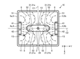
- FIG. FIG. 4 is a plan view for explaining the effect of the switch 1E according to the comparative example.
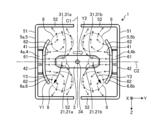
- FIG. 5 is a plan view for explaining the effects of the switch 1 according to the first embodiment.
- the switch 1 according to the present embodiment shown in FIG. 5 has the auxiliary yoke 6, whereas the switch 1E according to the comparative example shown in FIG.
- Arrow Y1 shown in FIGS. 4 and 5 indicates the direction of magnetic flux flow
- arrow Y2 indicates the direction of current flowing through movable contact 3
- arrow Y3 indicates the direction of arc driving.
- the arc extinguishing space 8 in which the arc is extinguished is schematically illustrated by an elliptical broken line.
- the arc extinguishing space 8 is a space existing between the movable contactor 3 and the arm portion 52, and refers to a space in which the arc can be extinguished by extending the arc to the space.
- the arc-extinguishing space 8 exists between the movable contact 3 and each arm portion 52 of the first main yoke 5a, and is located between the movable contact 3 and each arm portion 52 of the second main yoke 5b. There is one each between
- the direction of the current flowing through the movable contact 3 is the direction along the Y-axis direction from the first magnet 4a toward the second magnet 4b, and Assume that the polarity of the magnetic pole surface 41 is the same N pole.
- the magnetic flux generated from the magnet 4 flows toward the movable contact 3 and then toward the main yoke 5, and the first magnet 4a causes the magnetic flux to flow toward the main yoke 5.
- the generated magnetic field and the magnetic field generated by the second magnet 4b are symmetrical with respect to the first center line C1. Since the Lorentz force in the arrow Y3 direction acts on the arc, the arc is driven along the arrow Y3 direction.
- the arc generated between the first movable contact 31a and the first fixed contact 21a drives the movable contact 3 leftward and forward.
- the arc generated between the second movable contact 31b and the second fixed contact 21b drives the movable contact 3 rightward and forward.
- the magnetic flux generated from the magnet 4 closes in a shorter path than the switch 1 according to the present embodiment having the auxiliary yoke 6.
- the magnetic flux density in the arc extinguishing space 8 is reduced, and the effect of extending the arc is reduced.
- the switch 1 is provided with the auxiliary yoke 6 directly connected to the first magnetic pole surface 41 of the magnet 4, so that the switch 1E according to the comparative example , the magnetic flux induced to the arc extinguishing space 8 increases, and the magnetic flux density in the arc extinguishing space 8 can be increased. Therefore, the arc can be extended longer than conventionally. As a result, the arc extinguishing performance can be enhanced, and the circuit current interrupting performance of the switch 1 can be enhanced.
- the auxiliary yoke 6 includes a second connecting portion 61 directly connected to the first magnetic pole surface 41, and both ends of the second connecting portion 61 along the Z-axis direction. and a pair of extending portions 62 extending in the direction from the first magnetic pole surface 41 and extending closer to the movable contact 3 as the distance from the second connecting portion 61 increases.
- the magnetic flux induced to the arc extinguishing space 8 is further increased, and the magnetic flux density of the arc extinguishing space 8 can be further increased. Therefore, the arc can be extended longer than conventionally.
- the switch 1 is provided with the auxiliary yoke 6 arranged between the magnet 4 and the movable contact 3, thereby inducing the magnetic flux toward the movable contact 31 and the fixed contact 21.
- the magnetic flux density around the movable contact 31 and the fixed contact 21 can be increased to quickly drive the arc away from the movable contact 31 and the fixed contact 21 .
- the driving direction of the arc indicated by the arrow Y3 is symmetrical with respect to the illustrated example with respect to the second center line C2.
- the arc generated between the first movable contact 31a and the first fixed contact 21a drives the movable contact 3 leftward and backward.
- the arc generated between the second movable contact 31b and the second fixed contact 21b drives the movable contact 3 rightward and backward. Therefore, regardless of the direction Y2 of the current flowing through the movable contactor 3, the arc can be extended longer than before.
- the magnetic field generating means is the magnet 4 in this embodiment, it is not particularly limited as long as it can generate a magnetic field.
- the magnetic field generating means may be, for example, coils.
- the polarity of the first magnetic pole face 41 of each magnet 4 was N pole in the present embodiment, but may be S pole.
- the auxiliary yoke 6 having the second connection portion 61 and the pair of extending portions 62 is used in the present embodiment, the auxiliary yoke 6 without the pair of extending portions 62 may be used.
- the auxiliary yoke 6 extends linearly along the Z-axis direction.
- the auxiliary yoke 6 may or may not extend beyond the first magnetic pole surface 41 in one and the other directions in the Z-axis direction.
- FIG. 6 is a plan view showing the switch 1A according to the second embodiment.
- FIG. 7 is a cross-sectional view taken along line VII--VII shown in FIG.
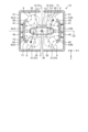
- FIG. 8 is a plan view for explaining the effects of the switch 1A according to the second embodiment.
- the polarities of the first magnetic pole faces 41 of the magnets 4 are different from each other, and the polarities of the second magnetic pole faces 42 of the magnets 4 are different from each other. This is different from the first embodiment described above.
- symbol is attached
- the polarity of the first magnetic pole surface 41 of the first magnet 4a is N pole in this embodiment.
- the polarity of the first magnetic pole surface 41 of the second magnet 4b is S pole in this embodiment.
- the polarity of the second magnetic pole surface 42 of the first magnet 4a is S pole in this embodiment.
- the polarity of the second magnetic pole surface 42 of the second magnet 4b is N pole in this embodiment.
- the configuration of fixed contactor 2 and the like is the same as in the first embodiment.
- the flow of magnetic flux generated from the second magnet 4b is opposite to the flow of magnetic flux in Embodiment 1 shown in FIG.
- the magnetic flux generated from the second magnet 4b flows toward each arm portion 52 after passing through the first connection portion 51 (not shown in FIG. 8). Then, the magnetic flux generated from the second magnet 4b flows from each arm portion 52 toward the movable contact 3 and then toward the second magnet 4b. Part of the magnetic flux generated from the first magnet 4a flows toward the second magnet 4b along the direction in which the movable contact 3 extends.
- the magnetic field generated by the first magnet 4a is symmetrical with respect to the second center line C2.
- the magnetic field generated by the second magnet 4b is symmetrical with respect to the second center line C2. Since the Lorentz force in the arrow Y3 direction acts on the arc, the arc is driven along the arrow Y3 direction. Specifically, the arc generated between the first movable contact 31a and the first fixed contact 21a drives the movable contact 3 leftward and forward. On the other hand, the arc generated between the second movable contact 31b and the second fixed contact 21b drives the movable contact 3 rightward and backward.
- the first magnetic pole faces 41 of the magnets 4 have different polarities, so that the arc generated between the first movable contact 31a and the first fixed contact 21a and the second
- the arc generated between the second movable contact 31b and the second fixed contact 21b are driven in opposite directions in the Y-axis direction and the Z-axis direction. Therefore, it is possible to suppress the two arcs from connecting and short-circuiting, so that the arc extinguishing performance can be enhanced, and the circuit current interrupting performance of the switch 1A can be enhanced.
- FIG. 9 is a perspective view showing a switch 1B according to the third embodiment.
- FIG. 10 is a plan view showing a switch 1B according to the third embodiment.
- 11 is a cross-sectional view along line XI-XI shown in FIG.
- This embodiment differs from the first embodiment in that the thickness T1 of the main yoke 5 and the thickness T2 of the auxiliary yoke 6 are different from each other.
- symbol is attached
- the plate thickness T2 of the auxiliary yoke 6 is thinner than the plate thickness T1 of the main yoke 5.
- the cross-sectional area of the extending portion 62 when cut in the direction orthogonal to the X-axis direction is smaller than the cross-sectional area of the arm portion 52 when cut in the direction orthogonal to the X-axis direction.
- the auxiliary yoke 6 since the plate thickness T2 of the auxiliary yoke 6 is thinner than the plate thickness T1 of the main yoke 5, the auxiliary yoke 6 is easily magnetically saturated. Therefore, the magnetic flux generated from the magnet 4 tends to leak toward the movable contact 31 and the fixed contact 21 via the auxiliary yoke 6, and the magnetic flux density around the movable contact 31 and the fixed contact 21 can be increased. This allows the arc to be driven much more quickly.
- the plate thickness T2 of the auxiliary yoke 6 is thinner than the plate thickness T1 of the main yoke 5 over the entirety of the auxiliary yoke 6. It should be thinner than thick. If the cross-sectional area of the auxiliary yoke 6 is made smaller than that of the main yoke 5, the magnetic saturation of the auxiliary yoke 6 can be easily generated. A configuration in which the plate thickness is thinner than T1 is shown.
- the cross-sectional area of the auxiliary yoke 6 As a configuration for making the cross-sectional area of the auxiliary yoke 6 smaller than that of the main yoke 5, in addition to the configuration in which the thickness T1 of the main yoke 5 and the thickness T2 of the auxiliary yoke 6 are changed as in the present embodiment, for example, there is a configuration in which the length of the main yoke 5 along the X-axis direction and the length of the auxiliary yoke 6 along the X-axis direction are changed, and a configuration in which the auxiliary yoke 6 is notched.
- the cross-sectional area of the auxiliary yoke 6 is made smaller than that of the main yoke 5 , at least the cross-sectional area of the extending portion 62 should be smaller than the cross-sectional area of the arm portion 52 .
- FIG. 12 is a perspective view showing a switch 1C according to the fourth embodiment.
- FIG. 13 is a plan view showing a switch 1C according to the fourth embodiment.
- 14 is a cross-sectional view along line XIV-XIV shown in FIG. 13.
- FIG. 15 is a plan view showing the auxiliary yoke 6 according to the fourth embodiment.
- FIG. 16 is a front view showing the auxiliary yoke 6 according to the fourth embodiment.
- FIG. 17 is a perspective view showing the auxiliary yoke 6 according to the fourth embodiment.
- This embodiment differs from the third embodiment in that the auxiliary yoke 6 is provided with a hole 61a.
- symbol is attached
- the second connecting portion 61 of the auxiliary yoke 6 is formed with a plurality of holes 61a penetrating in the Y-axis direction.
- the holes 61 a are formed along the in-plane direction of the first magnetic pole surface 41 .
- the hole 61a is an elongated hole longer in the Z-axis direction than in the X-axis direction.
- the plurality of holes 61a are spaced apart from each other in the X-axis direction.
- the plurality of holes 61a may be elongated holes that are longer in the X-axis direction than in the Z-axis direction, and may be spaced apart from each other in the Z-axis direction. and may be spaced apart from each other in the X-axis direction and the Z-axis direction.
- the second connection portion 61 of the auxiliary yoke 6 is formed with a plurality of holes 61a penetrating in the Y-axis direction. is likely to leak toward the movable contact 31 and the fixed contact 21 via the auxiliary yoke 6, and the magnetic flux density around the movable contact 31 and the fixed contact 21 can be increased. This allows the arc to be driven much more quickly.
- the thickness T2 of the auxiliary yoke 6 is made thinner than the thickness T1 of the main yoke 5, and then the thickness T2 of the auxiliary yoke 6 as shown in FIGS.
- the present invention is not limited to this.
- the plate thickness T2 of the auxiliary yoke 6 may be the same as the plate thickness T1 of the main yoke 5, and the hole 61a may be formed in the second connection portion 61 of the auxiliary yoke 6. FIG. Even in this way, the effect of driving the arc more quickly can be obtained.
- FIG. 18 is a perspective view showing a switch 1D according to the fifth embodiment.
- FIG. 19 is a plan view showing a switch 1D according to the fifth embodiment.
- 20 is a cross-sectional view taken along line XX-XX shown in FIG. 19.
- FIG. This embodiment differs from the fourth embodiment in that an insulating member 9 is provided between the movable contactor 3 and each auxiliary yoke 6 .
- symbol is attached
- the insulating member 9 is provided so as to surround the movable contactor 3 .
- the insulating member 9 is provided between the movable contact 3 and each auxiliary yoke 6 and each arm portion 52 .
- the insulating member 9 separates the movable contact 3 from each auxiliary yoke 6 and each arm portion 52 .
- the insulating member 9 thermally insulates between the movable contact 3 and each auxiliary yoke 6 and each arm portion 52 .
- the shape of the insulating member 9 is cylindrical in this embodiment, but is not particularly limited as long as it can thermally insulate at least between the movable contact 3 and the auxiliary yoke 6 .
- the shape of the insulating member 9 may be a rectangular cylinder.
- the material of the insulating member 9 may be, for example, an inorganic insulating material such as ceramic, or an organic insulating material such as a synthetic resin material.
- the arc When an arc is generated between the movable contact 31 and the fixed contact 21 shown in FIG. 20, the arc is stretched by the electromagnetic force, but may come into contact with the auxiliary yoke 6 depending on the driving conditions of the arc.
- the heat of the high-temperature arc is transferred to the magnet 4 via the auxiliary yoke 6, thermally demagnetizing the magnet 4, and the magnetic force performance of the magnet 4 may deteriorate.
- the auxiliary yoke 6 has high conductivity, the arc will continue to contact the auxiliary yoke 6, and the auxiliary yoke 6 may be thermally worn.
- an insulating member 9 is provided between the movable contact 3 and the auxiliary yoke 6 to thermally insulate the movable contact 3 and the auxiliary yoke 6, thereby reducing the arc contact with the auxiliary yoke 6 can be prevented. Therefore, it is possible to prevent deterioration of the magnetic force performance of the magnet 4 due to thermal demagnetization and to prevent thermal wear of the auxiliary yoke 6 . Further, in the present embodiment, since the insulating member 9 is also provided between the movable contactor 3 and the arm portion 52, contact between the arc and the arm portion 52 can be prevented. 52 can be prevented from thermal wear.
- FIG. 21 is a plan view showing the switch 1F according to the sixth embodiment.
- the present embodiment differs from the first to fifth embodiments in that the extended portion 62 of the auxiliary yoke 6 is extended until the center P1 of the movable contact 31 coincides with the position in the Y-axis direction.
- symbol is attached
- the center of the movable contact 31 in the Y-axis direction is defined as the center P1 of the movable contact 31
- the extending portion 62 of the auxiliary yoke 6 is located at a position in the Y-axis direction that is aligned with the center P1 of the movable contact 31. Extends until it matches.
- the center P1 of the movable contact 31 is the center of the movable contact 31 in the extending direction of the movable contact 3 . That is, the center P1 of the movable contact 31 is the center of the movable contact 31 in the Y-axis direction in FIG.
- an imaginary straight line extending along the Z-axis direction through the center P1 of the movable contact 31 will be referred to as a third center line C3.
- the extending portion 62 of the first auxiliary yoke 6a extends until the position in the Y-axis direction coincides with the center P1 of the first movable contact 31a that is closer in the Y-axis direction among the two movable contacts 31 .
- the tip 62a of the extending portion 62 of the first auxiliary yoke 6a reaches the third center line C3 passing through the center P1 of the first movable contact 31a.
- the extending portion 62 of the second auxiliary yoke 6b extends until the position in the Y-axis direction coincides with the center P1 of the second movable contact 31b that is closer in the Y-axis direction out of the two movable contacts 31 .
- the tip 62a of the extending portion 62 of the second auxiliary yoke 6b reaches the third center line C3 passing through the center P1 of the second movable contact 31b.
- the extending portion 62 of the auxiliary yoke 6 extends toward the movable contact 3 in the Y-axis direction as it moves away from the second connecting portion 61 .
- the extending portion 62 of the auxiliary yoke 6 extends away from the movable contact 3 in the Z-axis direction as it separates from the second connecting portion 61 .
- a tip 62a of the extending portion 62 of the auxiliary yoke 6 is located at a position farthest from the movable contactor 3 in the extending portion 62 in the Z-axis direction.
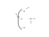
- the extended portion 62 of the auxiliary yoke 6 has a shape along the insulating member 9 . Since the insulating member 9 shown in FIG.
- the extending portion 62 of the auxiliary yoke 6 has a circular arc along the insulating member 9 .
- the shape of the extending portion 62 of the auxiliary yoke 6 is appropriately changed according to the shape of the insulating member 9 .
- the shape of the insulating member 9 is a square tube, an elliptical tube, or the like
- the shape of the extending portion 62 of the auxiliary yoke 6 is linear along the Y-axis direction.
- the extension 62a of the auxiliary yoke 6 extends beyond the center P1 of the movable contact 31 in the Y-axis direction, that is, if the extension 62a of the extension 62 of the auxiliary yoke 6 reaches the tip 62a
- the extending portion 62 of the auxiliary yoke 6 extends until the center P1 of the movable contact 31 coincides with the position in the Y-axis direction. , the contact between the arc generated between the first movable contact 31a and the first fixed contact 21a and the arc generated between the second movable contact 31b and the second fixed contact 21b is reduced. It is possible to suppress the deterioration of the performance of extinguishing the arc.
- FIG. 22 is a plan view showing a switch 1G according to Embodiment 7.
- the separation wall 63 is provided in the portion of the insulating member 9 between the extending portion 62 of the auxiliary yoke 6 and the center P2 of the movable contact 3 in the Y-axis direction. It differs from form 6.
- the same reference numerals are given to the parts that overlap with the first to sixth embodiments, and the description thereof will be omitted.
- the switch 1G includes a movable contact 3, a movable contact 31, a fixed contact 2 and a fixed contact 21, a magnet 4, a main yoke 5 and an auxiliary yoke 6 in the Y-axis direction and the Z-axis direction. It has an insulating member 9 that partitions between. The insulating member 9 electrically, thermally and spatially separates the movable contact 3, the movable contact 31, the fixed contact 2 and the fixed contact 21 from the magnet 4, the main yoke 5 and the auxiliary yoke 6. .
- a portion of the insulating member 9 located between the extending portion 62 and the center P2 of the movable contact 3 in the Y-axis direction when the center P2 of the movable contact 3 is defined as the center P2 of the movable contact 3 in the Y-axis direction. is provided with a separation wall 63 . It is preferable that the separation wall 63 is located at a position that coincides with the tip 62a of the extension portion 62 in the Y-axis direction, or at a position closer to the tip 62a of the extension portion 62 than the center P2 of the movable contactor 3 in the Y-axis direction. .
- the center P2 of the movable contact 3 is the center of the movable contact 3 in the extending direction of the movable contact 3 . That is, the center P2 of the movable contact 3 is the center of the movable contact 3 in the Y-axis direction in FIG.
- the center P2 of the movable contact 3 and the center P1 of the movable contact 31 are aligned in the Z-axis direction.
- the center P2 of the movable contact 3 and the center P1 of the movable contact 31 are displaced in the Y-axis direction.
- the center P2 of the movable contact 3 is positioned between the centers P1 of the two movable contacts 31 in the Y-axis direction.
- the center P2 of the movable contact 3 is positioned between the centers P1 of the two movable contacts 31 in the Y-axis direction.
- the center P2 of the movable contact 3 is located farther from the magnet 4, the first connecting portion 51 and the second connecting portion 61 than the center P1 of the movable contact 31 in the Y-axis direction.
- the first center line C1 is an imaginary straight line passing through the center P2 of the movable contact 3 and extending along the Z-axis direction.
- the separation wall 63 extends from the insulating member 9 toward the movable contact 3 in the Z-axis direction. Although the number of separation walls 63 is four in this embodiment, at least one is sufficient. When distinguishing the four separation walls 63, they are referred to as a first separation wall 63a, a second separation wall 63b, a third separation wall 63c, and a fourth separation wall 63d.
- the separation wall 63 is provided between the extending portion 62 of the auxiliary yoke 6 and the center P2 of the movable contact 3 in the Y-axis direction. In other words, the separation wall 63 is provided between the extending portion 62 of the auxiliary yoke 6 and the first center line C1 in the Y-axis direction.
- One separation wall 63 is provided between each extending portion 62 and the first center line C1 in the Y-axis direction.
- Two separation walls 63 are provided between one extending portion 62 of the first auxiliary yoke 6a and one extending portion 62 of the second auxiliary yoke 6b in the Y-axis direction.
- a first separation wall 63a and a second separation wall 63b are provided between one extending portion 62 of the first auxiliary yoke 6a and one extending portion 62 of the second auxiliary yoke 6b. .
- the first separation wall 63a and the second separation wall 63b are arranged apart from each other in the Y-axis direction. Although the first separation wall 63a and the second separation wall 63b are formed independently of each other in the present embodiment, they may be integrated.
- one separation wall 63 is provided between one extending portion 62 of the first auxiliary yoke 6a and one extending portion 62 of the second auxiliary yoke 6b. It may also be provided with two walls spaced apart from each other and extending in the Z-axis direction toward the movable contact 3 .
- Two separation walls 63 are provided between the other extending portion 62 of the first auxiliary yoke 6a and the other extending portion 62 of the second auxiliary yoke 6b in the Y-axis direction.
- a third separation wall 63c and a fourth separation wall 63d are provided between the other extending portion 62 of the first auxiliary yoke 6a and the other extending portion 62 of the second auxiliary yoke 6b. .
- the third separation wall 63c and the fourth separation wall 63d are arranged apart from each other in the Y-axis direction.
- the third separation wall 63c and the fourth separation wall 63d are formed independently of each other in the present embodiment, they may be integrated.
- one separation wall 63 is provided between the other extending portion 62 of the first auxiliary yoke 6a and the other extending portion 62 of the second auxiliary yoke 6b. It may also be provided with two walls spaced apart from each other and extending in the Z-axis direction toward the movable contact 3 . In the example of FIG. 22, the extending portion 62 of the auxiliary yoke 6 extends until the center P1 of the movable contact 31 coincides with the position in the Y-axis direction. does not have to extend until they match.
- the arc When an arc is generated between the movable contact 31 and the fixed contact 21 shown in FIG. 22, the arc is extended toward the tip 62a of the extended portion 62 of the auxiliary yoke 6 by electromagnetic force.
- the closer the tip 62a of the extending portion 62 of the auxiliary yoke 6 is to the first center line C1 the more the contact between the first movable contact 31a and the first fixed contact 21a increases.
- the arc generated between them and the arc generated between the second movable contact 31b and the second fixed contact 21b are likely to come into contact with each other. This may reduce the arc resistance by merging the two arcs into one, degrading the ability to extinguish the arc.
- a portion of the insulating member 9 located between the extending portion 62 and the center P2 of the movable contact 3 in the Y-axis direction has a A separation wall 63 extending in the Z-axis direction is provided to separate the arc extended near the tip 62a of the extension 62 of the first auxiliary yoke 6a and the extension 62 of the second auxiliary yoke 6b.
- the arc extended close to the tip 62a is separated from each other. In this state, the arc can be kept extended to the arc extinguishing space 8 (not shown in FIG. 22), so that the arc can be quickly extinguished.
- FIG. 23 is a plan view showing a switch 1H according to the eighth embodiment.
- This embodiment is different from the sixth and seventh embodiments in that an insulating wall 64 is provided at a portion of the insulating member 9 that coincides with the center P2 of the movable contact 3 in the Y-axis direction.
- the same reference numerals are given to the parts that overlap with Embodiments 1 to 7, and the description thereof is omitted.
- the switch 1H includes a movable contact 3, a movable contact 31, a fixed contact 2 and a fixed contact 21, a magnet 4, a main yoke 5 and an auxiliary yoke 6 in the Y-axis direction and the Z-axis direction. It has an insulating member 9 that partitions between. The insulating member 9 electrically, thermally and spatially separates the movable contact 3, the movable contact 31, the fixed contact 2 and the fixed contact 21 from the magnet 4, the main yoke 5 and the auxiliary yoke 6. .
- an insulating wall 64 is formed in a portion of the insulating member 9 that coincides with the center P2 of the movable contact 3 in the Y-axis direction. is provided.
- the insulating wall 64 extends from the insulating member 9 toward the movable contact 3 in the Z-axis direction. Although the number of insulating walls 64 is two in this embodiment, at least one is sufficient. When distinguishing the two insulating walls 64, they are referred to as a first insulating wall 64a and a second insulating wall 64b.
- the insulating wall 64 is aligned with the center P2 of the movable contact 3 in the Y-axis direction. In other words, the insulating wall 64 is aligned with the first center line C1 in the Y-axis direction.
- One insulating wall 64 is provided on one side and the other side of the movable contact 3 in the Z-axis direction.
- One insulating wall 64 is provided between one extending portion 62 of the first auxiliary yoke 6a and one extending portion 62 of the second auxiliary yoke 6b in the Y-axis direction.
- a first insulating wall 64a is provided between one extending portion 62 of the first auxiliary yoke 6a and one extending portion 62 of the second auxiliary yoke 6b.
- One insulating wall 64 is provided between the other extending portion 62 of the first auxiliary yoke 6a and the other extending portion 62 of the second auxiliary yoke 6b in the Y-axis direction.
- a second insulating wall 64b is provided between the other extending portion 62 of the first auxiliary yoke 6a and the other extending portion 62 of the second auxiliary yoke 6b.
- the two insulating walls 64 are provided at symmetrical positions in the Z-axis direction with the center P2 of the movable contact 3 interposed therebetween.
- the extending portion 62 of the auxiliary yoke 6 extends until the center P1 of the movable contact 31 coincides with the position in the Y-axis direction. does not have to extend until they match.
- a portion of the insulating member 9 that coincides with the center P2 of the movable contact 3 in the Y-axis direction has a portion extending from the insulating member 9 toward the movable contact 3 in the Z-axis direction.
- An insulating wall 64 is provided.
- the arc extended to the tip 62a of the extended portion 62 of the first auxiliary yoke 6a and the arc extended to the tip 62a of the extended portion 62 of the second auxiliary yoke 6b are separated from each other. In this state, it is possible to maintain the state in which the arc is extended to the arc extinguishing space 8 (not shown in FIG. 23), so that the arc can be quickly extinguished.
- the arc generated between the first movable contact 31a and the first fixed contact 21a and the arc generated between the second movable contact 31b and the second fixed contact 21b It is possible to maintain a state of being separated from the arc and a state of being extended to the vicinity of the tip 62a of the extended portion 62 of the auxiliary yoke 6.
- the insulating wall 64 is positioned so as not to hinder the movement of the arc in the Z-axis direction.
- An arc generated between the first movable contact 31a and the first fixed contact 21a and an arc generated between the second movable contact 31b and the second fixed contact 21b with a simpler configuration than the configuration 7 can be kept separate from Which of the configurations of the seventh and eighth embodiments described above is adopted, or whether both configurations of the seventh and eighth embodiments are used together depends on the performance required for the product, the shape of the insulating member 9, and the like. It can be selected as appropriate.
- the two-point contact structure is provided with two fixed contacts 21 and two movable contacts 31, but the one-point contact structure is provided with one fixed contact 21 and one movable contact 31.
- the one-point contact structure one magnet 4, one main yoke 5 and one auxiliary yoke 6 are also provided.
Landscapes
- Physics & Mathematics (AREA)
- Electromagnetism (AREA)
- Arc-Extinguishing Devices That Are Switches (AREA)
Abstract
Description
図1は、実施の形態1にかかる開閉器1を示した斜視図である。図2は、実施の形態1にかかる開閉器1を示した平面図である。図3は、図2に示されたIII-III線に沿った断面図である。図2では、固定接点21を2点鎖線で図示している。図1に示すように、開閉器1は、2つの固定接触子2と、1つの可動接触子3と、2つの磁石4と、2つの主ヨーク5と、2つの補助ヨーク6とを備える。可動接触子3は、固定接触子2に対して1方向に移動可能に配置されている。
次に、図6から図8を参照して、実施の形態2にかかる開閉器1Aについて説明する。図6は、実施の形態2にかかる開閉器1Aを示した平面図である。図7は、図6に示されたVII-VII線に沿った断面図である。図8は、実施の形態2にかかる開閉器1Aの効果を説明するための平面図である。本実施の形態では、各磁石4の第1の磁極面41の極性が互いに異極となっている点および各磁石4の第2の磁極面42の極性が互いに異極となっている点が前記した実施の形態1と相違する。なお、実施の形態2では、前記した実施の形態1と重複する部分については、同一符号を付して説明を省略する。
次に、図9から図11を参照して、実施の形態3にかかる開閉器1Bについて説明する。図9は、実施の形態3にかかる開閉器1Bを示した斜視図である。図10は、実施の形態3にかかる開閉器1Bを示した平面図である。図11は、図10に示されたXI-XI線に沿った断面図である。本実施の形態では、主ヨーク5の板厚T1と補助ヨーク6の板厚T2とが互いに異なっている点が前記した実施の形態1と相違する。なお、実施の形態3では、前記した実施の形態1と重複する部分については、同一符号を付して説明を省略する。
次に、図12から図17を参照して、実施の形態4にかかる開閉器1Cについて説明する。図12は、実施の形態4にかかる開閉器1Cを示した斜視図である。図13は、実施の形態4にかかる開閉器1Cを示した平面図である。図14は、図13に示されたXIV-XIV線に沿った断面図である。図15は、実施の形態4における補助ヨーク6を示した平面図である。図16は、実施の形態4における補助ヨーク6を示した正面図である。図17は、実施の形態4における補助ヨーク6を示した斜視図である。本実施の形態では、補助ヨーク6に孔61aを形成した点が前記した実施の形態3と相違する。なお、実施の形態4では、前記した実施の形態1,3と重複する部分については、同一符号を付して説明を省略する。
次に、図18から図20を参照して、実施の形態5にかかる開閉器1Dについて説明する。図18は、実施の形態5にかかる開閉器1Dを示した斜視図である。図19は、実施の形態5にかかる開閉器1Dを示した平面図である。図20は、図19に示されたXX-XX線に沿った断面図である。本実施の形態では、可動接触子3と各補助ヨーク6との間に絶縁部材9を設けた点が前記した実施の形態4と相違する。なお、実施の形態5では、前記した実施の形態1,3,4と重複する部分については、同一符号を付して説明を省略する。
次に、図21を参照して、実施の形態6にかかる開閉器1Fについて説明する。図21は、実施の形態6にかかる開閉器1Fを示した平面図である。本実施の形態では、可動接点31の中心P1とY軸方向における位置が一致するまで補助ヨーク6の延伸部62を延ばした点が前記した実施の形態1から5と相違する。なお、実施の形態6では、前記した実施の形態1から5と重複する部分については、同一符号を付して説明を省略する。
次に、図22を参照して、実施の形態7にかかる開閉器1Gについて説明する。図22は、実施の形態7にかかる開閉器1Gを示した平面図である。本実施の形態では、絶縁部材9のうちY軸方向において補助ヨーク6の延伸部62と可動接触子3の中心P2との間に位置する部分に分離壁63を設けた点が前記した実施の形態6と相違する。なお、実施の形態7では、前記した実施の形態1から6と重複する部分については、同一符号を付して説明を省略する。
次に、図23を参照して、実施の形態8にかかる開閉器1Hについて説明する。図23は、実施の形態8にかかる開閉器1Hを示した平面図である。本実施の形態では、絶縁部材9のうちY軸方向において可動接触子3の中心P2と一致する部分に絶縁壁64を設けた点が前記した実施の形態6,7と相違する。なお、実施の形態8では、前記した実施の形態1から7と重複する部分については、同一符号を付して説明を省略する。
Claims (11)
- 固定接点を有する固定接触子と、
前記固定接点に接触可能な可動接点を有し、前記固定接触子に対して第1の方向に移動可能に配置された可動接触子と、
前記第1の方向と直交する第2の方向に前記可動接触子と離隔して配置されて、前記可動接触子の方を向く第1の磁極面と前記可動接触子とは反対側を向く第2の磁極面とを有する磁界発生部材と、
前記第2の磁極面に接続されて前記第2の磁極面から前記第1の方向および前記第2の方向の両方と直交する第3の方向に延びて前記磁界発生部材および前記可動接触子のそれぞれよりも前記第3の方向の一方と他方とに張り出す第1の接続部と、前記第1の接続部の前記第3の方向に沿った両端部から前記第2の方向に延びて前記磁界発生部材および前記可動接触子の前記第3の方向に沿った両側に配置された一対のアーム部とを有する主ヨークと、
前記第1の磁極面に直接接続された補助ヨークと、
を備えることを特徴とする開閉器。 - 前記磁界発生部材は、永久磁石であり、前記主ヨークおよび前記補助ヨークを磁力で吸着していることを特徴とする請求項1に記載の開閉器。
- 前記補助ヨークは、前記第1の磁極面に直接接続された第2の接続部と、前記第2の接続部の前記第3の方向に沿った両端部から前記第3の方向に前記第1の磁極面よりも延びるとともに前記第2の接続部から離れるにつれて前記可動接触子の方に近付くように延びる一対の延伸部とを有することを特徴とする請求項1または2に記載の開閉器。
- 前記延伸部の断面積は、前記アーム部の断面積よりも小さいことを特徴とする請求項3に記載の開閉器。
- 前記補助ヨークの板厚は、前記主ヨークの板厚より薄いことを特徴とする請求項3または4に記載の開閉器。
- 前記第2の接続部には、前記第2の方向に貫通する孔が形成されていることを特徴とする請求項3から5のいずれか1項に記載の開閉器。
- 前記固定接触子は、前記第2の方向に互いに間隔を空けて2つ配置されており、
前記可動接触子は、各前記固定接触子の前記固定接点に接触可能な2つの前記可動接点を有し、
前記磁界発生部材は、前記可動接触子を間に挟んで前記第2の方向に互いに間隔を空けて2つ配置されており、
前記主ヨークは、各前記磁界発生部材の前記第2の磁極面に1つずつ接続されており、
前記補助ヨークは、各前記磁界発生部材の前記第1の磁極面に1つずつ接続されていることを特徴とする請求項3から6のいずれか1項に記載の開閉器。 - 前記可動接点の前記第2の方向における中心を前記可動接点の中心としたときに、前記延伸部は、前記可動接点の中心と前記第2の方向における位置が一致するまで延びていることを特徴とする請求項7に記載の開閉器。
- 前記第2の方向および前記第3の方向において、前記可動接触子、前記可動接点、前記固定接触子および前記固定接点と、前記磁界発生部材、前記主ヨークおよび前記補助ヨークとの間を仕切る絶縁部材を備えることを特徴とする請求項7または8に記載の開閉器。
- 前記可動接触子の前記第2の方向における中心を前記可動接触子の中心としたときに、前記絶縁部材のうち前記第2の方向において前記延伸部と前記可動接触子の中心との間に位置する部分には、前記絶縁部材から前記可動接触子の方に向かって前記第3の方向に延びる少なくとも1つの分離壁が設けられていることを特徴とする請求項9に記載の開閉器。
- 前記可動接触子の前記第2の方向における中心を前記可動接触子の中心としたときに、前記絶縁部材のうち前記第2の方向において前記可動接触子の中心と一致する部分には、前記絶縁部材から前記可動接触子の方に向かって前記第3の方向に延びる少なくとも1つの絶縁壁が設けられていることを特徴とする請求項9または10に記載の開閉器。
Priority Applications (4)
| Application Number | Priority Date | Filing Date | Title |
|---|---|---|---|
| EP22898269.0A EP4439604A4 (en) | 2021-11-26 | 2022-10-14 | SWITCH |
| US18/698,369 US12620538B2 (en) | 2021-11-26 | 2022-10-14 | Switch |
| JP2023563554A JP7490152B2 (ja) | 2021-11-26 | 2022-10-14 | 開閉器 |
| CN202280077113.4A CN118451524A (zh) | 2021-11-26 | 2022-10-14 | 开闭器 |
Applications Claiming Priority (2)
| Application Number | Priority Date | Filing Date | Title |
|---|---|---|---|
| JP2021-192248 | 2021-11-26 | ||
| JP2021192248 | 2021-11-26 |
Publications (1)
| Publication Number | Publication Date |
|---|---|
| WO2023095485A1 true WO2023095485A1 (ja) | 2023-06-01 |
Family
ID=86539272
Family Applications (1)
| Application Number | Title | Priority Date | Filing Date |
|---|---|---|---|
| PCT/JP2022/038412 Ceased WO2023095485A1 (ja) | 2021-11-26 | 2022-10-14 | 開閉器 |
Country Status (5)
| Country | Link |
|---|---|
| US (1) | US12620538B2 (ja) |
| EP (1) | EP4439604A4 (ja) |
| JP (1) | JP7490152B2 (ja) |
| CN (1) | CN118451524A (ja) |
| WO (1) | WO2023095485A1 (ja) |
Citations (2)
| Publication number | Priority date | Publication date | Assignee | Title |
|---|---|---|---|---|
| WO2014155874A1 (ja) * | 2013-03-27 | 2014-10-02 | 三菱電機株式会社 | 開閉装置 |
| JP2021051978A (ja) | 2019-09-26 | 2021-04-01 | パナソニックIpマネジメント株式会社 | 接点装置および当該接点装置を搭載した電磁継電器 |
Family Cites Families (10)
| Publication number | Priority date | Publication date | Assignee | Title |
|---|---|---|---|---|
| JP2010251542A (ja) | 2009-04-16 | 2010-11-04 | Sumco Corp | 加工面判別方法及び加工面判別装置、並びに、シリコンウェーハの製造方法 |
| JP5629107B2 (ja) | 2010-03-25 | 2014-11-19 | パナソニック株式会社 | 接点装置 |
| EP2608235B1 (en) | 2010-03-25 | 2017-12-20 | Panasonic Intellectual Property Management Co., Ltd. | Contact device |
| JP5307779B2 (ja) | 2010-08-31 | 2013-10-02 | 富士電機機器制御株式会社 | 電磁開閉器 |
| JP5884034B2 (ja) | 2011-03-22 | 2016-03-15 | パナソニックIpマネジメント株式会社 | 接点装置 |
| JP5864902B2 (ja) * | 2011-05-19 | 2016-02-17 | 富士電機機器制御株式会社 | 電磁接触器の消弧室組立方法 |
| JP5965197B2 (ja) * | 2012-04-13 | 2016-08-03 | 富士電機機器制御株式会社 | 開閉器 |
| JP2016072021A (ja) * | 2014-09-29 | 2016-05-09 | パナソニックIpマネジメント株式会社 | 接点装置 |
| KR102652522B1 (ko) * | 2018-11-09 | 2024-03-29 | 샤먼 홍파 일렉트릭 파워 컨트롤즈 컴퍼니 리미티드 | 단락전류 방지용 직류 릴레이 |
| WO2021149361A1 (ja) * | 2020-01-23 | 2021-07-29 | 三菱電機株式会社 | 開閉器 |
-
2022
- 2022-10-14 JP JP2023563554A patent/JP7490152B2/ja active Active
- 2022-10-14 CN CN202280077113.4A patent/CN118451524A/zh active Pending
- 2022-10-14 US US18/698,369 patent/US12620538B2/en active Active
- 2022-10-14 WO PCT/JP2022/038412 patent/WO2023095485A1/ja not_active Ceased
- 2022-10-14 EP EP22898269.0A patent/EP4439604A4/en active Pending
Patent Citations (2)
| Publication number | Priority date | Publication date | Assignee | Title |
|---|---|---|---|---|
| WO2014155874A1 (ja) * | 2013-03-27 | 2014-10-02 | 三菱電機株式会社 | 開閉装置 |
| JP2021051978A (ja) | 2019-09-26 | 2021-04-01 | パナソニックIpマネジメント株式会社 | 接点装置および当該接点装置を搭載した電磁継電器 |
Non-Patent Citations (1)
| Title |
|---|
| See also references of EP4439604A4 |
Also Published As
| Publication number | Publication date |
|---|---|
| CN118451524A (zh) | 2024-08-06 |
| US20240429012A1 (en) | 2024-12-26 |
| JPWO2023095485A1 (ja) | 2023-06-01 |
| EP4439604A1 (en) | 2024-10-02 |
| EP4439604A4 (en) | 2025-03-19 |
| JP7490152B2 (ja) | 2024-05-24 |
| US12620538B2 (en) | 2026-05-05 |
Similar Documents
| Publication | Publication Date | Title |
|---|---|---|
| CN102683116B (zh) | 电磁接触器 | |
| CN110651350B (zh) | 电磁继电器 | |
| CN103477411B (zh) | 电磁接触器 | |
| CN104412353B (zh) | 触点装置以及搭载有该触点装置的电磁继电器 | |
| JP5768223B2 (ja) | 接点装置 | |
| US11908648B2 (en) | Switch configured to form magnetic fields relative to contact points | |
| US11387063B2 (en) | Contact point device and electromagnetic relay | |
| CN102592891A (zh) | 磁接触器 | |
| JP2016072021A (ja) | 接点装置 | |
| US11784017B2 (en) | Electromagnetic relay | |
| US11404231B2 (en) | Contact point device and electromagnetic relay | |
| JP2016012505A (ja) | 接点機構及びこれを使用した電磁接触器 | |
| JPWO2019103063A1 (ja) | 接点モジュール、接点装置、電磁継電器モジュール、及び電気機器 | |
| JP2012199126A (ja) | 接点装置及びそれを用いた電磁開閉装置 | |
| CN110911234A (zh) | 触点机构及使用该触点机构的电磁接触器 | |
| KR102290582B1 (ko) | 개폐기 | |
| JP7490152B2 (ja) | 開閉器 | |
| JP5942276B2 (ja) | 接点装置 | |
| WO2020022231A1 (ja) | 電磁石装置、電磁継電器 | |
| JP6964252B2 (ja) | 接点装置、及び電磁継電器 | |
| JP2021051978A (ja) | 接点装置および当該接点装置を搭載した電磁継電器 | |
| CN116888702A (zh) | 电磁继电器 | |
| CN102834891B (zh) | 接点装置 | |
| JP2023018315A (ja) | 電磁接触器 | |
| JP2014146502A (ja) | 接点装置 |
Legal Events
| Date | Code | Title | Description |
|---|---|---|---|
| 121 | Ep: the epo has been informed by wipo that ep was designated in this application |
Ref document number: 22898269 Country of ref document: EP Kind code of ref document: A1 |
|
| WWE | Wipo information: entry into national phase |
Ref document number: 2023563554 Country of ref document: JP |
|
| WWE | Wipo information: entry into national phase |
Ref document number: 18698369 Country of ref document: US |
|
| WWE | Wipo information: entry into national phase |
Ref document number: 202280077113.4 Country of ref document: CN |
|
| WWE | Wipo information: entry into national phase |
Ref document number: 2022898269 Country of ref document: EP |
|
| NENP | Non-entry into the national phase |
Ref country code: DE |
|
| ENP | Entry into the national phase |
Ref document number: 2022898269 Country of ref document: EP Effective date: 20240626 |