WO2023095592A1 - 通信装置及び通信方法 - Google Patents
通信装置及び通信方法 Download PDFInfo
- Publication number
- WO2023095592A1 WO2023095592A1 PCT/JP2022/041298 JP2022041298W WO2023095592A1 WO 2023095592 A1 WO2023095592 A1 WO 2023095592A1 JP 2022041298 W JP2022041298 W JP 2022041298W WO 2023095592 A1 WO2023095592 A1 WO 2023095592A1
- Authority
- WO
- WIPO (PCT)
- Prior art keywords
- psfch
- sidelink
- transmission
- harq
- communication
- Prior art date
- Legal status (The legal status is an assumption and is not a legal conclusion. Google has not performed a legal analysis and makes no representation as to the accuracy of the status listed.)
- Ceased
Links
Images










Classifications
-
- H—ELECTRICITY
- H04—ELECTRIC COMMUNICATION TECHNIQUE
- H04W—WIRELESS COMMUNICATION NETWORKS
- H04W72/00—Local resource management
- H04W72/20—Control channels or signalling for resource management
- H04W72/25—Control channels or signalling for resource management between terminals via a wireless link, e.g. sidelink
-
- H—ELECTRICITY
- H04—ELECTRIC COMMUNICATION TECHNIQUE
- H04L—TRANSMISSION OF DIGITAL INFORMATION, e.g. TELEGRAPHIC COMMUNICATION
- H04L1/00—Arrangements for detecting or preventing errors in the information received
- H04L1/12—Arrangements for detecting or preventing errors in the information received by using return channel
- H04L1/16—Arrangements for detecting or preventing errors in the information received by using return channel in which the return channel carries supervisory signals, e.g. repetition request signals
- H04L1/18—Automatic repetition systems, e.g. Van Duuren systems
- H04L1/1822—Automatic repetition systems, e.g. Van Duuren systems involving configuration of automatic repeat request [ARQ] with parallel processes
-
- H—ELECTRICITY
- H04—ELECTRIC COMMUNICATION TECHNIQUE
- H04L—TRANSMISSION OF DIGITAL INFORMATION, e.g. TELEGRAPHIC COMMUNICATION
- H04L1/00—Arrangements for detecting or preventing errors in the information received
- H04L1/12—Arrangements for detecting or preventing errors in the information received by using return channel
- H04L1/16—Arrangements for detecting or preventing errors in the information received by using return channel in which the return channel carries supervisory signals, e.g. repetition request signals
- H04L1/18—Automatic repetition systems, e.g. Van Duuren systems
- H04L1/1829—Arrangements specially adapted for the receiver end
- H04L1/1861—Physical mapping arrangements
-
- H—ELECTRICITY
- H04—ELECTRIC COMMUNICATION TECHNIQUE
- H04L—TRANSMISSION OF DIGITAL INFORMATION, e.g. TELEGRAPHIC COMMUNICATION
- H04L5/00—Arrangements affording multiple use of the transmission path
- H04L5/003—Arrangements for allocating sub-channels of the transmission path
- H04L5/0053—Allocation of signalling, i.e. of overhead other than pilot signals
- H04L5/0055—Physical resource allocation for ACK/NACK
-
- H—ELECTRICITY
- H04—ELECTRIC COMMUNICATION TECHNIQUE
- H04W—WIRELESS COMMUNICATION NETWORKS
- H04W4/00—Services specially adapted for wireless communication networks; Facilities therefor
- H04W4/30—Services specially adapted for particular environments, situations or purposes
- H04W4/40—Services specially adapted for particular environments, situations or purposes for vehicles, e.g. vehicle-to-pedestrians [V2P]
- H04W4/46—Services specially adapted for particular environments, situations or purposes for vehicles, e.g. vehicle-to-pedestrians [V2P] for vehicle-to-vehicle communication [V2V]
-
- H—ELECTRICITY
- H04—ELECTRIC COMMUNICATION TECHNIQUE
- H04W—WIRELESS COMMUNICATION NETWORKS
- H04W72/00—Local resource management
- H04W72/40—Resource management for direct mode communication, e.g. D2D or sidelink
-
- H—ELECTRICITY
- H04—ELECTRIC COMMUNICATION TECHNIQUE
- H04W—WIRELESS COMMUNICATION NETWORKS
- H04W76/00—Connection management
- H04W76/10—Connection setup
- H04W76/14—Direct-mode setup
-
- H—ELECTRICITY
- H04—ELECTRIC COMMUNICATION TECHNIQUE
- H04W—WIRELESS COMMUNICATION NETWORKS
- H04W92/00—Interfaces specially adapted for wireless communication networks
- H04W92/16—Interfaces between hierarchically similar devices
- H04W92/18—Interfaces between hierarchically similar devices between terminal devices
Definitions
- the present disclosure relates to communication devices and communication methods.
- LTE Long Term Evolution
- LTE-A Long Term Evolution
- LTE-A Pro LTE-Advanced Pro
- NR New Radio
- NRAT New Radio Access Technology
- EUTRA Evolved Universal Terrestrial Radio Access
- FEUTRA Frether EUTRA
- LTE and NR the base station device (base station) is also called eNodeB (evolved NodeB), and the terminal device (mobile station, mobile station device, terminal) is also called UE (User Equipment).
- LTE and NR are cellular communication systems in which a plurality of areas covered by base station devices are arranged in a cell. A single base station device may manage multiple cells.
- Sidelink was introduced in 3GPP with the main use cases being communication for public safety and inter-vehicle communication (V2X: Vehicle to Anything).
- the sidelink in NR supports unicast for one-to-one communication and groupcast for one-to-many communication.
- HARQ-ACK feed back response information
- PSSCH physical sidelink shared channel
- V2X Vehicle-to-everything
- VR Virtual Reality
- AR Augmented Reality
- MR Magnetic Reality
- Sidelinks are expected to be used for commercial use communications such as home networks.
- sensor sharing and commercial use of V2X there is a demand for higher communication speeds on the sidelinks, and the introduction of carrier aggregation in the sidelinks is being considered as one of the technologies to achieve higher communication speeds.
- Carrier aggregation is a technology that expands the frequency bandwidth by bundling and simultaneously using multiple frequency bands (cells, carriers).
- the physical sidelink feedback channel (PSFCH format 0) in conventional sidelink communication has a problem that two or more pieces of response information (HARQ-ACK) cannot be included in one PSFCH and fed back.
- HARQ-ACK two or more pieces of response information
- a new PSFCH configuration that provides SL-HARQ-ACK in sidelink carrier aggregation and a base station device and a terminal device that control feedback of SL-HARQ-ACK and other communication devices and communication methods.
- a communication device includes a receiving unit that receives a sidelink shared channel for sidelink communication that is inter-device communication, and a first sidelink feedback channel for transmitting response information on the sidelink shared channel. And a transmission unit that transmits the second side link feedback channel, and a control unit that selects the first side link feedback channel and the second side link feedback channel and controls the transmission to the transmission unit have.
- FIG. 4 is a diagram showing an overview of sidelink communication according to an embodiment of the present disclosure
- FIG. 1 is a schematic block diagram showing the configuration of a base station device according to an embodiment of the present disclosure
- FIG. 1 is a schematic block diagram showing the configuration of a terminal device according to an embodiment of the present disclosure
- FIG. FIG. 4 is a diagram showing a configuration example of a side link frame according to an embodiment of the present disclosure
- FIG. FIG. 4 is a diagram showing a configuration example of a side link frame according to an embodiment of the present disclosure
- FIG. FIG. 4 is a diagram showing a configuration example of a side link resource pool according to an embodiment of the present disclosure
- FIG. 10 is a diagram illustrating an example of resource allocation mode 2(d) according to an embodiment of the present disclosure
- FIG. 4 is a diagram illustrating an example of a relationship between PSSCH and PSFCH resources according to an embodiment of the present disclosure
- FIG. 2 illustrates an example of sidelink carrier aggregation according to an embodiment of the present disclosure
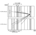
- FIG. 4 is a diagram illustrating an example of multiple simultaneous transmissions of PSFCHs according to the first embodiment of the present disclosure
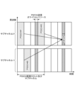
- FIG. 4 is a diagram illustrating an example of transmission of a second PSFCH according to the second embodiment of the present disclosure
- FIG. FIG. 12 is a diagram illustrating an example of transmission of a first PSFCH and a second PSFCH according to the third embodiment of the present disclosure
- FIG. 12 is a diagram illustrating an example of resource regions of the second PSFCH according to the third embodiment of the present disclosure
- FIG. FIG. 12 is a diagram illustrating another example of the resource region of the second PSFCH according to the third embodiment of the present disclosure
- FIG. FIG. 12 is a diagram illustrating another example of the resource region of the second PSFCH according to the third embodiment of the present disclosure
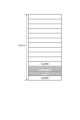
- FIG. FIG. 12 is a diagram illustrating an example of the format of the second PSFCH according to the third embodiment of the present disclosure
- FIG. FIG. 12 is a diagram showing another example of the format of the second PSFCH according to the third embodiment of the present disclosure
- FIG. 10 is a diagram illustrating an example of a semi-static HARQ codebook on the second PSFCH according to the third embodiment of the present disclosure
- FIG. 12 is a diagram illustrating an example of transmission of the second PSFCH according to the third embodiment of the present disclosure
- FIG. 10 is a diagram illustrating an example of a dynamic HARQ codebook on the second PSFCH according to the third embodiment of the present disclosure
- FIG. 12 is a diagram illustrating an example of transmission of the second PSFCH according to the third embodiment of the present disclosure
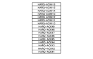
- FIG. 10 is a diagram illustrating an example of a one-shot HARQ codebook on the second PSFCH according to the third embodiment of the present disclosure
- FIG. 12 is a diagram illustrating an example of transmission of the second PSFCH according to the third embodiment of the present disclosure
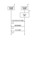
- FIG. 11 is a diagram illustrating an example of a communication method according to a third embodiment of the present disclosure
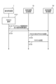
- FIG. FIG. 12 is a diagram showing another example of the communication method according to the third embodiment of the present disclosure
- FIG. FIG. 12 is a diagram showing another example of the communication method according to the third embodiment of the present disclosure
- the radio communication system includes at least a base station device 1 and a terminal device 2.
- the base station device 1 can accommodate a plurality of terminal devices.
- the base station device 1 can be connected to other base station devices by means of the X2 interface.
- the base station apparatus 1 can be connected to an EPC (Evolved Packet Core) by means of an S1 interface.
- the base station apparatus 1 can connect to an MME (Mobility Management Entity) by means of an S1-MME interface, and can be connected to an S-GW (Serving Gateway) by means of an S1-U interface.
- the S1 interface supports many-to-many connections between the MME and/or S-GW and the base station apparatus 1.
- the base station apparatus 1 and the terminal apparatus 2 each support LTE and/or NR.
- FIG. 1 is a diagram showing an overview of sidelink communication according to an embodiment of the present disclosure.
- One use case is a case where two or more terminal devices 2 exist inside a cell 3 configured by the base station device 1 and sidelink communication is performed.
- at least one terminal device 2 among two or more terminal devices 2 exists inside the cell 3 configured by the base station device 1, and the other terminal device 2 exists outside the cell 3.
- the terminal device 2 existing inside the cell 3 can perform relaying between the base station device 1 and the terminal device 2 existing outside the cell 3 by communicating with the base station device 1 .
- the fact that the terminal device 2 exists inside the cell 3 means that the quality of the downlink signal received by the terminal device 2 from the base station device 1 is equal to or higher than a predetermined standard.
- the fact that the terminal device 2 exists inside the cell 3 is a state in which the terminal device 2 can decode a predetermined downlink channel received from the base station apparatus 1 with a predetermined probability or more.
- the presence of the terminal device 2 outside the cell 3 means that the quality of the downlink signal received by the terminal device 2 from the base station apparatus 1 is below a predetermined standard.
- the fact that the terminal device 2 exists outside the cell 3 means that the terminal device 2 cannot decode a predetermined downlink channel received from the base station apparatus 1 with a predetermined probability or more.
- first terminal device two terminal devices that transmit and receive by sidelink communication
- second terminal device two terminal devices that transmit and receive by sidelink communication
- a terminal device that receives information about sidelink communication from a base station device and transmits a sidelink control channel is called a first terminal device, and other terminal devices are called second terminal devices.
- FIG. 2 is a schematic block diagram showing the configuration of the base station device 1 according to the embodiment of the present disclosure.
- base station apparatus 1 includes upper layer processing section 101 , control section 103 , receiving section 105 , transmitting section 107 , and transmitting/receiving antenna 109 .
- Reception section 105 includes decoding section 1051 , demodulation section 1053 , demultiplexing section 1055 , radio reception section 1057 and channel measurement section 1059 .
- the transmitting section 107 includes an encoding section 1071 , a modulating section 1073 , a multiplexing section 1075 , a radio transmitting section 1077 and a downlink reference signal generating section 1079 .
- the base station device 1 can support one or more RATs. Some or all of the units included in the base station apparatus 1 shown in FIG. 2 can be individually configured according to the RAT. For example, the receiving unit 105 and the transmitting unit 107 are individually configured for LTE and NR. Also, in the NR cell, some or all of the units included in the base station apparatus 1 shown in FIG. 2 can be individually configured according to the parameter set regarding the transmission signal. For example, in a given NR cell, radio receiver 1057 and radio transmitter 1077 can be individually configured according to parameter sets for transmitted signals.
- the upper layer processing unit 101 includes a medium access control (MAC) layer, a packet data convergence protocol (PDCP) layer, a radio link control (RLC) layer, a radio resource control (RRC :Radio Resource Control) layer processing. Further, upper layer processing section 101 generates control information for controlling receiving section 105 and transmitting section 107 and outputs the control information to control section 103 .
- MAC medium access control
- PDCP packet data convergence protocol
- RLC radio link control
- RRC Radio Resource Control
- the control unit 103 controls the receiving unit 105 and the transmitting unit 107 based on the control information from the upper layer processing unit 101 .
- the control unit 103 generates control information for the upper layer processing unit 101 and outputs the control information to the upper layer processing unit 101 .
- Control section 103 receives the decoded signal from decoding section 1051 and the channel estimation result from channel measurement section 1059 .
- Control section 103 outputs a signal to be encoded to encoding section 1071 .
- Control section 103 is used to control all or part of base station apparatus 1 .
- the upper layer processing unit 101 performs processing and management related to RAT control, radio resource control, subframe configuration, scheduling control, and/or CSI reporting control. Processing and management in the upper layer processing unit 101 are performed for each terminal device or commonly for terminal devices connected to the base station device.
- the processing and management in upper layer processing section 101 may be performed only by upper layer processing section 101, or may be obtained from an upper node or another base station apparatus. Also, the processing and management in the upper layer processing unit 101 may be performed individually according to the RAT. For example, the upper layer processing unit 101 separately performs processing and management in LTE and processing and management in NR.
- RAT management is performed.
- management for LTE and/or management for NR is performed.
- Management for NR includes configuration and processing of parameter sets for transmission signals in NR cells.
- Radio resource control in the upper layer processing unit 101 generates and/or manages downlink data (transport blocks), system information, RRC messages (RRC parameters), and/or MAC control elements (CE: Control Elements). done.
- subframe setting in higher layer processing section 101 management of subframe setting, subframe pattern setting, uplink-downlink setting, uplink reference UL-DL setting, and/or downlink reference UL-DL setting is performed.
- the subframe setting in upper layer processing section 101 is also called base station subframe setting.
- the subframe setting in the upper layer processing section 101 can be determined based on the uplink traffic volume and the downlink traffic volume.
- the subframe setting in higher layer processing section 101 can be determined based on the scheduling results of scheduling control in higher layer processing section 101 .
- the scheduling control in the upper layer processing unit 101 based on the received channel state information and the propagation path estimation value and channel quality input from the channel measurement unit 1059, the frequencies and subframes for allocating the physical channels, the physical channel Coding rate, modulation scheme, transmission power, etc. are determined. For example, the control unit 103 generates control information (DCI format) based on the scheduling result of scheduling control in the upper layer processing unit 101 .
- DCI format control information
- the CSI reporting of the terminal device 2 is controlled by the CSI reporting control in the upper layer processing section 101 .
- settings related to CSI reference resources to be assumed for calculating CSI in the terminal device 2 are controlled.
- Receiving section 105 receives a signal transmitted from terminal device 2 via transmitting/receiving antenna 109 under the control of control section 103, performs reception processing such as separation, demodulation, and decoding, and outputs the received information. Output to the control unit 103 . Note that the reception process in the reception unit 105 is performed based on a preset setting or a setting notified to the terminal device 2 by the base station device 1 .
- the radio receiving unit 1057 converts the uplink signal received via the transmitting/receiving antenna 109 into an intermediate frequency (down-converts), removes unnecessary frequency components, and maintains the signal level appropriately.
- Amplification level control, quadrature demodulation based on the in-phase and quadrature components of the received signal, analog signal to digital signal conversion, guard interval (GI) removal, and/or fast Fourier transform (FFT: Fast Fourier Transform) is used to extract the frequency domain signal.
- the demultiplexing section 1055 separates an uplink channel such as PUCCH or PUSCH and/or an uplink reference signal from the signal input from the radio receiving section 1057 .
- Demultiplexing section 1055 outputs the uplink reference signal to channel measurement section 1059 .
- Demultiplexing section 1055 performs propagation path compensation for the uplink channel from the propagation path estimation value input from channel measurement section 1059 .
- the demodulator 1053 demodulates the modulation symbols of the uplink channel using a modulation scheme such as BPSK (Binary Phase Shift Keying), QPSK (Quadrature Phase shift Keying), 16QAM (Quadrature Amplitude Modulation), 64QAM, 256QAM, etc. is demodulated.
- Demodulator 1053 separates and demodulates the MIMO-multiplexed uplink channel.
- the decoding unit 1051 performs decoding processing on the demodulated coded bits of the uplink channel.
- the decoded uplink data and/or uplink control information is output to control section 103 .
- Decoding section 1051 performs decoding processing on PUSCH for each transport block.
- Channel measuring section 1059 measures the channel estimation value and/or channel quality from the uplink reference signal input from demultiplexing section 1055 and outputs the results to demultiplexing section 1055 and/or control section 103 .
- the channel measurement unit 1059 uses UL-DMRS to measure a channel estimation value for performing channel compensation for PUCCH or PUSCH, and uses SRS to measure uplink channel quality.
- the transmission section 107 performs transmission processing such as encoding, modulation and multiplexing on the downlink control information and downlink data input from the upper layer processing section 101 under the control of the control section 103 .
- the transmitting section 107 generates and multiplexes PHICH, PDCCH, EPDCCH, PDSCH, and downlink reference signals to generate transmission signals.
- the transmission process in the transmitting unit 107 is based on a predetermined setting, a setting notified to the terminal device 2 by the base station apparatus 1, or a setting notified through the PDCCH or EPDCCH transmitted in the same subframe. done.
- Coding section 1071 converts the HARQ indicator (HARQ-ACK, ACK/NACK), downlink control information, and downlink data input from control section 103 to block coding, convolutional coding, turbo coding, or the like. Encoding is performed using a predetermined encoding method.
- Modulating section 1073 modulates the coded bits input from coding section 1071 using a predetermined modulation scheme such as BPSK, QPSK, 16QAM, 64QAM, and 256QAM.
- the downlink reference signal generation section 1079 generates a downlink reference signal based on a physical cell identifier (PCI), RRC parameters set in the terminal device 2, and the like.
- the multiplexing section 1075 multiplexes the modulation symbols of each channel and the downlink reference signal, and arranges them in predetermined resource elements.
- the radio transmission unit 1077 converts the signal from the multiplexing unit 1075 into a time domain signal by inverse fast Fourier transform (IFFT), adds a guard interval, generates a baseband digital signal, Converts to analog signals, quadrature modulation, converts intermediate frequency signals to high frequency signals (up-convert), removes unnecessary frequency components, amplifies power, and other processes to generate transmission signals .
- IFFT inverse fast Fourier transform
- a transmission signal output from radio transmission section 1077 is transmitted from transmission/reception antenna 109 .
- FIG. 3 is a schematic block diagram showing the configuration of the terminal device 2 according to the embodiment of the present disclosure.
- the terminal device 2 includes an upper layer processing section 201 , a control section 203 , a receiving section 205 , a transmitting section 207 and a transmitting/receiving antenna 209 .
- Receiving section 205 includes decoding section 2051 , demodulating section 2053 , demultiplexing section 2055 , radio receiving section 2057 and channel measuring section 2059 .
- the transmitting section 207 includes an encoding section 2071 , a modulating section 2073 , a multiplexing section 2075 , a radio transmitting section 2077 and an uplink reference signal generating section 2079 .
- the terminal device 2 can support one or more RATs.
- a part or all of each unit included in the terminal device 2 shown in FIG. 3 can be individually configured according to the RAT.
- the receiving unit 205 and the transmitting unit 207 are individually configured for LTE and NR.
- some or all of the units included in the terminal device 2 shown in FIG. 3 can be individually configured according to the parameter set regarding the transmission signal.
- radio receiver 2057 and radio transmitter 2077 can be individually configured according to a parameter set for transmission signals.
- the upper layer processing section 201 outputs uplink data (transport blocks) to the control section 203 .
- the upper layer processing unit 201 includes a medium access control (MAC) layer, a packet data convergence protocol (PDCP) layer, a radio link control (RLC) layer, a radio resource control (RRC :Radio Resource Control) layer processing.
- the upper layer processing unit 201 also generates control information for controlling the receiving unit 205 and the transmitting unit 207 and outputs the control information to the control unit 203 .
- MAC medium access control
- PDCP packet data convergence protocol
- RLC radio link control
- RRC Radio Resource Control
- the control unit 203 controls the receiving unit 205 and the transmitting unit 207 based on the control information from the upper layer processing unit 201 .
- the control unit 203 generates control information for the upper layer processing unit 201 and outputs the control information to the upper layer processing unit 201 .
- Control section 203 receives the decoded signal from decoding section 2051 and the channel estimation result from channel measurement section 2059 .
- Control section 203 outputs a signal to be encoded to encoding section 2071 .
- the control unit 203 may be used to control all or part of the terminal device 2 .
- the upper layer processing unit 201 performs processing and management related to RAT control, radio resource control, subframe configuration, scheduling control, and/or CSI reporting control. Processing and management in upper layer processing section 201 are performed based on settings defined in advance and/or settings based on control information set or notified from base station apparatus 1 . For example, control information from the base station apparatus 1 includes RRC parameters, MAC control elements or DCI. Also, the processing and management in the upper layer processing unit 201 may be performed individually according to the RAT. For example, the upper layer processing unit 201 separately performs processing and management in LTE and processing and management in NR.
- RAT management is performed. For example, in RAT control, management for LTE and/or management for NR is performed. Management for NR includes configuration and processing of parameter sets for transmission signals in NR cells.
- Radio resource control in the upper layer processing unit 201 setting information in the own device is managed.
- Radio resource control in the upper layer processing unit 201 includes generation and/or management of uplink data (transport blocks), system information, RRC messages (RRC parameters), and/or MAC control elements (CE: Control Elements). done.
- the subframe setting in the upper layer processing section 201 the subframe setting in the base station device 1 and/or a base station device different from the base station device 1 is managed.
- the subframe configuration includes uplink or downlink configuration, subframe pattern configuration, uplink-downlink configuration, uplink reference UL-DL configuration and/or downlink reference UL-DL configuration for the subframe.
- the subframe setting in upper layer processing section 201 is also called terminal subframe setting.
- control information for controlling scheduling for receiving section 205 and transmitting section 207 is generated based on DCI (scheduling information) from base station apparatus 1 .
- control regarding CSI reporting to the base station device 1 is performed.
- control regarding CSI reporting to the base station device 1 is performed.
- settings related to CSI reference resources assumed for calculating CSI in channel measurement section 2059 are controlled.
- CSI reporting control controls the resources (timing) used to report CSI based on DCI and/or RRC parameters.
- Receiving section 205 receives a signal transmitted from base station apparatus 1 via transmitting/receiving antenna 209 under the control of control section 203, performs reception processing such as separation, demodulation, and decoding, and receives the processed information. is output to the control unit 203 . Note that the reception processing in the reception section 205 is performed based on a preset setting or notification or setting from the base station apparatus 1 .
- the radio reception unit 2057 converts the uplink signal received via the transmission/reception antenna 209 into an intermediate frequency (down-converts), removes unnecessary frequency components, and maintains the signal level appropriately.
- Amplification level control, quadrature demodulation based on the in-phase and quadrature components of the received signal, analog signal to digital signal conversion, guard interval (GI) removal, and/or fast Fourier transform (FFT: Fast Fourier Transform) is used to extract frequency domain signals.
- the demultiplexing section 2055 separates downlink channels such as PHICH, PDCCH, EPDCCH or PDSCH, downlink synchronization signals and/or downlink reference signals from the signal input from the radio receiving section 2057 .
- the demultiplexing section 2055 outputs the downlink reference signal to the channel measuring section 2059 .
- the demultiplexing unit 2055 performs channel compensation for the downlink channel from the channel estimation value input from the channel measuring unit 2059 .
- the demodulator 2053 demodulates the received signal using a modulation scheme such as BPSK, QPSK, 16QAM, 64QAM, 256QAM, etc. for the modulation symbols of the downlink channel.
- the demodulator 2053 separates and demodulates the MIMO-multiplexed downlink channels.
- the decoding unit 2051 performs decoding processing on the coded bits of the demodulated downlink channel.
- the decoded downlink data and/or downlink control information is output to control section 203 .
- the decoding unit 2051 performs decoding processing on the PDSCH for each transport block.
- the channel measuring section 2059 measures the propagation path estimation value and/or channel quality from the downlink reference signal input from the demultiplexing section 2055 and outputs to the demultiplexing section 2055 and/or the control section 203 .
- the downlink reference signal that the channel measuring section 2059 uses for measurement may be determined based on at least the transmission mode set by the RRC parameters and/or other RRC parameters.
- DL-DMRS measures channel estimates for performing channel compensation for PDSCH or EPDCCH.
- the CRS measures channel estimates for performing channel compensation for PDCCH or PDSCH and/or downlink channels for reporting CSI.
- CSI-RS measures channels in the downlink for reporting CSI.
- Channel measurement section 2059 calculates RSRP (Reference Signal Received Power) and/or RSRQ (Reference Signal Received Quality) based on the CRS, CSI-RS or detection signal, and outputs them to upper layer processing section 201 .
- RSRP Reference Signal Received Power
- RSRQ Reference Signal Received Quality
- the transmission section 207 performs transmission processing such as encoding, modulation and multiplexing on the uplink control information and uplink data input from the upper layer processing section 201 under the control of the control section 203 .
- the transmitting section 207 generates and multiplexes an uplink channel such as PUSCH or PUCCH and/or an uplink reference signal to generate a transmission signal.
- the transmission process in the transmission section 207 is performed based on a preset setting or based on the setting or notification from the base station apparatus 1 .
- Coding section 2071 converts the HARQ indicator (HARQ-ACK, ACK/NACK), uplink control information, and uplink data input from control section 203 to block coding, convolutional coding, turbo coding, or the like. Encoding is performed using a predetermined encoding method.
- Modulation section 2073 modulates the coded bits input from coding section 2071 using a predetermined modulation scheme such as BPSK, QPSK, 16QAM, 64QAM, and 256QAM.
- the uplink reference signal generating section 2079 generates uplink reference signals based on the RRC parameters set in the terminal device 2 and the like.
- the multiplexing section 2075 multiplexes the modulation symbols of each channel and the uplink reference signal and arranges them in predetermined resource elements.
- the radio transmission unit 2077 converts the signal from the multiplexing unit 2075 into a time domain signal by inverse fast Fourier transform (IFFT), adds a guard interval, generates a baseband digital signal, Converts to analog signals, quadrature modulation, converts intermediate frequency signals to high frequency signals (upconvert), removes excess frequency components, amplifies power, and other processes to generate transmission signals .
- IFFT inverse fast Fourier transform
- a transmission signal output from the radio transmission section 2077 is transmitted from the transmission/reception antenna 209 .
- the base station device 1 is an example of the communication device described in the claims.
- the terminal device 2 is an example of a communication device described in claims.
- Sidelink communication is direct communication between a terminal device and a different terminal device.
- candidates for time and frequency resources used for transmission and reception of the sidelink called a resource pool, are set in the terminal device.
- a resource for sidelink transmission/reception is selected from the resource pool, and sidelink communication is performed. Since sidelink communication is performed using uplink resources (uplink subframes, uplink component carriers), resource pools are also set to uplink subframes or uplink component carriers.
- the sidelink physical channel includes PSCCH (Physical Sidelink Control Channel), PSSCH (Physical Sidelink Shared Channel), PSFCH (Physical Sidelink Feedback Channel), and the like.
- PSCCH Physical Sidelink Control Channel
- PSSCH Physical Sidelink Shared Channel
- PSFCH Physical Sidelink Feedback Channel
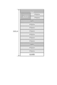
- FIG. 4 shows an example of a sidelink frame in which the PSCCH has a two-symbol configuration. Also, the frame in FIG. 4 represents an example in which two DMRS symbols are allocated and no PSFCH is allocated.
- FIG. 5 shows an example of a sidelink frame in which the PSCCH has a 3-symbol configuration. Also, the frame in FIG. 5 represents an example in which two DMRS symbols are allocated and a PSFCH is allocated.
- the PSCCH is used to transmit sidelink control information (SCI: Sidelink Control Information).
- SCI Sidelink Control Information
- This PSCCH is composed of 2 or 3 symbols. Mapping of information bits of sidelink control information is defined as SCI format.
- the sidelink control information includes a sidelink grant (sidelink assignment). This sidelink grant is used for PSSCH scheduling.
- the PSSCH is used to transmit sidelink data (SL-SCH: Sidelink Shared Channel). Note that the PSSCH may also be used to transmit higher layer control information.
- SL-SCH Sidelink Shared Channel
- the PSFCH is used to feed back the HARQ response (HARQ-ACK, ACK/NACK) to the PSSCH decoding result to the transmitting terminal apparatus.
- PSFCH is placed in the 13th symbol.
- the PSFCH may not be allocated resources in all slots. In that case, resources can also be utilized as PSSCH.
- AGC symbols are included in the sidelink frame configuration. This AGC symbol may be used for AGC (Automatic Gain Control) of the receiving terminal device.
- the AGC symbol is placed in the first symbol of transmission. Specifically, the AGC symbol is arranged in the 1st symbol when transmitting the PSSCH, and in the 12th symbol when transmitting the PSFCH.
- An AGC symbol is generated by copying the second symbol of transmission. That is, in side link transmission, the first and second symbols of transmission are the same signal.
- a GUARD symbol is included in the sidelink frame structure.
- switching between transmission and reception is performed using a guard symbol (guard time).
- a guard symbol is placed at the 14th symbol.
- guard symbols are also arranged in the 11th symbol.
- a resource pool is configured from the base station apparatus to the terminal apparatus by SIB or dedicated RRC message. Alternatively, it is set by information about a resource pool preset in the terminal device.
- the time resource pool is indicated by period information, offset information, and subframe bitmap information.
- a resource pool of frequencies is indicated by a resource block start position, a resource block end position, and the number of consecutive resource blocks.
- FIG. 6 is a diagram showing a configuration example of a sidelink resource pool according to the embodiment of the present disclosure.
- a resource pool (sidelink resource pool) is set as a resource used for PSSCH transmission and PSSCH reception.
- a resource pool On the frequency axis, a resource pool consists of one or more consecutive subchannels. Also, a sub-channel is composed of one or more consecutive physical resource blocks (PRB: Physical Resource Block). The number of sub-channels and the size of the sub-channels are set by higher layer parameters.
- PRB Physical Resource Block
- the slots set as resource pools are indicated by bitmaps.
- Each bit in the bitmap corresponds to a slot that can be set as a sidelink resource pool. For example, if the bit value indicates a value of '1', the corresponding slot is configured as a resource pool, and if the bit value indicates a value of '0', the corresponding slot is not configured as a resource pool.
- the length of this bitmap is set by higher layers.
- the slots set as resource pools are determined according to predetermined conditions in addition to being indicated by the bitmap. For example, slots containing S-SS/PSBCH blocks are not configured as resource pools. Also, slots that semi-statically do not include a predetermined number of uplink symbols are not set as resource pools. Also, reserved slots are not configured as resource pools.
- the device that sets the resource pool may be other than the base station device.
- Devices other than the base station device include, for example, a representative terminal device (primary terminal device, master terminal device), and the like.
- the base station apparatus allocates resources for transmission of the sidelink physical channel (PSCCH and PSSCH) "resource allocation mode 1 (Sidelink Resource allocation mode 1)" method, and the terminal There is a method of "Sidelink Resource allocation mode 2" in which the device itself performs sensing and selects resources for transmission of the sidelink physical channel.
- Resource allocation mode 1 In resource allocation mode 1, when a transmission packet is generated in the terminal device, the resource to be used for transmission of the packet is allocated by the base station device from the resource pool.
- resource allocation mode 1 resources used for sidelink transmission are designated by dynamic grant or RRC signaling sent from the base station apparatus.
- dynamic grant configured grant type 1 and configured grant type 2 are supported for PSSCH and PSCCH transmissions.
- PSSCH transmission is scheduled by DCI format 3_0.
- resources for PSSCH transmission are allocated by RRC signaling.
- sidelink configured grant type 2 configured grant is activated by DCI format 3_0, and PSSCH transmission is performed using resources specified by RRC signaling.
- resource allocation mode 1 resource allocation is performed by the base station apparatus each time a transmission packet is generated, so the frequency of collisions between sidelink communications can be reduced. On the other hand, much signaling overhead is required between the base station apparatus and the terminal apparatus.
- Resource allocation mode 2 In resource allocation mode 2, resource pools are allocated in advance by the base station apparatus and the network.
- Resource allocation mode 2 the following four types of resource allocation modes are further classified.
- the terminal device In resource allocation mode 2, the terminal device, and the measurement result of the interference pattern in the sensing window, based on the side link resource reservation status in the sensing window, selection of side link resources in the resource selection window, future side Link resource reservations can be made.
- the terminal device can select and reserve sidelink resources that can be used for transmission of the packet, that is, sidelink resources that are predicted not to be used for transmission of other packets. becomes.
- Resource allocation mode 2 when a packet is generated in a terminal device, the terminal device autonomously selects a sidelink resource to be used for transmission of the packet from the resource pool.
- a terminal device that transmits a packet first performs sensing to discover sidelink resources to be used for transmission of the packet from within the resource pool. Then, the terminal device selects a sidelink resource from within the resource pool based on the sensing result. Then, the terminal device transmits packets using the selected sidelink resource. Also, at this time, the terminal device reserves a sidelink resource to be used for subsequent packet transmission, if necessary.
- This resource allocation mode 2(a) is a semi-persistent method in which resources are selected for multiple sidelink transmissions with different transport blocks, and a resource is selected each time for sidelink transmissions of each transport. It can be applied to both dynamic methods.
- resource allocation mode 2 In resource allocation mode 2(c), a sidelink transmission pattern is set in the terminal device.
- the terminal device selects sidelink resources to be used for transmission according to the set sidelink transmission pattern.
- a sidelink transmission pattern is defined by the size, position and number of resources in time and frequency.
- Multiple sidelink transmission patterns can be set. When only one sidelink transmission pattern is set, the terminal device does not perform sensing. On the other hand, when a plurality of sidelink transmission patterns are set, the terminal device performs sensing and selects a sidelink transmission pattern based on the sensing result.
- one or more sidelink transmission patterns defined in each sidelink resource pool are preset. Also, in in-coverage operation, one or more sidelink transmission patterns defined in each sidelink resource pool are set from the base station apparatus.
- FIG. 7 is a diagram illustrating an example of resource allocation mode 2(d) according to an embodiment of the present disclosure.
- Resource allocation mode 2(d) is applied in group-based sidelink communication composed of three or more terminal devices.
- a representative terminal device primary terminal device
- the representative terminal device reports information of other terminal devices (secondary terminal devices or member terminal devices) in the group to the base station device.
- the base station device 1 provides resource pool settings and resource settings for each terminal device in the group via the representative terminal device.
- the member terminal device does not require direct connection with the base station device, so the signal overhead of the Uu link (communication link between the base station device and the terminal device) can be reduced.
- the terminal device that can be the representative terminal device and the functions that can be provided are determined depending on the capabilities of the terminal device.
- the representative terminal device 2a can provide predetermined assist information to member terminal devices.
- assist information include resource pool settings, information about collisions, COT sharing information, CSI, information about congestion levels, and the like.
- sensing in side link In resource allocation mode 2, sensing procedures are supported. For sidelink sensing, SCI decoding from other terminal devices and/or sidelink resource measurements are used.
- the terminal device In sensing by SCI decoding, the terminal device acquires information on the sidelink resource to be used included in the SCI transmitted from the other terminal device. Based on the SCI information, the terminal device determines sidelink resources to be used for transmission while avoiding resources that are scheduled to be used by other terminal devices.
- the terminal In sensing by sidelink resource measurement, the terminal performs L1 (Layer 1) sidelink RSRP measurement based on the sidelink DMRS.
- L1 Layer 1
- the terminal device recognizes that the measured sidelink resource is used for transmission by another terminal device, avoids the sidelink resource, and uses the sidelink resource for transmission. decide.
- the terminal device selects or reselects sidelink resources based on the results of the above sensing procedure.
- PSFCH format 0 For the PSFCH, one PSFCH format (PSFCH format 0) is defined.
- PSFCH format 0 can contain up to 1 bit of ACK (acknowledgement) or NACK (negative acknowledgment).
- a resource on which the PSFCH is transmitted is referred to as a PSFCH transmission occasion resource.
- the slot in which the PSFCH is arranged is determined by the slot period of the PSFCH.
- the slot period of PSFCH is set from 1, 2, or 4.
- a PSFCH of PSFCH format 0 consists of 1 symbol and 1 resource block.
- the PSFCH of PSFCH format 0 is arranged at the 13th symbol in the slot.
- the PSFCH is located in resource blocks specified by the RRC parameter sl-PSFCH-RB-Set. Furthermore, in PSFCH format 0, up to 6 different PSFCHs can be placed on the same time/frequency resource by cyclic shift.
- the PSFCH is transmitted using the most recent PSFCH transmission occasion resource after the time gap from the slot in which the corresponding PSSCH was transmitted.
- the time gap is set by the RRC parameter sl-MinTimeGapPSFCH and is 2 slots or 3 slots.
- FIG. 8 is a diagram illustrating an example of the relationship between PSSCH and PSFCH resources according to an embodiment of the present disclosure. This figure shows the relationship between the PSSCH and PSFCH resources when the PSFCH has a slot period of 2 slots and a time gap of 2 slots.
- the value of the PSFCH resource block and sequence cyclic shift is determined based on the source ID (identifier of the transmitting terminal device). Furthermore, in the case of group casting of ACK/NACK feedback, an offset for distinguishing PSFCH resources of multiple receiving terminal apparatuses is set from higher layers.
- a PSFCH of PSFCH format 0 indicates ACK or NACK depending on the cyclic shift value. Specifically, when the cyclic shift value is compared with the reference value, NACK is indicated when the value is "0", and ACK is indicated when the value is "6".
- the PSFCH supports NACK-only HARQ-ACK feedback in groupcast. If a NACK-only group cast is specified as the cast type, the PSFCH is transmitted on the corresponding resource in the case of NACK, and the PSFCH is not transmitted in the resource in the case of ACK.
- Transmission of the PSFCH can be disabled by RRC configuration or SCI indication. Transmission of the PSFCH can be disabled by setting the slot period to the value '0' in the RRC configuration or by indicating disabled by the HARQ feedback enabled/disabled indicator included in the SCI.
- the transmission power of one PSFCH is calculated by the following formula.
- P PSFCH,one P O,PSFCH +10log 10 (2 ⁇ )+ ⁇ PSFCH ⁇ PL[dBm]
- PO,PSFCH represents the value of the upper layer parameter dl-P0-PSFCH.
- ⁇ PSFCH represents the value of the upper layer parameter dl-Alpha-PSFCH, and has a value of "1" when dl-Alpha-PSFCH is not given.
- PL represents downlink path loss.
- ⁇ represents the SCS setting.
- the terminal device selects the PSFCH in descending order of the priority of the corresponding PSSCH within a range not exceeding the maximum transmission power Pmax. , the transmission of the PSFCH with the higher priority of the corresponding PSSCH is dropped.
- the terminal device selects the PSFCH having the highest priority among the PSFCHs. based on which transmit or receive operation is determined. Specifically, when the PSFCH with the highest priority is the PSFCH that is scheduled to be transmitted, the terminal device performs transmission in the PSFCH transmission occasion, and the PSFCH with the highest priority is the PSFCH that is scheduled to be received. If so, it receives on the PSFCH transmission occasion.
- the terminal device When the number of scheduled PSFCH transmissions in the same PSFCH transmission occasion is greater than the maximum number of PSFCH simultaneous transmissions of the terminal device, the terminal device transmits the PSFCHs in descending order of priority within a range that does not exceed the maximum number of PSFCH simultaneous transmissions of the terminal device. select.
- the priority is the value indicated by the priority field included in SCI format 1-A corresponding to the PSFCH transmission occasion.
- Carrier aggregation is a technology that expands the frequency bandwidth by bundling and simultaneously using multiple frequency bands (cells and carriers).
- FIG. 9 is a diagram illustrating an example of sidelink carrier aggregation according to an embodiment of the present disclosure.
- two cells are set for PSSCH transmission.
- two transceivers By providing two transceivers to correspond to the transmission and reception of each cell, it becomes possible to transmit the PSSCH simultaneously from each cell.
- two PSSCHs are transmitted simultaneously in the 1st and 6th slots.
- Carrier aggregation can improve throughput.
- configuration of PSFCH capable of carrying multiple sidelink HARQ-ACK (SL-HARQ-ACK) and sidelink HARQ-ACK (SL-HARQ-ACK) Provide feedback control techniques.
- the first embodiment of the present disclosure describes an example in which SL-HARQ-ACK generated in each cell is transmitted on the PSFCH of each cell.
- This first embodiment in other words, is an embodiment in which the SL-HARQ-ACK is not sent in a different cell than the cell in which the corresponding PSSCH was sent.
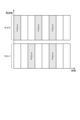
- FIG. 10 is a diagram illustrating an example of multiple simultaneous transmissions of PSFCHs according to the first embodiment of the present disclosure.
- the figure shows an example in which two cells are configured and PSSCH transmissions occur simultaneously in the 1st and 4th slots.
- two SL-HARQ-ACKs corresponding to the first PSSCH are sent simultaneously on the same cell in the third slot on the PSFCH.
- two SL-HARQ-ACKs corresponding to the 4th PSSCH are sent simultaneously on the PSFCH in the same cell in the 7th slot.
- the first embodiment since it is possible to operate independently in each cell, the first embodiment is applied to a terminal device capable of simultaneously transmitting a plurality of first PSFCHs. be able to.
- SL-HARQ-ACK generated in each cell is transmitted on the second PSFCH of one cell.
- the SL-HARQ-ACK can be sent in a different cell than the cell in which the corresponding PSSCH was sent.
- the PSFCH transmitted in the conventional PSFCH format (PSFCH format 0) is called the first PSFCH
- the PSFCH transmitted in the new PSFCH format e.g. PSFCH format 1
- the second PSFCH is a PSFCH that may contain multiple HARQ-ACKs.
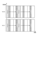
- FIG. 11 is a diagram illustrating an example of transmission of the second PSFCH according to the second embodiment of the present disclosure. Similar to FIG. 10, this figure shows an example in which two cells are set and PSSCH transmissions occur simultaneously in the first and fourth slots. Unlike the first embodiment, the SL-HARQ-ACK corresponding to the cell 2 PSSCH transmitted in the first slot is transmitted in the cell 1 PSFCH. Also, the SL-HARQ-ACK corresponding to the cell 1 PSSCH transmitted in the fourth slot is transmitted in the cell 2 PSFCH.
- multiple SL-HARQ-ACKs can be transmitted in one cell. Therefore, it is possible to realize PSFCH transmission with low power consumption and different transmission and reception operations in a plurality of cells.
- the third embodiment is an embodiment in which the simultaneous transmission of the PSFCH according to the first embodiment and the second PSFCH transmission according to the second embodiment are applied in combination.
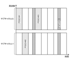
- FIG. 12 is a diagram illustrating an example of transmission of the first PSFCH and the second PSFCH according to the third embodiment of the present disclosure.
- three cells are set, and PSSCH transmission occurs simultaneously in each cell.
- the SL-HARQ-ACK corresponding to the PSSCH of cell 1 is transmitted on the PSFCH of cell 1
- the two SL-HARQ-ACKs corresponding to the PSSCHs of cell 2 and cell 3 are transmitted on the cell 3 PSFCH.
- the two SL-HARQ-ACKs corresponding to the PSSCHs of cell 1 and cell 3 are transmitted on the PSFCH of cell 1, and the SL-HARQ-ACK corresponding to the PSSCH of cell 2 is transmitted. is transmitted on the PSFCH of cell 2.
- the third embodiment enables operation that compensates for the shortcomings of the first and second embodiments.
- the resource region of the second PSFCH is preferably configured in a resource region different from that of the first PSFCH.
- An example of the resource region of the second PSFCH is listed below.
- the resource region of the second PSFCH can be arranged by frequency division multiplexing (FDM) with the resource region of the first PSFCH in the same resource pool.
- FDM frequency division multiplexing
- FIG. 13 is a diagram illustrating an example of resource regions of the second PSFCH according to the third embodiment of the present disclosure.
- the second PSFCH is arranged in the same symbol as the first PSFCH, and is assigned a resource block different from that of the first PSFCH.
- the resource blocks that can be allocated by the second PSFCH may be all resource blocks other than the resource blocks allocated by the first PSFCH, or resource blocks may be designated by higher layers.
- the resource region of the second PSFCH can be arranged by time division multiplexing (TDM) with the resource region of the first PSFCH in the same resource pool.
- TDM time division multiplexing
- FIG. 14 is a diagram showing another example of the second PSFCH resource region according to the third embodiment of the present disclosure.
- the second PSFCH is arranged in a different symbol than the first PSFCH.
- the second PSFCH may use some or all resource blocks of one subchannel.
- the second PSFCH transmission can avoid collisions by sensing from other terminals.
- the slot in which the second PSFCH is allocated may be reserved by reservation information. This can prevent collisions with PSSCH transmissions.
- the resource region of the second PSFCH can be placed in a resource pool different from that of the first PSFCH.
- Different resource pools may be different resource pools in the same cell or resource pools between different cells.
- FIG. 15 is a diagram showing another example of the second PSFCH resource region according to the third embodiment of the present disclosure.
- a resource region for the first PSFCH is configured in cell 1 and a resource region for the second PSFCH is configured in cell 2 .
- a terminal device that does not support transmission/reception of the second PSFCH (for example, a terminal device prior to 3GPP Release 17) is not connected to cell 2, thereby avoiding collision between the first PSFCH transmission and the second PSFCH transmission. can be prevented.
- PSFCH format 1 An example of a physical channel configuration for the second PSFCH is a different PSFCH format than the first PSFCH.
- the second PSFCH is referred to as PSFCH format 1.
- This second PSFCH format has at least the characteristic of being able to carry more than one SL-HARQ-ACK. That is, the second PSFCH can carry multiple SL-HARQ-ACKs corresponding to the PSSCH transmitted on multiple subchannels, carriers and/or slots on one physical channel. Note that only one SL-HARQ-ACK can also be carried by the second PSFCH format.
- the second PSFCH format may consist of, for example, 2 symbols.
- FIG. 16 is a diagram showing an example of the format of the second PSFCH according to the third embodiment of the present disclosure.
- the second PSFCH in this example has the same symbol configuration as PSFCH format 0, with an AGC symbol at the 12th position, a PSFCH at the 13th position, and guard symbols as transmission/reception gaps at the 11th and 14th positions.
- Some resource elements (REs: Resource Elements) of the PSFCH symbol may include DMRS for demodulating the PSFCH.
- the configuration of the second PSFCH format it can be composed of 4 or more and 13 or less symbols.
- FIG. 17 is a diagram showing another example of the format of the second PSFCH according to the third embodiment of the present disclosure.
- the AGC symbol is arranged in the 1st symbol
- the PSFCH is arranged in the 2nd to 13th symbols
- the 14th is provided with a guard symbol as a transmission/reception gap.
- Some PSFCH symbols may be arranged as DMRSs that demodulate the PSFCH, or DMRSs may be arranged in some resource elements of the PSFCH symbols.
- PSSCH Physical channel configuration 2 of the second PSFCH
- PSSCH can carry SL-HARQ-ACK.
- SL-HARQ-ACK may be encoded together with SL-SCH (Sidelink Shared Channel) carrying sidelink data, may be included in SL-SCH, or may be included in PSSCH. may be placed in the resource element of Also, PSSCH containing SL-HARQ-ACK may not contain SL-SCH.
- SL-SCH Segmentlink Shared Channel
- the PSSCH preferably also contains information about the corresponding PSSCH together with the SL-HARQ-ACK.
- Examples of information about the corresponding PSSCH include corresponding PSSCH resources (slots and subchannels), HARQ process numbers, and the like. This eliminates the need to associate PSSCH and SL-HARQ-ACK with resources, and allows flexible selection of transmission resources.
- the PSSCH may include SL-HARQ-ACKs corresponding to all configured PSSCH HARQ processes. That is, it can also be sent by a one-shot HARQ codebook, which will be described later. In this case, no additional information about the corresponding PSSCH need be included, and control overhead can be reduced. Note that when SL-HARQ-ACK is carried by PSSCH, SL-HARQ-ACK corresponding to HARQ process of PSSCH may not be included, and SL-HARQ-ACK corresponding to the HARQ process is invalid for the terminal device. recognize that there is SL-HARQ-ACKs corresponding to all configured PSSCH HARQ processes. That is, it can also be sent by a one-shot HARQ codebook, which will be described later. In this case, no additional information about the corresponding PSSCH need be included, and control overhead can be reduced. Note that when SL-HARQ-ACK is carried by PSSCH, SL-HARQ-ACK corresponding to HARQ process of PSSCH may not be included, and SL-HARQ
- Transmission resources for the second PSFCH are determined by the transmitting terminal apparatus, the receiving terminal apparatus, another terminal apparatus, or the base station.
- An example of a method for determining transmission resources for the second PSFCH is listed below.
- the transmission resource for the second PSFCH it is set based on the RRC setting.
- this RRC configuration include configuration of the second PSFCH, configuration related to carrier aggregation, and the like.
- the configuration of the second PSFCH includes information on transmission resources for one or more second PSFCHs.
- a second PSFCH resource specific to the receiving terminal device is specified or determined, and when transmission of the second PSFCH is instructed, the resource is used to transmit the second PSFCH. be.
- the parameters specified as the second PSFCH resource are information of the carrier (cell) on which the second PSFCH is transmitted, PRBs (starting and ending PRBs, bitmap, etc.), symbols (starting symbol and symbol length), etc.
- Settings related to carrier aggregation include, for example, information specifying a primary cell (PCell) (or secondary primary cell (PSCell)) in sidelink carrier aggregation.
- PCell primary cell
- PSCell secondary primary cell
- a carrier (cell) that transmits the second PSFCH may be referred to as a PSFCH cell.
- the carrier (cell) on which the PSFCH is transmitted and/or the transmission resources of the PSFCH are included in the SCI. In this case, it is preferable that it is included in the second stage SCI, which facilitates expansion of the SCI bit number.
- a carrier (cell) in which the PSFCH is transmitted and/or a PSFCH transmission resource are specified in association with other fields included in the SCI. Other fields include, for example, resource reservation information.
- the second PSFCH is always sent in the primary cell (or secondary primary cell) on the sidelink.
- a primary cell in the sidelink is eg the cell in which the S-SS/PSBCH block is transmitted.
- the receiving terminal apparatus determines.
- the receiving terminal device selects a sidelink transmission resource based on the sensing result and transmits the second PSFCH.
- the receiving terminal selects a sidelink transmission resource for transmitting the second PSFCH from among the resources reserved by the transmitting terminal.
- a predetermined window (interval or timer) may be set when selecting the transmission resource for the second PSFCH.
- a receiving terminal selects transmission resources from a resource pool within a predetermined window. If the second PSFCH is not transmitted within a predetermined window, the transmitting terminal can determine that it is a NACK.
- a predetermined window is, for example, a window starting from the corresponding PSSCH. This allows the HARQ-ACK feedback delay to be controlled.
- HARQ codebook in the second PSFCH When carrying multiple HARQ-ACKs, the association and size between HARQ-ACKs and physical shared channels are defined. A configuration in which a plurality of HARQ-ACKs are put together is called a HARQ codebook (or HARQ-ACK codebook). Also in the sidelink, the HARQ codebook is applied when carrying multiple SL-HARQ-ACKs in one physical channel (secondary PSSCH).
- a semi-static HARQ codebook (Type 1 HARQ Codebook) can be applied.
- the semi-static HARQ codebook is configured to include all SL-HARQ-ACKs corresponding to slots, subchannels and cells in which the PSSCH can be sent. If the PSSCH was not sent, the corresponding HARQ-ACK is set to NACK, and if the PSSCH was sent, the corresponding HARQ-ACK is set to the PSSCH decoding result (ACK or NACK). be.
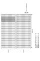
- FIG. 18A is a diagram illustrating an example of a semi-static HARQ codebook on the second PSFCH according to the third embodiment of the present disclosure; In FIG. 18A, one rectangle corresponds to a bit representing one HARQ-ACK information (ACK or NACK). Also, FIG. 18B is a diagram illustrating an example of transmission of the second PSFCH according to the third embodiment of the present disclosure.
- this semi-static HARQ codebook bits are allocated to slots, subchannels and carriers (cells) corresponding to PSFCHs to be transmitted. Therefore, in the same figure, the HARQ codebook is configured with 8 bits.
- the bits are associated in order of frequency (subchannel), time (slot), and cell.
- PSSCH is transmitted in slot #1 & subchannel #2, slot #2 & subchannel #1, slot #4 & subchannel #2, so correspondingly, second, third, and eighth HARQ-ACK is stored in the bit.
- NACK is stored in other bits.
- the order of bits stored in the semi-static HARQ codebook is associated with PSSCH candidate resources (PSSCH candidate slots and subchannels and carriers).
- semi-static resources can be excluded from the codebook if they are not available for PSSCH transmission.
- the cases where resources cannot be used for PSSCH transmission semi-statically include, for example, resources that are not set as resource pools, resources that are set as uplink resources, resources that are transmitted as S-SS/PSBCH, and other terminal devices. resources reserved by On the other hand, in the semi-static HARQ codebook, the corresponding bit is set to NACK even in the PSSCH where SL-HARQ-ACK feedback is unnecessary.
- a PSSCH that does not require SL-HARQ-ACK feedback is, for example, a PSSCH whose cast type is broadcast, a PSSCH indicated as disabled (unnecessary, invalid) by the HARQ feedback enabled/disabled indicator included in the second stage SCI, and so on.
- the HARQ codebook size can be reduced according to the number of bundling.
- the HARQ codebook size is aligned between the transmitting and receiving terminal devices. number and HARQ-ACK information are less likely to conflict.
- a Dynamic HARQ Codebook (Type 2 HARQ Codebook) may be applied.
- the dynamic HARQ codebook is configured to include only SL-HARQ-ACKs corresponding to PSSCHs actually sent. Unlike semi-static HARQ codebooks, SL-HARQ-ACKs corresponding to slots, subchannels and cells for which PSSCH was not sent (or not detected) do not feed back.
- FIG. 19A is a diagram illustrating an example of a dynamic HARQ codebook on the second PSFCH according to the third embodiment of the present disclosure; In FIG. 19A, one rectangle corresponds to a bit representing one HARQ-ACK information (ACK or NACK). Also, FIG. 19B is a diagram illustrating an example of transmission of the second PSFCH according to the third embodiment of the present disclosure.
- this dynamic HARQ codebook only HARQ-ACKs corresponding to the actual PSSCH are fed back. Therefore, in the example of FIG. 18A, only HARQ-ACKs corresponding to PSSCH #1, #2, and #3 generated are stored in the HARQ codebook and configured as a 3-bit HARQ codebook.
- the SCI includes an index (SAI: Sidelink Assignment Index) that counts the number of transmissions of the PSCCH/PSSCH in order to associate the bit order with the PSSCH.
- SAI Sidelink Assignment Index
- a counter SAI that counts the number of PSCCH/PSSCH sent in one cell and a total SAI that counts the number of PSCCH/PSSCH sent in all cells may be included.
- the SAI is preferably included in the second stage SCI which facilitates expansion of the number of bits.
- a PSSCH that does not require SL-HARQ-ACK feedback is, for example, a PSSCH whose cast type is broadcast, a PSSCH indicated as unnecessary or disabled by the HARQ feedback enabled/disabled indicator included in the second stage SCI, and so on.
- the HARQ codebook size can be reduced according to the number of bundling.
- a one-shot HARQ codebook (Type 3 HARQ Codebook) can be applied.
- the one-shot HARQ codebook is configured to include the HARQ-ACKs of all configured HARQ processes in the HARQ codebook.
- FIG. 20A is a diagram illustrating an example of a one-shot HARQ codebook on the second PSFCH according to the third embodiment of the present disclosure.
- FIG. 20B is a diagram illustrating an example of transmission of the second PSFCH according to the third embodiment of the present disclosure.
- the HARQ codebook when the number of HARQ processes is set to 16, the HARQ codebook consists of 16 bits, and HARQ-ACKs are stored in order of HARQ process IDs.
- the HARQ-ACKs corresponding to the HARQ processes of the PSSCHs that were not actually transmitted, although only three PSSCHs were actually transmitted, are also stored in the HARQ codebook.
- the HARQ-ACK value corresponding to the HARQ process of the PSSCH that has not been transmitted may be NACK or the default value (ACK or NACK).
- NACK the default value
- transmission decisions are made based on one-shot HARQ feedback triggers.
- the one-shot HARQ feedback trigger is preferably included in the second stage SCI.
- the one-shot HARQ feedback and other HARQ feedback overlap (collide)
- the one-shot HARQ feedback is transmitted and the other HARQ feedback is transmitted.
- HARQ feedback is preferably dropped.
- NACK is set to the corresponding bit even in PSSCH that does not require SL-HARQ-ACK feedback.
- a PSSCH that does not require SL-HARQ-ACK feedback is, for example, a PSSCH whose cast type is broadcast, a PSSCH indicated as disabled (unnecessary, invalid) by the HARQ feedback enabled/disabled indicator included in the second stage SCI, and so on.
- the HARQ codebook size can be reduced according to the number of bundling.
- the HARQ codebook may be configured to include HARQ-ACKs corresponding to all HARQ processes, even if HARQ bundling is configured.
- HARQ-ACK As an example of group-cast HARQ feedback operation in the second PSFCH, HARQ-ACK (ACK or NACK) is always fed back to the corresponding PSSCH even when NACK-only is indicated. That is, when NACK-only is indicated and the PSSCH decoding result is successful, ACK is set in the HARQ codebook and transmitted in the second PSFCH.
- the terminal device performs the same operation as for the first PSFCH.
- the second PSFCH is not transmitted, otherwise the second PSFCH is transmitted. If the second PSFCH was not sent, the transmitting terminal device recognizes that all NACK-only groupcast PSSCHs corresponding to the not sent second PSFCH were successfully decoded.
- the HARQ-ACK (ACK or NACK) corresponding to the PSSCH of the NACK-only group cast is stored in the HARQ codebook.
- a channel code of the second PSFCH is preferably applied to the second PSFCH, since the second PSFCH can carry more than one bit of information.
- a Reed-Muller code is applied when the number of bits is 11 bits or less, and a polar code is applied when the number of bits is more than 11 bits.
- An LDPC code is applied as another example of the channel code of the second PSFCH.
- Transmission power of the second PSFCH As an example of transmission power of one second PSFCH, it is calculated by the following formula.
- P PSFCH,k (i) P O,PSFCH +10log 10 (2 ⁇ ⁇ M RB PSFCH (i))+ ⁇ PSFCH ⁇ PL+ ⁇ TF,k (i)[dBm]
- k represents the index of the second PSFCH.
- i represents the index of the PSFCH transmission occasion.
- M RB PSFCH (i) represents the number of resource blocks for the second PSFCH in PSFCH transmission occasion i.
- K2 is 2.4.
- BPRE(i) (O ACK (i)+O CRC (i))/N RE (i).
- O ACK (i) is the number of SL-HARQ-ACK bits carried by the second PSFCH.
- Appropriate transmission power can be obtained from the above transmission power calculation formula when the second PSFCH is transmitted with 2 bits or more and/or 2 PRBs or more.
- the second PSFCH with low priority can be dropped until it becomes equal to or less than Pcmax.
- the priority may be specified by the SCI, may be set by the RRC setting, or may be tied to the resource.
- the priority of the second PSFCH is determined based on priority handling in the second PSFCH, which will be described later.
- SL-HARQ-ACK corresponding to PSSCH with a low priority can be excluded from the HARQ codebook of the second PSFCH until it becomes Pcmax or less.
- the priority is the value of the priority index specified by the SCI.
- transmission or reception of the second PSFCH containing SL-HARQ-ACK with the highest priority can be prioritized. If there are multiple second PSFCHs containing SL-HARQ-ACK with the highest priority, the second PSFCH containing SL-HARQ-ACK with the next highest priority is preferred.
- transmission or reception of the second PSFCH with the largest number of bits can be prioritized.
- the sum of the priorities of the SL-HARQ-ACKs included can be the priority of the second PSFCH.
- the priority of the second PSFCH can be determined based on the value indicated by the SCI.
- the control unit 203 of the terminal device 2 shown in FIG. 3 selects the first PSFCH and the second PSFCH and controls the transmission unit 207 to transmit.
- the first PSFCH is an example of the first sidelink feedback channel described in the claims.
- the second PSFCH is an example of the claimed second sidelink feedback channel.
- SL-HARQ-ACK is an example of response information described in the claims.
- the control section 203 selects the first PSFCH and the second PSFCH, and controls the transmission section 207 to transmit.
- An example of switching between the first PSFCH transmission and the second PFSCH transmission is listed below.
- the first PSFCH transmission is applied, and when it is 2 bits or more, the second PSFCH transmission is performed. applies.
- the first PSFCH transmission is applied, and when the set number of cells is 2 cells or more (i.e., carrier aggregation is set), the second PSFCH transmission is applied.
- the setting of the number of cells for carrier aggregation is preferably set semi-statically (by RRC signaling). At the same time, in this condition, switching between the first PSFCH transmission and the second PSFCH transmission is configured semi-statically.
- application of the first PSFCH or the second PSFCH can be selected according to the PSFCH format instruction included in the SCI.
- a first PSFCH transmission is applied if the PSFCH format indication specifies a first PSFCH
- a second PSFCH transmission is applied if the PSFCH format indication specifies a second PSFCH.
- the PSFCH format indication may be included in the PSFCH resource indication (PRI), and so on.
- the indication of the PSFCH resource is preferably included in a second stage SCI format (eg SCI format 2-A, SCI format 2-B, SCI format 2-C).
- application of the first PSFCH or the second PSFCH can be selected according to scheduling instructions related to carrier aggregation by SCI.
- An example of a scheduling instruction related to carrier aggregation is the number of received SCIs corresponding to the same PSFCH transmission occasion.
- the first PSFCH transmission is applied if one SCI scheduling a PSSCH corresponding to the same PSFCH transmission occasion is received, and the second PSFCH is applied if more than one is received.
- Another example of a scheduling instruction related to carrier aggregation is an instruction for sidelink cross-carrier scheduling or multi-cell scheduling.
- the first PSFCH transmission is applied if neither cross-carrier nor multi-cell scheduling is indicated, and the second PSFCH transmission is applied if cross-carrier or multi-cell scheduling is indicated.
- application of the first PSFCH or the second PSFCH can be selected based on a field that counts the number of SL-HARQ-ACKs included in the SCI.
- a field that counts the number of SL-HARQ-ACKs is, for example, SAI (Sidelink Assignment Index) and is used to determine the size of the HARQ codebook of the second PSFCH.
- SAI Segmentlink Assignment Index
- the first PSFCH transmission is applied when the SAI included in the SCI indicates 1, and the second PSFCH transmission is applied when the SAI indicates 2 or more.
- Application of the first PSFCH or the second PSFCH can be selected based on the features and/or capabilities implemented by the transmitting terminal device that transmits the PSSCH.
- application of the first PSFCH or the second PSFCH can be selected depending on whether the transmitting terminal device supports reception of the second PSFCH.
- the first PSFCH transmission is applied if the transmitting terminal device that transmits the PSSCH does not support the second PSFCH reception, and the second PSFCH transmission is applied if the second PSFCH reception is supported.
- a terminal device that does not support reception of the second PSFCH is a terminal device that supports the sidelink of 3GPP Release 17 or earlier, a terminal device that has notified that it does not support reception of the second PSFCH by capability information, etc.
- application of the first PSFCH or the second PSFCH can be selected according to the number of sidelink reception chains (reception baseband circuits and reception RF circuits) of the transmitting terminal device. If the side link reception chain of the transmitting terminal device is equal to or greater than the number of cells set by carrier aggregation, the first PSFCH transmission is applied, and if it is less than the set number of cells (for example, one case), the second PSFCH transmission is applied.
- sidelink reception chains reception baseband circuits and reception RF circuits
- application of the first PSFCH or the second PSFCH can be selected according to the carrier aggregation capability of the transmitting terminal device.
- capabilities related to carrier aggregation include a configurable number of received cells, support for cross-carrier scheduling, and the like. If it does not have the capability for carrier aggregation, it applies the first PSFCH transmission, and if it does have the capability for carrier aggregation, it applies the second PSFCH transmission.
- Application of the first PSFCH or the second PSFCH can be selected based on the features and/or capabilities implemented by the receiving terminal that receives the PSSCH.
- application of the first PSFCH or the second PSFCH can be selected depending on whether the receiving terminal device supports the second PSFCH transmission. If the receiving terminal receiving the PSSCH does not support the second PSFCH transmission, the first PSFCH transmission is applied, and if it supports the second PSFCH transmission, the second PSFCH transmission is applied. .
- a terminal device that does not support the second PSFCH transmission includes a terminal device that supports the sidelink of 3GPP Release 17 or earlier, a terminal device that has notified that the second PSFCH transmission is not supported by capability information, etc. is given.
- application of the first PFSCH or the second PSFCH can be selected based on the maximum number of simultaneous transmissions of the first PSFCH of the receiving terminal device.
- the first PSFCH transmission is applied when the number of SL-HARQ-ACK bits that need to be transmitted simultaneously is equal to or less than the maximum number of simultaneous transmissions of the first PSFCH, and is greater than the maximum number of simultaneous transmissions of the first PSFCH. is applied to the second PSFCH transmission.
- application of the first PSFCH or the second PSFCH can be selected according to the number of transmission chains (transmission baseband circuits and transmission RF circuits). If the side link transmission chain of the receiving terminal device is equal to or greater than the number of cells set by carrier aggregation, the first PSFCH transmission is applied, and if it is less than the set number of cells (for example, one case), the second PFSCH transmission is applied.
- application of the first PSFCH or the second PSFCH can be selected according to the capability related to carrier aggregation of the receiving terminal device.
- capabilities related to carrier aggregation include a configurable number of transmission cells, support for cross-carrier scheduling, and the like. If it does not have carrier scheduling capability, it applies the first PSFCH transmission, and if it does have carrier scheduling capability, it applies the second PSFCH transmission.
- a maximum transmission power Pcmax is defined for the terminal device, and it is difficult to allocate transmission power exceeding the maximum transmission power. Therefore, there is a possibility that the transmission of the PSFCH that cannot satisfy the transmission request will be dropped (discarded).
- Application of the first PSFCH or the second PSFCH can be selected depending on the PSFCH drop due to transmission power limitation.
- a first PSFCH transmission is applied when all the first PSFCHs can be transmitted due to transmission power limitations, and a second PSFCH is used when one or more of the first PSFCHs are dropped.
- N Tx,1st PSFCH is the planned number of transmissions of the first PSFCH.
- HARQ bundling A technique called HARQ bundling that bundles multiple HARQ-ACKs as one HARQ-ACK can be considered.
- HARQ bundling feed back a 1-bit ACK if all HARQ-ACKs are ACKs, and a 1-bit NACK otherwise.
- Another example of HARQ bundling is to feed back a 1-bit NACK if all HARQ-ACKs are NACKs, and a 1-bit ACK otherwise.
- application of the first PSFCH or tick PSFCH can be selected.
- a first PSFCH transmission is applied if HARQ bundling is applied among multiple serving cells, and a second PSFCH transmission is applied if HARQ bundling is not applied.
- (Condition 9) Cast type Based on the cast type, application of the first PSFCH or the second PSFCH can be selected.
- the first PSFCH transmission is applied to the corresponding HARQ-ACK feedback if the cast type indicates NACK-only group-cast, and the corresponding HARQ-ACK if unicast or ACK/NACK group-cast is indicated.
- a second PSFCH transmission is applied for feedback.
- RRC configuration Application of the first PSFCH or the second PSFCH can be selected based on the RRC configuration. If the second PSFCH was not configured by RRC configuration (or the first PSFCH was configured), the first PSFCH is applied, and the second PSFCH is configured (or the first PSFCH is not configured), then the second PSFCH is applied.
- RRC settings include whether or not to apply the second PSFCH (enabled/disabled), settings related to resources of the second PSFCH (slot cycle, resource block), settings related to transmission of the second PSFCH (transmission power settings , ), settings related to sidelink carrier aggregation, and the like.
- the RRC setting may be dedicated RRC signaling individually set for the terminal device, or may be system information (MIB or SIB) broadcast throughout the cell.
- MIB system information
- DCI indication Application of the first PSFCH or the second PSFCH can be selected based on the value of the field included in the DCI.
- the DCI is a DCI (eg DCI Format 3_0, DCI Format 3_1) that is used in resource allocation mode 1 and is used to instruct sidelink transmission.
- application of the first PSFCH or the second PSFCH can be selected according to the PSFCH format instruction included in the DCI.
- a first PSFCH transmission is applied if the PSFCH format indication specifies a first PSFCH
- a second PSFCH transmission is applied if the PSFCH format indication specifies a second PSFCH.
- application of the first PSFCH or the second PSFCH can be selected according to the value of the field that notifies other information included in the DCI.
- Other fields are, for example, Resource Pool Index, HARQ process number, Lowest index of the subchannel allocation, SCI format 1-A fields, PSFCH-to-HARQ feedback timing indicator, PU CCH resource indicator, Configuration index, Counter sidelink assignment index, carrier indicator, and the like. If these other fields indicate a predetermined value, the first PSFCH is applied, otherwise the second PSFCH is applied.
- An example of a combination is RRC setting and SCI indication.
- the second PSFCH is applied when the second PSFCH is configured by RRC configuration and the second PSFCH transmission is indicated by SCI, otherwise the first PSFCH is Applies.
- Another example of a combination is the capabilities of the sending terminal device and the capabilities of the receiving terminal device.
- the second PSFCH is applied, otherwise the first PSFCh is applied.
- Another example of a combination is transmission power control and half-duplex limit.
- transmission power control and half-duplex limit As a specific example, if one or more SL-HARQ-ACKs need to be dropped due to transmit power limitations and half-duplex limitations, then the second PSFCH is applied, otherwise the first PSFCH. applies.
- FIG. 21 is a diagram showing an example of a communication method according to the third embodiment of the present disclosure.
- FIG. 2 is a diagram showing an example of processing when the terminal device on the transmitting side determines switching of PSFCH transmission.
- the terminal device 2c on the transmitting side selects application of the first PSFCH or the second PSFCH based on the PSFCH switching conditions (step S101), and notifies the receiving terminal device of the selection result (step S102).
- the terminal device 2c on the transmitting side transmits a frame including the PSCCH and the PSSCH (step S103).
- the terminal device 2d on the receiving side transmits a PSFCH based on the selection result notified from the terminal device 2c on the transmitting side.
- the terminal device 2c on the transmitting side transmits a frame including the first PSFCH or the second PSFCH according to the selection result (step S104).
- the instruction of the PSFCH transmission method from the terminal device 2c on the transmitting side to the terminal device 2d on the receiving side may be notified before PSCCH and PSSCH transmission, may be notified at the same time, or may be notified before PSFCH transmission.
- the indication may be included in the SCI, may be included in the PSSCH, or other physical parameters (eg, DMRS sequence, PSFCH resource, sequence or cyclic shift value, PSSCH transmission slot and/or PRB , etc.).
- condition 1 the number of SL-HARQ-ACK bits that need to be transmitted at the same time
- condition 2 number of cells set by carrier aggregation
- condition 3 indication of SCI
- condition 4 capability of transmitting terminal device
- condition 5 capability of receiving terminal device
- condition 7 HARQ bundling
- condition 9 cast type
- the terminal device 2c on the transmitting side sends information necessary for making a decision to the terminal device 2d on the receiving side, other terminal devices 2, and/or the base station device. 1 may be obtained in advance.
- Information necessary for the determination includes, for example, sidelink settings (PSFCH resources), carrier aggregation settings, and information on the terminal device 2d on the receiving side (capability, transmission/reception timing, transmission power), and the like.
- FIG. 22 is a diagram showing another example of the communication method according to the third embodiment of the present disclosure.
- the figure shows an example in which the terminal device 2d on the receiving side selects application of the first PSFCH or the second PSFCH based on the PSFCH switching conditions.
- the terminal device 2d on the receiving side selects application of the first PSFCH or the second PSFCH based on the PSFCH switching conditions (step S111).
- the terminal device 2d on the receiving side notifies the terminal device 2c on the transmitting side of the selection result (PSFCH transmission method).
- step S114 the terminal device 2d on the receiving side transmits the first PSFCH or a frame including the PSFCH based on the selected PSFCH transmission method.
- the instruction of the PSFCH transmission method from the terminal device 2d on the receiving side to the terminal device 2c on the transmitting side may be notified before PSCCH and PSSCH reception, may be notified before PSFCH transmission, or may be notified before PSFCH transmission. may be notified at the same time.
- the indication may be included in the SCI, may be included in the PSSCH, or other physical parameters (eg, DMRS sequence, PSFCH resource, sequence, or cyclic shift value, PSSCH transmission slot and/or PRB, etc.).
- the instruction from the terminal device 2d on the receiving side is implicitly notified using physical parameters related to the PSFCH. be done.
- the terminal device 2c on the transmission side can recognize the PSFCH format by blindly detecting the PSFCH from each resource.
- condition 1 the number of SL-HARQ-ACK bits that need to be transmitted at the same time
- condition 2 number of cells set by carrier aggregation
- Condition 4 transmitting terminal device capability
- Condition 5 receiving terminal device capability
- Condition 6 transmission power limit
- Condition 7 HARQ bundling
- condition 8 Hyf Duplex constraint
- the terminal device 2d on the receiving side receives information necessary for making a decision from the terminal device 2c on the transmitting side, other terminal devices, and/or the base station. It may be obtained in advance.
- Information necessary for the determination includes, for example, sidelink settings (PSFCH resources), carrier aggregation settings, information on the transmitting terminal device (capability, transmission/reception timing), and the like.
- FIG. 23 is a diagram showing another example of the communication method according to the third embodiment of the present disclosure.
- the figure shows an example in which the base station apparatus 1 selects application of the first PSFCH or the second PSFCH based on the PSFCH switching conditions.
- the control unit 103 of the base station apparatus 1 shown in FIG. 2 selects the first PSFCH and the second PSFCH and controls the transmission unit 107 to transmit.
- the base station apparatus 1 selects application of the first PSFCH or the second PSFCH based on the PSFCH switching conditions (step S121), and notifies the terminal apparatuses 2c and 2d of the selection result together with sidelink communication settings. (Steps S122 and S123).
- the terminal device 2c on the transmitting side and the terminal device 2d on the receiving side perform sidelink communication based on the PSFCH transmission method instructed by the base station (steps S124 and S125).
- the base station may notify only the terminal device 2c on the transmitting side or only the terminal device 2d on the receiving side of the PSFCH transmission method. You may notify both of the terminal devices 2d. Also, the terminal device that has received the PSFCH transmission method may notify other terminal devices.
- the instruction of the PSFCH transmission method from the base station apparatus 1 to the terminal apparatus may be notified before PSCCH and PSSCH transmission/reception, or may be notified before PSFCH transmission/reception.
- the indication is included in system information (SIB), dedicated RRC signaling, MAC CE, DCI, and the like.
- condition 1 the number of SL-HARQ-ACK bits that need to be transmitted simultaneously
- condition 2 carrier aggregation number of cells configured by
- Condition 4 transmitting terminal device capability
- Condition 5 receiving terminal device capability
- Condition 7 HARQ bundling
- Condition 10 RRC configuration
- Condition 11 indication of DCI
- the base station apparatus 1 may acquire in advance information necessary for the determination from the terminal apparatus before determining whether to switch the PSFCH transmission.
- Information necessary for determination includes, for example, sidelink settings (PSFCH resources), terminal device locations or zones, carrier aggregation settings, information on terminal devices (capacity, transmission/reception timing, transmission power), and the like. .
- multiple SL-HARQ-ACKs for different transmitting terminal devices can be included in one sidelink physical channel (second PSFCH) and transmitted.
- the transmission resources of the second PSFCH containing multiple SL-HARQ-ACKs for different transmitting terminals can be configured, for example, based on destination IDs, higher layer parameters and/or receiving terminal selections. .
- the communication device selects the first PSFCH and the second PSFCH including multiple pieces of response information to perform sidelink communication. This makes it possible to improve the communication speed and the like in sidelink communication to which carrier aggregation is applied.
- the first PSFCH is transmitted.
- the LBT before the first PSFCH transmission fails, the first PSFCH cannot be transmitted, so the first PSFCH is dropped.
- COT Channel Occupancy Time
- the second PSFCH is always applied.
- the first PSFCH is not applied.
- sidelink operation in unlicensed bands means, for example, operation in shared spectrum, predetermined bands (bands including 2.4 GHz band/5 GHz band/6 GHz band, band n46, etc.) Operations, operations where DBTW (Discovery Burst Transmission Window) is valid, operations where LBT is required before transmission, or other functions required for unlicensed operation (interlaced waveforms, narrowband frequency hopping, etc.) are valid. In other words, it is an operation.
- DBTW Discovery Burst Transmission Window
- retransmission of dropped HARQ-ACK may be instructed, or one-shot HARQ may be instructed.
- the dropped HARQ-ACK retransmission indication is, for example, a PSSCH group indication.
- NACK-only groupcast is not used and is disabled.
- ACK-only group-cast is applied instead of NACK-only group-cast.
- ACK-only groupcast multiple terminal devices in groupcast transmit PSFCH on the same resource only in case of ACK.
- a NACK-only groupcast cannot be transmitted due to an LBT failure, a NACK is transmitted at a later timing.
- the transmitting terminal device does not recognize ACK until a predetermined period has passed since the NACK-only loopcast was transmitted. That is, when the transmitting terminal apparatus receives the PSFCH within a predetermined period, it recognizes that the group cast is NACK, and when it does not receive the PSFCH from any receiving terminal apparatus even after the predetermined period passes, the group cast is recognized as ACK.
- the first PSFCH may be applied, or the second PSFCH may be applied.
- a control device that controls the management device 10, the base station 20, the relay station 30, and the terminal device 40 of this embodiment may be realized by a dedicated computer system or by a general-purpose computer system.
- a communication program for executing the above operations is distributed by storing it in a computer-readable recording medium such as an optical disk, semiconductor memory, magnetic tape, or flexible disk.
- the control device is configured by installing the program in a computer and executing the above-described processing.
- the control device may be a device (for example, a personal computer) external to the management device 10, the base station 20, the relay station 30, and the terminal device 40.
- the control device may be a device inside the management device 10, the base station 20, the relay station 30, and the terminal device 40 (for example, the control unit 13, the control unit 23, the control unit 33, and the control unit 43).
- the above communication program may be stored in a disk device provided in a server device on a network such as the Internet, so that it can be downloaded to a computer.
- the functions described above may be realized through cooperation between an OS (Operating System) and application software.
- the parts other than the OS may be stored in a medium and distributed, or the parts other than the OS may be stored in a server device so that they can be downloaded to a computer.
- each component of each device illustrated is functionally conceptual and does not necessarily need to be physically configured as illustrated.
- the specific form of distribution and integration of each device is not limited to the illustrated one, and all or part of them can be functionally or physically distributed and integrated in arbitrary units according to various loads and usage conditions. Can be integrated and configured. Note that this distribution/integration configuration may be performed dynamically.
- the present embodiment can be applied to any configuration that constitutes a device or system, such as a processor as a system LSI (Large Scale Integration), a module using a plurality of processors, a unit using a plurality of modules, etc. Furthermore, it can also be implemented as a set or the like (that is, a configuration of a part of the device) to which other functions are added.
- a processor as a system LSI (Large Scale Integration)
- module using a plurality of processors a unit using a plurality of modules, etc.
- it can also be implemented as a set or the like (that is, a configuration of a part of the device) to which other functions are added.
- the system means a set of a plurality of components (devices, modules (parts), etc.), and it does not matter whether all the components are in the same housing. Therefore, a plurality of devices housed in separate housings and connected via a network, and a single device housing a plurality of modules in one housing, are both systems. .
- this embodiment can take a configuration of cloud computing in which one function is shared by a plurality of devices via a network and processed jointly.
- the present technology can also take the following configuration.
- a receiver that receives a sidelink shared channel for sidelink communication, which is inter-device communication;
- a transmission unit that transmits a first sidelink feedback channel and a second sidelink feedback channel for transmitting response information on the sidelink shared channel;
- a communication device comprising: a control unit that selects the first sidelink feedback channel and the second sidelink feedback channel and controls the transmitting unit to transmit the selected sidelink feedback channel.
- the first sidelink feedback channel includes one or less of the response information
- the control unit selects the second sidelink feedback channel when transmitting a plurality of the response information.
- the communication device selects the second sidelink feedback channel when performing the sidelink communication using a plurality of cells.
- the communication device performs the selection based on sidelink control information that is information on the sidelink shared channel.
- the control section performs the selection based on the number of simultaneous transmissions of the first sidelink feedback channels in the transmission section.
- the communication device performs the selection based on transmission power of the transmission section.
- the control unit selects the second sidelink feedback channel when another communication device can receive the transmitted response information when the response information is transmitted. communication equipment.
- the communication device (9) The communication device according to (1) or (2), wherein the control unit performs the selection based on a cast type of the sidelink communication.
- a first sidelink feedback channel and a second sidelink feedback channel for transmitting response information of the sidelink shared channel for the sidelink communication to the communication device that performs sidelink communication, which is inter-device communication.
- a communication device having a control unit that controls selection and transmission of information on the selection result.
- a communication method comprising selecting the first sidelink feedback channel and the second sidelink feedback channel and controlling a transmitting unit to transmit the selected sidelink feedback channel.
- a first sidelink feedback channel and a second sidelink feedback channel for transmitting response information of the sidelink shared channel for the sidelink communication to the communication device that performs sidelink communication, which is inter-device communication.
- a communication method comprising making a selection and controlling transmission of information on the selection result.
Landscapes
- Engineering & Computer Science (AREA)
- Signal Processing (AREA)
- Computer Networks & Wireless Communication (AREA)
- Mobile Radio Communication Systems (AREA)
Abstract
Description
[無線通信システム]
本実施形態において、無線通信システムは、基地局装置1および端末装置2を少なくとも具備する。基地局装置1は複数の端末装置を収容できる。基地局装置1は、他の基地局装置とX2インターフェースの手段によって互いに接続できる。また、基地局装置1は、S1インターフェースの手段によってEPC(Evolved Packet Core)に接続できる。さらに、基地局装置1は、S1-MMEインターフェースの手段によってMME(Mobility Management Entity)に接続でき、S1-Uインターフェースの手段によってS-GW(Serving Gateway)に接続できる。S1インターフェースは、MMEおよび/またはS-GWと基地局装置1との間で、多対多の接続をサポートしている。また、本実施形態において、基地局装置1および端末装置2は、それぞれLTEおよび/またはNRをサポートする。
図1は、本開示の実施形態に係るサイドリンク通信の概要を示す図である。1つのユースケースとして、基地局装置1が構成するセル3の内部に2つ以上の端末装置2が存在し、サイドリンク通信を行う場合を挙げることができる。他のユースケースとして、基地局装置1が構成するセル3の内部に2つ以上の端末装置2のうちの少なくとも1つの端末装置2が存在し、他方の端末装置2がそのセル3の外部に存在する場合において、サイドリンク通信を行う場合を挙げることができる。更に、セル3の内部に存在する端末装置2は、基地局装置1と通信を行うことにより、基地局装置1とセル3の外部に存在する端末装置2との中継を行うことができる。
図2は、本開示の実施形態に係る基地局装置1の構成を示す概略ブロック図である。図示するように、基地局装置1は、上位層処理部101、制御部103、受信部105、送信部107、および、送受信アンテナ109、を含んで構成される。また、受信部105は、復号化部1051、復調部1053、多重分離部1055、無線受信部1057、およびチャネル測定部1059を含んで構成される。また、送信部107は、符号化部1071、変調部1073、多重部1075、無線送信部1077、および下りリンク参照信号生成部1079を含んで構成される。
図3は、本開示の実施形態に係る端末装置2の構成を示す概略ブロック図である。図示するように、端末装置2は、上位層処理部201、制御部203、受信部205、送信部207、および送受信アンテナ209を含んで構成される。また、受信部205は、復号化部2051、復調部2053、多重分離部2055、無線受信部2057、およびチャネル測定部2059を含んで構成される。また、送信部207は、符号化部2071、変調部2073、多重部2075、無線送信部2077、および上りリンク参照信号生成部2079を含んで構成される。
サイドリンク通信とは、端末装置とその端末装置とは異なる端末装置との直接通信である。サイドリンクには、リソースプールと呼称されるサイドリンクの送受信に用いられる時間および周波数リソースの候補が端末装置に設定される。そのリソースプールの中からサイドリンクの送受信のためのリソースが選択され、サイドリンク通信が行われる。サイドリンク通信は、上りリンクのリソース(上りリンクサブフレーム、上りリンクコンポーネントキャリア)を用いて行われるため、リソースプールも上りリンクサブフレームまたは上りリンクコンポーネントキャリアに設定される。
図4及び5は、本開示の実施形態に係るサイドリンクのフレームの構成例を示す図である。図4は、PSCCHが2シンボル構成のサイドリンクのフレームの例を表したものである。また、図4のフレームは、DMRSが2シンボル割り当てられ、PSFCHが割り当てられない場合の例を表したものである。
リソースプールは、SIBまたは専用RRCメッセージによって基地局装置から端末装置に設定される。もしくは、端末装置に予め設定されたリソースプールに関する情報によって設定される。時間のリソースプールは、周期の情報、オフセットの情報、および、サブフレームビットマップ情報によって指示される。周波数のリソースプールは、リソースブロックの開始位置、リソースブロックの終了位置、および連続するリソースブロック数によって指示される。
サイドリンクへのリソース割り当ての方式としては、基地局装置がサイドリンク物理チャネル(PSCCH及びPSSCH)の送信のためのリソースを割り当てる「リソース割当モード1(Sidelink Resource allocation mode 1)」の方式と、端末装置自身でセンシングを行い、サイドリンク物理チャネルの送信のためのリソースを選択する「リソース割当モード2(Sidelink Resource allocation mode 2)」の方式とがある。
リソース割当モード1では、端末装置に送信パケットが発生すると、リソースプールのうち当該パケットの送信に使用すべきリソースが基地局装置により割り当てられる。
リソース割当モード2では、リソースプールが予め基地局装置やネットワークによって割り当てられる。
リソース割当モード2(a):端末装置が送信サイドリンクリソースを自律的に選択
リソース割当モード2(b):端末装置が他の送信端末のサイドリンクリソース選択を補助
リソース割当モード2(c):コンフィグアードグラントによるサイドリンク送信
リソース割当モード2(d):端末装置は他の端末装置のサイドリンク送信をスケジュール
リソース割当モード2(a)では、端末装置でパケットが発生すると、端末装置はリソースプールのうち当該パケットの送信に使用するサイドリンクリソースを自律的に選択する。パケットを送信する端末装置は、まず、当該パケットの送信に利用するサイドリンクリソースをリソースプール内から発見するためにセンシングを行う。次いで、端末装置は、当該センシングの結果に基づき、当該リソースプール内からのサイドリンクリソースの選択を行う。そして、端末装置は、選択したサイドリンクリソースを利用してパケットの送信を行う。また、このとき端末装置は、必要に応じて、以降におけるパケットの送信に利用するサイドリンクリソースの予約を行う。
リソース割当モード2(c)では、端末装置にサイドリンク送信パターンが設定される。端末装置は、設定されたサイドリンク送信パターンに従って、送信に用いられるサイドリンクリソースを選択する。
図7に、本開示の実施形態に係るリソース割当モード2(d)の一例を示す図である。リソース割当モード2(d)は、3つ以上の端末装置で構成されるグループベースサイドリンク通信において適用される。グループ内では、代表の端末装置(1次端末装置)が定義される。代表の端末装置は、グループ内の他の端末装置(2次端末装置またはメンバー端末装置)の情報を基地局装置に報告する。基地局装置1は、グループ内の各端末装置のリソースプール設定やリソース設定を代表の端末装置を経由して提供する。リソース割当モード2(d)では、メンバー端末装置は、基地局装置との直接接続を必要としないため、Uuリンク(基地局装置と端末装置間の通信リンク)のシグナルオーバーヘッドを低減することができる。代表の端末装置となり得る端末装置および提供可能な機能は、端末装置のケイパビリティに依存して決まる。
リソース割当モード2において、センシングプロシージャがサポートされる。サイドリンクにおけるセンシングとして、他の端末装置からのSCI復号、および/または、サイドリンクリソースの測定が用いられる。
サイドリンクにおいて、キャストタイプがユニキャストまたはグループキャスト、かつ、HARQ-enabledと指示された場合に、送信されたPSSCHに対する応答情報(HARQ-ACK、ACK/NACK情報)がPSSCHを送信した端末装置に対して送られる。PSSCHに対するHARQ-ACK(SL-HARQ-ACK)の送信は、PSFCHが用いられる。
図8は、本開示の実施形態に係るPSSCHとPSFCHリソースの関係の一例を示す図である。同図は、PSFCHのスロット周期が2スロット及び時間ギャップが2スロットの場合におけるPSSCHとPSFCHリソースの関係を表す図である。
1つのPSFCHの送信電力は以下の式によって計算される。
PPSFCH,one=PO,PSFCH+10log10(2μ)+αPSFCH×PL[dBm]
ここで、PO,PSFCHは上位層パラメータdl-P0-PSFCHの値を表す。また、αPSFCHは上位層パラメータdl-Alpha-PSFCHの値を表し、dl-Alpha-PSFCHが与えられなかった場合には値「1」になる。PLは下りリンクパスロスを表す。μはSCS設定を表す。
同じPSFCH送信オケイジョン(occasion)で送信を予定している1つ以上のPSFCHと受信を予定している1つ以上のPSFCHが同時に発生した場合、端末装置は、PSFCHの中から最もプライオリティが高いPSFCHに基づいて、送信または受信動作を決定する。具体的には、端末装置は、最もプライオリティが高いPSFCHが送信を予定しているPSFCHであった場合、PSFCH送信オケイジョンにおいて送信を行い、最もプライオリティが高いPSFCHが受信を予定しているPSFCHであった場合、PSFCH送信オケイジョンにおいて受信を行う。
公衆安全(Public Safety)のための通信や車間通信(V2X:Vehicle to Anything)を主なユースケースとして、3GPPにてサイドリンクは導入された。更に、V2Xのみならず、XRゲーミング、XRコンテンツのリアルタイム共有、メディア共有、無線テザリング、産業IoTネットワーク、ホームネットワークなど、商用利用(commercial use)の通信にサイドリンクの活用が期待されている。
図9は、本開示の実施形態に係るサイドリンクのキャリアアグリゲーションの一例を示す図である。同図では、PSSCH送信のためのセル(キャリア)が2つ設定される。各セルの送受信に対応するように2つの送受信機を備えることにより、それぞれのセルからPSSCHを同時に送信することが可能となる。例えば、同図において、1番目と6番目のスロットにおいて、2つのPSSCHが同時に送信される。キャリアアグリゲーションによって、スループットを向上することができる。
キャリアアグリゲーションにより複数のセルが設定され、かつ、ユニキャストまたはグループキャストのPSSCHが同時に送信された場合、フィードバックが必要なSL-HARQ-ACKが同時に複数発生する。キャリアアグリゲーションにおける複数のSL-HARQ-ACKのフィードバック手法は議論されていない。
本発明における実施形態では、サイドリンクのキャリアアグリゲーションにおいて、複数のサイドリンクHARQ-ACK(SL-HARQ-ACK)を運ぶことが可能なPSFCHの構成およびサイドリンクHARQ-ACK(SL-HARQ-ACK)フィードバックの制御手法を提供する。
本開示の第1の実施形態では、各セルで発生するSL-HARQ-ACKが各セルのPSFCHで送信される例について説明する。この第1の実施形態は、言い換えると、SL-HARQ-ACKは、対応するPSSCHが送信されたセルとは異なるセルでは送られない実施形態である。
図10は、本開示の第1の実施形態に係るPSFCHの複数同時送信の一例を示す図である。同図は、2つのセルが設定され、1番目と4番目のスロットにPSSCH送信が同時に発生する一例を示す。この場合、1番目のPSSCHに対応する2つのSL-HARQ-ACKは3番目のスロットの同じセルでPSFCHが同時に送られる。また、4番目のPSSCHに対応する2つのSL-HARQ-ACKは7番目のスロットの同じセルでPSFCHが同時に送られる。
本開示の第2の実施形態では、複数の第1のPSFCHを同時送信可能な端末装置であれば、第1の実施形態を適用することは容易である。一方で、実装された送信ベースバンド/送信RF数の制限、総送信電力の制限、半二重の制限、など第1の実施形態を適用することが困難な状況が考えられ得る。そのような状況では、第2の実施形態の適用が有効である。
図11は、本開示の第2の実施形態に係る第2のPSFCHの送信の一例を示す図である。同図は、図10と同様に、2つのセルが設定され、1番目と4番目のスロットにPSSCH送信が同時に発生する例を示す。第1の実施形態とは異なり、1番目のスロットで送信されたセル2のPSSCHに対応するSL-HARQ-ACKはセル1のPSFCHで送信される。また、4番目のスロットで送信されたセル1のPSSCHに対応するSL-HARQ-ACKはセル2のPSFCHで送信される。
第3の実施形態では、第1の実施形態であるPSFCHの同時送信と第2の実施形態である第2のPSFCH送信を組み合わせて適用される実施形態である。
図12は、本開示の第3の実施形態に係る第1のPSFCH及び第2のPSFCHの送信の一例を示す図である。同図では、3つのセルが設定され、それぞれのセルで同時にPSSCH送信が発生する。3番目のスロットのPSFCH送信オケイジョンにおいて、セル1のPSSCHに対応するSL-HARQ-ACKはセル1のPSFCHで送信され、セル2およびセル3のPSSCHに対応する2つのSL-HARQ-ACKはセル3のPSFCHで送信される。また、7番目のスロットのPSFCH送信オケイジョンにおいて、セル1およびセル3のPSSCHに対応する2つのSL-HARQ-ACKはセル1のPSFCHで送信され、セル2のPSSCHに対応するSL-HARQ-ACKはセル2のPSFCHで送信される。
第1のPSFCHと第2のPSFCHの送信衝突を防ぐため、第2のPSFCHのリソース領域は、第1のPSFCHのリソース領域とは異なるリソース領域で設定されることが好ましい。以下では、第2のPSFCHのリソース領域の一例を列挙する。
第2のPSFCHの物理チャネル構成の一例は、第1のPSFCHとは異なるPSFCHフォーマットである。例えば、第2のPSFCHは、PSFCHフォーマット1として呼称される。この第2のPSFCHフォーマットは、少なくとも、2つ以上のSL-HARQ-ACKを運ぶことが可能な特徴を有する。すなわち、第2のPSFCHは、複数のサブチャネル、キャリア、および/または、スロットで送信されたPSSCHに対応する複数のSL-HARQ-ACKを1つの物理チャネルで運ぶことができる。なお、第2のPSFCHフォーマットによって1つのSL-HARQ-ACKのみ運ぶこともできる。第2のPSFCHフォーマットは、例えば、2シンボルで構成することができる。
第2のPSFCHの物理チャネル構成の別の一例は、PSSCHとして定義される。すなわち、本一例では、PSSCHはSL-HARQ-ACKを運ぶことができる。
第2のPSFCHの送信リソースは、送信端末装置、受信端末装置、他の端末装置、または、基地局が決定する。以下では、第2のPSFCHの送信リソースの決定方法の一例を列挙する。
複数のHARQ-ACKを運ぶ際には、HARQ-ACKと物理共用チャネル(Physical Shared Channel)との紐づけ、および、サイズが定義される。複数のHARQ-ACKをまとめた構成をHARQコードブック(またはHARQ-ACKコードブック)と呼称される。サイドリンクにおいても、複数のSL-HARQ-ACKを1つの物理チャネル(第2のPSSCH)にまとめて運ぶ際には、HARQコードブックが適用される。
図18Aは、本開示の第3の実施形態に係る第2のPSFCHにおける準静的HARQコードブックの一例を示す図である。図18Aでは、1つの矩形が1つのHARQ-ACKの情報(ACKまたはNACK)を表すビットに対応する。また、図18Bは、本開示の第3の実施形態に係る第2のPSFCHの送信の一例を示す図である。この準静的HARQコードブックでは、送信予定のPSFCHと対応するスロット、サブチャネル、キャリア(セル)に対してビットが割り当てられる。このため、同図では、HARQコードブックが8ビットに構成される。このビットは周波数(サブチャネル)、時間(スロット)、セルの順番に対応付けられる。同図の例では、スロット#1&サブチャネル#2、スロット#2&サブチャネル#1、スロット#4&サブチャネル#2にPSSCHが送信されているため、対応して2番目、3番目、8番目のビットにHARQ-ACKが格納される。一方で、それ以外のリソースではPSSCHが送信されていないため、他のビットにはNACKが格納される。このように、準静的HARQコードブックでは格納されるビットの順番とPSSCH候補リソース(PSSCH候補スロットおよびサブチャネルおよびキャリア)が対応付けられる。
図19Aは、本開示の第3の実施形態に係る第2のPSFCHにおける動的HARQコードブックの一例を示す図である。図19Aでは、1つの矩形が1つのHARQ-ACKの情報(ACKまたはNACK)を表すビットに対応する。また、図19Bは、本開示の第3の実施形態に係る第2のPSFCHの送信の一例を示す図である。この動的HARQコードブックでは、実際のPSSCHに対応するHARQ-ACKのみフィードバックする。このため、図18Aの例では、発生するPSSCH#1、#2、#3に対応するHARQ-ACKのみHARQコードブックに格納され、3ビットのHARQコードブックとして構成される。
図20Aは、本開示の第3の実施形態に係る第2のPSFCHにおけるワンショットHARQコードブックの一例を示す図である。図20Bは、本開示の第3の実施形態に係る第2のPSFCHの送信の一例を示す図である。図20Aにおいて、HARQプロセス数が16と設定された場合、HARQコードブックは16ビットで構成され、HARQプロセスIDの順番にHARQ-ACKが格納される。図20Bの例では、実際には3つのPSSCHのみ送信されているが、送信されていないPSSCHのHARQプロセスに対応するHARQ-ACKも、HARQコードブックに格納される。送信されていないPSSCHのHARQプロセスに対応するHARQ-ACKの値は、NACKでもよいし、デフォルト値(ACKまたはNACK)でもよい。なお、図20Bにおいて、「PSFCH送信オケイジョンリソース」及び「PSSCH候補スロット及びサブチャネル」の記載を省略している。
第1のPSFCHにおいて、キャストタイプがNACKオンリーグループキャストと指示された場合、対応するPSSCHの復号結果が成功(ACK)であった場合にはPSFCHは送信されず、失敗(NACK)であった場合にはPSFCHが送信される。一方で、第2のPSFCHは、2つ以上のHARQ-ACKを含み得るため、第2のPSFCHにおけるグループキャストのHARQフィードバック動作の一例を以下に列挙する。
第2のPSFCHは2ビット以上の情報を運ぶことができるため、第2のPSFCHに対してチャネル符号が適用されることが好ましい。第2のPSFCHのチャネル符号の一例として、ビット数が11ビット以下の場合はリードマラー符号が適用され、ビット数が11ビットよりも多い場合はポーラ符号が適用される。第2のPSFCHのチャネル符号の別の一例として、LDPC符号が適用される。
1つの第2のPSFCHの送信電力の一例として、以下の式で計算される。
PPSFCH,k(i)=PO,PSFCH+10log10(2μ×MRB PSFCH(i))+αPSFCH×PL+ΔTF,k(i)[dBm]
ここで、kは第2のPSFCHのインデックスを表す。iはPSFCH送信オケイジョンのインデックスを表す。MRB PSFCH(i)はPSFCH送信オケイジョンiにおける第2のPSFCHのリソースブロック数を表す。また、ΔTF,kは第2のPSFCHの送信電力調整項であり、第2のPSFCHのビット数が11ビット以下の場合、
ΔTF,k(i)=10log10(K1×nSL-HARQ-ACK(i))/NRE(i)
である。ここで、K1は6である。また、nSL-HARQ-ACK(i)は第2のPSFCHによって運ばれるSL-HARQ-ACKのビット数を表す。NRE(i)は第2のPSFCHを復調するためのDMRSを抜いたリソースエレメント数を表す。また、第2のPSFCHのビット数が11ビットよりも多い場合、
ΔTF,k(i)=10log10(2K2×BPRE(i)-1)
である。ここで、K2は2.4となる。また、BPRE(i)=(OACK(i)+OCRC(i))/NRE(i)である。また、OACK(i)は第2のPSFCHによって運ばれるSL-HARQ-ACKのビット数である。
同じPSFCH送信オケイジョンにおいて、第1のPSFCHと第2のPSFCHが複数発生し、PSFCHで要求される総送信電力が端末装置の最大送信電力Pcmaxを超えた場合、PSFCHの送信電力を調整する必要がある。
同じPSFCH送信オケイジョンにおいて、第2のPSFCHの送信および受信が同時に発生した場合や、総送信電力が端末装置の最大送信電力Pcmaxを超えた場合など、第2のPSFCHの送信処理または受信処理を諦める必要がある。以下では、優先処理(プライオリティハンドリング)の一例を列挙する。
第2のPSFCHが適用可能な場合、第1のPSFCH送信と第2のPSFCH送信が、状況に応じて適宜切り替えられる。具体的には、制御部203が第1のPSFCH及び第2のPSFCHの選択を行い、送信部207に送信させる制御を行う。以下では、第1のPSFCH送信と第2のPFSCH送信の切り替えの一例を列挙する。
同時に送信が必要なSL-HARQ-ACKのビット数に応じて、第1のPFSCHまたは第2のPFSCHを選択することができる。
キャリアアグリゲーションによって設定されるセル数に基づいて、第1のPSFCHまたは第2のPSFCHの適用を選択することができる。
SCIに含まれるフィールドの値に基づいて、第1のPSFCHまたは第2のPSFCHの適用を選択することができる。
PSSCHを送信する送信端末装置が実装している機能(feature)および/または能力(capability)に基づいて、第1のPSFCHまたは第2のPSFCHの適用を選択することができる。
PSSCHを受信する受信端末装置が実装している機能(feature)および/または能力(capability)に基づいて、第1のPSFCHまたは第2のPSFCHの適用を選択することができる。
端末装置には最大送信電力Pcmaxが定義されており、最大送信電力を越えて送信電力を割り当てることが困難である。そのため、送信要求を満たせないPSFCHは送信がドロップ(破棄)される可能性がある。送信電力制限によるPSFCHドロップに応じて、第1のPSFCHまたは第2のPSFCHの適用を選択することができる。送信電力制限により全ての第1のPSFCHが送信可能である場合に第1のPSFCH送信が適用され、第1のPSFCHが1つ以上ドロップされる場合は第2のPSFCHが用いられる。
PPSFCH,one+10log10(NTx,1st PSFCH)≧P2nd PSFCH(i)
ここで、NTx,1st PSFCHは第1のPSFCHの送信予定数である。
複数のHARQ-ACKを1つのHARQ-ACKとして束ねるHARQバンドリングと称される技術が検討され得る。HARQバンドリングの一例として、全てのHARQ-ACKがACKの場合に1ビットのACK、そうでなければ1ビットのNACKをフィードバックする。HARQバンドリングの別の一例として、全てのHARQ-ACKがNACKの場合に1ビットのNACK、そうでなければ1ビットのACKをフィードバックする。このように、サービングセル間のHARQバンドリングの適用に応じて、第1のPSFCHまたはダニのPSFCHの適用を選択することができる。複数のサービングセル間でHARQバンドリングが適用された場合には第1のPSFCH送信が適用され、HARQバンドリングが適用されない場合には第2のPSFCH送信が適用される。
サイドリンクの同一帯域において、送信と受信を同時に行うことが困難であり、所定のタイミングにおいて送信または受信が選択される。送信または受信は、データの優先度、などに基づいて決定される。そのため、PSFCH送信オケイジョンで受信を行う場合、PSFCH送信はドロップ(破棄)される可能性がある。半二重制限によるPSFCHドロップに応じて、第1のPSFCHまたは第2のPSFCHの適用を選択することができる。SL-HARQ-ACKの送信タイミングで全てのセルで送信可能な場合は第1のPSFCHが適用され、送信不可能なセルが1つ以上存在する場合には第2のPSFCHが適用される。
キャストタイプに基づいて、第1のPSFCHまたは第2のPSFCHの適用を選択することができる。キャストタイプでNACKオンリーのグループキャストが指示された場合は対応するHARQ-ACKフィードバックに第1のPSFCH送信が適用され、ユニキャストまたはACK/NACKのグループキャストが指示された場合は対応するHARQ-ACKフィードバックに第2のPSFCH送信が適用される。
RRC設定に基づいて、第1のPSFCHまたは第2のPSFCHの適用を選択することができる。RRC設定によって第2のPSFCHが設定されなかった(または、第1のPSFCHが設定された)場合は第1のPSFCHが適用され、第2のPSFCHが設定された(または、第1のPSFCHが設定されなかった)場合は第2のPSFCHが適用される。RRC設定の一例として、例えば、第2のPSFCHの適用の有無(enabled/disabled)、第2のPSFCHのリソースに関する設定(スロット周期、リソースブロック)、第2のPSFCH送信に関する設定(送信電力の設定、)、サイドリンクキャリアアグリゲーションに関する設定、などが挙げられる。
DCIに含まれるフィールドの値に基づいて、第1のPSFCHまたは第2のPSFCHの適用を選択することができる。該DCIは、リソース割当モード1において用いられる、サイドリンク送信の指示に用いられるDCI(e.g. DCI Format 3_0, DCI Format 3_1)である。
以下では、PSFCH送信の切り替えのフロー図を説明する。PSFCH送信の切り替えを判断する主体の一例として、送信側の端末装置2c、受信側の端末装置2d、または、基地局装置1(またはプライマリ端末装置)の3主体が挙げられる。
本実施形態において、異なる送信端末装置に対する複数のSL-HARQ-ACKを1つのサイドリンク物理チャネル(第2のPSFCH)に含めて送信することができる。異なる送信端末装置に対する複数のSL-HARQ-ACKを含む第2のPSFCHの送信リソースは、例えば、デスティネーションID、上位層パラメータ、および/または、受信端末装置の選択に基づいて構成することができる。
異なるオペレーターおよび/またはノードが利用可能なアンライセンスバンドにおいて、信号を送信する前にLBT(Listen Before Talk、キャリアセンス、CCA)を行う必要がある。LBT成功した場合には、所定の期間中は送信可能であるが、LBT失敗した場合には、送信してはいけない。そのため、アンライセンスバンドのサイドリンク通信においても、LBT失敗した場合には、PSFCHを送信することができない。このような状況においても、第2のPSFCH適用が有効である。具体的には、第2のPSFCHを用いて、送信できなかったSL-HARQ-ACKを含めて送信することで、LBT失敗によって生じたHARQ-ACK送信失敗をリカバーすることができる。
キャストタイプがNACKオンリーグループキャストと指示された場合、端末装置はNACKのときだけPSFCHを送信する。一方で、アンライセンスバンドにおいて、LBT失敗した場合にはPSFCHが送信されない。この場合、送信端末装置は、ACKであるかLBT失敗であるかを区別することが困難である。アンライセンスバンドにおけるACKとLBT失敗の曖昧さ(Ambiguity)を回避する解決方法を以下に列挙する。
本実施形態の管理装置10、基地局20、中継局30、端末装置40、を制御する制御装置は、専用のコンピュータシステムにより実現してもよいし、汎用のコンピュータシステムによって実現してもよい。
(1)
装置間通信であるサイドリンク通信のためのサイドリンク共用チャネルを受信する受信部と、
前記サイドリンク共用チャネルの応答情報を送信するための第1のサイドリンクフィードバックチャネル及び第2のサイドリンクフィードバックチャネルを送信する送信部と、
前記第1のサイドリンクフィードバックチャネル及び前記第2のサイドリンクフィードバックチャネルの選択を行って前記送信部に送信させる制御を行う制御部と
を有する通信装置。
(2)
前記第1のサイドリンクフィードバックチャネルは、1以下の前記応答情報を含み、
前記第2のサイドリンクフィードバックチャネルは、複数の前記応答情報を含む
前記(1)に記載の通信装置。
(3)
前記制御部は、複数の前記応答情報を送信する際に前記第2のサイドリンクフィードバックチャネルを選択する
前記(1)又は(2)に記載の通信装置。
(4)
前記制御部は、複数のセルにより前記サイドリンク通信を行う際に前記第2のサイドリンクフィードバックチャネルを選択する
前記(1)又は(2)に記載の通信装置。
(5)
前記制御部は、前記サイドリンク共用チャネルの情報であるサイドリンク制御情報に基づいて前記選択を行う
前記(1)又は(2)に記載の通信装置。
(6)
前記制御部は、前記送信部における前記第1のサイドリンクフィードバックチャネルの同時送信可能数に基づいて前記選択を行う
前記(1)又は(2)に記載の通信装置。
(7)
前記制御部は、前記送信部における送信電力に基づいて前記選択を行う
前記(1)又は(2)に記載の通信装置。
(8)
前記制御部は、前記応答情報の送信時において当該送信される前記応答情報を他の通信装置が受信できる場合に前記第2のサイドリンクフィードバックチャネルを選択する
前記(1)又は(2)に記載の通信装置。
(9)
前記制御部は、前記サイドリンク通信のキャストタイプに基づいて前記選択を行う
前記(1)又は(2)に記載の通信装置。
(10)
装置間通信であるサイドリンク通信を行う通信装置に対し、前記サイドリンク通信のためのサイドリンク共用チャネルの応答情報を送信するための第1のサイドリンクフィードバックチャネル及び第2のサイドリンクフィードバックチャネルの選択を行って当該選択結果の情報を送信する制御を行う制御部
を有する通信装置。
(11)
装置間通信であるサイドリンク通信のためのサイドリンク共用チャネルを受信することと、
前記サイドリンク共用チャネルの応答情報を送信するための第1のサイドリンクフィードバックチャネル及び第2のサイドリンクフィードバックチャネルを送信することと、
前記第1のサイドリンクフィードバックチャネル及び前記第2のサイドリンクフィードバックチャネルの選択を行って送信部に送信させる制御を行うことと
を含む通信方法。
(12)
装置間通信であるサイドリンク通信を行う通信装置に対し、前記サイドリンク通信のためのサイドリンク共用チャネルの応答情報を送信するための第1のサイドリンクフィードバックチャネル及び第2のサイドリンクフィードバックチャネルの選択を行って当該選択結果の情報を送信する制御を行うこと
を含む通信方法。
2、2a、2c、2d 端末装置
103、203 制御部
105、205 受信部
107、207 送信部
Claims (12)
- 装置間通信であるサイドリンク通信のためのサイドリンク共用チャネルを受信する受信部と、
前記サイドリンク共用チャネルの応答情報を送信するための第1のサイドリンクフィードバックチャネル及び第2のサイドリンクフィードバックチャネルを送信する送信部と、
前記第1のサイドリンクフィードバックチャネル及び前記第2のサイドリンクフィードバックチャネルの選択を行って前記送信部に送信させる制御を行う制御部と
を有する通信装置。 - 前記第1のサイドリンクフィードバックチャネルは、1以下の前記応答情報を含み、
前記第2のサイドリンクフィードバックチャネルは、複数の前記応答情報を含む
請求項1に記載の通信装置。 - 前記制御部は、複数の前記応答情報を送信する際に前記第2のサイドリンクフィードバックチャネルを選択する
請求項1に記載の通信装置。 - 前記制御部は、複数のセルにより前記サイドリンク通信を行う際に前記第2のサイドリンクフィードバックチャネルを選択する
請求項1に記載の通信装置。 - 前記制御部は、前記サイドリンク共用チャネルの情報であるサイドリンク制御情報に基づいて前記選択を行う
請求項1に記載の通信装置。 - 前記制御部は、前記送信部における前記第1のサイドリンクフィードバックチャネルの同時送信可能数に基づいて前記選択を行う
請求項1に記載の通信装置。 - 前記制御部は、前記送信部における送信電力に基づいて前記選択を行う
請求項1に記載の通信装置。 - 前記制御部は、前記応答情報の送信時において当該送信される前記応答情報を他の通信装置が受信できる場合に前記第2のサイドリンクフィードバックチャネルを選択する
請求項1に記載の通信装置。 - 前記制御部は、前記サイドリンク通信のキャストタイプに基づいて前記選択を行う
請求項1に記載の通信装置。 - 装置間通信であるサイドリンク通信を行う通信装置に対し、前記サイドリンク通信のためのサイドリンク共用チャネルの応答情報を送信するための第1のサイドリンクフィードバックチャネル及び第2のサイドリンクフィードバックチャネルの選択を行って当該選択結果の情報を送信する制御を行う制御部
を有する通信装置。 - 装置間通信であるサイドリンク通信のためのサイドリンク共用チャネルを受信することと、
前記サイドリンク共用チャネルの応答情報を送信するための第1のサイドリンクフィードバックチャネル及び第2のサイドリンクフィードバックチャネルを送信することと、
前記第1のサイドリンクフィードバックチャネル及び前記第2のサイドリンクフィードバックチャネルの選択を行って送信部に送信させる制御を行うことと
を含む通信方法。 - 装置間通信であるサイドリンク通信を行う通信装置に対し、前記サイドリンク通信のためのサイドリンク共用チャネルの応答情報を送信するための第1のサイドリンクフィードバックチャネル及び第2のサイドリンクフィードバックチャネルの選択を行って当該選択結果の情報を送信する制御を行うこと
を含む通信方法。
Priority Applications (3)
| Application Number | Priority Date | Filing Date | Title |
|---|---|---|---|
| US18/711,370 US20250024467A1 (en) | 2021-11-26 | 2022-11-07 | Communication device and communication method |
| EP22898376.3A EP4440216A4 (en) | 2021-11-26 | 2022-11-07 | COMMUNICATION DEVICE AND COMMUNICATION METHOD |
| CN202280076571.6A CN118266254A (zh) | 2021-11-26 | 2022-11-07 | 通信设备和通信方法 |
Applications Claiming Priority (2)
| Application Number | Priority Date | Filing Date | Title |
|---|---|---|---|
| JP2021-192523 | 2021-11-26 | ||
| JP2021192523 | 2021-11-26 |
Publications (1)
| Publication Number | Publication Date |
|---|---|
| WO2023095592A1 true WO2023095592A1 (ja) | 2023-06-01 |
Family
ID=86539295
Family Applications (1)
| Application Number | Title | Priority Date | Filing Date |
|---|---|---|---|
| PCT/JP2022/041298 Ceased WO2023095592A1 (ja) | 2021-11-26 | 2022-11-07 | 通信装置及び通信方法 |
Country Status (4)
| Country | Link |
|---|---|
| US (1) | US20250024467A1 (ja) |
| EP (1) | EP4440216A4 (ja) |
| CN (1) | CN118266254A (ja) |
| WO (1) | WO2023095592A1 (ja) |
Cited By (1)
| Publication number | Priority date | Publication date | Assignee | Title |
|---|---|---|---|---|
| WO2025028612A1 (ja) * | 2023-08-02 | 2025-02-06 | シャープ株式会社 | 端末装置および通信方法 |
Families Citing this family (1)
| Publication number | Priority date | Publication date | Assignee | Title |
|---|---|---|---|---|
| US20230319787A1 (en) * | 2022-04-01 | 2023-10-05 | Samsung Electronics Co., Ltd. | Time domain resource allocation for a physical sidelink feedback channel with carrier aggregation |
Citations (5)
| Publication number | Priority date | Publication date | Assignee | Title |
|---|---|---|---|---|
| WO2020166280A1 (ja) | 2019-02-14 | 2020-08-20 | ソニー株式会社 | 通信装置及び通信方法 |
| US20200344722A1 (en) * | 2019-04-24 | 2020-10-29 | Samsung Electronics Co., Ltd. | Method and apparatus for nr v2x sidelink harq procedure |
| US20200351033A1 (en) * | 2019-05-02 | 2020-11-05 | Samsung Electronics Co., Ltd. | Resource allocation method and apparatus in wireless communication system |
| US20210050953A1 (en) * | 2019-08-16 | 2021-02-18 | Innovative Technology Lab Co., Ltd. | Method and apparatus for using harq in wireless communications |
| WO2021090459A1 (ja) * | 2019-11-07 | 2021-05-14 | 株式会社Nttドコモ | 端末及び通信方法 |
Family Cites Families (7)
| Publication number | Priority date | Publication date | Assignee | Title |
|---|---|---|---|---|
| CN111865485B (zh) * | 2019-04-30 | 2024-09-24 | 北京三星通信技术研究有限公司 | Harq反馈方法及执行harq反馈方法的ue |
| US11503569B2 (en) * | 2020-02-17 | 2022-11-15 | Samsung Electronics Co., Ltd. | Apparatus and method for efficiently transceiving PSFCH for V2X communication in wireless communication system |
| US12127166B2 (en) * | 2020-08-07 | 2024-10-22 | Electronics And Telecommunications Research Institute | Method and apparatus for coordinating and allocating sidelink resource |
| US20240007945A1 (en) * | 2021-01-22 | 2024-01-04 | Qualcomm Incorporated | Harq feedback transmission for sidelink communication with multi-trp enabled ues |
| JP2024088821A (ja) * | 2021-04-30 | 2024-07-03 | ソニーグループ株式会社 | 通信装置、基地局及び通信方法 |
| US12402148B2 (en) * | 2021-06-02 | 2025-08-26 | Apple Inc. | Feedback for multi-carrier sidelink communication |
| US20240323952A1 (en) * | 2021-07-19 | 2024-09-26 | Sony Group Corporation | Terminal device, base station device, and communication method |
-
2022
- 2022-11-07 EP EP22898376.3A patent/EP4440216A4/en active Pending
- 2022-11-07 WO PCT/JP2022/041298 patent/WO2023095592A1/ja not_active Ceased
- 2022-11-07 CN CN202280076571.6A patent/CN118266254A/zh active Pending
- 2022-11-07 US US18/711,370 patent/US20250024467A1/en active Pending
Patent Citations (5)
| Publication number | Priority date | Publication date | Assignee | Title |
|---|---|---|---|---|
| WO2020166280A1 (ja) | 2019-02-14 | 2020-08-20 | ソニー株式会社 | 通信装置及び通信方法 |
| US20200344722A1 (en) * | 2019-04-24 | 2020-10-29 | Samsung Electronics Co., Ltd. | Method and apparatus for nr v2x sidelink harq procedure |
| US20200351033A1 (en) * | 2019-05-02 | 2020-11-05 | Samsung Electronics Co., Ltd. | Resource allocation method and apparatus in wireless communication system |
| US20210050953A1 (en) * | 2019-08-16 | 2021-02-18 | Innovative Technology Lab Co., Ltd. | Method and apparatus for using harq in wireless communications |
| WO2021090459A1 (ja) * | 2019-11-07 | 2021-05-14 | 株式会社Nttドコモ | 端末及び通信方法 |
Non-Patent Citations (3)
| Title |
|---|
| MODERATOR (AT&T): "Summary of UE features for 5G V2X", 3GPP DRAFT; R1-2005946, vol. RAN WG1, 19 August 2020 (2020-08-19), pages 1 - 21, XP051924006 * |
| See also references of EP4440216A4 |
| VIVO: "Remaining issues on physical layer procedure for NR sidelink", 3GPP DRAFT; R1-2001665, vol. RAN WG1, 10 April 2020 (2020-04-10), pages 1 - 7, XP051873262 * |
Cited By (1)
| Publication number | Priority date | Publication date | Assignee | Title |
|---|---|---|---|---|
| WO2025028612A1 (ja) * | 2023-08-02 | 2025-02-06 | シャープ株式会社 | 端末装置および通信方法 |
Also Published As
| Publication number | Publication date |
|---|---|
| CN118266254A (zh) | 2024-06-28 |
| EP4440216A4 (en) | 2024-12-25 |
| EP4440216A1 (en) | 2024-10-02 |
| US20250024467A1 (en) | 2025-01-16 |
Similar Documents
| Publication | Publication Date | Title |
|---|---|---|
| US11963117B2 (en) | Methods and apparatuses for collision control of sidelink communications in wireless communication system | |
| US11770280B2 (en) | Communications device, infrastructure equipment, wireless communications network and methods | |
| US11490365B2 (en) | Method to handle joint restriction of transmission resource and data QoS requirement | |
| US11272489B2 (en) | Method and apparatus of handling device-to-device resource pool without physical sidelink feedback channel in a wireless communication system | |
| EP3959837B1 (en) | METHOD AND DEVICE FOR HARQ V2X SIDELINK PROCEDURE IN A WIRELESS COMMUNICATION SYSTEM | |
| JP7741958B2 (ja) | 無線通信システムにおける物理サイドリンク共有チャネルの送受信方法及びその装置 | |
| JP7420732B2 (ja) | ユーザ装置および通信システム | |
| CN101983488B (zh) | 一种传输cqi报告的方法 | |
| CN112930658A (zh) | 在nr v2x系统中执行harq反馈过程的方法及设备 | |
| EP3662686A1 (en) | System and method for sidelink feedback | |
| JP7562845B2 (ja) | 無線通信システムにおける物理サイドリンクフィードバックチャネルの送受信方法及びその装置 | |
| CN112822778B (zh) | 用于侧行链路传送的方法及用户设备 | |
| CN111034086B (zh) | 在无线通信系统中报告harq ack/nack的方法及其装置 | |
| CN108702741B (zh) | 终端设备、基站设备和通信方法 | |
| CN112436927A (zh) | 侧链路传送方法和装置 | |
| CN110463315A (zh) | 配置有多个载波的终端的功率分配方法以及使用该方法的终端 | |
| US20220132579A1 (en) | Communications device, infrastructure equipment and methods | |
| JP7737546B2 (ja) | 無線通信システムにおける予約リソースの衝突に関連する情報を送受信するための方法及び装置 | |
| JP2024531389A (ja) | 無線通信システムにおける端末間調整情報の送受信方法及びその装置 | |
| CN116530196A (zh) | 蜂窝车辆对万物分配冲突检测 | |
| WO2020201388A1 (en) | Methods and apparatuses for uplink transmission preemption | |
| WO2023095592A1 (ja) | 通信装置及び通信方法 | |
| WO2023039783A1 (en) | Decoupled mini-slot sidelink control information (sci) for scheduling and resource reservation | |
| WO2021089881A1 (en) | Dynamic logical channel (lch) prioritization mapping | |
| US20230284162A1 (en) | Communication system and receiver |
Legal Events
| Date | Code | Title | Description |
|---|---|---|---|
| 121 | Ep: the epo has been informed by wipo that ep was designated in this application |
Ref document number: 22898376 Country of ref document: EP Kind code of ref document: A1 |
|
| WWE | Wipo information: entry into national phase |
Ref document number: 18711370 Country of ref document: US Ref document number: 202280076571.6 Country of ref document: CN |
|
| WWE | Wipo information: entry into national phase |
Ref document number: 2022898376 Country of ref document: EP |
|
| NENP | Non-entry into the national phase |
Ref country code: DE |
|
| ENP | Entry into the national phase |
Ref document number: 2022898376 Country of ref document: EP Effective date: 20240626 |
|
| NENP | Non-entry into the national phase |
Ref country code: JP |